

Panasonic AG-VP320 User Manual
DVD/VCR DECK
Operating Instructions
Model No.
Professional / Industrial Video
Connections and Initial Setup Procedures are on pages 12 to 17.
AG-VP320
Initial Setup
Basic Operation VCR Operation DVD Operation For Information
MULTI FORMAT PLAYBACK
* Ability to play back may depend on recording conditions.
As an ENERGYSTAR® Partner, Panasonic Corporation of North
America has determined that this product or product model meets the
E
NERGYSTAR® guidelines for energy efficiency.
Please read these instructions carefully before attempting to
connect, operate or adjust this product.
Please save this manual.
LSQT0966 A
Important Safeguards and Precautions
TO REDUCE THE RISK OF ELECTRIC SHOCK, FIRE, INJURY TO PERSONS OR DAMAGE TO THIS
PRODUCT, READ AND RETAIN ALL SAFETY AND OPERATING INSTRUCTIONS. HEED ALL
WARNINGS IN THE MANUAL AND ON THE PRODUCT.
1 POWER SOURCE CAUTION
INSTALLATION
Operate only from a power source indicated on the unit or in
this manual. If necessary, have your Electric Utility Service
Company or Video Products Dealer verify the power source
in your home.
2 POLARIZED OR GROUNDING PLUG
As a safety feature, this product comes with either a polarized
power cord plug (one blade is wider than the other), or a
three-wire grounding type plug.
POLARIZED PLUG CAUTION:
This plug will only fit into an outlet one way. If you cannot fully
insert the plug, try reversing it. If it still will not fit, have an
electrician install the proper wall outlet. Do not defeat the safety
feature by tampering with the plug.
GROUNDING PLUG CAUTION:
This plug will only fit into a three-hole grounding outlet. If
necessary, have an electrician install the proper outlet. Do not
defeat the safety feature by tampering with the plug.
3 POWER CORD
Make sure power cords are routed so that they are not likely
to have anything rest on them, roll over them, or be in the way
of walking traffic. If an extension cord is used, make sure it
also has either a polarized or grounded plug and that the cords
can be securely connected. Frayed cords, damaged plugs,
and damaged or cracked wire insulation are hazardous and
should be replaced by a qualified service technician.
Overloaded outlets and extension cords are fire hazards and
should be avoided.
4 DO NOT BLOCK VENTILATION HOLES
Ventilation openings in the cabinet release heat generated
during operation. If they are blocked, heat build-up inside the
unit can cause failures that may result in a fire hazard or heat
damage to cassettes or discs.
For protection, follow these rules:
a. Never cover ventilation slots or the unit while in use, or
operate the unit when placed on a bed, sofa, rug, or other
soft surface.
b. Avoid built-in installation, such as a book case or rack,
unless proper ventilation is provided.
5 PLACEMENT: AVOID EXTREMELY HOT LOCATIONS
OR SUDDEN TEMPERATURE CHANGES
Do not place the unit over or near heater or radiator, in direct
sunlight, inside closed vehicles, in high temperature [over
104 °F (40 °C)], or in over 75 % humidity. If the unit is
suddenly moved from a cold place to a warm one, moisture
may condense in the unit and on the tape causing damage.
Never subject the unit to vibration, impact, or place it so that
the surface is tilted as internal parts may be seriously
damaged.
6 TO AVOID PERSONAL INJURY
• Do not place unsecured equipment on a
sloping surface.
• Do not place this unit on any support
that is not firm, level, and adequately
strong. The unit could fall causing
serious injury to a child or adult and
damage to the unit.
• An appliance and cart combination
should be moved with care. Quick stops, excessive force,
and uneven surfaces may cause the appliance and cart
combination to overturn.
• Carefully follow all operating instructions and use the
manufacturer's recommended accessories when
operating this unit or connecting it to any other equipment.
1 SAFE ANTENNA AND CABLE CONNECTION
If an outside antenna or cable system is connected to the equipment, be sure
the antenna or cable system is grounded so as to provide some protection
against built up static charges and voltage surges.
Section 810 of the National Electrical Code,
ANSI/NFPA 70 (in Canada, part 1 of the
Canadian Electrical Code) provides
information with respect to proper grounding
of the mast and supporting structure,
grounding of the lead-in wire to an antenna
discharge unit, size of grounding conductors,
location of antenna discharge unit, connection to
grounding electrodes and requirements for the grounding
electrode.
2 KEEP ANTENNA CLEAR OF HIGH VOLTAGE POWER LINES OR
CIRCUITS
An outside antenna system should be located well away from power lines,
electric light or power circuits and where it will never come into contact with
these power sources if it should happen to fall. When installing an outside
antenna, extreme care should be taken to avoid touching power lines, circuits
or other power sources as this could be fatal. Because of the hazards
involved, antenna installation should be left to a professional.
If the unit has been in storage or moved to a new location, refer first to the
INSTALLATION section of these safeguards.
1 KEEP THE UNIT AWAY FROM WATER OR MOISTURE OF ANY KIND.
2 IF EQUIPMENT IS EXPOSED TO RAIN, MOISTURE, OR STRONG
IMPACT, unplug the unit and have it inspected by a qualified service
technician before use.
3 DURING AN ELECTRICAL STORM
During a lightning storm, whether indoors or outdoors, or before leaving the
unit unused for extended periods of time, disconnect all equipment from the
power source as well as the antenna and cable system.
4 WHEN THE UNIT IS PLUGGED IN
• Never expose the unit to rain or water. DO NOT OPERATE if liquid has
been spilled into the unit. Immediately unplug the unit, and have it inspected
by a service technician. Fire and shock hazards can result from electrical
shorts caused by liquid contact inside.
• Never drop or push any object through openings in the unit. Some internal
parts carry hazardous voltages and contact can cause electric shock or fire
hazard.
Do not put any foreign object on the disc tray.
• Avoid placing the unit directly above or below your TV set as this may
cause electrical interference. Keep all magnets away from electronic
equipment.
5 USING ACCESSORIES
Use only accessories recommended by the manufacturer to avoid risk of fire,
shock, or other hazards.
6 CLEANING THE UNIT
Unplug the unit. Then, use a clean, dry, chemically untreated cloth to gently
remove dust or debris. DO NOT USE cleaning fluids, aerosols, or forced air
that could over-spray, or seep into the unit and cause electrical shock. Any
substance such as wax, adhesive tape, etc. may mar the cabinet surface.
Exposure to greasy, humid, or dusty areas may adversely affect internal parts.
1 DO NOT SERVICE THIS PRODUCT YOURSELF
If, after carefully following the detailed operating instructions, this product does
not operate properly, do not attempt to open or remove covers, or make any
adjustments not described in the manual. Unplug the unit and contact a
qualified service technician.
2 IF REPLACEMENT PARTS ARE REQUIRED
Make sure the service technician uses only parts specified by the
manufacturer, or those having the same safety characteristics as the original
parts. The use of unauthorized substitutes may result in fire, electric shock, or
other hazards.
3 HAVE THE SERVICE TECHNICIAN PERFORM A SAFETY CHECK
After any service or repairs to the unit, request the service technician to
conduct a thorough safety check as described in the manufacturer’s service
literature to ensure that the unit is in safe operating condition.
OUTDOOR ANTENNA INSTALLATION
NEC - NATIONAL
ELECTRICAL CODE
ELECTRIC
SERVICE
EQUIPMENT
USING THE UNIT
SERVICE
GROUND
CLAMP
ANTENNA
LEAD IN
WIRE
ANTENNA
DISCHARGE UNIT
(NEC SECTION 810-20)
GROUNDING CONDUCTORS
(NEC SECTION 810-21)
GROUND CLAMPS
POWER SERVICE GROUNDING
ELECTRODE SYSTEM
(NEC ART 250, PART H)
2
Safety Precautions/Mesures de sécurité
To prevent fire or shock hazard, do not expose this equipment to rain or
moisture.
To prevent electric shock, match wide blade of plug to wide slot, fully
insert.
AVERTISSEMENT :
Afin de prévenir tout risque d’incendie ou de chocs électriques, ne pas
exposer cet appareil à la pluie ou à une humidité excessive.
ATTENTION :
Pour éviter les chocs électriques, introduire la lame la plus large de la
fiche dans la borne correspondante de la prise et pousser jusqu’au fond.
CAUTION
RISK OF ELECTRIC SHOCK
DO NOT OPEN
CAUTION: TO REDUCE THE RISK OF ELECTRIC SHOCK,
DO NOT REMOVE COVER (OR BACK)
NO USER-SERVICEABLE PARTS INSIDE
REFER SERVICING TO QUALIFIED SERVICE PERSONNEL
CAUTION:
UNIT IS A CLASS I LASER PRODUCT.
THIS UNIT USES A VISIBLE LASER BEAM WHICH COULD CAUSE
HAZARDOUS RADIATION EXPOSURE IF DIRECTED.
BE SURE TO OPERATE THE UNIT CORRECTLY AS INSTRUCTED.
WHEN THIS UNIT IS PLUGGED INTO THE WALL OUTLET, DO NOT PLACE
YOUR EYES CLOSE TO THE OPENING OF THE DISC TRAY AND OTHER
OPENINGS TO LOOK INTO THE INSIDE OF THIS UNIT.
USE OF CONTROLS OR ADJUSTMENTS OR PERFORMANCE OF
PROCEDURES OTHER THAN THOSE SPECIFIED HEREIN MAY RESULT IN
HAZARDOUS RADIATION EXPOSURE.
DO NOT OPEN COVERS AND DO NOT ATTEMPT TO REPAIR YOURSELF.
REFER SERVICING TO QUALIFIED PERSONNEL.
FCC NOTE:
This equipment has been tested and found to comply with part 15 of the FCC Rules. These limits are
designed to provide reasonable protection against harmful interference when operated in a residential
environment. If this equipment does cause interference to radio or television reception, which can be
determined by turning the equipment off and on, use the equipment in another location and/or utilize an
electrical outlet different from that used by the receiver.
If necessary, consult the dealer or an experienced radio/TV technician for help. The user may find the
booklet, “Something About Interference” available from FCC local regional offices helpful.
FCC Caution:
To assure continued compliance, (example- use only shielded interface cables when connecting to other
devices.) Any changes or modifications not expressly approved by the party responsible for compliance
could void the user’s authority to operate this equipment.
This symbol warns the user that uninsulated voltage within the unit may
have sufficient magnitude to cause electric shock. Therefore, it is
dangerous to make any kind of contact with any inside part of this unit.
This symbol alerts the user that important literature concerning the
operation and maintenance of this unit has been included.
Therefore, it should be read carefully in order to avoid any problems.
CAUTION:
LASER RADIATION
WHEN OPEN. DO NOT
STARE INTO BEAM.
ATTENTION:
RAYONNEMENT LASER
EN CAS D’OUVERTURE.
NE PAS REGARDER
DANS LE FAISCEAU.
(Inside of product)
Region Management Information:
This DECK is designed and manufactured to respond to the
Region Management Information that is recorded on a DVD
disc. If the Region number described on the DVD disc does
not correspond to the Region number of this DECK, this
DECK cannot play this disc.
● The Region number for this DECK is “1”.
● The Player will play DVD-Video marked with labels containing
“1” or “ALL”.
Example:
1
ALL
1
2
4
3
Before Using
Congratulations
on your purchase of one of the most
sophisticated and reliable products on the
market today. Used properly, it will bring you
years of enjoyment. Please fill in the information
below. The serial number is on the tag located
on the back of your DECK.
• Date of Purchase
• Dealer Purchased From
• Dealer Address
• Dealer Phone No.
• Model No. AG-VP320
• Serial No.
Accessories
Remote Control
EUR7724KF0R
Loading the Batteries
Battery replacement caution
• Do not mix old and new batteries.
• Do not mix alkaline with manganese batteries.
Record/ Playback Time
Only use tapes with the
Tape Speed
Setting
SP
(Standard Play)
SLP
(Super Long Play)
2 Hours
6 Hours 8 Hours
Batteries 2 “AA”
RF Coaxial Cable
LSJA0418
1) Open cover.
2) Insert batteries as
marked.
3) Close cover.
mark in this DECK.
Type of Video Cassette
T180T160T120
2 Hours
40 Minutes
3 Hours
9 Hours
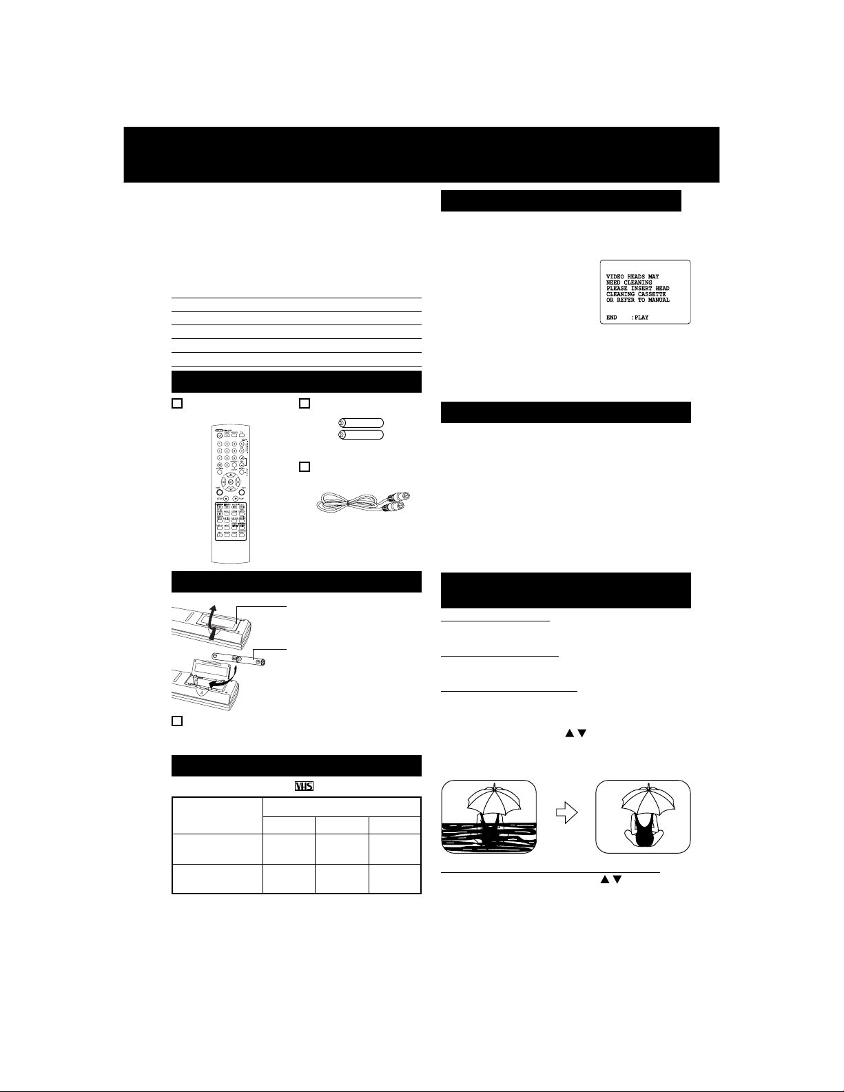
Head Cleaning
Playing older or damaged tapes may
eventually cause video heads to become
clogged.
Video Head Clog Sensor
During playback, this screen
appears if clogging is
detected.
To remove screen, press
PLAY on the remote or DECK.
• Use “dry” type head cleaning cassette only.
(Part No. NV-TCL30PT is recommended.)
• Follow cleaning tape instructions carefully.
Excessive use of tape can shorten head life.
Cleaning DECK
Use a soft cloth or dusting attachment of a
vacuum cleaner to remove dust from the
ventilation holes on the back sides and bottom of
the cabinet.
Plastic surfaces are easily scratched and can
be marred by alcohol and various solvents.
Avoid excessive use of oil-based furniture
polishes since the materials used in the cabinet
will accumulate more dust. We recommend
using a non-abrasive, antistatic cleaner and
polisher.
Features for a Quality Picture
(VCR)
Digital Auto Picture
Automatically controls the video output signal for
less noise depending on the tape condition.
Digital Auto Tracking
Continuously analyzes the signal and adjusts for
optimum picture quality.
Manual Tracking Control
(to reduce picture noise)
Use during Playback and Slow Motion mode to
reduce picture noise.
Press CH (TRACKING) / on the remote
control or on DECK until the picture clears up.
To return to Auto Tracking, press POWER off,
then on again a few seconds later.
R
R
R
R
V-Lock Control (to reduce picture jitter)
In Still mode, CH (TRACKING) / operate as a
V-Lock control.
R
R
R
R
4

Table of Contents
Initial Setup (Connection)
DVD / VCR
Important Safeguards and Precautions ................................. 2, 3
Before Using ................................................................................. 4
DECK & Cassette Information ................................................ 6 , 7
Location of Controls ............................................................ 8 ~ 10
On Screen Displays / Light-up Indicators ................................. 11
Connections ....................................................................... 12 ~ 15
Initial Setup for Basic Connections (Ready to Play) ............... 16, 17
Basic Operation
VCR
Reset Language, Channels, Clock, VCR’s Output Channel .......
18, 19
Playback/ Record on a Tape................................................ 20, 21
DVD
Basic DVD Operation ........................................................... 22, 23
VCR Operation
Timer Recording ................................................................... 24, 25
MTS Broadcast/ VHS Hi-Fi Stereo System ......................... 26, 27
Multi-Brand Control Feature ................................................ 28, 29
Tape Operation (Search System) ............................................ 30 ~ 32
Special VCR Features .......................................................... 33, 34
Copying Your Tapes (Dubbing) .....................................................35
Initial Setup
Basic Operation VCR Operation DVD Operation For Information
DVD Operation
Disc Operation .................................................................... 36 ~ 41
DVD-RAM Operation (DVD-RAM only) ...................................... 42, 43
DVD Operation using On-Screen Displays ...................... 44 ~ 48
MP3/JPEG Playback Operation ......................................... 49 ~ 51
Settings for DVD Operation ............................................... 52 ~ 55
Language Code List ................................................................... 56
For Your Information
Warning and Instruction Displays............................................. 57
Before Requesting Service.................................................. 58, 59
Index ...................................................................................... 60, 61
Memo ..................................................................................... 62, 63
5
DECK & Cassette Information
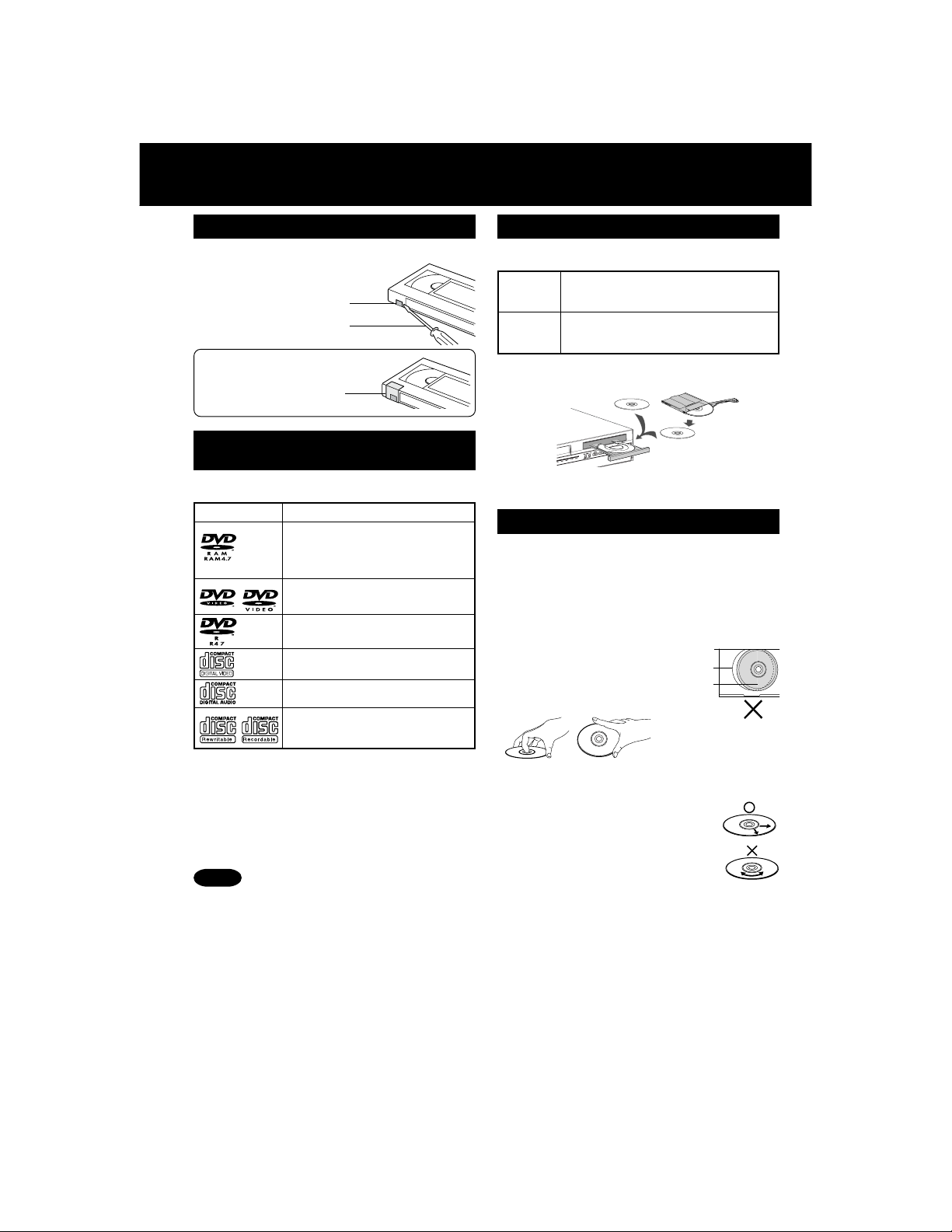
Prevent Accidental Tape Erasure
Break off the tab to prevent recording.
Record Tab
Screw driver
To record again
Cover the hole
with cellophane tape.
Disc formats supported by this
DECK
DECK can play back discs bearing any of the
following marks:
Logo Disc type
DVD-RAM (Version 1.1 of the
Video Recording Format a
unified video recording
standard)
DVD (DVD-Video)
DVD-R (DVD-Video formatted
discs [finalized])
Video CD
CD (CD-DA)
CD-R/CD-RW
• CD-DA format
• MP3/JPEG file and finalized.*
[Discs Played 8 cm (3
* A process that allows play on compatible
equipment.
Discs which cannot be played
• DVD with Region No. other than “1” or “ALL”
• PAL discs, DVD-ROM, DVD-Audio, DVD-RW,
DVD+R, DVD+RW, CD-ROM, CDV, CD-G, CVD,
SVCD, SACD, CD-TEXT, Divx Video Disc,
Photo-CD and MPEG4 Video Disc
″″
″) or 12 cm (5
″″
Notes
• The digital audio content side of DualDiscs do
not meet the technical specifications of the
Compact Disc Digital Audio (CD-DA) format so
may not play back in this unit.
• Do not use irregularly shaped discs (e.g.
heart-shaped), as these can damage the unit.
• It may not be possible to play CD-R, CD-RW,
DVD-R and DVD-RAM in all cases due to the
type of disc or condition of the recording.
6
″″
″)]
″″
DVD-RAM discs
DVD-RAM discs must meet the following
conditions for this unit to be able to play them.
• Non-cartridge discs
Type
Capacity
• Remove TYPE 2 and 4 discs from their cartridges
before use, then return them when you are
finished. Read the instructions for the disc
carefully.
• Some parts of the disc, for example where one
program ends and another begins, may not play
smoothly.
• Discs that can be removed from their
cartridges (TYPE 2 and 4)
• 12 cm (5″) 9.4 GB (double-sided)
and 4.7 GB (single-sided)
• 8 cm (3″) 2.8 GB (double-sided)
Disc Handling
Handling precautions
• Sticking a label on the disc may impair DVD-R
playback.
• Do not attach sticker to discs. (Do not use discs
with exposed adhesive from tape or left over
peeled-off stickers.)
• Only hold disc by edges as shown below.
Fingerprints, dirt and scratches can cause
skipping and distortion.
• Do not write on label side of disc.
• Never use record
cleaning sprays, benzine,
thinner, static electricity
prevention liquids, or any
other solvent.
• Do not try to close disc tray when disc is not
properly placed.
To clean disc surface
With a soft, damp (water only) cloth,
gently wipe from the center hole to the
outer edge as shown below. (Wiping in
a circular pattern will scratch the
surface.)
• DVD-RAM, DVD-R :
Clean only with the DVD-RAM disc
cleaner available. Never use cloths or cleaners
for CDs etc.
If disc is brought from a cold to a warm
environment, moisture may form on the disc
Wipe away moisture with a soft, dry, lint-free cloth
before using disc. (See above.)
Improper disc storage
Discs could be damaged if stored or left in areas:
• exposed to direct sunlight.
• that are humid or dusty.
• near heat (i.e. heater, radiator, etc.).
Disc tray
Disc

Specifications
Power Source: 120 V AC, 60 Hz
Power Consumption:
Video Signal: EIA Standard NTSC color
Video Recording System: 4 rotary heads helical scanning system
Audio Track: 1 track (Normal), 2 channel (Hi-Fi Audio Sound)
Tuner
Broadcast Channels: VHF 2 ~ 13, UHF 14 ~ 69
CABLE Channels: Midband A through I (14 ~ 22), Superband J through W (23 ~ 36)
Input/Output Terminal: Audio/Video Line Input/Output, RF Input/Output
Input Terminal: Audio/Video Line Input (Front)
Output Terminal: S-Video Output (DVD only), Component Video Output (DVD only)
Operating Temperature: 5 °C ~ 40 °C (41 °F ~ 104 °F)
Operating Humidity: 10 % ~ 75 %
Weight: 3.7 kg (8.2 lbs.)
Dimensions: 430 (W) × 93 (H) × 255 (D) mm
Discs Played
(1) DVD-Video Disc 12 cm (5″) single-sided single-layer
DVD-RAM Disc 12 cm (5″) 9.4 GB (double-sided) and 4.7 GB (single-sided)
(2) Compact Disc 12 cm (5″) disc
(CD-DA, Video CD) 8 cm (3″) disc
(CD-R/CD-RW, MP3, JPEG)
Digital Audio Output: Digital Optical Connector
Pickup: Wavelength : 655 nm (DVD), 790 nm (Video CD/CD)
Note:Designs and specifications are subject to change without notice.
Power On: Approx. 22 watts, Power Off: Approx. 0.9 watts
Hyperband AA ~ EEE (37 ~ 64), Lowband A-5 ~ A-1 (95 ~ 99)
Special CABLE channel 5A (01), Ultraband 65 ~ 94, 100 ~ 125
Audio Output 2 (L), (R)
16-15/16″ (W) × 3-11/16″ (H) × 10-1/16″ (D) inch
12 cm (5″) single-sided double-layer
12 cm (5″) double-sided double-layer (one layer per side)
8 cm (3″) single-sided single-layer
8 cm (3″) single-sided double-layer
8 cm (3″) double-sided double-layer (one layer per side)
8 cm (3″) 2.8 GB (double-sided)
Laser power : CLASS II
Definition of Terms (DVD)
Angle: Some DVD discs feature scenes simultaneously shot from different angles.
Chapter Number: Titles are subdivided into numbered sections. You can quickly search for
DVD: A high-density optical disc on which high-quality pictures and sound have been
Playback Control: With Video CD (version 2.0), scenes or information may be selected for viewing
Subtitles: Written dialogue which appears at the bottom of the screen.
Time Number: The elapsed play time from the start of a disc or title. Use to quickly find
Title Number: For DVD discs with two or more titles, the title is numbered as title 1, title 2, etc.
Track Number: Numbers assigned to tracks on Video CDs and CDs to allow specific tracks to
Video CD: CD containing picture and sound with same quality level as video tape.
U.S. Patent Nos. 4,631,603; 4,577,216; 4,819,098; 4,907,093; 5,315,448; and 6,516,132.
This product incorporates copyright protection technology that is protected by U.S. Patents and
other intellectual property rights. Use of this copyright protection technology must be authorized by
Macrovision, and is intended for home and other limited viewing uses only unless otherwise
authorized by Macrovision. Reverse engineering or disassembly is prohibited.
The ANGLE button can be used to view the scene from different angles.
a favorite scene using these numbers.
digitally recorded. DVD incorporates video compression technology (MPEG II)
and high-density recording technology which allow entire movies to be recorded
with incredible playback quality.
or listening from an interactive menu that appears on the TV screen.
scenes. (May not work with some discs.)
be quickly located.
This DECK also supports Video CDs with playback control (version 2.0).
Initial Setup
7
Location of Controls
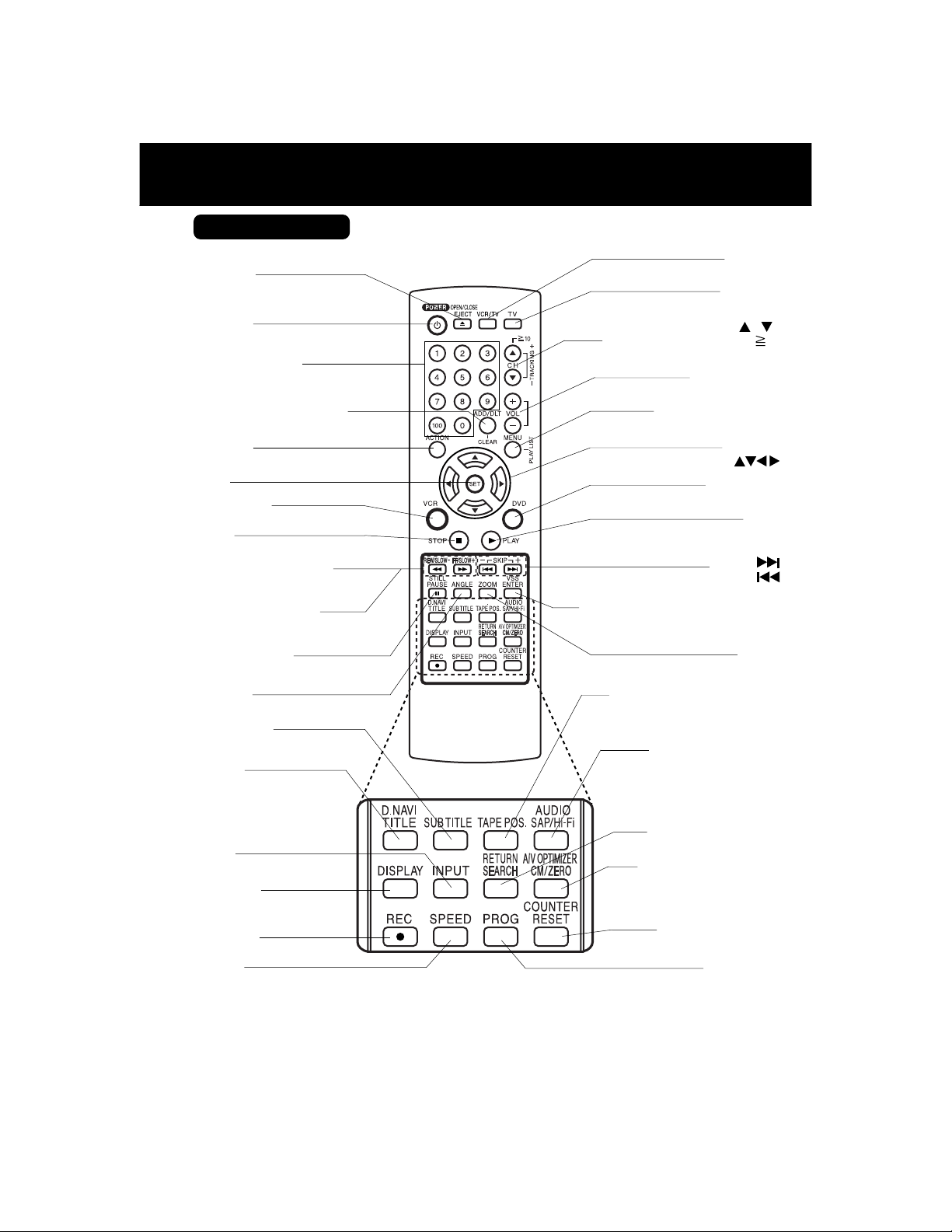
Remote Control
EJECT* /
OPEN / CLOSE
pp. 20,
22
POWER
NUMBER keys
ADD/DELETE /
pp. 19,
38, 40
ACTION
pp. 18
, 52
SET
VCR mode
p. 28
STOP
pp. 20,
22
REWIND /
SLOW-
pp. 20,
23
FAST FORWARD /
SEARCH/SLOW+
pp. 20,
23
PAUSE /
pp. 20,
23
ANGLE
p
. 37
SUB TITLE
p
. 36
TITLE
/
DIRECT NAVIGATOR
p
. 41, 42
CLEAR
SEARCH
STILL
Bold: VCR Function /
:
DVD Function
Italic
/
Bold Italic:VCR and DVD Functions
/ Normal: Others
CHANNEL / /
TRACKING / V-LOCK /
pp. 4, 21,
VOLUME + / -
MENU/ PLAY LIST
DVD mode
SKIP+
Virtual Surround Sound (V.S.S.)
TAPE POSITION /STATUS
AUDIO
(SAP / Hi-Fi)
VCR/TV
p. 21
TV mode
p. 28
p. 28
p
. 41, 43
SELECT
p.
PLAY
pp. 20,
SKIP-
p
ENTER
pp
. 23,
ZOOM
p
p. 32
pp. 27,
10
22
28
22
. 23
/
28
. 37
36
INPUT
p. 35
DISPLAY
p. 11,
44
RECORD
p. 21
SPEED
p. 21
*EJECT button: When this button is pressed in VCR mode, the tape is ejected.
This button is inoperative if pressed during recording.
If pressed in DVD mode, the disc tray opens or closes.
8
RETURN
/ SEARCH
pp
. 22,
30
COMMERCIAL SKIP /
ZERO SEARCH
A/V OPTIMIZER
pp. 30,
55
COUNTER RESET
p. 30
PROGRAM
p. 24
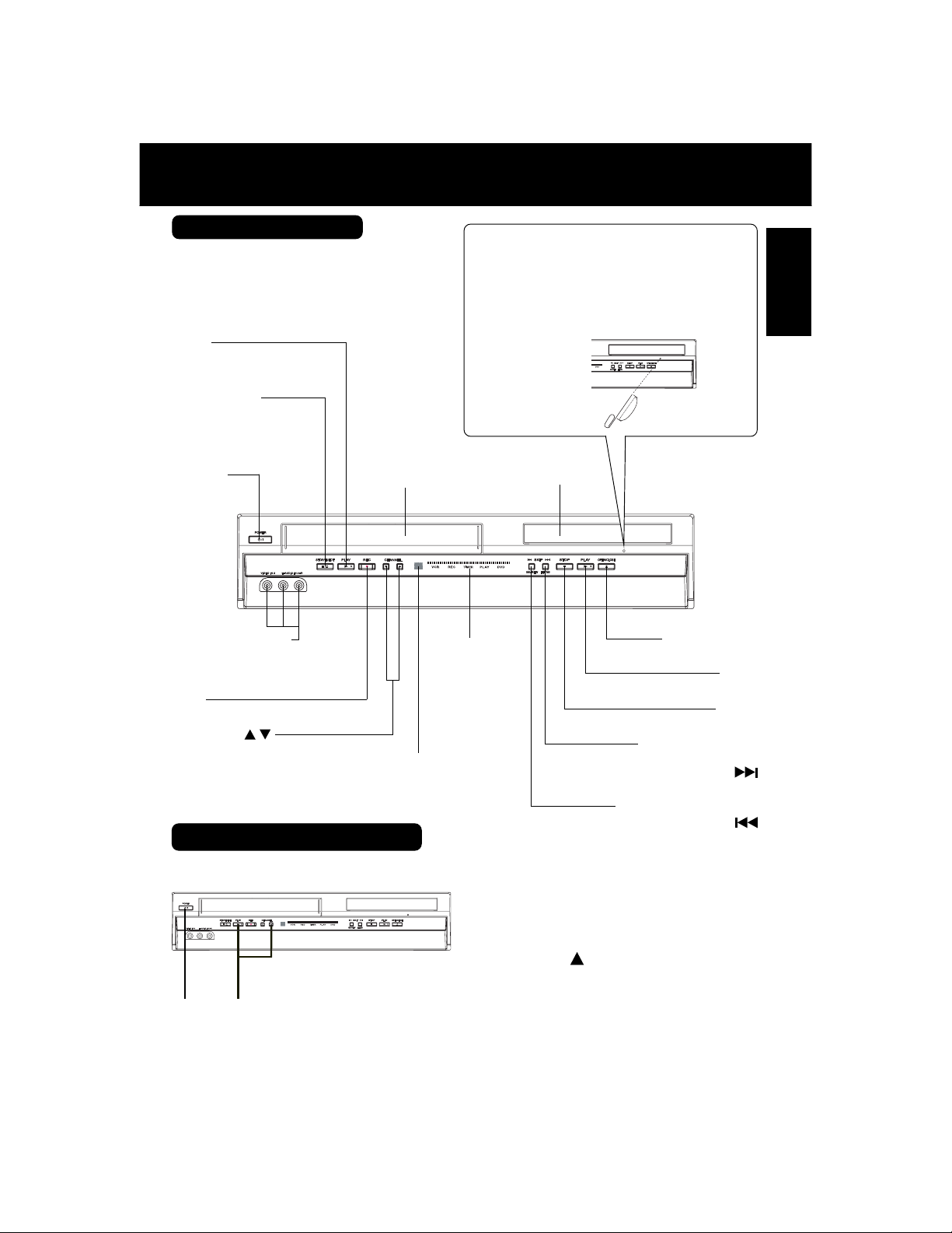
Front View of DECK
Bold: VCR Function
Italic
:
Bold Italic:VCR and DVD Functions
Normal: Others
PLAY
p. 20
DVD Function
If the disc cannot be removed...
First, unplug DECK. Then, prepare a rigid wire
(e.g. an extended paper clip) and, applying
moderate force, insert it straight into the hole at
the base of the tray.
The tray will eject a little. Now, pull the tray all
the way out and remove the disc.
Initial Setup
STOP/EJECT
p. 20
POWER
Audio/Video Input
Connector 2
(LINE 2)
p. 35
REC
p. 21
CHANNEL /
TRACKING/V-LOCK
pp. 4, 21
Cassette
Compartment
Light-up
Indicators
p. 11
Remote
Sensor
Over 2 inches
Disc Tray
FAST FORWARD
REWIND /
Reset All Memory Functions
Returns to factory setting. Use if relocating DECK, or if Initial Setup needs to be redone.
• Make sure a tape is not inserted in the DECK.
OPEN/CLOSE
PLAY
STOP
/
SEARCH
SKIP
p. 20,
SEARCH
SKIP
p. 20,
p.
22
p.
22
p.
22
23
23
/
/
Turn DECK Power on.
1
2
Press and hold both VCR PLAY and
CHANNEL on the DECK for more
than 5 seconds.
• The power shuts off.
21
Perform “Initial Setup (Ready to Play)”
3
on page 16.
9
Location of Controls (continued)
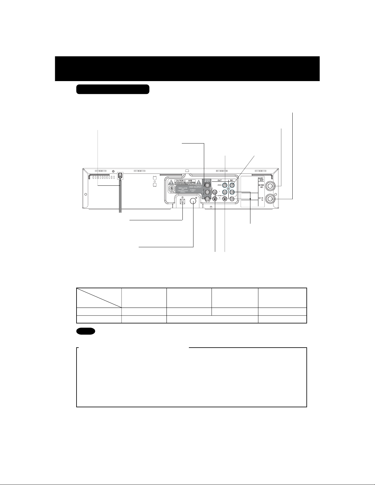
Rear View of DECK
AC Power Plug
• While plugged into an AC outlet,
this DECK consumes 0.9 W of
electrical power in off mode.
Component Video Output
Connector (Y, P
(DVD Only)
p.
13
Optical Digital Audio
Output Connector
(DVD Only)
p.
15
S-Video Out Connector
(DVD Only)
pp.
10, 13
Bold: VCR Function
:
Bold Italic
VCR and DVD Functions
VHF/UHF Antenna Input Terminal
p. 12
Video Output
B
, PR)
Connector
p.
Audio Output 2
Connector (L/R)
p.
13
Italic:DVD Function
VHF/UHF Antenna Output Terminal
p.12
Video Input
Connector
12
p. 35
Audio Input
Connector (L/R)
p. 35
Audio Output 1
Connector (L/R)
p.
12
The following table shows the status of the output jacks when in VCR or DVD mode.
Note
Video Output
Audio Out 1
Audio Out 2
VCR
DVD
• PROG functions on the remote are not available when using Component Video Output and
S-VIDEO OUT. Please set TV to either RF INPUT or VIDEO INPUT, and then press PROG.
YES
YES
Component
Video Output
N/A
S-VIDEO OUT
YES
Antenna Out
N/A
To enjoy PROGRESSIVE SCAN video
(1). Connect
(See p. 13.)
(2). When PROGRESSIVE OUT is set to “ON” in the DVD Main Menu (p. 55), a Progressive
Scan signal is output from the
Notes
• The screen may shift off-center when using progressive output. Please adjust the screen position if
this occurs. (Refer to your TV manual.)
• If the television is not progressive compatible, a progressive scan picture is not available.
Connect the Video Output or S-Video Output connector (see p. 12, 13) and set PROGRESSIVE
OUT to “OFF” in the DVD Main Menu. (See p. 55.)
Component Video Output
Component Video Output Connector
to the component video input terminals of a television.
.
10
VHF/UHF
YES
YES
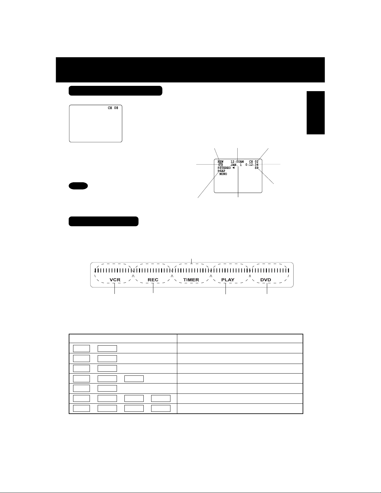
On Screen Displays / Light-up Indicators
On Screen Displays (VCR)
Function & Channel Displays
When a function button
is pressed, e.g. PLAY,
or you change
channels, and also if a
cassette is inserted, a
5-second display
appears.
VCR Status & Clock Displays
To display or remove
screen shown at right,
➛➛
➛ press DISPLAY.
➛➛
Note
• For on Screen Displays in DVD
mode, see p. 44.
Cassette inserted
(Rec Time Remaining
is displayed in OTR
mode, e.g. “0:25”.
See p.21.)
Broadcast Audio
Being Received
(See pp. 26, 27.)
Light-up Indicators
Light-up indicators allow easy confirmation
of current DECK function status.
Blank Tape/ No Signal Indications
Whenever a blank section of a tape comes up in
Play mode, or when the selected channel has no
broadcast signal with Weak Signal Display
Feature (p. 33) set to OFF, the TV screen will
turn solid blue.
Function Status
Current Time Channel
Counter
Tape Speed
(See p. 4.)
Date
(When clock is set, a 5-second
display appears.)
Timer Indicator
Lights up when DECK is set for Timer Recording, or
when One Touch Recording (OTR) is used. Flashes
when Timer Recording is set, but a tape has not been
inserted into DECK and when a power interruption
occurs during Timer Programming.
Initial Setup
VCR mode Indicator
Lights when output
selection is VCR mode.
Flashes in Auto Clock
Set or Channel Auto Set.
VCR REC Indicator
Lights up during
recording. Flashes in
Rec. Pause mode.
<Light-up combination example>
Light-up Indicator Function Status
+
VCR
VCR
VCR
VCR
DVD
VCR
PLAY
➛➛
➛
➛➛
➛➛
➛
➛➛
+
+
+
+
PLAY
REC
TIMER
TIMER
PLAY
REC
TIMER
➛➛
➛
➛➛
➛➛
➛
➛➛
+
REC
TIMER
REC
➛➛
➛
➛➛
➛➛
➛
➛➛
PLAY
VCR
PLAY Indicator
Lights during playback in
either VCR mode or DVD
mode. Flashes in Still,
Frame by Frame, or
Slow mode.
VCR playback in progress [See p. 20]
VCR recording in progress [See p. 21]
VCR timer setting in progress [See pp. 24, 25]
VCR Timer Recording in progress [See pp. 24, 25]
DVD playback in progress [See pp. 22, 23]
VCR fast forward in progress [See p. 20]
VCR rewind in progress [See p. 20]
DVD mode Indicator
Lights when output
selection is DVD mode.
11
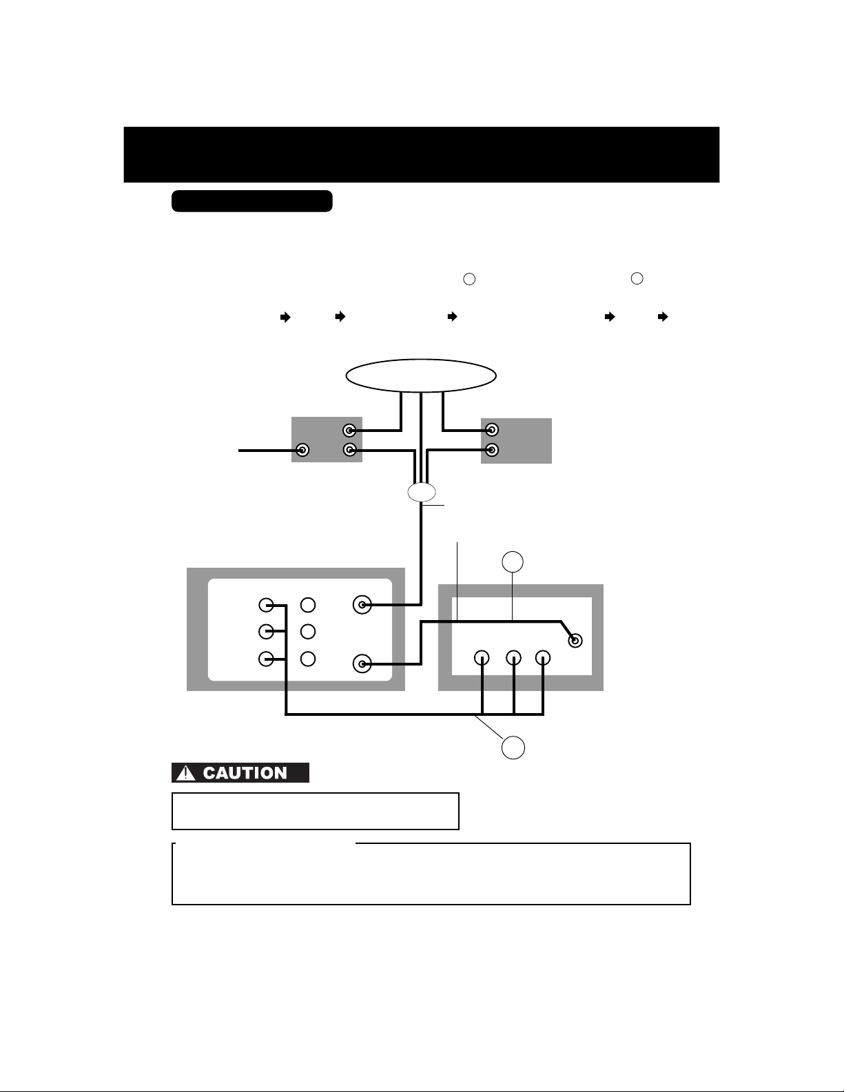
Connections
Basic Connections
• If your TV has AUDIO and VIDEO IN terminals, connect them to DECK for higher
quality picture and sound.
• You can enjoy stereo sound even if your TV is not stereo by connecting a stereo amplifier
to DECK.
• Connect DECK and TV with an RF Coaxial Cable
supplied) as shown in the figure below.
a
(supplied) or an AV Cable b (not
■■
■ DSS Receiver DECK TV
■■
DSS
Receiver
IN
IN
OUT
DVD/VCR DECK
IN FROM ANT.
IN 1OUT
VIDEO
AUDIO
L
R
VHF/UHF
OUT TO TV
■■
■ DECK TV
■■
Antenna or Cable
or
1 Disconnect antenna or cable from TV and
connect to DECK.
2 Connect DECK to TV with RF Coaxial Cable.
IN
OUT
TV
AUDIO IN
R
■■
■ Cable Box DECK TV
■■
Cable Box
RF COAXIAL CABLE
a
(supplied)
VHF/
UHF
VIDEO
IN
L
AV CABLE
b
When using “Nut type” RF coaxial cables, tighten with
fingers only. Overtightening may damage terminals.
Note to CABLE system installer
This reminder is provided to call the CABLE system installer’s attention to Article 820-40 of the NEC
in USA (and to the Canadian Electrical Code in Canada) that provides guidelines for proper
grounding and, in particular, specifies that the cable ground shall be connected to the grounding
system of the building, as close to the point of cable entry as practical.
(not supplied)
12
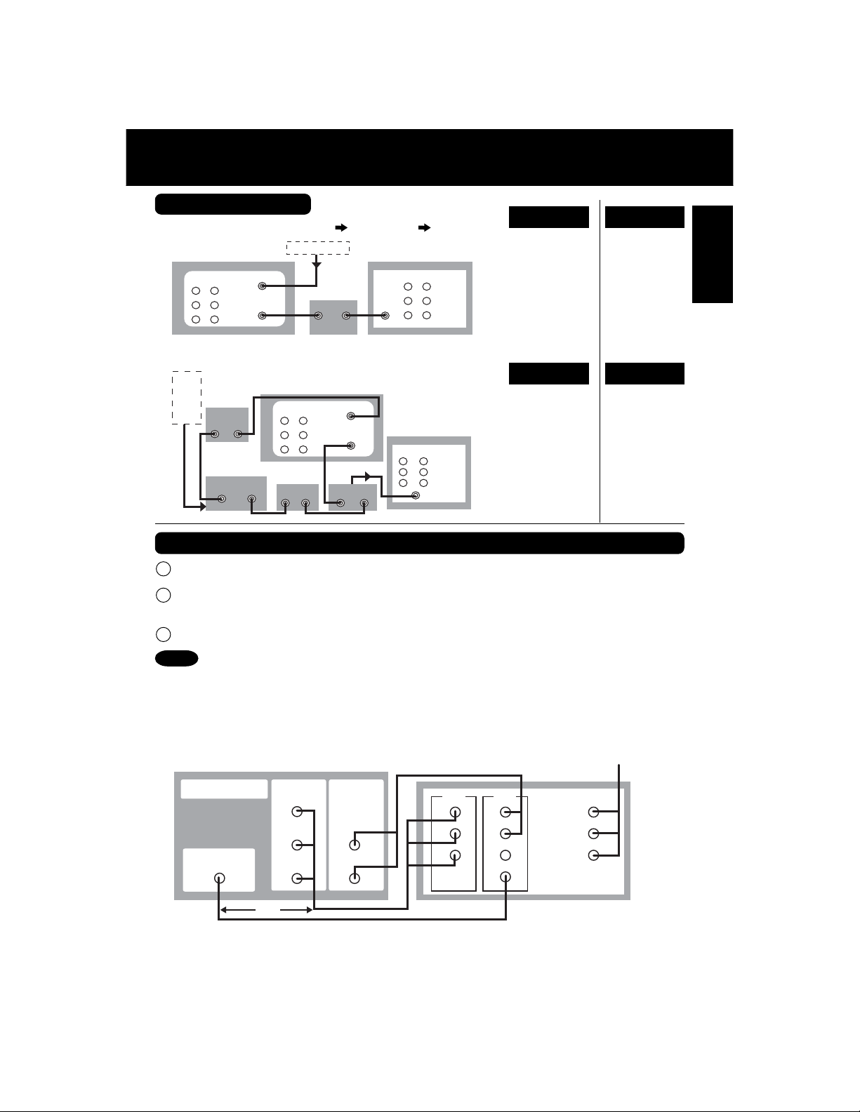
Other Connections
■■
■ With a Cable Box (DECK Cable Box TV)
■■
DVD/VCR DECK
OUT IN1
■■
■ Connect With Two Cable Boxes
■■
ANT
or
CATV
IN FROM ANT.
VHF/UHF
OUT TO TV
Cable Box
IN OUT
2-Way Splitter
OUT1 OUT2
ANT or CATV
Cable Box
IN OUT
DVD/VCR DECK
OUT IN1
Cable Box
IN FROM ANT.
VHF/UHF
OUT TO TV
A/B Switch
IN OUT IN 1 IN 2
VHF/
UHF
IN
IN
R
L
OUT
R
L
OUT
AUDIO
VIDEO
VHF/UHF
AUDIO
VIDEO
TV
TV
• view any
(including
scrambled)
channel.
• use Remote
Control to select
channels without
using Multi-brand
control feature.
• record and view
both scrambled
and unscrambled
channels if
additional
equipment is
added.
This connection
requires: two
converter boxes,
an A/B switch,
and a 2-way
splitter.
You CannotYou Can
• record
scrambled
channels.
You CannotYou Can
• view a channel
other than the
one selected
for any type of
recording.
• set a Timer
recording of a
channel unless
you select it on
the Cable Box.
Connections For DVD Only (enjoying higher picture quality)
Connect AUDIO OUT2 (L, R) to the AUDIO IN (L, R) of the TV. (audio input for
1
COMPONENT or S-VIDEO mode).
If your TV has COMPONENT VIDEO INPUT, connect to COMPONENT VIDEO OUT.
2
If your TV does not have COMPONENT VIDEO INPUT but has S-VIDEO INPUT, connect
to S-VIDEO OUT.
When in DVD mode, set your TV to either COMPONENT VIDEO IN or S-VIDEO IN.
3
Notes
• You can watch DVDs through the S-VIDEO or COMPONENT VIDEO, VHF/UHF OUT TO TV,
and VIDEO OUT connections to your TV. The VCR and TUNER pictures are available only
from the VIDEO OUT and VHF/UHF OUT TO TV connections to your TV.
• PROG functions on the remote are not available when using S-VIDEO OUT and COMPONENT
Video Output. Please set TV to either RF INPUT or VIDEO INPUT, and then press PROG.
• TV must have capability to accept and display a progressive scan signal to use
PROGRESSIVE mode. Consult your TV operating instructions.
From DECK’s
DVD/VCR DECK
DVD OUTPUT
S-VIDEO OUT
COMPONENT
VIDEO OUT
Y
B
P
P
R
AUDIO OUT2
L
R
TV
IN
YL
B
P
R
IN
RP
AUDIO
VIDEO
S-VIDEO
IN
A/V OUTPUT
IN
Initial Setup
or
13
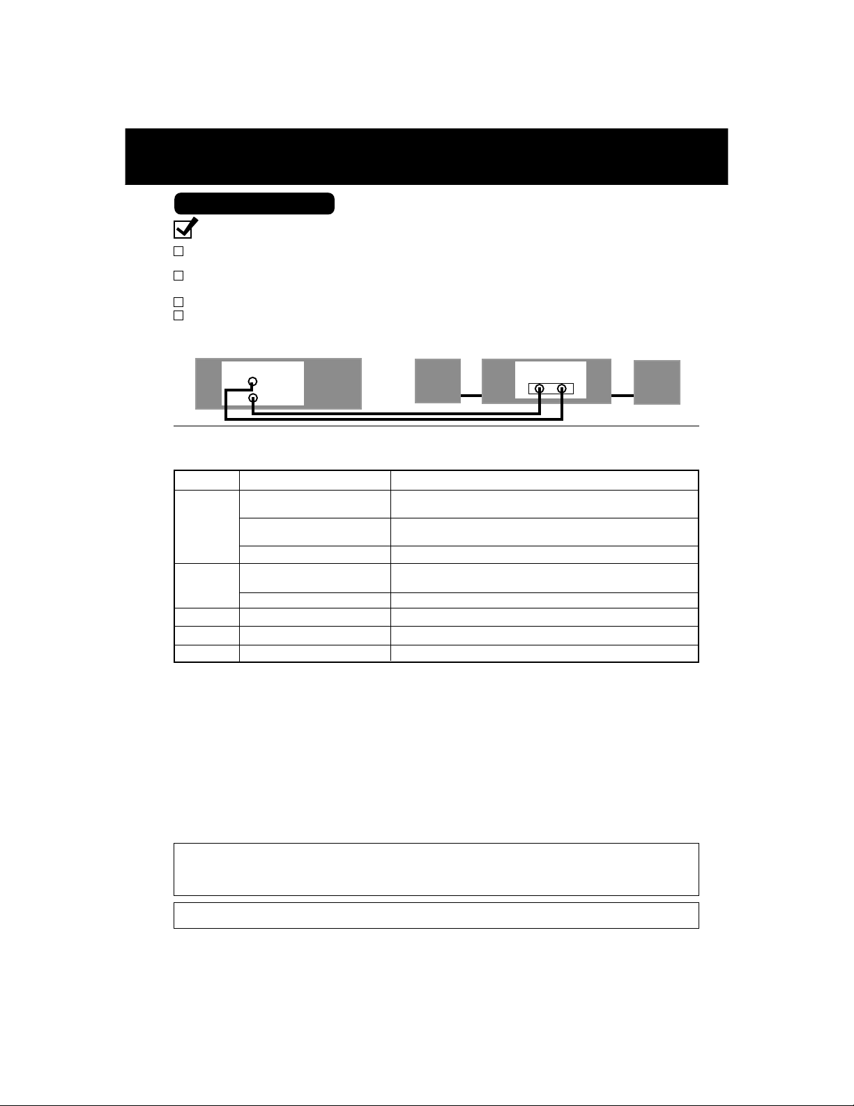
Connections (continued)
Audio Connections
Ready Checklist
Turn down the volume, then turn DECK, as well as other equipment to be connected, off before
proceeding with connection.
Do not block ventilation holes of any of the equipment and arrange them so that air can circulate
freely.
Read through the instructions before connecting other equipment.
Ensure that you observe the color coding when connecting audio and video cables.
■■
■ Connecting Amplifier (2ch stereo system) [Analog connection]
■■
DVD/VCR DECK
AUDIO OUT2
L
R
Enjoying digital audio output from the digital audio output connector
Notes on audio output from the optical digital audio output connector
Disc Sound recording format Optical digital audio output from connector
Dolby Digital
DVD-Video
DVD-RAM
Video CD
CD
MP3
*1 The type of audio output from the connector can be selected by the Settings for DVD Operation.
(See p. 53.)
*2 When “LPCM(DVD)” is set to OFF in the DVD Main Menu, only 48 kHz sampling/16 bit is ouput.
When set to ON, sampling of sound quality greater than 48 kHz/16 bit is reduced to 48 kHz/16 bit.
(See page 53.)
For your reference:
• Dolby Digital is a digital sound compression technique developed by the Dolby Laboratories Licensing
Corporation. Supporting 5.1-channel surround sound, as well as stereo (2-channel) sound, this
technique enables a large quantity of sound data to be efficiently recorded on a disc.
• Linear PCM is a signal recording format used in CDs. While CDs are recorded in 44.1 kHz/16 bit, DVDs
are recorded in 48 kHz/16 bit up to 96 kHz/24 bit.
• If you have a Dolby Pro Logic Surround decoder, you will obtain the full benefit of Pro Logic from the
same DVD movies that provide full 5.1 channel Dolby Digital soundtracks, as well as from titles with the
Dolby Surround mark. For information on Panasonic or Technics Dolby Pro Logic Surround Sound
Decoders please contact your local dealer.
Linear PCM
(48/96 kHz 16/20/24 bit)
DTS Bitstream or PCM (48 kHz sampling/16 bit only)*
Dolby Digital
Linear PCM(48 kHz/16 bit) Linear PCM (2 ch)
MPEG1 PCM (44.1 kHz sampling)
Linear PCM Linear PCM (44.1 kHz sampling)
MP3 PCM (It depends on the MP3 file)
Speaker
Dolby Digital bitstream (1 - 5.1 ch)
or PCM (48 kHz sampling/16 bit only)*
Linear PCM (2 ch)
(48 kHz sampling/16 bit only)*
Dolby Digital bitstream (1 - 5.1 ch)
or PCM (48 kHz sampling/16 bit only)
Amplifier Speaker
AUDIO IN
R L
2
1
1
Manufactured under license from Digital Theater Systems, Inc. US Pat. No’s. 5,451,942, 5,956,674,
5,974,380, 5,978,762, 6,487,535 and other US. and world-wide patents issued and pending. “DTS”
and “DTS 2.0 + Digital Out” are trademarks of Digital Theater Systems, Inc.
Copyright 1996, 2003 Digital Theater Systems, Inc. All Rights Reserved.
Manufactured under license from Dolby Laboratories.
Dolby and the double-D symbol are trademarks of Dolby Laboratories.
14
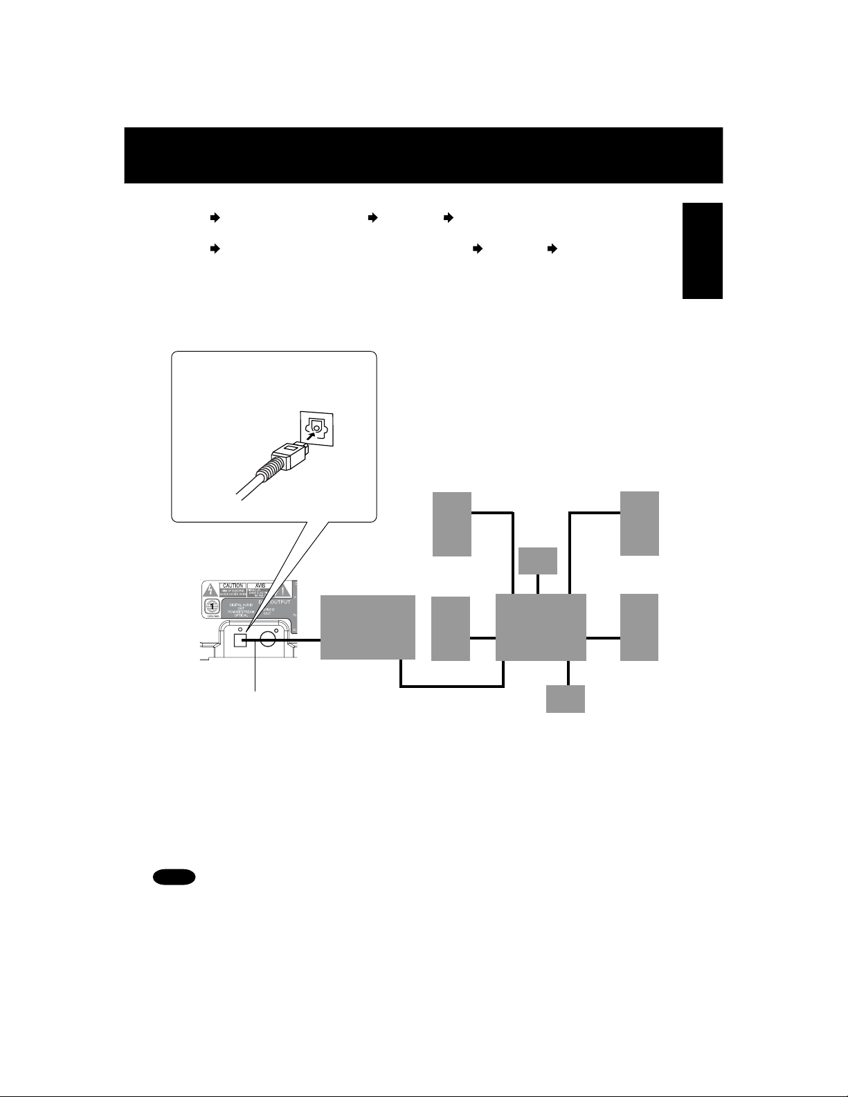
■■
■ Connecting Amplifier (5.1 ch Surround system) [Digital connection]
■■
DECK Dolby Digital Decoder Amplifier Speaker
or
DECK DTS (Digital Theater Systems) Decoder Amplifier Speaker
When DVDs recorded in Dolby Digital or DTS are played, Dolby Digital bitstream or DTS
bitstream is output from the DECK OPTICAL digital audio output connector. When DECK
is connected to a Dolby Digital decoder or DTS decoder, you can enjoy theater-quality
audio in your home. [An optical digital audio cable (optional) is required when an optional
Dolby Digital decoder or DTS decoder is used.]
Notes on connecting an optical
digital audio cable (optional)
• Remove the attached cap, and firmly
connect the cable to the connector.
Initial Setup
Initial Setup
Surround
Speaker
[5.1ch Surround system]
Surround
Speaker
Center
Speaker
DVD/VCR DECK
(Rear)
Optical Digital
Decoder with Dolby
Digital /DTS
processing (optional)
To Optical
Digital Audio
Input Connector
Front
Speaker
Front
Speaker
Amplifier
Subwoofer
Audio Cable
(optional)
Caution for optical digital audio output connector:
• When connecting an amplifier (with an Optical Digital Input Connector) which does not contain the
Dolby Digital or DTS decoder, be sure to select “PCM” at “Dolby Digital” and “PCM” at “dts” in
Settings for DVD Operation “Audio Output” (see p. 53).
Otherwise, any attempt to play DVDs may cause such a high level of noise that it may be harmful
to your ears and damage your speakers.
• When a Dolby Digital/DTS decoder is connected, please select “Bitstream” at “dts” or “Dolby
Digital” in Settings for DVD Operation “Audio Output”.
If “PCM” is selected, there will be stereo sound. (See p. 53.)
• Video CDs and CDs can be played as usual.
Note
• Some DTS decoders which do not support DVD-DTS interface may not work properly with DECK.
15
Initial Setup for Basic Connections (Ready to Play)
Before doing Initial Setup
Turn TV on.
1
See connections RF Coaxial Cable Connection and AV Cable Connection on
2
page 12.
<RF Coaxial Cable Connection>
ÖSet TV to channel 3.
<AV Cable Connection>
ÖSet TV to VIDEO.
[DECK
• Go to “Initial Setup (Ready to Play).” (See below.)
3
[Cable Box
• Turn on Cable Box and set it to your Public Broadcasting Station (PBS) channel in your time zone.
• If you use a DSS Receiver, it must be turned off.
➛➛
➛ TV]
➛➛
➛➛
➛ DECK
➛➛
➛➛
➛ TV], [DSS
➛➛
➛➛
➛ DECK
➛➛
➛➛
➛ TV]
➛➛
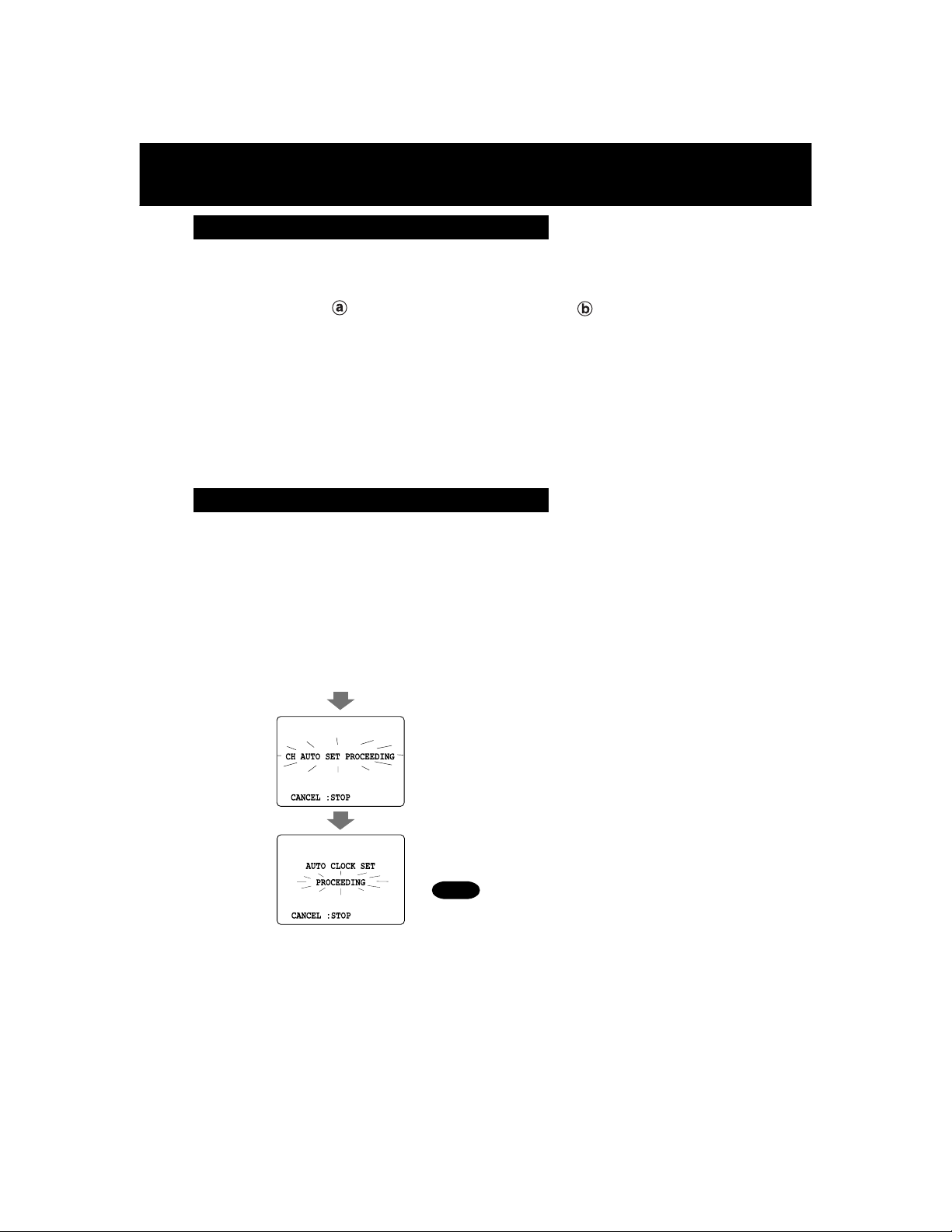
Initial Setup (Ready to Play)
Press VCR on remote for VCR mode.
1
Plug DECK Power Cord into AC wall outlet. DECK comes on and auto channel and
2
clock set starts.
• If screen below does not appear, check DECK - TV connection and, if TV is tuned to channel 3, try
switching it to channel 4.
• To change VCR’s output channel, please see “VCR’s Output Channel” on page 19.
Plug VCR Power plug into an AC wall outlet.
16
Notes
• Function buttons are void during Initial Setup.
• To eject a tape during Auto Set, press EJECT on remote or
STOP/EJECT twice on DECK.
Then make settings manually. (See p. 18.)
• If Auto Clock Set takes more than 30 minutes, press STOP
and perform settings manually. (See p. 18.)
Continued on next page...
*Important: If a remote control button does not work when pressed,
press the VCR button on the remote and try the button again.
EJECT
ACTION
SELECT
SET
VCR
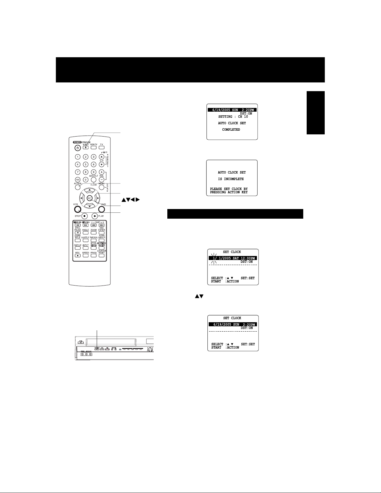
Settings are made automatically.
When complete, this screen appears.
3
If “AUTO CLOCK SET IS INCOMPLETE”
appears, manually set clock (below).
Manual Clock Set
If Auto Clock Set was incomplete.
Press ACTION* on remote to display
1
CLOCK screen.
Initial Setup
STOP/EJECT
Press to select the month and SET to set.
2
In the same manner, select and set the date,
year, time, and DST (Daylight Saving Time).
Press ACTION to start clock and exit.
3
17
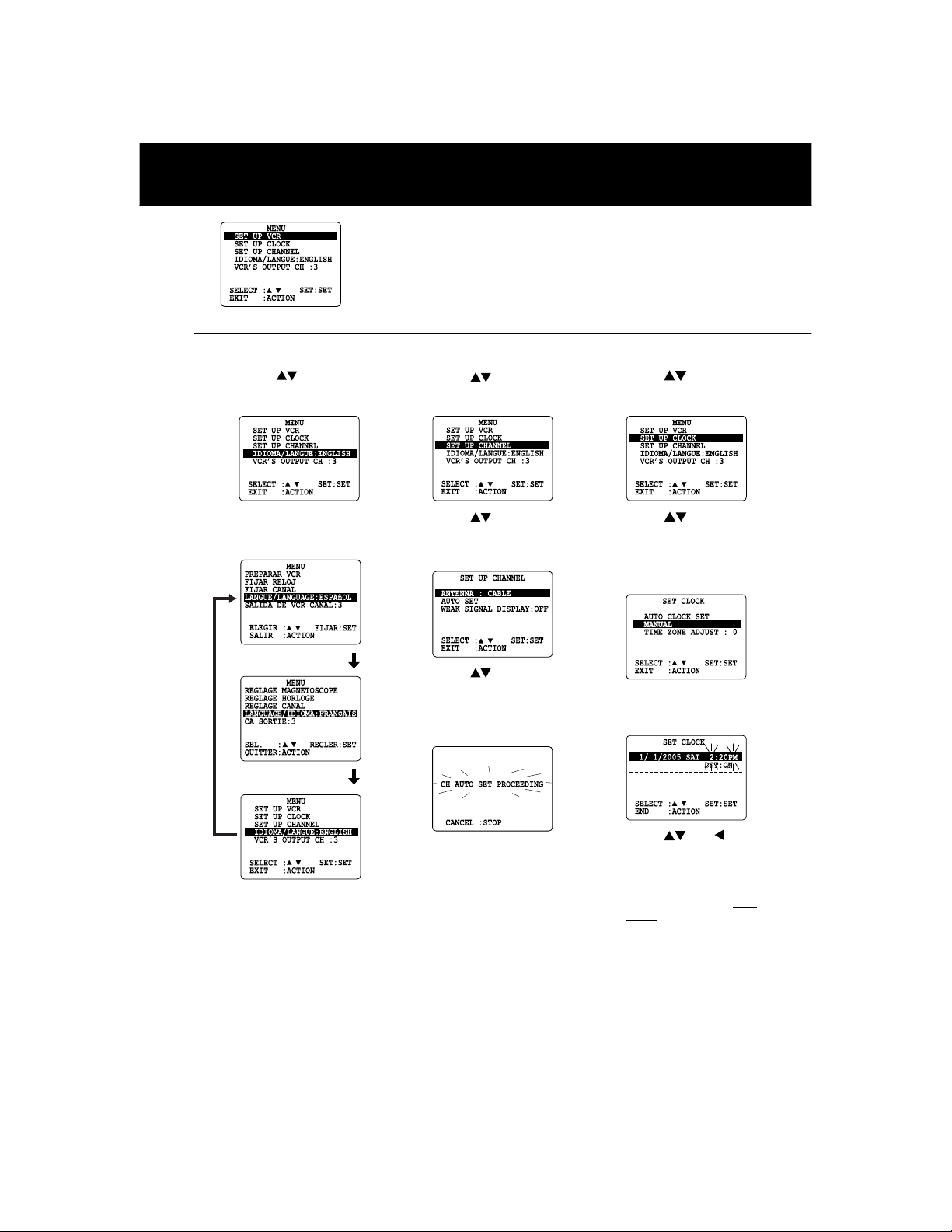
Reset Language, Channels, Clock,
1
■■
■ Language
■■
2
1) Press to select
language item.
2) Press SET repeatedly to
change language item as
shown below.
For Spanish
Press ACTION*
to display MENU.
■■
■ Channels
■■
1) Press to select “SET
UP CHANNEL,” and press
SET.
2) Press to select
“ANTENNA,” then press
SET to set your antenna
system (“TV” or “CABLE.”)
3) Press to select
“AUTO SET,” then press
SET.
• If you use a Cable Box, set it
to the PBS channel in your
time zone.
• PROGRAM functions are not available when
using COMPONENT Video Output and S-VIDEO
OUT. Please set TV to either RF INPUT or VIDEO
INPUT, and then press PROGRAM.
■■
■ Clock
■■
1) Press to select “SET
CLOCK,” and press SET.
2) Press to select
“MANUAL,” and press
SET.
(For Auto Clock Set,
select “AUTO CLOCK
SET.”)
(“TIME ZONE ADJUST”
appears only when auto
clock is set.)
18
For French
For English
3) Press ACTION to exit.
• After Channel Auto Set is
finished, Auto Clock Set will
be performed.
3) Press and to select,
then set the date, time,
and DST (Daylight Saving
Time).
4) Press ACTION to start
Clock and exit this mode.
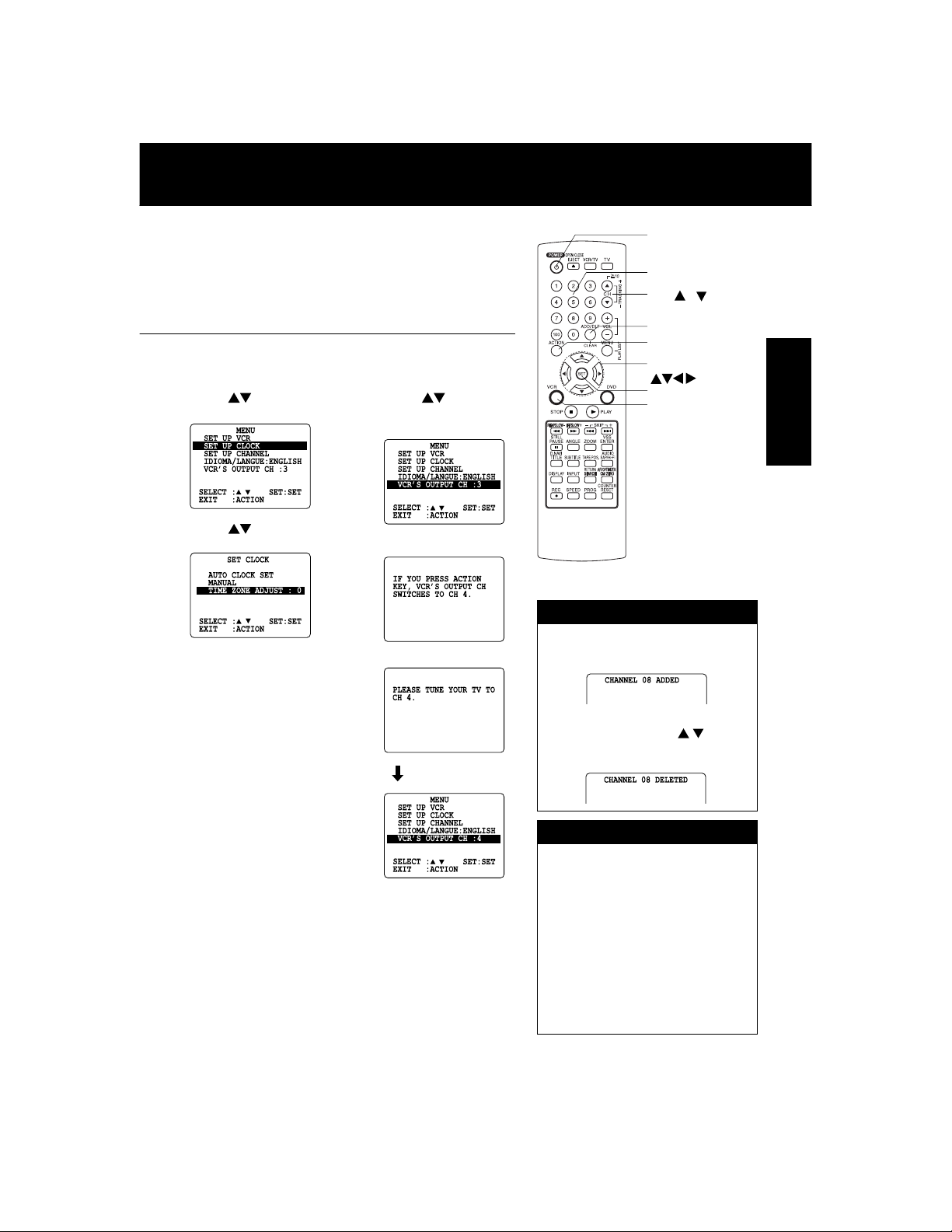
VCR’s Output Channel
*Important: If a remote control button does not work
■■
■ Time Zone Adjust
■■
(Only when Auto Clock is set.)
1) Press to select “SET
CLOCK,” and press SET.
2) Press to select “TIME
ZONE ADJUST,”
and press SET to subtract
or add hour(s) as
necessary.
3) Press ACTION.
• “TIME ZONE ADJUST”
returns to “0” if clock is set
manually.
when pressed, press the VCR button on the
remote and try the button again.
■■
■ VCR’s Output
■■
Channel
1) Press to select
“VCR’S OUTPUT
CH.,” and press SET.
2) Press SET.
3) Press ACTION.
After 3 seconds
POWER
NUMBER
keys
CH /
ADD/DLT
ACTION
SELECT
SET
VCR
Add or Delete a Channel
To add channel:
Select channel with NUMBER keys
and press ADD/DLT.
To delete channel:
Select channel with CH / or
NUMBER keys and press
ADD/DLT.
Basic Operation
• To Make Corrections,
repeat steps 1) ~ 3).
DST (Daylight Saving Time)
DECK auto adjusts clock for DST.
(p. 17.)
Spring (First Sunday in April)
DST:ON
Autumn (Last Sunday in October)
DST:ON
• If your area does not observe
• Keep these time changes in mind
➛➛
➛ Sets clock ahead one hour.
➛➛
➛➛
➛ Turns clock back one hour.
➛➛
Daylight Saving Time, select
DST:OFF.
when programming DECK for timer
recordings.
19
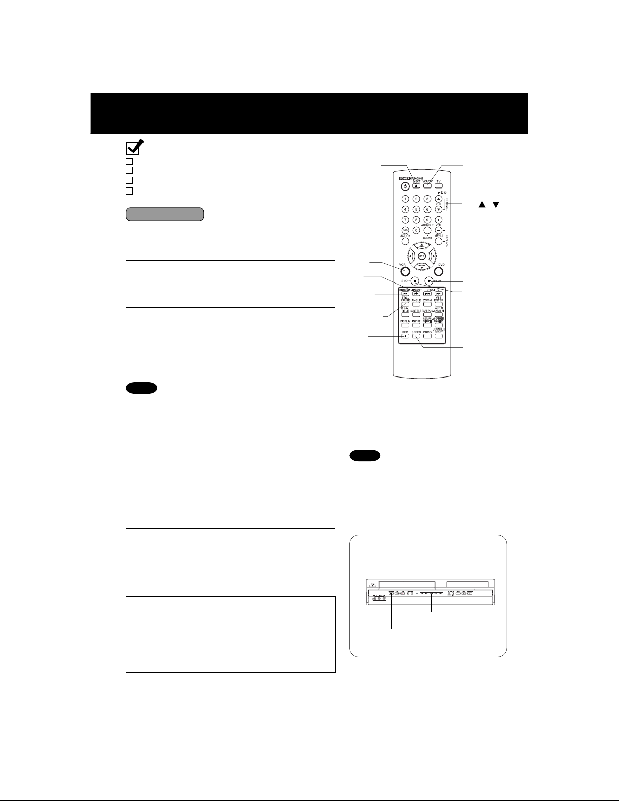
Playback/ Record on a Tape
Ready Checklist
All connections are made. (pp. 12 ~ 15)
TV and DECK are plugged in.
TV is on and tuned to CH 3, 4, or VIDEO.
Remote is in VCR mode. (Press VCR.)
➛➛
(
➛ The VCR mode Light-up Indicator lights on DECK.)
➛➛
Playback a Tape
Insert a tape.
1
• DECK power comes on. If Auto VCR/TV (see p. 34)
is set to “OFF,” press VCR/TV on the remote for
VCR mode.
Press PLAY* to play a tape.
2
• If tape has no rec. tab (p. 6), auto play begins.
• The PLAY Light-up Indicator lights on DECK.
Special Features During Play
■■
■ Forward/Reverse Scene Search
■■
➛➛
➛ Press FF/SLOW+ or REW/SLOW-.
➛➛
➛➛
➛ Press PLAY to release.
➛➛
After search has begun, each additional press of
FF/SLOW+ or REW/SLOW- changes speed as
shown below.
[SP] : Approx. 5× ↔ Approx. 7×
[SLP] : Approx. 11× ↔ Approx. 21×
Notes
• Picture interruption may occur with some TVs.
• FF and REW search speed may vary depending on
current tape position.
• After 10 minutes in search mode, VCR returns to Play
mode to protect the tape and the video heads.
■■
■ Still (Freeze) Picture
■■
➛➛
➛ Press PAUSE/STILL.
➛➛
➛➛
➛ Press PLAY to release.
➛➛
■■
■ Frame by Frame Picture
■■
➛➛
➛ Press PAUSE/STILL in Still mode.
➛➛
➛➛
➛ Press PLAY to release.
➛➛
■■
■ Slow Motion Picture
■■
➛➛
➛ Press FF/SLOW+ (increase speed) or REW/
➛➛
SLOW- (decrease speed) in Still mode.
➛➛
➛ Press PLAY to release.
➛➛
EJECT
VCR
FF/
SLOW+
REW/
SLOWPAUSE/
STILL
REC
Notes
• These features work best in SP or SLP
mode.
• The sound will be muted.
• To reduce picture noise, see “Manual
Tracking Control” on page 4.
• After 3 minutes in Still or Slow mode, VCR
stops to protect the tape and the video
heads.
VCR/TV
/
CH
DVD
PLAY
STOP
SPEED
Press STOP to stop a tape.
3
■■
■ Press REW/SLOW- or FF/SLOW+ in Stop
■■
mode to rewind or fast forward a tape.
■■
■ Press EJECT on remote, or STOP/EJECT on
■■
DECK to eject a tape.
S-VHS Quasi Playback (SQPB)
• Tapes recorded in S-VHS can easily be played back
using the same procedure as with VHS tapes.
• This VCR automatically distinguishes between S-VHS
and VHS tapes and plays them back.
• Picture quality will be normal VHS, not S-VHS and
picture noise may occur. (Color loss or picture
disruption during Search, Pause, etc. is normal.)
• S-VHS recording is not possible.
20
Playback using DECK buttons
2 Press PLAY.
■ Press STOP/EJECT to stop
and/ or eject a tape.
1 Insert a tape.
Light-up Indicators
 Loading...