

Page 1
Operating Instructions
Vol.2
Vol.2
Memory Card Camera-Recorder
Model No. AG-DVX200PJ
AG-DVX200PB
AG-DVX200PX
AG-DVX200EJ
AG-DVX200EN
AG-DVX200ED
This document explains in detail how to operate this device. Concerning basic operation, please
refer to the enclosed “Operating Instructions Vol.1” (printed document).
Please read these instructions carefully before using this product, and save this manual for future
use.
F0815MT0
ENGLISH
SQT1051
Page 2

Read this first
∫ About the recording method
for recording motion pictures
This unit can record motion pictures using three
different recording methods, including MOV,
MP4 and AVCHD
* AVCHD Progressive (1080/60p, 1080/50p)
supported.
MOV and MP4:
These recording methods are suitable for
editing images. Audio is recorded in linear
PCM.
≥ Those methods are not compatible with
motion pictures recorded in AVCHD format.
≥ Those methods can record motion pictures in
formats that support 4K. 4K motion pictures
offer a resolution four times higher than that
of full high-definition motion pictures.
AVCHD:
This recording method is suitable for playback
on a high-definition compatible external monitor.
Audio is recorded in Dolby
*
. (l 33, 141)
®
Digital.
∫ Regarding system frequencies
The NTSC/PAL region setting can be switched
in [SYSTEM FREQ]. (l 141, 178)
≥ You cannot store AVCHD scenes recorded
with different system frequencies on the
same SD card. If you have switched the
system frequency, use another SD card.
∫ Indemnity about recorded
content
Panasonic does not accept any responsibility
for damages directly or indirectly due to any
type of problems that result in loss of recording
or edited content, and does not guarantee any
content if recording or editing does not work
properly. Likewise, the above also applies in a
case where any type of repair is made to the
unit.
∫ About Condensation
(When the lens, the viewfinder
or LCD Monitor is fogged up)
Condensation occurs when there is a change in
temperature or humidity, such as when the unit
is taken from outside or a cold room to a warm
room. Please be careful, as it may cause the
lens, the viewfinder or LCD monitor to become
soiled, moldy, or damaged.
When taking the unit to a place which has a
different temperature, if the unit is accustomed
to the room temperature of the destination for
about one hour, condensation can be
prevented. (When the difference in temperature
is severe, place the unit in a plastic bag or the
like, remove air from the bag, and seal the bag.)
When condensation has occurred, remove the
battery and/or the AC adaptor and leave the
unit like that for about one hour. When the unit
becomes accustomed to the surrounding
temperature, fogginess will disappear naturally.
- 2 -
Page 3

∫ About security
Be careful about the possibility of theft or loss of
the unit, and be careful not to leave the unit
unattended. Please note that Panasonic does
not accept any responsibility for the
compromise, manipulation, and loss of
information caused by these events.
∫ Caution regarding laser beams
The lens may suffer damage if struck by a laser
beam. Make sure that laser beams do not strike
the lens when shooting in an environment
where laser devices are used.
∫ Cards that you can use with
this unit
SDHC Memory Card and SDXC Memory
Card
≥ 4 GB or more Memory Cards that do not have
the SDHC logo or 48 GB or more Memory
Cards that do not have the SDXC logo are
not based on SD Memory Card
Specifications.
≥ Refer to page 21 for more details on SD
cards.
∫ For the purposes of these
operating instructions
≥ The battery pack is referred to as the
“Battery”.
≥ SDHC Memory Card and SDXC Memory
Card are referred to as the “SD card”.
≥ Function that can be used for Recording
Mode:
Function that can be used for Playback
Mode:
≥ Scene(s) recorded with [REC MODE] set to
[MOV] or [MP4]: "MOV/MP4 scene(s)".
≥ Scene(s) recorded with [REC MODE] set to
[AVCHD]: "AVCHD scene(s)".
≥ Pages for reference are indicated by an
arrow, for example: l 00
≥ These operating instructions are designed for
use with models AG-DVX200PJ/PB/PX/EJ/
EN/ED. Such as screen illustrations are as an
example AG-DVX200PJ.
- 3 -
Page 4

Contents
Read this first .................................................2
Preparation
What you can do with this unit ..................... 6
Recording to the SD card ........................ 6
Linking to external devices ...................... 6
Names and Functions of Main Parts ............8
Power supply................................................ 15
Charging the battery .............................. 16
Inserting/removing the battery ............... 17
Charging and recording time ................. 18
Connecting to the AC outlet................... 20
Preparation of SD cards .............................. 21
Cards that you can use with this
unit......................................................... 21
Inserting/removing an SD card .............. 22
Turning the unit on/off................................. 23
Selecting a mode ......................................... 23
Using the LCD monitor/Viewfinder............. 24
Setting how to turn on/off the LCD
monitor and Viewfinder .......................... 24
Using the LCD monitor .......................... 24
How to use the touch screen ................. 25
LCD monitor adjustment........................ 26
Viewfinder adjustment ........................... 27
Recording yourself................................. 28
Setting date and time................................... 29
Using the menu screen ............................... 30
Manual Focus Assist .............................. 51
Focus Transition .................................... 52
White Balance...............................................55
Iris/Gain adjustment .....................................59
Iris adjustment........................................ 59
Gain adjustment ..................................... 61
Manual shutter speed ..................................63
Audio Input ...................................................66
Switching Audio Input ............................ 66
Adjusting the audio input level ............... 68
Counter display ............................................70
Setting the Time Code ........................... 70
Setting the User Information .................. 72
Setting the Recording Counter............... 73
Synchronizing the time code with an
external device ....................................... 73
USER button ................................................. 74
Setting the USER button ........................ 74
Using the USER button .......................... 75
Functions of the USER button ............... 76
Useful functions ........................................... 95
Color Bar Screen ................................... 95
ND filter .................................................. 96
Switching the screen indications/mode
information display ................................. 96
Using Operation Icons .................................97
Using of jog dial ...........................................98
Playback
Recording
Before recording .......................................... 31
Selecting the Recording Method ................ 31
Formatting media ................................... 32
Selecting a media to record ........................ 32
Recording motion picture with this
unit ................................................................ 33
Recording still pictures ............................... 34
Switching between Auto and Manual
Mode.............................................................. 36
Adjusting the Picture Quality...................... 38
Using the zoom ............................................ 40
Image Stabilizer Function ........................... 42
Focus ............................................................ 44
One Push AF ......................................... 47
Push AF ................................................. 48
Focus Assist .......................................... 48
Motion picture/Still picture playback ....... 101
Motion picture playback using
operation icon ...................................... 105
Useful functions ......................................... 106
Creating still picture from motion
picture .................................................. 106
Repeat Playback .................................. 107
Resuming the previous playback ......... 107
Playing back scenes or still pictures by
date ...................................................... 108
Editing
Deleting scenes/still pictures....................109
Protecting scenes/still pictures............. 110
Copying between SD cards....................... 111
- 4 -
Page 5

Linking to external devices
Others
Connecting Headphones, a Remote
Control or an External Monitor ................. 113
Headphones ........................................ 113
Remote control .................................... 113
External monitor .................................. 114
Setting the external output
resolution ............................................. 115
Connecting to a PC
(File transfer/nonlinear editing) ................ 121
Operating environment
(mass storage)..................................... 121
Connecting to a PC ............................. 122
About the PC display ........................... 123
Copying/playing back with an external
media device .............................................. 125
Preparing for copying/playing
back ..................................................... 125
Differential copy ................................... 127
Copy selected files .............................. 128
Playing back the External Media ......... 129
Menu
Using the Menu .......................................... 130
Scene file ............................................. 130
System mode....................................... 141
User switch .......................................... 149
Switch setting ...................................... 150
Auto switch setting............................... 157
Recording Setup .................................. 159
Audio Setup ......................................... 166
Output Setup ....................................... 167
Display setting ..................................... 171
Other Functions ................................... 176
Maintenance ........................................ 179
Video Setup ......................................... 179
Picture Setup ....................................... 180
Copy .................................................... 180
Troubleshooting ......................................... 189
About recovery ..................................... 193
Updating the firmware incorporated into
the unit ........................................................193
Cautions for use ......................................... 194
About copyright .........................................198
Recording functions that cannot be
used simultaneously ..................................199
Recording modes/approximate
recordable time ..........................................200
Approximate number of recordable
pictures .......................................................202
Display
Indications .................................................. 181
Messages.................................................... 185
- 5 -
Page 6
Preparation
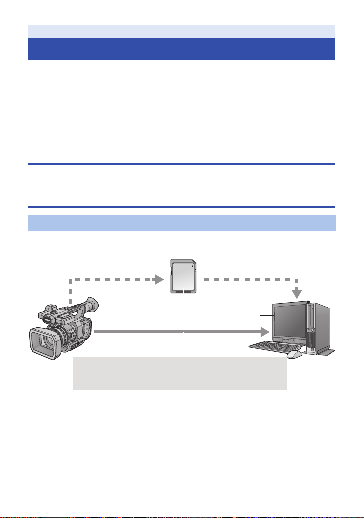
A SDHC Memory Card/SDXC Memory Card*
2
B USB 3.0 (Device mode)*
3
C PC
What you can do with this unit
This unit is a 4K*1 camera recorder with the following features:
*1 Please refer to page 142 about recording format of this unit.
≥ The 4/3-type large sensor allows you to record beautifully defocused images with shallow depth
of field as ultra high-definition 4K motion picture.
≥ V-Log L (12 stops) allows you to record expressive images with greater latitude.
≥ Recording at a variable frame rate of up to 120 fps (for FHD) is possible.
≥ It incorporates the 5-Axis Hybrid Image Stabilizer, Custom AF function, and ND filters (1/4, 1/16,
and 1/64).
≥ Supported recording media include SDHC Memory Card and SDXC Memory Card.
Recording to the SD card
A variety of recording functions support recording to the SD card.
≥ This unit supports relay/simultaneous/background/dual codec recording using double card slots.
Linking to external devices
USB Device Mode
Transfer data (files) to perform nonlinear editing on another device (PC, etc.).
≥ This unit supports USB 3.0.
*2 SD cards are optional and not supplied with this unit.
*3 A USB 3.0 cable is not supplied with this unit. Use a commercially-available double-shielded
USB 3.0 cable with a ferrite core.
If possible, we recommend using a cable with a length of 1.5 m (4.9 feet) or less.
- 6 -
Page 7
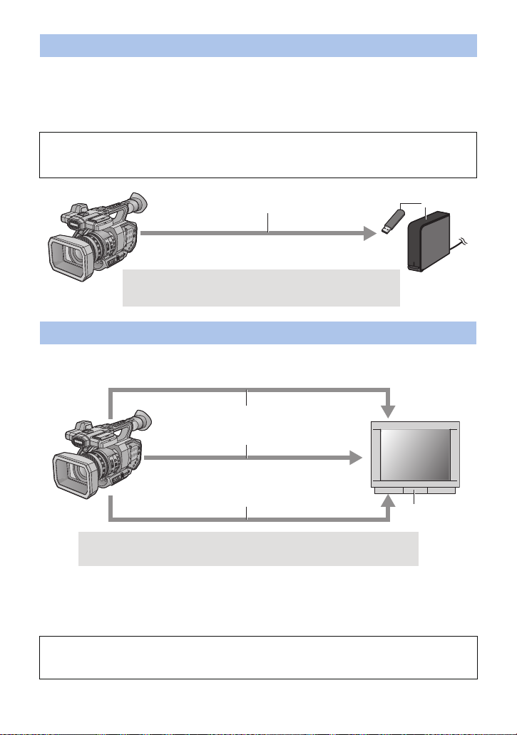
USB Host Mode
A USB 3.0 (Host mode)
B External media device (commercially-available)
A Audio cable*
1
B HDMI cable*
2
C BNC cable*
3
D External monitor
If you connect an external media device, such as USB HDD or USB flash memory (commerciallyavailable) to this unit, you can copy motion pictures and still pictures recorded on this unit to the
external media device.
It can also play back the scenes and still pictures copied to the external media device.
≥ This unit supports USB 3.0.
Refer to the following support site for information about an external media device.
http://pro-av.panasonic.net/
(This Site is English only)
Connecting to an external monitor
Connect an external monitor to output images.
≥ It is also possible to output 4:2:2 (10 bit) images, depending on the [OUTPUT BITS] setting.
*1 Use a commercially-available audio cable (3.5 mm (0.14 q) diameter jack to RCA cable).
*2 Use a commercially-available High Speed HDMI cable.
If possible, we recommend using a cable with a length of 3 m (9.84 feet) or less.
*3 To connect to the SDI OUT or VIDEO OUT terminal, use a double-shielded BNC cable
equivalent to 5C-FB (commercially-available).
When connecting with an HDMI cable using an HDMI-to-DVI converter, etc., be sure to
connect the HDMI cable to the connector of this unit last.
Connecting the HDMI cable to the connector of this unit first may result in malfunction.
- 7 -
Page 8
Preparation
4
7
6
9
8
10
11
12
13
14
15
18
17
16
23
22
20
19
21
24
5
3
1
2
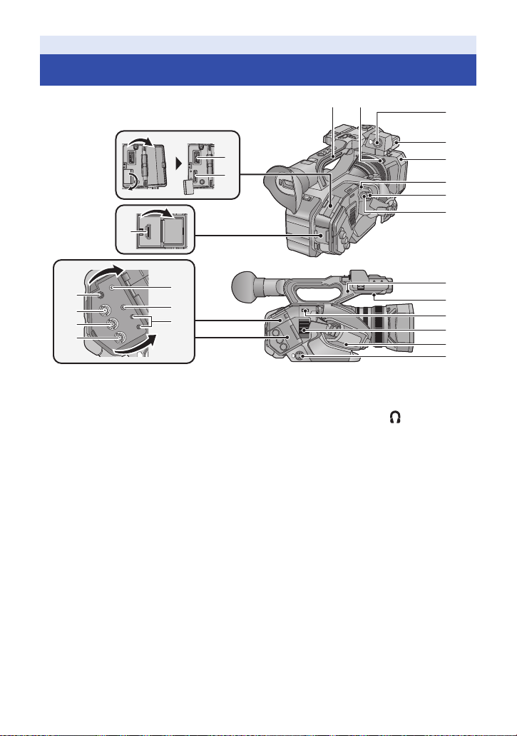
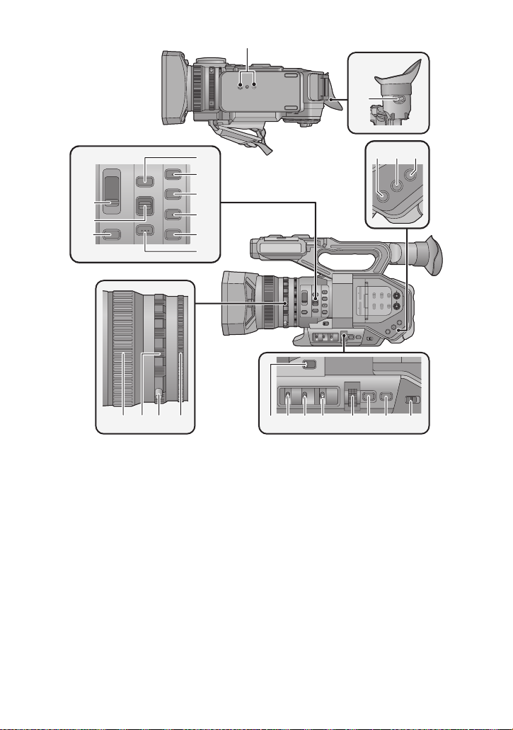
Names and Functions of Main Parts
1 USB HOST terminal (l 125)
2 USB DEVICE terminal (l 122)
3 HDMI OUT connector [HDMI] (l 114 )
4 Handle
5 Lens hood release button (l 12)
6 Audio input terminal 1 (XLR 3 pin)
[AUDIO INPUT1] (l 14, 67)
7 Microphone holder attachment part
(l 14)
8 Lens hood (l 12)
9 Status indicator (l 23)
10 Power switch (l 23)
11 Recording start/stop button (l 33)
12 DC input terminal [DC IN] (l 20)
≥ Do n ot use any other AC adapto rs except the
supplied one.
13 SDI OUT terminal (l 114 )
14 TC PRESET IN/OUT terminal (l 73)
15 VIDEO OUT terminal (l 114)
16 Headphone terminal [ ] (l 100, 113)
≥
Excessive sound pressure from earphones
and headphones can cause hearing loss.
≥ Listening at full volume for long periods may
damage the user ’s ears.
17 AUDIO OUT terminal (l 114)
18 Camera remote terminal [CAM
REMOTE] (l 113)
≥ FOCUS IRIS terminal (3.5 mm (0.14 q)
diameter mini jack)
≥ ZOOM S/S terminal (2.5 mm (0.1 q) diameter
super mini jack)
19 Pin holder
≥ Attaches the zoom ring pin removed from this
unit.
20 Speaker
21 Shoulder strap fixture (l 13)
22 Inlet (cooling fan) (l 31)
23 Hand strap (l 13)
24 Audio input terminal 2 (XLR 3 pin)
[AUDIO INPUT2] (l 14, 67)
- 8 -
Page 9
25
26
30
31
27
28
29
32
33
34
35
36 37 3938
25 Tripod receptacle (l 14)
26 Eyepiece corrector lever (l 27)
27 ND filter switch [ND FILTER] (l 96)
28 Focus auto/Manual/¶ switch
[FOCUS A/M/¶] (l 44)
29 Iris button [IRIS] (l 59)
30 FOCUS ASSIST button (l 48)
31 User 1 button [USER1] (l 74)
32 User 2 button [USER2] (l 74)
33 User 3 button [USER3] (l 74)
34 User 4 button [USER4] (l 74)
35 PUSH AUTO button (l 44)
36 Focus ring (l 44)
37 Zoom ring (l 40)
38 Zoom ring pin
39 Iris ring (l 59)
424140
454443 46 47 48 49 50
40 User 5 button [O.I.S.] (l 42, 74)
41 User 6 button [ZEBRA] (l 74, 88)
42 User 7 button [WFM] (l 74, 87)
43 Zoom switch [MANU/SERVO] (l 40)
44 D
i
splay/Mode check switch [DISP/
MODE CHK] (l 75, 96)
45 Gain switch [GAIN] (l 61)
46 White Balance switch [WHITE BAL]
(l 55)
47 Jog dial [SEL/PUSH SET] (l 55, 61, 63,
98, 103)
48 Menu button [MENU] (l 30)
49 Shutter speed button [SHUTTER] (l 63)
50 Auto/Manual switch [AUTO/MANU]
(l 36)
- 9 -
Page 10
595756 58
51
61
60
63 64 66 676562
5352
5554
68
69
70
72
71
75
74
77
78
76
73
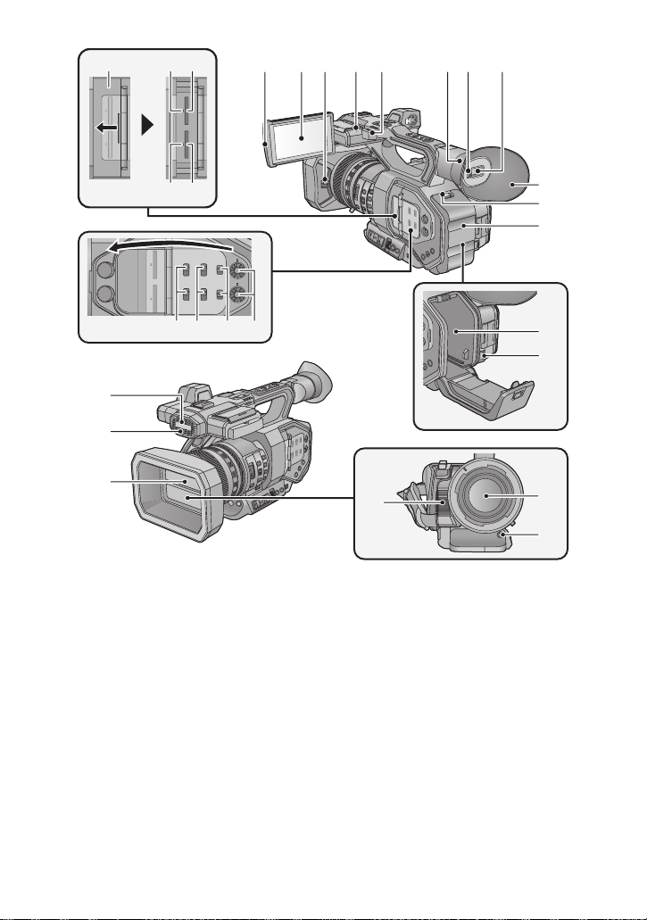
51 SD Card slot cover (l 22)
52 Access lamp (card 1) (l 22)
53 Card slot 1 (l 22)
54 Access lamp (card 2) (l 22)
55 Card slot 2 (l 22)
56 INPUT1 / INPUT2 switches (l 66)
57 CH1 SELECT/CH2 SELECT switches
(l 66)
58 CH1/CH2 switches (l 66)
59 AUDIO LEVEL CH1/AUDIO LEVEL CH2
knobs (l 68)
60 LCD monitor extract part (l 24)
61 LCD monitor (Touch screen) (l 25)
62 Lens cover open/close lever (l 12)
63 Recording lamp (Rear) (l 177)
64 Shoulder strap fixture (l 13)
65 Eye cup mount (l 13)
66 Eye sensor (l 28)
67 Viewfinder (l 27)
68 Eye cup (l 13)
69 Open/close lever [OPEN] (l 17)
70 Battery cover (l 17)
71 B
ttery holder (l 17)
a
72 Battery release lever [BATTERY] (l 17)
73 Built-in microphone
74 Recording lamp (Front) (l 177)
75 Lens cover (l 12)
76 Exhaust opening (cooling fan) (l 31)
77 Lens (LEICA DICOMAR)
78 Auto white balance button [AWB] (l 55)
- 10 -
Page 11
79 80 81 82 83
84 85 86 87
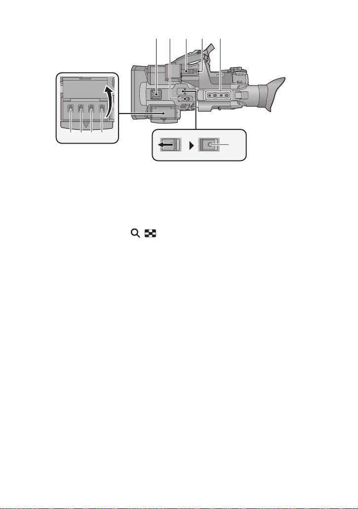
79 Accessory shoe
80 Sub zoom lever (l 40, 156)
≥ This lever functions in the same manner as
the zoom lever.
81 Zoom lever [T/W] (In Recording Mode)
(l 40)
Volume lever [rVOLs]/
Thumbnail display switch [ / ] (In
Playback Mode) (l 103)
82 User 8 button [REC CHECK] (l 74, 80)
83 Handle mounting hole
(Size of the mounting hole)
j
1/4-20UNCk2
j 3/8-16UNCk2
84 Thumbnail button [THUMBNAIL] (l 23)
85 Counter button [COUNTER] (l 70)
86 Counter reset/Time code setting button
[RESET/TC SET] (l 72, 73)
87 Color Bar Screen button [BARS] (l 95)
88 Sub recording start/stop button (l 156)
≥ This button functions in the same manner as
the recording start/stop button.
88
- 11 -
Page 12
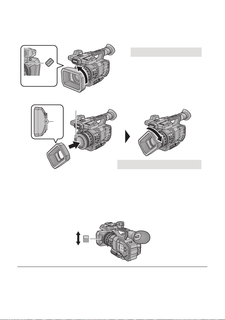
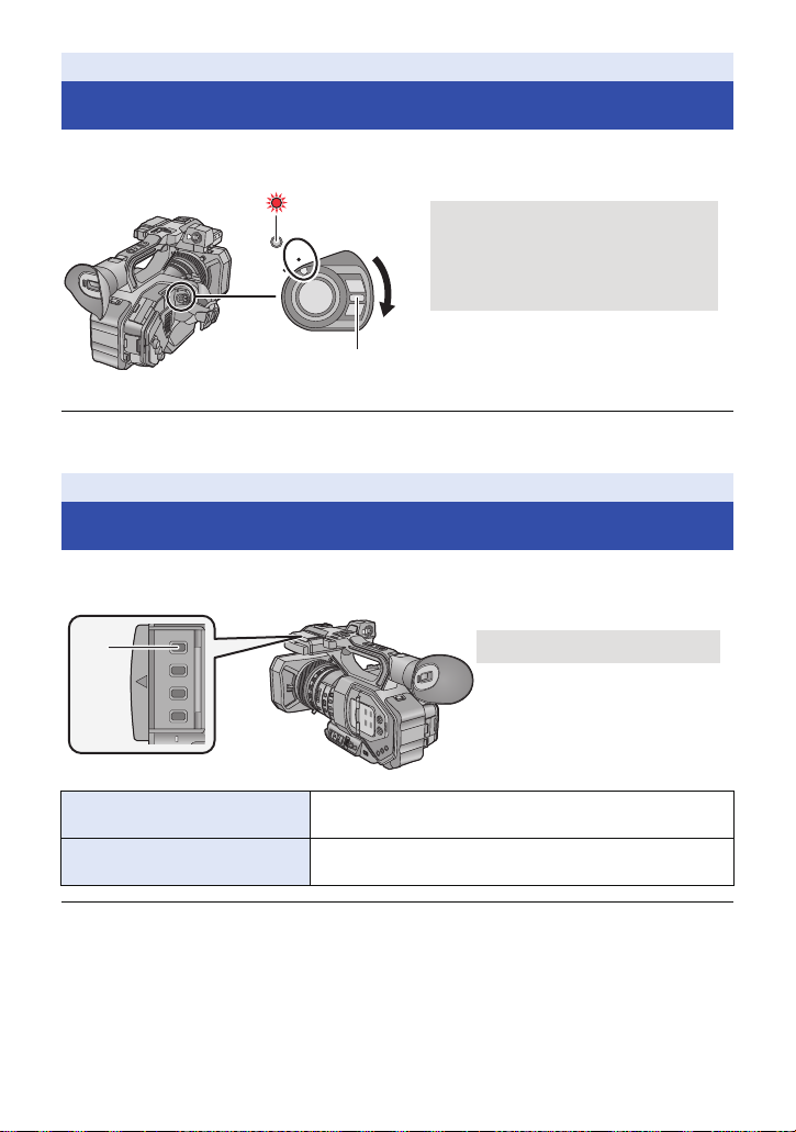
∫ Attaching/detaching the lens hood
A Lens hood release button
B Mounting mark
OPEN
CLOSE
(How to detach the lens hood)
While pressing and holding the lens hood release button, rotate the lens hood in
the direction of the arrow to detach it.
(How to attach the lens hood)
1 Fit the lens hood into this unit.
≥ Align the mounting mark on the lens hood with the mounting mark on this unit.
2 Rotate the lens hood in the direction of the arrow.
≥ Rotate until it clicks into place.
Opening/closing the lens cover
You can open/close the lens cover by sliding the lens cover open/close lever.
≥ When this unit is not in use, close the lens cover to protect the lens.
≥ Do not press the lens cover hard. This may damage the lens or the lens cover.
≥ Depending on the various filters or the MC protector attached to the front side of this unit's lens,
you may not be able to open/close the lens cover or attach the lens hood.
- 12 -
Page 13
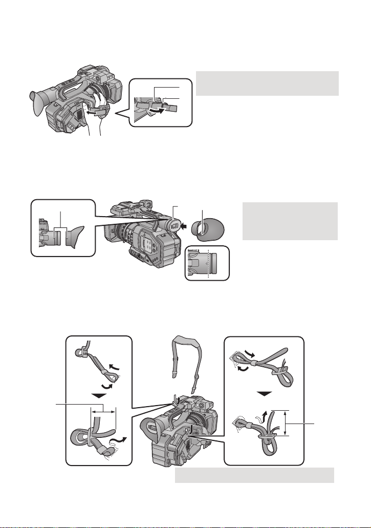
∫ Adjust the length of the hand strap so that it fits your hand.
1 Open the buckle.
2 Pull the end of the belt.
A Mounting marks
B Notch
C Protrusion
A 20 mm (0.8 q) or longer
Adjust the hand strap according to the size of your hand.
≥ If you find it difficult to fasten the buckle B, move the pad A towards you, and fasten the buckle
B again.
∫ Attaching the eye cup
1 Align the mounting mark on the eye cup mount with the corresponding mark on
the eyecup.
2 Attach the eye cup so that the notch on the eye cup mount is aligned with the
protrusion inside the eye cup.
≥ Push the eye cup in until it reaches the mounting mark. (D)
∫ Attaching the Shoulder strap
We recommend that you attach the shoulder strap (supplied) before going out of doors to record so
as to avoid dropping this unit.
- 13 -
Page 14
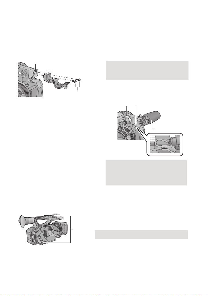
∫ Attaching the front microphone
A Microphone holder attachment part
B Microphone holder
C Microphone holder mounting screws
D AUDIO INPUT1 terminal (XLR 3 pin)
E Microphone cable clamper
F Microphone holder screw
G External microphone (optional)
A INPUT terminal cap
≥ The microphone holder is set up so that a 21 mm (0.83 q) external microphone (AG-MC200G:
optional) can be attached. Check in advance whether the microphone you wish to use can be
attached.
1 Attach the microphone holder to the microphone holder attachment part.
≥ Attach by using a commercially available screw driver.
≥ When attaching the microphone holder, be sure to tighten the screws firmly even though you
might hear a squeaking sound.
2 Attach an external microphone
(optional) to the microphone holder,
and tighten the microphone holder
screw.
3 Connect the external microphone to
the AUDIO INPUT1 terminal (XLR 3
pin).
≥ When wiring the microphone cable, use the
cable clamper of this unit.
≥ Keep the microphone holder screw, zoom
ring pin and INPUT terminal cap out of reach
of children to prevent swallowing.
∫ Attaching the INPUT terminal cap
Attach the INPUT terminal cap while the AUDIO INPUT1, 2 terminals (XLR 3 pin) are not used.
∫ Attaching the tripod
≥ There are tripod mounting holes that are compatible with 1/4-20UNC and 3/8-16UNC screws.
Use the size that matches the diameter of the tripod’s fixing screw.
- 14 -
Page 15

≥ Attaching a tripod with a screw length of 5.5 mm (0.22 q) or more may damage the unit.
A Tripod receptacle
Preparation
Power supply
∫ About batteries that you can use with this unit (as of August 2015)
The battery that can be used with this unit is VW-VBD58.
It has been found that counterfeit battery packs which look very similar to the genuine
product are made available to purchase in some markets. Some of these battery packs
are not adequately protected with internal protection to meet the requirements of
appropriate safety standards. There is a possibility that these battery packs may lead to
fire or explosion. Please be advised that we are not liable for any accident or failure
occurring as a result of use of a counterfeit battery pack. To ensure that safe products are
used we would recommend that a genuine Panasonic battery pack is used.
- 15 -
Page 16
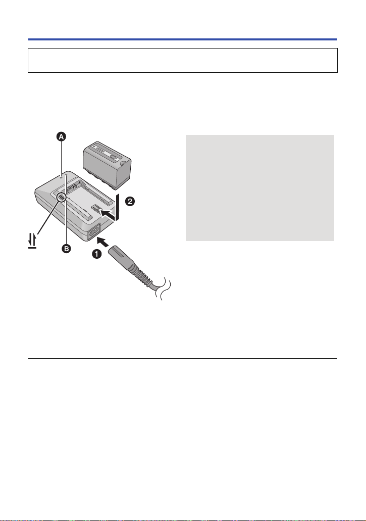
Charging the battery
Charging lamp [CHARGE] A
Lights up:
Charging (Battery charging time: l 18)
Goes off:
Charging completed
Flashing:
Be sure to connect the unit correctly (l 196)
Power lamp [POWER] B
≥ This will light up when the AC cable is
connected.
When this unit is purchased, the battery is not charged. Charge the battery fully before
using this unit for the first time.
Important:
≥ Do not use the AC cable with any other equipment as it is designed only for this unit. Also,
do not use the AC cable from other equipment with this unit.
≥ It is recommended to charge the battery in a temperature between 10 oC and 30 oC (50 oF
and 86 oF). (The battery temperature should also be the same.)
≥ Insert the plugs as far as they will go.
1 Connect the AC cable to the battery charger and the AC outlet.
2 Insert the battery into the battery charger by aligning the arrows.
≥ We recommend using Panasonic batteries (l 18).
≥ If you use other batteries, we cannot guarantee the quality of this product.
≥ Do not heat or expose to flame.
≥ Do not leave the battery(ies) in a car exposed to direct sunlight for a long period of time with
doors and windows closed.
- 16 -
Page 17
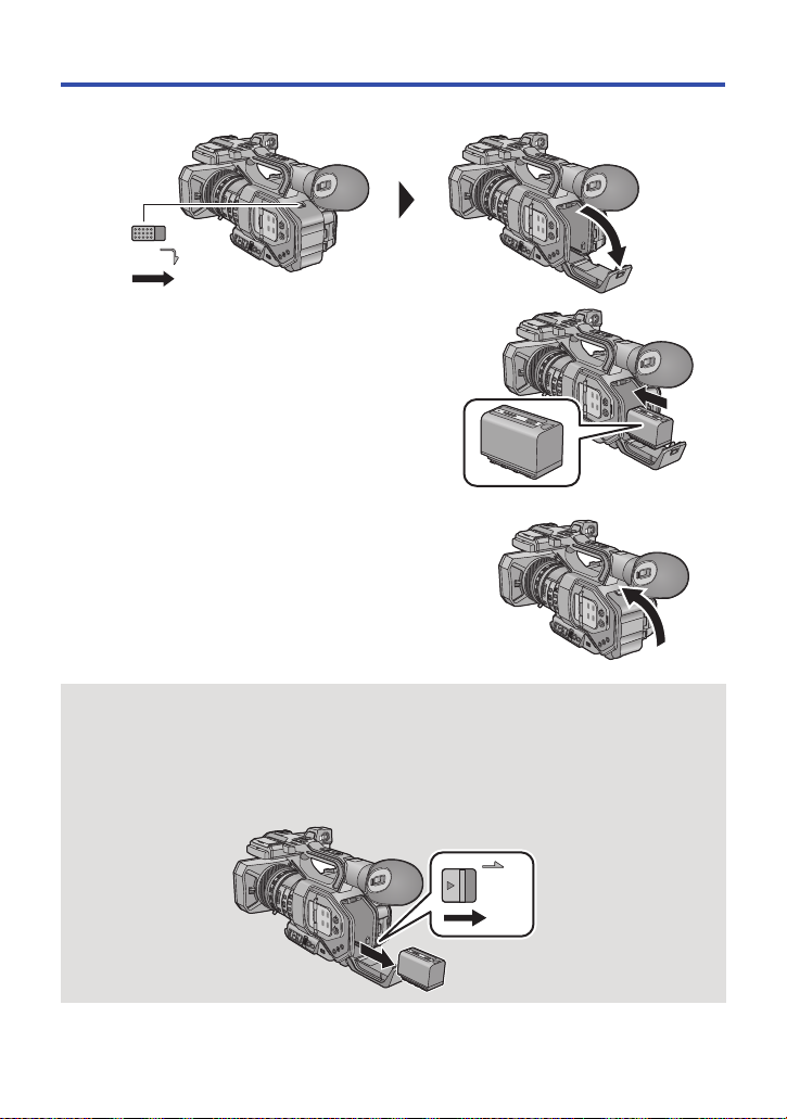
Inserting/removing the battery
ャモヵヵユンヺ
1 Slide the open/close lever, and open the battery cover.
ヰヱユワ
2 Install the battery by inserting it in the
direction shown in the figure.
≥ Insert the battery until it clicks and locks.
3 Close the battery cover.
≥ Close the battery cover until it clicks and locks.
Removing the battery
Make sure that the power switch is set to OFF and the status indicator is turned off, and then
remove by holding onto it taking care not to drop. (l 23)
Open the battery cover, and slide the battery release lever.
≥ The battery will be unlocked, allowing you to take it out.
≥ Slide the battery release lever in the direction indicated by the arrow.
- 17 -
Page 18

Charging and recording time
Charging/Recording time
Battery model number
Supplied battery/
VW-VBD58 (optional)
≥ The times given apply when the ambient operating temperature is 20 o C (68 oF) and the relative
operating humidity is 60%. Charging time may be longer at other temperatures and humidity
levels.
≥ The continuous recordable time given applies under the conditions below. The time becomes
shorter under other conditions.
j The LCD monitor is open
j A cable is not inserted to the external output terminal
≥ “h” is an abbreviation for hour, “min” for minute and “s” for second.
≥ These times are approximations.
≥ The indicated charging time is for when the battery has been discharged completely.
Charging time and recordable time vary depending on the usage conditions such as high/
low temperature.
≥ The batteries heat up after use or charging. This is not a malfunction.
Voltage/Capacity
(minimum)
7.2 V/5800 mAh 380 min 150 min
Charging time
Continuously recordable
time
- 18 -
Page 19
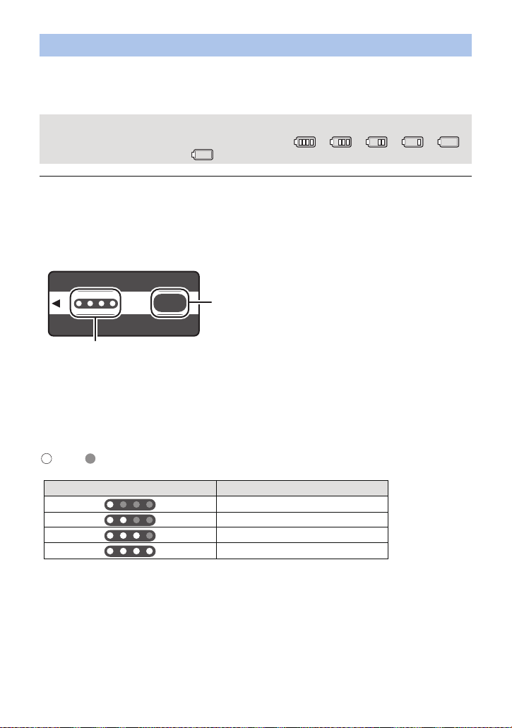
Checking the remaining power of the battery
CHECK
LED lamp status Remaining power of the battery
0% to 25%
25% to 50%
50% to 75%
75% to 100%
You can check the remaining power of the battery by looking at the battery capacity indication
displayed on this unit's screen or by looking at the supplied battery VW-VBD58.
∫ Checking the remaining power using this unit
Battery capacity indication
≥ The display changes as the battery capacity reduces. ####
If the battery discharges, then will flash red.
≥ Depending on the menu setting, the battery capacity indication is not displayed (l 174)
[DISP SETUP] # [CARD & BATTERY]
∫ Checking the remaining power using the battery
If you press the CHECK button, the remaining power indicator (LED lamp) lights up green, allowing
you to check the remaining power of the battery.
CHECK
0
100
%
A CHECK button
B Remaining power indicator
≥ The remaining power of the battery is an approximate guide.
≥ When the LED lamp does not light up even if you press the CHECK button, the battery is
exhausted. Charge the battery.
How to read the remaining power indicator
:Lit up/ :Off
≥ The display of the remaining power indicator is an approximate guide for the remaining power of
the battery. When the battery pack is connected to the video camera or the charger, refer to the
remaining power display of the connected device. The display of the connected device may differ
from that of the battery pack’s remaining power indicator.
- 19 -
Page 20
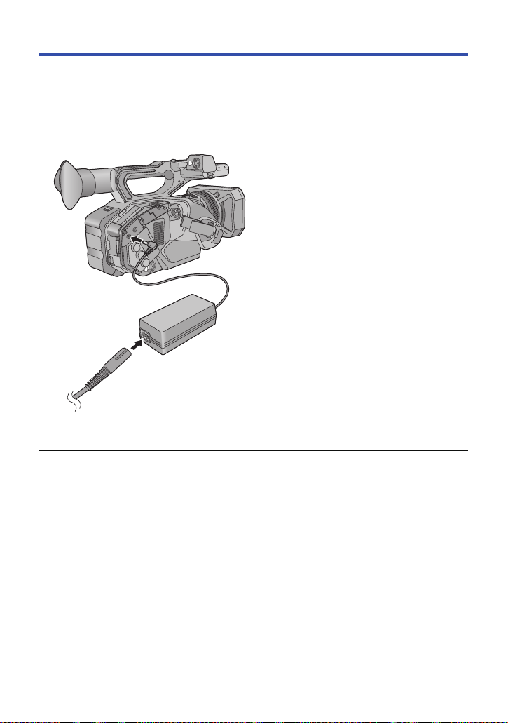
Connecting to the AC outlet
The unit is in the standby condition when the AC adaptor is connected. The primary circuit is always
“live” as long as the AC adaptor is connected to an electrical outlet.
Important:
≥ Use the supplied AC adaptor. Do not use the AC adaptor of another device.
≥ Do not use the AC cable with any other equipment as it is designed only for this unit. Also,
do not use the AC cable from other equipment with this unit.
1 Connect the AC cable to the AC
adaptor and the AC outlet.
2 Connect the AC adaptor to the DC
input terminal [DC IN].
≥ Make sure to set the power switch to OFF and
the status indicator is turned off when
≥ Insert the plugs as far as they will go.
disconnecting the AC adaptor. (l 23)
≥ Even when you use the AC adaptor for recording images, keep the battery connected. This
allows you to continue the recording even if a power failure occurs or the AC adaptor is
unplugged from the AC outlet by accident.
- 20 -
Page 21
Preparation
64
Preparation of SD cards
The unit can record motion pictures or still pictures to an SD card.
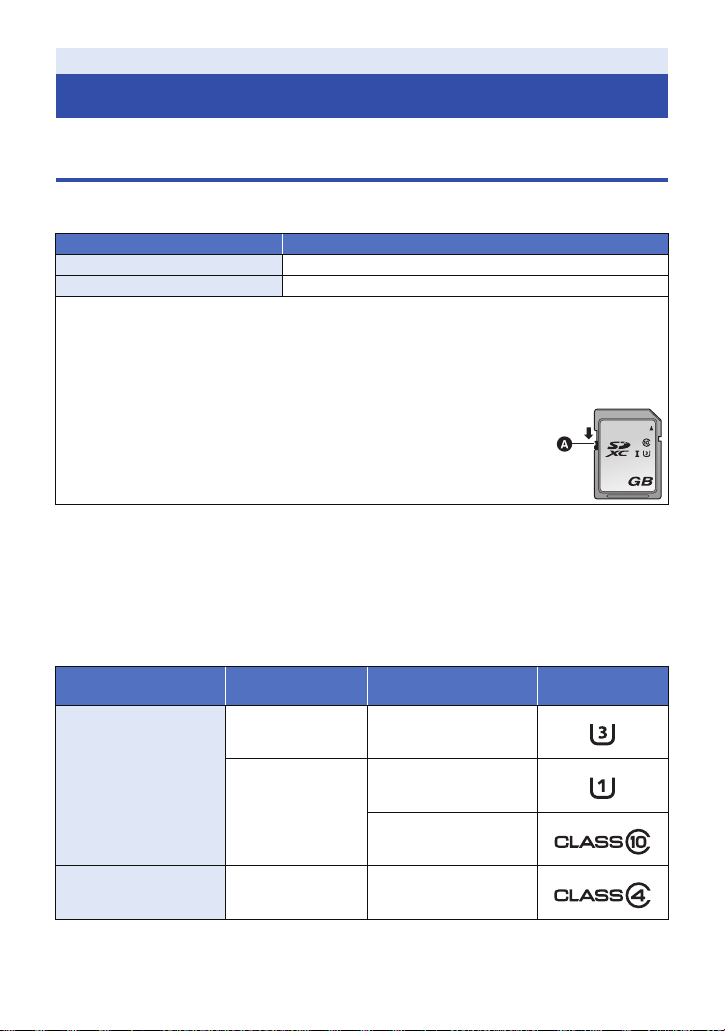
Cards that you can use with this unit
≥ The cards that you can use are correct as of August 2015.
≥ We recommend that you use a Panasonic Memory Card.
Card type Capacity
SDHC Memory Card 4GB to 32GB
SDXC Memory Card 48 GB to 128 GB
≥ When using an SDHC Memory Card/SDXC Memory Card with other equipment, check the
equipment is compatible with these Memory Cards.
≥ We do not guarantee the operation of SD cards other than the ones above.
≥ 4 GB or more Memory Cards that do not have the SDHC logo or 48 GB or more Memory Cards
that do not have the SDXC logo are not based on SD Memory Card Specifications.
≥ This unit is compatible with UHS-
≥ When the write-protect switch A on SD card is locked, no recording,
deletion or editing will be possible on the card.
≥ Keep the Memory Card out of reach of children to prevent swallowing.
∫ About the Speed Class ratings for recording motion pictures
≥ Depending on [REC MODE] (l 141) and [REC FORMAT] (l 142), the required card differs.
Use a card that meets the following ratings of the SD Speed Class or UHS Speed Class.
Use of a non-compatible card may cause recording to stop suddenly.
≥ SD Speed Class and UHS Speed Class are the speed standards regarding continuous writing. To
check the class, see the labelled side, etc. of the card.
≥ We recommend that you use an SD card compatible with UHS Speed Class3 when recording in
Variable Frame Rate Mode.
Recording modes
I UHS Speed Class3 standard SDHC/SDXC Memory Cards.
Bit rates in
[REC FORMAT]
Speed Class ratings Label examples
100 Mbps or more UHS Speed Class3*
MOV/MP4
50 Mbps
AVCHD All Class4 or more
* When [UHD 2160/59.94p 150M] or [UHD 2160/50.00p 150M] is selected, an SDXC Memory Card
with a capacity of 64 GB or more and a Speed Class rating of UHS Speed Class3 is required.
UHS Speed Class1 or
more
Class10 or more
- 21 -
Page 22
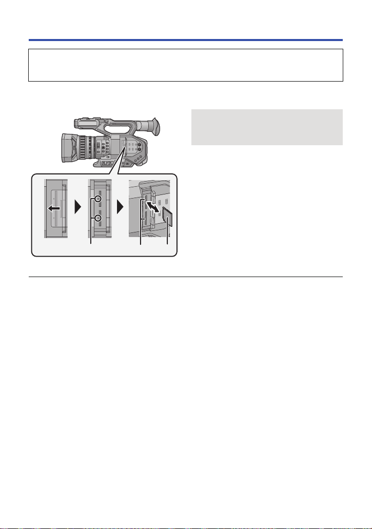
Inserting/removing an SD card
When using an SD card for the first time, it is necessary to format the SD card. (l 32) When the
SD card is formatted, all of the recorded data is deleted. Once the data is deleted, it cannot be
restored.
Caution:
Check that the access lamp has gone off.
Access lamp A
≥ When this unit is accessing the SD card,
the access lamp lights up.
1 Open the SD card slot cover and
insert (remove) the SD card into
(from) the card slot B.
≥ One SD card can be inserted into each of the
card slot 1 and the card slot 2.
≥ Face the terminal side C in the direction
shown in the illustration and press it straight
in as far as it will go.
≥ Press the center of the SD card and then pull
it straight out.
2 Securely close the SD card slot
cover.
≥ Do not touch the terminals on the back of the
SD card.
≥ Do not apply strong shocks, bend, or drop the
SD card.
≥ Electrical noise, static electricity or the failure
of this unit or the SD card may damage or
erase the data stored on the SD card.
≥ When the card access lamp is lit, do not:
j Remove the SD card
j Turn the unit off
j Insert and remove the USB Cable
j Expose the unit to vibrations or shock
Performing the above while the lamp is on
may result in damage to data/SD card or this
unit.
≥ Do not expose the terminals of the SD card to
water, dirt or dust.
≥ Do not place SD cards in the following areas:
j In direct sunlight
j In very dusty or humid areas
j Near a heater
j Locations susceptible to significant
difference in temperature (condensation
can occur.)
j Where static electricity or electromagnetic
waves occur
≥ To protect SD cards, return them to their
cases when you are not using them.
≥ About disposing of or giving away the SD
card. (l 196)
- 22 -
Page 23
Preparation
ON
OFF
To turn off the unit
Set the power switch to OFF while
pressing the lock release button.
The status indicator goes off.
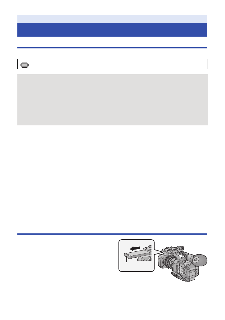
A THUMBNAIL button
Turning the unit on/off
Set the power switch to ON while pressing the lock release button B to turn on
the unit.
A The status indicator lights on.
≥ To turn on the unit again after the [ECONOMY (BATT)] or [ECONOMY (AC)] is activated, set the
power switch to OFF once, and then to ON again. (l 177)
Preparation
Selecting a mode
Press the THUMBNAIL button to change the mode to Recording Mode or
Playback Mode.
Recording Mode (l 33, 34) The recording screen is displayed. You can record motion
Playback Mode (l 101) The thumbnail screen for playback is displayed. You can play
≥ When you turn on this unit, it starts up in Recording Mode.
≥ If you press the recording start/stop button or sub recording start/stop button in Playback Mode,
the mode will be switched to Recording Mode and recording will start.
pictures and still pictures.
back motion pictures and still pictures.
- 23 -
Page 24
Preparation
MENU
Using the LCD monitor/Viewfinder
Setting how to turn on/off the LCD monitor and Viewfinder
Select the menu. (l 30)
: [OUTPUT SETUP] # [LCD/EVF OUTPUT] # desired setting
[AUTO]: The LCD monitor is turned on when the LCD monitor is extracted. When you move
[LCD]: The LCD monitor is turned on when the LCD monitor is extracted. The viewfinder is
[EVF]: The viewfinder turns on when you move your eye closer to the eye cup of the
your eye closer to the eye cup of the viewfinder, the LCD monitor is turned off, and
the viewfinder is turned on.
not turned on.
viewfinder and turns off when you move your eye away from it. The LCD monitor
does not turn on.
∫ To change the setting with a USER button
You can change how to turn on/off the LCD monitor and Viewfinder by registering “LCD/EVF
Output” to a USER button.
≥ Please refer to page 74 for details about setting the USER button.
When the recording screen is displayed, press the USER button to which [LCD/
EVF OUTPUT] is registered or touch the applicable USER button icon.
≥ Switches the setting each time the button is pressed.
[AUTO] # [LCD] # [EVF]
≥ The setting is also applied to the [LCD/EVF OUTPUT] menu setting.
≥ The viewfinder turns on as soon as [EVF] is selected and stays on. It reacts to the eye sensor and
turns on/off only after you move your eye closer to the eye cup of the viewfinder.
≥ Depending on the shape of your glasses or the way you hold this unit, or when bright light enters
the eyepiece, the eye sensor may not work correctly.
≥ You can turn on/off the viewfinder by registering [EVF ON/OFF] to a USER button.
Using the LCD monitor
1 Extract the LCD monitor in the
direction as indicated in the figure.
≥ Hold the LCD monitor extract part A, and
extract the LCD monitor until it clicks into
position.
- 24 -
Page 25
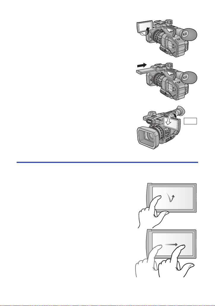
2 Rotate to the position that is easy to view.
270°
To retract the LCD monitor
Retract as shown in the figure with the LCD facing
downward.
Range of rotation of the LCD monitor
≥ It can rotate up to 270o towards the lens.
How to use the touch screen
You can operate by directly touching the LCD monitor (touch screen) with your finger.
∫ Touch
Touch and release the touch screen to select icon or
picture.
≥ Touch the center of the icon.
≥ Touching the touch screen will not operate while you
are touching another part of the touch screen.
∫ Slide while touching
Move your finger while pressing on the touch screen.
- 25 -
Page 26
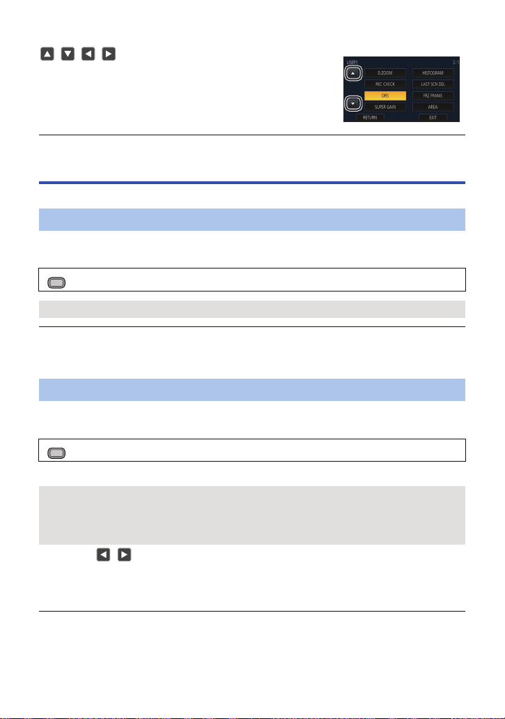
∫ About the operation icons
///:
Touch when changing a page or performing settings.
≥ Do not touch the LCD monitor with hard pointed tips, such as ball point pens.
LCD monitor adjustment
≥ These settings will not affect the images actually recorded.
[LCD BACKLIGHT]
Brightness of the LCD monitor can be switched.
Select the menu. (l 30)
MENU
: [DISP SETUP] # [LCD BACKLIGHT] # desired setting
[HIGH]/[LOW]
≥ [LOW] is selected when:
j [USB MODE SELECT] is set to [DEVICE] and this unit is connected to a PC. (l 122)
≥ When the [LCD/EVF OUTPUT] is set to [EVF], this item cannot be set. (l 24)
[LCD SET]
It adjusts brightness and color density on the LCD monitor.
1 Select the menu. (l 30)
MENU
: [DISP SETUP] # [LCD SET]
2 Touch the desired setting item.
[COLOR]: Color level of the LCD monitor
[BRIGHTNESS]: Brightness of the LCD monitor
[CONTRAST]: Contrast of the LCD monitor
3 Touch / to adjust settings.
≥ You can select a value between s16 and r16.
4 Touch [RETURN].
≥ Touch [EXIT] to exit the menu screen.
≥ When the [LCD/EVF OUTPUT] is set to [EVF], this item cannot be set. (l 24)
- 26 -
Page 27
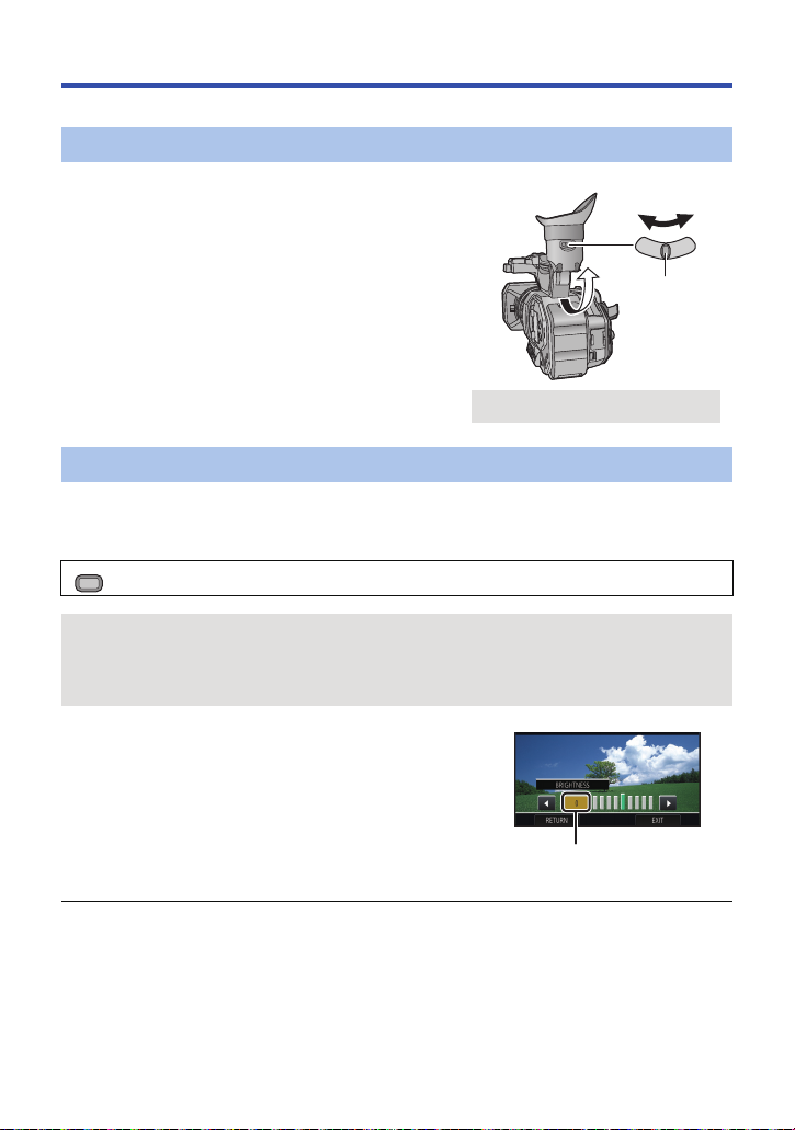
Viewfinder adjustment
A Eyepiece corrector lever
≥ These settings will not affect the images actually recorded.
Adjusting the field of view
It adjusts the field of view to show the image on the viewfinder clearly.
1 Adjust the viewfinder to suit your vision so
that you can see the display images clearly.
≥ Be careful not to trap your fingers when moving the
viewfinder.
≥ The viewfinder can be lifted vertically up to
approximately 90o.
≥ Turn on the viewfinder.
2 Adjust the focus by operating the eyepiece
corrector lever.
[EVF SETTING]
It adjusts brightness and color density of the viewfinder.
≥ Use the jog dial to change the settings. (l 98)
1 Select the menu. (l 30)
MENU
: [DISP SETUP] # [EVF SETTING] # desired setting
[COLOR]: Color level of the viewfinder
[BRIGHTNESS]: Brightness of the viewfinder
[CONTRAST]: Contrast of the viewfinder
2 Rotate the jog dial to move the cursor to the
value display A.
≥ Push the jog dial to select the value display.
3 Rotate the jog dial to adjust the setting.
≥ Pushing the jog dial will set the value you have selected.
≥ You can select a value between s16 and r16.
4 Select [RETURN].
≥ Select [EXIT].
≥ When the [LCD/EVF OUTPUT] is set to [LCD], this item cannot be set. (l 24)
≥ When [COLOR] is set to s16, images are displayed in black and white.
- 27 -
Page 28
[EVF COLOR]
The recording images or playback images on the viewfinder can be selected between color/black
and white.
Select the menu. (l 30)
MENU
: [DISP SETUP] # [EVF COLOR]# [ON] or [OFF]
[ON]: Displayed in color
[OFF]: Displayed in black and white
≥ If you adjust the [COLOR] setting in [EVF SETTING], [EVF COLOR] will be set to [ON].
[EYE SENSOR]
It adjusts sensitivity of eye sensor.
1 Select the menu. (l 30)
MENU
: [DISP SETUP] # [EYE SENSOR]
2 Touch / to adjust settings.
≥ You can select a value between s4 and r4.
3 Touch [EXIT] to complete the setting.
≥ When the [LCD/EVF OUTPUT] is set to [LCD], this item cannot be set. (l 24)
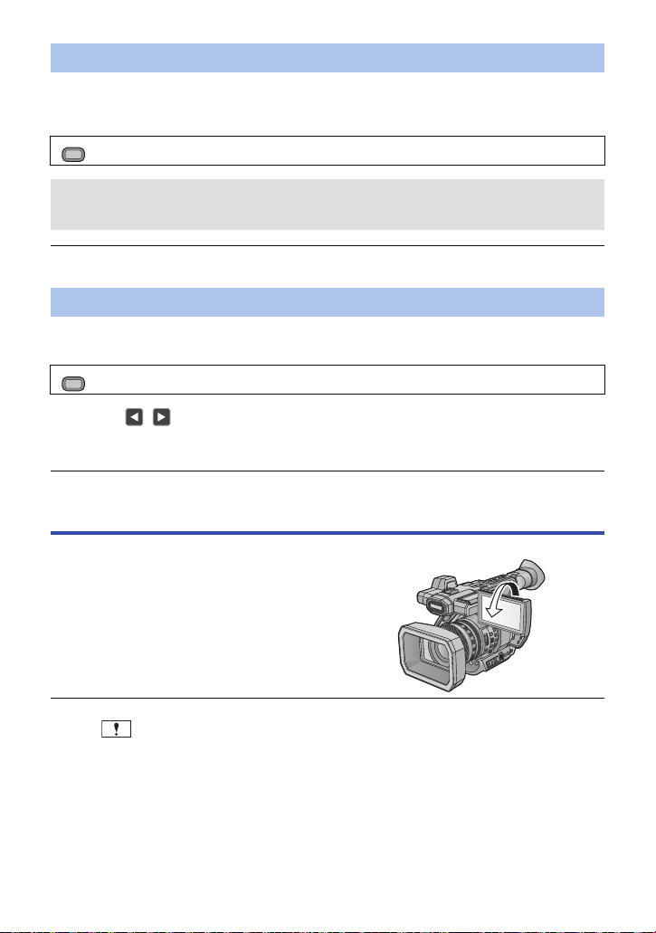
Recording yourself
≥ Change the mode to Recording Mode. (l 23)
Rotate the LCD monitor towards the lens side.
≥ Displaying during the recording yourself can be
switched by setting [SELF SHOOT]. (l 175)
≥ Only some indications will appear on the screen when the [SELF SHOOT] is set to [MIRROR].
When appears, return the direction of the LCD monitor to normal position and check the
warning/alarm indication. (l 185)
≥ The LCD monitor display changes as follows when Self Shoot is used:
j The viewfinder image is displayed.
j The display size becomes smaller.
- 28 -
Page 29
Preparation
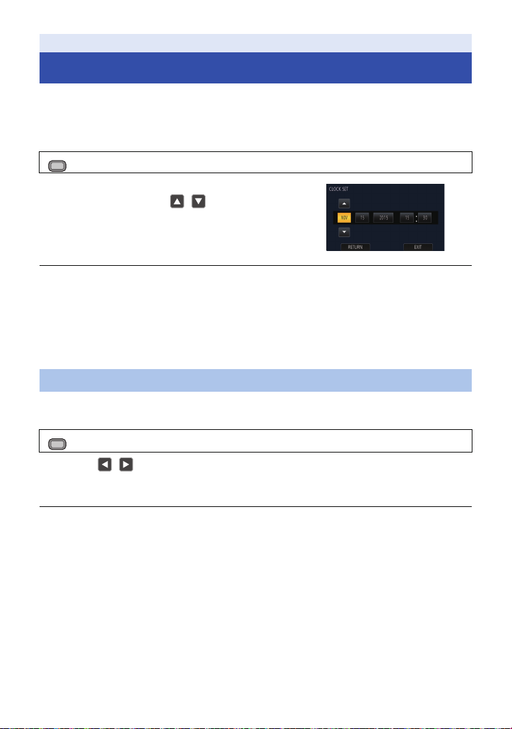
Setting date and time
When this unit is turned on, the message [SET TIME ZONE AND DATE/TIME] may appear.
To make these settings, select [YES], and follow the instructions from Step 2-3 of the time zone
setting procedure.
1 Select the menu. (l 30)
MENU
: [OTHER FUNCTION] # [CLOCK SET]
2 Touch the date or time to be set, then set the
desired value using / .
≥ The year can be set between 2000 and 2039.
3 Touch [EXIT] to complete the setting.
≥ The date and time function is driven by a built-in lithium battery.
≥ If the time display becomes [- -], the built-in lithium battery needs to be charged. To recharge the
built-in lithium battery, connect the AC adaptor or attach a charged battery to this unit. Leave the
unit as it is for approx. 24 hours and the battery will maintain the date and time for approx.
6 months. (The battery is still being recharged even if the unit is off.)
≥ The way that time is displayed can be changed in the menu settings. (l 173)
[DISP SETUP] # [DATE/TIME] or [DATE FORMAT]
Time zone
Time difference from the Greenwich Mean Time can be set.
1 Select the menu. (l 30)
MENU
: [OTHER FUNCTION] # [TIME ZONE]
2 Touch / and set the region to record.
3 Touch [EXIT] to complete the setting.
≥ If the [CLOCK SET] screen appears, perform [CLOCK SET].
≥ When the time zone setting is changed, the date/time setting of the unit also changes
automatically.
- 29 -
Page 30
Preparation
MENU
MENU
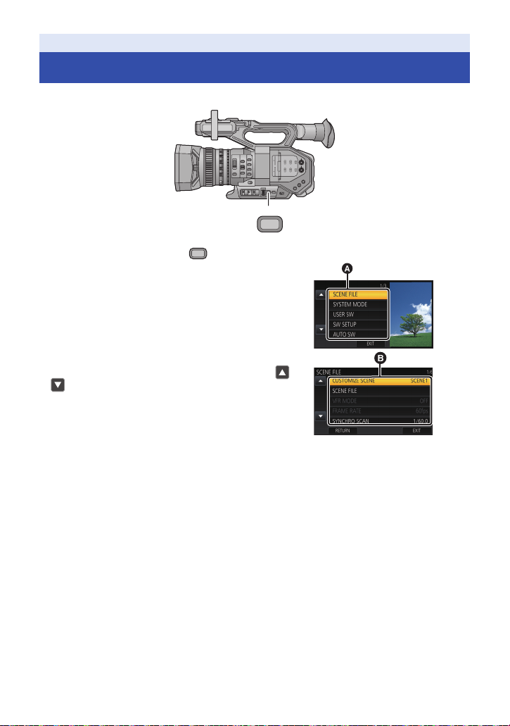
Using the menu screen
≥ You can also select menu items by operating the jog dial. (l 98)
1 Press the MENU button .
2 Touch the top menu A.
3 Touch the submenu B.
≥ Next (Previous) page can be displayed by touching /
.
4 Touch the desired item to enter the setting.
5 Touch [EXIT] to exit the menu setting.
- 30 -
Page 31

Recording
MENU
4:2:2 10bit
Before recording
≥ When recording, make sure your footing is stable and there is no danger of colliding with another
person or object.
≥ Hold the eye cup of the viewfinder as close as possible to your eye.
≥ Adjust the angle of the LCD monitor according to the position in which the unit is held.
≥ When you are outdoors, record pictures with the sunlight behind you. If the subject is backlit, it will
become dark in the recording.
≥ Keep your arms near your body and separate your legs for better balance.
≥ For stable images, it is recommended to use a tripod whenever possible.
≥ Do not block the cooling fan inlet or the exhaust opening with your hand or other objects.
Recording
Selecting the Recording Method
When recording to the SD card with this unit, set [OUTPUT BITS] to [4:2:2(8bit)].
When recording with an external device connected via the HDMI OUT/SDI OUT terminal, you can
change the picture quality of images output to the devi ce by changing the [OUTPUT BITS] setting.
Select the menu.
: [SYSTEM MODE]# [OUTPUT BITS] # desired setting
[4:2:2(10bit)]: Allows you to output high quality images using an HDMI/SDI connection.
[4:2:2(8bit)]: Allows you to output the image being recorded with this unit.
≥ When [4:2:2(10bit)] is selected, and are displayed on the screen.
≥ The setting method of the picture quality of the image changes depending on the [OUTPUT BITS]
setting.
j When [4:2:2(10bit)] is selected, change the [OUTPUT FORMAT] setting. (l 147)
j When [4:2:2(8bit)] is selected, change the [REC MODE] and [REC FORMAT] settings. (l 141,
142)
≥ This function is not available in the following cases:
j During Freeze Frame (l 81)
j In Variable Frame Rate Mode (l 91)
≥ The following menu items are not available when [4:2:2(10bit)] is selected:
j [VFR MODE] (l 91, 131)
j [REC MODE] (l 141)
j [REC FORMAT] (l 142)
j [SUB REC BUTTON] (l 156)
j [2 SLOTS FUNC.] (l 159)
j [DUAL CODEC REC] (l 161)
This setting is suitable for recording with an external device that supports
HDMI/SDI output. You cannot record these images with this unit.
REC
j [INTERVAL REC] (l 162)
j [PRE-REC] (l 86, 163)
j [TIME STAMP] (l 164)
j [DOWN CONV.] (l 169)
j [VIDEO OUT OSD] (l 115 )
j [MEDIA SELECT] (l 32)
j [MEDIA STATUS] (l 176)
- 31 -
Page 32

≥ The following functions are not available when [4:2:2(10bit)] is selected:
j [DIGITAL ZOOM] (l 79)
j [REC CHECK] (l 80)
j [LAST SCN DEL] (l 80)
Formatting media
If you use the SD cards for the first time for recording with this unit, format the cards.
Please be aware that if a medium is formatted, then all the data recorded on the medium will be
erased and cannot be restored. Back up important data on a PC etc. (l 121)
≥ When using two SD cards, format both SD cards.
1 Select the menu.
MENU
: [OTHER FUNCTION] # [FORMAT MEDIA]
2 Touch [SD CARD 1] or [SD CARD 2].
≥ When formatting is complete, touch [EXIT] to exit the message screen.
≥ Do not turn this unit off or remove the SD card, while formatting. Do not expose the unit to
vibrations or shock.
Use this unit to format media.
Do not format an SD card using any other equipment such as a PC. Otherwise it may not
be possible to use the card on this unit.
Recording
Selecting a media to record
[SD CARD 1] and [SD CARD 2] can be selected separately to record motion pictures or still
pictures.
≥ Set [OUTPUT BITS] to [4:2:2(8bit)]. (l 31)
1 Select the menu.
MENU
: [RECORD SETUP] # [MEDIA SELECT]
2 Touch the media to record motion pictures
or still pictures.
≥ The media is selected separately for motion pictures or
still pictures and is then highlighted in yellow.
3 Touch [EXIT] to complete the setting.
- 32 -
Page 33

Recording
A When you begin recording, REC (red) is
displayed.
TC 00:00:00TC 00:00:00.0000TC 00:00:00.00
59.94p59.94
p
150M150M
R 1h20mR 1h20mR 1h20m
TC 00:00:00.00 Counter display (l 70)
(White) Media where the motion picture is
recorded (l 32)
R1h20m Approximate remaining recordable
time
≥ When the remaining time is less
than 1 minute, R 0h00m flashes
red.
Recording format (l 142)
150M Bit rate (l 142)
Recording mode (l 141)
59.94p Frame rate (l 142)
Recording motion picture with this unit
≥ Before turning on this unit, open the lens cover. (l 12)
≥ Set [OUTPUT BITS] to [4:2:2(8bit)]. (l 31)
1 Change the mode to
Recording Mode. (l 23)
≥ Extract the LCD monitor.
2 Press the recording start/
stop button B to start
recording.
≥ Recording will stop when you press
the recording start/stop button again.
∫ Screen indications in the Recording Mode
REC
OFF
ON
≥ To change the recording method, change [REC MODE] or [REC FORMAT]. (l 141, 142)
≥ The images recorded between pressing the recording start/stop button to start recording and
pressing it again to pause recording become one scene.
≥ When the file size of a recorded scene exceeds one of the following sizes or the recording time
exceeds one of the following lengths of time, the scene will be divided automatically. (Recording
continues.)
j AVCHD scene: approximately 4 GB
j MOV/MP4 scene (when using an SDHC Memory Card): approximately 4 GB or 30 minutes
j MOV/MP4 scene (when using an SDXC Memory Card): approximately 48 GB or 120 minutes
- 33 -
Page 34

≥ (Maximum recordable scenes of a single SD card)
R3000R3000R3000
M
8.3
Recording mode MOV/MP4 AVCHD
Recordable scenes Approx. 89100 Approx. 3900
Different dates (l 108) Approx. 900 Approx. 900
≥ When the SD card contains scenes recorded with [REC MODE] set to [MOV]/[MP4] and still
pictures, the maximum recordable scenes and the maximum recordable scenes on each date will
be smaller than those in the table above.
≥ Number of scenes that can be recorded will be less than above in following cases:
j If you change [REC FORMAT] (l 142)
j When [2 SLOTS FUNC.] is set to [SIMULTANEOUS] or [DUAL CODEC] (l 159)
j During the Interval Recording (l 162)
≥ Please refer to page 200 about approximate recordable time.
Recording
Recording still pictures
≥ Before turning on this unit, open the lens cover. (l 12)
≥ Set [OUTPUT BITS] to [4:2:2(8bit)]. (l 31)
≥ Register [CAPTURE] to a USER button. (l 74)
1 Change the mode to Recording Mode. (l 23)
≥ Extract the LCD monitor.
2 Press the USER button to which [CAPTURE] is registered or touch the
applicable USER button icon to record a still picture.
≥ For information on the locations of the USER buttons and information on USER button icons,
refer to page 74.
≥ When still pictures are being recorded, the remaining recordable number of still pictures and the
still picture indication are displayed.
∫ About the screen indications while recording still pictures
Size of still pictures
M
8.3
R3000 Remaining number of still pictures
Still picture indication (l 183)
- 34 -
Page 35

∫ About picture size
M
8.8
M
8.3
2.1
M
Picture sizes in which still pictures will be recorded differ depending on the [REC MODE] setting and
the [REC FORMAT] setting (l 141, 142).
Recording mode Recording format Aspect Picture size
[REC FORMAT] setting with a size of 4K
(4096k2160)
MOV, MP4
[REC FORMAT] setting with a size of
UHD (3840k2160)
[REC FORMAT] setting with a size of
FHD (1920k1080)
[PS 1080/59.94p], [PS 1080/50.00p],
[PH 1080/59.94i], [PH 1080/23.98p],
[PH 1080/50.00i], [HA 1080/59.94i],
[HA 1080/50.00i], [HE 1080/59.94i],
AVCHD
[HE 1080/50.00i], [PM 720/59.94p],
[PM 720/50.00p],
[SA 480/59.94i], [SA 576/50.00i]
≥ It is possible to record still pictures while recording motion pictures. (rec-and-capture)
≥ It is recommended to use a tripod when recording under low light conditions because the shutter
speed becomes slow.
≥ If rec-and-capture is used while recording a motion picture, the remaining recordable time will
shorten. If you turn off this unit or press the THUMBNAIL button, the remaining recordable time
may become longer.
≥ Maximum number of recordable pictures that can be displayed is 9999. If the number of
recordable pictures exceeds 9999, R 9999+ is displayed. The number will not change when the
picture is taken until the number of recordable pictures is 9999 or less.
≥ When playing back a still picture recorded with this unit in the 17:9 aspect, black bands appear on
the top and bottom of the screen.
≥ The 17:9 or 16:9 still pictures recorded using this unit may be cropped at the edges when printed.
So, be sure to check before printing in the store or on your printer.
≥ Please refer to page 202 about approximate number of recordable pictures.
≥ The recording time may be long depending on the recording condition.
17:9 4096k2160
3840k2160
16:9
4:3 640k480
1920k1080
M
0.2
640k360
0.3
M
- 35 -
Page 36

Recording
AUTO/MANU switch
Slide the switch to change Auto Mode/Manual
Mode.
MENU
Switching between Auto and Manual Mode
MANU
≥ is displayed in the Auto Mode.
∫ Auto Mode
In Auto Mode, this unit operates according to the [AUTO SW] menu settings.
≥ When the following settings are automatically adjusted in Auto Mode, the corresponding Manual
Mode settings are canceled:
j Focus (l 44)
j Iris (l 59)
∫ To enable/disable auto switch functions
You can enable/disable functions that are automatically adjusted in Auto Mode.
Select the menu.
: [AUTO SW] # desired setting
j Shutter speed (l 63)
- 36 -
Page 37

Menu item Setting
[ON]: Activates Auto Iris in Auto Mode.
[A.IRIS]
[AGC]
[AUTO SHUTTER]
[ATW]
[AF]
[OFF]: Activates Auto Iris as a manual mode. Use the IRIS button to
[ON]: Activates
[OFF]: Activates Auto Gain as a manual mode. The gain is adjusted
[ON]: Activates Auto Shutter in Auto Mode.
[OFF]: Activates Auto Shutter as a manual mode. Press the SHUTTER
[ON]: Activates Auto Tracking White Balance in Auto Mode.
[OFF]: Activates Auto Tracking White Balance as a manual mode. The
[ON]: Activates Auto Focus in Auto Mode.
[OFF]: Activates Auto Focus as a manual mode. Focus is adjusted
switch between Auto Iris Mode and Manual Iris Mode.
Auto Gain in Auto Mode.
according to the settings assigned to the GAIN switch.
button to switch between Auto Shutter Mode and Manual
Shutter Mode.
white balance is adjusted according to the setting registered to
the WHITE BAL switch.
according to the functions of the FOCUS A/M/¶ switch.
Automatic Tracking White Balance
The Auto Tracking White (ATW) Balance function of this unit automatically adjusts the White
Balance according to the lighting condition.
If the Automatic White Balance is not functioning normally, adjust the White Balance manually.
(l 55)
Auto Focus
The unit focuses automatically.
≥ Auto Focus does not work correctly in the following situations. Record pictures in the Manual
Focus Mode. (l 44)
j Recording distant and close-up objects at the same time
j Recording a subject behind dirty or dusty window
j Recording a subject that is surrounded by objects with glossy surfaces or by highly reflective
objects
- 37 -
Page 38

∫ Controls that are disabled in Auto Mode
Certain controls of this unit may be disabled in Auto Mode. Controls to be disabled vary by the
[AUTO SW] menu settings.
Conditions that disable controls Controls that are disabled in Auto Mode
[A.IRIS] is set to [ON]. Iris Ring, IRIS button
[AGC] is set to [ON]. GAIN switch, the USER button to which [SUPER GAIN]
[AUTO SHUTTER] is set to [ON]. SHUTTER button
[ATW] is set to [ON]. WHITE BAL switch
[AF] is set to [ON]. Focus ring, FOCUS ASSIST button, FOCUS A/M/
Recording
is registered
switch, PUSH AUTO button, the USER button to which
[FOCUS TRANSITION] is registered
Adjusting the Picture Quality
You can set the picture quality of images to be recorded in the main menu # [SCENE FILE].
Detail function
This function thickens or weakens the outlines of images. It effectively softens or sharpens images,
but in some cases, the whole image may become rough due to emphasized noise and edges. To
avoid such problems, it is necessary not to add this effect on parts where emphasizing is not
needed and keep the details of the parts.
∫ Menu item
[MASTER DETAIL]: Adjusts the degree of overall outline correction in images. (l 132)
[DETAIL CORING]: Adjusts the detail noise removal level. (l 133)
[SKIN TONE DTL]: Makes skin colors appear softer for a more attractive appearance.
[V DETAIL LEVEL]: Adjusts the degree of vertical outline correction in images. (l 133)
[KNEE APE LEVEL]: Sets the detail level of high luminosity areas (extremely bright areas).
(l 133)
(l 134)
Skin tone function
This function makes human skin look smoother in images.
∫ Menu item
[SKIN TONE DTL] (l 133)
RB gain control function
This function makes settings to add or reduce intensity of red and blue colors according to the
position of the WHITE BAL switch. The function works when the switch is at the [PRST] position or
when Automatic White Balance is enabled. It does not work with Auto Tracking White Balance.
- 38 -
Page 39

∫ Menu item
[RB GAIN CONTROL SETTING] (l 134)
Chroma setting function
This function sets color saturation and phase. It applies effects on whole images. It cannot be set to
individual color hue.
∫ Menu item
[CHROMA LEVEL]: Adjusts the color density. (l 135)
[CHROMA PHASE]: Adjusts the color balance. (l 135)
Color correction function
This function sets color saturation and phase. It applies individual effect on 16 phases in an image.
It can be set to individual color hue.
∫ Menu item
[COLOR CORRECTION SETTING] (l 136)
Black control function
This function sets the black level that is to be the reference of luminance.
∫ Menu item
[MASTER PED] (l 137)
Gamma function
This function optimizes the tone of images.
∫ Menu item
[GAMMA MODE]: Sets the optimal tone and contrast of images for the scene to be
[BLACK GAMMA]: Sets the gamma curve for dark areas.(l 138)
[BLACK GAMMA RANGE]: Sets the upper limit on the compression/expansion of the
recorded. (l 137)
[BLACK GAMMA] setting. (l 138)
Knee function
This function sets the compression of video signals to prevent white saturation in images.
∫ Menu item
[KNEE MODE]: Sets the compression level of highly bright image signals
[KNEE MASTER POINT]: Adjusts the knee point position in 0.5% steps. (l 138)
[KNEE MASTER SLOPE]: Sets the knee inclination. (l 139)
received by the image sensor to minimize white saturation.
(l 138)
- 39 -
Page 40

Recording
TTT
WW
WW
TT
WW
ZOOM
MANU SERVO
A Zoom ring
B Zoom switch
C Zoom lever
D Sub zoom lever
A
B
Using the zoom
It can be zoomed up to 13k.
≥ (When the picture size of [REC FORMAT] (l 142) or [OUTPUT FORMAT] (l 147) is
1920k1080 or below)
It can zoom up to approx. 20k when the [i.Zoom] is set to [ON]. (l 157)
≥ It is possible to change the unit of the zoom magnification display by changing the [ZOOM/
FOCUS] setting. The setting can also be changed so that the display disappears from the screen.
(l 173)
≥ When [FOCUS MACRO] is set to [OFF], subjects at a distance of approximately 1.0 m (3.3 feet)
to infinity can be brought into focus. When [FOCUS MACRO] is set to [ON] and the zoom position
is at the W end, subjects at a distance of approximately 10 cm (3.93 q) to infinity can be brought
into focus. (l 94, 154)
1 Slide the ZOOM switch.
MANU: Zoom operation can be done using the zoom ring.
SERVO: Zoom operation can be done using the zoom lever/sub zoom lever.
2 (Set the ZOOM switch to [MANU])
Operate the zoom ring.
Zoom ring A
A
A side:
Wide-angle recording (zoom out)
B
(Set the ZOOM switch to [SERVO])
B side:
Close-up recording (zoom in)
Operate the zoom lever/sub zoom lever.
T side: Close-up recording (zoom in)
W side: Wide-angle recording (zoom out)
- 40 -
Page 41

≥ If you take your finger off the zoom lever during zoom operation, the operation sound may be
MENU
SCN1 SCN2 SCN3 SCN4 SCN5 SCN6
MENU
iZ99 1.00iZ99 1.00i Z99 1.00
W
i.Zoom.ZoomTi.Zoom.Zoom
ATW
DRS
PRE-REC
MENU
recorded. When returning the zoom lever to the original position, move it quietly.
Adjusting the i.Zoom magnification
When [i.Zoom] is set to [ON], you can zoom in while maintaining the beauty of high-definition picture
quality up to a magnification of approx. 20k.
≥ Set [REC FORMAT] or [OUTPUT FORMAT] to a setting with a picture size of 1920k1080 or
below. (l 142, 147)
1 Select the menu.
: [SW SETUP] # [i.Zoom] # [ON]
≥ The zoom magnification display will change.
(Example)
iZ99 1.00
A Zoom magnification
B i.Zoom magnification*
* You can select a value between 1.00 and 1.54.
≥ If you touch the screen, i.Zoom button icons are displayed.
2 Touch the i.Zoom button icons (
magnification.
≥ You can use i.Zoom by registering [i.Zoom] to a USER button. (l 74)
≥ This function is not available in the following cases:
j In Variable Frame Rate Mode (l 91)
j When [REC FORMAT] or [OUTPUT FORMAT] is set to a setting with a size of 4K (4096k2160)
or UHD (3840k2160)
j During Freeze Frame (l 81)
≥ [i.Zoom] is canceled in the following cases.
j If you turn the unit off
j If you press the THUMBNAIL button
j When [USB MODE SELECT] is set to [DEVICE] and this unit is connected to a PC. (l 122)
C i.Zoom button icons
D Zoom magnification
/
) to change the i.Zoom
Using Fast Zoom
When [FAST ZOOM] is set to [ON], you can use Fast Zoom while operating the zoom with the zoom lever.
1 Select the menu.
: [SW SETUP] # [FAST ZOOM] # [ON]
2 Push the zoom lever fully to operate the zoom.
≥ The zoom magnification display changes when using Fast Zoom. (Example: 99)
- 41 -
Page 42

∫ About the zoom speed
MENU
≥ The zoom speed will vary depending on how far the zoom lever is pressed or how fast the zoom
ring is rotated.
≥ The zoom operation using the sub zoom lever will be performed at a constant speed. Zoom
speed of the sub zoom lever will vary depending on the setting of [SUB ZOOM]. (l 156)
≥ You can also use Fast Zoom by registering [FAST ZOOM] to a USER button. (l 74)
≥ The sound of the zoom mechanism becomes louder than usual during fast zoom operation. This
may cause the sound to be recorded during recording.
Utilizing the USER button
Digital zoom can be used by setting the USER button. (l 79)
≥ Please refer to page 74 for details about setting the USER button.
Recording
Image Stabilizer Function
Use the Image Stabilizer to reduce the effects of shake during recording.
This unit is equipped with Hybrid Optical Image Stabilizer.
Hybrid Optical Image Stabilizer is a hybrid of Optical and Electrical Image Stabilizer.
1 Register “O.I.S.” to a USER button. (l 74)
≥ This function is registered to the USER5 button by default.
2 Press the USER button to which [O.I.S.] is registered or touch the applicable
USER button icon to switch the Image Stabilizer on/off.
/ # (OFF)
≥ You can also access this function by selecting menu items.
[SW SETUP] # [O.I.S.] # [ON]/[OFF]
≥ When [HYBRID O.I.S.] is [ON], is displayed. When [OFF], is displayed.
≥ This item cannot be set during Freeze Frame (l 81)
∫ Changing Image Stabilizer Mode
Select the menu.
: [SW SETUP] # [HYBRID O.I.S.] # [ON] or [OFF]
When set to [ON], you can further improve image stabilization for holding the unit and recording a
distant subject with zoom.
≥ Optical Image Stabilizer will be disabled and the setting cannot be changed in the following
cases:
j When Optical Image Stabilizer is set to (setting canceled)
j When the size is set to 4K (4096k2160) or UHD (3840k2160) in [REC FORMAT] or [OUTPUT
FORMAT] (l 142, 147)
j During Freeze Frame (l 81)
j In Variable Frame Rate Mode (l 91)
- 42 -
Page 43

≥ Stabilization may not be possible under strong shaking conditions.
MENU
MENU
MENU
≥ When using a tripod, we recommend that you set the Image Stabilizer to (setting canceled).
Customizing the Image Stabilizer for various recording conditions
You can customize the Image Stabilizer by adjusting the [BLUR AMPLITUDE] and [BLUR
FREQUENCY] settings individually.
∫ Custom Optical Image Stabilizer
When [ON] is selected, the Image Stabilizer works with customized [BLUR AMPLITUDE] and
[BLUR FREQUENCY] settings.
Select the menu.
: [SW SETUP] # [CUSTOM O.I.S.] # [ON]
∫ Blur amplitude
You can adjust the performance of camera shake correction according to the level of camera shake
during recording.
Select the menu.
: [SW SETUP] # [BLUR AMPLITUDE] # desired setting
[1]/[2]/[3]/[4]/[5]
≥ If you set a smaller value, correction performance against minor camera shake will be enhanced.
Even though smaller values allow more effective screen stabilization in situations with minor
camera shake, such as when you are recording from a fixed position, they are less effective for
correcting significant camera shake. We recommend setting a smaller value when you keep
recording the same subject, for example.
≥ If you set a larger value, camera shake of varying degrees ranging from minor to significant will
be corrected in a balanced manner. Although larger values allow you to correct significant camera
shake more effectively, the screen becomes unstable when you are recording from a fixed
position. We recommend that you set a larger value in situations where images are expected to
be quite blurry, such as when recording in an unstable position.
∫ Blur frequency
You can change the target frequency range for camera shake correction to adjust its performance
according to the recording style.
Select the menu.
: [SW SETUP] # [BLUR FREQUENCY] # desired setting
[1]: This enhances the correction performance against camera shake of varying degrees, ranging
from slow camera shake that falls in the low frequency range to fast and subtle camera shake
that falls in the high frequency range. We recommend that you select this setting when
recording a subject from a fixed position without panning or tilting this unit.
[2]: This is a standard setting which enhances the correction performance against camera shake
that falls in the average-to-high frequency range. Even while adjusting the position of this
unit, you can keep the resulting motion in the image look natural and maintain the correction
performance.
- 43 -
Page 44

[3]: This mainly enhances the correction performance against fast and subtle camera shake that
A FOCUS A/M/¶ switch
B PUSH AUTO button
C Focus ring
falls in the high frequency range while weakening the correction performance against slow
camera shake that falls in the low frequency range. We recommend that you use this setting
when panning or tilting this unit many times while recording.
Recording
Focus
Perform focus adjustments using the focus ring. If auto focusing is difficult due to the conditions,
then use Manual Focus.
FOCUS
A
M
∞
≥ Switch to Manual Mode. (l 36)
PUSH AUTO
1 Set the FOCUS A/M/¶ switch to [M] to enable Manual Focus.
≥ It will switch to MF from AF.
2 Adjust the focus by rotating the focus ring.
≥ The focus value can be set from MF00 (focus distance: approximately 10.0 cm (3.93 q) [When
[FOCUS MACRO] (l 94, 154) is set to [ON]]) to MF99 (focus distance: infinity). The larger the
focus value gets, the further the position where focus is achieved.
≥ If you move the FOCUS A/M/¶ switch towards [¶], focus will be adjusted to MF95 on the infinity
side. (The FOCUS A/M/¶ switch will return to the [M] position.)
≥ To return to Auto Focus, set the FOCUS A/M/¶ switch to [A], or set [AF] to [ON] and switch to
Auto Mode. (l 36)
≥ If you set [FOCUS MACRO] to [ON], when the distance to the subject approaches within 0.8 m
(2.6 feet) approx., the unit switches to the macro range and or . (The unit may switch to
the macro range even when the distance to the subject is 0.8 m (2.6 feet) or more depending on
the subject.).
≥ Depending on the zoom magnification, this unit may fail to switch to the macro range, or go to a
non-displayed focus value.
≥ When you perform a zoom operation in the macro range, this unit may go out of focus.
≥ When [AF] is set to [ON] and this unit is set to Auto Mode, auto focusing is performed regardless
of the position of FOCUS A/M/¶ switch. (l 36)
≥ When a remote control (commercially-available) is connected, even if you move the FOCUS A/M/
¶ switch towards [¶], focus cannot be adjusted to MF95. (l 113)
≥ The unit of the focus value display differs depending on the [ZOOM/FOCUS] setting. The setting
can also be changed so that the display disappears from the screen. (l 173)
- 44 -
Page 45

∫ To change the way you adjust focus with the focus ring
MENU
MENU
MENU
MENU
Select the menu.
: [SW SETUP] #
[FOCUS RING DRIVE]
[SPEED]: Adjusts the focus value according to the speed at which the focus ring is
[COARSE]: Adjusts the focus value according to the rotational position of the focus
[FINE]: Adjusts the focus value according to the rotational position of the focus
rotated.
ring. Since the operation of the focus ring results in a greater change in
focus value, this setting is suitable for making rough adjustments.
ring. Since the operation of the focus ring results in a smaller change in
focus value, this setting is suitable for making fine adjustments.
∫ To emphasize the outline of images
Setting [EVF/LCD DETAIL] to [ON] helps you achieve focus easier by emphasizing the outlines of
an image displayed on the LCD monitor and viewfinder.
You can also adjust the emphasis level or change the frequency.
≥ You can also enable or disable this function with the applicable USER button. (l 83)
≥ These settings will not affect the images actually recorded.
: [DISP SETUP] # [EVF/LCD DETAIL] # [ON]
Adjusting the level of [EVF/LCD DETAIL]
1 Select the menu.
: [DISP SETUP] # [EVF/LCD PEAK LEVEL]
2 Touch / to adjust settings.
≥ You can select a value between s3 and r3.
3 Touch [EXIT] to complete the setting.
Setting the peaking frequency of [EVF/LCD DETAIL]
Select the menu.
: [DISP SETUP] # [EVF/LCD PEAK FREQ.] # [HIGH] or [LOW]
≥ [EVF/LCD DETAIL] is canceled in following cases:
j If you use Focus Assist (l 48)
- 45 -
Page 46

Customizing Auto Focus for various recording conditions
MENU
MENU
MENU
You can customize Auto Focus for various recording conditions by adjusting the settings of [AF
SPEED], [AF SENSITIVITY], and [AF AREA WIDTH] individually.
∫ Custom AF function
When [ON] is selected, Auto Focus works with customized [AF SPEED] and [AF SENSITIVITY]
settings.
≥ Switch to Auto Focus Mode. (l 44)
Select the menu.
: [SW SETUP] # [CUSTOM AF] # [ON]
∫ AF speed setup
You can change the focus speed of Auto Focus.
≥ Switch to Auto Focus Mode. (l 44)
≥ Set [CUSTOM AF] to [ON].
1 Select the menu.
: [SW SETUP] #
[AF SPEED]
2 Touch / to adjust settings.
≥ You can select a value between j5 and i5.
≥ The larger the value is, the faster the focus speed will become. Conversely, the smaller the value
is, the slower the focus speed will become.
3 Touch [EXIT] to complete the setting.
∫ AF Sensitivity setup
You can enhance the stability or tracking performance of Auto Focus.
≥ Switch to Auto Focus Mode. (l 44)
≥ Set [CUSTOM AF] to [ON].
1 Select the menu.
: [SW SETUP] # [AF SENSITIVITY]
2 Touch / to adjust settings.
≥ You can select a value between 0 and 10.
≥ Setting a larger value will enhance the tracking performance of focus, making it easier to move
focus between subjects at varying distances from this unit. We recommend that you set a larger
value to keep focus on a fast-moving subject.
≥ Setting a smaller value will provide more stability to focus, making it easier to keep focus on the
targeted subject even when an intervening object passes in front of the camera or the subject
disappears from the view of this unit. We recommend that you set a smaller value to avoid
bringing an intervening object or the background into focus.
3 Touch [EXIT] to complete the setting.
- 46 -
Page 47

≥ [CUSTOM AF], [AF SPEED] and [AF SENSITIVITY] cannot be set in Variable Frame Rate Mode.
MENU
(l 91)
≥ [AF SPEED] and [AF SENSITIVITY] cannot be set in Manual Focus Mode.
≥ When a faster [AF SPEED] value is selected, focus mechanism noise will be more audible. As a
result, the noise may be recorded while recording is in progress.
∫ AF Area Range Adjustment
You can adjust the effective area width for Auto Focus according to the size of the subject.
≥ Switch to Auto Focus Mode. (l 44)
1 Select the menu.
: [SW SETUP] # [AF AREA WIDTH] # [SET]
2 Push the jog dial.
3 Rotate the jog dial to adjust the AF area
frame.
A [RETURN]
B AF area frame
C [EXIT]
4 Touch [EXIT] to complete the setting.
AF-AREA
≥ will be displayed on the screen.
≥ To cancel the settings, set [AF AREA WIDTH] to [OFF].
≥ If you push the jog dial in Step 2, the AF area frame turns yellow, allowing you to select
[RETURN]/[EXIT] by rotating the jog dial. Push the jog dial to set the selected item.
≥ You can also adjust AF area width by registering [AF AREA WIDTH] to a USER button. (l 90)
≥ This function is not available in the following cases:
j In manual focus mode (l 44)
j When using Area Mode (l 82)
j During Freeze Frame (l 81)
One Push AF
If you press the PUSH AUTO button in Manual Focus Mode, the camera performs high-speed
focusing until the image is focused.
≥ Switch to Manual Focus Mode. (l 44)
Press PUSH AUTO button.
≥ Auto Focus will be activated and the camera will perform high-speed focusing until the image is
focused.
≥ The focus setting returns to Manual Focus Mode once the image is focused or a certain time has
elapsed.
- 47 -
Page 48

Push AF
MENU
If you press and hold the PUSH AUTO button, Manual Focus will be temporarily switched to Auto
Focus.
≥ Set this unit to Manual Focus. (l 44)
Press and hold the PUSH AUTO button.
≥ The focus position will be automatically adjusted for the subject at the center of the screen.
≥ If you set [AREA MODE] to [FOCUS], [FOCUS/IRIS] or [FOCUS/Y GET] and use Area Mode, the
focus position will be automatically adjusted to the subject you have touched. (l 82)
≥ It will be canceled when the button is released, and the focus position set by the Push AF will be
maintained.
≥ Push AF does not work in following cases:
j When Auto Focus is used
j When a remote control (commercially-available) is connected (l 113 )
Focus Assist
Pressing the FOCUS ASSIST button allows you to use Focus Assist.
Selecting a Focus Assist method
Select the menu.
: [SW SETUP] # [FOCUS ASSIST] # desired setting
[EXPAND]: Magnifies the central area of the screen when Focus Assist is used.
[PEAKING]: Highlights in-focus portions with color when Focus Assist is used.
[BOTH]: Sets both [EXPAND] and [PEAKING].
Using Focus Assist
≥ Switch to Manual Focus Mode. (l 44)
Press the FOCUS ASSIST button.
≥ To turn off Focus Assist, perform the following operations:
j Press the FOCUS ASSIST button again.
j Touch [EXIT].
≥ You can also use Focus Assist by registering [FOCUS ASSIST] to a USER button. (l 77)
- 48 -
FOCUS
ASSIST
Page 49

∫ To adjust the magnified display
x3.0x3.0x3.0
A 3k–5k display
B
5.5k–10k display
C [ASSIST]
D Magnified display
E [EXIT]
F Jog dial
x5.5
MENU
When [FOCUS ASSIST] is set to [EXPAND] or [BOTH], the central area of the screen will be
magnified. You can change the magnification level and position of the magnified display.
≥ You can also change the magnification level of the magnified display using the jog dial.
x5.5x5.5
ヴユロバヱヶヴラチヴユヵ
(To change the magnification level)
Touch / or rotate the jog dial to change the magnification
level.
: Increases the magnification level by 0.5k.
: Decreases the magnification level by 0.5k.
≥ You can adjust the magnification from 3k to 10k.
(Moving the magnified area)
Touch / / / or slide the screen while touching it to move the magnified
area.
∫ To change the peaking settings
When [FOCUS ASSIST] is set to [PEAKING] or [BOTH],
in-focus portions are highlighted with color.
F: Peaking
≥ You can set the peaking color and strength.
(When changing the peaking color)
Select the menu.
: [SW SETUP] # [PEAKING COLOR] # desired color
[Red]/[Blue]/[Yellow]/[White]
(When setting the peaking strength)
1 Select the menu.
- 49 -
Page 50

: [SW SETUP] # [PEAKING LEVEL] # desired setting
MENU
2 Touch / to adjust settings.
≥ You can select a value between s7 and r7.
3 Touch [EXIT] to complete the setting.
(Notes on Focus Assist)
≥ Focus Assist is not possible in following cases:
j During Recording Check (l 80)
j During Freeze Frame (l 81)
j When color bars are displayed. (l 95)
≥ Focus Assist is canceled in following cases:
j If you turn the unit off
j If you press the THUMBNAIL button
j When the setting of [FOCUS ASSIST] (l 48) is changed
j When EVF/LCD detail is enabled. (l 45)
j When you set this unit to Auto Focus
j When you press the USER button to which [FOCUS TRANSITION] is registered or touch the
applicable USER button icon (l 53)
j When [USB MODE SELECT] is set to [DEVICE] and this unit is connected to a PC. (l 122)
≥ The magnified display and peaking are not displayed on recorded images.
≥ The magnified display and peaking are not displayed on an external monitor.
≥ Freeze Frame is not available when you use Focus Assist. (l 81)
≥ Peaking may not be displayed when you use Digital Zoom (l 79). To zoom in and use peaking at
the same time, we recommend setting [FOCUS ASSIST] to [BOTH] and increasing the
magnification level of the magnified display.
(Notes on the magnified display of Focus Assist)
≥ Some information on the screen disappears when the screen is magnified.
≥ Still pictures cannot be recorded when the screen is magnified.
≥ In the following cases, the screen is not magnified during Focus Assist:
j During motion picture recording or PRE-REC (l 86, 163)
j When using Digital Zoom
j When using Area Mode (l 82)
j During auto recording (l 90)
j In Variable Frame Rate Mode (l 91)
≥ If
you
set the magnification level of the magnified display to 5.5k or higher, peaking may not be
displayed when using i.Zoom (l 41).
- 50 -
Page 51

Manual Focus Assist
MENU
MENU
Focus is automatically adjusted after you adjust it with the focus ring in Manual Focus Mode.
≥ Focus may not be achieved when the focus deviation is great.
≥ After automatic adjustment is complete, the focus is not adjusted automatically again until you
operate the focus ring.
≥ Switch to Manual Focus Mode. (l 44)
1 Select the menu.
: [SW SETUP] # [MF ASSIST] # [ON]
≥ Touch [EXIT] to complete the setting.
≥ The on-screen icon changes from [MF] to [MA].
2 Adjust the focus by rotating the focus ring.
≥ Focus is automatically adjusted after you adjust it with the focus ring.
≥ The color of the on-screen icon for the focus value changes during automatic adjustment.
≥ This function is not available in the following cases:
j When Auto Focus is used
j When using Area Mode (l 82)
j In Variable Frame Rate Mode (l 91)
≥ The on-screen icon changes to in the macro range.
≥ Manual focus assist does not work in following cases:
j When adjusting the focus with the remote control (commercially-available) (l 113 )
∫ To change the Manual Focus Assist setting
You can change the way focus is adjusted when Manual Focus Assist is used.
≥ Switch to Manual Focus Mode. (l 44)
Select the menu.
: [SW SETUP] # [MF ASSIST MODE] # desired setting
[CENTER AREA]: Fine-adjusts focus for the subject at the center of the screen.
[MULTI AREA]: Adjusts focus for the subject closest to the current focus position.
≥ Touch [EXIT] to complete the setting.
≥ [MF ASSIST MODE] cannot be set in Auto Focus Mode.
≥ It may be easier to see a change in focus when [MULTI AREA] is selected.
We recommend that you adjust focus before recording.
≥ Focus may not be achieved depending on the recording condition such as brightness or contrast,
even if [MULTI AREA] is selected.
≥ If focus is not achieved within a certain period of time, focus returns to the position before the
automatic adjustment.
- 51 -
Page 52

Focus Transition
MENU
You can use Focus Transition by registering “Focus Transition” to a USER button. With Focus
Transition, you can shift the current focus position to a pre-registered focus position.
≥ Please refer to page 74 for details about setting the USER button.
Registering a focus position
To use Focus Transition, you need to register a focus position.
≥ You can register up to 3 focus positions.
≥ Switch to Manual Focus Mode. (l 44)
1 Select the menu.
: [RECORD SETUP] # [FOCUS TRANSITION] # [SET]
2 Touch the item to which you want to register the focus position.
[1]/[2]/[3]
≥ You can select the item by pressing the USER buttons 1-3.
≥ The Focus Assist screen will be displayed.
≥ The screen may not be magnified depending on your settings.
3 Adjust the focus by rotating the focus ring.
4 Touch [ENTER].
≥ The icon of the item to which the focus position has been registered will be highlighted in yellow.
≥ To select a different item, perform the operations in Steps 2
s4.
5 Touch [EXIT] to complete the setting.
≥ The focus positions of the items you have set will be registered.
≥ This function is not available in the following cases:
j When Auto Focus is used
j During Freeze Frame (l 81)
j In Variable Frame Rate Mode (l 91)
≥ The focus position settings are canceled in the following cases:
j If you turn the unit off
j If you press the THUMBNAIL button
j If you operate the zoom
- 52 -
Page 53

Using Focus Transition
MF 50
A [EXIT]
B Focus Transition bar
≥ Select the [FOCUS TRANSITION] menu. (l 52)
≥ Register [FOCUS TRANS] to a USER button. (l 74)
1 Switch to Manual Focus Mode. (l 44)
2 Press the USER button to which [FOCUS TRANSITION] is registered or touch
the applicable USER button icon.
3 Touch a registered item ([1]s[3]).
≥ Focus Transition will start. Focus will shift slowly from the
current position to the registered position. This will take a
few seconds. (l 54)
≥ As the focus shifts, the Focus Transition bar will move
from [S] to [E].
4 Touch [EXIT] to exit Focus Transition.
≥ If you move this unit a lot after setting the focus position, focus may not stop at the set position.
≥ When Focus Transition is in use, focus cannot be adjusted with the focus ring.
≥ Focus Transition is not available in the following cases:
j When Auto Focus is used
j During Freeze Frame (l 81)
j In Variable Frame Rate Mode (l 91)
j When color bars are displayed. (l 95)
j When a remote control (commercially-available) is connected (l 113 )
≥ Focus Transition settings are canceled in the following cases. To use Focus Transition again,
register a focus position again. (l 52)
j If you operate the zoom
j If you enable or disable Infrared Recording Mode
≥ You can only use the following USER button functions by pressing one of the USER buttons 5
when Focus Transition is in use (l 74):
j [FOCUS ASSIST]
j [FOCUS TRANSITION]
j [INFRARED REC]
j [BACKGROUND]
j [PRE-REC]
j [EVF ON/OFF]
j [AUTO REC]
j [MENU]
SE
1
MF50MF50
3
2
s8
- 53 -
Page 54

≥ You can switch between the items or exit Focus Transition by pressing the USER buttons 1s4.
MENU
MENU
USER button Corresponding setting
USER1 to USER3 [1] to [3]
USER4 [EXIT]
≥ When using Focus Transition, functions registered to the USER buttons 1
USER buttons.
s4 do not work with the
To set the Focus Transition time
1 Select the menu.
: [RECORD SETUP] # [FOCUS TRANSITION TIME]
2 Touch the desired setting item.
[DIRECT]/[2-15 SEC.]/[20 SEC.]/[30 SEC.]/[45 SEC.]/[60 SEC.]/[90 SEC.]
≥ When [DIRECT] is set, a focus position changes as soon as Focus Transition starts.
3 (If you have selected [2-15 SEC.] in Step 2)
Touch / to set the duration.
≥ You can set a Focus Transition time of 2s15 seconds (by 0.5 second increments).
≥ Touch [RETURN].
4 Touch [EXIT] to complete the setting.
To start Focus Transition and recording simultaneously
You can start Focus Transition and recording simultaneously by enabling
[FOCUS TRANSITION REC].
1 Select the menu.
: [RECORD SETUP] # [FOCUS TRANSITION REC]
2 Touch th e i tem .
[1]/[2]/[3]
3 Touch [EXIT] to complete the setting.
4 When the recording screen is displayed, press the USER button to which
[FOCUS TRANSITION] is registered or touch the applicable USER button
icon.
5 Press the recording start/stop button or the USER button to which [
REC
] is registered.
≥ Recording and Focus Transition will start simultaneously. Focus will shift to the position you have
set in Step 2.
AUTO
- 54 -
Page 55

To set the length of time before Focus Transition starts
MENU
A [WB]
B White Balance
1 AWB button
2 Jog dial
3 WHITE BAL switch
Select the menu.
: [RECORD SETUP] # [FOCUS TRANSITION WAIT] # desired time
[0 SEC.]/[5 SEC.]/[10 SEC.]
Recording
White Balance
Automatic White Balance function may not reproduce natural colors depending on the scenes or
lighting conditions. If so, you can adjust the White Balance manually.
P3200K
ヴユロバヱヶヴラチヴユヵ
≥ Switch to Manual Mode. (l 36)
1 Set the WHITE BAL switch to PRST.
≥ The White Balance mode set in [WB PRESET] will be displayed.
≥ If it will switch to A or B, the White Balance mode is set to [Ach] or [Bch].
2 Press the AWB button to switch the White Balance mode.
≥ The mode will be switched each time the AWB button is pressed:
[P3200K]
# [P5600K] # [VAR ]
ヸラリヵユチャモロ
ャ
モ
ヱンヴヵ
≥ If you set the White Balance mode to [ATW] in either of the following ways, even if you press the
AWB button, the White Balance mode cannot be switched:
j Pressing the USER button to which [ATW] is registered (l 74, 78)
j Setting the WHITE BAL switch to the position corresponding to your [ATW SET] setting
(l 152)
- 55 -
Page 56

About White Balance modes
Mode Settings
LOCK
P3200K
P5600K
*1
It will automatically adjust in accordance with the recording condition.
It will lock the setting for ATW. (l 57)
*2
Preset value for studio/indoor recording (halogen lamp, etc.)
Preset value for outdoors
Setting can be finely adjusted in accordance to the recording conditions.
(l 58)
Setting can be optimized for the scene to be recorded when you set the
WHITE BAL switch to [A]. (l 58)
Setting can be optimized for the scene to be recorded when you set the
WHITE BAL switch to [B]. (l 58)
ATW (AT W)
(ATW Lock)
(P3200K)
(P5600K)
VAR (VAR)
Ach (Ach)
Bch (Bch)
*1 This setting is selected automatically when one of the following operations is performed:
j Set [ATW] to [ON] and switch to Auto Mode. (l 36)
j Press the USER button to which [ATW] is registered. (l 74, 78)
j Set the WHITE BAL switch to the position corresponding to your [ATW SET] (l 152) setting.
*2 You can set this mode with a USER button.
≥ In the following cases, even if you press the USER button to which [ATW] is registered or change
the position of the WHITE BAL switch, the White Balance mode cannot be changed:
j In Auto Mode with [ATW] set to [ON]
j During Freeze Frame (l 81)
≥ [RB GAIN CONTROL SETTING] allows you to fine-adjust the color balance for each position of
the WHITE BAL switch. (l 134)
- 56 -
Page 57

Customizing ATW for various recording conditions
MENU
MENU
You can customize the ATW settings for various recording conditions by adjusting the settings of
[ATW SPEED], [ATW TARGET R], and [ATW TARGET B] individually.
∫ Adjusting the control speed of ATW
Select the menu.
: [SW SETUP] # [ATW SPEED] # desired setting
[FAST]/[NORMAL]/[SLOW]
∫ Fine-adjusting the color balance of ATW
1 Select the menu.
: [SW SETUP] # [ATW TARGET R] or [ATW TARGET B]
≥ [ATW TARGET R] adjusts the intensity of red.
≥ [ATW TARGET B] adjusts the intensity of blue.
2 Touch / to adjust settings.
≥ You can select a value between s10 and r10.
3 Touch [EXIT] to complete the setting.
To set ATW Lock
You can set ATW Lock by registering [ATW LOCK] to a USER button.
≥ Please refer to page 74 for details about setting the USER button.
1 Set the White Balance mode to [ATW].
2 Press the USER button to which [ATW LOCK] is registered or touch the
applicable USER button icon.
≥ To cancel ATW Lock, press the USER button or touch the USER button icon again. Canceling
ATW Lock will return the White Balance mode back to [ATW].
≥ This function is not available in the following cases:
j When the White Balance mode is set to something other than [ATW]
≥ It will be canceled when the unit is turned off.
- 57 -
Page 58

To finely adjust the White Balance
Setting the White Balance mode to [VAR] allows you to set a White Balance value between P2000K
and P15000K.
≥ Use the jog dial to change the settings.
≥ Switch to Manual Mode. (l 36)
1 Set the White Balance mode to [VAR]. (l 55)
2 Rotate the jog dial to adjust the color balance.
3 Push the jog dial to
≥ You can also access this setting by selecting menu items.
[SW SETUP] # [WB VAR] (l 153)
finish the adjustment.
To set the White Balance in accordance to the recording scene
1 Fill the screen with a white subject or place a white piece of paper in front of
the lens.
2 Set the WHITE BAL switch to A or B.
≥ The White Balance mode will be set to [Ach] or [Bch].
3 Press and hold the AWB button to set Auto White Balance.
≥ Adjust the Black Balance first, and then the White Balance. The screen goes dark momentarily,
“WB SET OK” is displayed, and the adjustment ends.
≥ If you have pressed the AWB button, only the White Balance can be adjusted. When
“WB SET OK” is displayed, the adjustment is complete.
≥ When the mode of White Balance is set to something other than [Ach] or [Bch], the Auto Black
Balance is performed by pressing and holding the AWB button. Setting is completed when the
screen goes black momentarily and “BB SET OK” is displayed.
≥ When the Auto White Balance/Auto Black Balance cannot be performed, an error message
“WB SET NG” or “BB SET NG” is displayed on the screen. In such case, use other mode.
≥ The contents previously set are maintained in the [Ach] or [Bch]. Perform the setting again when
the recording condition has changed.
- 58 -
Page 59

Recording
IRIS
F4.0
A Iris value
B Auto iris icon
*
* It is displayed in Auto Iris Mode.
1 IRIS button
2 Iris ring
Iris/Gain adjustment
When recording a scene that is too dark (or bright) or a scene in a similar situation, manually adjust
the iris and gain.
Iris adjustment
≥ Switch to Manual Mode. (l 36)
1 Press the IRIS button to switch to Manual Iris Mode.
≥ disappears.
2 Adjust the iris by rotating the iris ring.
Iris value:
CLOSE
!#
≥ Value closer to CLOSE darken the image.
≥ Value closer to OPEN brighten the image.
≥ To return to Auto Iris Mode, press the IRIS button, or set [A.IRIS] to [ON] and switch to Auto
(F16 to F3.0) !# OPEN
Mode. (l 36)
≥ This item cannot be set during Freeze Frame. (l 81)
≥ Depending on the zoom magnification, there are iris values that are not displayed.
≥ In Auto Gain Mode or Auto Shutter Mode, the screen brightness may not change even if you
adjust the iris. (l 61, 63)
- 59 -
Page 60

Customizing Auto Iris motion settings for various recording conditions
MENU
MENU
You can customize Auto Iris motion settings for various recording conditions by adjusting the
settings of [A.IRIS SPEED], [AUTO IRIS LEVEL], and [AUTO IRIS LEVEL EFFECT] individually.
∫ Adjusting the control speed of Auto Iris Mode
Select the menu.
: [SW SETUP] # [A.IRIS SPEED] # desired setting
[FAST]/[NORMAL]/[SLOW]
∫ Adjusting brightness during the Auto Iris Mode
1 Select the [AUTO IRIS LEVEL EFFECT] menu.
: [SCENE FILE] # [AUTO IRIS LEVEL EFFECT]
2 Touch / to adjust settings.
≥ You can select a value between s50 and r50.
≥ Touch [EXIT].
3 Select the [AUTO IRIS LEVEL] menu.
MENU
: [SCENE FILE] # [AUTO IRIS LEVEL] # [ON]
≥ If you select [OFF], the [AUTO IRIS LEVEL EFFECT] setting will not be applied.
4 Touch [EXIT] to complete the setting.
≥ You can also change the [AUTO IRIS LEVEL] setting with a USER button. (l 88)
Utilizing the USER button
It is convenient to use following functions of the USER button when it is set to Iris adjustment.
≥ Please refer to page 74 for details about setting the USER button.
USER button function Effect
Backlight Compensation (l 77) Switches to automatic iris control to compensate the
backlight. This will brighten the image on the screen to
prevent getting dark when a backlight is hitting the subject
from the back.
Spotlight (l 77) Switches to automatic iris control for spotlight. This will allow
to clearly record an extremely bright subject.
- 60 -
Page 61

Gain adjustment
ロ
ヮ
ラ
ヨモリワ
ヴユロバヱヶヴラチヴユヵ
0dB
1 Jog dial
2 GAIN switch
≥ Use the jog dial to change the settings.
A Gain value
≥ The gain value changes depending on [GAIN/ISO DISPLAY CHG] setting:
j (When set to [GAIN])
In Auto Gain Mode, “AGC” is displayed; in Manual Gain Mode, the gain value is displayed in
dB.
j (When set to [ISO])
In Auto Gain Mode, “ISO AUTO” is displayed; in Manual Gain Mode, the gain value is
displayed in ISO.
B [GAIN]
≥ Switch to Manual Mode. (l 36)
1 Slide the GAIN switch.
L: Sets the gain value to a value set in [LOW GAIN] (l 150).
M: Sets the gain value to a value set in [MID GAIN] (l 150).
H: Sets the gain value to a value set in [HIGH GAIN] (l 151).
2 Adjust the gain by rotating the jog dial.
Gain value:
(When [GAIN/ISO DISPLAY CHG] (l 173) is set to [GAIN])
0dB to 24dB
≥ Value closer to 0dB darken the image.
≥ Value closer to 24dB brighten the image.
(When [GAIN/ISO DISPLAY CHG] is set to [ISO])
ISO500 to ISO8000
≥ Value closer to ISO500 darken the image.
≥ Value closer to ISO8000 brighten the image.
≥ Auto Gain Mode is activated when one of the following operations is performed:
j Setting [AGC] to [ON] and switching to Auto Mode
j Setting any of [LOW GAIN], [MID GAIN] and [HIGH GAIN] to [AUTO] and setting the GAIN
switch to the corresponding position.
(l 36)
- 61 -
Page 62

≥ It is not possible to adjust the gain value using the GAIN switch and jog dial in the following
MENU
MENU
situations:
j During Freeze Frame (l 81)
≥ If the gain value is increased, the noise on the screen increases.
≥ In Auto Iris Mode or Auto Shutter Mode, the screen brightness may not change even if you adjust
the gain. (l 59, 63)
∫ Changing the maximum possible gain value for Auto Gain Mode
Select the menu.
: [AUTO SW] # [AGC LIMIT] # desired setting
(When [GAIN/ISO DISPLAY CHG] is set to [GAIN])
[3 dB]/[6 dB]/[9 dB]/[12 dB]/[15 dB]/[18 dB]/[21 dB]/[24 dB]
(When [GAIN/ISO DISPLAY CHG] is set to [ISO])
[ISO1000]/[ISO2000]/[ISO4000]/[ISO8000]
Super Gain
You can use Super Gain by registering [SUPER GAIN] to a USER button. Super Gain allows you to
set a Super Gain value.
[GAIN/ISO DISPLAY CHG] (l 173) setting Gain value in Super Gain
[GAIN] [30 dB] or [36 dB]
[ISO] [ISO16000] or [ISO32000]
Please refer to page 74 for details about setting the USER button.
≥ Switch to Manual Mode. (l 36)
Press the USER button to which [SUPER GAIN] is registered or touch the
applicable USER button icon.
≥ To cancel Super gain, press the USER button or touch the USER button icon again.
∫ To change the gain value of Super Gain
Select the menu.
: [SW SETUP] # [SUPER GAIN] # desired setting
(When [GAIN/ISO DISPLAY CHG] is set to [GAIN])
[30 dB]/[36 dB]
(When [GAIN/ISO DISPLAY CHG] is set to [ISO])
[ISO16000]/[ISO32000]
≥ Super Gain is not available in the following cases:
j In Auto Gain Mode
j During Freeze Frame (l 81)
j In High-sensitivity Recording Mode (l 148)
- 62 -
Page 63

Recording
SHUTTER
ヴユロバヱヶヴラチヴユヵ
1/60
A Shutter speed
≥ This is displayed in Manual Shutter Mode.
≥ [SHUTTER DISPLAY CHG] allows you to switch
the shutter speed display between seconds and
angle. (l 172)
B [SHUTTER]
1 SHUTTER button
2 Jog dial
Manual shutter speed
Adjust the shutter speed when recording fast-moving subjects.
≥ Use the jog dial to change the settings.
≥ Switch to Manual Mode. (l 36)
1 Press the SHUTTER button to switch to Manual Shutter Mode.
2 Adjust the shutter speed by rotating the jog dial.
≥ To return to Auto Shutter Mode, press the SHUTTER button, or set
[AUTO SHUTTER] to [ON] and switch to Auto Mode. (l 36)
Shutter speed:
(When [SHUTTER DISPLAY CHG] is set to [sec])
The shutter speed varies depending on the frame rate in [REC FORMAT] or [OUTPUT FORMAT].
(l 142, 147)
Frame rates Shutter speed
59.94p/59.94i 1/60.0
29.97p 1/60.0*!#1/2!#1/4!#1/8!#1/15!#1/30!#1/50!# ...1/8000
50.00p/50.00i/25.00p 1/50.0
23.98p/24.00p 1/48.0
* Synchro Scan values (l 65)
≥ The shutter speed closer to 1/8000 is faster.
*
!#1/2!#1/4!#1/8!#1/15!#1/30!#1/60!# ...1/8000
*
!#1/2!#1/3!#1/6!#1/12!#1/25!#1/50!# ...1/8000
*
!#1/2!#1/3!#1/6!#1/12!#1/24!#1/48!# ...1/8000
- 63 -
Page 64

(When [SHUTTER DISPLAY CHG] is set to [deg])
MENU
5.0d to 360.0d
≥ It is possible to adjust the shutter speed in increments of 0.5d.
≥ The shutter speed closer to 5.0d is faster.
≥ You can adjust the setting faster by rotating the jog dial while pushing and holding it.
∫ Shutter speed guide for fast moving subjects
Refer to the table below to reduce afterimages that appear when playback is paused.
Subject Shutter speed
Golf or tennis shot 1/500 to 1/2000
Roller coaster 1/500 to 1/1000
∫ To set an upper limit on the shutter speed in Auto Shutter Mode
Select the menu.
: [AUTO SW] # [AUTO SHUTTER LIMIT] # desired setting
[1/100]/[1/120]*1/[1/125]*2/[1/250]/[OFF]
*1 This option is not displayed when [SYSTEM FREQ] is set to [50.00Hz].
*2 This option is not displayed when [SYSTEM FREQ] is set to [59.94Hz].
≥ The shutter speed cannot be adjusted in the following cases:
j During Freeze Frame (l 81)
≥ You may see a band of light around an object that is shining very bright, or highly reflective.
≥ During normal playback, image movement may not look smooth.
≥ If you record an extremely bright object or record under indoor lighting, color and screen
brightness may change or a horizontal line may appear on the screen. In such cases, change
settings as follows:
j Set this unit to Auto Shutter Mode.
j Adjust the shutter speed to 1/50, 1/60 or 1/100.
j Adjust the Synchro Scan setting
≥ In Auto Iris Mode or Auto
the shutter speed. (l 59, 61)
≥ [AUTO SHUTTER LIMIT] does not work when [SHUTTER DISPLAY CHG] is set to [deg].
Gain Mode, the screen brightness may not change even if you adjust
- 64 -
Page 65

Making adjustments with Synchro Scan
If you press the jog dial when the shutter speed is displayed as a decimal number, the Synchro
Scan setting will be displayed. You can fine-adjust the shutter speed by adjusting the Synchro Scan
setting. This will minimize flickering and horizontal bars in images.
≥ Set [SHUTTER DISPLAY CHG] to [sec]. (l 172)
1 Press the SHUTTER button
2 When the shutter is displayed as a decimal number (e.g.,
1/60.0), press the jog dial.
≥ The display on the screen will switch from [ SHUTTER] to
[ SYNCHRO], and the Synchro Scan setting will be displayed.
3 Adjust the Synchro Scan setting by rotating the jog dial.
≥ You can adjust the setting faster by rotating the jog dial while pushing and holding it.
≥ To minimize flickering and horizontal bands, look at the screen while adjusting the shutter speed.
4 Push the jog dial to set.
≥ The set shutter speed will also be applied to the [SYNCHRO SCAN] menu setting. (l 132)
Shutter speed range for the Synchro Scan setting
The shutter speed range varies depending on the size and frame rate in [REC FORMAT] or
[OUTPUT FORMAT]. (l 142, 147)
Frame rates Shutter speed
(When the size for [REC FORMAT] or [OUTPUT FORMAT] is UHD
(3840k2160))
59.94p/59.94i
29.97p 1/30.0 to 1/249.8
23.98p
24.00p
50.00p/50.00i 1/50.0 to 1/250.0
25.00p 1/25.0 to1/250.0
(When the picture size for [REC FORMAT] or [OUTPUT FORMAT] is
1920k1080 or below)
1/60.0 to 1/249.7
1/60.0 to 1/249.8
1/24.0 to 1/249.6
- 65 -
Page 66

Recording
A CH1 SELECT switch
B CH2 SELECT switch
C CH1 switch
D CH2 switch
E INPUT1 switch
F INPUT2 switch
Audio Input
This unit can record audio in 2 ch.
It is possible to switch between built-in microphone, external microphone, or connected audio
equipment for each channel.
∫ About audio recording methods
The audio recording method varies depending on the [REC MODE] setting. (l 141)
Recording mode Audio recording method
MOV
MP4
AVCHD Dolby Digital
Switching Audio Input
CH1
SELECT
INT(L)
INPUT1
INPUT2
CH2
SELECT
INT(R)
INPUT1
INPUT2
CH 1
AUTO
MANU
INPUT1
LINE
MIC
+48V
INPUT2
LINE
MIC
+48V
∫ Using the built-in microphone
Audio is recorded with the built-in microphone (2 ch) when the CH1 SELECT switch is set to INT(L)
and the CH2 SELECT switch is set to INT(R).
CH 2
AUTO
MANU
Linear PCM (LPCM)
- 66 -
Page 67

∫ Using an external microphone or audio equipment
A AUDIO INPUT1
terminal (XLR 3 pin)
B AUDIO INPUT2
terminal (XLR 3 pin)
1 Connect an external microphone or audio
equipment to AUDIO INPUT1, 2 terminals (XLR
3 pin). (l 14)
2 Use INPUT1 or INPUT2 switches to switch the
connected audio input signal.
LINE*1: Audio equipment is connected
*2
MIC
: An external microphone is connected
*2
+48V
: When using a phantom microphone (which requires a
power supply of +48 V)
*1 The input level varies depending on the [INPUT1 LINE
LEVEL] or [INPUT2 LINE LEVEL] setting. (l 167)
*2 The input level varies depending on the
[INPUT1 MIC LEVEL] or [INPUT2 MIC LEVEL] setting.
(
l 167
)
3 Use the CH1 SELECT switch to select the input signal to be recorded to
audio channel 1.
INT(L): Audio from the built-in microphone L (left) ch is recorded to audio channel 1.
INPUT1:
Audio from a device connected to AUDIO INPUT1 terminal (XLR 3 pin) is recorded to channel 1.
INPUT2:
Audio from a device connected to AUDIO INPUT2 terminal (XLR 3 pin) is recorded to channel 1
4 Use the CH2 SELECT switch to select the input signal to be recorded to
audio channel 2.
INT(R): Audio from the built-in microphone R (right) ch is recorded to audio channel 2.
INPUT1:
Audio from a device connected to AUDIO INPUT1 terminal (XLR 3 pin) is recorded to channel 2.
INPUT2:
Audio from a device connected to AUDIO INPUT2 terminal (XLR 3 pin) is recorded to channel 2.
∫ Table of audio input patterns
Switch setting Channel or terminal used for signal input
CH1 SELECT
switch
INT(L)
INPUT1
INPUT2
CH2 SELECT
switch
INT(R) Internal microphone Lch Internal microphone Rch
INPUT1 Internal microphone Lch AUDIO INPUT1 terminal
INPUT2 Internal microphone Lch AUDIO INPUT2 terminal
INT(R) AUDIO INPUT1 terminal Internal microphone Rch
INPUT1 AUDIO INPUT1 terminal AUDIO INPUT1 terminal
INPUT2 AUDIO INPUT1 terminal AUDIO INPUT2 terminal
INT(R) AUDIO INPUT2 terminal Internal microphone Rch
INPUT1 AUDIO INPUT2 terminal AUDIO INPUT1 terminal
INPUT2 AUDIO INPUT2 terminal AUDIO INPUT2 terminal
Audio channel 1 Audio channel 2
.
- 67 -
Page 68

To remove the external microphone, etc., from the AUDIO INPUT1, 2 terminals
A PUSH section
CH1
AUDIO LEVEL
CH2
A AUDIO LEVEL CH1/AUDIO LEVEL CH2 knobs
B Audio level meter
C -12 dB
D 0 dB
(XLR 3 pin)
Remove while pushing on the PUSH section of the AUDIO
INPUT1, 2 terminals (XLR 3 pin).
≥ Set the input signal to built-in microphone by switching
the CH1 SELECT, CH2 SELECT switches to INT (L) or
INT (R) after removing the external microphone. Audio
will not be recorded when motion picture is recorded
without switching.
≥ Set INPUT1, 2 switches to LINE or MIC if you connect equipment not compatible with
+48 V. You can damage this unit or such equipment if you leave the setting at +48V.
≥ This unit is turned off when a problem occurs with the +48 V power supply.
≥ The battery will discharge faster if you use a phantom microphone.
ヱヶヴラ
Adjusting the audio input level
Selecting an adjustment method
You can set how to adjust the audio input level for each audio channel. Use the CH1 switch for
channel 1 and the CH2 switch for channel 2.
1 Set the position of the CH1 or CH2 switch.
AUTO: Adjusts the level automatically.
MANU: Adjusts the level manually.
2 (If you have set to MANU)
Adjust the input level operating the AUDIO LEVEL CH1/AUDIO LEVEL CH2
knobs.
≥ Adjust confirming the audio level meter.
- 68 -
Page 69

Using the ALC function
MENU
MENU
ALC can reduce audio noise. For audio channel 1, select [AUDIO ALC CH1]: for audio channel 2,
select [AUDIO ALC CH2].
Select the menu.
: [AUDIO SETUP] # [AUDIO ALC CH1] or [AUDIO ALC CH2] # desired setting
[ON]: Enables ALC, allowing you to record audio with reduced noise.
[OFF]: Allows you to record natural-sounding audio.
∫ To set the ALC function to both audio channels 1 and 2
If you set [AUDIO ALC LINK] to [ON], when ALC works for either of the audio channels, it will also
work for the other audio channel.
1 Set CH1 switch or CH2 switch to MANU.
2 Set [AUDIO ALC CH1]/[AUDIO ALC CH2] to ON.
3 Select the menu.
: [AUDIO SETUP] #
[AUDIO ALC LINK] # [ON]
- 69 -
Page 70

Recording
COUNTER
RESET/TC SET
A COUNTER button
B RESET/TC SET button
Counter display
You can change a counter display that indicates how much time has elapsed during recording or
playback.
Press the COUNTER button to switch the counter display.
≥ The display will be switched in the following order: Time Code # User Information* # Recording
Counter # Off.
Counter display Indications
Time Code TC 00:00:00:00 or TC 00:00:00.00
User Information* (l 72) UB 00 00 00 00
Recording Counter (l 73) (In Recording Mode)
* This is displayed only when [REC MODE] is set to [AVCHD]. (l 141)
≥ Display will change depending on the setting of the
[DF MODE]. (l 71)
0:00:00 or SCN 0:00:00
(In Playback Mode)
SCN 0:00:00
≥ In Recording Mode, display will change depending on the
setting of the [REC COUNTER].
≥ In Playback Mode, display will return to SCN 0:00:00 for
each scene.
Setting the Time Code
Time code will display the recording time in hours, minutes, seconds, and frames.
TC 00:00:00:00 (hour : minute : second : frame [NDF])
TC 00:00:00.00 (hour : minute : second . frame [DF])
≥ The number of frames (frame count per second) varies depending on the frame rate in
[REC FORMAT] or [OUTPUT FORMAT]. (l 142, 147)
Frame rates Frame
59.94p/59.94i/29.97p 0 to 29
50.00p/50.00i/25.00p 0 to 24
23.98p/24.00p 0 to 23
- 70 -
Page 71

[DF MODE]
Select the compensation mode for the time code.
≥ Set [SYSTEM FREQ] to [59.94Hz]. (l 141)
Select the menu.
MENU
: [RECORD SETUP] # [DF MODE] # desired setting
[DF]: Time code is compensated in accordance with the actual time. It is
[NDF]: It will not compensate the time code. (There will be a difference from
≥ This item will be set to [NDF] automatically in following cases:
j When the frame rate in [REC FORMAT] or [OUTPUT FORMAT] is 23.98p or 24.00p (l 142,
147)
j During the Interval Recording (l 162)
≥ This item will be automatically set to [NDF] and will not be displayed as a menu item when
[SYSTEM FREQ] is set to [50.00Hz]. (l 141)
mainly used for broadcasting such as TV programs.
the actual time)
[TCG]
Sets the way the time code will move.
Select the menu.
MENU
: [RECORD SETUP] # [TCG] # desired setting
[FREE RUN]*1: It will constantly move.
[REC RUN]: It will move only when recording.
*1 If the frame rate in [REC FORMAT] or [OUTPUT FORMAT] is set to 23.98p, a slight time error
may occur when switching to Playback Mode. (l 142, 147)
≥ It is automatically set to [FREE RUN] in following cases:
j When PRE-REC is enabled (l 86, 163)
j When [2 SLOTS FUNC.] is set to [BACKGROUND] (l 159)
≥ It is automatically set to [REC RUN] in following cases:
j In Variable Frame Rate Mode*
j During the Interval Recording (l 162)
*2 [FREE RUN] is also available if the number of frames for the frame rate in [REC FORMAT] and
the number of frames for Variable Frame Rate Mode are the same.
Example: When [REC FORMAT] is set to [FHD 1080/59.94p 50M] and the frame rate is set to
[60]
2
(l 91)
≥ The time code will reset when the built-in lithium battery is exhausted when it is set to
[FREE RUN].
- 71 -
Page 72

[TC PRESET]
You can set the initial time code.
1 Select the menu.
MENU
: [RECORD SETUP] # [TC PRESET]
2 Touch the item to set and change with / .
≥ It will be set to 00h00m00s00f when the RESET/TC SET button is pressed.
≥ “h” is an abbreviation for hour, “m” for minute, “s” for second and “f” for frame.
3 Touch [EXIT] to complete the setting.
≥ This unit will adjust the time code in accordance with the frame rate of the [REC FORMAT]
(l 142) or [OUTPUT FORMAT] (l 147). Therefore, it may not be continuous from the previous
final time code when the recording format is changed.
≥ If the frame rate in [REC FORMAT] or [OUTPUT FORMAT] is set to 23.98p, set the number of
frames to [00] or a multiple of 4. If you enter a different value, time code will not be recorded
correctly.
Setting the User Information
Eight digit hexadecimal alphanumeric can be entered and displayed as a memo information such as
dates, control numbers, etc., into the User Information.
UB 00 00 00 00
≥ This is displayed only when [REC MODE] is set to [AVCHD]. (l 141)
[UB PRESET]
You can set the User Information.
≥ Set [REC MODE] to [AVCHD]. (l 141)
1 Select the menu.
MENU
: [RECORD SETUP] # [UB PRESET]
2 Touch the item to set and change with / .
≥ You can use numbers from 0 to 9 and letters from A to F.
≥ It will be set to 00 00 00 00 when the RESET/TC SET button is pressed.
3 Touch [EXIT] to complete the setting.
- 72 -
Page 73

Setting the Recording Counter
TC PRESET
IN/OUT
A TC PRESET IN/OUT terminal
MENU
MENU
Recording Counter will display the recording time in seconds.
0:00:00 (hour : minute : second (When [REC COUNTER] is set to [TOTAL]))
SCN 0:00:00 (hour : minute : second (When [REC COUNTER] is set to [SCENE]))
[REC COUNTER]
Select the counting method during the recording.
Select the menu.
MENU
: [DISP SETUP] # [REC COUNTER] # desired setting
[TOTAL]: The count continues to increase until the Recording Counter is reset.
[SCENE]: Resets the Recording Counter at start of recording. Counts the time
of each recording session.
To reset the Recording Counter for the Recording Mode
The Recording Counter will be set to 0:00:00 when the RESET/TC SET button is pressed while
displaying the counter.
Synchronizing the time code with an external device
You can synchronize the default time code during multi-camera recording.
≥ In the following section, the device with the reference time code is referred to as “master”, while
the device to be synchronized is referred to as “slave”.
1 Connect the TC PRESET IN/OUT
terminals of the two devices with a
BNC cable (commercially-available),
and turn them on.
≥ Apply the same [
FORMAT] and [
devices. (l 71, 142, 147)
REC FORMAT
DF MODE
] settings to the two
], [OUTPUT
2 (On the master device)
Select the [
: [RECORD SETUP] # [TCG] # [FREE RUN]
TCG] menu.
3 (On the master device)
Select the [EXT TC LINK] menu.
: [RECORD SETUP] # [EXT TC LINK] # [MASTER]
≥ The time code will be output from the TC PRESET IN/OUT terminal.
≥ To cancel the output of the time code, touch [EXIT].
4 (On the slave device)
Select the [EXT TC LINK] menu.
- 73 -
Page 74

: [RECORD SETUP] # [EXT TC LINK] # [SLAVE]
MENU
≥ [TCG] will be set to [FREE RUN].
5 (On the slave device)
Press the RESET/TC SET button.
≥ [TC LINK OK] will be displayed and the time code will be synchronized with that of the master
device.
≥ When the time code is not synchronized correctly, [TC LINK NG] is displayed.
≥ To cancel the operation without synchronizing the time code, touch [EXIT].
≥ Use a commercially-available, double-shielded BNC cable equivalent to 5C-FB.
≥ [EXT TC LINK] cannot be set to [SLAVE] in the following cases:
j In Variable Frame Rate Mode (l 91)
j During the Interval Recording (l 162)
Recording
USER button
Each of the USER button can register one function from the 38 available functions.
≥ There are eight USER buttons (USER1 to USER8) on the main body and four USER button icons
(USER9 to USER12) displayed on the LCD monitor.
Setting the USER button
1 Select the menu.
MENU
: [USER SW] # [USER1] to [USER12]
≥ It is not possible to register functions to [USER9] to [USER12] in Playback Mode.
2 Touch the item to register.
≥ For the functions of the USER button that can be registered, refer to page 76.
≥ Touch [INHIBIT] if not registering.
≥ Next (Previous) page can be displayed by touching / .
3 Touch [EXIT] to complete the setting.
≥ The tables below show the default settings.
USER1 button [DRS] USER7 button [WFM]
USER2 button [ATW] USER8 button [REC CHECK]
USER3 button [BACKLIGHT] USER9 button [FRZ FRAME]
USER4 button [FOCUS MACRO] USER10 button [EVF/LCD DETAIL]
USER5 button [O.I.S.] USER11 button [ATW LOCK]
USER6 button [ZEBRA] USER12 button [MENU]
≥ Performing [ALL] in [INITIAL SET] restores these default settings. (l 178)
- 74 -
Page 75

Using the USER button
A [USER9]
B [USER10]
C [USER11]
D [USER12]
To use the set USER button, press USER1 to USER8 button or touch the USER9 to USER12 button
icon displayed when you touch the LCD monitor.
(When you use the USER1 to USER7 button) (When you use the USER8 button)
USER
1
2
3
4
O.I.S.
(When you use the USER9 to USER12 button)
SCN1 SCN2 SCN3 SCN4 SCN5 SCN6
≥ To cancel, press the USER button or touch the USER button icon again.
For canceling or using of the following functions for the USER buttons, refer to each page.
j Black Fade (l 78)
j White Fade (l 78)
j Digital Zoom (l 79)
j Recording Check (l 80)
j Last Scene Delete (l 80)
j Area Mode (l 82)
j Focus Transition (l 52)
∫ Switch display/not-display of the USER buttons
Display/not-display of the USER button icons in the LCD monitor can be switched.
Select the menu.
MENU
: [USER SW] # [USER BUTTON DISPLAY] # [ON] or [OFF]
ZEBRA
5
WFM
7
6
j Background (l 85)
j WFM (l 87)
j Zebra (l 88)
j Scene File (l 89)
j Auto Recording (l 90)
j AF Area Range Adjustment (l 90)
j Log View Assist (l 94)
j LCD/EVF Output (l 24)
REC CHECK
8
∫ Check the setting of the USER buttons
To check the USER button (USER1 to 8) settings on the
recording screen, use the DISP/MODE CHK switch to
display the mode information screen. (l 96)
- 75 -
ュリヴヱバ
ヮヰュユチヤラレ
ヰョョ
ヰワ
ヤラレ
Page 76

Functions of the USER button
∫ List of USER button functions
Item Icon Function
[INHIBIT] [INH] Invalid
[FOCUS ASSIST] [FA] Focus Assist
[BACKLIGHT] [B.Light] Backlight Compensation
[SPOTLIGHT] [S.Light] Spotlight
[BLACK FADE] [B.FD] Black Fade
[WHITE FADE] [W.FD] White Fade
[ATW] [ATW] Auto Tracking White Balance
[ATW LOCK] [ATW.L] ATW Lock
[D.ZOOM] [D.ZM] Digital Zoom
[HISTOGRAM] [HIST] Histogram
[REC CHECK] [REC.C] Recording Check
[LAST SCN DEL] [LstDel] Last Scene Delete
[DRS] [DRS] DRS
[FRZ FRAME] [FRZ] Freeze Frame
[SUPER GAIN] [S.Gain] Super Gain
[AREA] [AREA] Area Mode
[FOCUS TRANS] [F.Tran] Focus Transition
[CAPTURE] [Capture] Capture
[EVF/LCD DETAIL] [DETAIL] EVF/LCD detail
[IR REC] [IR REC] Infrared Recording
[LEVEL GAUGE] [Level] Level Gauge
[BACKGROUND] [Backgr] Background
[FLASH BAND] [FBC] Flash band compensation
[PRE-REC] [PRE-REC] PRE-REC
[WFM] [WFM] WFM
[FAST ZOOM] [F.ZOOM] Fast Zoom
[EVF ON/OFF] [EVF SW] EVF ON/OFF
[A.IRIS LEVEL] [A.IRIS] Auto Iris Level
[ZEBRA] [ZEBRA] Zebra
[O.I.S.] [O.I.S.] Optical Image Stabilizer
[SCENE FILE] [SCN FILE] Scene File
[AUTO REC] [AutoRec] Auto Rec
*1 Not available in Auto Mode
*2 Not available for Auto Focus
*1
*2
- 76 -
Page 77

Item Icon Function
[AF AREA] [AF Area] AF area width adjustment
[VFR] [VFR] Variable Frame Rate Mode
[FOCUS MACRO] [F.Macro] Focus Macro
[i.ZOOM] [i.Zoom] i.Zoom
[LOG VIEW ASSIST] [LogView] Log View Assist
[LCD/EVF OUTPUT] [LCD/EVF] LCD/EVF Output
[MENU] [MENU] Menu
≥ The following USER button function can also be set from the menu.
j [HISTOGRAM] (l 174)
j [DRS] (l 139)
j [INFRARED REC] (l 164)
j [LEVEL GAUGE] (l 173)
j [EVF/LCD DETAIL] (l 45)
j [FLASH BAND COMPENSATION] (l 140)
j [PRE-REC] (l 163)
j [WFM] (l 155)
j [FAST ZOOM] (l 41)
j [AUTO IRIS LEVEL] (l 60)
j [ZEBRA] (l 155)
j [O.I.S.] (l 151)
j [SCENE FILE] (l 131)
j [AF AREA WIDTH] (l 47)
j [VFR MODE] (l 131)
j [FOCUS MACRO] (l 154)
j [i.Zoom] (l 41)
j [LCD/EVF OUTPUT] (l 24)
Focus Assist
≥ Register “Focus Assist” to a USER button. (l 74)
You can set the Focus Assist. (l 48)
Backlight Compensation
≥ Reg
ter “Backlight Compensation” to a USER button. (l 74)
is
Switches to automatic iris control to compensate the backlight.
This makes the image brighter to prevent darkening of a backlit subject.
≥ appears when it is set.
≥ It will return to standard Auto Iris Mode ( ) when it is canceled. (l 59)
≥ This item cannot be set during Freeze Frame. (l 81)
Spotlight
≥ Register “Spotlight” to a USER button. (l 74)
Switches to automatic iris control for spotlight.
Very bright object is recorded clearly.
≥ appears when it is set.
≥ It will return to standard Auto Iris Mode ( ) when it is canceled. (l 59)
≥ This item cannot be set during Freeze Frame. (l 81)
- 77 -
Page 78

Black Fade
≥ Register “Black Fade” to a USER button. (l 74)
Fade in/fade out effect (black) can be added to the video and audio that is being recorded.
Press USER button or touch USER button icon in the recording screen.
≥ Fade out will start, and fade in will start after completing the fade out.
≥ It will fade out when the button is pressed and held, and fade in will start when the button is
released.
≥ Recording will not start even if the fade out is started. It is possible to press the recording start/
stop button during the fade in or fade out.
≥ Black Fade is not possible in following cases:
j In Variable Frame Rate Mode (l 91)
j During the Interval Recording (l 162)
≥ The thumbnails of scenes recorded using fade in become black.
White Fade
≥ Register “White Fade” to a USER button. (l 74)
Fade in/fade out effect (white) can be added to the video and audio that is being recorded.
Press USER button or touch USER button icon in the recording screen.
≥ Fade out will start, and fade in will start after completing the fade out.
≥ It will fade out when the button is pressed and held, and fade in will start when the button is
released.
≥ Recording will not start even if the fade out is started. It is possible to press the recording start/
stop button during the fade in or fade out.
≥ White Fade is not possible in following cases:
j In Variable Frame Rate Mode (l 91)
j During the Interval Recording (l 162)
≥ The thumbnails of scenes recorded using fade in become white.
ATW
≥ Register “ATW” to a USER button. (l 74)
The White Balance can be changed to ATW. (l 55)
≥ This function is not available when the White Balance mode is set to [ATW LOCK].
ATW Lock
≥ Register “ATW Lock” to a USER button. (l 74)
This sets the White Balance mode to [ATW LOCK].(l 57)
- 78 -
Page 79

Digital Zoom
≥ Register “Digital Zoom” to a USER button. (l 74)
≥ Set [OUTPUT BITS] to [4:2:2(8bit)]. (l 31)
Press USER button or touch USER button icon in the recording screen.
≥ When [DIGITAL ZOOM] is set to [k2], [k5] or [k10], Digital Zoom will be turned on/off each time
you press the button.
≥ When [DIGITAL ZOOM] is set to [TOGGLE], the zoom magnification will change each time you
press the button.
2k # 5k # 10k # Setting canceled
∫ To change the zoom magnification of Digital Zoom
The zoom magnification of Digital Zoom varies depending on the [DIGITAL ZOOM] setting.
MENU
: [SW SETUP] # [DIGITAL ZOOM] # desired setting
[k2]: Sets the zoom magnification to 2k.
[k5]: Sets the zoom magnification to 5k.
[k10]: Sets the zoom magnification to 10k .
[TOGGLE]: Changes the zoom magnification each time you press the applicable
≥ When using Digital Zoom, the larger you set the zoom magnification, the lower the picture quality
becomes.
≥ Digital Zoom is not possible in following cases:
j When [OUTPUT BITS] is set to [4:2:2(10bit)]
j During Freeze Frame (l 81)
j When using Area Mode (l 82)
j In Variable Frame Rate Mode (l 91)
j During the Interval Recording (l 162)
≥ Digital zoom is canceled in following cases:
j If you turn the unit off
j If you press the THUMBNAIL button
j When [USB MODE SELECT] is set to [DEVICE] and this unit is connected to a PC. (l 122)
USER button.
Histogram
≥ Register “Histogram” to a USER button. (l 74)
A graph with brightness as horizontal axis and number of pixels at that brightness as vertical axis is
displayed. It is possible to determine the exposure of the whole image by looking at the distribution
in the graph.
∫ To move a histogram
You can move a histogram by touching and holding the
histogram display A. Slide the display while touching it to
move it to the desired display location.
- 79 -
Page 80

≥ This function is not available in the following cases:
j When [REC FORMAT] is set to [UHD 2160/59.94p 150M] or [UHD 2160/50.00p 150M] (l 142)
j During Freeze Frame (l 81)
≥ To adjust the brightness, refer to page 59.
Recording Check
≥ Register “Recording Check” to a USER button. (l 74)
≥ Set [OUTPUT BITS] to [4:2:2(8bit)]. (l 31)
Approximately 2 seconds at the end of the video recorded last can be played back. It will return to
recording screen once the playback is completed.
≥ Playback operation is not possible during the Recording Check.
≥ Recording Check is not possible in following cases:
j When the unit is turned on/off
j When the THUMBNAIL button is pressed
j When the SD card is inserted/removed
j When [OUTPUT BITS] is set to [4:2:2(10bit)]
j When the setting of [REC FORMAT] is changed (l 142)
j Set [2 SLOTS FUNC.] to [SIMULTANEOUS] or [BACKGROUND]. (l 159)
j PRE-REC is used (l 86, 163)
j During the Interval Recording (l 162)
j During Freeze Frame (l 81)
Last Scene Delete
≥ Register “Last Scene Delete” to a USER button. (l 74)
≥ Set [OUTPUT BITS] to [4:2:2(8bit)]. (l 31)
The motion picture recorded last can be deleted.
Deleted scenes cannot be restored.
1 Press USER button or touch USER button icon in the recording screen.
2 Touch [YES].
≥ It will return to recording screen without deleting by touching [NO].
≥ Last Scene Delete is not possible in following cases:
j When the unit is turned on/off
j When the THUMBNAIL button is pressed
j When the SD card is inserted/removed
j When [OUTPUT BITS] is set to [4:2:2(10bit)]
j When the setting of [REC FORMAT] is changed (l 142)
j Set [2 SLOTS FUNC.] to [SIMULTANEOUS], [BACKGROUND] or [DUAL CODEC]. (l 159)
j During the Interval Recording (l 162)
- 80 -
Page 81

DRS
Freeze
≥ Register “DRS” to a USER button. (l 74)
Selects the DRS (Dynamic Range Stretcher) function.
It is possible to expand the dynamic range by compressing the video signal level of the highly
illuminated area that gets washed out with standard recording.
≥ This item cannot be set in Variable Frame Rate Mode. (l 91)
≥ If there are extremely dark or bright parts or the brightness is insufficient, the effect may not be
clear.
≥ It is also possible to adjust the compression level of the highly illuminated area by changing the
[DRS EFFECT] setting. (l 139)
Freeze Frame
≥ Register “Freeze Frame” to a USER button. (l 74)
Freezes the image on the unit.
≥ will appear on the screen and flash.
≥ If you record a motion picture during Freeze Frame, the frozen image and sounds will be
recorded.
≥ You can perform the following camera operations during Freeze Frame. Other camera operations
will be disabled.
j Recording motion pictures
j Canceling Freeze Frame
j Operating the FOCUS A/M/¶ switch
j Operating the WHITE BAL switch
j Operating the GAIN switch
≥ This function is not available in the following cases:
j When using Focus Assist (l 48)
j In Variable Frame Rate Mode (l 91)
j During the Interval Recording (l 162)
j When color bars are displayed. (l 95)
≥ Freeze Frame is canceled in the following cases:
j Turning off the unit
j When the THUMBNAIL button is pressed
j Setting this unit to Variable Frame Rate Mode
j When [USB MODE SELECT] is set to [DEVICE] and this unit is connected to a PC. (l 122)
Super Gain
≥ Register “Super Gain” to a USER button. (l 74)
≥ Switch to Manual Mode. (l 36)
This changes the gain value to a [SUPER GAIN] value. (l 62)
- 81 -
Page 82

Area Mode
A Area frame
You can apply a variety of effects to the subject you touch.
∫ Setting an Area Mode effect
You can select the following menu items to set an effect to be applied when you touch the subject.
MENU
: [SW SETUP] # [AREA MODE] # desired setting
[INH]: Does not apply any effects of Area Mode.
[FOCUS]: Optimizes the focus automatically for the subject you touch
[IRIS]: Optimizes the iris automatically for the subject you touch.
[Y GET]: Displays the luminance level of the subject you touch.
[FOCUS/IRIS]: Optimizes the focus and iris automatically for the subject you touch.
[FOCUS/Y GET]: Optimizes the focus automatically for the subject you touch and
displays the luminance level of the subject.
∫ Using Area Mode
≥ Register “Area Mode” to a USER button. (l 74)
1 Press the applicable USER button or touch the applicable USER button icon
on the recording screen.
≥ Area Mode will be enabled and will be displayed.
2 Touch the recording screen.
≥ The area frame will be displayed on the part you have
touched. The effect of the selected menu item will be
applied.
To turn off Area Mode
(With a USER button)
Press the USER button
(With a USER button icon)
1 Touch and hold the recording screen to
display operation icons.
2 Touch the USER button icon.
To change the size of the area frame
You can rotate the jog dial to change the size of the
area frame.
≥ The area frame is available in three sizes.
- 82 -
Page 83

≥ Area Function is not possible in following cases:
j In Variable Frame Rate Mode (l 91)
j When a remote control (commercially-available) is connected (l 113 )
≥ Area mode is canceled in following cases:
j If you turn the unit off
j If you press the THUMBNAIL button
j When you set [REC FORMAT] to [4K 2160/24.00p 100M] (l 142)
j When you set [OUTPUT FORMAT] to [4K 2160/24.00p] (l 147)
j When the setting of [ASPECT CONVERT] is changed (l 148)
j When [USB MODE SELECT] is set to [DEVICE] and this unit is connected to a PC. (l 122)
≥ When using Area Mode, even if you set [ZEBRA] to [MARKER], the luminance display frame will
not be displayed. (l 88, 155)
In addition, the luminance level will not be displayed if [AREA MODE] is set to [FOCUS], [IRIS] or
[FOCUS/IRIS].
Focus Transition
≥ Register “Focus Transition” to a USER button. (l 74)
≥ Switch to Manual Focus Mode. (l 44)
With Focus Transition, you can move the current focus position to a pre-registered focus position.
(l 52)
Capture
≥ Register “Capture” to a USER button. (l 74)
You can record still pictures or create still pictures from recorded motion pictures. (l 34, 106)
EVF/LCD detail
≥ Register “EVF/LCD detail” to a USER button. (l 74)
[EVF/LCD DETAIL] helps you achieve focus easier by emphasizing the outlines of an image
displayed on the LCD monitor or the viewfinder. (l 45)
≥ These settings will not affect the images actually recorded.
- 83 -
Page 84

Infrared Rec
≥ Register “Infrared Rec” to a USER button. (l 74)
This changes the Infrared Recording Mode setting.
≥ This unit operates as follows in Infrared Recording Mode:
j appears on the screen.
j The iris, gain, and shutter speed are adjusted automatically.
j When [AUTO SLOW SHTR] is set to [ON], the shutter speed will be automatically adjusted to
1/30, 1/24 or 1/25. (l 158)
≥ It is recommended to use a tripod.
≥ It takes longer to focus with Auto Focus in dark locations.
≥ Do not use this function in a bright location. Doing so may cause malfunction.
≥ You can record a clear image by positioning the center area of the screen over the subject.
≥ [INFRARED REC] cannot be set in Variable Frame Rate Mode. (l 91)
≥ Focus values may not be displayed correctly in Infrared Recording Mode. (l 44)
≥ The following menu items are not available in Infrared Recording Mode:
j [SCENE FILE] (l 131)
j [MASTER DETAIL] (l 132)
j [DETAIL CORING] (l 133)
j [SKIN TONE DTL] (l 133)
j [V DETAIL LEVEL] (l 133)
j [KNEE APE LEVEL] (l 134)
j [RB GAIN CONTROL SETTING] (l 134)
j [CHROMA LEVEL] (l 135)
j [CHROMA PHASE] (l 135)
j [MATRIX] (l 135)
j [COLOR CORRECTION SETTING]
(l 136)
j [MASTER PED] (l 137)
j [GAMMA MODE] (l 137)
j [BLACK GAMMA] (l 138)
j [BLACK GAMMA RANGE] (l 138)
j [K
NEE MODE] (l 13
j [KNEE MASTER POINT] (l 138)
≥ The following functions are not available in Infrared Recording Mode:
j Focus Transition (l 52)
j Change the White Balance mode (l 55)
j Iris adjustment (l 59)
j Ga
djustment (l 61)
in a
j AGC Limit (l 62)
j Shutter speed adjustment (l 63)
j ND filter (l 96)
8)
j [KNEE MASTER SLOPE] (l 139)
j [DRS] (l 81, 139)
j [DRS EFFECT] (l 139)
j [AUTO IRIS LEVEL] (l 60, 88)
j [AUTO IRIS LEVEL EFFECT] (l 60)
j [V-Log L MODE] (l 140)
j [ATW TARGET R] (l 57)
j [ATW TARGET B] (l 57)
j [WB VAR] (l 153)
j [MF ASSIST] (l 51)
j [CUSTOM AF] (l 46)
j [AF SPEED] (l 46)
j [AF SENSITIVITY] (l 46)
j [FOCUS TRANSITION] (l 52)
j Backlight Compensation (l 77)
j Spotlight (l 77)
j ATW (l 78)
j ATW Lock (l 57)
j Super Gain (l 62)
- 84 -
Page 85

Level Gauge
BACKGR
BACKGR
≥ Register “Level Gauge” to a USER button. (l 74)
This function displays the horizontal/vertical tilt of the unit with the electronic level.
∫ To correct the tilt
(Horizontal direction) (Vertical direction)
When correcting the leftward tilt When correcting the downward tilt
≥ The horizontal tilt display A and vertical tilt display B appear yellow when there is a tilt, and
appear green when there is almost no tilt.
≥ The maximum tilt display angles are approximately 45 o in horizontal direction and 10 o in vertical
direction.
≥ The electronic level does not affect the actual recorded images.
≥ This function is not available in the following cases:
j During Freeze Frame (l 81)
j When color bars are displayed. (l 95)
≥ If [SELF SHOOT] (l 175) is set to [MIRROR], the electronic level will not be displayed when you
record yourself.
≥ Even when the tilt is in the corrected state, an error of approximately 1 o may occur.
≥ In the following cases, the electronic level may not be displayed correctly:
j When moving this unit
j When pointing this unit up or down at an angle closer to perpendicular
Background
≥ Register “Background” to a USER button. (l 74)
When [2 SLOTS FUNC.] is set to [BACKGROUND], you can start/stop background recording.
≥ When the recording destination of motion pictures is set to [SD CARD 1] in [MEDIA SELECT]
(l 32), [SD CARD 2] will be used for background recording.
The following instructions assume that the recording destination of motion pictures is set to [SD
CARD 1].
≥ Set [2 SLOTS FUNC.] to [BACKGROUND]. (l 159)
is displayed for SD CARD 2.
(To start background recording)
Press the applicable USER button or the applicable USER button icon.
≥ Background recording will start on the SD card in SD CARD 2. ( will be displayed in red.)
(To stop background recording)
While motion picture recording to [SD CARD 1] is stopped, press and hold the
applicable USER button or the USER button icon.
- 85 -
Page 86

≥ Please refer to page 160 about Background recording.
Flash band compensation
≥ Register “Flash band compensation” to a USER button. (l 74)
If you set this item to [ON], you can compensate for and reduce flash band, a phenomenon that
creates markedly different levels of luminance between the top and bottom of the image when
recording is performed in an environment where another camera is firing its flash.
≥ FBC appears on the screen.
≥ This function is not available in the following cases:
j When the frame rate in [REC FORMAT] or [OUTPUT FORMAT] is 29.97p, 23.98p, 24.00p or
25.00p (l 142, 147)
j When using [DIGITAL ZOOM] (l 79)
j In Variable Frame Rate Mode (l 91)
≥ The setting will be turned off in the following cases:
j If you turn the unit off
j If you press the THUMBNAIL button
j When [USB MODE SELECT] is set to [DEVICE] and this unit is connected to a PC. (l 122)
≥ [SHUTTER DISPLAY CHG] is fixed to [sec]. (l 172)
≥ Manual Shutter Mode will be activated. This will fix the shutter speed to 1/60 or 1/50.
PRE-REC
≥ Register “PRE-REC” to a USER button. (l 74)
≥ Set [OUTPUT BITS] to [4:2:2(8bit)]. (l 31)
This allows the recording of an image and audio to start before you press the recording start/stop
button. AVCHD scenes will be recorded from approximately 3 seconds before the operation, while
MOV/MP4 will be recorded from approximately 4 seconds before the operation.
≥ [P-] is displayed on the screen. After you start recording, the display changes to [P-REC].
≥ Aim the unit at the subject beforehand.
≥ There is no beep sound.
≥ This function is not available in the following cases:
j When you set [OUTPUT BITS] to [4:2:2(10bit)]
j In Variable Frame Rate Mode (l 91)
j When [2 SLOTS FUNC.] is set to [BACKGROUND] (l 159)
j During the Interval Recording (l 162)
≥ In the following cases, a 3 second image that precedes the recording of an AVCHD scene or a
4 second scene that precedes the recording of an MOV/MP4 scene may not be recorded:
j When 3 hours has just passed since you set PRE-REC
j If the length of time from when [PRE-REC] is set to [ON] to when you start recording is too
short
j If the length of time from when you display the recording screen by turning it off and on or
pressing the THUMBNAIL button to when you start recording is too short since you set PREREC
≥ Images displayed on the thumbnail in Playback Mode will differ from the motion pictures
displayed at the start of playback.
- 86 -
Page 87

WFM
MENU
MENU
≥ Register “WFM” to a USER button. (l 74)
This function displays waveforms on the LCD monitor.
Press USER button in the recording screen.
≥ When [WFM TYPE] is set to [WAVE] or [VECTOR], each press of the button enables/disables
WFM.
≥ When [WFM TYPE] is set to [WAVE/VECTOR], each press of the button switches the setting.
WAVE (wave display) # VECTOR (vector display) # OFF
≥ If you have enabled WFM by touching the applicable USER button icon, set [WFM] to [OFF] to
disable it.
≥ This function is not available in the following cases:
j When using the viewfinder
j When recording yourself (l 28)
j When using Focus Assist (l 48)
≥ [WFM] will be canceled in the following cases:
j If you turn the unit off
j If you press the THUMBNAIL button
j When [USB MODE SELECT] is set to [DEVICE] and this unit is connected to a PC. (l 122)
j During Freeze Frame (l 81)
j When color bars are displayed. (l 95)
∫ To change the type of WFM
Select the menu.
: [SW SETUP] # [WFM TYPE] # desired setting
[WAVE]: Displays waveforms as waves.
[VECTOR]: Displays waveforms as vectors.
[WAVE/VECTOR]: Switches the setting each time the applicable USER button is pressed.
≥ This function is not available in the following cases:
j When using Focus Assist (l 48)
j During Freeze Frame (l 81)
j When color bars are displayed (l 95)
∫ To change the display position of WFM
Select the menu.
: [SW SETUP] # [WFM POSITION] # desired setting
[TOP/LEFT]/[TOP/RIGHT]/[BOTTOM/LEFT]/[BOTTOM/RIGHT]
≥
You can also change the waveform position to the upper left, upper right, bottom left or bottom
right by performing one of the following operations while a waveform is displayed:
j Rotating the jog dial
j Sliding the waveform while touching it.
- 87 -
Page 88

Fast Zoom
≥ Register “Fast Zoom” to a USER button. (l 74)
You can use Fast Zoom when operating the zoom with the zoom lever. (l 41)
EVF ON/OFF
≥ Register “EVF ON/OFF” to a USER button. (l 74)
This forces the viewfinder to turn on/off.
≥ After the viewfinder turns on, if the eye sensor detects your eye when it is moved closer to the eye
cup of the viewfinder the [EVF ON/OFF] setting will be canceled.
≥ When the [LCD/EVF OUTPUT] is set to [LCD], this item cannot be set. (l 24)
Auto Iris Level
≥ Register “Auto Iris Level” to a USER button. (l 74)
This enables/disables the Auto Iris Level.
≥ When this item is enabled, the [AUTO IRIS LEVEL EFFECT] setting is applied. (l 60)
Zebra
≥ Register “Zebra” to a USER button. (l 74)
Press USER button or touch USER button icon in the recording screen.
It will switch between the zebra display and the marker display every time the button is pressed.
Zebra 1 # Zebra 2
* It is not displayed when the [ZEBRA DETECT 2]/[MARKER] is set to [OFF]. (l 171)
(When Zebra 1 is set) (When Marker is set)
*
# Marker* # setting canceled
99%
Zebra display:
Parts where white saturation (color saturation) is likely to occur (extremely brightly lit or shiny parts)
are displayed with diagonal lines (zebra pattern A).
Marker display:
Displays the luminance level of the center of the screen (luminance display frame B) in %.
It makes the adjustment of the brightness of the object easier, by checking the luminance level of
the object, when recording same object in different surroundings.
≥ Luminance level C is displayed between 0% and 99%. It will be displayed as 99% when it is
over 99%.
≥ This function is not available in the following cases:
j When [WFM] is set to [ON] (l 87, 155)
j During Freeze Frame (l 81)
- 88 -
Page 89

≥ You can record an image with little white saturation if you manually adjust the shutter speed or
brightness not to display zebra pattern. (l 59, 63)
≥ The zebra pattern does not appear on the images actually recorded.
≥ It is also possible to adjust the level of the zebra pattern to be displayed. (l 171)
≥
It is also possible to change the [ZEBRA MODE] setting to change the display time for the zebra
pattern display.
(l 155)
Optical Image Stabilizer
≥ Register “Optical Image Stabilizer” to a USER button. (l 74)
This enables/disables the Image Stabilizer. (l 42)
Scene File
≥ Register “Scene File” to a USER button. (l 74)
You can save the scene number settings of [CUSTOMIZE SCENE] to the SD card or load them
from the SD card to this unit.
∫ Saving custom scene settings
1 Press USER button or touch USER button icon in the recording screen.
2 To uch [S AVE] .
3 Touch the name of the scene file.
≥ All scene number settings will be saved.
≥ Up to 8 files can be saved.
≥ If you have touched the name of the existing scene file, touch [YES] to overwrite it.
4 Touch [EXIT] to complete the setting.
∫ Assigning saved scene files to custom scenes
1 Press USER button or touch USER button icon in the recording screen.
2 To uch [L OAD ].
3 Touch the name of the scene file you want to load.
4 Touch the scene number to which you want to assign the scene file.
≥ Settings of the scene number you have touched will be loaded, and then assigned to the
corresponding scene number in [CUSTOMIZE SCENE].
≥ If you touch [ALL], settings of all scene numbers will be loaded.
5 Touch [EXIT] to complete the setting.
≥ You can also access this function by selecting menu items.
[SCENE FILE] # [SCENE FILE] # [LOAD] or [SAVE]
- 89 -
Page 90

Auto Rec
MENU
MENU
A [AF AREA]
B AF area frame
≥ Register “Auto Rec” to a USER button. (l 74)
This enables/disables a function that controls recording performed with an external device
(recorder, etc.) connected to the SDI OUT terminal.
1 Select the [SDI REMOTE] menu.
: [OUTPUT SETUP] # [SDI REMOTE] # [ON]
2 Select the [REMOTE REC LINK] menu.
: [OUTPUT SETUP] # [REMOTE REC LINK] # [OFF]
3 Press USER button or touch USER button icon in the recording screen.
≥ When is displayed, signals will be transmitted, prompting the external device to start
recording.
≥ To stop the recording being performed with the external device, press the applicable USER
button or touch the applicable USER button icon again. When is displayed, signals will be
transmitted, prompting the external device to stop the recording.
≥ When [HDMI TC OUTPUT] is set to [ON], you can also control recording performed with an
external device connected to the
≥ It is not possible to control recording performed with an external device connected to the
SDI OUT terminal in the following cases:
j When [REC FORMAT] is set to [SA 480/59.94i] or [SA 576/50.00i] (l 142)
j When [RESOLUTION] is set to [DOWN CONV.] (l 115 )
HDMI OUT terminal.
AF area width adjustment
≥ Register “AF area width adjustment” to a USER button. (l 74)
You can adjust the area width where Auto Focus works according to the size of the subject. (l 47)
1 Press USER button or touch USER button icon in the recording screen.
AF-AREA
≥ are displayed on the screen.
2 Rotate the jog dial to adjust the AF area
frame.
- 90 -
Page 91

3 Push the jog dial to finish the adjustment.
≥ Press USER button or touch the USER button icon to cancel the setting.
≥ To adjust the AF area frame again, press the jog dial while the on-screen
icon [ AF AREA] (yellow) is displayed, and repeat Steps 2s3.
≥ For information on on-screen icons, refer to 99.
VFR mode
This enables/disables Variable Frame Rate (VFR) Mode.
In Variable Frame Rate Mode, you can record quick or slow motion picture by changing the frame
rate before recording.
Slow motion (overcrank recording)
Used in scenes such as climaxes, a slow motion effect creates a dramatic impression. Set a frame
rate that provides more frames than the frame rate in [REC FORMAT] does.
Example: If you set [FHD 1080/23.98p 50M] to 48fps and record a motion picture, a slow motion
effect of 1/2 can be gained.
Quick motion (undercrank recording)
A fast motion effect is used in scenes showing the flow of clouds, people standing in the middle of
crowds, etc. Set a frame rate that provides less frames than the frame rate in [REC FORMAT] does.
Example: If you set [FHD 1080/23.98p 50M] to 12 fps and record a motion picture, a quick motion
effect of 2k can be gained.
≥ Register “VFR mode” to a USER button. (l 74)
≥ Set [OUTPUT BITS] to [4:2:2(8bit)]. (l 31)
≥ Make the [REC MODE] and [REC FORMAT] settings. (l 141, 142)
≥ Variable Frame Rate Mode is available for the following [REC MODE] and [REC FORMAT]
settings:*
* When the size for [REC FORMAT] is set to FHD (1920k1080)
and 50.00i is set for [
selected automatically.
System frequency setting Recording mode Recording format
59.94Hz
50.00Hz
REC FORMAT], a [REC FORMAT] setting with a bit rate of 50 Mbps will be
MOV, MP4
and a frame rate other than 59.94i
FHD 1080/59.94p 50M,
FHD 1080/29.97p 50M,
FHD 1080/23.98p 50M
FHD 1080/50.00p 50M,
FHD 1080/25.00p 50M
- 91 -
Page 92

1 Press USER button or touch USER button icon in the recording screen.
ALC
A.REC
≥ [VFR] will be displayed.
≥ The frame rate display will change.
(Example) A Frame Rate (fps)
12 : 23.98p
B Frame rate in [REC FORMAT]
≥ /
will be displayed. Audio is not recorded during recording.
2 Rotate the jog dial to change the frame rate.
≥ You can set a frame rate between 2 and 120. Some frame rates cannot be set depending on the
[REC FORMAT] setting.
≥ Push the jog dial to set the frame rate. If you start recording before pushing the jog dial, the
setting will not be applied.
3 Press the recording start/stop button to start recording.
≥ When recording in Variable Frame Rate Mode for the first time since you turned on this unit, a
message is displayed, informing you that audio cannot be recorded.*
* Audio is recorded when the number of frames for the frame rate in
number of frames for Variable Frame Rate Mode are the same.
≥ The frame rate cannot be changed during recording.
[REC FORMAT] and the
4 Press the recording start/stop button again to stop recording.
≥ To cancel Variable Frame Rate Mode, press USER button, or touch USER button icon.
∫ Frame rates and their effects
Quick motion (undercrank) or slow motion (overcrank) recording is possible with the following frame
rate settings:
≥ When you set the frame rate to 100 fps or 120 fps, the angle of view will change. (The color of the
frame rate value will change to blue.)
[REC FORMAT] Available frame rates
[FHD 1080/59.94p 50M] 2 fps to 58 fps 60 fps 62 fps to 120 fps
[FHD 1080/29.97p 50M] 2 fps to 28 fps 30 fps 32 fps to 120 fps
[FHD 1080/23.98p 50M] 2 fps to 22 fps 24 fps 26 fps to 120 fps
[FHD 1080/50.00p 50M] 2 fps to 48 fps 50 fps 52 fps to 120 fps
[FHD 1080/25.00p 50M] 2 fps to 23 fps 25 fps 27 fps to 120 fps
Quick motion
Effect on playback
Audio recording No Yes No
(The smaller the value
is, the faster the
playback becomes.)
Normal
Slow motion
(The larger the value
is, the slower the
playback becomes.)
- 92 -
Page 93

≥ You can also enable/disable Variable Frame Rate Mode or change the frame rate using the
menu.
j [VFR MODE] (l 131)
j [FRAME RATE] (l 131)
≥ Variable Frame Rate Mode is set to [OFF] in following cases:
j When the [REC MODE] or [REC FORMAT] setting is changed to a setting that does not
support Variable Frame Rate Mode
j When the [REC FORMAT] setting is changed to a setting with a different frame rate
≥ This function is not available in the following cases:
j When you set [OUTPUT BITS] to [4:2:2(10bit)]
j When [2 SLOTS FUNC.] is set to [DUAL CODEC] (l 159)
≥ The following functions are canceled:
j Flash band compensation (l 86, 140)
j Relay recording (l 159)
j Background recording (l 160)
j Interval Recording (l 162)
j PRE-REC (l 86, 163)
j Hybrid Optical Image Stabilizer (l 42)
≥ [BLACK FADE] and [WHITE FADE] are disabled. (l 78)
≥ S
ill picture recording cannot be used.
t
≥ Even if you press the recording start/stop button as soon as recording has started, it may take
some time until the recording stops.
≥ The screen may momentarily black out when the frame rate is changed in Step 2.
≥ The maximum continuous recordable time for one scene in Variable Frame Rate Mode varies
depending on the set frame rate. Recording stops when a certain time has elapsed since the start
of the recording, and restarts automatically a few seconds later.
j When recording in slow motion: 10 hours
j When recording with the same frame rate as the frame rate in [REC FORMAT]: 10 hours
j When recording in quick motion, the recordable time becomes shorter than 10 hours
depending on the ratio between the frame rate for [REC FORMAT] and variable frame rate
setting.
Example: When [REC FORMAT] is set to [FHD 1080/59.94p 50M]
Variable frame rate setting
2fps
60 fps
120fps 5h
≥ “h” is an abbreviation for hour.
j Area Mode (l 82)
j Focus Transition (l 52)
j Digital Zoom (l 79)
j Infrared Recording mode (l 84, 164)
j Custom AF function (l 46)
j i.Zoom (l 41)
Maximum continuous recordable time for
one scene
10 h
- 93 -
Page 94

Focus Macro
≥ Register “Focus Macro” to a USER button. (l 74)
You can enable/disable Focus Macro.
≥ is displayed on the screen when [ON] is selected.
i.Zoom
≥ Register “i.Zoom” to a USER button. (l 74)
You can enable/disable i.Zoom.
Log View Assist
When [V-Log L MODE] is selected, you can temporarily display images in REC.709 color space.
≥ Register “Log View Assist” to a USER button. (l 74)
≥ Set [V-Log L MODE] to [ON]. (l 140)
Press and hold the USER button, or touch and hold the USER button icon in the
recording screen.
≥ It will be canceled when the button is released.
≥ Log View Assist is canceled in the following cases:
j When starting motion picture recording
j When PRE-REC is set (l 86, 163)
j When Background recording (l 160)
LCD/EVF Output
≥ Register “LCD/EVF Output” to a USER button. (l 74)
This changes how to turn on/off the LCD monitor and Viewfinder. (l 24)
Menu
≥ Register “Menu” to a USER button. (l 74)
The menu can be displayed.
- 94 -
Page 95

Recording
ャモンヴ
ワュチョリロヵユン
ヒバプフ
ヒバヒプ
ヒバフ
ヰョョ
ヰョョ
ヰワ
ヤラレ
ュリヴヱバ
ヮヰュユチヤラレ
A BARS button
B ND FILTER switch
C DISP/MODE CHK switch
Useful functions
Color Bar Screen
BARS button
Press the BARS button to output a color bar screen to an external monitor so you can adjust
them.
≥ To cancel, press the BARS button again.
≥ It will be canceled when the unit is turned off.
≥ While the color bar is displayed, a test tone will be output from the headphone terminal, HDMI
terminal, SDI OUT terminal and AUDIO OUT terminal. It will not be output from the speaker of this
unit.
≥ Different color bars are displayed depending on the [BARS TYPE] setting. (l 156)
≥ The frequency of a test tone that is output when color bars are displayed differs depending on the
setting of the following items:
j [SYSTEM FREQ] (l 141)
j The frame rate in [REC FORMAT] or [OUTPUT FORMAT] (l 142, 147)
System Frequency
setting
Frame rates
59.94Hz All frame rates
50.00Hz
24.00p
50.00p/50.00i/25.00p 997 Hz
≥ The test tone volume differs depending on the [TEST TONE] setting. (l 170)
≥ You can record color bars as motion pictures, but not as still pictures.
≥ If you press the BARS button while recording color bars as a motion picture, you can stop
displaying the color bars. To display them again, stop the recording and press the BARS button.
- 95 -
Tes t to ne
frequency
1kHz
Page 96

ND filter
ND1/64
ND1/16
A ND filter setting
B Recommended ND filter setting
Using the ND filter switch, you can switch the built-in optical ND filter setting. (The filter adjusts the
amount of light.)
≥ Use this function when recording a bright subject outdoors under a clear sky that causes the
screen to look white.
Slide the ND filter switch.
1/64: Reduces the amount of light to 1/64.
1/16: Reduces the amount of light to 1/16.
1/4: Reduces the amount of light to 1/4.
OFF: Does not use the ND filter.
≥ If the selected setting 1/64, 1/16 or 1/4 does not match an ND filter setting recommended by this
unit, the recommended setting will be displayed on the screen, blink for approximately 5 seconds
and disappear.
≥ A recommend ND filter setting may not be displayed correctly in scenes that are too dark.
Switching the screen indications/mode information display
DISP/MODE CHK switch
When the DISP/MODE CHK switch is set to OFF, all screen displays disappear, except for the
counter display, time stamp display*, zebra pattern display, marker display, and safety zone
display. (l 181)
* When [DATE/TIME] is set to [TIME], [DATE], or [DATE&TIME]
≥ To cancel the setting, set the DISP/MODE CHK switch to ON.
- 96 -
Page 97

∫ To display the Mode Information
SCN1 SCN2 SCN3 SCN4 SCN5 SCN6
MENU
ATW
DRS
PRE-REC
SCN1
SCN2
PRE-REC
MENU
Each time you set the DISP/MODE CHK switch from ON to CHK, the mode information display
switches in the following order:
Mode information display1 # Mode information display2 # Mode information display3 #
Normal
display
Mode information display1: Displays the list of functions assigned to the USER buttons
Mode information display2: Displays the settings assigned to the GAIN switch ([GAIN L]/
Mode information display3: Displays the settings for [OUTPUT SEL], [OUTPUT BITS],
Recording
(USER1 to 8).
[GAIN M]/[GAIN H]), White Balance modes assigned to the WHITE
BAL switch ([WHITE BAL A]/[WHITE BAL B]/[WHITE BAL PRST]),
and the [SUB REC BUTTON] and [SUB ZOOM] settings.
[SDI REMOTE], [REMOTE REC LINK], [HDMI TC OUTPUT] and
[CAMERA NUMBER].
Using Operation Icons
You can use convenient functions just by the easy operation of touching the screen.
1 Touch the LCD monitor in the recording
screen.
≥ The operation icons are displayed.
2 Touch an operation icon.
≥ The following function is available. Refer to the respective
pages for the operation.
, etc. Customize Scene (l 130)
, etc. USER Button Icon (l 74)
/ i.Zoom Button Icon (l 41)*
* It is not displayed when [i.Zoom] is set to [OFF].
≥ If you touch the screen while an operation icon is being displayed or do not touch the icon for a
certain period, it will disappear. To display again, touch the screen.
- 97 -
Page 98

Recording
A Jog dial
Using of jog dial
ヴユロバヱヶヴラチヴユヵ
Selecting/setting items
You can select and set menu items (l 30), etc. using the jog dial.
1 Rotate the jog dial on the menu screen,
etc., to move the cursor.
≥ The selected item will be displayed in yellow.
2 Push the jog dial to set.
Menu operations for setting a value
When a menu that lets you set a value is displayed, select the value display before adjusting the
setting.
≥ You cannot select / / / with the jog dial when a screen that lets you adjust a value is
displayed.
(Example: When adjusting the brightness for [LCD SET])
1 Rotate the jog dial to move the cursor to the
value display A.
≥ Push the jog dial to select the value display.
2 Rotate the jog dial to adjust the setting.
≥ Pushing the jog dial will set the value you have selected.
≥ The jog dial also allows you to select/set operation icons, thumbnails, etc.
≥ Parts that are finger-touch sensitive can be operated with the jog dial. (Excluding some functions)
- 98 -
Page 99

Using the multi manual function
You can select the following functions and adjust their settings using the jog dial.
You can also switch between the functions and adjust their settings.
(When the recording screen is displayed)
On-screen icons Functions Settings
GAIN Gain adjustment (l 61) Adjusts the gain value.
VAR VAR adjustment (l 58) Adjusts the VAR setting of the
AF AREA AF Area Range Adjustment
(l 47)
VFR Variable Frame Rate (l 91) Changes the frame rate for
SHUTTER Shutter speed (l 63) Adjusts the shutter speed.
AREA Area Mode (l 82) Changes the area frame setting.
ASSIST Focus Assist (l 48) Changes the magnification level of
VOLUME Headphone Volume Adjustment
(l 100)
ICONS Allows you to display/select
operation icons on the
recording screen.
(When the playback screen is displayed)
On-screen icons Functions Settings
VOLUME Volume adjustment (l 103) Adjusts the speaker and
ICONS Allows you to display/select
operation icons on the playback
screen.
White Balance.
Adjusts the size of the AF area
frame.
Variable Frame Rate Mode.
the magnified display
Adjusts the headphone volume.
s
headphone volume during motion
picture playback.
s
- 99 -
Page 100

To change the function you adjust
A [VOLUME]
1 Change settings in advance so that you can select more than two functions.
≥ Change settings as follows:
Functions Settings to be changed in advance
Gain adjustment Switch to Manual Mode. (l 36)
VAR adjustment
AF Area Range adjustment
Variable Frame Rate
Shutter speed
Area Mode
Focus Assist
Headphone Volume Adjustment Connect headphones to this unit.
≥ The on-screen icon for the selected function is displayed in white. (Function Execution Mode)
If you have selected [ ICONS], you can rotate the jog dial to select an operation icon.
Set the WHITE BAL switch to PRST, and press the AWB
button to set the White Balance mode to [VAR]. (l 55)
Press the applicable USER button to enable [AF AREA
WIDTH] or select menu items to set [AF AREA WIDTH] to
[SET]. (l 47, 90)
Press the applicable USER button to enable [VFR MODE] or
select menu items to set [VFR MODE] to [ON]. (l 91, 131)
Press the SHUTTER button to enable Manual Shutter Mode.
(l 63)
Press the applicable USER button to enable Area Mode.
(l 82)
Set [FOCUS ASSIST] to [EXPAND] or [BOTH], and press
FOCUS ASSIST button to enable Focus Assist. (l 48)
2 Push the jog dial.
≥ The on-screen icon turns yellow. (Function Selection Mode)
3 Rotate the jog dial to select the function you want to adjust, and press the jog
dial to set the selection.
≥ The on-screen icon for the selected function turns white. (Function Execution Mode)
≥ You can rotate the jog dial to adjust the setting of the selected function.
∫ Headphone Volume Adjustment
Adjust the volume of the headphone while recording.
≥ Set [VOLUME] to [ON]. (l 170)
1 Connect headphones to the headphone
terminal.
2 Rotate the jog dial to adjust the volume.
≥ Actual volume to be recorded does not change.
3 Push the jog dial to finish the adjustment.
≥ You can also adjust the volume by touching / in Step 2. Not performing touch operations
after the adjustment allows you to exit the setting.
- 100 -
 Loading...