

Panasonic AG-DVX100BP, AG-DVX100BE, AG-DVX100BAN, AG-DVC180BMC, AG-DVX102BEN Service Manual
.
Sec. 1 Service Information
Sec. 2 Disassembly Procedures
Sec. 3 Mechanical Adjustment
Sec. 4 Electrical Adjustment
Sec. 5 Block Diagrams
Sec. 6 Schematic Diagrams
Sec. 7 Circuit Board Diagrams
Sec. 8 Exploded Views &
Replacement Parts List
ORDER NO. BSD0510A25CE
D21
Camera-Recorder
AG-DVX100BP/E/AN
AG-DVX102BEN
AG-DVC180BMC
© 2005 Matsushita Electri c Industrial Co., Ltd. A l l ri ghts reserved.
Unauthorized copying and distribution i s a violation of law.

r
This service inform ation is desi gned for experienced repair technic ians only and is not designed for us e by the general publ ic. It does not
contain warnings or cautions to advi se non-technical individuals of potential dangers in attem pt i ng to service a product. Products powered
by electricity should be serviced or repai red only by experienced professional tec hnicians. A ny attempt to s ervice or repair the product o
products dealt with in this service information by anyone else could result in serious i nj ury or death.
WARNING
!
AG-DVX100BP
- 2 -
- 3 -

AG-DVX100BE
- 4 -

- 5 -
SAFETY PRECAUTIONS
GENERAL GUIDELINES
1. When servicing, observe the original lead dress. If a
short circuit is found, replace all parts, which have been
over-heated or damaged by the short circuit.
2. After servicing, see to it that all the protective devices
such as insulation barriers, insulation papers shields are
properly installed.
3. After servicing, make the following leakage current
checks to prevent the customer from being exposed to
shock hazards.
LEAKAGE CURRENT COLD CHECK
1. Unplug the AC cord and connect a jumper between the
two prongs on the plug.
2. Measure the resistance value, with an ohm meter,
between the jumpered AC plug and each exposed
metallic cabinet part on the equipment such as
screwheads, connectors, control shafts, etc. The
resistance value must be more than 5MΩ.
Figure1
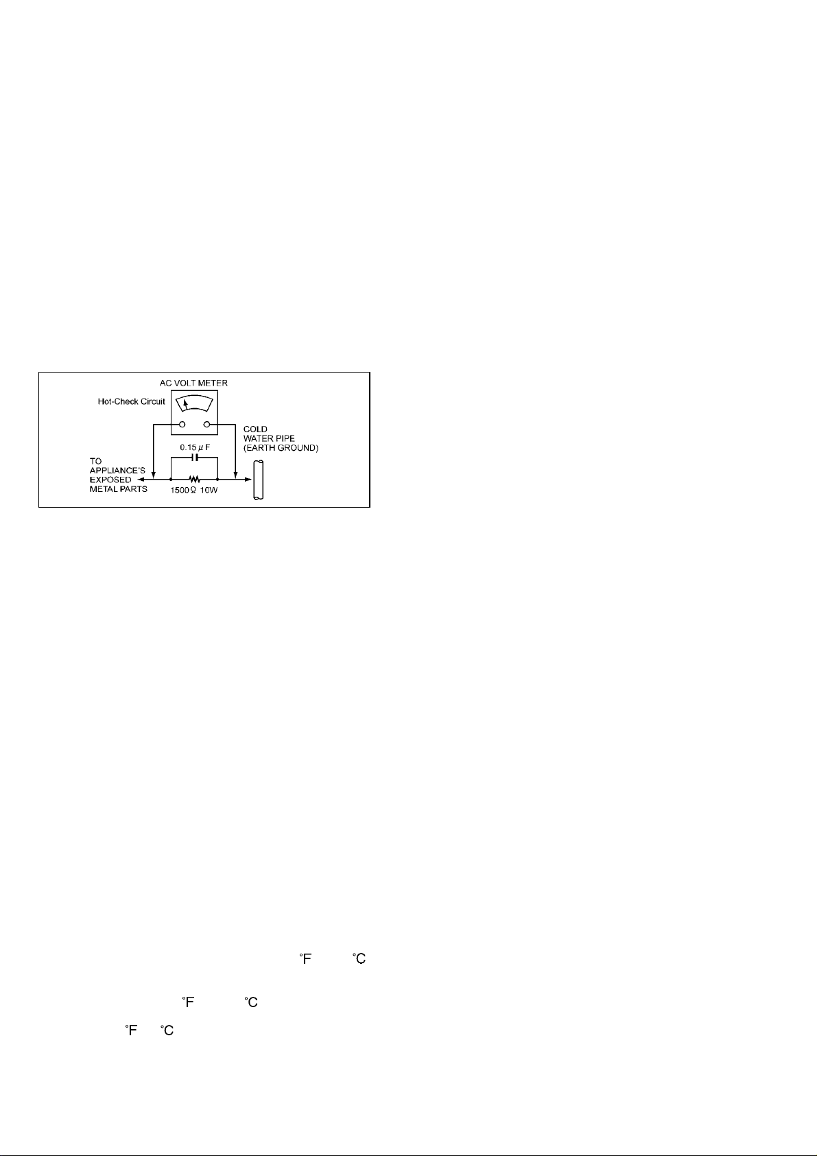
LEAKAGE CURRENT HOT CHECK (See Figure 1)
1. Plug the AC cord directly into the AC outlet.
Do not use an isolation transformer for this check.
2. Connect a 1.5KΩ, 10W resistor, in parallel with a 0.15µ F
capacitor, between each exposed metallic part on the set
an a good earth ground such as a water pipe, as shown
in Figure1.
3. Use an AC voltmeter, with 1000 ohms/volt or more
sensitivity, to measure the potential across the resistor.
4. Check each exposed metallic part, and measure the
voltage at each point.
5. Reverse the AC plug in the AC outlet repeat each of the
above measurements.
6. The potential at any point should not exceed 0.15 volts
RMS. A leakage current tester (Simpson Model 229
equivalent) may be used to make the hot checks,
leakage current must not exceed 0.1 milliamp. In case a
measurement is outside of the limits specified, there is a
possibility of a shock hazard, and the equipment should
be repaired and rechecked before it is returned to the
customer.
ABOU T LEAD FREE SOLDER (PbF)
Distinction of Pbf PCB:
PCBs (manufactured) using lead free solder will have a PbF
stamp on the PCB.
Caution:
1. Pb free solder has a higher melting point than standard
solder; Typically the melting point is 50–70
higher. Please use a high temperature soldering iron. In
case of the soldering iron with temperature control,
please set it to 700±20 (370±10 ).
2. Pb free solder will tend to splash when heated too high
(about 1100
/600 ).
(30-40 )
ELECTROSTATICALLY SENSITIVE (ES) DEVICES
Some semiconductor (solid state) devices can be damaged
easily by static electricity. Such components commonly are
called Electrostatically sensitive (ED) Devices. Examples of
typical ES devices are integrated circuits and some
field-effect transistors and semiconductor “chip” components.
The following techniques should be used to help reduce the
incidence of component damage caused by static electricity.
1. Immediately before handling any semiconductor
component or semiconductor-equipped assembly, drain
off any electrostatic charge on your body by touching a
known earth ground.
Alternatively, obtain and wear a commercially available
discharging wrist trap device, which should be removed
for potent i al sh oc k re as o ns prio r t o app l yi ng powe r t o th e
unit under test.
2. After removing an e lectrical assembly eq uipped with E S
devices, place the assembly on a conductive surface
such as aluminum foil, to prevent electrostatic charge
buildup or exposure of the assembly.
3. Use only a grounded tip soldering iron to solder or
unsolder ES devices.
4. Use only an anti-static solder removal device classified
as “anti-static” can generate electrical charges sufficient
to damage ES devices.
5. Do not use freon-propelled chemicals. These can
generate electrical charges sufficient to damage ES
devices.
6. Do not remove a replacement ES device from its
protective package until immediately before you are
ready to install it.
(most replacement ES devices are package with leads
electrically shorted together by conductive foam,
aluminum foil or comparable conductiv e material).
7. Immediately before removing the protective material
from the leads of a replacement ES device, touch the
protective material to the chassis or circuit assembly into
which the device will be installed.
CAUTION: Be sure no power is applied to the chassis or
circuit, and observe all other safety precautions.
8. Minimize bodily motions when handling unpackaged
replacement ES devices. (Otherwise hamless motion
such as the brushing together of your clothes fabric or
the lifting of your foot from a carpeted floor can generate
static electricity sufficient to damage an ES device).
X-RADIATION
WARNING
1. The potential source of X-radiation in EVF sets is the
High Voltag e sect ion and the p ictur e tube.
2. When using a picture tube test jig for service, ensure
that jig is capable of handling 10kV without causing
X-Radiation.
Note: It is important to use an accurate periodically
calibrated high voltage meter.
3. Measure the High Voltage. The meter (electric type)
reading should indicate 2.5kV, ±0.15kV. If the meter
indication is out of tolerance, immediate service and
correction is required to prevent the possibility of
premature component failure. To prevent an X-Radiation
possibility, it is essential to use the specified picture
tube.
- 6 -
AG-DVX100BP
- 7 -

AG-DVX100BE
- 8 -
- 9 -

- 10 -

MHNK150/0123457F6S8P

MODEL:
SERVICE INFORMATION
AG-DVX100BP/E/AN,102BEN,DVC180BMC
CONTENTS
1. SERVICING FIXTURES AND TOOLS ........................................................................................INF-1
1-1. Summary Table of Servicing Fixtures and Tools ................................................................INF-1
2. MAINTENANCE ..........................................................................................................................INF-4
2-1. Maintenance Schedule........................................................................................................INF-4
2-2. Cleaning of Tape Transport Part .........................................................................................INF-4
3. MANUAL TAPE EJECT (EMERGENCY EJECT) .......................................................................INF-5
4. LITHIUM BATTERY ....................................................................................................................INF-6
4-1. Replacement Procedure .....................................................................................................INF-6
5. SERVICE MENU .........................................................................................................................INF-7
5-1. SERVICE MENU (CAMERA mode)....................................................................................INF-8
5-1-1. Audio Filter ...............................................................................................................INF-8
5-1-2. Software Version Display.........................................................................................INF-9
5-1-3. Hour Meter Display ..................................................................................................INF-9
5-1-4. Adjustment item for Video Level ..............................................................................INF-10
5-1-5. DIF Status Display ...................................................................................................INF-10
5-1-6. LCD/EVF Correction ................................................................................................INF-11
5-2. DIAGNOSTIC MENU (VCR mode) .....................................................................................INF-12
5-2-1. How to display the Error Rate ..................................................................................INF-12
5-2-2. Other item ................................................................................................................INF-13
5-3. ADJUST MENU (VCR mode) .............................................................................................INF-13
5-3-1. Setting item for LISTA Adjustment ...........................................................................INF-14
6. EEPROM .....................................................................................................................................INF-15
6-1. Each Menu Data .................................................................................................................INF-15
6-1-1. Setting menu data ....................................................................................................INF-15
6-1-2. Service menu data ...................................................................................................INF-15
6-1-3. DIAGNOSTIC menu data.........................................................................................INF-16
6-1-4. ADJUST menu data .................................................................................................INF-16
6-1-5. The other data..........................................................................................................INF-16
7. CAMERA REMOTE.....................................................................................................................INF-17
7-1. ZOOM S/S REMOTE ..........................................................................................................INF-17
7-1-1. Record start / stop input...........................................................................................INF-17
7-1-2. Zooming control input ..............................................................................................INF-17
7-2. FOCUS/IRIS REMOTE .......................................................................................................INF-18
7-2-1. Focus control input...................................................................................................INF-18
7-2-2. IRIS control input .....................................................................................................INF-19
8. CAUTION WHEN INSTALLING AUDIO CONTROL KNOB .......................................................INF-20
9. INTERCONNECTION .................................................................................................................INF-21
10. CIRCUIT BOARD LAYOUT ........................................................................................................INF-22

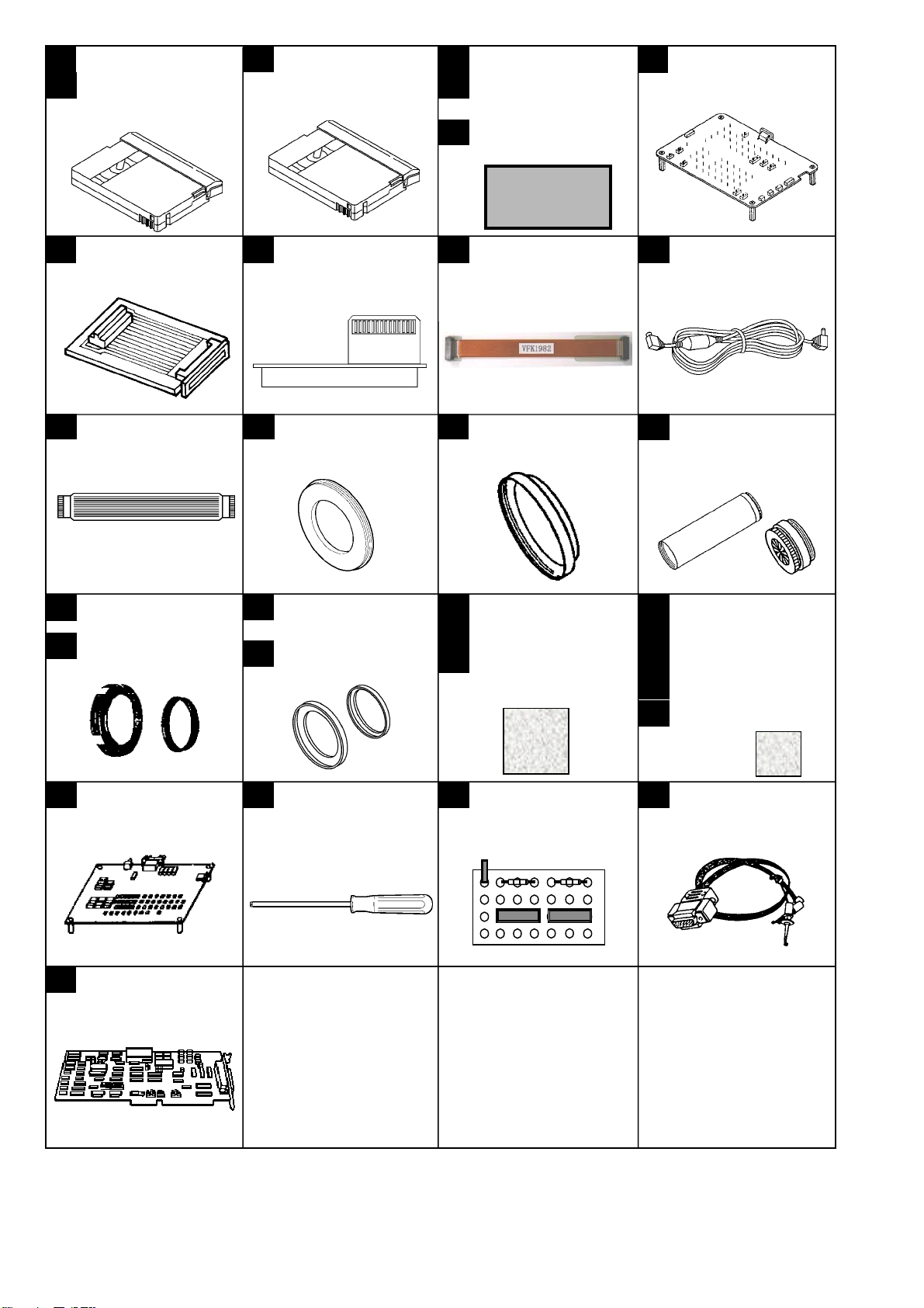
1. SERVICING FIXTURES AND TOOLS
The following servicing tools are required for mechanical and electrical servicing and alignment.
The items marked “NEW” in the following list are necessary for the AG-DVX100B/102B/DVC180B.
Please refer to “Y” and “N” in column of table below, which tools required for servicing the NTSC and PAL model.
Please refer to “Y” in column of table below, these tools were also use for servicing the AG-DVX100A/DVC180A.
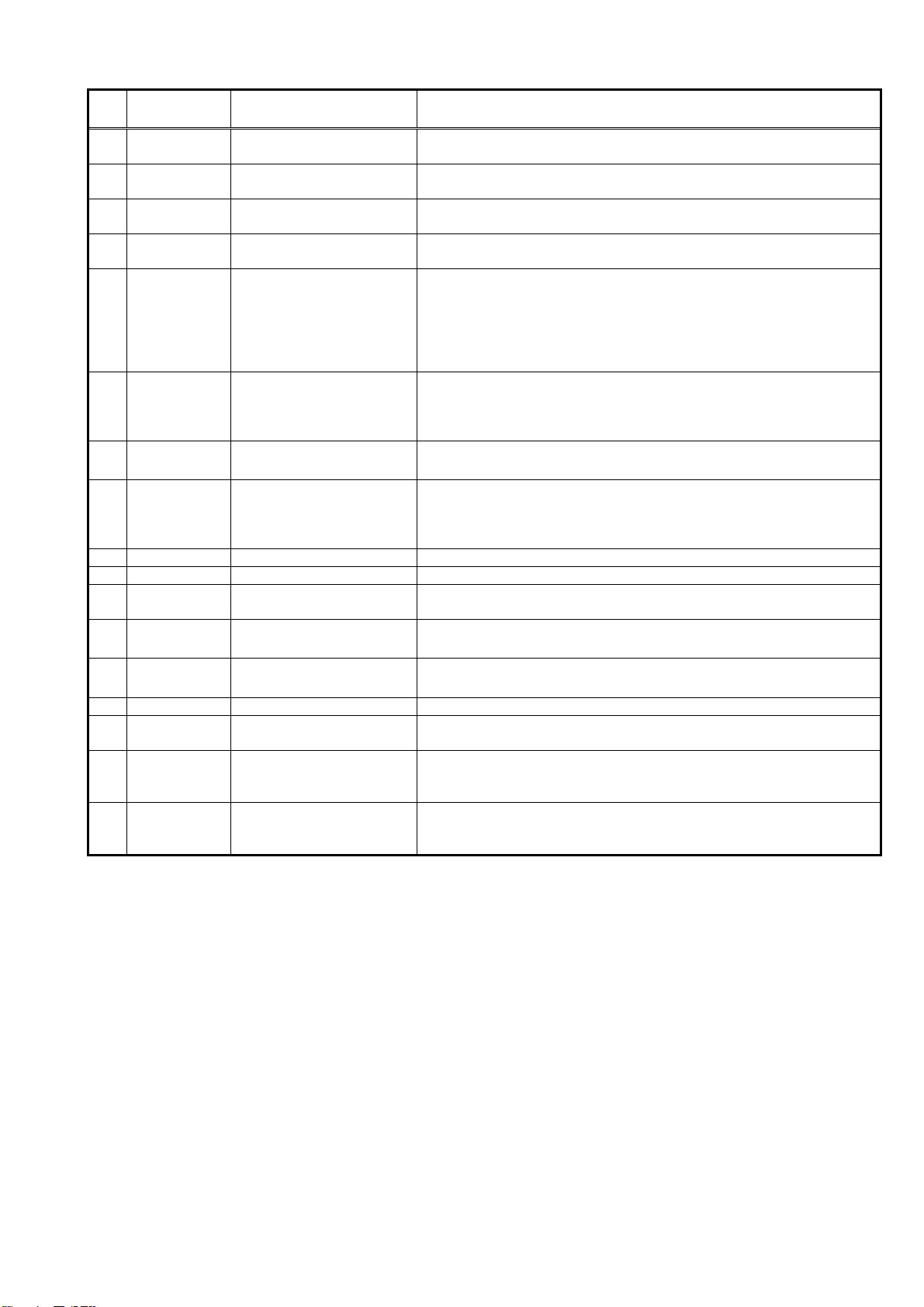
1-1. Summary Table of Servicing Fixtures and Tools
No
1 VFM3010EDS DV Alignment Tape (Color bar) Y N Y
2 VFM3110EDS DV Alignment Tape (Color bar) N Y Y
3 VFM3000LS DV Alignment Tape (Linearity) Y Y Y
4 *VVS0026 EVR Adjustment Software Y N N NEW
5 *VVS0027 EVR Adjustment Software N Y N NEW
6 *VFK1481N LISTA Software Y Y Y Download from the WEB site.
7 VFK1308P Measuring Board Y Y Y
8 VFK1309A EVR Connector Board Y Y Y Enable to use with VFK1309
9 VFK1763 Connector Adapter Y Y N 60-30pin.
10 VFK1982 Extension Cable Y Y N NEW
11 VJA0941 DC Cable Y Y Y 2 pieces Required
12 VFK1317 30pin Flat Cable Y Y Y 2 pieces Required
13 VFK1809 72mm Attachment Ring Y Y Y
14 VFK1164TAR43 43mm Attachment Ring Y Y Y
15 VFK1164TCM01 Collimator Set (Infinity Lens) Y Y Y
16 VFK1345 CC Filter Holder Y Y Y
17 VFK1346 Step Down Ring Y Y Y
18 VFK1659 Step-Up Ring (43mm-49mm) Y Y Y
19 VFK1660 Step-Up Ring (49mm-62mm) Y Y Y
20 VFK1341 CC Filter (LB40) Y N Y
21 VFK1342 CC Filter (LB80) N Y Y
22 VFK1347 CC Filter (LB120) Y Y Y
23 VFK1884 CC Filter (LBA2) Y Y Y
24 VFK1888 CC Filter (LBB6) Y Y Y
25 VFK1885 CC Filter (LBB2) Y N Y
26 VFK1886 CC Filter (CC C10) N Y Y
27 VFK1887 CC Filter (CC C20) N Y Y
28 VFK1409A Measuring Board Y Y Y NOTE 1
29 VFK1899 Post Driver Y Y N NOTE 2
30 VFK1810 LISTA Measuring Board Y Y Y NOTE 1
31 VFK1186 LISTA Cable Y Y Y
32 VFK1300 A/D Converter Board Y Y Y ISA PC Board.
Parts No. NAME
NTSC
Model
PAL
Model
AG-DVX100A/
DVC180A
REMARK
Download from the WEB site.
Download from the WEB site.
It uses with AG-DVC30/32/33
and AG-DVC60/62/63.
It uses with AG-DVC30/32/33
and AG-DVC60/62/63.
NOTE:
1. If you already have VFK1409S, it can be used for LISTA adjustment with VFK1810 instead of VFK1409A.
(Refer to item “1-5. Connection of LISTA Adjustment system” on page MECH-4 in section 3.)
2. This Post Driver use for servicing the “A” mechanism of consumer model.
INF-1
V
V
V
V
V
V
V
V
V
V
V
V
V
V
V
VFM3010EDS
1
VFM3110EDS
2
DV Alignment Tape
(Color bar)
FM3000EDS
3 4
DV Alignment Tape
(Linearity)
5
6
VS0026
VS0027
EVR Adjustment Software
VFK1481N
LISTA Software
DOWN LOAD
FK1309A
8 9 10 11
EVR Connector Board
VFK1763
Connector Adapter
VFK1982
Extension Cable
12 13 14
FK1317
30pin Flat Cable
FK1809
72 mm Attachment Ring
FK1164TAR43
43 mm Attachment Ring
(In case of using VFK1308P,
required 2pcs. of this cable)
VFK1345
16
CC Filter Holder
VFK1346
17
Step Down Ring
VFK1659
18
Step-up Ring (43mm - 49mm)
VFK1660
19
Step-up Ring (49mm - 62mm)
VFK1341 (LB40)
20
VFK1342 (LB80)
21
VFK1347 (LB120)
22
CC Filter
VFK1345
28 29 30
FK1409A
Measuring Board
VFK1346
VFK1660
FK1899
Post Driver
VFK1659
FK1810
LISTA Measuring Board
32
FK1300
A/D Converter Board
FK1308P
7
Measuring Board
JA0941
DC Cable
15
FK1164TCM01
Collimator Set
(Infinity Lens)
VFK1884 (LBA2)
23
VFK1888 (LBB6)
24
VFK1885 (LBB2)
25
VFK1886 (CC C10)
26
VFK1887 (CC C20)
27
CC Filter
FK1186
31
LISTA Cable
INF-2
To determine which servicing fixtures and tools are required for each adjustment, refer to the following table.
No. Parts No. NAME
1 2 VFM3010EDS
VFM3110EDS
3 VFM3000LS DV Alignment Tape (Linearity) 1-8. LISTA Sensitivity Detection (SEC.3)
4 5 VVS0026
VVS0027
6 VFK1481N LISTA Software 1-8. LISTA Sensitivity Detection (SEC.3)
VFK1308P
7
VFK1309A
8
VFK1763
9
VFK1982
10
VJA0941
11
VFK1317
12
13 VFK1809 72mm Attachment Ring 4-5. Zoom tracking adjustment (SEC.4)
14
VFK1164TAR43
15
VFK1164TCM01
16
VFK1345
17
VFK1346
18
VFK1659
19
VFK1660
20 VFK1341 CC Filter (LB40) 4-6-4. White balance adjustment (3600K) (SEC.4)
21 VFK1342 CC Filter (LB80) 4-6-3. White balance adjustment (4500K) (SEC.4)
22 VFK1347 CC Filter (LB120) 4-6-2. White balance adjustment (5100K) (SEC.4)
23
VFK1884
24
VFK1888
25
VFK1885
26
VFK1886
27 VFK1887 CC Filter (CC C20) 4-6-3. White balance adjustment (4500K) (SEC.4)
28 VFK1409A Measuring Board 1-8. LISTA Sensitivity Detection (SEC.3)
29 VFK1899 Post Driver 1-9. LISTA Linearity Adjustment (SEC.3)
30
VFK1810
31
VFK1186
32
VFK1300
DV Alignment Tape (Color bar)
DV Alignment Tape (Color bar)
EVR Adjustment Software 4. ADJUSTMENT PROCEDURE (CAMERA SECTION) (SEC.4)
Measuring Board
EVR Connector Board
Connection Adapter
Extension Cable
DC Cable
30pin Flat Cable
43mm Attachment Ring
Collimator Set (Infinity Lens)
CC Filter Holder
Step Down Ring
Step-Up Ring (43mm-49mm)
Step-Up Ring (49mm-62mm)
CC Filter (LBA2)
CC Filter (LBB6)
CC Filter (LBB2)
CC Filter (CC C10)
LISTA Measuring Board
LISTA Cable
A/D Converter Board
5-2. PG shifter adjustment (SEC.4)
1-9. LISTA Linearity Adjustment (SEC.3)
5. ADJUSTMENT PROCEDURE (VTR SECTION) (SEC.4)
1-9. LISTA Linearity Adjustment (SEC.3)
1-8. LISTA Sensitivity Detection (SEC.3)
1-9. LISTA Linearity Adjustment (SEC.3)
1-11. Self-REC/PLAY Envelope Waveform Confirmation (SEC.3)
4. ADJUSTMENT PROCEDURE (CAMERA SECTION) (SEC.4)
5. ADJUSTMENT PROCEDURE (VTR SECTION) (SEC.4)
4-6-2. White balance adjustment (5100K) (SEC.4)
4-6-3. White balance adjustment (4500K) (SEC.4)
4-6-4. White balance adjustment (3600K) (SEC.4)
4-5. Zoom tracking adjustment (SEC.4)
4-6-2. White balance adjustment (5100K) (SEC.4)
4-6-3. White balance adjustment (4500K) (SEC.4)
4-6-4. White balance adjustment (3600K) (SEC.4)
4-6-3. White balance adjustment (4500K) (SEC.4)
4-6-2. White balance adjustment (5100K) (SEC.4)
4-6-4. White balance adjustment (3600K) (SEC.4)
1-9. LISTA Linearity Adjustment (SEC.3)
1-10. Tape Path Confirmation (SEC.3)
1-11. Self-REC/PLAY Envelope Waveform Confirmation (SEC.3)
1-8. LISTA Sensitivity Detection (SEC.3)
1-9. LISTA Linearity Adjustment (SEC.3)
ADJUSTMENT ITEM
INF-3
2. MAINTENANCE
r
Maintenance is done by periodically performing suitable maintenance servicing in order to maintain the best
condition, so that the user can use the equipment safely. Video equipment with mounted mechanisms have parts
which will wear, and their wear and deterioration cause troubles. Dust and dirt also can impair stable operation. For
this reason it is important not to just perform repair at the time of trouble, but also to perform suitable maintenance
at regular intervals.
The maintenance schedule requires replacement of mechanism unit, which contains a cylinder unit and so on.
2-1. Maintenance Schedule
No. Part Name Part No. Cleaning Replacement Remark
--- Tape Transport Part ------ 100 hours ------ *1
1 Mechanism Chassis Unit VXY1903Z1 ------ Every 2000 hours *2
2 Zoom Motor Unit L6DABBHC0001 ------ Every 4000 hours *2
Note:
Hours of use are based on the head rotation hours. (Head rotation hours can be confirm on item HOUR METER in
OTHER FUNCTION menu.)
Hours of use are recommendation. It may depend on temperature, humidity, quality of tape or dust condition.
Hours of use are listed as the reference of maintenance. They do not mean guarantee hours.
*1. Tape Transport part is cleaned by cleaning liquid.
*2. Please refer to the most recent execution outline, as the maintenance specifications and the part numbers may
change.
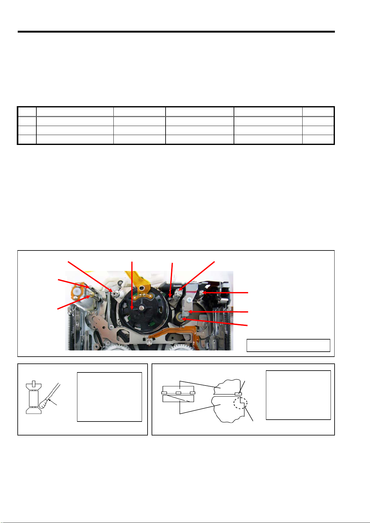
2-2. Cleaning of Tape Transport Part
Please clean the below indicated tape transport p arts with cleaning liquid when needed.
(Tension Post, S1 Post, Cylinder & Heads, T1 Post, T2 Post, T3 Post, Capst an Shaft and Pinch Roller)
Tension Post
S2 Post
S1 Post
Thin
stick
When cleaning the
post, wrap a cloth on a
pick. Wipe each post
with a cloth dipped in
cleaning liquid. And
wipe it again with dry
cloth.
Cylinder
Upper Cylinder
Lower Cylinder
T2 Post T1 Post
T3 Post
Capstan Shaft
Pinch Roller
LOADING condition
Head
Lead
Do not forget cleaning
the upper Cylinder,
Head, tape transport
part of Lower Cylinde
and Lead, when
cleaning the Cylinder.
INF-4
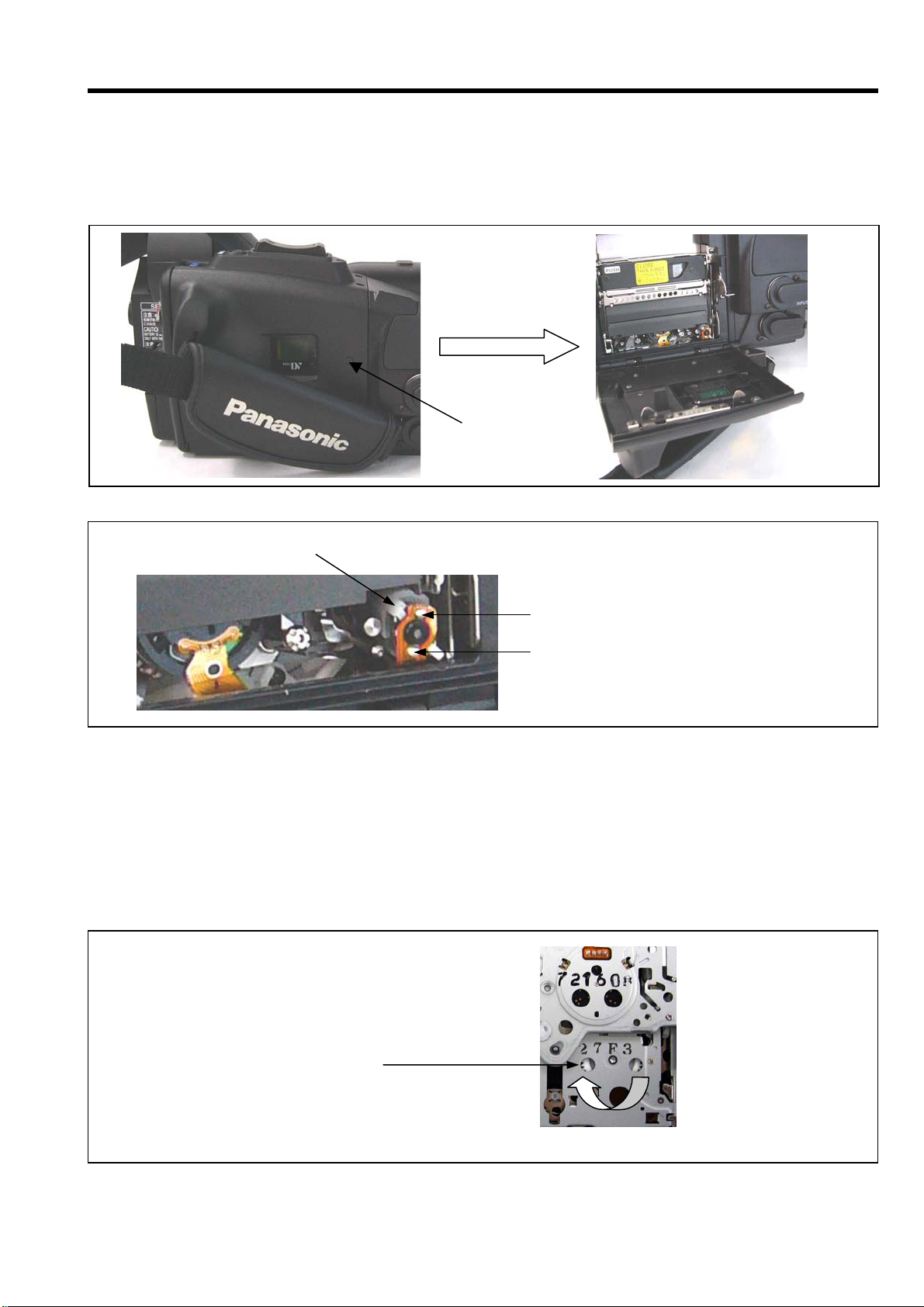
3. MANUAL TAPE EJECT (EMERGENCY EJECT)
When the tape cannot be ejected by norm al operation because of trouble in the elec trical system or mechanical
system, the tape can be removed from the unit manually by using the following method.
NOTE: By below indicated m ethod, the unit will not tak e up tape slack. Be careful when r emoving the tape f rom
Cassette Holder.
1. Unscrew the screw (A) and open the cassette cover as shown in figure.
2. Supply 4.5 Volts using 3 AA batteries in series to unload the posts using the motor.
3. Stop supplying the power when the tape is ejected and remove the tape from Cassette Holder.
<How to rolls up tape>
Be sure to take up the tape slack so that tape does not become damaged.
1. Remove the Mechanism Unit.
2. Supply 4.5 Volts to unload the posts using the motor.
3. Stop supplying the power at unloading complete position.
NOTE: If power is supplied too long, then the Cassette tape will be ejected prematurely.
4. Turn the Gear of Supply Reel as shown in figure, and this will take up the slack in the tape.
5. Supply 4.5 Volts again to eject the tape using the motor and remove the tape from Cassette Holder.
LOADING MOTOR
Turn this Gear with the tip of
a tweezers.
SCREW (A)
UNLOADING ............A: +4.5 V B: GND
LOADING ................. A: GND B: +4.5V
(B)
(A)
(Bottom side of Mechanism)
INF-5

4. LITHIUM BATTERY
4-1. Replacement Procedure
1. There is a Lithium battery on the BACK CONNECT C.B.A.
2. Unsolder the Lithium battery a nd then r eplace with the new one. Please refer to item “16. Remov al of BACK
CONNECT C.B.A.” in section 2(Disassembly Procedure) about how removal of BACK CONNECT C.B.A..
NOTE:
The lithium battery is a critical component.
It must never be subjected to excessive heat of discharge.
It must therefore only be fitted in equipment designed specifically for its use.
Replacement batteries must be of the same type and manufacture.
They must be fitted in the same manner and location as the original battery, with the correct polarity contacts
observed.
Do not attempt to re-charge the old battery or re-use it for any other purpose.
It should be disposed of in waste products destined for burial rather than incineration.
VTR C.B.A.
(LI-BATT)
IC2002<3>
(REAL TIME CLOCK)
P2002 P53
11
RTC_3V 60B 60A
B51
BACK_CONNECT C.B.A.
BACK CONNECT C.B.A.
LITHIUM BATTERY
CAUTION
Danger of explosion if battery is incorrectly replaced.
Replace only with the same or equivalent type recommended by the equipment manufacturer.
Discard used batteries according to manufacture’s instructions.
INF-6

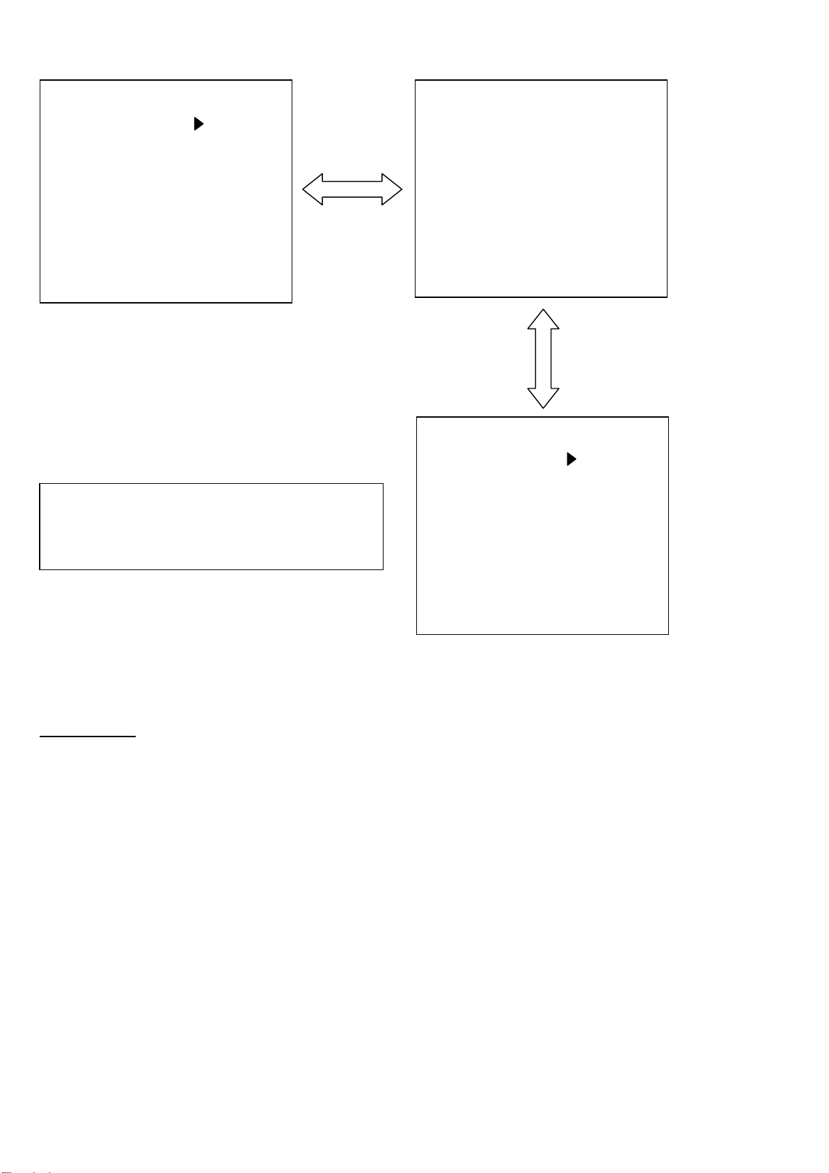
5. SERVICE MENU
The SERVICE(CAMERA mode), DIAGNOSTIC(VCR mode) and ADJUST(VCR mode) menu can be displayed as
follows.
Press the button in order of “ADUB button” → “STOP button” → “MODE CHK button” → “MENU button”,
SERVICE menu in CAMERA mode, DIAGNOSTIC and the ADJUST menu in VCR mode can be displayed in
addition to a setup menus.
■
Next, Tilt the OPERATION lever in the UP( ► :PLAY) or DOWN (
ADJUST menu, press SET(STILL) of the OPERATION lever to open the DIAGNOSTIC or ADJUST menu.
Normal Screen
(CAMERA mode)
Press the button in order of “ADUB
button” → “STOP button” → “MODE
CHK button” → “MENU button”.
1. SCENE FILE
2. CAMERA SETUP
3. SW MODE
4. AUTO SW
5. RECORDING SETUP
6. DISPLAY SETUP
7. OTHER FUNCTIONS
SERVICE MENU
CAMERA MENU
PUSH MENU TO EXIT
1. PLAYBACK FUNCTIONS
2. RECORDING SETUP
3. AV IN/OUT SETUP
4. DISPLAY SETUP
5. OTHER FUNCTIONS
DIAGNOSTIC MENU
ADJUST MENU
:STOP) direction, select the DIAGNOSTIC or
Normal Screen
(VCR mode)
VCR FUNCTIONS
PUSH MENU TO EXIT
INF-7
5-1. SERVICE MENU (CAMERA mode)
DEFFECT COMP OFF
AUDIO FILTER ON
VTR SUB MICON 1.001
VTR MAIN MICON 1.77-P-F
VTR EEPRPM 0.007
VTR EEPROM SUM D7EF
CAM MICON 0.D0
CAM EEPROM 0.CA
SERVICE MENU
CYLINDER 10000H
TAPE RUN 10000H
THREADING 10000T
Y LEVEL 1B
C LEVEL 27
DIF INFO OFF
DEBUG DISP OFF
DEBUG MODE OFF
PUSH MENU TO RETURN
NOTE: Please do not change the setting of the
items of “DEFFECT COMP”, “DEBUG
DISP” and “DEBUG M ODE”. These items
are for factory use only.
Factory default setting is “OFF”.
LCD OFFSET OFF
EVF OFFSET OFF
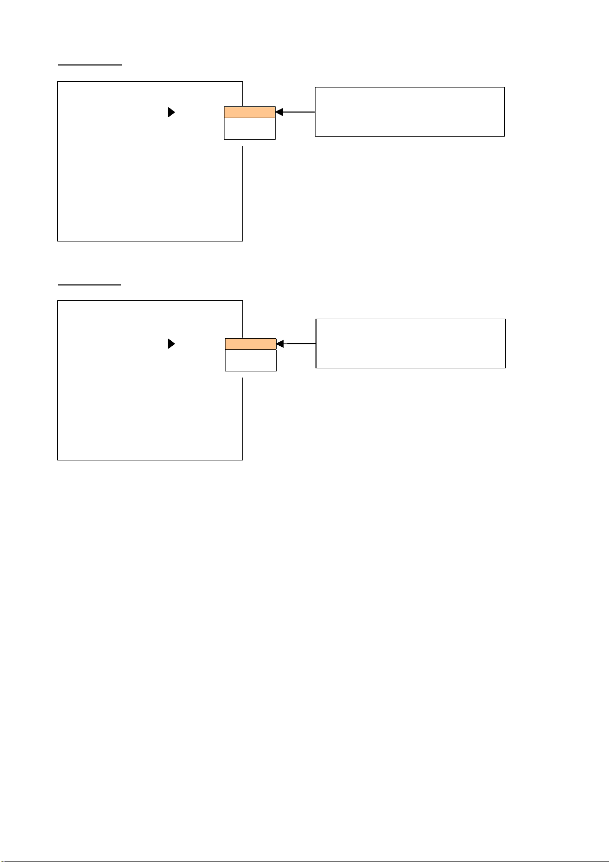
5-1-1. Audio Filter
AUDIO F ILTER
ON: The mechanism noise cancellation function operates by IC3001(DUO).
OFF: The mechanism noise cancellation function does not operates by IC3001(DUO).
Factory default setting is “ON”.
SERVICE MENU
PUSH MENU TO RETURN
SERVICE MENU
PUSH MENU TO RETURN
INF-8

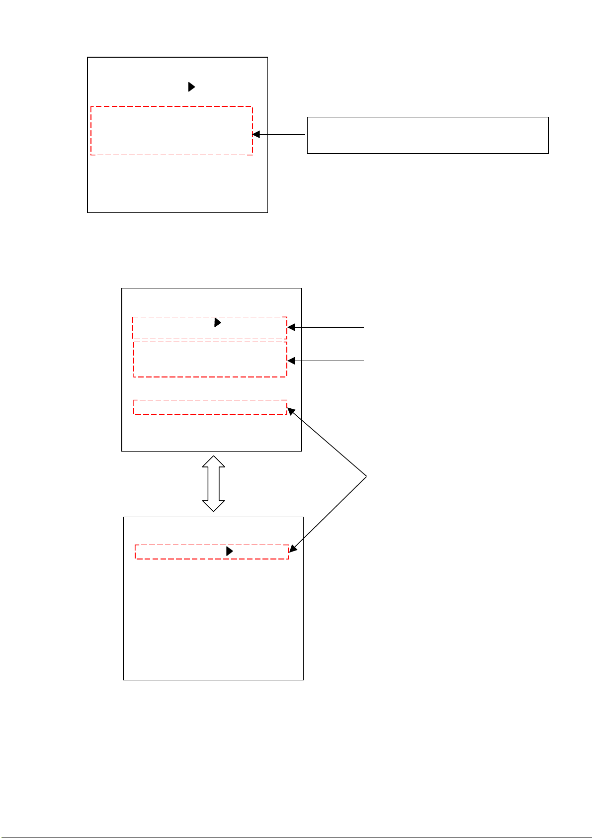
5-1-2. Software Version Display.
This unit have three pieces of microprocessor and two pieces of EEPROM.
--- CAMERA board VTR board
Microprocessor IC301 IC2001(VTR MAIN MICON) IC3001(VTR SUB MICON)
EEPROM IC307 IC2006 ---
VTR C.B.A.(Foil side)
CAMERA C.B.A.(Foil side)
IC3001
IC2001
IC2006
IC301
IC307
This indicates the
value of the chec k sum
value of the VTR
EEPROM displayed in
hexadecimal.
DEFFECT COMP OFF
AUDIO FILTER ON
VTR SUB MICON 1.001
VTR MAIN MICON 1.77-P-F
VTR EEPRPM 0.007
VTR EEPROM SUM D7EF
CAM MICON 0.D0
CAM EEPROM 0.CA
SERVICE MENU
PUSH MENU TO RETURN
The version of VTR, and the
CAMERA microprocessor,
VTR and CAMERA EEPROM
are displayed.
(In case of VTR MAIN MICON)
- P - F
*.**
Version Number
F = FLASH
M = MASK
N = NTSC
P = PAL
5-1-3. Hour Meter Display.
CYLINDER 10000H
TAPE RUN 10000H
THREADING 10000T
Y LEVEL 1B
C LEVEL 27
DIF INFO OFF
DEBUG DISP OFF
DEBUG MODE OFF
ITEM Display Data Description
TAPE RUN 00000H – 99999H It displays the time that the tape is running in units of hours.
THREADING 00000T – 99999T It displays the number of times the tape is inserted.
CYLINDER 00000H – 99999H
SERVICE MENU
TAPE RUN, THREADING are
displayed in addition to the rotating
time of the Cylinder (CYLINDER).
PUSH MENU TO RETURN
It displays the t ime that the c ylinder is r otating in units of hours.
It displays same tim e as in the item HOUR METER of OT HER
FUNCTION menu.
INF-9

5-1-4. Adjustment item for Video Level
Y LEVEL
Y level of VIDEO OUT and S-VIDEO OUTPUT signal can be adjusted on this item.
The displayed value is the same as value for Luminance level adjustment in EVR adjustment.
C LEVEL
C level of VIDEO OUT and S-VIDEO OUTPUT signal can be adjusted on this item.
The displayed value is the same as value for Chroma level adjustment in EVR adjustment.
5-1-5. DIF Status Display.
CYLINDER 10000H
TAPE RUN 10000H
THREADING 10000T
Y LEVEL 1B
C LEVEL 27
DIF INFO OFF
DEBUG DISP OFF
DEBUG MODE OFF
NORMAL: The DIF STATUS display is updated every five frames.
FAST: The DIF STATUS display is updated every frame.
Factory default setting is “OFF”.
Items Description Remark
NODECNT Number of NODE connections.
MY_ID NODE ID of this unit.
ROOT_ID ROOT ID
IRM_ID PHY ID of IRM IRM(Isochronous Resonance Manager)
IN_CH Input channel number of Isochronous data.
OUT_CH Output channel number of Isochronous data.
DIFMODE DIF mode
RX_IN Received condition of Isochronous data.
O_BCC Transmitted condition of Isochronous data.
STYPE Type of VIDEO signal
FIELD NTSC/PAL
SPEED Speed of Isochronous data. IN_SPD in VCR MODE
UID USER ID of 1394 equipment
AS Source pack of AUDIO
ASC Source control pack of AUDIO
VS Source pack of VIDEO
VSC Source control pack of VIDEO
HEADER HEADER pack
SERVICE MENU
PUSH MENU TO RETURN
OFF
NORMAL
FAST
Set the item “DIF INFO” to NORMAL
or FAST and it does ON/OFF of the
DIF STATUS display b y pressing the
MODE CHECK button on normal
screen.
INF-10
5-1-6. LCD/EVF Correction
LCD OFFSET
LCD OFFSET OFF
EVF OFFSET OFF
EVF OFFSET
LCD OFFSET OFF
EVF OFFSET OFF
SERVICE MENU
PUSH MENU TO RETURN
SERVICE MENU
PUSH MENU TO RETURN
R signal output to LCD is corrected.
OFF
1
2
1: Correction level 1
2: Correction level 2
R signal output to EVF is corrected.
OFF
1
2
1: Correction level 1
2: Correction level 2
INF-11

5-2. DIAGNOSTIC MENU (VCR mode)
y
f
A
5-2-1. How to display the Error Rate.
This unit can be displayed Error Rate and it shows the playing condition of the VCR.
In case of the error rate is displayed, BER DISPLAY and SAMPLE SPEED mode is select on DIAGNOSTIC menu.
BER DISPLAY OFF
SAMPLE SPEED SLOW
DIF INFO OFF
CYLINDER 10000H
TAPE RUN 10000H
THREADING 10000T
BER DISPLAY TOTAL
SAMPLE SPEED SLOW
DIF INFO OFF
CYLINDER 10000H
TAPE RUN 10000H
THREADING 10000T
When selecting TOTAL in BER DISPLAY
mode, it is displayed “TOT” and if select
VIDEO, it is displayed “VID” and if select
AUDIO, it is displayed “AUD”.
TOT
TOT
DIAGNOSTIC MENU
PUSH MENU TO EXIT
DIAGNOSTIC MENU
PUSH MENU TO EXIT
CH1
CH2
CH1
CH2
OFF
VIDEO
AUDIO
TOTAL
SLOW
FAST
Select the item BER DISPLAY and press
SET(STILL) of OPERATION LEVER.
Select VIDEO, AUDIO or TOTAL b
OPERATION LEVER and press SET(STILL) o
OPERATION LEVER.
Factory default setting is “OFF”.
fter selecting BER DISPLAY mode, move to
item of SAMPLE SPEED by tilt the
■
OPERATION LEVER in the DOWN (
direction.
Select SLOW or FAST by OPERATION LEVER
and press SET(STILL) of OPERATION LEVER.
Factory default setting is “SLOW”.
The Audio Level Meter is change to error rate
display, when returning to the normal screen.
NOTE:
The display screen is changed only in the VCR
mode.
The color of the bar
In case of green display: Error rate is good
In case of red display: Error rate is bad
:STOP)
How to confirm the Error rate.
1. Select the TOTAL in item of BER DISPLAY.
2. Record the color bar signal on LP mode and playback the recorded portion. Confirm that the number of bar on
display within 10 bars or less. The less bars displayed the better the error rate.
INF-12
5-2-2. Other item.
A
y
BER DISPLAY OFF
SAMPLE SPEED SLOW
DIF INFO OFF
CYLINDER 10000H
TAPE RUN 10000H
THREADING 10000T
DIAGNOSTIC MENU
These items are displayed even by the CAMER
SERVICE menu. (refer to item 5-1-3 and 5-1-5. )
PUSH MENU TO EXIT
5-3. ADJUST MENU (VCR mode)
ATF GAIN OFF
LINEARITY OFF
AUDIO FILTER ON
Y LEVEL 1B
C LEVEL 27
DEBUG DISP OFF
DEBUG MODE OFF
LCD OFFSET OFF
EVF OFFSET OFF
NOTE: Please do not change th e setting of t he items of “ DEBUG DISP” and “DEBUG MODE”. T hese items
are for factory use only.
ADJUST MENU
Setting item for LISTA Measurement
These items are d ispl ayed even by
the CAMERA SERVICE menu.
(refer to item 5-1-1 and 5-1-4. )
PUSH MENU TO EXIT
These items are d ispl ayed even b
the CAMERA SERVICE menu.
(refer to item 5-1-6. )
ADJUST MENU
PUSH MENU TO EXIT
INF-13

5-3-1. Setting item for LISTA Measurement
ATF GAIN
The speed of the tape changes if this item set to “ON” for the ATF sensitivity confirmation.
After selected “ON” , By pressing SET(STILL) of OPERATION LEVER, enter the adjustment mode an d t hen e x it th e
menu once. The VTR mode is operated when the menu mode is exited temporarily. The screen below is displayed.
NOW SERVO ADJUST
PUSH MENU TO RETURN
It will be returned to ADJUST MENU when the MENU button is pressed in this condition.
ATF GAIN OFF
LINEARITY OFF
AUDIO FILTER ON
Y LEVEL 1B
C LEVEL 27
DEBUG DISP OFF
DEBUG MODE OFF
LCD OFFSET OFF
LINEARITY
The ATF sensitivity changes if this item set to “ON” for the LINEARITY confirmation.
After selected “ON” , By pressing SET(STILL) of OPERATION LEVER, enter the adjustment mode an d t hen e x it th e
menu once. The VTR mode is operated when the menu mode is exited temporarily. The screen below is displayed.
PUSH MENU TO RETURN
It will be returned to ADJUST MENU when the MENU button is pressed in this condition.
ADJUST MENU
PUSH MENU TO EXIT
NOW SERVO ADJUST
After selected “ON”, By pressing SET(STILL) of OPERATION LEVER
OFF
ON
(Adjustment mode screen)
NOW SERVO ADJUST
PUSH MENU TO RETURN
Press MENU button.
INF-14

6. EEPROM
Several information are stored in EEPROM. Please refer to below explanation, which data stored in EEPROM.
6-1. Each Menu Data
6-1-1. Setting menu data
1. SCENE FILE
2. CAMERA SETUP
3. SW MODE
4. AUTO SW
5. RECORDING SETUP
6. DISPLAY SETUP
7. OTHER FUNCTIONS
CAMERA MENU
PUSH MENU TO EXIT
n : Each setting value are stored in VTR EEPROM.
▲ : Each setting value are stored in CAMERA EEPROM.
NOTE1: The item “PROGRESSIVE” and “NAME EDIT” in SCENE FILE screen, which is stored in VTR EEPROM.
NOTE2: The item “Aspect CONV” in CAMERA SETUP screen, which is stored in VTR EEPROM.
6-1-2. SERVICE menu data
Please refer to as follows.
ITEM STORED IN
DEFECT COMP X
AUDIO FILTER VTR EEPROM
VTR SUB MICON VTR SUB MICON (IC3001)
VTR MAIN MICON VTR MAIN MICON (IC2001)
VTR EEPROM VTR EEPROM
VTR EEPROM SUM VTR EEPROM
CAM MICON CAM MICON (IC301)
CAM EEPROM CAM EEPROM
CYLINDER VTR EEPROM
TAPE RUN VTR EEPROM
THREADING VTR EEPROM
Y LEVEL VTR EEPROM
C LEVEL VTR EEPROM
DIF INFO X
DEBUG DISP X
DEBUG MODE X
LCD OFFSET VTR EEPROM
EVF OFFSET VTR EEPROM
VCR FUNCTIONS
▲
▲
▲
▲
n
n
n
1. PLAYBACK FUNCTIONS
2. RECORDING SETUP
3. AV IN/OUT SETUP
4. DISPLAY SETUP
5. OTHER FUNCTIONS
PUSH MENU TO EXIT
n
n
n
n
n
Common display items
INF-15

6-1-3. DIAGNOSTIC menu data
Please refer to as follows.
ITEM STORED IN
BER DISPLAY X
SAMPLE SPEED X
DIF INFO X
CYLINDER VTR EEPROM
TAPE RUN VTR EEPROM
THREADING VTR EEPROM
6-1-4. ADJUST menu data
Please refer to as follows.
ITEM STORED IN
ATF GAIN X
LINEARITY X
AUDIO FILTER X
Y LEVEL VTR EEPROM
C LEVEL VTR EEPROM
DEBUG DISP X
DEBUG MODE X
LCD OFFSET VTR EEPROM
EVF OFFSET VTR EEPROM
6-1-5. The other data
Except setting menu data, below indicated information are stored in EEPROM.
EEPROM INFORMATION REMARK
CAMERA EEPROM
VTR EEPROM
CAMERA adjustment value Adjustment values are set by EVR software.
Control data ------------------
VTR adjustment Value
HOUR METER ------------------
Time code data -----------------Control data ------------------
Adjustment values are set by EVR software or
SERVCE/ADJUST menu.
INF-16

7. CAMERA REMOTE
The operation of zoom operation and record start/stop can be remotely controlled by connecting a remote controller
with ZOOM S/S remote jack.
The operation of focus and iris operation can be remotely controlled by connecting a remote controller with
FOCUS/IRIS remote jack.
NOTE: CAMERA remote control is only effective in the CAMERA mode.
7-1. ZOOM S/S REMOTE
Please refer to below indicated specification, When external remote is checked.
Terminal (refer to figure A) Contents
A Record start/stop input
B Zooming control input
C GND
7-1-1. Record start / stop input
Every time A terminal connects with the GND, it repeats recording and a recording stop.
7-1-2. Zooming control input
With the voltage to input to the B terminal, the zoom speed changes. As for the relation between the zoom control
voltage and the zoom speed, it is as shown in the following.
Relation between the zoom control voltage and zoom speed
Zoom speed (sec.)
Zoom control voltage (V)
Figure B
Equivalent circuit of ZOOM S/S REMOTE jack
Measuring point of zoom control voltage
Figure A
NOTE:
The control voltage and the
zoom speed, which are shown
below are a reference value.
Because there is a little
difference, see as t he reference
data.
INF-17

7-2. FOCUS/IRIS REMOTE
Please refer to below indicated specification, When external remote is checked.
Terminal (refer to figure A) Contents
A GND
B FOCUS control input
C IRIS control input
D IRIS(AUTO/MANU) switch input
Equivalent circuit of FOCUS/IRIS REMOTE jack
Figure C
7-2-1. Focus control input
With the voltage to input to the B terminal, the focus is changes. As for the relation between the focus control
voltage and the focus, it is as shown in the following.
Relation between the focus control voltage and focus
FOCUS
NEAR
When terminal B is open, the focus remote control becomes invalid.
0Ω 10kΩ 20kΩ
FAR
0 0.5
Focus control voltage (V)
1.0 1.5 2.0
NOTE:
The control voltage and the
focus, which are shown below
are a reference value . Because
there is a little difference, see
as the reference data.
Figure D
4-pole / 3.5mm diameter
INF-18
 Loading...