

Page 1
®
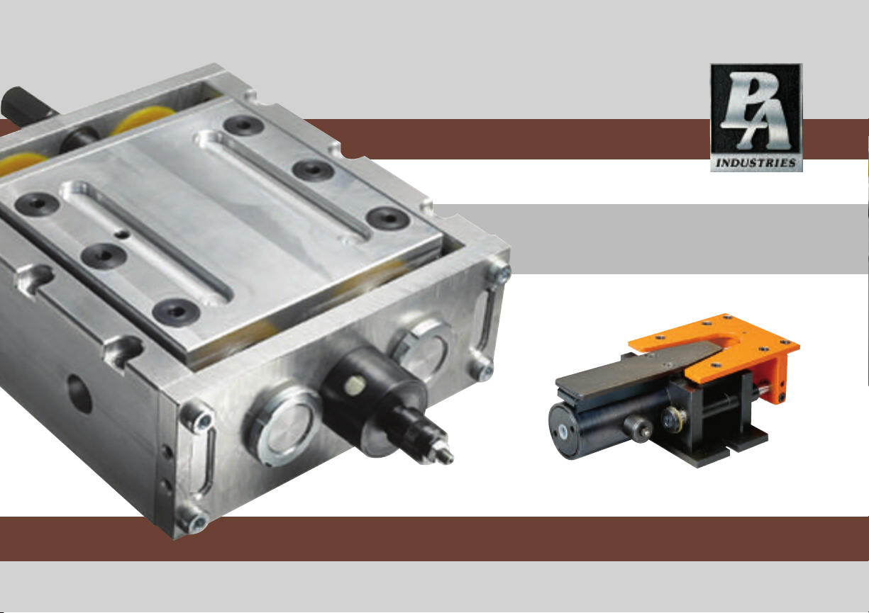
TRANSPORTER
Installation & Operating Instruction Manual
Page 2
P/A INDUSTRIES INC.
The Original Transporter.
The Transporter is a totally unique material handling device.
Protected under USA and foreign patents, these low profile,
beltless conveyors are pneumatically powered and have
become a cost effective alternative to conventional conveyors.
There are no belts or bearings to wear out or maintain.
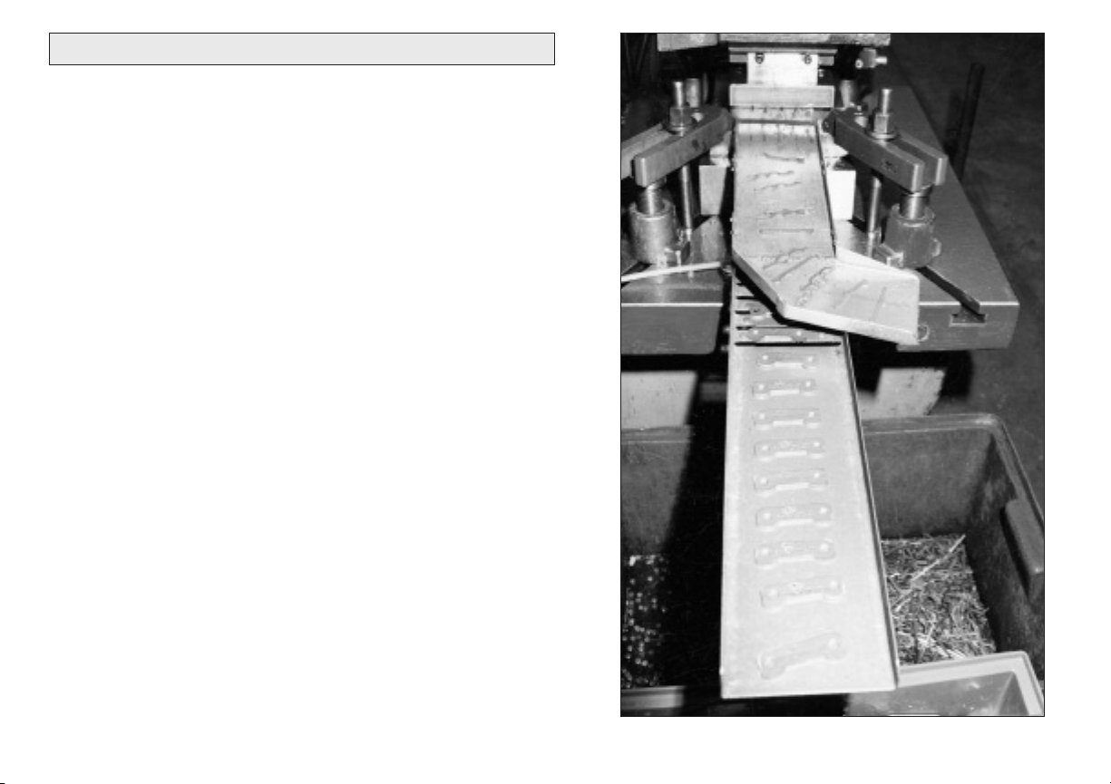
The rhythmic vibrating or shaking motion moves parts or
scrap along a custom tray or chute designed to fit your tool or
application. Trays can be fabricated out of various materials
to suit any size opening and transport the pieces into the
parts bin or scrap container.
Contact our Sales Application Engineering Department for a
free video showing several different ways customers have
used the Transporter.
APPLICATIONS .................................................................... 3
INSTALLATION .................................................................... 4
MODEL TP-3 SERVICE ....................................................... 6
MODEL TP-10 SERVICE ................................................... 10
MODEL TP-40 SERVICE ................................................... 14
MODEL TP-70 SERVICE .................................................... 18
MODEL TP-140 SERVICE ................................................. 22
TECHNICAL DATA .............................................................. 26
RECOMMENDED TRAY SUPPORTS ................................ 27
2
Page 3
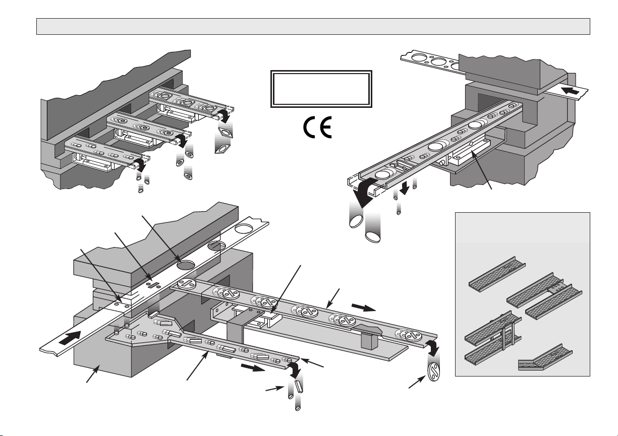
APPLICATIONS
Third Stage Blank
Second Stage Punch
First Stage
Pierce
U.S. PATENT NO.
4,444,346
Model TP-10
Transporter
Upper Tray for
Parts Removal
Model TP-10
Design the tray
configuration
to suit your application
Feed
Direction
Progressive Die
Lower Tray
Scrap
Slugs
Lower Tray for
Scrap Removal
Stamped Part
3
Page 4
INSTALLATION
60
(4)
75
(5)
1. Rigidly Mount the Transporter to a solid surface using
these recommended bolts sizes:
Model Quantity Metric Inch
TP-3 4 M 8 5/16
TP-10 4 M 8 5/16
TP-40 2 M10 3/8
TP-70 6 M 8 5/16
TP-140 6 M 8 5/16
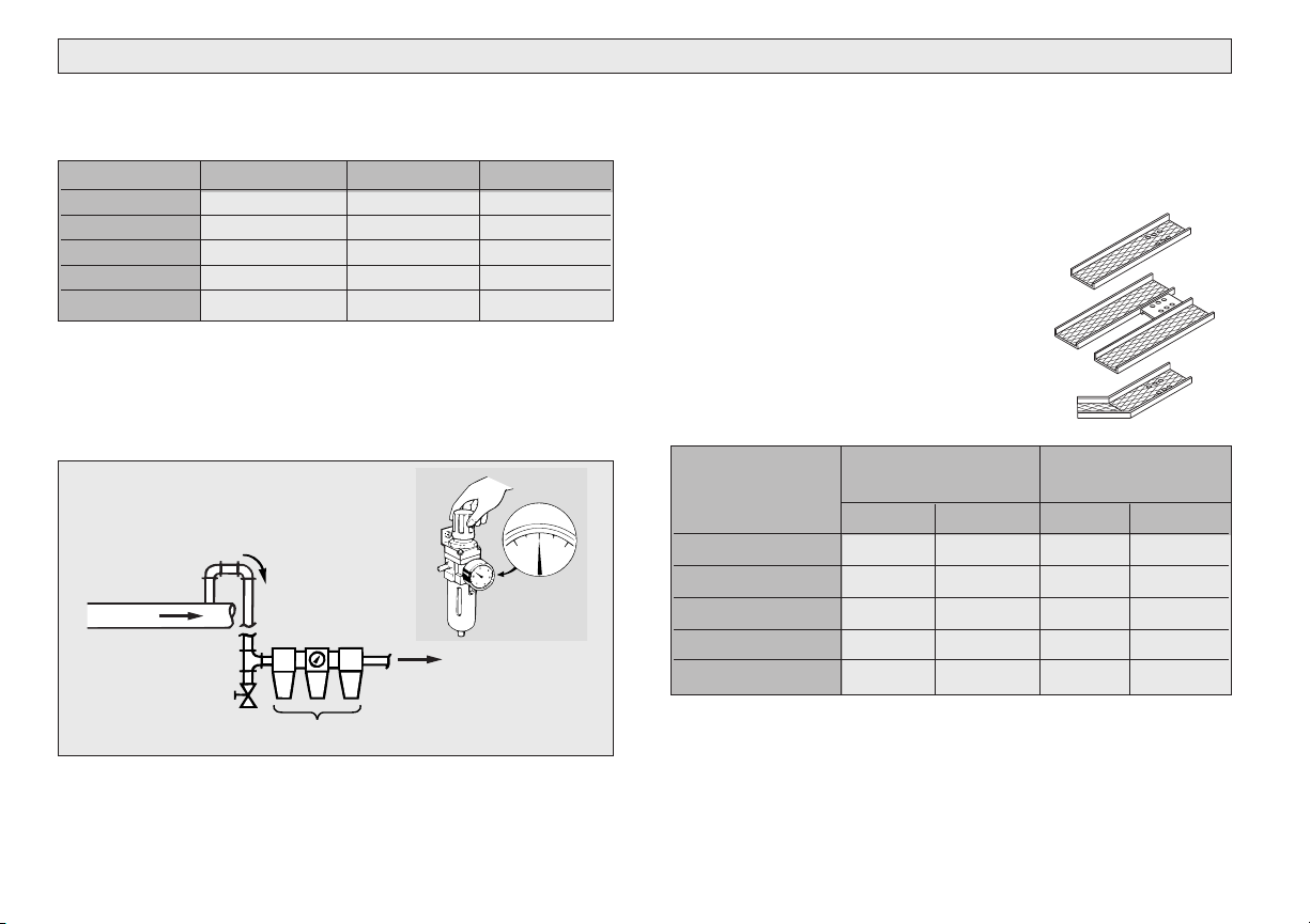
2. Air line requires use of an oil mist-type combination
Filter/Regulator/Lubricator, and Pressure Gauge. Set
pressure to 4-5 Bar (60 to 75 psi). Do not exceed 5.5 Bar
(80 psi) as excess pressure will damage the Transporter.
Recommended Air Line
Connection to Eliminate Moisture
and Particles from Main Line
Main Air Line
Drain
To Transporter
4. Connect the Air Line with flexible poly-flow tubing into
the threaded inlet. On Model TP-3 use 1/4” tubing for
1/8” NPT. Models TP-10, TP-40, TP-70 and TP-140 use
3/8” tubing for 1/4” NPT.
5. A custom “U” profile tray or chute
must be designed to handle each
specific application or tool. Any
material can be used, but we
recommend aluminum or any light
gauge material to reduce tray weight.
Maximum tray weight should not
exceed the following table data:
Max. Weight Max. Weight
Tray & Scrap
Model
Tray Only of Parts
Kg Lbs. Kg Lbs.
TP-3 1,5 3.3 3 6.6
TP-10 3 6.6 10 20
TP-40 15 33 40 80
TP-70 50 110 70 140
TP-140 100 200 140 300
Filter/Regulator/Lubricator
3. Fill the Lubricator with a good grade of hydraulic oil
such as Shell Tellus 32 or equivalent. Set the Lubricator
for one (1) drop per minute.
4
6. Fasten the tray or chute to the Transporter with metric
screws at all holes. Be sure to use spacers or washers
between the Transporter and the tray to reduce contact
friction between the moving tray and the Transporter
body. Refer to the following table.
Page 5
INSTALLATION
Model Quantity Screw size Depth
TP-3 6 M6 8mm
TP-10 6 M6 8mm
TP-40 6 M8 9mm
TP-70 6 M8 8mm
TP-140 6 M8 8mm
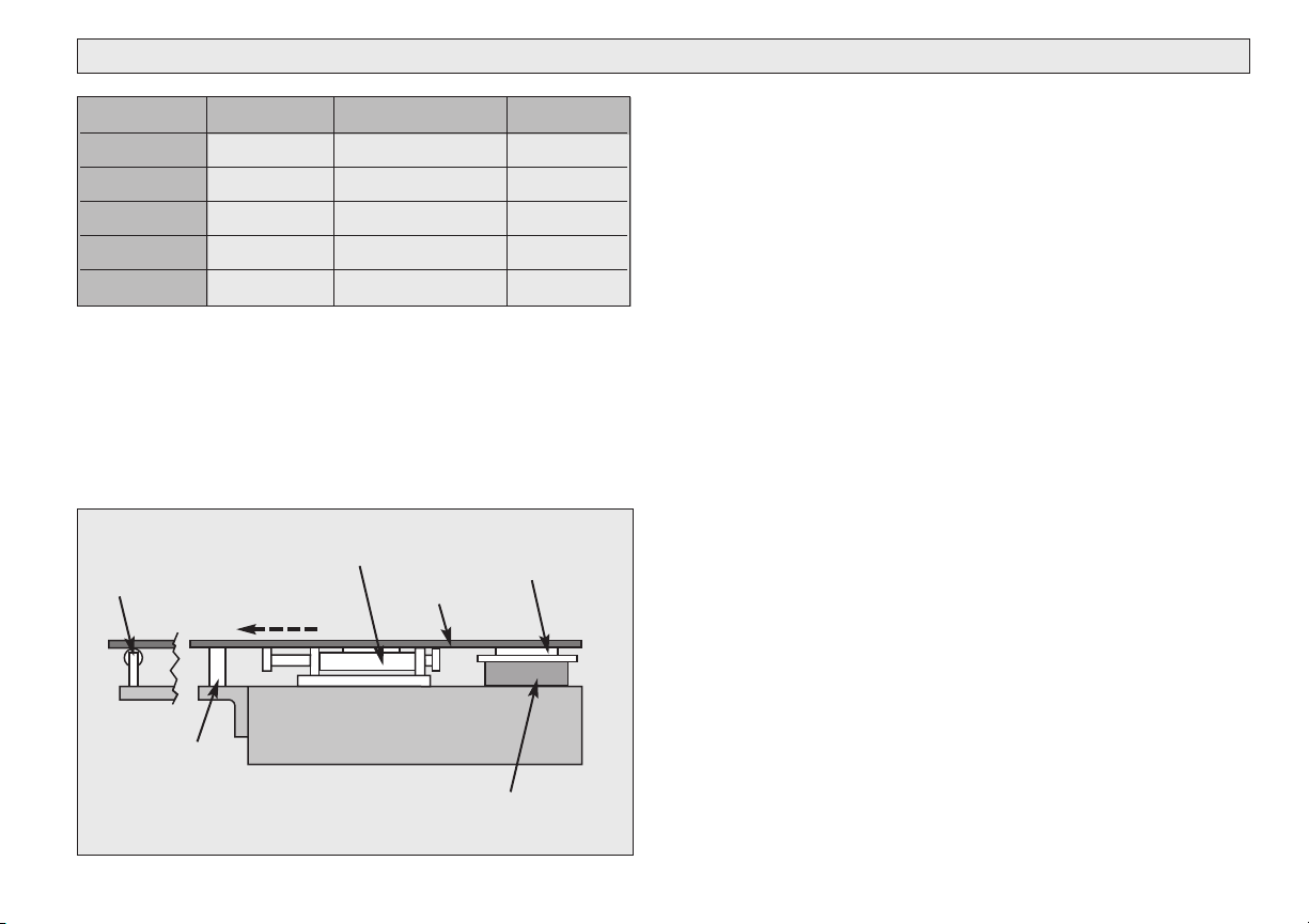
7. The Conveyor tray or chute must be supported at
both ends to minimize vibration and deflection. A block of
Delrin GP-500 or Nylon, low friction material can be used
for the tray to slide. For optimum installation, use P/A
Roller Slides to rigidly control the tray movement and
provide trouble-free operation. See page 27.
Ball Bearing
Roller
Solid Slide Low Friction
Material
Transporter
Chute
or Tray
Feed Direction
Press Bolster
Roller Slide
Spacer
8. The Speed Adjustment is preset at the factory with
the correct frequency for a light weight tray or chute.
The speed can be adjusted by turning the screw or knob
clockwise to decrease the movement on the Models
TP-3, TP-10, and TP-40. The TP-70 and TP-140 are
adjusted by turning the screw or knob counter-clockwise
to decrease the movement. Maximum speed is not
required to move parts or scrap efficiently.
9. If the TP-40 Speed Frequency is inadequate, release
the Air Regulator Rod T40-029 and gently push forward
to increase speed or backward to decrease.
10. The TP-10 may require a slight adjustment to
maintain proper speed frequency after a period of
operation. If Speed Adjustment Screw T10-405 does not
slow the unit sufficiently, it may be necessary to slightly
snug the two screws at the Air Regulator Valve T10-401.
This reduces the air being released from the valve and
decreases speed. Snugging the screws too tightly will
cause bending of the Air Regulator Rod and poor
performance.
11. Spray the same Tellus oil used in lubrication on the
pistons each week.
12. If there is a build-up of sticky oil on the conveyor tray
or if the parts or scrap are very oily, they may stick to the
surface and reduce movement. To reduce the coefficient
of friction, try dimpling the surface of the conveyor chute
with a ballpeen hammer or use a different material like
expanded metal or profiled, roll formed material.
5
Page 6

MODEL TP-3 SERVICE
Factory Repair & Rebuild Service
Return the Transporter by UPS Prepaid to our repair center.
After teardown and inspection, P/A Industries will notify you
of the recommended cost for spare parts and labor.
Disassembly Reassembly
1. Remove both Snap Rings and push the Front and
Rear Pistons inside Body.
2. Remove the Screws from the Rear Guide Holder
T3-204. Pull out together with Speed Adjustment
Knob T3-401.
3. Remove the Front Guide Holder T3-203.
4. Remove both Guide Holders (L & R) T3-201 and the
twelve (12) Ball Bearings.
5. Back out the Locking Screw T3-406 and remove the
Speed Adjustment Valve T3-603.
6. With both T3-701 Tools provided in the kit, remove the
Valve Discs and the Rod.
7. Check all “O” Rings, Springs, Discs, and Seals for
damage and replace as needed.
6
1. Install the Speed Adjustment Valve T3-603 and align
with the groove for the Locking Screw T3-406.
2. Insert the Front Piston T3-302 into the Body with the
Bumper Ring.
3. Mount the Bumper Ring and insert the Rear Piston
T3-303 into the Body.
4. Grease both Guide Holders T3-201 and put twelve (12)
Ball Bearings into both Bearing Plates T3-210. Hold
the Bearing Plates by hand while attaching Front and
Rear Holders. The Guide Holder assembly must run
smoothly in both directions without side-to-side
play.
5. Pull both Pistons T3-302 and T3-303 back into position
and secure the Snap Rings.
Page 7
MODEL TP-3 DIMENSIONAL DRAWING
1/8” NPT
4.7”
120mm
5.5”
140mm
1.3”
34mm
Speed Adjustment Knob
3.3”
83mm
.75”
19mm
Use Four
M8 Bolts for
Mounting
7”
178mm
5.1”
130mm
Use Six M6 Screws
8mm Deep Thread
for Tray Mounting
2”
51mm
5.9”
150mm
.4”
10mm
7
Page 8

TP-3 Parts Description
TP-3 Assemblies
Part No. Description Qty
T3-105 Screw 8
T3-107 Air inlet 1
T3-110 Mounting plate 1
T3-111 Mounting plate screw 4
T3-112 Spring pin 4
T3-201 Guide holder (L&R) 2
T3-203 Front guide holder 1
T3-204 Rear guide holder 1
T3-210 Sleeve retainer 2
T3-211 Stainless Steel Ball 12
T3-302 Front piston 1
T3-303 Rear piston 1
T3-307 Grease O-ring 1
*
T3-308 Grease ring 1
T3-311 Valve seal 2
*
T3-322 Rear cup seal 1
*
T3-323 Front cup seal 1
*
T3-327 Bumper ring 2
*
T3-401 Speed adjustment knob 1
T3-402 Speed adjustment rod 1
T3-404 Threaded bushing 1
T3-405 Plug 1
T3-406 Locking screw 1
T3-407 Speed valve O-ring 2
*
T3-309 Knob locking nut 1
T3-412 Speed valve O-ring 1
*
T3-601 Valverod assembly 1
T3-602 Spring assembly 2
T3-603 Valve assembly 1
T3-701 Assembly tool 2
*
T10-209 Snap ring 2
T10-313 Spring 1
T70-306 Knob O-ring (*14208-011) 1
*
Included in Repair Kit 3-001 (17269)
*
8
T3-601 Valve Rod Assembly Qty
T3-310 Valve rod 1
T3-325 O-ring 1
T3-602 Spring Assembly Qty
T3-315 Spring holder 1
T3-407 O-ring 1
T10-313 Spring 1
T3-603 Valve Assembly Qty
T3-402 Valve bar 1
T3-407 O-ring 1
T3-411 Valve 1
T3-412 O-ring 1
Page 9
TP-3 PARTS DRAWING
T3-105
T3-203
*T3-327
T3-110
T3-111
T3-323
*T3-602
T3-601
T3-325
*T3-311
*T3-602
*T3-307
T3-308
*T3-322
T3-303
T3-201
*T3-327
T3-107
* Included in Repair Kit 3-001 (17269)
T10-209
T3-302
T3-112
T3-405
T3-210
T3-211
*T3-407
T3-406
*T3-412
T3-603
T3-402
T3-204
T3-404
*T70-306 (*14208-011)
T3-401
T3-309
9
Page 10

MODEL TP-10 SERVICE
Sample
tray
shown
Disassembly
Factory Repair & Rebuild Service
Return the Transporter by UPS Prepaid to our repair center.
After teardown and inspection, P/A Industries will notify you
of the recommended cost for spare parts and labor.
1. Remove the Guide Column Locking Nuts T10-214
and the Tray Holder Screws T10-210 for the Front
Holder T10-202.
2. Pull out the Front Holder T10-202 together with the Air
Regulator Rod and Nut T10-604 and Threaded Guide
Columns T10-203.
3. Pull out the Rear Holder T10-201 together with the
Rear Pistons T10-303.
4. Remove the Air Inlet T10-601 and O-Ring 14208-119
with an 8 mm hex wrench.
5. Remove the Nut T10-305 from the Piston T10-302.
6. Remove the disc from the Valve Rod using a Phillips
head screwdriver at the T10-325, and a 13 mm socket
at the opposite end.
7. Remove the Piston Valve Assembly T10-606.
10
8. Carefully Disassemble the Piston Valve Assembly.
9. Examine all Springs, “O” Rings, and Valve Discs for
damage and replace as necessary.
Reassembly
1. Verify that the Extension, Inner Disc, and Valve Rod
must be very straight and not overtightened.
2. Assemble all components of the Piston Valve Assembly
T10-606, install in the Transporter Body, and add the
Outer Disc, noting the .015” (.38mm) movement for
proper operation.
3. If many parts have been replaced, the Transporter may
need a brief run-in period before final adjustments are
made.
Page 11

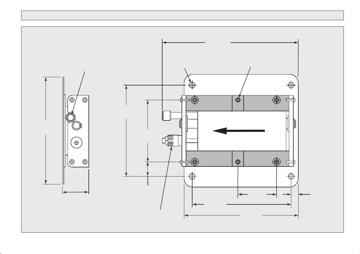
MODEL TP-10 DIMENSIONAL DRAWING
1.8”
45mm
.78”
20mm
4.9”
125mm
1/4” NPT
8.5”
216mm
4.52”
115mm
1.8”
45mm
1.2”
30mm
4.1”
105mm
2.3”
58mm
Speed
Adjustment
Screw
2.6”
67mm
Use Six M6 Screws
8mm Deep Thread for Tray Mounting
2.4”
60mm
Use Four M8 Bolts
for Mounting
11
Page 12

TP-10 Parts Description
TP-10 Assemblies
Part No. Description Qty
T10-106 Guide column sleeve 4
*
T10-201 Rear holder 1
T10-202 Front holder 1
T10-203 Threaded guide column 2
T10-204 Tray holder set (L & R) 2
T10-209 Snap ring 2
T10-210 Tray holder screw 4
T10-212 Urethane washer 4
*
T10-213 Guide column spacer 2
T10-214 Guide column locking nut 4
T10-302 Piston 1
T10-303 Rear piston 2
T10-305 Nut, piston 1
T10-311 Valve disk 2
T10-313 Spring, long 1
T10-314 Spring, short 1
T10-316 Gasket 1
*
T10-318 Valve O-ring (14208-107) 1
T10-319 Rear piston O-ring 2
*
T10-320 Plug O-ring 2
T10-324 Extension 1
T10-325 Spring retaining screw 1
T10-413 Felt 1
T10-414 Snap ring 1
T10-601 Air inlet 1
T10-602 Valve rod assembly 1
T10-603 Air regulator assembly 1
*
T10-604 Air regulator rod & nut 1
*
T10-605 Speed adjustment screw 1
T10-606 Piston assembly 1
*
T40-035 O-Ring (*14208-119) 1
*
Included in Repair Kit 10-001 (17270)
*
T10-601 Air Inlet Assembly Qty
T10-102 Air inlet 1
T40-035 O-ring 1
T10-602 Valve Rod Assembly Qty
T3-325 O-ring 1
T10-310 Valve rod 1
T10-603 Air Regulator Assembly Qty
T10-318 O-ring 1
T10-401 Air regulator 1
T10-403 Urethane washer 1
T10-404 Washer 1
T10-408 Screw 2
T10-604 Air Regulator Rod & Nut Qty
T10-321 Nut 1
T10-402 Air regulator 1
T10-605 Speed Adjustment Screw Qty
T10-405 Speed adjustment screw 1
T10-407 O-ring 1
T10-606 Piston Assembly Qty
T3-325 O-ring 1
T10-302 Piston 1
T10-310 Valve rod 1
T10-311 Disc 2
T10-313 Spring 1
T10-314 Spring 1
T10-320 O-ring 2
T10-324 Extension 1
T10-325 Screw 1
T10-327 Gasket, disc 2
12
Page 13

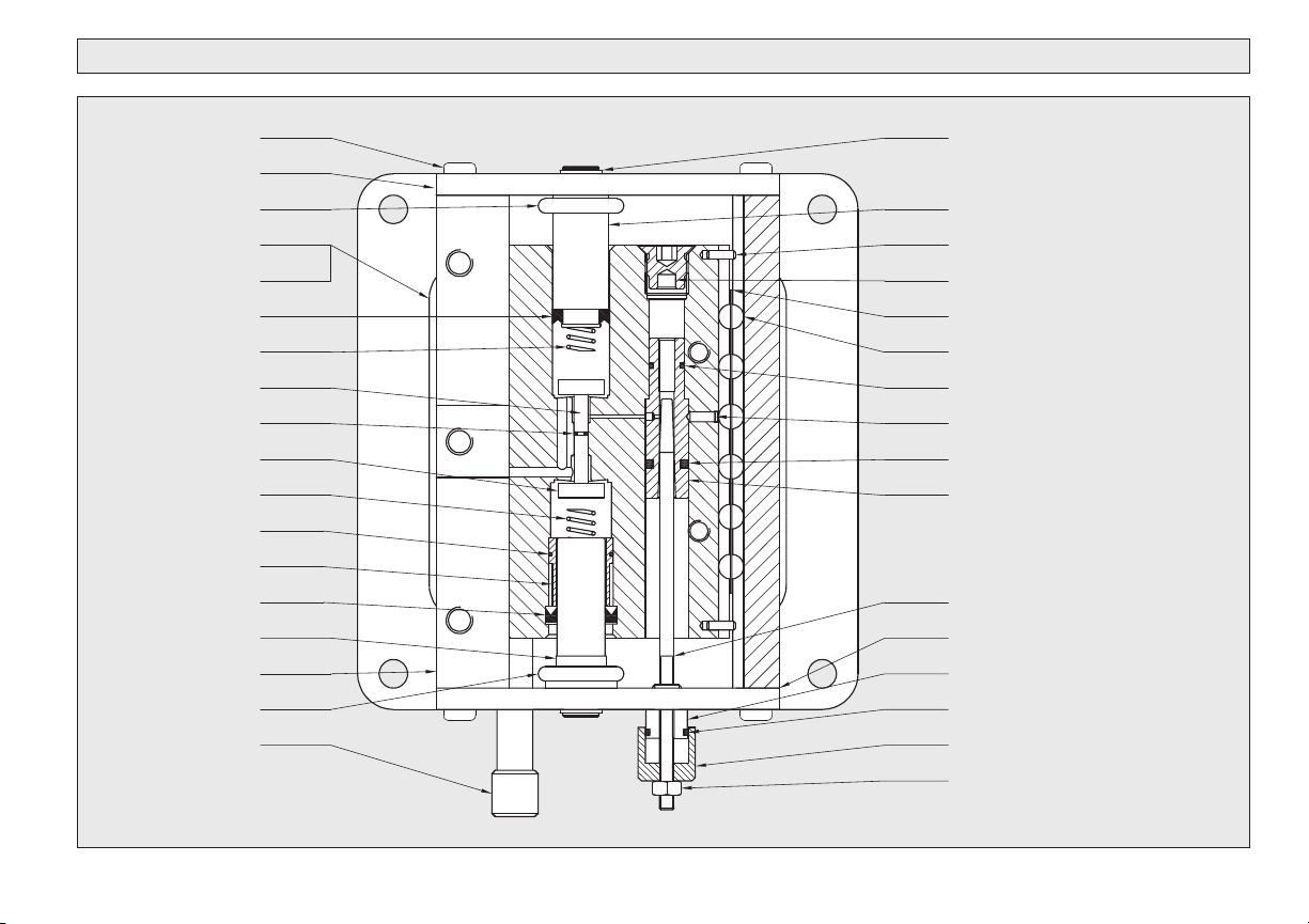
TP-10 PARTS DRAWING
T10-214
T10-202
*T10-213
T10-212
T10-414
T10-413
T10-605
T10-203
T10-106
*T10-319
T10-303
*T10-212
T10-201
T10-209
T10-210
T10-204
T10-305
*T10-316
T10-325
*T10-602
T10-313
T10-324
T10-320
T10-302
T10-314
T10-311
T10-318 (14208-107)
*T10-603
T10-602
T10-311
*T40-035(*14208-119)
T10-601
*Included in Repair Kit 10-001 (17270)
*T10-606
T3-325
Use 8 mm
Hex
Wrench
13
Page 14

MODEL TP-40 SERVICE
Disassembly
Factory Repair & Rebuild Service
Return the Transporter by UPS Prepaid to our repair center.
After teardown and inspection, P/A Industries will notify you
of the recommended cost for spare parts and labor.
1. Remove the Air Regulator Rod T40-029 by loosening
the set screw in the top of the Slide Frame and slide the
rod out. If the slide is deformed, it must be replaced.
2. Remove the two (2) Flathead Screws, which secure the
Stop Washer T40-027 to the Slide Frame. Remove Nut
T40-072 from back of Piston. Remove the Slide Frame.
3. Remove the Top Plate T40-006 which holds the Air
Regulator T40-608 and Felt Cover T40-009. Check
the Regulator O-Ring T3-407 (14208-008) for damage.
4. Remove the Air Line from Fitting T40-605. Remove the
Plug T40-601 and check the Plug O-Ring T40-037.
5. Remove Air Inlet Cap. Check O-Ring for damage.
6. Remove the eight (8) Flathead Screws T10-210 from
the bottom mounting plate and slide the Piston
Housing away from the body.
14
7. Remove the Valve Disk T40-010 by unscrewing the
Valve Disc Screw. Hold a 3mm hex wrench at the
Valve Rod Washer T40-017 to prevent rotation. It is
now possible to take out the Piston T40-019.
8. To remove the Valve Rod and Disk Assembly T40-603
from the Piston, hold the exposed Valve Disc gently in
a vise. Use the 3mm Hex Wrench and remove the
screw.
9. Replace the Long Valve Spring T40-047 and the
Short Valve Spring T40-046.
Reassembly
Reassemble in reverse order, using caution not to bend
the Valve Disc Assembly.
Page 15

MODEL TP-40 DIMENSIONAL DRAWING
3.5”
89mm
6.3”
160mm
1/4” NPT
Speed Adjustment Screw
Use Six M8 Screws
9mm Deep Thread
for Tray Mounting
9.8”
250mm
Use Two M10 Bolts
for Mounting
2.7”
68mm
3.4”
87mm
3.6”
92mm
1.3”
32mm
.4”
10mm
3.6”
92mm
5.12”
130mm
15
Page 16

TP-40 Parts Description
TP-40 Assemblies
Part No. Description Qty
T3-407 Regulator O-ring (14208-008) 1
T10-210 Flat head screw (6mm) 10
T10-605 Speed adjustment screw 1
T40-001 Foot 1
T40-006 Top plate 1
T40-008 Valve bar 1
T40-009 Felt cover 1
T40-010 Valve disk 1
*
T40-011 Valve seat 1
T40-013 Disc 1
T40-017 Valve rod washer 1
T40-019 Piston 1
T40-026 Slide frame sleeve 4
*
T40-027 Stop washer 2
T40-028 Air inlet 1
T40-029 Air regulator rod 1
T40-031 Small urethane washer 2
*
T40-035 Piston O-ring (*14208-119) 2
*
T40-036 Large O-ring (*14208-325) 1
*
T40-037 Plug O-ring 1
*
T40-038 Guide pin 2
T40-039 Valve rod cup seal 2
*
T40-041 Piston cup seal 2
*
T40-045 Compression spring 1
*
T40-046 Short valve spring 1
*
T40-047 Long valve spring 1
*
T40-049 Washer 2
T40-050 Large urethane washer 4
*
T40-051 Air connection 2
T40-052 Tube 1
T40-055 Flat head screw (5mm) 3
T40-057 Slide frame set screw 1
T40-065 Felt 2
T40-068 Bushing, long 1
T40-069 Bushing, short 1
T40-071 Threaded mounting insert (8mm) 6
T40-072 Plug nut 1
T40-073 Threaded valve seat 1
T40-074 Air inlet O-ring 1
*
T40-601 Plug assembly 1
T40-602 Cylinder front assembly 1
T40-603 Valve rod assembly 1
*
T40-604 Slide frame assembly 1
T40-605 Air tube assembly 1
T40-606 Silencer assembly 1
T40-607 Speed adjustment assembly 1
T40-608 Air regulator rod assembly 1
*
Included in Repair Kit 40-001 (17271)
*
T40-601 Plug Assembly Qty
T40-018 Plug 1
T40-037 O-ring 1
T40-049 Washer 2
T40-050 Damper 2
T40-602 Front Cylinder Assembly Qty
T40-002 Front cylinder 1
T40-016 Sleeve 1
T40-024 Spacer 2
T40-026 Bearing 4
T40-036 O-ring 1
T40-603 Valve Rod Assembly Qty
T40-008 Valve bar 1
T40-013 Disc 1
T40-070 Extension 1
T40-030 Gasket, disc 1
T40-604 Slide Frame Assembly Qty
T40-014 Slide frame 1
T40-031 Damper 2
T40-038 Guide column 2
T40-042 Snap ring 2
T40-054 Screw 2
T40-057 Screw 1
T40-071 Mounting insert 6
T40-605 Air Tube Assembly Qty
T40-051 Air connection 2
T70-052 Tube 1
T40-606 Silencer Assembly Qty
T40-059 Mantel 1
T70-067 Washer 1
T40-607 Speed Adjustment Assembly Qty
T10-407 O-ring 1
T10-405 Screw 1
T40-060 Valve 1
T40-608 Air Regulator Rod Assembly Qty
T3-407 O-ring 1
T40-029 Air regulator rod 1
T40-058 Air regulator 1
16
Page 17

TP-40 PARTS DRAWING
T40-028
*T40-074
*T40-010
*T40-045
T40-011
*T40-039
T40-073
T40-029
T40-006
T40-058
*T40-608
T3-407
T40-009
T10-605
*T40-603
*T40-041
T40-001
*T40-035
T40-019
*T40-036
T40-047
T40-068
T40-017
T10-210
T40-055
T40-601
*T40-037
T40-072
T40-065
T40-069
*T40-046
T40-602
T40-055
T40-071
T40-604
T40-057
*Included in Repair Kit 40-101 (17271)
T40-607
T40-606
T40-027
*T40-050
*T40-026
T40-038
*T40-031
17
Page 18

MODEL TP-70 SERVICE
Disassembly
Factory Repair & Rebuild Service
Return the Transporter by UPS Prepaid to our repair center.
After teardown and inspection, P/A Industries will notify you
of the recommended cost for spare parts and labor.
1. Remove the Spanner Nut T70-216 from the Rear
Piston T70-601 and push the Piston inside the Cylinder.
2. Remove the eight (8) holder screws with a T40 Torx
wrench. Loosen the eight (8) Set Screws T70-436.
There is no need to remove the set screws.
3. Pull the Front and Rear Holders away from the Body
while holding the Outer Guide Assemblies to prevent
the Bearings from being lost. The Front Piston
T70-602 and Shock Absorber T70-407 will come out
with the Front Holder. The Speed Adjustment
Assembly will come out with the Rear Holder.
4. Now remove the Front and Rear Retaining Plates.
The Rear Piston can now be removed from the Body.
5. Back out the Speed Adjustment Valve Locking
Screw T70-311 and remove the Speed Adjustment
Valve T70-604.
18
6. Unscrew Valve Seals T40-010 and pull the seals
out. Check all seals and O-rings for wear, make
sure valve seals are flat, and Valve Rod T70-603
is straight.
Reassembly
When reassembling, take care with the following:
1. Install Speed Adjustment Valve and align indent
for the Speed Adjustment Valve Locking Screw.
2. Remember to install the Front and Rear Cylinder
Urethane Washers T70-257 and T70-259.
3. Use the T70-436 Set Screws to adjust out any
play or looseness in the Slide Assembly before
tightening the Holder Screws.
Page 19

MODEL TP-70 DIMENSIONAL DRAWING
1.8”
46mm
3.0”
77mm
5.5”
140mm
3.9”
99mm
5.0”
127mm
2.8”
70mm
1.6”
41mm
12.8”
325mm
2.5”
64mm
Typ.
Use Six M8 Bolts
for Mounting
Speed
Adjustment
Knob
1.5”
38mm
1.2”
30mm
Typ.
1/4” NPT
1.1”
28mm
.28”
7mm
.94”
24mm
2.0”
51mm Typ.
Use Six M8 Screws
8mm Deep Thread
for Tray Mounting
19
Page 20

TP-70 Parts Description
TP-70 Assemblies
Part No. Description Qty
T3-407 Cylinder rod O-ring (14208-008) 2
T10-319 Speed adjustment knob O-ring 1
*
T10-320 Plug O-ring 1
*
T40-010 Valve seals 2
*
T40-037 O-ring 1
*
T40-045 Compression spring 1
*
T40-047 Compression spring long assembly 2
*
T70-105 Threaded mounting insert (8mm) 6
T70-153 Bearing retainer (5mm) 2
T70-154 Ball bearing (5mm) 56
T70-215 Cup seal (front & rear) 2
*
T70-216 Spanner nut (front & rear) 2
T70-217 Snap ring 2
T70-220 Piston urethane washer 2
*
T70-253 Rear spring guide 1
T70-254 Front spring guide 1
T70-257 Front cylinder urethane washer 1
*
T70-259 Rear cylinder urethane washer 1
*
T70-302 Speed adjustment rod 1
T70-303 Speed adjustment knob 1
T70-306 Speed adjustment valve O-ring, small (*14208-011) 1
*
T70-310 Knob locking nut 1
T70-311 Speed adjustment valve lock screw 1
T70-320 Washer 1
T70-321 Rear threaded bushing 1
T70-322 Silencer 1
T70-403 Rear retaining plate 1
T70-404 Front retaining plate 1
T70-406 Front threaded bushing 1
T70-407 Shock absorber 1
T70-408 Shock absorber locking nut 1
T70-410 Holder screw 8
T70-411 Retaining plate screw 12
T70-413 Shock absorber plug 1
T70-433 Rear holder 1
T70-434 Front holder 1
T70-436 Screw 8
T70-601 Front piston assembly 1
T70-602 Rear piston assembly 1
T70-603 Valve Rod assembly 1
*
T70-604 Valve assembly 1
T70-605 Ball guide assembly 1
Included in Repair Kit 70-001 (17272)
*
20
T70-601 Front Piston Assembly Qty
T40-047 Spring, long 1
T70-211 Front piston 1
T70-215 Cup seal 1
T70-217 Snap ring 1
T70-253 Spring guide 1
T70-602 Rear Piston Assembly Qty
T40-047 Spring, long 1
T70-212 Rear piston 1
T70-215 Cup seal 1
T70-217 Snap ring 1
T70-254 Spring guide 1
T70-603 Valve Rod Assembly Qty
T3-407 O-ring 2
T70-251 Valve rod 1
T70-604 Valve Assembly Qty
T40-037 O-ring 1
T70-302 Valve rod 1
T70-306 O-ring 1
T70-308 Valve 1
T70-605 Ball Guide Assembly Qty
T70-153 Ball retainer (5mm) 1
T70-154 Ball (5mm) 28
T70-426 Ball guide 1
T70-428 Screw 7
T70-435 Guide column 1
T70-437 Ball guide 1
Page 21

TP-70 PARTS DRAWING
T70-216
T70-434
T70-410
T70-220
T70-602
T70-411
T70-404
*T70-215
*T40-047
T70-153
T70-154
T70-257
T40-010
T70-605
T70-105
*T40-010
T70-259
T70-217
*T70-215
T70-601
T70-253
T70-403
*T40-047
T70-436
T70-433
T70-216
T70-408
T70-320
T70-406
T70-407
T70-217
T70-254
T70-413
T10-320
*T40-045
*T70-603
*T3-407
*T70-306
T70-311
T40-037
T70-604
T70-322
T70-302
T70-321
*T10-319
T70-303
T70-310
*Included in Repair Kit 70-001 (17272)
21
Page 22

MODEL TP-140 SERVICE
Disassembly
Factory Repair & Rebuild Service
Return the Transporter by UPS Prepaid to our repair center.
After teardown and inspection, P/A Industries will notify you
of the recommended cost for spare parts and labor.
1. Remove the two (2) Spanner Nuts T70-216 from the
Rear Piston assembly T70-601 and T140-211 and
push the Pistons inside the Cylinder.
2. Remove the eight (8) holder screws with a T40 Torx
wrench. Loosen the eight (8) Set Screws T70-436.
(No need to remove).
3. Pull the Front and Rear Holders away from the Body
while holding the Outer Guide Assemblies to prevent
the Bearings from being lost. Remove the Front Piston
assembly T70-602 and Rear Piston T140-212.
Together, with the two (2) Shock Absorbers T70-407,
they will come out with the Front Holder. The Speed
Adjustment Assembly will come out with the Rear
Holder.
4. Now remove the Front Retaining Plate T140-404.
The Rear Piston can now be removed from the Body.
22
5. Unscrew Sleeve T140-326 using an 8 mm Hexagon
Wrench. Then pull out the Speed Adjustment Valve
T140-308.
6. Unscrew Valve Seals T40-010 and pull out. Check all
seals and o-rings for wear, make sure Valve Seals are
flat, and Valve Rod T70-603 is straight.
Reassembly
When reassembling, take care with the following:
1. Install the Speed Adjustment Valve T140-308 and
tighten Sleeve T140-326 using an 8 mm Hexagon
Wrench. Do not overtighten.
2. Don’t forget to install the Front and Rear Cylinder
Urethane Washers T70-257 and T70-259.
3. Use the T70-436 Set Screws to adjust out any play or loose
ness in the Slide Assembly before tightening the Holder Screws.
Page 23

MODEL TP-140 DIMENSIONAL DRAWING
3.0”
77mm
7.6”
192mm
2.9”
75mm
1/4” NPT
5.8”
148mm
4.8”
122mm
7”
179mm
1.1”
28.5mm
2.5”
63.5mm
Typ.
51mm
12.8”
325mm
2.0”
Typ.
Use Six M8 Bolts
for Mounting
Speed
Adjustment
Knob
Use Six M8 Screws
8mm Deep Thread
for Tray Mounting
23
Page 24

TP-140 Parts Description
TP-140 Assemblies
Part No. Description Qty
T3-407 Cylinder rod O-Ring (14208-008) 2
T10-319 Speed adjustment knob O-Ring 1
*
T10-320 Plug O-ring 2
*
T40-010 Valve seals 2
*
T40-045 Compression spring 2
*
T40-047 Valve spring 2
*
T70-153 Bearing retainer (5mm) 2
T70-215 Cup seal (front & rear) 4
*
T70-216 Spanner nut (front & rear) 4
T70-217 Snap ring 2
T70-220 Piston urethane washer 4
*
T70-253 Rear spring guide 1
T70-254 Front spring guide 1
T70-303 Speed adjustment knob 1
T70-310 Knob locking nut 1
T70-320 Washer 2
T70-406 Front threaded bushing 2
T70-407 Shock absorber 2
T70-408 Shock absorber locking nut 2
T70-411 Retaining plate screw 8
T70-413 Shock absorber plug 2
T70-436 Screw 8
T70-601 Front piston assembly 1
T70-602 Rear piston assembly 1
T70-603 Valve rod assembly 1
*
T70-605 Ball guide assembly 1
T140-105 Threaded mounting insert (8mm) 6
T140-211 Front piston 1
T140-212 Rear piston 1
T140-302 Speed adjustment Rod 1
T140-308 Speed adjustment valve 1
T140-326 Sleeve 1
T140-401 Rear holder 1
T140-402 Front holder 1
T140-404 Front retaining plate 1
T140-601 Front piston assembly 1
T140-602 Rear piston assembly 1
T140-603 Silencer assembly 1
Included in Repair Kit 140-001 (18914)
*
T140-601 Front Piston Assembly Qty
T140-211 Piston 1
T70-215 Cup seal 1
T140-602 Rear Piston Assembly Qty
T140-212 Rear piston 1
T70-215 Cup seal 1
T140-603 Silencer Assembly Qty
T140-324 Damp bushing 1
T140-502 Lock 1
T140-503 Silencer 1
T140-504 Felt 1
T40-045 Spring 1
T70-601 Front Piston Assembly Qty
T40-047 Spring, long 1
T70-211 Front piston 1
T70-215 Cup seal 1
T70-217 Snap ring 1
T70-253 Spring guide 1
T70-602 Rear Piston Assembly Qty
T40-047 Spring, long 1
T70-212 Rear piston 1
T70-215 Cup seal 1
T70-217 Snap ring 1
T70-254 Spring guide 1
T70-603 Valve Rod Assembly Qty
T3-407 O-ring 2
T70-251 Valve rod 1
T70-605 Ball Guide Assembly Qty
T70-153 Ball retainer (5mm) 1
T70-154 Ball (5mm) 28
T70-426 Ball guide 1
T70-428 Screw 7
T70-435 Guide column 1
T70-437 Ball guide 1
24
Page 25

TP-140 PARTS DRAWING
T140-402
T140-410
*T70-220
T70-602
T140-404
T70-411
*T70-215
T40-047
T70-153
T70-154
*T70-257
T40-010
*T70-603
*T3-407 (*14208-008)
T70-605
*T40-010
T70-259
T70-217
T70-215
T70-601
T70-253
T140-112
*T40-047
T70-436
T70-408
T70-407
T70-320
T70-406
T140-212
T70-220
T70-254
T70-413
*T10-320
T140-105
*T40-045
T140-308
T140-326
T140-211
T140-302
T70-220
T140-401
T70-216
*Included in Repair Kit 140-001 (18914)
T140-603
*T10-319
T70-303
T70-310
25
Page 26

TECHNICAL DATA
Model Pressure Consumption Stroke Feed Chute Level Weight capacity Chute
TP-3
TP-10
TP-40
TP-70
Air Air of of of Feed Sound portation weight
60-80 psi 8.8 cfm .9 in. 29-33 fpm 8° 56 dB (A) 3 lbs 6.4 lbs 3.2 lbs
4–5,5 bar 5 l/min 23 mm 8–10 m/min 8° 56 dB (A) 1,4 kg 3 kg 1,5 kg
60-80 psi 19.4 cfm .9 in. 29-33 fpm 8° 60 dB (A) 6 lbs 21.4 lbs 6.4 lbs
4–5,5 bar 11 l/min 23 mm 8–10 m/min 8° 60 dB (A) 2,8 kg 10 kg 3 kgs
60-80 psi 55 cfm 1.1 in. 29-33 fpm 8° 70 dB (A) 15 lbs 85.6 lbs 32 lbs
4–5,5 bar 31 l/min 27 mm 8–10 m/min 8° 70 dB (A) 7,2 kg 40 kg 15 kg
60-80 psi 78 cfm 1.1 in. 29-33 fpm 8° 68 dB (A) 12 lbs 150 lbs 107 lbs
4–5,5 bar 44 l/min 27 mm 8–10 m/min 8° 68 dB (A) 5,5 kg 70 kg 50 kg
Length Rate incline Trans- Max.
Max.
26
TP-140
60-80 psi 74 cfm 1.1 in. 29-33 fpm 8° 62 dB (A) 17 lbs 300 lbs 214 lbs
4–5,5 bar 42 l/min 27 mm 8–10 m/min 8° 62 dB (A) 8 kg 140 kg 100 kg
Air consumption is measures at a pace of 120 strokes per minute and an air pressure of 4 bars (60psi).
Page 27

Roller Slide Tray Support Options
Model RS-1
#17918
Slide Rail
Stopper
Mounting Plate
Roller Slide Dimensions
Model RS-1
#17918
Tray
Mounting
Surface
Model RS-2 #17432-01
J
E
D
F
Tray Mounting
Surface
J
D
M
K
A
B
C
Ball Bearings
B
E
M4 THRU
H
Model RS-2
#17432-01
A
C
Bottom View
Note: Cut slide rail to desired length.
H
L
M
N
N
G
Slide Rail
K
1
/2K
Mounting Plate
Guide Plate
Stopper
Ball Bearings
METRIC - mm USA - inches
RS-1 RS-2 RS-1 RS-2
A 105 100 4.20 3.94
B 6.8 15 .27 0.59
C 86 70 3.38 2.76
D 35 60 1.375 2.36
E 35 5 .68 0.20
F– 50 – 1.97
G– 50 – 1.97
H–100 – 3.94
J 9.5 16.2 .375 0.64
K 24 37 .93 1.46
L–300 – 11.8
M 32 Max 2.3 1.25 Max 0.09
N 4.5 4.6 x 5.3 .175 0.18 x 0.21
SEAL
27
Page 28

P/A INDUSTRIES INC., 522 Cottage Grove Road, Bloomfield, CT 06002-3191 USA
®
www.pa.com
Toll-Free: 1-800-243-8306, Worldwide: 1-860-243-8306, Fax: 1-860-242-4870, E-mail: sales@pa.com FORM 1053 11-07
 Loading...