

Page 1
Page 2

ULTRA EDGE SERVO ROLL FEED 2/14/2003
TABLE OF CONTENTS
DESCRIPTION PAGE
1 INTRODUCTION............................................................................................................................................................................ 3
2 THEORY OF OPERATION........................................................................................................................................................... 3
2.1 MECHANICAL ASSEMBLY.............................................................................................................. 3
2.2 ELECTRICAL CONTROL ENCLOSURE ASSEMBLY ......................................................................... 3
2.3 SERVOMOTOR/DRIVE OPERATION............................................................................................ 4
2.4 TOOL STORAGE OPERATION ................................................................................................... 5
2.5 PLS OPERATION (OPTIONAL)....................................................................................................... 5
2.6 STRIP ENCODER-OPERATION (OPTIONAL) ............................................................................... 6
3 PROGRAMMING THE ULTRA EDGE SERVO ROLL FEED SYSTEM - OVERVIEW .......................................................7
3.1 “OPER” KEY........................................................................................................................................ 8
3.2 “TOOLS” KEY ..................................................................................................................................... 8
3.3 “SETUP” KEY.................................................................................................................................... 13
4 HOW TO …................................................................................................................................................................................... 16
4.1 HOW TO CREATE A NEW TOOL................................................................................................. 16
4.2 HOW TO EDIT AN EXISTING TOOL............................................................................................ 18
4.4 HOW TO DELETE A TOOL............................................................................................................ 23
4.5 HOW TO ACTIVATE A TOOL........................................................................................................ 25
4.6 HOW TO EDIT “SETUP” PARAMETERS .................................................................................... 26
4.7 HOW TO EDIT LENGTH FROM OPERATOR SCREEN........................................................... 26
4.8 HOW TO EDIT COUNT FROM OPERATOR SCREEN............................................................. 26
4.9 HOW TO MICRO ADJUST LENGTH USING LENGTH ADJUSTMENT................................. 26
4.10 HOW TO SYNCHRONIZE PRESS AND PLS ............................................................................. 27
4.11 HOW TO SET CAM “ON” AND “OFF” PARAMETER ................................................................ 27
5 OPERATING THE ULTRA EDGE SERVO FEED................................................................................................................... 27
5.1 PROGRAMMING.............................................................................................................................. 27
5.2 PRIORITY MODE............................................................................................................................. 28
5.3 “JTL” (JOG TO LENGTH) MODE ................................................................................................. 28
5.4 “AUTO / MANUAL” MODE.............................................................................................................. 28
5.5 STRIP ENCODER OPERATION .................................................................................................... 29
5.6 TROUBLESHOOTING GUIDE....................................................................................................... 31
5.7 ERROR CODES ............................................................................................................................... 32
WARNING ........................................................................................................................................................................................ 34
SAFETY PROGRAM ......................................................................................................................................................................34
WARRANTY.....................................................................................................................................................................................34
2
Page 3

ULTRA EDGE SERVO ROLL FEED 2/14/2003
RECEIVING INSPECTION
BEFORE REMOVING UNIT FROM ITS PACKAGING, CHECK FOR VISUAL DAMAGE,
ESPECIALLY IF CRATE, SKID, OR CARTON HAS BEEN DAMAGED IN TRANSIT. ANY
DAMAGE CAUSED IN SHIPMENT SHOULD BE IMMEDIATELY REPORTED TO THE
CARRIER. IF UNIT APPEARS IN SATISFACTORY CONDITION, REMOVE ALL PACKING
AND WIPE RUST PREVENTIVE FROM ROLLERS WITH MILD SOLVENT.
1 INTRODUCTION
IMPORTANT
Before turning the system on for the first time, verify that installation has been completed according to
the Installation manual and the main input voltage is 110 VAC, single phase.
The P/A Industries Ultra Edge Servo Roll Feed is a state of the art AC Servo feed, which simplifies Operator
adjustments to feed parameters. These Operator adjustments are entered into the control memory through the keypad.
With the use of positional limit switches, the press signals the feeder when to begin moving the strip, when the feed
pitch must be completed, when the press has completed its down stroke, and with optional pneumatic pilot release,
when to open the rolls for piloting.
The mechanical simplicity, accuracy, and ease of use of the Ultra Edge Servo Roll Feed will help to improve your
quality and production for years to come.
2 THEORY OF OPERATION
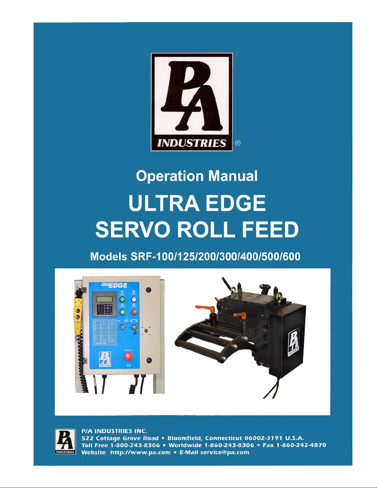
2.1 MECHANICAL ASSEMBLY
Mechanical assembly consists of:
1) Adjustment/Mounting bracket
2) Feeder
3) Servomotor
4) Mechanical pilot release actuator (optional)
5) PLS – Programmable Limit Switch (optional)
2.2 ELECTRICAL CONTROL ENCLOSURE ASSEMBLY
Electrical control enclosure consists of:
1) Control switches/buttons/relays
2) Power supply, 24 VDC/5 VDC
3) Servo drive
4) Data entry terminal Cabling
5) Jog Pendant
3
Page 4
ULTRA EDGE SERVO ROLL FEED 2/14/2003
ALL ULTRA ADVENTAGE SERVO ROLL FEED CONTROLS ARE CONVENIENTLY
LOCATED ON THE FRONT SIDE OF THE ELECTRICAL ENCLOSURE
CONTROL/DEVICE DESCRIPTION
Power On/Reset button Turns controller on, resets the servo drive.
In Position indicator light, white Turns on when move is complete and motor is holding position.
Cycle Start illuminated button, green Turns controller into “Auto” mode from “Manual” mode, starts cycling.
Cycle Stop button, red: Stops cycling and returns the controller into “Manual” mode.
“JTL / Manual-Auto” mode selector switch: Turns controller into “Manual” or “JTL” (Jog To Length) mode.
Emergency Stop mushroom button, red Shuts controller off
Operator terminal Displays controller’s data and enters data into controller.
“Programming Locked / Unlocked” key-switch Locks access to programming.
Forward / Reverse remote jog pendant Pendant is attached to the enclosure through retractile cable.
2.3 SERVOMOTOR/DRIVE OPERATION
The introduction of servomotor technology to the press roll feed has pushed the limits of accuracy, adjustability,
and performance to levels previously unattainable.
The following example is based on the Ultra Edge Servo Roll Feed Standard, US (SRF-125, 200, 300, 400, 500,
600) models. The actual numbers for SRF-100 or metric models are different.
Each revolution of the servomotor produces 1048576 encoder pulses. Every 2.909 revolutions of the servo motor shaft
produce 1 revolution of the feed rollers. The circumference of the lower roll is approximately 11.138 inches.
When a new feed pitch is entered into the system, the built in computer calculates the correct number of electronic
“pulses” it must receive from the motor mounted encoder in order to rotate the feed rolls the correct distance.
Example: If a feed pitch/length of 11.138 inches is entered into the feeder, this will result in exactly one revolution of
the feed rolls. The motor will accelerate and turn 2.909 turns. This will produce (2.909 x 1048576 = 3050307) pulses
of the encoder. The feeder will decelerate and stop, when 3050307 pulses are detected. The feeder is now in position.
4
Page 5

ULTRA EDGE SERVO ROLL FEED 2/14/2003
The result is an accurately positioned strip exactly 11.138 inches from its starting point. This entire process happens
in milliseconds.
2.4 TOOL STORAGE OPERATION
The tool storage feature allows for storing of parameters that are different from tool to tool. It takes just a few seconds
to activate feeding parameters associated with a certain tool number. Maximum 200 tools can be stored. Tools are
organized by Tool number, which is user definable and can contain up to 7 digits.
Each tool consists of the following parameters:
-Length;
- Batch Count;
- Speed;
- Dwell;
- Accel;
- Decel;
- Feed Cam “On”;
- Feed Cam “Off”;
- Reset Cam “On”;
- Reset Cam “Off”;
- Pilot Release Cam “On”;
- Pilot Release Cam “Off”;
- Aux1. Cam “On”;
- Aux1. Cam “Off”;
- Aux2. Cam “On”;
- Aux2. Cam “Off”;
- Aux3. Cam “On”;
- Aux3. Cam “Off”;
NOTE: Cam settings are available only with PLS version of software.
Consider the tool storage as a part of the servo drive’s NVRAM memory that is dedicated to storing information of all
the existing tools. In order to run a tool, it must be activated. Tool activation is an internal drive procedure of making
a copy of the tool, and placing it in a different memory location. This copy, not the tool in the tool storage, is used to
perform material feeding. “Tool #NNN is active” means only that the feed running parameters are copied from this
tool.
A tool in the tool storage area and its copy, are edited independently, with the difference, that only two of the copy’s
parameters are accessible – Length and Batch Count. These are accessible from the Operator screen. In order to edit
the rest of the parameters of the tool, the tool in tool storage must be edited, and then, reactivated.
NOTE: Deleting an active tool from the tool storage causes deletion of its copy as well.
NOTE: An active tool remains active after power recycling.
2.5 PLS OPERATION (OPTIONAL)
The PLS, Programmable Limit Switch consists of an intelligent encoder and the cable that connects the encoder to
the servo drive. The encoder is mounted on the press and its shaft is coupled or belted to the crankshaft with a one to
one (1:1) ratio. On every power-up, the encoder turns into the intelligent mode (for approximately 10 msec) to read
its actual position and store it in the servo drive.
The encoder then turns into the incremental mode, sending the count signals to the servo drive proportionally to the
angle of the move (1024 counts per revolution). The servo drive software, having the start point position of the
5
Page 6

ULTRA EDGE SERVO ROLL FEED 2/14/2003
encoder shaft, constantly calculates (updates) its current position. The position of the press crankshaft is determined
through the offset parameter, which is the position of the encoder shaft when the press is in its 0 degree position
(TDC).
Thus, at every point of the stroke, the servo drive knows where the crankshaft is. The servo drive controls six cams
simultaneously, turning them on and off accordingly to the cam settings.
Since the PLS encoder is connected directly to the servo drive, there is no need to wire connections for the Feed Cam
and the Reset Cam outputs. These outputs are software type outputs.
The rest of the cam outputs are hardware type and require wiring of output relays to the desired mechanisms, such as a
pilot release solenoid, parts blow-off, tool lubricator, etc. The cam settings (On/Off angles) are set through the
operator terminal. They are part of the tool settings.
NOTE: All PLS outputs are active as soon as SRF power is turned on.
2.6 STRIP ENCODER-OPERATION (OPTIONAL)
The Strip Encoder assembly consists of:
a. 300mm diameter knurled measuring wheel
b. 10,000 pulses per revolution encoder
c. Air valve with manual actuator
d. Air cylinder slide
e. Magnetic sensor
The encoder measuring wheel is coupled to the encoder and both are mounted on the slide. The slide can be moved up
and down by applying air pressure (80-100 PSI) to the air cylinder. The magnetic sensor is used to indicate the
up/down position of the measuring wheel.
The encoder output results in 40,000 pulses (counts) per revolution for a final resolution of 3386 counts per inch of
linear strip movement.
While the measuring wheel is in its up position, the servo roll feed acts as if there is no strip encoder attached to it, and
all of the SETUP parameters associated with a strip
The Strip Encoder may be used to control or to check the position of the material strip.
The P/A Industries® servo roll feed with optional Strip Encoder comes standard with the ability to function in one of
the two modes.
encoder operation are inactive.
1. CONTROL MODE
In this mode the position control of the material motion is done through Strip Encoder feedback. The velocity control
is based on data coming from both, Strip Encoder and Motor Mounted Encoder.
This mode provides relatively slower speed performance, due to the increase in computation of the velocity control
algorithm.
2. CHECK MODE
In this mode the full control of the material motion (Acceleration, Deceleration, Speed and positioning) is done
through the motor mounted encoder. When a move is complete, the Strip Encoder positioning control checks if the
material is within the Length Check tolerance, if it is not, "Position Error" is displayed, and Auto mode is turned off.
6
Page 7
ULTRA EDGE SERVO ROLL FEED 2/14/2003
3 PROGRAMMING THE ULTRA EDGE SERVO ROLL FEED SYSTEM OVERVIEW
NOTE: Before attempting any programming, make sure that the “PROGRAMMING LOCKED /
UNLOCKED” key switch is in the “Unlocked” position.
NOTE: After power shutdown, WAIT for 5 seconds before powering up the Feed.
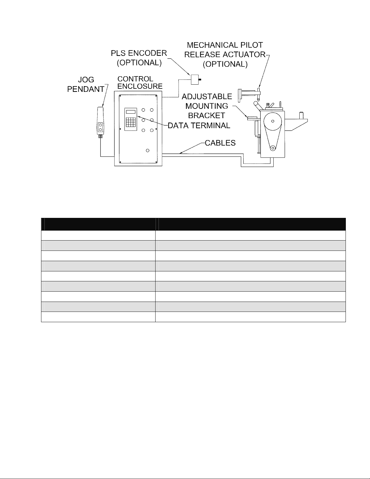
Turn on the main power disconnect switch. This applies power to the control power supply. Press the green Power
On push-button. The button will illuminate and the OPERATOR terminal display will be visible.
Wait for the IN POSITION light to illuminate.
Press any key to begin.
P / A I n d u s t r i e s
R e a l l y C o o l F e e d
V e r s i o n 1 . 0 0 s t d
H i t a n y k e y t o c o n t .
NOTE: The OPERATOR terminal has three mode keys, they are:
● “OPER”
● “TOOLS”
● “SETUP”
NOTE: ▓ The flashing cursor is waiting for the value to be entered.
NOTE: < The pointer prompts to press the “ENTER” key.
NOTE: To confirm any value, press “ENTER”.
7
Page 8

ULTRA EDGE SERVO ROLL FEED 2/14/2003
3.1 “OPER” KEY
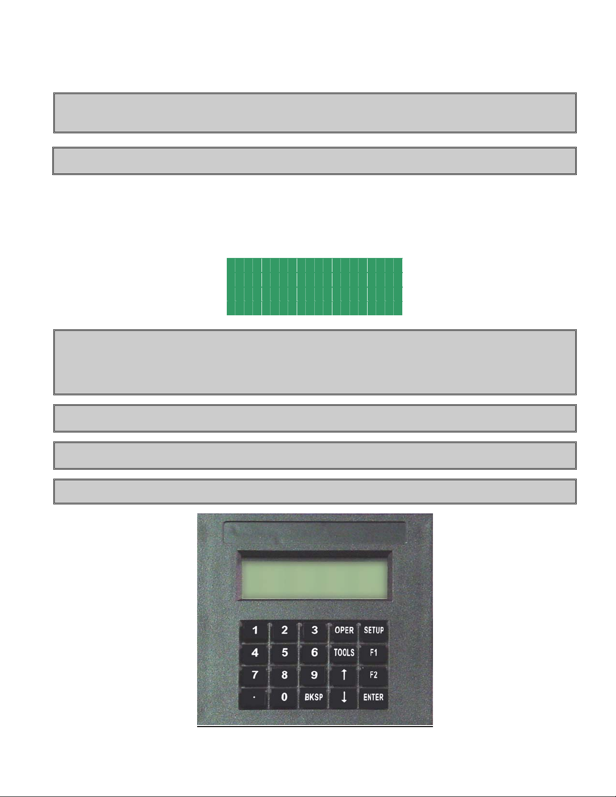
“OPER” key controls appearance of two screens: STATUS screen and OPERATOR screen.
STATUS screen shows:
T o o l # 1 P o s : 1 8 2
M a n u a l M o d e
3 0 / C o n t . R u n
P r e s s a M o d e K e y
• Active tool number. In case there is no active tool “No Tool!” message displayed instead
• Current press position in degrees. Available only on PLS model
• Current mode of the feed
• Batch count, current and commanded
NOTE: When the feed is turned into Auto mode it displays current press speed (in strokes per minute) instead
of current press position.
T o o l # 1 S p d : 3 8 4
A u t o M o d e
3 0 / C o n t . R u n
P r e s s a M o d e K e y
OPERATOR screen shows and allows editing the following parameters:
L e n g t h 1 . 0 0 0
C o u n t C o n t . R u N
L e n g t h A d j u s t m e n t <
P r e s s O P E R t o e x i t
• Length
• Batch count command
• Length micro adjustment
Every time the “OPER” key is pressed it toggles between the STATUS screen and the OPERATOR screen.
3.2 “TOOLS” KEY
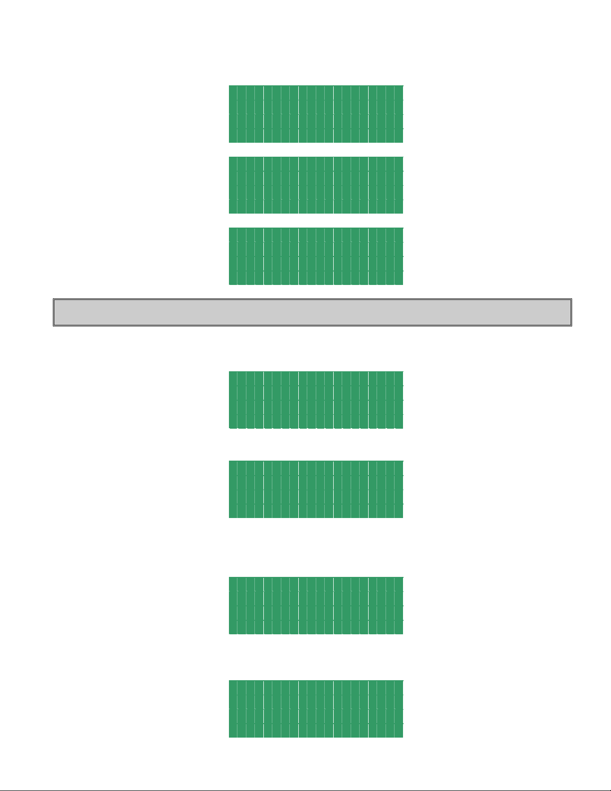
“TOOLS” key controls appearance of TOOL STORAGE screens. Press the “TOOLS” key to open the first screen.
This allows the Operator to chose a Tool Storage operation: “Edit Tool”, “Activate Tool”, or “Create New Tool”.
E d i t T o o l
A c t i v a t e T o o l <
C r e a t e N e w
P r e s s T O O L S t o e x i t
Position the pointer on desired line, using “↑” and “↓” keys , and press the “ENTER” key.
8
Page 9
ULTRA EDGE SERVO ROLL FEED 2/14/2003
Enter in the tool number or select it from the tool list using “↑” and “↓” keys and press the “ENTER” key again.
E d i t T o o l # 1
A r r o w k e y s t o s c r o l l
P r e s s T O O L S t o e x i t
A c t i v a t e
T o o l # 1
A r r o w k e y s t o s c r o l l
P r e s s T O O L S t o e x i t
C r e a t e T o o l #
P r e s s T O O L S t o e x i t
NOTE: Tool number can contain up to seven digits.
If “Activate Tool” operation is chosen, then the desired tool will be activated and message will be displayed for a few
seconds:
To o l A c t i v a t e d
Display will show STATUS screen.
T o o l # 1 S p d : 3 8 4
A u t o M o d e
3 0 / C o n t . R u n
P r e s s a M o d e K e y
If “Activate Tool” or “Edit Tool” operation is chosen and the entered tool number doesn’t exist, the following
message will be displayed:
To o l d o e s n ‘ t e x i s t !
The display will show the previous screen.
E d i t T o o l #
A r r o w k e y s t o s c r o l L
P r e s s T O O L S t o e x i t
9
Page 10

ULTRA EDGE SERVO ROLL FEED 2/14/2003
Or
A c t i v a t e
T o o l #
A r r o w k e y s t o s c r o l l
P r e s s T O O L S t o e x i t
If “Edit Tool” or “Create New Tool” operation is chosen, then the next three (nine - with PLS option) screens will
allow editing of the tool parameters. Position the cursor on desired line, using “↑” and “↓” keys , enter in the desired
value, and press the “ENTER” key. Press “TOOLS” to open the next screen or “BKSP” – the previous.
T o o l # 1
L e n g t h 6 0 . 0 0 0
C o u n t C o n t . R u n
P r e s s T O O L S f o r n e x T
Length is a distance in inches (or millimeters) of the “Feed Length”. It is a numeric entry with a range of 0 to the
Maximum Length.
Count is the number of feed indexes that should be performed. It is a numeric entry with a range of 0 to 9999999.
Entering “0” will result in a continuous run.
T o o l # 1
S p e e d 7 2
D w e l l 0
T O O L S - n e x t B K S P - P r e v
Speed is the maximum velocity of the material in in/sec (or mm/sec). It is a numeric entry with a range of 0 to 72
in/sec (1828 mm/sec).
Dwell controls the “On” duration of the “Permit Press” output while the control is in Single Stroke mode. The next
feed length will not be started until Dwell time is expired. It is a numeric entry with a range of 0 to 100000 msec.
T o o l # 1
A c c e l 4 0 0 . 0
D e c e l 4 0 0 . 0
T O O L S - n e x t B K S P - P r e v
Accel is the rate of acceleration in in/sec2 (or mm/sec2). It is a numeric entry with a range of 0-to 1000 in/sec2 (25400
mm/sec
Decel is the rate of deceleration in in/sec
mm/sec
2
). Normally set to 400 in/sec2 (10160 mm/sec2).
2
2
). Normally set to 400-in/ sec2 (10160 mm/sec2). Enter “0” to duplicate Accel rate.
(or mm/sec2). It is a numeric entry with a range of 0-to 1000 in/sec2 (25400
NOTE: The following six screens are part of the optional PLS package and displayed only if the corresponding
software is loaded.
NOTE: Each of the following six PLS screens (Feed Cam, Reset Cam, Pilot Release, Auxiliary 1,2,3) has a
press current position shown at the top right corner.
10
Page 11

ULTRA EDGE SERVO ROLL FEED 2/14/2003
T o o l # 1 P o s : 3 5 4
F e e d C a m O n 2 6 0
F e e d C a m O f f 9 0
T O O L S - n e x t B K S P - P r e v
FeedCam On indicates the position of the press when the feed cam switch turns on and the feed starts feeding the
material.
FeedCam Off indicates the position of the press where the feeding must be completed. Otherwise, the servo drive will
generate Synch Fault Signal, display the corresponding message in the screen, and stop feeding.
T o o l # 1 P o s : 3 5 4
R e s e t C a m O n 1 8 0
R e s e t C a m O f f 2 0 0
T O O L S - n e x t B K S P - P r e v
ResetCam On indicates the position of the press when the reset cam switch turns on.
ResetCam Off indicates the position of the press when the reset cam switch turns off.
T o o l # 1 P o s : 3 5 4
P i l o t R e l O n 1 2 5
P i l o t R e l O f f 2 4 0
T O O L S - n e x t B K S P - P r e v
Pilot Release On indicates the position of the press when the pilot release cam switch turns on to open the rolls.
Pilot Release Off indicates the position of the press when the pilot release cam switch turns off to close the rolls.
T o o l # 1 P o s : 3 5 4
A u x 1 O n 0
A u X 1 O f f 1 2 0
T O O L S - n e x t B K S P - P r e v
T o o l # 1 P o s : 3 5 4
A u x 2 O n 1 2 0
A u X 2 O f f 2 4 0
T O O L S - n e x t B K S P - P r e v
T o o l # 1 P o s : 3 5 4
A u x 3 O n 2 4 0
A u X 3 O f f 0
T O O L S - n e x t B K S P - P r e v
Auxiliary 1 (2, 3) On indicates the position of the press when the auxiliary cam switch turns on.
Auxiliary 1 (2, 3) Off indicated the position of the press when the auxiliary cam switch turns off.
Tool information can be saved on the next screen
.
11
Page 12

ULTRA EDGE SERVO ROLL FEED 2/14/2003
NOTE: Up to 200 tools can be saved.
T o o l #
S a v e <
S a v e a s
T O O L S - n e x t B K S P - P r e v
Use SAVE to save the tool being edited. Press the “ENTER” key.
T o o l # 1 S a v e d
Use SAVE AS to create a new tool using the one being edited. Press the “ENTER” key, enter desired tool number,
and press the “ENTER” key again.
S a v e A s T o o l #
P r e s s T O O L S t o A b o r t
S a v e A s # 1 2 3 4 5 6 7
T o o l # 1 2 3 4 5 6 7 S a v e d
The display will show the STATUS screen.
T o o l # 1 S p d : 3 8 4
A u t o M o d e
3 0 / C o n t . R u n
P r e s s a M o d e K e y
If saving is skipped, then the next screen allows deleting the tool being edited. Press “TOOLS” to open it. Press the
“ENTER” key, the warning message will be displayed, press “1” key to confirm deleting or any key to abort.
T o o l #
D e l e t e T o o l <
T O O L S - n e x t B K S P - P r e v
12
Page 13

ULTRA EDGE SERVO ROLL FEED 2/14/2003
D e l e t e T o o l # 1
P r e s s 1 t o c o n f i r m
A n o t h e r k e y t o a b o r t
The corresponding message on the next screen confirms the chosen command execution.
T o o l # 1 D e l e t e d
or
A b o r t e d !
Display will show STATUS screen.
T o o l # 1 S p d : 3 8 4
A u t o M o d e
3 0 / C o n t . R u n
P r e s s a M o d e K e y
NOTE: To exit tool editing at any time, press the “OPER” key. Changes will not be saved.
3.3 “SETUP” KEY
“SETUP” key controls the appearance of setup screens. Seven screens contain parameters of the feed that are not
changed often or never are changed. Press “SETUP” key three times to open the first screen. Position the cursor on
the desired line, using “↑” and “↓” keys , enter in desired value and press the “ENTER” key. Press “SETUP” key to
open the next screen or “ BKSP” – the previous.
J o g S p e e d % 5
J o g A c c e l 1 0 . 0
J o g D e c e l 1 0 . 0
P r e s s S E T U P f o r n e x t
Jog speed is the maximum jogging speed. It is a numeric entry with a range of 0 to 99 percent of the Speed
parameter. Normally set between 1-5%.
2
JogAccel is the rate of jogging acceleration. It is a numeric entry with a range of 0-to 300-in/sec
2
in/sec
.
JogDecel is the rate of jogging deceleration. It is a numeric entry with a range of 0-to 300-in/sec
2
in/sec
.
. Normally set 10
2
. Normally set 10-
I n P o s i t i o n 0 . 0 2 0 0
P r i o r i t y ( 1 / 0 ) F B P
A d j u s t m e n t S t e p 0 . 0 0 1
S E T U P - N e x t B K S P - P r e v
13
Page 14

ULTRA EDGE SERVO ROLL FEED 2/14/2003
InPosition is a tolerance window around the final position. This is used to verify the feed index accuracy is within
acceptable limits before continuing onto the next function. It is a numeric entry with a range of 0 to 100 inch.
Normally set 0.02 inch.
Priority is a parameter that selects whether the feeder indexes before the press starts “FBP” or the press starts before
the feeder indexes “PBF”. Entering a “0” selects “PBF” mode and a “1” selects “FBP” mode.
AdjustmentStep is an increment of the Length adjustment. It is a numeric entry with a range of 0 to 1 inch.
Normally set 0.001 inch.
S c a l e 2 7 3 8 0 9 . 0 0
D i r e c t i o n ( 1 / 0 ) C W
D e b o u n c e ( m S ) 1
S E T U P - N e x t B K S P - P r e v
Scale is the encoder scaling parameter used to define the number of encoder counts/inch (or mm). It is a numeric
entry. Its value is 273809 cnts/inch (10780 cnts/mm) for SRF-200, 300, 400, 500, 600 models and 339214 cnts/inch
(13355 cnts/mm) for SRF-100.
Direction controls the direction of positive motor rotation. Entering “0” selects CW and a “1” selects CCW.
Debounce is the amount of time each input should stay HI or LOW, in order to be recognized. It is a numeric entry,
with a range of 0 to 999 msec. It is normally set to 1.
K p 5 0
P g a i n 1 2 0 0
I g a i n 1
S E T U P - N e x t B K S P - P r e v
Kp is proportional gain of the position loop. This is a tuning parameter, in order to change its value consult P/A
Industries Service Department.
Pgain is proportional gain of the velocity loop. This is a tuning parameter, in order to change its value consult P/A
Industries Service Department.
Igain is integral gain of the velocity loop. This is a tuning parameter, in order to change its value consult P/A
Industries Service Department.
F F 1 . 0
K f f 0 . 0
C u r r e n t L i m i t 3 0
S E T U P - N e x t B K S P - P r e v
FF is an acceleration feedforward gain of the velocity loop. This is a tuning parameter, in order to change its value
consult P/A Service Department.
Kff is a feedforward gain of the position loop. This is a tuning parameter, in order to change its value consult P/A
Service Department.
Current Limit is a maximum positive and negative current the drive may output to the motor. This is a tuning
parameter, in order to change its value consult P/A Service Department.
B a c k L e n g t h 0 . 0 0 0
K e r f 0 . 0 0 0
M a x L e n g t h 6 0 . 0 0 0
S E T U P - N e x t B K S P - P r e v
14
Page 15

ULTRA EDGE SERVO ROLL FEED 2/14/2003
Back Length is used for Cut-to-Length application to protect the material against bending up by the blade. If any
value is assigned for this parameter, the feed will move material back for the distance that equals Back Length when
Reset Cam input is turned “On” by the blade bottom position sensor. The Back Length is compensated on the next
move, so it has no affect on the Length parameter. It is a numeric entry, with a range of 0 to 1 inch.
Kerf is a cutting tool width and used for Cut-to-Length application to compensate for a loss of the Length caused by
width of the tool. It is a numeric entry, with a range of 0 to 10 inches.
Max length is a Length limit and protects against accidental entering extra digits, for example: 100 inch instead of 10
inch. It is a numeric entry, with a range of 0 to 999999. (This value is factory set to 20.000.)
NOTE: The following six screens are part of the optional PLS package and displayed only if the corresponding
software is loaded.
P L S C o u n t s / R e v 1 0 2 4
P r e s s O f f s e t 3 2 1
S E T U P - E x i t B K S P - P r e v
PLS Counts/Rev is an amount of pulses the PLS encoder produces per revolution. This is a tuning parameter. In order
to change its value, consult P/A Industries Service Department.
Press Offset is a difference between PLS and Press absolute positions in degrees. It is a numeric value, with a range
of 0 to 360. See 4.10 HOW TO SYNCHRONIZE PRESS AND PLS on page 25.
L e n g t h M o d e C o n t r o l
L e n g t h C h e c k 0 . 0 1
S t r i p S c a l e 3 3 8 6 . 3 0
S E T U P - N e x t B K S P - P r e v
Length Mode is a parameter that selects whether the feeder works in the Control or Check mode. Entering a "0"
selects Control mode and "I" selects Check mode.
Length Check is a parameter that defines the Check mode tolerance. It is a numeric entry with a range of 0.00 to
5.00 inch.
Strip Scale is the Strip Encoder scaling parameter used to define the number of encoder counts/inch. It is a numeric
entry with a factory value 3386.17.
P r o f i l e L i n e a r
B a n d w i d t h 1 5 0
K p M u l t i p l i e r 1 . 3
S E T U P - N e x t B K S P - P r e v
Profile: is a parameter that defines whether the feed motion profile is Linear or S-Curve. In other words, the motion
profile is triangle or trapezoidal with linear acceleration / deceleration, or acceleration / deceleration is S-shaped.
(Refer to the picture below) The S-Curve becomes handy on applications with possible-material slippage between the
rolls of the feed. Entering a "0" selects Linear mode and "I" selects S-Curve mode.
Bandwidth is a tuning parameter, before changing its value consult the P/A Industries Service Department
Kp Multiplier is a parameter that defines a proportional gain of the position loop of the Strip Encoder and based on
the value of the motor encoder's Kp proportional gain. This is a tuning parameter, before changing its value, consult
the P/A Industries Service Department.
15
Page 16

ULTRA EDGE SERVO ROLL FEED 2/14/2003
LINEAR
ACCELERATION
S-CURVED
ACCELERATION
NOTE: To exit setup editing at any time, press the “OPER” key. Changes will be saved.
4 HOW TO …
NOTE: Make sure that the PROGRAMMING “LOCKED / UNLOCKED” key switch is in “Unlocked”
position. If the current screen is one of the tool editing screens (they all have the message on the last line “Press
TOOLS for next”), press the “OPER” key to exit tool editing.
4.1 HOW TO CREATE A NEW TOOL
Press the “TOOLS” key.
Position the pointer next to Create new tool command and press the “ENTER” key.
E d i t T o o l
A c t i v a t e T o o l
C r e a t e N e w <
P r e s s T O O L S t o E x i t
Enter new tool number and press the “ENTER” key again.
C r e a t e T o o l #
P r e s s T O O L S t o E x i t
C r e a t e # 1
16
Page 17

ULTRA EDGE SERVO ROLL FEED 2/14/2003
T o o l C r e a t e d
Position cursor next to desired parameter, enter appropriate value, and press the “ENTER” key.
T o o l # 1
L e n g t h 1 . 0 0 0
C o u n t C o n t . R u n
P r e s s T O O L S f o r n e x t
Press “TOOLS” key to open next screen. Position cursor next to desired parameter, enter appropriate value, and press
the “ENTER” key.
T o o l # 1
S p e e d 7 2
D w e l l 0
T O O L S - n e x t B K S P - P r e v
Press “TOOLS” key to open next screen. Position cursor next to desired parameter, enter the appropriate value, and
press the “ENTER” key. Enter “0” for Decel to use Accel value or an actual desired value.
T o o l # 1
A c c e l 4 0 0 . 0
D e c e l 4 0 0 . 0
T O O L S - n e x t B K S P - P r e v
NOTE: The following six screens are part of the optional PLS package and displayed only if the corresponding
software is loaded.
Press “TOOLS” to open the next screen. Position cursor next to desired parameter, enter new value, and then press
“ENTER” key.
T o o l # 1 P o s : 3 5 4
F e e d C a m O n 2 6 0
F e e d C a m O f f 9 0
T O O L S - n e x t B K S P - P r e v
Press “TOOLS” to open the next screen. Position cursor next to desired parameter, enter new value, and press
“ENTER” key.
T o o l # 1 P o s : 3 5 4
R e s e t C a m O n 1 8 0
R e s e t C a m O f f 2 0 0
T O O L S - n e x t B K S P - P r e v
Press “TOOLS” to open the next screen. Position cursor next to desired parameter, enter new value, and press
“ENTER” key.
17
Page 18

ULTRA EDGE SERVO ROLL FEED 2/14/2003
T o o l # 1 P o s : 3 5 4
P i l o t R e l O n 1 2 5
P i l o t R e l O f f 2 2 5
T O O L S - n e x t B K S P - P r e v
Press “TOOLS” to open the next screen. Position cursor next to desired parameter; enter new value, and press
“ENTER” key.
T o o l # 1 P o s : 3 5 4
A u x 1 O n 0
A u X 1 O f f 1 2 0
T O O L S - n e x t B K S P - P r e v
Press “TOOLS” to open the next screen. Position cursor next to desired parameter, enter new value, and press
“ENTER” key.
T o o l # 1 P o s : 3 5 4
A u x 2 O n 1 2 0
A u X 2 O f f 2 4 0
T O O L S - n e x t B K S P - P r e v
Press “TOOLS” to open the next screen. Position cursor next to desired parameter, enter new value, and press
“ENTER” key.
T o o l # 1 P o s : 3 5 4
A u x 3 O n 2 4 0
A u X 3 O f f 0
T O O L S - n e x t B K S P - P r e v
Press “TOOLS” key to open next screen. To save changes, choose the SAVE command and press the “ENTER” key.
T o o l #
S a v e <
S a v e a s
T O O L S - n e x t B K S P - P r e v
T o o l # 1 S a v e d
4.2 HOW TO EDIT AN EXISTING TOOL
NOTE: Make sure that the PROGRAMMING “LOCKED / UNLOCKED” key switch is in “Unlocked”
position. If the current screen is one of the tool editing screens (they all have message on the last line “ Press
TOOLS for next”), press the “OPER” key to exit tool editing.
Press “TOOLS” key, position the pointer next to EDIT TOOL command and press the “ENTER” key.
18
Page 19

ULTRA EDGE SERVO ROLL FEED 2/14/2003
E d i t T o o l <
A c t i v a t e T o o l
C r e a t e N e w
P r e s s T O O L S t o E x i t
Enter desired tool number or select it from the tool list using “↑” and “↓” keys and press the “ENTER” key again.
E d i t T o o l #
A r r o w k e y s t o s c r o l l
P r e s s T O O L S t o e x i t
E d i t T o o l # 1
A r r o w k e y s t o s c r o l l
P r e s s T O O L S t o e x i t
Position cursor next to desired parameter, enter the new value, and press the “ENTER” key.
T o o l # 1
L e n g t h 2 0 . 0 0 0
C o u n t C o n t . R u n
P r e s s T O O L S f o r n e x t
Press “TOOLS” key to open next screen. Position cursor next to desired parameter, enter new value, and press the
“ENTER” key.
T o o l # 1
S p e e d 7 2
D w e l l 0
T O O L S - n e x t B K S P - P r e v
Press “TOOLS” key to open next screen. Position cursor next to desired parameter, enter new value, and press the
“ENTER” key.
T o o l # 1
A c c e l 4 0 0 . 0
D e c e l 4 0 0 . 0
T O O L S - n e x t B K S P - P r e v
NOTE: The following six screens are part of the optional PLS package and displayed only if the corresponding
software is loaded.
Press “TOOLS” to open the next screen. Position cursor next to desired parameter, enter new value, and then press
“ENTER” key.
19
Page 20

ULTRA EDGE SERVO ROLL FEED 2/14/2003
T o o l # 1 P o s : 3 5 4
F e e d C a m O n 2 6 0
F e e d C a m O f f 9 0
T O O L S - n e x t B K S P - P r e v
Press “TOOLS” to open the next screen. Position cursor next to desired parameter, enter new value, and press
“ENTER” key.
T o o l # 1 P o s : 3 5 4
R e s e t C a m O n 1 8 0
R e s e t C a m O f f 2 0 0
T O O L S - n e x t B K S P - P r e v
Press “TOOLS” to open the next screen. Position cursor next to desired parameter, enter new value, and press
“ENTER” key
.
T o o l # 1 P o s : 3 5 4
P i l o t R e l O n 1 2 5
P i l o t R e l O f f 2 4 0
T O O L S - n e x t B K S P - P r e v
Press “TOOLS” to open the next screen. Position cursor next to desired parameter; enter new value, and press
“ENTER” key.
T o o l # 1 P o s : 3 5 4
A u x 1 O n 0
A u X 1 O f f 1 2 0
T O O L S - n e x t B K S P - P r e v
Press “TOOLS” to open the next screen. Position cursor next to desired parameter, enter new value, and press
“ENTER” key.
T o o l # 1 P o s : 3 5 4
A u x 2 O n 1 2 0
A u X 2 O f f 2 4 0
T O O L S - n e x t B K S P - P r e v
Press “TOOLS” to open the next screen. Position cursor next to desired parameter, enter new value, and press
“ENTER” key.
T o o l # 1 P o s : 3 5 4
A u x 3 O n 2 4 0
A u X 3 O f f 0
T O O L S - n e x t B K S P - P r e v
Press “TOOLS” key to open next screen. To save changes choose SAVE command and press the “ENTER” key.
T o o l #
S a v e <
S a v e a s
T O O L S - n e x t B K S P - P r e v
20
Page 21

ULTRA EDGE SERVO ROLL FEED 2/14/2003
T o o l # 1 S a v e d
NOTE: Make sure that the PROGRAMMING “LOCKED / UNLOCKED” key switch is in “Unlocked”
position. If the current screen is one of the tool editing screens (they all have message on the last line “ Press
TOOLS for next”), press the “OPER” key to exit tool editing.
Press “TOOLS” key, position the pointer next to EDIT TOOL command and press the “ENTER” key.
E d i t T o o l <
A c t i v a t e T o o l
C r e a t e N e w
P r e s s T O O L S t o E x i t
Enter desired tool number or select it from the tool list using “↑” and “↓” keys and press the “ENTER” key again.
E d i t T o o l #
A r r o w k e y s t o s c r o l l
P r e s s T O O L S t o e x i t
E d i t T o o l # 1
A r r o w k e y s t o s c r o l l
P r e s s T O O L S t o e x i t
Position cursor next to desired parameter, enter new value, and press the “ENTER” key.
T o o l # 1
L e n g t h 2 0 . 0 0 0
C o u n t C o n t . R u n
P r e s s T O O L S f o r n e x t
Press “TOOLS” key to open next screen. Position cursor next to desired parameter, enter new value, and press the
“ENTER” key.
T o o l # 1
S p e e d 7 2
D w e l l 0
T O O L S - n e x t B K S P - P r e v
Press “TOOLS” key to open next screen. Position cursor next to desired parameter, enter new value, and press the
“ENTER” key.
T o o l # 1
A c c e l 4 0 0 . 0
D e c e l 4 0 0 . 0
T O O L S - n e x t B K S P - P r e v
21
Page 22

ULTRA EDGE SERVO ROLL FEED 2/14/2003
NOTE: The following six screens are part of the optional PLS package and displayed only if the corresponding
software is loaded.
Press “TOOLS” to open the next screen. Position cursor next to desired parameter, enter new value, and then press
“ENTER” key.
T o o l # 1 P o s : 3 5 4
F e e d C a m O n 2 6 0
F e e d C a m O f f 9 0
T O O L S - n e x t B K S P - P r e v
Press “TOOLS” to open the next screen. Position cursor next to desired parameter, enter new value, and press
“ENTER” key.
T o o l # 1 P o s : 3 5 4
R e s e t C a m O n 1 8 0
R e s e t C a m O f f 2 0 0
T O O L S - n e x t B K S P - P r e v
Press “TOOLS” to open the next screen. Position cursor next to desired parameter, enter new value, and press
“ENTER” key.
T o o l # 1 P o s : 3 5 4
P i l o t R e l O n 1 2 5
P i l o t R e l O f f 2 4 0
T O O L S - n e x t B K S P - P r e v
Press “TOOLS” to open the next screen. Position cursor next to desired parameter; enter new value, and press
“ENTER” key.
T o o l # 1 P o s : 3 5 4
A u x 1 O n 0
A u X 1 O f f 1 2 0
T O O L S - n e x t B K S P - P r e v
Press “TOOLS” to open the next screen. Position cursor next to desired parameter, enter new value, and press
“ENTER” key.
T o o l # 1 P o s : 3 5 4
A u x 2 O n 1 2 0
A u X 2 O f f 2 4 0
T O O L S - n e x t B K S P - P r e v
Press “TOOLS” to open the next screen. Position cursor next to desired parameter, enter new value, and press
“ENTER” key.
T o o l # 1 P o s : 3 5 4
A u x 3 O n 2 4 0
A u X 3 O f f 0
T O O L S - n e x t B K S P - P r e v
22
Page 23

ULTRA EDGE SERVO ROLL FEED 2/14/2003
Press “TOOLS” key to open next screen. To save changes as a new tool, choose the SAVE AS command and press
the “ENTER” key.
T o o l #
S a v e
S a v e a s <
T O O L S - n e x t B K S P - P r e v
Enter the new tool number and press the “ENTER” key again.
S a v e a s T o o l #
P r e s s T O O L S t o A b o r t
S a v e a s # 5
T o o l # 5 S a v e d
4.4 HOW TO DELETE A TOOL
NOTE: Make sure that the PROGRAMMING “LOCKED / UNLOCKED” key switch is in “Unlocked”
position. If the current screen is one of the tool editing screens (they all have message on the last line “ Press
TOOLS for next”), press the “OPER” key to exit tool editing.
Press “TOOLS” key, position the pointer next to EDIT TOOL command and press the “ENTER” key.
E d i t T o o l <
A c t i v a t e T o o l
C r e a t e N e w
P r e s s T O O L S t o E x i t
Enter desired tool number or select it from the tool list using “↑” and “↓” keys and press the “ENTER” key again.
E d i t T o o l #
A r r o w k e y s t o s c r o l l
P r e s s T O O L S t o e x i t
E d i t T o o l # 1
A r r o w k e y s t o s c r o l l
P r e s s T O O L S t o e x i t
23
Page 24

ULTRA EDGE SERVO ROLL FEED 2/14/2003
T o o l # 1
L e n g t h 2 0 . 0 0 0
C o u n t C o n t . R u n
P r e s s T O O L S f o r n e x t
Press the “TOOLS” key four (ten – with PLS option) times scrolling through the editing screens.
T o o l # 1
S p e e d 7 2
D w e l l 1 5 0
T O O L S - n e x t B K S P - P r e v
T o o l # 1
A c c e l 4 0 0 . 0
D e c e l 4 0 0 . 0
T O O L S - n e x t B K S P - P r e v
T o o l # 1 P o s : 3 5 4
F e e d C a m O n 2 6 0
F e e d C a m O f f 9 0
T O O L S - n e x t B K S P - P r e v
T o o l # 1 P o s : 3 5 4
R e s e t C a m O n 1 8 0
R e s e t C a m O f f 2 0 0
T O O L S - n e x t B K S P - P r e v
T o o l # 1 P o s : 3 5 4
P i l o t R e l O n 1 2 5
P i l o t R e l O f f 2 4 0
T O O L S - n e x t B K S P - P r e v
T o o l # 1 P o s : 3 5 4
A u x 1 O n 0
A u X 1 O f f 1 2 0
T O O L S - n e x t B K S P - P r e v
T o o l # 1 P o s : 3 5 4
A u x 2 O n 1 2 0
A u X 2 O f f 2 4 0
T O O L S - n e x t B K S P - P r e v
T o o l # 1 P o s : 3 5 4
A u x 3 O n 2 4 0
A u X 3 O f f 0
T O O L S - n e x t B K S P - P r e v
24
Page 25

Press “ENTER” key.
Press “1” key.
ULTRA EDGE SERVO ROLL FEED 2/14/2003
T o o l # 1
S a v e
S a v e a s <
T O O L S - n e x t B K S P - P r e v
T o o l # 1
D e l e t e T o o l <
T O O L S - n e x t B K S P - P r e v
D e l e t e T o o l # 1
P r e s s 1 t o c o n f i r m
A n o t h e r k e y t o a b o r t
T o o l # 1 D e l e t e d
4.5 HOW TO ACTIVATE A TOOL
NOTE: Make sure that the PROGRAMMING “LOCKED / UNLOCKED” key switch is in “Unlocked”
position. If the current screen is one of the setup screens (they all have message on the last line “ Press
“SETUP” for next”), press the “OPER” key to exit setup screens.
Press “TOOLS” key, position the pointer next to Activate tool command and press the “ENTER” key.
E d i t T o o l
A c t i v a t e T o o l <
C r e a t e N e w
P r e s s T O O L S t o e x i t
A c t i v a t e T o o l #
A r r o w k e y s t o s c r o l l
P r e s s T O O L S t o e x i t
Enter desired tool number or select it from the tool list using “↑” and “↓” keys and press the “ENTER” key again.
A c t i v a t e # 1 2 3 4 5 6 7
A r r o w k e y s t o s c r o l l
P r e s s T O O L S t o e x i t
T o o l A c t i v a t e d
25
Page 26

ULTRA EDGE SERVO ROLL FEED 2/14/2003
4.6 HOW TO EDIT “SETUP” PARAMETERS
NOTE: Make sure that the PROGRAMMING “LOCKED / UNLOCKED” key switch is in “Unlocked”
position. If the current screen is one of the setup screens (they all have message on the last line “ Press
“SETUP” for next”), press the “OPER” key to exit setup screens.
Press “SETUP” key three times, position cursor next to desired parameter, enter in new value, and press the
“ENTER” key.
J o g S p e e d % 5
J o g A c c e l 1 0 . 0
J o g D e c e l 1 0 . 0
P r e s s S E T U P f o r n e x t
Press “OPER” key if editing is done or press “SETUP” key to open next screen.
4.7 HOW TO EDIT LENGTH FROM OPERATOR SCREEN
Locate the OPERATOR screen, position cursor next to the Length, enter new value, and press the “ENTER” key.
L e n g t h 1 . 0 0 0
C o u n t C o n t . R u n
L e n g t h A d j u s t m e n t
P r e s s O P E R t o e x i t
4.8 HOW TO EDIT COUNT FROM OPERATOR SCREEN
Locate the OPERATOR screen, position cursor next to the Count, enter new value, and press the “ENTER” key.
Enter “0” for continuous run.
L e n g t h 1 . 0 0 0
C o u n t C o n t . R u n
L e n g t h A d j u s t m e n t <
P r e s s O P E R t o e x i t
4.9 HOW TO MICRO ADJUST LENGTH USING LENGTH ADJUSTMENT
Locate the OPERATOR screen, position pointer next to the Length Adjustment and press the “ENTER” key.
L e n g t h 1 . 0 0 0
C o u n t C o n t . R u n
L e n g t h A d j u s t m e n t <
P r e s s O P E R t o e x i t
L e n g t h 1 . 0 0 0
U s e A r r o w K e y s t o
A d j u s t L e n g t h
P r e s s O P E R t o e x i t
Adjust Length using “↑” and “↓” keys and then press “OPER” to exit adjusting.
26
Page 27

ULTRA EDGE SERVO ROLL FEED 2/14/2003
4.10 HOW TO SYNCHRONIZE PRESS AND PLS
Open SetUp screens, find Press offset parameter, and verify its value is set to “0” and if it is not, set it so. Recycle the
.
power
P L S C o u n t s / R e v 1 0 2 4
P r e s s O f f s e t 0
S E T U P - E x i t B K S P - P r e v
Jog the press to its “0” degree (TDC) position, open status screen and read PLS position.
T o o l # P o s : 3 2 4
M a n u a l M o d e
3 0 / C o n t . R u n
P r e s s a M o d e K e y
Go back to Press offset parameter and change it to match PLS reading.
P L S C o u n t s / R e v 1 0 2 4
P r e s s O f f s e t 3 2 4
S E T U P - E x i t B K S P - P r e v
Recycle the power. Read PLS position from the status screen, it should be the same as the press’, “0” degrees.
T o o l # P o s : 0
M a n u a l M o d e
3 0 / C o n t . R u n
P r e s s a M o d e K e y
At this point the press and PLS are synchronized and you can start setting cam On/Off parameters.
4.11 HOW TO SET CAM “ON” AND “OFF” PARAMETER
Open the screen that displays desired cam settings, jog the press to position where cam should turn on, read the exact
value of the press current position and enter this value for Cam On parameter.
T o o l # 1 P o s : 3 5 4
F e e d C a m O n 2 6 0
F e e d C a m O f f 9 0
T O O L S - n e x t B K S P - P r e v
Follow the same procedure to set Cam Off parameter.
5 OPERATING THE ULTRA EDGE SERVO FEED
5.1 PROGRAMMING
There is no need to program anything if the “Tool Storage” is properly set up. It is only matter of activating the
needed tool, although the OPERATOR screen allows the Operator to edit two basic parameters.
27
Page 28

ULTRA EDGE SERVO ROLL FEED 2/14/2003
OPERATOR screen is the only one that is Operator editable. This screen displays Length, Count, and Length
Adjustment. Length and Count can be changed only when cycling is stopped, although Length can be adjusted by
using the LENGTH ADJUSTMENT command even while the feed is running.
When Length and Count are edited or adjusted from OPERATOR screen, they override the stored tool Length and
Count and will be active until current tool is reactivated or another tool is activated.
Activate tool is the only command that is Operator accessible and can be executed only when the feed is not cycling.
5.2 PRIORITY MODE
The Ultra Edge Servo Roll Feed has two modes of automatic cycle starting. The choice can be made between “Press –
Before – Feed” (“PBF”) and “Feed – Before – Press” (“FBP”) operating mode.
When “PBF” mode is selected and the Cycle Start button is pressed on the control panel, the feeder causes the “Auto”
and “Permit Press” relays to turn on thus enabling the start of continuous cycling on the press.
When “FBP” is selected and Cycle Start button is pressed on the feed control, the material/strip will be fed forward
before the press is started. The Operator may verify that the strip is in position before starting the press.
The Ultra Edge Servo Roll Feed will now follow the press until it is stopped by the Operator, counter, emergency stop,
or feed error.
5.3 “JTL” (JOG TO LENGTH) MODE
“JTL” mode is used primarily during the threading of the strip through the die. This mode allows the Jog – To –
“Feed Length” operations to be performed. While in the “JTL” mode, the strip may be moved using the remote Jog
Pendant.
If the “Jog Forward” is stopped before the “Feed Length” is reached, then either the “Jog Forward” or the “Jog
Reverse” Operator buttons will work. The “Jog Reverse” will not allow the strip to go backwards beyond the initial
“Feed Length” starting point.
The “Jog Forward” Operator button will function until the end of the “Feed Length” is reached. During “JTL”
mode, the bottom line on the display will show “Waiting for Jog”. When the “Feed Length” is reached, the jog
buttons become inactive and the message on display will show “Waiting for Press”. The jog buttons will not become
active again until after the press has made a cycle.
5.4 “AUTO / MANUAL” MODE
“Auto” Mode is used for production running of the Ultra Edge Servo Roll Feed. When “Manual” mode is selected
via the 2-position selector switch, the control can be put in “Auto” mode by pressing Cycle Start button.
During “Manual” mode, the feeder can be jogged infinitely in either direction. After the Cycle Start button is
pressed, the jog buttons are inactive, and the feeding of the strip follows the cam signals from the press.
During “Auto” mode, the control keeps check on synchronization of the feeder and the press. If the feeder does not
complete the index within the feed cam window, the message “SYNC FAULT” displays.
The Ultra Edge Servo Roll Feed has 2 modes of automatic cycling. The feeder can operate with Single Stroke or
Continuous modes. The mode is selected through an input to the feed controller. The Press single stroke/continuous
mode switch should be interfaced to that input for proper operation. During single stroke mode operation, the “Permit
Press” relay is activated upon the completion of each feed index.
The “Permit Press” relay remains activated until the reset cam signal turns on, or for the duration of the Dwell, if the
Dwell parameter is programmed. The “Permit Press” relay may be used to signal the press when to initiate the single
stroke cycle. The automatic cycling of the press and feeder will continue until the batch is completed, or the cycle is
stopped by the Operator, or an error occurs.
During “Continuous Press” mode, the “Permit Press” relay turns on at the beginning of the indexing.
28
Page 29

ULTRA EDGE SERVO ROLL FEED 2/14/2003
The “Permit Press” relay remains activated until the automatic cycling is stopped by either “Cycle Stop” button,
“Batch Complete” internal command, “Sync Fault” or any other drive related error. Under “Cycle Stop” or “Batch
Complete” stopping, the output will turn off at the beginning of the Feed Cam Signal. This should allow the press to
stop near the top of the stroke. Under “Sync Fault” or other drive fault conditions, the “Permit Press” relay will turn
off immediately upon detection of the error.
5.5 STRIP ENCODER OPERATION
The control is designed such that if there is no Strip Encoder attached to the Servo Drive or the measuring
wheel is lifted, the Servo Drive and the whole feed acts as regular feed, operation of which is described in this
Manual.
The measuring wheel must be lowered and the Length Mode must be set up before Cycle Start button is
pressed.
Refer to STRIP ENCODER-OPERATION section of this manual for Length Mode description.
There are four additional SETUP parameters that take care of proper Strip Encoder operation. They are as follows:
Length Mode is a parameter that selects whether the feeder works in the Control or Check mode. Entering a "0"
selects Control mode and "I" selects Check mode.
Length Check is a parameter that defines the Check mode tolerance. It is a numeric entry with a range of 0.00 to
5.00 inch.
Strip Scale is the Strip Encoder scaling parameter used to define the number of encoder counts/inch. It is a numeric
entry with a factory value 3386.17.
Kp Multiplier is a parameter that defines a proportional gain of the position loop of the Strip Encoder and based on
the value of the motor encoder's Kp proportional gain. This is a tuning parameter, before changing its value, consult
the P/A Industries Service Department.
L e n g t h M o d e C o n t r o l
L e n g t h C h e c k 0 . 0 1
S t r i p S c a l e 3 3 8 6 . 3 0
S E T U P - N e x t B K S P - P r e v
P r o f i l e L i n e a r
B a n d w i d t h 3 0 0
K p M u l t i p l i e r 1 . 3
S E T U P - N e x t B K S P - P r e v
NOTE: The following speed performance charts represent theoretical calculations based on parameter values
most commonly used. Higher performance for specific applications can be reached by custom tuning the
control.
29
Page 30

ULTRA EDGE SERVO ROLL FEED 2/14/2003
Figure 6 SPEED PERFORMANCE CHART
Velocity (in/sec) 72.00 Feed Window (degrees)
Accel (in/sec2) 400.00 Strokes per minute
Feed(in) Feed Time(sec)
0.25 0.070 214 429 643
0.50 0.091 165 331 496
0.75 0.107 141 281 422
1.00 0.120 125 250 375
2.00 0.161 93 186 279
3.00 0.193 78 155 233
4.00 0.220 68 136 205
5.00 0.244 62 123 185
6.00 0.265 57 113 170
7.00 0.285 53 105 158
8.00 0.303 50 99 149
9.00 0.320 47 94 141
10.00 0.336 45 89 134
12.00 0.366 41 82 123
14.00 0.394 38 76 114
16.00 0.422 36 71 107
18.00 0.450 33 67 100
20.00 0.478 31 63 94
22.00 0.506 30 59 89
24.00 0.533 28 56 84
26.00 0.561 27 53 80
28.00 0.589 25 51 76
30.00 0.617 24 49 73
35.00 0.686 22 44 66
40.00 0.756 20 40 60
45.00 0.825 18 36 55
50.00 0.894 17 34 50
55.00 0.964 16 31 47
60.00 1.033 15 29 44
90 180 270
30
Page 31

ULTRA EDGE SERVO ROLL FEED 2/14/2003
5.6 TROUBLESHOOTING GUIDE
The chart that follows contains the most frequently encountered issues.
Symptom Cause or Remedy
No power indication when
Power On button is pressed
No display on power up 6. Check the cabling connection between display and the servo drive.
Feed will not jog 8. Check if the Feed is in “JTL” mode. Waiting for press?
Power On indicator is lit. Feed
will not operate.
Feed will not accept new “Feed
Length” or other parameters
Inaccurate feeding 16. Adjust the rolls for the correct material thickness; the tip of the roll release lever
Feed runs backwards 21. Verify that the direction parameter has been set properly (CW or CCW).
Drive Fault This is a generic display prompt indicating a fault on the Servo Drive.
1. Check the main power supply for proper voltage.
2. Check the supply circuit breakers.
3. Verify that the main disconnect switch is on.(CE models and models with
transformer
4. Verify that the E-Stop is not engaged (E-Stop Loop closed.)
5. Check the bulb in Power On push button.
7. Check 5 VDC power supply.
9. Check if IN POSITION indicator is off. Check parameters. Check drive for
Error Codes.
10. Check the FAULT in display i.e. DRIVE FAULT # ABC. Check for Error
descriptions. See Section 5.2 of the “Ultra 5000 Intelligent Positioning Drives”
Installation Manual.
11. Check that the IN POSITION indicator is lit. If not, check parameters.
12. Check that the Error message is in the Display. If so, check error description in
Section 7.2
13. Move selector switch to “Manual”, press the Power On button, release the Power
On button, and then try to jog feeder.
14. Make sure that the feed is not in “Auto” Mode.
15. Reset the Feed.
must have a small amount of play/wobble – approx. 1/16’’.
17. Adjust the spring pressure (Do not bottom springs. Catastrophic damage can
occur.)
18. Confirm if the rolls are slipping on the strip. Remove oil from the feed rolls,
reduce acceleration, check the tool for binding/slugs, etc.
19. Adjust the upstream equipment if the upstream equipment not providing
adequate/consistent free loop.
20. Check the roll release for the proper settings
22. Look at the diagnostic display on the Servo Drive. The cause of the fault can be
determined by reading the Error Code.
23. Refer to Sections 7.2. This fault condition can be caused by any one of the errors
in the lists.
24. Check the Error Code first, then reset the Servo Drive by turning the power off,
waiting 10 seconds, and then powering the Servo Drive back on.
25. Verify that the fault will not reset. Call the factory for assistance.
If the problem you are having does not appear in the above chart, or does appear in the chart, and you have questions
about it, call the P/A Service Department for assistance. Please have your Model Number and Serial Number ready.
However, it is advisable to check the basics before calling to be sure the problem is not something simple that may
have been overlooked.
31
Page 32

ULTRA EDGE SERVO ROLL FEED 2/14/2003
5.7 ERROR CODES
Error
Code
Problem or
Symptom
Possible Cause(s) Action/Solution
04 Motor Over
Temperature
05 IPM Fault
10 Bus Over Voltage
20 Motor Encoder
State Error
Motor thermostat trips due to:
High motor ambient
temperature, and/or
Excessive RMS torque.
Bad encoder cable or
connection.
Motor cables shorted. Verify continuity of motor power cable and connector.
Motor winding shorted
internally.
Ultra5000 Servo drive
temperature too high.
Operation above continuous
power rating.
Ultra5000 has a bad IPM,
output short circuit, or over
current.
Low AC line/AC power input. Verify voltage level of the incoming AC power. 09 Bus Under Voltage
100 VAC minimum for safe
Ultra5000 operation.
Excessive regeneration of
power.
When the motor is driven by an
external mechanical power
source, it may regenerate too
much peak energy through the
Ultra5000's power supply. The
system faults to save itself from
an overload.
Excessive AC input voltage. Verify input is below 264V AC.
Output short circuit. Check for shorts.
Motor cabling wires shorted
together.
Internal motor winding short
circuit.
Incorrect phasing. Check cables and connections. 11 Illegal Hall State
Bad connections.
The motor encoder encountered
an illegal transition.
Bad encoder. Replace motor.
Operate within (not above) the continuous torque rating
for the ambient temperature (40'C maximum).
Lower the ambient temperature to increase motor
cooling.
Check the encoder cable connections. Check the
encoder cable for continuity.
Check for short on U,V,W and Gnd windings of the
motor.
Check for clogged vents or defective fan.
Ensure cooling is not restricted by insufficient space
around the unit.
Verify ambient temperature is not too high (above 60'
C). Operate within the continuous power rating.
Replace Ultra5000.
Check AC power source for glitches or line drop (below
90V AC).
Install an uninterruptible power supply (UPS) of the
proper size on your AC input.
Lower the deceleration rate.
Check for shorts.
Check for shorts.
Replace the motor. Check the Pilot Release settings.
Route the cables away from potential noise sources.
Check the system grounds.
32
Page 33

ULTRA EDGE SERVO ROLL FEED 2/14/2003
Error
Code
21 Auxiliary Encoder
Problem or
Symptom
state Error
Possible Cause(s) Action/Solution
The auxiliary encoder
encountered an illegal
transition.
Use shielded cables with twisted pair wires.
Route the encoder cable away from potential noise
sources.
Bad encoder - replace motor.
Check the ground connections.
22 Motor Thermal
Protection Fault
23 IPM Thermal
Protection Fault
The internal filter protecting the
motor from overheating has
tripped.
The internal filter protecting the
IPM at slow speed has tripped.
Reduce acceleration rates.
Reduce duty cycle (“On/Off”) of feed indexes.
Increase time permitted for motion. (Check cabling.)
Reduce acceleration rates.
Reduce duty cycle (“On/Off”) of feed indexes.
Increase time permitted for motion.
The servo drive module has built in diagnostics. The current status of the drive is always shown on the 7-segment
LED STATUS display, located on the front of the drive. The normal state of the LED is to actively cycle its edge
segments and an illuminated decimal point that indicates +5 volts. If an error occurs, the LED displays flashing letter
E followed by a two-digit error code, one digit at a time.
Errors can also be viewed on a Personal Computer screen using Ultraware software package available upon request.
33
Page 34

ULTRA EDGE SERVO ROLL FEED 2/14/2003
WARNING
This equipment offers various means of operating or controlling machines. The operator must not be in or near the point-ofoperation of the machine, or the operating parts of any equipment installed on the machine, or bodily injury could result. The
EMPLOYER must post adequate warning signs onto the machine with proper warnings for his machine and the specific
application to which the machine and equipment are being applied.
Occupational Safety and Health Act (OSHA) Sections 1910.211, 1910.212, and 1910.217 contain installation information on the
distance between danger points and point-of-operation guards and devices. No specific references have been made to which
paragraph of OSHA 1910.211, 1910.212, 1910.217 or any other applicable sections because the paragraphs may change with each
edition of the publication of OSHA provisions.
All equipment manufactured by us is designed to meet the construction standards of OSHA in effect at the time of sale, but the
EMPLOYER installs the equipment so the EMPLOYER is responsible for installation, use, application, training, and maintenance,
as well as adequate signs on the machine onto which this equipment will be installed.
Remember, OSHA says that the EMPLOYER must use operating methods designed to control or eliminate hazards to operating
personnel.
It shall be the responsibility of the EMPLOYER to establish and follow a program of periodic and regular inspections of his
machine to insure that all their parts, auxiliary equipment, and safeguards are in a safe operating condition and adjustment. Each
machine should be inspected and tested no less than weekly to determine the condition of the machine. Necessary maintenance or
repair of both shall be performed and completed before the machine is operated. The EMPLOYER shall maintain records of these
inspections and the maintenance work performed.
Our Company is not responsible to notify the user of this equipment of future changes in State or Federal laws, or construction
standards.
SAFETY PROGRAM
Accident free operation will result from a well developed, management sponsored and enforced safety program. Of vital
importance to any successful program is the proper selection of guards and devices. However, there is no safety device that will
bring “automatic” safety to your operation.
Of equal importance to this proper selection of the guard and the device is the training of your personnel. Each person must be
trained as to the operation of the guard or safety device, highlighting why they have been provided on the equipment. Rules for
safe operating should be written and enforced at all times. A final major concern of an effective safety program is regularly
scheduled inspection and maintenance of all of the equipment.
To ensure continued safety at all times, top management, line supervision, safety engineers and all employees must assume their
proper share of the responsibility in the program. Only as a group, one that knows your own operation and its problems, can you
carry out an effective safety program.
To assist you in the development of and continued use of safety programs, many safety minded groups have made guidelines
available to you. However, you must know when and how to apply these guidelines. The manufacturer provides information to
assist you in properly adjusting and maintaining your equipment. There is no short cut to proper safety; therefore, it is
recommended that you comply with their recommendations at all times.
WARRANTY
We warrant our new parts against defects under normal use and service for a period of 12 months after date of shipment. Our
obligation under this warranty is limited to replacing or repairing (at our option) the defective part without charge, F.O.B. our plant
in Bloomfield, Connecticut. The defective part must be forwarded to our plant, freight prepaid, for our inspection prior to
replacement or repair. EXCEPT AS EXPRESSLY PROVIDED HEREIN, THIS WARRANTY IS IN LIEU OF ALL
OTHER WARRANTIES, EXPRESS OR IMPLIED, INCLUDING A WARRANTY OF MERCHANTABILITY OR
FITNESS FOR A PARTICULAR PURPOSE. Furthermore, the seller does not warrant or represent that the equipment
complies with the provisions of any law, particularly including the Occupational Safety and Health Act of 1970, and regulations
promulgated thereunder. In no
event shall we be liable for special, indirect incidental or consequential damages, however rising.
34
 Loading...