

Page 1
®
Installation and Operating Instructions
EDGE SERVO FEED
Models SRF-100 / 125 / 200 / 300 / 400 / 500 / 600
(for Serial Numbers 7610697 and higher)
P/A INDUSTRIES INC.
522 Cottage Grove Road • Bloomfield, Connecticut 06002-3191 U.S.A.
Toll Free 1-800-243-8306 • Worldwide 1-860-243-8306 • Fax 1-860-242-4870
Website http://www.pa.com • E-Mail service@pa.com
Page 2
RECEIVING INSPECTION
Before removing unit from its packaging, check for
visual damage, especially if crate, skid, or carton has
been damaged in transit. Any damage caused by
shipping should be immediately reported to the
carrier. If unit appears in satisfactory condition,
remove all packing and wipe rust preventive from
rollers with mild solvent.
TABLE OF CONTENTS
1. INTRODUCTION
The P/A Industries Edge Servo Roll Feed is
a state of the art AC Servo feed which eases operator
adjustments to feed pitch, feeder speed, and feed
acceleration. These operator adjustments are entered
into the control memory by key pad input. With the
use of positional limit switches, the press signals the
feeder when to begin moving the strip, when the
feed pitch must be completed, when the press has
completed its down stroke, and with optional pneumatic release, when to open the rolls for piloting.
DESCRIPTION PAGE
1. INTRODUCTION ................................... 2
2. HOW AN EDGE
SERVO FEED OPERATES .................... 2
2.1 MECHANICAL ASSEMBLY .............. 2
2.2 ELECTRICAL CONTROL
ENCLOSURE ASSEMBLY ............... 2
3. INSTALLING YOUR EDGE
SERVO FEED ........................................ 3
3.1 MECHANICAL INSTALLATION ........ 3
3.2 ELECTRICAL INSTALLATION .......... 3
3.3 ELECTRICAL CONNECTIONS ........ 3
3.4 EDGE MOUNTING HOLES .............. 4
4. PROGRAMMING THE EDGE SERVO
FEED SYSTEM ...................................... 4
4.1 PROGRAM A NEW FEED
LENGTH, COUNT, SPEED .............. 6
4.2 PROGRAM A NEW BATCH
COUNT ............................................. 6
4.3 PROGRAM A NEW SPEED
FOR THE FEED ............................... 6
5. OPERATING THE FEED ....................... 7
The mechanical simplicity, accuracy, and ease of use
of the Edge Servo Roll Feed should help to improve
your quality and production for years to come.
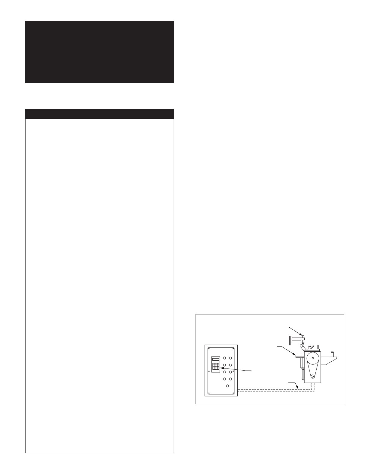
2. HOW AN EDGE SERVO
FEED OPERATES
The Edge Servo Roll Feed consists of:
2.1 MECHANICAL ASSEMBLY
(Refer to Figure 1)
1) Adjustment/Mounting bracket
2) Feeder
3) Motor
4) Mechanical pilot release actuator
2.2 ELECTRICAL CONTROL
ENCLOSURE ASSEMBLY
(Refer to Figure 1)
1) Control switches/buttons
2) Power supply, 120 VAC (for controls)
3) Motor/Axis control module
(inside electrical enclosure)
4) Data entry terminal
5) Cabling
5.1 PRIORITY MODE ............................ 7
5.2 SET-UP MODE ................................. 7
5.3 AUTO/MANUAL MODE .................... 7
5.4 LOADING THE FEED ....................... 8
5.5 RUNNING THE FEED ....................... 8
6. TROUBLESHOOTING GUIDE ..............11
6.1 PRO-200 MOTION
CONTROL CARD ERRORS ............12
6.2 DRIVE MODULE DIAGNOSTICS ....13
7. MAINTENANCE ....................................13
8. ROLL FEED PARTS LIST
AND DIAGRAM ....................................14
WARNING .................................................... 16
SAFETY PROGRAM ....................................16
WARRANTY .................................................16
CONTROL
ENCLOSURE
Figure 1.
MECHANICAL PILOT
RELEASE ACTUATOR
ADJUSTABLE
MOUNTING
BRACKET
DATA
TERMINAL
CABLES
DRAWING 17415
The introduction of servomotor technology to the
press roll feed has pushed the limits of accuracy,
adjustability, and performance to levels previously
unattainable.
2
Page 3

Each revolution of the servo motor produces 8000
encoder pulses. Every 2.909 revolutions of the
servo motor shaft produce 1 revolution of the feed
rollers. The circumference of the lower roll is
approximately 11.142 inches (on the SRF-125).
When a new feed pitch is entered into the system,
the built in computer calculates the correct
number of electronic "pulses" it must receive from
the motor mounted encoder in order to rotate the
feed rolls the correct distance.
Example: If a feed pitch/length of 11.142 inches is
entered into the feeder, this will result in exactly one
revolution of the feed rolls. The motor will accelerate and turn 2.909 turns. This will produce (2.909
x 8000 = 23,272) pulses of the encoder. The feeder
will decelerate and stop when 23,272 pulses are
detected. The feeder is now on position. The end
result is an accurately positioned strip exactly
11.142 inchs from its starting point. This entire
process happens in milliseconds.
having other equipment share the same circuit as the
feeder.) The inputs and outputs to your press control
(i.e. Emergency Stop, Feed Advance Cam Contact, Pilot
Release Cam Contact, Continue Cam Contact, End
of Strip Input) must also be connected for proper
operation. The motor connects by factory installed
"Amphenol" (Military Specifications) Quick connectors.
3.3 ELECTRICAL CONNECTIONS
For more detailed wiring information, refer to
Electrical Schematic A-17557-01 for 115 VAC and
Electrical Schematic A-17557-02 for 230 VAC.
NOTE:
All connections should be made in accordance
with National Electrical Code (NEC)
requirements and must comply with all local
ordinances.
3. INSTALLING YOUR EDGE
SERVO FEED
3.1 MECHANICAL INSTALLATION
The Edge Servo Roll Feed is supplied with an
adjustable mounting bracket. The feed should be
securely mounted to the press frame. (A transition
bracket is sometimes required in certain
applications). The feed should be centered, square,
and perpendicular to the pass line of the press.
It should be mounted at a height that will
accommodate the appropriate die sets. The feed
has a pass line height adjustment of ±1.2 inches
(Note: The centerline of the Feeder is NOT the
centerline of the rolls.) Refer to Figure 2 on
Page 4 for dimensioning.
The feeder may be used to push or pull strip stock
through the die.
If pilot locating pins are used in your die sets, the
optional mechanical roll release bracket should be
attached to the press ram. It must be mounted in
such a way as to provide roll release at the proper
time and be adjustable for different die sets.
If the optional electro-pneumatic piloting is
used, another cam switch will be necessary for
controlling feed roll opening and closing.
3.2 ELECTRICAL INSTALLATION
The Edge Servo Roll Feed has been designed to
make electrical connections quickly and easily.
Simply connect the power plug to a "clean" 120
VAC single phase 15 ampere source. (Note: Avoid
NOTE:
A word about electrical “noise”. Most pressroom
environments contain considerable electrical noise.
It is emitted from electro-mechanical press relays,
contacts, and solenoids. While The Edge Servo
Roll Feed has been designed to minimize
"self generated" electrical noise, it is difficult to
provide protection for all applications. If erratic
system behavior is experienced, then the source
of the "noise" must be suppressed with either a
resistive/capacitive type of suppressor on AC
coils, or "Avalanche" type diodes on DC coils.
NOTE:
The Edge Servo Roll Feed is fully protected
by line fuses. If it becomes necessary to replace
the fuses, use only exact equivalent fuse types to
prevent serious damage to the system.
NOTE:
The electrical control enclosure is supplied with
a stand/support which may be placed in any
convenient location. The enclosure may also be
mounted in any fixed location as long as the
cabling is adequate to reach the feed. It is not
recommended that the electrical enclosure be
mounted directly to the press. The vibrations
caused by the punch press can result In
damage to the control system.
3
Page 4
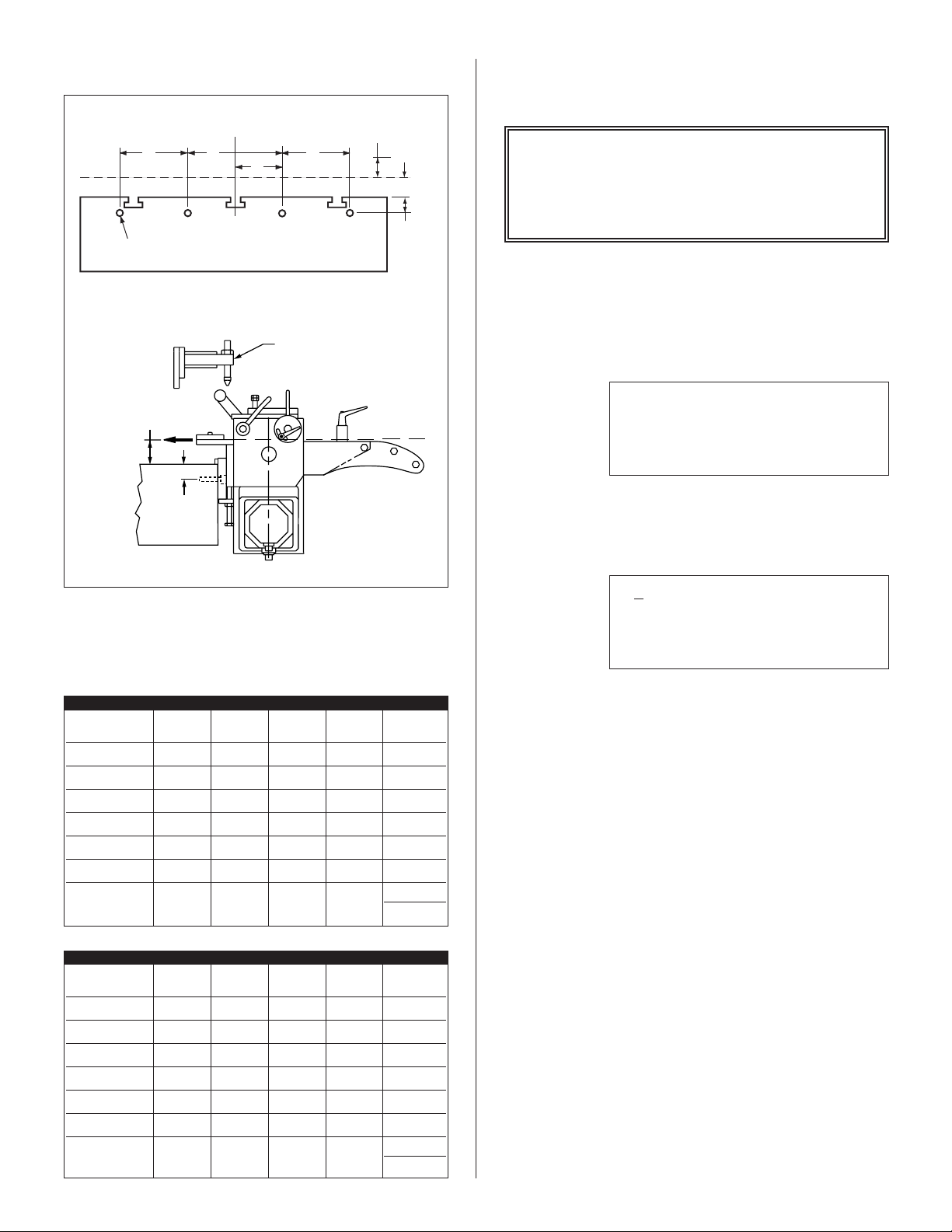
3.4 EDGE MOUNTING HOLES
4. PROGRAMMING THE EDGE
SERVO FEED SYSTEM
D
TAP X 1”(25mm) DEEP
TYPICAL MOUNTING ON GAP FRAME PRESS
E REF
PASS LINE
BOLSTER
CENTER LINE OF RAM
C
B
A REF
D
PASS LINE
BOLSTER
ADJUSTABLE
CAM BAR
DRAWING 17147-03
PASS LINE
ADJUSTMENT
E
A
IMPORTANT !
Before turning the system on for the first time,
verify that the main input voltage is correct
(120 VAC single phase) and inspect all
connections for tightness, shorts, etc.
STEP #1:
Press the amber ‘POWER ON’ push-button. The
button will illuminate and the data input display
will be visible:
P/A INDUSTRIES
☞
SERVO ROLL FEED
VERSION 1.00
HIT KEY TO CONT__
STEP #2:
Press any key on the terminal, the display will show:
Figure 2.
EDGE MOUNTING HOLES
for drawing 17147-03
INCHES
SRF-400/
DIMENSION SRF-100 SRF-125 SRF-200 SRF-300 500/600
A 1.18 1.97 1.97 1.97 1.97
B 1.97 3.15 3.94 3.94 3.94
C 3.94 6.30 7.87 7.87 7.87
D ––––5.91
TAP M14 M16 M16 M16 M16
E MIN. 2.2 2.4 2.4 2.4 2.4
PASS LINE +2 +2.4 +2.4 +2.4 +2.4
ADJUSTMENT -0.0 -0.0 -0.0 -0.0 -0.0
METRIC
SRF-400/
DIMENSION SRF-100 SRF-125 SRF-200 SRF-300 500/600
A 3050505050
B 50 80 100 100 100
C 100 160 200 200 200
D ––––150
TAP M14 M16 M16 M16 M16
E MIN. 55 60 60 60 60
PASS LINE +50 +60 +60 +60 +60
ADJUSTMENT -00.0 -00.0 -00.0 -00.0 -00.0
☞
LENGTH 00008.000
COUNT 100000
SPEED 0062/SEC
STEP #3:
The ‘POWER ON’ push-button has a ‘FAULT
RESET’ function built into the button. The feed
may now be jogged forward by pressing the ‘
FORWARD
pressing the ‘
’ button, or jogged in reverse by
JOG REVERSE’ button.
JOG
The Edge Servo Roll Feed has six viewable
screens. Only the first operator screen (shown
above) will be operator editable/programmable.
This screen displays the length, count, and speed
parameters. These parameters may only be changed
while the program is stopped (indicated by lack
of ‘
CYCLE START’ or set up light). The other
viewable screens are shown on the following page.
These five other screens will be viewable at all times,
but are "locked" out of programming via run/prog
switch located on the electrical panel inside the
electrical enclosure. The factory set parameter values
for the Edge Servo Roll Feed are printed on the
operator panel below the operator terminal.
4
Page 5

These parameters are set from the factory for
average feeding applications and they seldom
require any changes. The five screens and a brief
explanation of the parameters are described below:
• LENGTH: Distance in inches (or millimeters) of
the feed length. Maximum value of 4015 inches.
CNTS/UNIT: This is the encoder scaling
parameter used to define the number encoder
counts/inch (or counts/millimeter).
• TIME BASE: Time scaling parameter for various
parameters. This is always set to ‘
entering ‘
0’.
/SEC’ by
• COUNT: The number of pieces required to run
in the batch. Maximum value of 999,999 pieces.
• SPEED: The maximum velocity of the material
in inches/second (or millimeters/second).
Maximum value of 100 inches/second.
ACCEL 000402/SEC^2
☞
• ACCEL: The rate of acceleration in
inches/second
Maximum value of 1000 inches/second
• DWELL: The time delay, which controls the ‘ON’
duration of the cut output relay. The dwell is
used when the press or shear, lacks a continue
Bottom Dead Center (BDC) switch and the cycle
can be controlled by the dwell parameter.
• DBNC: This is the debounce parameter, which
is used to ignore contact bounce on the feed
signals.
☞
• PRIORITY: This parameter selects whether the
feeder indexes before the press starts ‘
(Feed-Before-Press), or the press starts before
the feeder indexes ‘
Entering a ‘
FBP’ mode.
‘
• BACKLIGHT: This turns on the backlight in the
display which enhances the viewing.
☞
DWELL 00.00
DBNC 1 X 3.75MS
2
(or millimeters/second2).
2
.
CNTS/UNIT 2089
TIME BASE /SEC
JOG SPEED 5%
DIRECTION CCW
FBP’
PBF’ (Press-Before-Feed).
0’ selects ‘PBF’ mode or a ‘1’ selects
PRIORITY PBF
BACKLIGHT ON
• JOG SPEED: The rate of jogging speed in
percent of the ‘
between 1 - 5%.
• DIRECTION: This parameter controls the
direction of positive motor rotation. 0 = CCW,
and 1 = CW.
☞
• KP: Proportional gain parameter for the motion
control. It controls the transitions between the
starting and stopping of the rolls. A lower value
provides a smoother (slower) transition.
• KD: This parameter is not used.
• KFF: Velocity feed forward gain. This is used to
reduce following error of the system.
• AUTO OFFSET: This parameter turns the
automatic offset on. Turn this feature on by
entering ‘
☞
• INPOSN: In-position parameter is a tolerance
window around the final position. This is used to
verify the feed index accuracy is within acceptable
limits before continuing onto the next function.
• FELim: Following error limit. FELim is the
maximum allowed position error. When this limit
is exceeded for the amount of time specified by
the FETime, the control will execute an
emergency stop.
SPEED’ parameter. Normally set
KP 0.56
KD 0.00
KFF 0.50
AUTO OFFSET ON
1’.
INPOSN 000.0200
FELIM 5.000
FETIM 0.500
SYSTEM RESET
•
5
Page 6

• FETime: Following error time. FETime is the
maximum amount of time that the following error
limit may be exceeded before executing an
emergency stop.
4.2 PROGRAM A NEW
BATCH COUNT
STEP #1
• SYSTEM RESET: This function clears all
parameters to the factory default conditions. No
program may be running,
(press and hold the ‘
the ‘
PROG/RUN’ switch must be set to ‘PROG’
position. Pressing ‘
SYSTEM RESET line will result in a confirmation
screen being displayed. Pressing ‘
time will reset the parameters to the factory
default values and the power-up screen will be
displayed. Pressing any other key than ‘
result in aborting the system reset.
1’ while the cursor is on the
RESET must be active
POWER ON’ button), and
1’ a second
1’ will
4.1 PROGRAM A NEW FEED
LENGTH, COUNT, SPEED
To program a new feed pitch/length the program
must be stopped. This may be done by pressing the
‘
POWER ON’ or the ‘CYCLE STOP’ button
(if the press is running). Press the ‘
button to view the following screen:
OPERATOR’
Position the ‘UNDERLINE’ type cursor under
OUNT. Use the ◗ key.
C
☞
STEP #2
Enter a new desired batch count. For instance....
1000 pieces. Press the ‘
buttons. The control takes a moment to clear the
existing batch count setting in memory, and then
“memorizes” the new value. Enter a value of ‘0’ to
disable the batch counter. The display should now
show:
☞
LENGTH 00001.253
C
OUNT 100000
SPEED 0062/SEC
1’, ‘0’, ‘0’, ‘0’, and ‘ENTER’
LENGTH 00001.253
C
OUNT 1000
SPEED 0062/SEC
LENGTH 00008.000
☞
STEP #1:
The ‘UNDERLINE’ type cursor is located under
the length display whenever this screen is called up.
This indicates that this entry is capable of being
modified.
STEP #2:
Enter a new feed length; for instance...1.253 inches.
Press the ‘
press the ‘
‘
ENTER’ key. The control will now take a moment
to clear the existing length value in its memory and
then "memorize" the new setting. The display
should now show the new feed length setting. The
maximum feed length is limited to 8,388,608
encoder counts or 4,015 inches.
1’ key, press the ‘.’ Key, press the ‘2’ key,
5’ key, press the ‘3’ key, and press the
COUNT 100000
SPEED 0062/SEC
4.3 PROGRAM A NEW SPEED
FOR THE FEED
STEP#1:
Position the ‘UNDERLINE
S
PEED with the ◗ key.
☞
STEP #2:
Enter a new speed value, 100 inches per second
is the maximum speed setting. 1 inch per second is
the minimum speed setting.
LENGTH 00001.253
COUNT 001000
S
PEED 0062/SEC
’ type cursor under
☞
LENGTH 00001.253
COUNT 100000
SPEED 0062/SEC
We will use 50/inches per second as our
example... Press the ‘
The control clears the existing value and inserts
50/seconds into its memory.
6
5’, ‘0’, and ‘ENTER’ buttons.
Page 7

The display should now show the new setting:
LENGTH 00001.253
☞
COUNT 001000
S
PEED 0050/SEC
These (3) parameters may be changed when the
running batch is stopped. All other feeder
parameters are locked out of the editing mode via
‘
RUN/PROGRAM’ switch located inside the
electrical enclosure on the panel.
5. OPERATING THE FEED
NOTE:
It is very important to remember that the motor
on the Edge Servo Roll Feed is only for feeding
material. It is not intended to be the power
source for a pull-through straightening device,
or the like. An adequate free loop must be
provided at all times. This will assure consistent
and accurate feeding.
5.1 PRIORITY MODE
The Edge Servo Roll Feed has (2) modes
of automatic cycle starting. The Operator can
choose between ‘
and ‘
FEED-BEFORE-PRESS’ (FBP) operating
PRESS-BEFORE-FEED’ (PBF)
mode.
When ‘
START
feeder causes the ‘
PBF’ mode is selected and the ‘CYCLE
’ button is pressed on the control panel, the
AUTO’ and ‘PERMIT PRESS’
relays to turn on thus enabling the start of
continuous cycling on the press.
When ‘
FBP’ is selected and the ‘CYCLE START’
button is pressed on the feed control, the material/
strip will be fed forward the programmed pitch
before the press is started. The Operator may verify
that the strip is in position before starting the press.
The Edge Servo Roll Feed will now follow the
press until it is stopped by the Operator, counter,
emergency stop, or feed error.
5.2 SET-UP MODE
‘SET-UP MODE’ is used primarily during the threading
of the strip through the die. This mode allows the
‘
JOG-TO-FEED’ Length operations to be performed.
While in ‘SET-UP MODE’, the strip may be moved
using the ‘
the ‘
JOG FORWARD’ operator button. If
JOG FORWARD’ is stopped before the ‘FEED
LENGTH’ is reached, then either the ‘JOG FORWARD
work. The ‘
strip to go backwards beyond the initial ‘
LENGTH’
’, or ‘JOG REVERSE’ operator buttons will
JOG REVERSE’ will not allow the
FEED
starting point. The ‘JOG REVERSE’
operator button will function until the end of the
‘
FEED LENGTH’ is reached.
During ‘
display will show ‘
‘
FEED LENGTH’ is reached, the jog buttons become
SET-UP MODE’, the bottom line on the
WAITING FOR JOG’. When the
inactive and the message on the display will show
‘
WAITING FOR JOG’. The jog buttons will not
become active again until after the press has made a
cycle.
5.3 AUTO/MANUAL MODE
‘AUTO MODE’ is used for production running of
the Edge Servo Roll Feed. When ‘
via the 2-position selector switch, the control is put
into ‘
MANUAL MODE’ until the ‘CYCLE START’
button is pressed. During ‘
MANUAL MODE’, the
feeder may be jogged infinitely in either direction.
After the ‘
CYCLE START’ button is pushed, the jog
buttons are inactive, and the feeding of the strip
follows the cam signals from the press. During
‘
AUTO MODE’, the control keeps check on
synchronization of the feeder and press. If the
Feeder does not complete the index within the feed
cam window, the message ‘
SYNC FAULT’ displays.
The Edge Servo Roll Feed has (2) modes of
automatic cycling. The feeder can operate with
‘
SINGLE STROKE’ or ‘CONTINUOUS PRESS
MODE
’. The mode is selected through an input
to the feed controller. The press single
‘
STROKE/CONTINUOUS MODE’ switch should be
interfaced to this input for proper operation.
During ‘
‘
PERMIT PRESS’ output relay is activated upon
SINGLE STROKE MODE’ operation, the
the completion of each feed index. The ‘
PRESS OUTPUT RELAY
’ remains active until the
continue cam signal turns on. The ‘
PRESS OUTPUT RELAY
’ may be used to signal
the press when to initiate the single stroke cycle.
The automatic cycling of the press and feeder will
continue until the batch is completed, or the cycle is
stopped by the Operator, or an error occurs.
During ‘
CONTINUOUS PRESS MODE’, the
‘PERMIT PRESS OUTPUT RELAY’ turns on at the
beginning of the indexing. The ‘PERMIT PRESS
RELAY
’ remains active until the automatic cycling
is stopped by either ‘CYCLE STOP’, ‘BATCH
COMPLETE
’, ‘SYNC FAULT’, or any other drive
AUTO’ is selected
PERMIT
PERMIT
7
Page 8

related error. Under ‘CYCLE STOP’ or ‘BATCH
COMPLETE
’ stopping, the output will turn off at
the beginning of the ‘FEED CAM SIGNAL’. This
should allow the press to stop near the top of the
stroke. Under ‘SYNC FAULT’ or other drive fault
conditions, the ‘PERMIT PRESS RELAY’ will turn
off immediately upon detection of the error.
5.4 LOADING THE FEED
8. Jog the press down slowly observing when the
longest pilot would engage the pilot hole in the
material if the material were there. (Refer to
Figure 4.) Note the press positional readout and
put this setting into your Programmable Limit
Switch (PLS) for the ‘PILOT RELEASE TURN ON’
setting. The ‘PILOT RELEASE TURN OFF’ setting
should be 180. (See Figure 5.)
PILOT PIN
ADJUST CAM
WITH MAT’L. IN
FEEDER. SET
FOR MINIMAL
PLAY
IN PILOT
LEVER
PILOT
LEVER
Figure 3.
ROLL RELEASE LEVER
MATERIAL THICKNESS ADJUSTMENT CAM
ADJUSTABLE
LOCK
SCREW
DRAWING 17415-02
Use the following steps to load the feeder:
(Refer to Figure 3)
1. Record the present settings of the feed advance
cam, continue cam, and pilot release cam into a job
set-up record sheet for future reference to the job
(see Programmable Limit Switch Job Set-Up Sheet).
2. Open the feed rolls by pulling on the Roll
Release Lever. Insert the material through the feed
rolls and close the feed rolls by releasing the Roll
Release Lever.
STRIP
Figure 4. PILOT PIN
9. Continue to jog the press slowly until the
longest pilot just comes above the material. Note
the press positional readout and put this setting into
your PLS for the ‘FEED ADVANCE TURN ON’
setting. Set the ‘FEED ADVANCE TURN OFF’
point approximately 30 degrees less than the pilot
release turn on point. (See Figure 5.)
10. Set the continue cam to turn on at 180 degrees
and to turn off at 200 degrees. This setting should
never need changing. (See Figure 5.)
5.5 RUNNING THE FEED
3. Adjust for the material thickness using the
Material Thickness Adjustment Cam and Adjustable
Lock Screw. Refer to the figure above for proper
setting.
4. Adjust the roll clamping force by pre-loading
the two die springs located on top of the feed
housing. Normal setting for the roll force spring
pre-load is two full turns clockwise from finger
tight. Be sure to use the jam nut to lock the
setting.
5. Using the ‘
JOG FORWARD’ button on the jog
pendant, advance the material up to the entrance of
the die (but not too far, where the punches would
pierce the material).
6. Check the vertical alignment of the strip. If
necessary, adjust the pass line of the feeder so that
the material is at the proper height.
7. Assuming that the press shut height and the
tool are set up properly, jog the press one or two
strokes without the feed working.
NOTE ABOUT CAMS:
The Feed Advance Cam (open tool): The
feed system uses this press cam for timing
the feeder to the press crankshaft. Although
no shafting or belts actually connect the
press to the feeder, the feed must be "told"
when it is safe to move the strip and when
the feed move must be completed.
• This “connection” is an electrical one,
and not a mechanical one. This gives the
operator/set-up personnel total flexibility in
deciding when the feed progression should
take place.
• Each die set can have a unique “feed
angle”. This “feed angle” is dependent
upon many variables; pilot and punch
length, press stroke, strip forming in the
die, etc.
8
Page 9

TYPICAL 180 DEGREE FEED ANGLE (FROM 260 DEGREES TO 80 DEGREES)
FEED ADVANCE CAM
180° FEED ANGLE
FEEDER STARTS FEEDING AT 260°
AND MUST BE IN POSITION AT 80°
WITH MECHANICAL PILOT RELEASE:
TDC
0°
FEED CAM “OFF”
FEED MUST BE
“IN POSITION”
80°
FEED CAM
“ON”
260°
ROLL CLOSING
ZONE;
FEED ROLLS
MUST FULLY CLOSE
IN THIS ZONE
TO PREVENT ROLL
SLIPPAGE AT START
OF FEEDING
235°
WORKING ANGLE
(PUNCHES IN STRIP)
(ROLLS RELEASED WITH
MECHANICAL RELEASE)
Figure 5. FEED ANGLE
200°
180°
BDC
CONTINUE CAM SIGNAL
CONTINUE CAM
CONTINUE CAM
ROLL OPENING
ZONE FOR
PILOT RELEASE
(PNEUMATIC OR
MECHANICAL)
“ON” AT 180°
“OFF” AT 200°
SAFETY ANGLE;
PRESS RAM MUST
STOP IN THIS ZONE
IN EVENT OF A
FEED ERROR
125°
DRAWING 17141-02
All the adjustments to the feed system and press
have now been made. The press is at Top Dead
Center (
TDC) and ready for automatic cycling.
Proceed by inching the press thru another stroke,
verifying that things are happening at the correct
time (pilot release, feed advance). If the system is
operating properly, you can make a few more “hits”,
check your parts, and then put the press into
continuous mode.
The Edge Servo Roll Feed will now follow the
press until it is stopped by the Operator, counter,
emergency stop, or feed error.
The display will show:
LENGTH 00001.253
COUNT 001000
SPEED 0050/SEC
BATCH RUNNING
The speed performance chart (Figure 6) is to be
used as a guide only. Actual feeder/press speeds
may vary depending on factors such as material
thickness, width, rigidity, surface finish, and line
payoff/straightener conditions.
9
Page 10

NOTES ABOUT
"POSSIBLE PROBLEM TOOLING":*
•
A tight die, one that is not square, or has other
tooling problems, will cause significant difficulty
and downtime. Accuracy in feeding is directly
related to how easily the feeder can position the
strip in the die. Binding, bad part ejection, or
sticking parts may cause the material to "jam" in
the die.
• The Edge Servo Roll Feed will "try" to overcome
the "jam-up" by applying more power to the rolls.
ONE OF FOUR OUTCOMES WILL RESULT:
•
The feed will continue to try to move the strip
(if the rolls do not slip) until the feed advance
cam opens. A Sync Fault Error will occur and
the press will be stopped by the feeder.
• The feed will apply more power to the rolls,
causing them to slip on the material. This
produces a "short-feed". In reality the feeder
Figure 6. SPEED PERFORMANCE CHART
did not "misfeed". The rolls were positioned
properly, the strip did not keep up, causing the
die to close and a miss-hit is produced.
• The feed applies more power to a thin strip,
causing the material to buckle somewhere
between the feed and the die set. The feeder
positioned the strip accurately, it just did not
occur in the die set.
• The feed tries to apply so much power to a heavy
strip in order to move it, that excessive current is
drawn by the servo drive. This results in the
drive shutting down to protect itself and in doing
so stops the press.
NOTE: The feed detected a problem and emergency-
stopped the press before the die closed. In using
the Edge Servo Roll Feed, you in fact have added
a "die protection" system to your tooling.
* A tooling problem is a problem caused by tooling
and not the Feeder itself.
VELOCITY = 100 In./Sec. ACCEL = 402 In./Sec
FEED (In.) FEED (mm) FEED TIME (Sec.) 90° 180° 270°
0.25 6.35 0.075 200 400 600
0.50 12.7 0.096 157 313 470
0.75 19.05 0.112 134 269 403
1.00 25.4 0.125 120 240 360
2.00 50.8 0.166 90 180 270
3.00 76.2 0.198 76 151 227
4.00 101.6 0.225 67 133 200
5.00 127 0.249 60 121 181
6.00 152.4 0.270 56 111 167
7.00 177.8 0.290 52 104 155
8.00 203.2 0.308 49 97 146
9.00 228.6 0.325 46 92 138
10.00 254 0.341 44 88 132
11.00 279.4 0.357 42 84 126
12.00 304.8 0.371 40 81 121
14.00 355.6 0.399 38 75 113
16.00 406.4 0.425 35 71 106
18.00 457.2 0.449 33 67 100
20.00 508 0.472 32 64 95
22.00 558.8 0.494 30 61 91
24.00 609.6 0.515 29 58 87
26.00 660.4 0.535 28 56 84
28.00 711.2 0.555 27 54 81
30.00 762 0.575 26 52 78
35.00 889 0.625 24 48 72
40.00 1016 0.675 22 44 67
45.00 1143 0.725 20 41 62
50.00 1270 0.775 19 39 58
55.00 1397 0.825 18 36 55
60.00 1524 0.875 17 34 51
2
FEED CAM WINDOW DEGREES
STROKES PER MINUTE
10
Page 11

6. TROUBLESHOOTING GUIDE
The chart that follows contains the most frequently encountered issues.
SYMPTOM CAUSE or REMEDY
No power indication when • Check main power supply for proper voltage.
‘POWER ON’ button is pressed
No display on power up • Check cabling connection between display and servo drive.
Feed will not jog • Check that the Feed is in manual mode. Move selector switch to ‘AUTO’;
• Check supply fuses and circuit breakers.
• Verify that the main disconnect switch is on.
• Verify that the E-Stop is not engaged (E-Stop Loop closed.)
• Check bulb in ‘POWER ON’ push button.
• Check 5 Volt logic supply LED on motion control card on right side
of Servo Drive/Amplifier under orange connectors.
• Check fuses in drive under right side cover.
press the ‘POWER ON’ push button to reset control.
• Check if the Feed is in ‘SET-UP’ mode. Waiting for press.
• Check if ‘IN POSITION’ indicator is off. Check parameters. Check drive
for Error Codes.
• Check ‘FAULT’ in display. i.e. ‘SERVO AMP FAULT’. Check drive for Error
Code. See Section 6.1
‘POWER ON’ indicator is lit, • Check that the ‘IN POSITION’ indicator is lit. If not, check parameters.
Feed will not operate.
Feed will not accept new feed • Check that the Selector switch is in Set-Up mode (running Set-Up program).
length or other parameters
Inaccurate feeding • Adjust rolls for correct material thickness; roll release lever must have
Feed runs backwards • Check for negative feed length, i.e. minus sign in length (–5.125).
• Check that the Error message is in the Display. If so, check error
description in Section 6.1
• Move selector switch to Auto, press ‘POWER ON’ button (E-Stop will show
in display), release ‘POWER ON’ button, try to jog feeder.
• Check that the Selector switch is in Auto mode and ‘CYCLE START’ has
been pressed (running Auto Program). Press ‘POWER ON’ push button
to reset.
• Check that the Run/Program toggle switch is in ‘RUN’ position; this will only
allow length, speed, and count to be changed. Set the Program Position;
then the Program position will allow any parameter to be changed.
small amount of play/wobble in it.
• Adjust spring pressure (Do not bottom springs. Catastrophic damage
can occur.)
• Confirm if rolls are slipping on strip. Remove oil from feed rolls, reduce
acceleration, check tool for binding/slugs, etc.
• Adjust Upstream Equipment if Upstream equipment not providing
adequate/consistent free loop.
• Check roll release for proper settings.
• Verify that direction parameter has been reset. Check CW or CCW
direction parameter.
Servo Amp Fault This is a generic display prompt indicating a fault on the Servo Amplifier.
• Look at the diagnostic display on the Servo Amplifier. The cause of the
fault can be determined by reading the Error Code.
• Refer to Sections 6.1 and 6.2. This fault condition can be caused by any
one of the errors in the lists.
• Check for Error Code first, then reset the Servo Amplifier by turning the
power off, waiting 10 seconds, then powering back on.
• Verify that the fault will not reset. Call the factory for assistance.
11
Page 12

Some errors encountered with the Edge Servo Roll Feed may be diagnosed by the motion controller. These
errors are typically displayed on the bottom line of the Operator Terminal Display. These errors are related to
improper motion of the servomotor. These errors are listed below. These errors may be reset by either pushing
‘
POWER ON’, which has a reset function, or by power-down and power-up.
6.1 PRO-200 MOTION CONTROL CARD ERRORS
SYMPTOM REMEDY
Encoder Feedback Error or • Simultaneous transitions on the ‘A’ and ‘B’ channels of the encoder were
Encoder Fault detected or one of the encoder signals is missing (possible broken wire).
Check Pilot Release settings for accuracy. Check Cabling.
Amplifier Fault Detected • The System Status Output from the Servo Amplifier went ‘OFF’, indicating
a problem with the Servo Amplifier. Try to reset fault by pressing
‘POWER ON’. Check Servo Amplifier for faults.
Excessive Follower Error • The follower error has exceeded the programmed maximum Follower
Error Limit (FEL) for the Programmed Follower Error time (FET).
• Check for loose or damaged encoder cable or motor cable.
• Check parameters for FEL and FET. Raise the values to see if error
diminishes.
• Check for excessively -speed setting. (I.e. above 72 Inches/Second)
• Check for binding in the tool. Check for mechanical binding or overload
caused by material or tooling.
Nonvolatile RAM Checksum Error • The process found a problem with the checksum of the parameters.
The most likely cause of this will be a power failure while entering new
data or electrical noise at power up/down.
• Loss of power while entering the parameters
• Electrical noise addection the control. Check all solenoids and relays for
surge suppression.
Parameter Error • A parameter was entered improperly. Review all parameters per legend
panel. Correct any deviant parameters.
Watchdog Time-out Fault • Check that the watchdog timer triggered, indicating that the
microprocessor was not operating properly or momentary power failure.
Frequently caused by ‘POWER OFF’ immediately followed by ‘POWER ON’
without waiting for ‘POWER ON’.
• Wait 10 seconds after power down before power on.
Limit Switch Hit • Check if the ‘FORWARD LIMIT’ or ‘REVERSE LIMIT’ switch has
been activated.
• Check Limit Switch for end of material at inlet of feeder.
• Check the inputs for 24 DC on the control.
If the problem you are having does not appear in the above chart, or does appear in the chart, and you have
questions about it, call the P/A Service Department for assistance. Please have your Model Number and Serial
Number ready. However, it is advisable to check the basics before calling to be sure the problem is not
something simple that may have been overlooked.
The servo drive module has built in diagnostics in the form of LED Indicators. See the following pages for more
detailed information.
12
Page 13

6.2 DRIVE MODULE DIAGNOSTICS
Use the following table for Drive Module Diagnostics.
LED Label LED Color Description
LOGIC P/S Green • ‘OFF’ = No incoming AC (Alternating Current) or if AC is present then
drive has internal power supply failure.
•‘ON’ = Power is present
• During ‘POWER DOWN’, LED should turn off within approximately
1 second If not, shunt regulator is not functioning. Replace Drive.
1,2,3 Red • ‘OFF’ = No Fault
1 Red • ‘ON’ = Motor Over Temperature. If motor not hot, check
cables, connections
2 Red • ‘ON’ = Short circuit Over Current or excessive Average Current.
Check cables, binding, loose belt, parameters, motor connections.
3 Red • ‘ON’ = Bus Over Voltage
1,2 Red • ‘ON’ = AC line loss
• Power circuit not providing adequate volts/amps
• Electrical noise on 120 VAC supply
2,3 Red • ‘ON’ = Drive Over Temperature. Check Amplifier for excessive heat,
hot enclosure
1,3 Red • ‘ON’ = Logic Supply Fault. Check fuses in Servo Amplifier
NOTE:
While the reset is engaged LED’s #2,3,4,will remain on and LED #1 will remain off.
7. MAINTENANCE
• The roll release system requires clean, dry
air supply.
The Edge Servo Roll Feed needs very little
maintenance to keep the system operating at its
optimum performance.
• Some bearings used on the feeder are fully sealed
and maintenance-free roller ball bearings. The
exceptions are provided with standard “zerk” type
• This precision equipment must be kept as clean
as possible. This is especially important if large
amounts of air suspended oil mists in combination
with “dirty metals” are used. The resulting abrasive
dust can attach itself to the feed rolls and other
surfaces, leading to premature wear on many
parts.
grease fittings. They should be lubricated with a
good grade of high pressure bearing grease. The
frequency of lubrication will depend on the overall
usage of the system. A small “shot” once a day is
a good starting point. The cluster gear set should
be coated with a small amount of open gear grease.
13
Page 14

• The main drive belt should be checked periodically
for tightness. It can be adjusted by loosening the
two fasteners on the motor adjuster plate, applying
downward pressure on the motor adapter plate,
and retightening. ERRATIC MOTOR
BEHAVIOR WILL BE EXPERIENCED IF THE
DRIVE BELT IS LOOSE!
• All fasteners should be checked for tightness at
regular intervals. The electrical system also requires
very little maintenance. Keep the enclosure clean
and replace any burned indicator bulbs. Do not
expose the electrical enclosure to constant high
temperatures. Possible system failure could result.
8. ROLL FEED PARTS LIST & DIAGRAM
• The Feeder’s electrical enclosure door is sealed
to prevent oil and contaminants from entering
inside. However, small gaps can be found around
some sealing surfaces and faceplates. It is a
good idea, therefore, to keep the console free of
stamping oils and fluids, which could "seep into"
the enclosure. Most often these oils are
carried by the operator’s hands or by air mist
lubrication etc.
• All of the above guidelines should be added to
your existing pressroom Preventive Maintenance
(PM) Program.
ITEM QTY DESCRIPTION
1 1 BEARING HOUSING - LEFT SIDE PLATE
2 1 BEARING HOUSING - RIGHT SIDE PLATE
3 1 PLATE- CASCADE MTG.
4 1 PLATE - FEED MTG.
5 1 PLATE - EXIT
6 1 PLATE - MATERIAL HOLD DOWN
7 1 BRACKET - UPPER ROLL, LEFT
8 1 BRACKET - UPPER ROLL, RIGHT
9 1 PLATE - UPPER ROLL
10 1 GUARD - ENTRY
11 1 ROLL - LOWER
12 2 DUST SHIELD - LOWER
13 1 SPACER - LOWER
14 2 BEARING - LOWER
15 1 GEAR - LOWER
16 1 ROLL - UPPER
17 2 DUST SHIELD - UPPER
18 2 RETAINING RING
19 2 BEARING - UPPER
20 1 GEAR - UPPER
21 1 SHAFT - THICKNESS ADJUSTMENT
22 1 LEVER - THICKNESS ADJUSTMENT
23 1 CAM ECCENTRIC BUSHING
24 1 BUSHING - TAPER LOCK - INNER
25 1 BUSHING - TAPER LOCK - OUTER
26 1 SHAFT - ROLL RELEASE
27 2 BEARING, NEEDLE
28 2 WEAR PAD
29 1 RELEASE LEVER - MANUAL
30 1 RELEASE LEVER - MECHANICAL
31 1 BEARING - ROLL RELEASE
32 1 SPACER - RELEASE BEARING
33 2 RETAINER, SPRING ROD
34 2 ROD, ROLL TENSION
ITEM QTY DESCRIPTION
35 2 SPRING, ROLL TENSION
36 1 SET SCREW M6 X 16
37 2 BRACKET - CASCADE
38 1 BLOCK - CASCADE MTG., LEFT
39 1 BLOCK - CASCADE MTG., RIGHT
40 1 PLATE - ENTRY
41 2 BAR - GUIDE ROLLER
42 2 CLAMP - GUIDE BAR
43 2 GUIDE ROLLER
44 4 SPACER - GUIDE ROLLER
45 2 NUT - T SLOT
46 3 ROLL - CASCADE, ENTRY
47 3 SHAFT - ROLL
48 10 BEARING - GUIDE & ENTRY ROLL
49 1 TRANSITION PLATE
50 1 ADJUSTMENT TAB
51 1 SCREW - HEX HD
52 1 NUT - HEX, JAM
53 1 KEY 22mm x 5mm x 110mm
54 2 KEY 22mm x 12mm x 40mm
55 1 STRIKER - RELEASE ACTUATOR
56 1 ARM - ADJUST
57 1 ARM - FIXED
58 1 BLOCK - MOUNTING
59 1 BRACKET - MOUNTING
60 1 NUT, STRIKER ADJUST
63 1 KEY 7mm SQ x 35mm
64 1 KEY 5mm SQ x 15mm
65 4 GREASE FITTING
67 4 NUT, M14, ROLL TENSION
68 1 COVER, FEED ROLLS – SRF-100
69 2 HANDLE, WIDTH GUIDE ADJUSTMENT
70 1 HANDLE, THICKNESS ADJUSTMENT
71 6 NUT, HEX
14
Page 15

EDGE MECHANICAL PARTS DIAGRAM 17135-01
DRAWING A17135-01
PNEUMATIC PILOT RELEASE
Item Description Part No.
1 Solenoid Valve 12039-62 (120V)
Solenoid Valve 12039-67 (220V)
Solenoid Valve 12039-68 (24VDC)
Solenoid Valve 12039-69 (24VAC)
2 Cylinder, SRF-100 12111-26
Cylinder, All Others 12111-27
3 Bracket 16730
4 Suppressor 16286-02 (120V)
4 Suppressor 16286-03 (220V)
4 Suppressor 16286-04 (24VDC & 24VAC)
15
Page 16

WARNING
This equipment offers various means of operating or
controlling machines. The operator must not be in or
near the point-of-operation of the machine, or the
operating parts of any equipment installed on the
machine, or bodily injury could result. The EMPLOYER
must post adequate warning signs onto the machine with
proper warnings for his machine and the specific
application to which the machine and equipment are
being applied.
Occupational Safety and Health Act (OSHA) Sections
1910.211, 1910.212, and 1910.217 contain installation
information on the distance between danger points and
point-of-operation guards and devices. No specific
references have been made to which paragraph
of OSHA 1910.211, 1910.212, 1910.217, or any other
applicable sections because the paragraphs may change
with each edition of the publication of OSHA
provisions.
All equipment manufactured by us is designed to meet
the construction standards of OSHA in effect at the
time of sale, but the EMPLOYER installs the equipment
so the EMPLOYER is responsible for installation, use,
application, training, and maintenance, as well as
adequate signs on the machine onto which this
equipment will be installed.
Remember, OSHA says that the EMPLOYER must use
operating methods designed to control or
eliminate hazards to operating personnel.
It shall be the responsibility of the EMPLOYER to
establish and follow a program of periodic and regular
inspections of his machine to insure that all their parts,
auxiliary equipment, and safeguards are in a safe
operating condition and adjustment. Each machine
should be inspected and tested no less than weekly to
determine the condition of the machine. Necessary
maintenance or repair of both shall be performed and
completed before the machine is operated. The
EMPLOYER shall maintain records of these inspections
and the maintenance work performed.
Our Company is not responsible to notify the user of
this equipment of future changes in State or Federal
laws, or construction standards.
SAFETY PROGRAM
Accident free operation will result from a well developed,
management sponsored and enforced safety program.
Of vital importance to any successful program is the
proper selection of guards and devices. However, there is
no safety device that will bring "automatic" safety to
your operation.
Of equal importance to this proper selection of the guard
and the device is the training of your personnel. Each
person must be trained as to the operation of the guard
or safety device, highlighting why they have been
provided on the equipment. Rules for safe operating
should be written and enforced at all times. A final
major concern of an effective safety program is regularly
scheduled inspection and maintenance of all of the
equipment.
To ensure continued safety at all times, top management,
line supervision, safety engineers and all employees must
assume their proper share of the responsibility in the
program. Only as a group, one that knows your own
operation and its problems, can you carry out an
effective safety program.
To assist you in the development of and continued use
of safety programs, many safety minded groups have
made guidelines available to you. However, you must
know when and how to apply these guidelines. The
manufacturer provides information to assist you in
properly adjusting and maintaining your equipment.
There is no shortcut to proper safety; therefore, it is
recommended that you comply with their
recommendations at all times.
WARRANTY
We warrant our new parts against defects under normal
use and service for a period of 12 months after date of
shipment. Our obligation under this warranty is limited
to replacing or repairing (at our option) the defective
part without charge, Freight On Board (FOB) our plant
in Bloomfield, Connecticut. The defective part must be
forwarded to our plant, freight prepaid, for our inspection
prior to replacement or repair. EXCEPT AS EXPRESSLY
PROVIDED HEREIN, THIS WARRANTY IS IN
LIEU OF ALL OTHER WARRANTIES, EXPRESS
OR IMPLIED, INCLUDING A WARRANTY OF
MERCHANTABILITY OR FITNESS FOR A
PARTICULAR PURPOSE. Furthermore, the seller does
not warrant or represent that the equipment complies
with the provisions of any law, particularly including the
Occupational Safety and Health Act of 1970, and
regulations promulgated thereunder. In no event shall we
be liable for special, indirect incidental or consequential
damages, however rising.
P/A INDUSTRIES INC. 522 Cottage Grove Road • Bloomfield, Connecticut 06002-3191 U.S.A.
Toll Free 1-800-243-8306 • Worldwide 1-860-243-8306 • Fax 1-860-242-4870
Website http://www.pa.com • E-Mail service@pa.com
FORM 1037 12-00
16
 Loading...