

Page 1

PRECISION
AIR FEED
®
INSTALLATION
& OPERATING
INSTRUCTION
MANUAL
Page 2

P/A INDUSTRIES INC.
OVER FORTY YEARS EXPERIENCE
Since 1954, P/A engineers have been designing
and building equipment for the Metalforming Industry.
Our commitment to provide innovative production
equipment of the highest quality is second to none.
CUP SEAL DESIGN
P/A is the only air feed manufacturer that provides
low maintenance, high-cycle life cup wiper seals on
the main cylinder. Every quality-built air cylinder uses
the same technology as P/A. Cup seals reduce
friction and heat which increases cycle life and
performance by a conservative factor of 50 times.
U.S. PATENTS
The leader in pneumatic press feed patents in the
world is unquestionably P/A Industries. Todays design
is covered by a combination of the following patents:
3,329,327; 3,462,056; 3,485,430; 3,561,657;
3,583,268; 3,561,309; 3,847,320; 4,051,987;
4,195,161; 4,310,114; 4,160,518; 4,076,161;
4,095,733; 4,140,261; 4,175,688; 4,290,541;
4,261,238; 4,277,997; 4,207,999; 4,267,950;
4,329,897; 4,351,462; 4,399,937; 4,444,346;
4,531,662; 4,619,390.
Other patents pending and foreign patents are not
included above.
Page 3
CONTENTS
P/A believes in providing the best production
performance air feed available anywhere in the world
today. To prove that we are the BEST, a serialized
Repair Certificate is
enclosed with each
air feed. This can
be used at any
time for a
“no-charge” repair.
Please keep this
valuable
Certificate with
your records
and return to
P/A with the
feed for our
FREE REPAIR
SERVICE.
AIR FEED FEATURES .................................................... 2
MOUNTING THE AIR FEED ........................................... 4
AIR POWER SUPPLY CONNECTION
TO THE FEED ............................................................ 5
FEED LUBRICATION ...................................................... 5
PRESS FEED TIMING .................................................... 6
AIR FEED SEQUENCE ...................................................7
CONTROLLING THE FEED
Mechanical Actuation .................................................. 8
Remote Pneumatic Actuation ..................................... 9
Remote Electric Actuation .........................................10
Repeater Control System .........................................11
FEED LENGTH ADJUSTMENT .................................... 11
MATERIAL ADJUSTMENT ............................................12
SPEED CONTROL ........................................................13
THREE PILOT RELEASE METHODS .......................... 14
FEEDING SHAPED MATERIAL .................................... 15
PROTECTIVE COVERS ...............................................15
MODEL AX PARTS LIST ...............................................16
MODEL AX EXPLODED VIEW ..................................... 17
MODELS CX, DX PARTS LIST ..................................... 18
MODELS CX, DX EXPLODED VIEW ........................... 19
MODELS FX, HX, LX PARTS LIST ...............................20
MODELS FX, HX, LX EXPLODED VIEW ..................... 21
ACTUATION METHODS ............................................... 22
PILOT RELEASE ACTUATION METHODS .................. 23
TROUBLE SHOOTING CHART .................................... 24
1
Page 4
AIR FEED FEATURES
FASTER SPEEDS
Our patented system sequences
high speed models up to 400 cycles
per minute at full two inch pitch.
VERSATILE
Coil stock can be fed in any direction
or angle at any time during the
machine cycle. A single feed can
push or pull through long or short
progressions. A variety of stock
widths and thicknesses can be fed at
different speeds and feed lengths.
Two or more strips can be
simultaneously fed by the same feed.
INEXPENSIVE
The cost of P/A feeds are 65% to 90%
less than conventional roll or slide
feeds. With savings like that you
should consider leaving the feed
permanently mounted on the tool
to decrease set up time and increase
productivity.
Surveys show that Contract Job
Shop Stampers prefer P/A air feeds
because they are the easiest and most
economical way to change from one
job to another.
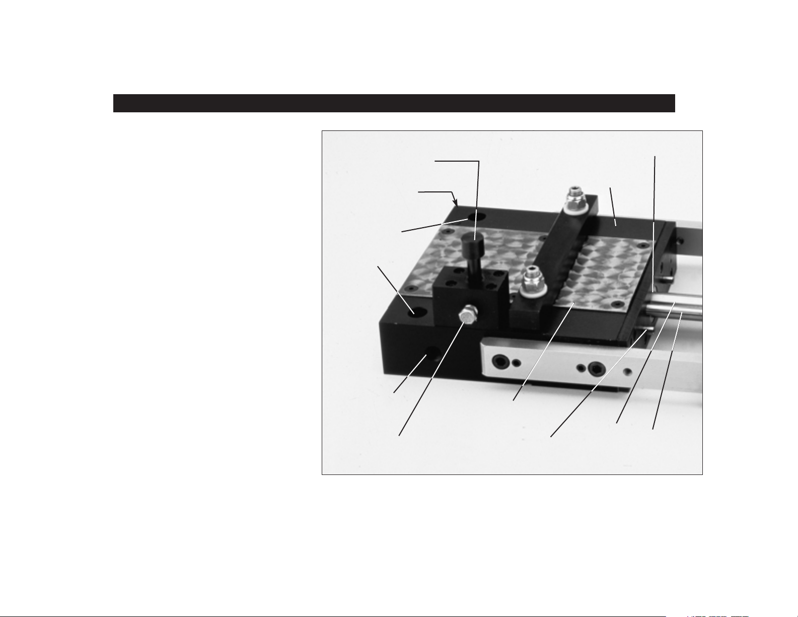
Actuating valve or optional
remote actuation controls feed
motion and clamp sequencing
Speed adjustment screw
controls feed head velocity
and material inertia
Two (or four) drilled
holes provide easy
mounting to die shoe,
bolster, or mounting
bracket
Oversized air inlet
eliminates air pressure
volume problems
Air silencers greatly
reduce noise to enhance
the operator’s environment
Modern Cup Wiper Seal (instead of “O” Rings) maintains
clean piston assembly and significantly increases cycle life
Body constructed of hard-coat
anodized, aircraft aluminum for weight
reduction and minimal wear characteristics
Replaceable steel wear
plates protect feed surface
from material edges
Two shock absorbers
automatically control feed
head and material inertia
Main piston
rod is hard
chrome plated
and ground
Twin
external air
tubes are
stainless steel.
2
Page 5
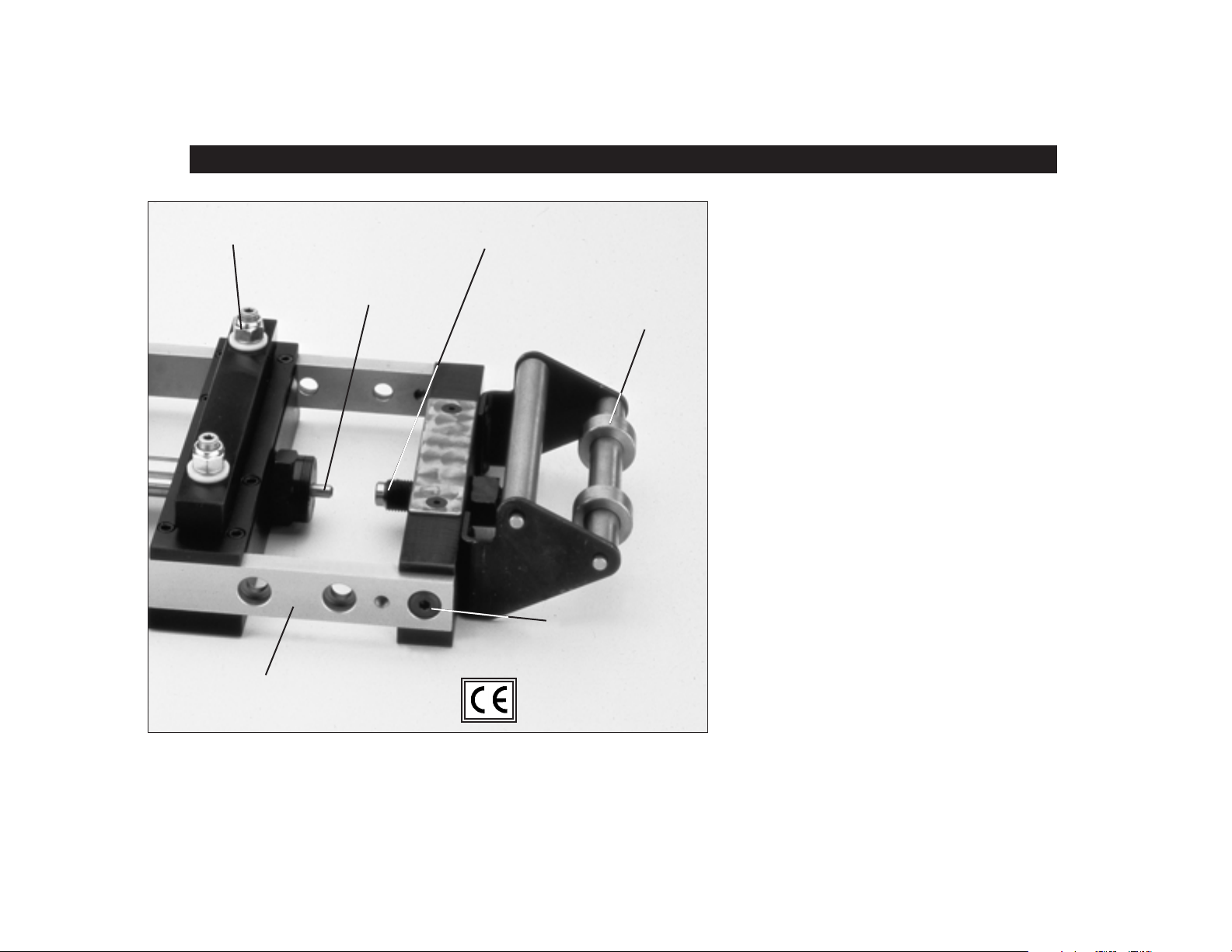
AIR FEED FEATURES
Nylock hex nut used in aircraft engines
to absorb vibration and eliminate loosening
Shock absorber stops
slamming and reduces noise
High strength, chrome plated, steel
guide rails maintain feed head alignment
throughout its stroke
Large adjusting screw and lock nut
provide vernier feed length control
Combination stock dampener and
adjustable guide rollers provide
vibration free material to the feed
Counterbored holes and
precision ground shoulder
screws provide coarse feed
length adjustment and secure
rigid alignment
SIMPLE INSTALLATION
Our feeds are extremely easy to mount.
Two (or four) mounting bolts and a single
air line connection are all that’s necessary.
A compact, clean design permits the P/A
Air Feed to be mounted right on the die set.
QUICK SET-UP
Adjustments are quick, simple and positive.
To change feed length, turn the adjustment
screw to the desired pitch between positive
stops and tighten the locknut.
PATENTED DESIGN
Technologically the BEST air feed on the
market today! U.S. Patent No. 4,444,346.
REPEATABILITY
Consistently holds ±.001" (.025mm) stroke
after stroke. The most precise press feed
available at a reasonable cost.
HANDLES VARIETY OF MATERIALS
Paper, plastic, foil, fabric, wire, tubing
...you name it and P/A will feed it. Highly
polished materials or extrusions, preformed
or irregularly shaped materials – all can
easily be adapted with special clamps.
3
Page 6
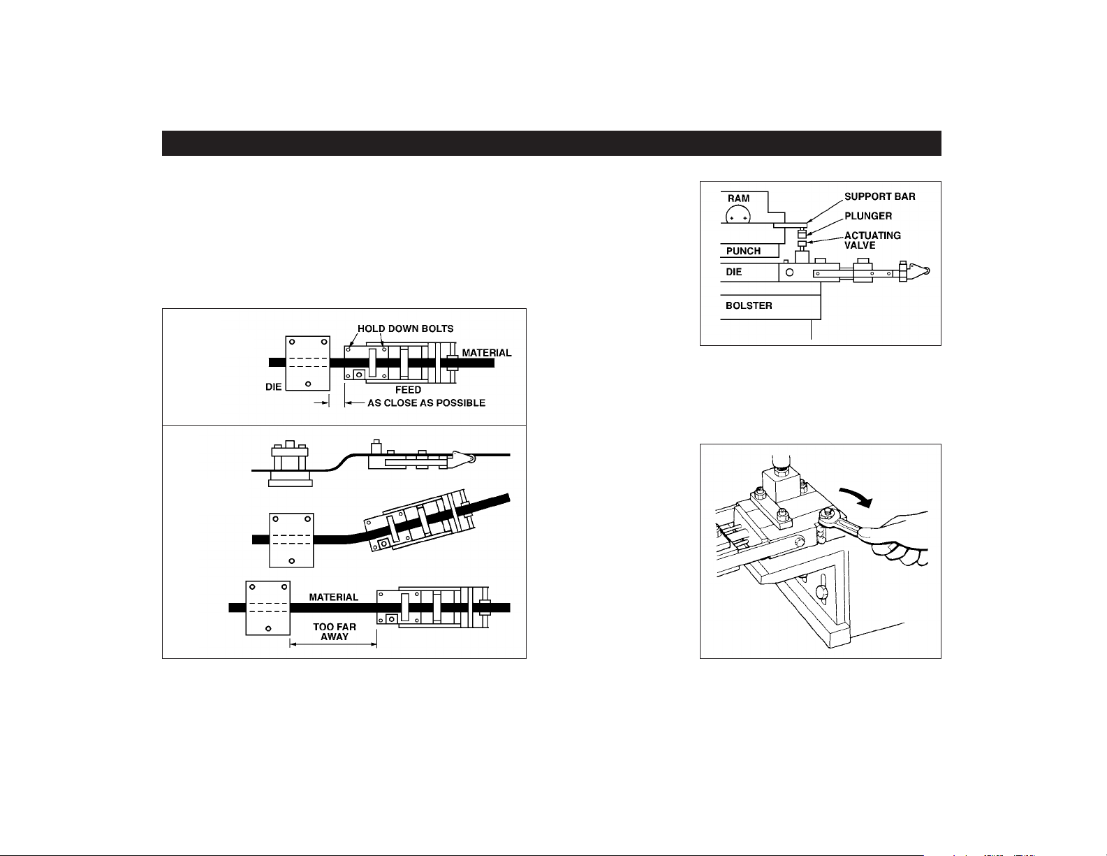
MOUNTING THE AIR FEED
Its compact design will allow this Feed to be installed
on the Die or Press Bolster, or on many types of
machines, at any angle, including upside down or
vertical. Use two (or four) minimal clearance HoldDown Bolts to solidly fasten the Feed as close to the
Work Station as possible. NEVER use ‘C’ clamps as
the Feed may move or shift position.
CORRECT
NOT
CORRECT
Mounting directly
on the Die is
recommended
for “Just-In-Time”
production and
to reduce set-up
time.
The top of the Feed Wear Plate should be level with
the lower Die Face and the front of the Feed square
and centered with the tool.
A mounting
bracket provides
easy vertical
adjustment for
tools with different
stock line
heights.
The Feed can be
moved from
press to press, or
die to die, in a
matter of minutes.
4
Page 7
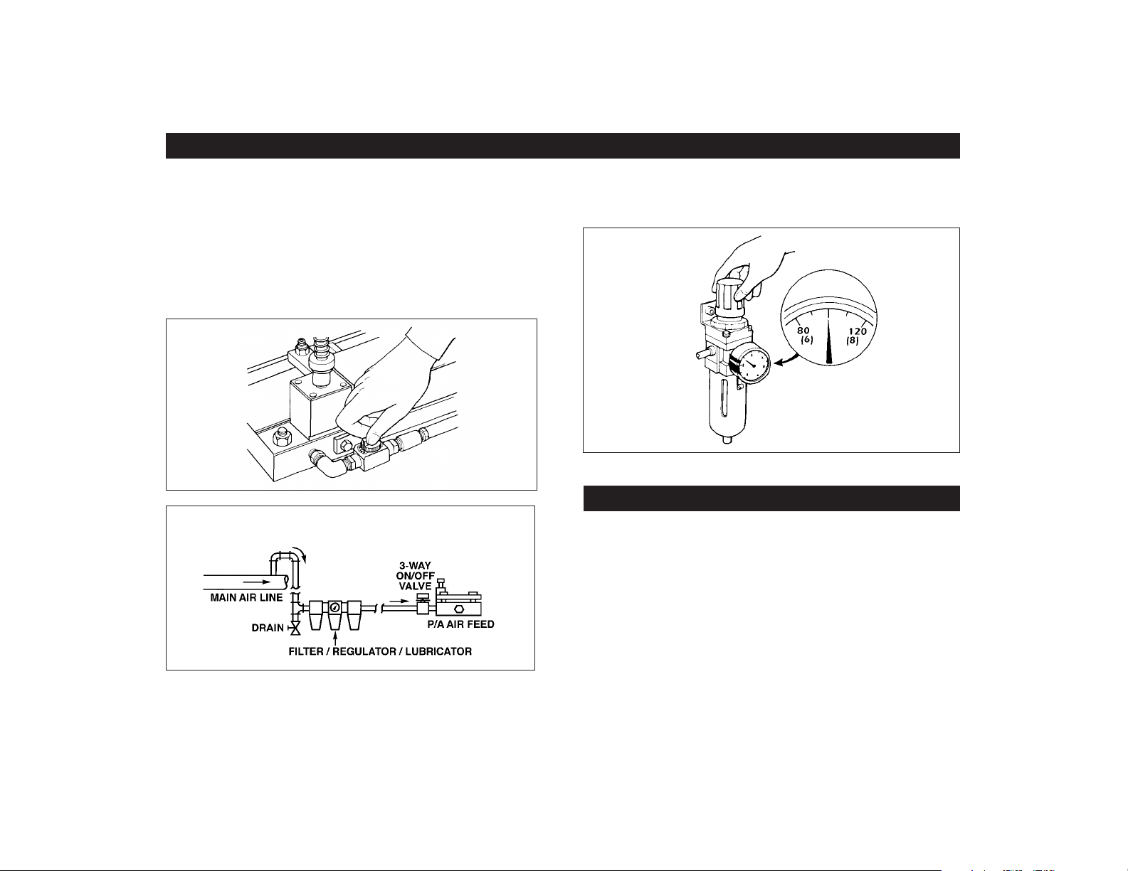
AIR POWER SUPPLY CONNECTION TO THE FEED
A single air line connection is all that is needed for
maximum power with minimum air consumption. We
strongly recommend that an oversized air hose be
connected to the Feed with a water separator type
filter and air line oiler.
The use of a 3-Way On/Off Exhaust Valve will make
minor adjustments and strip insertion easier.
RECOMMENDED AIR LINE CONNECTION
TO ELIMINATE MOISTURE AND PARTICLES FROM MAIN LINE
Set the Air Pressure Regulator between 80 and
120 PSI (6 to 8 Bar).
FEED LUBRICATION
Fill the air line lubricator with a good grade of
hydraulic cylinder oil, like Shell Tellus 32. Set for one
drop per minute to properly clean and lubricate all
internal parts.
NEVER use Spindle Oils, Motor Oils, Solvents,
WD-40, or Stock Lubricating Oils. Use of these types
of oils will cause Feed performance to deteriorate, as
well as premature wear.
5
Page 8
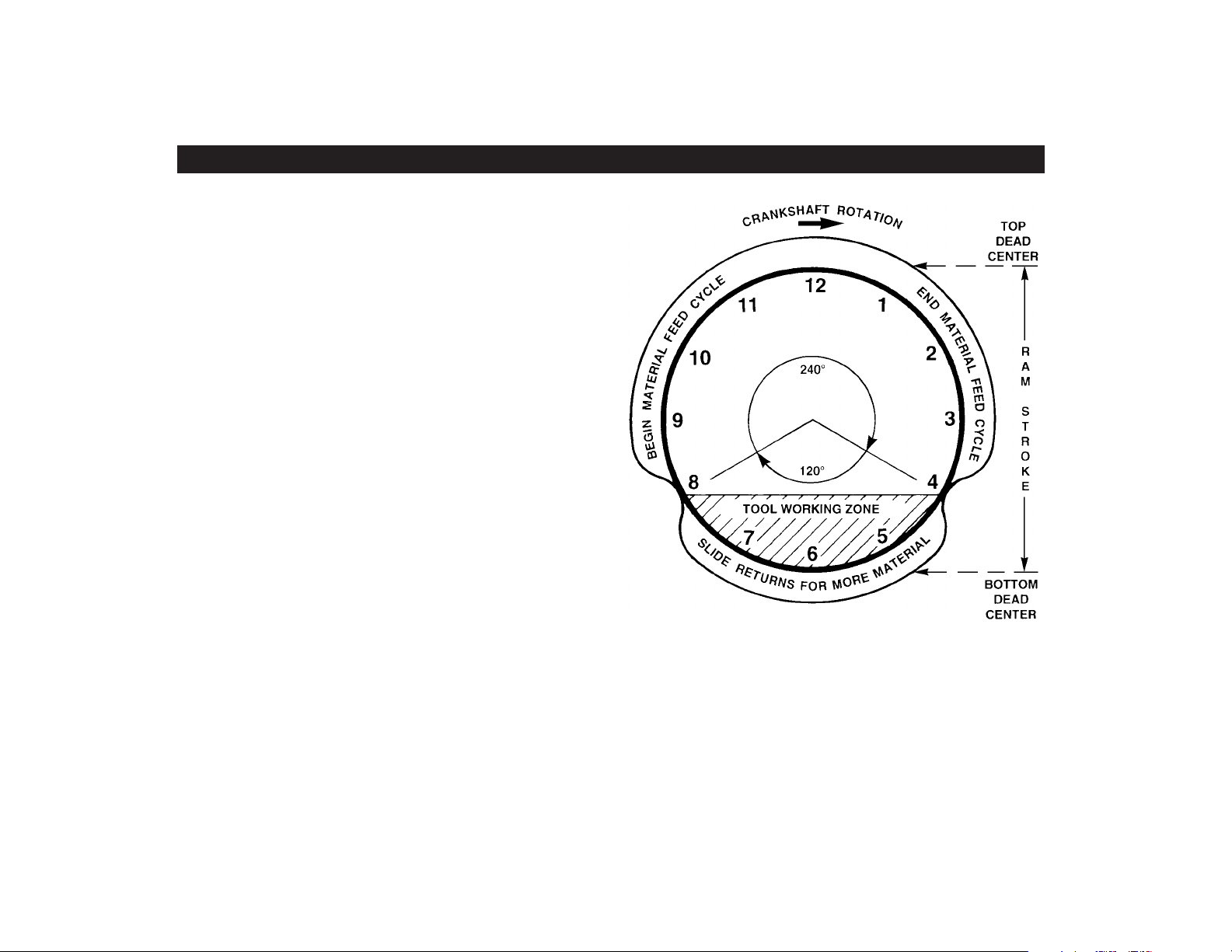
PRESS FEED TIMING
The Reciprocating Linear Motion of the Feed Slide must
be timed to the press crankshaft rotation for optimum
performance. The Actuating Valve’s vertical motion
controls the sequencing of the Stock Clamp, Feed
Clamp, and the Feed Slide.
To understand how the rotary crankshaft and linear
Feed Slide motion work together in a Press Feed Cycle,
it might be helpful to visualize a Clock Face. The
position “Top Dead Center” of the Ram Stroke would be
12 o’clock, half way down would be 3 o’clock, “Bottom
Dead Center” is 6 o’clock, and moving half way up
would be 9 o’clock.
The optimum Feed cycle requires two thirds of the
crankshaft rotation (240 degrees) to feed the material
into position. During the remaining 120 degrees, the
Feed Slide returns to the Stop Screw for more Material.
As soon as the Stamped Part has been ejected and the
Punches are clear of the Die (approximately 8 to 8:30
on the clock), the Feed Clamp will grip the Stock and
then the Feed Slide will begin moving towards the Feed
Body.
CAUTION: To properly complete a Feed Stroke, the
Feed Slide must have enough time to contact the Feed
Body before 4 o’clock and then return to the Stop Screw
before 8 o’clock during the 360 degree crankshaft rotation
otherwise erratic short feed progressions will occur.
6
Another method of controlling the Feed Timing is
to use the Remote Electric or Pneumatic Actuation
Systems to suit the Press and Part applications.
These methods require the same 240° feed and 120°
return timing cycle.
Page 9
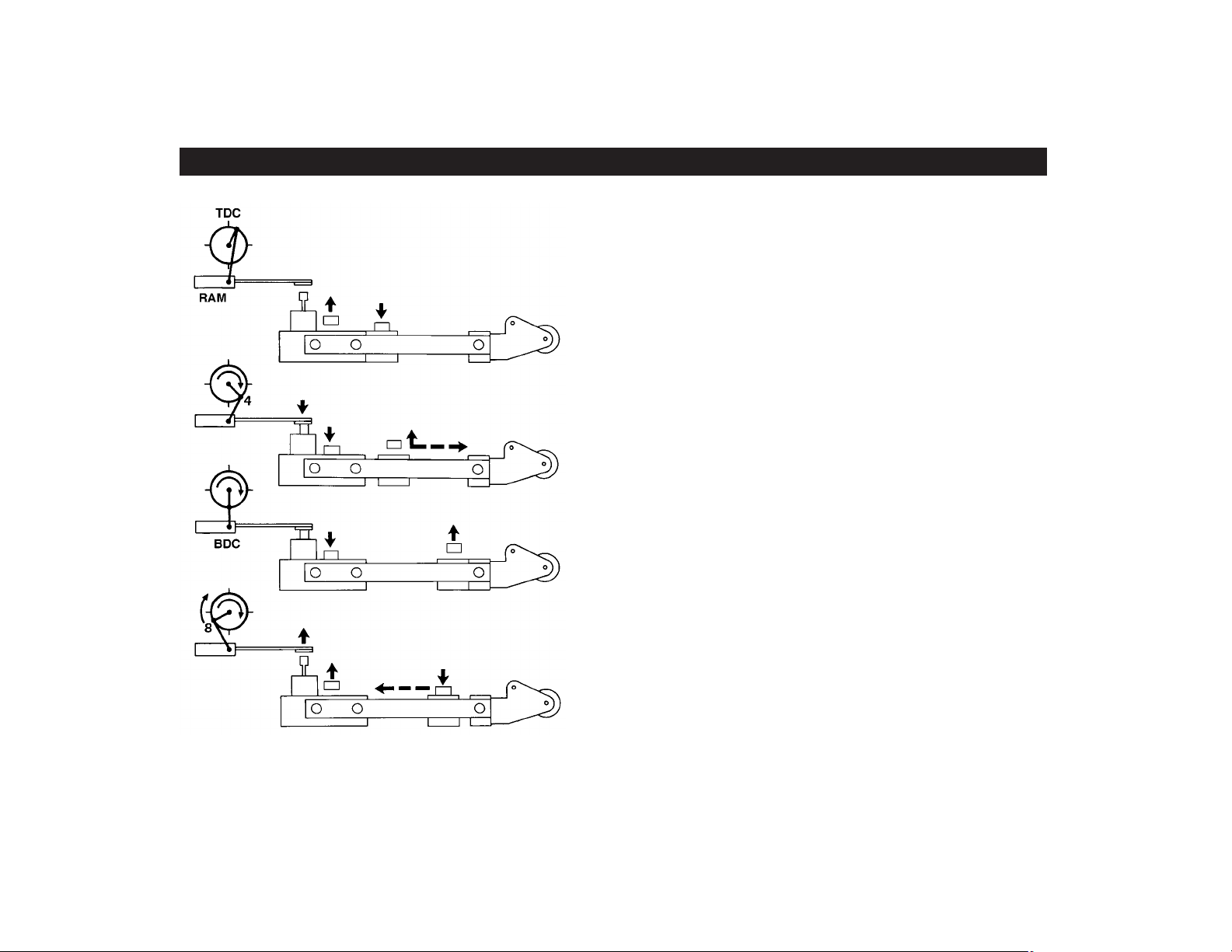
AIR FEED SEQUENCE
Actuating Valve up
•
Feed Slide forward
•
Stock Clamp open
•
Feed Clamp closed
•
Actuating Valve down
•
Stock Clamp closes
•
Feed Clamp opens
•
Feed Slide moves back
•
Feed Slide rests
•
against Stop Screw
Stock Clamp closed
•
Feed Clamp open
•
AT TOP OF
PRESS STROKE
AT BEGINNING OF
NON-FEED STROKE
AT END OF
NON-FEED STROKE
Actuating Valve up
•
Feed Clamp closes
•
Stock Clamp opens
•
Feed Slide moves forward
•
AT BEGINNING OF
FEED STROKE
7
Page 10

CONTROLLING THE FEED
MECHANICAL ACTUATION
Install a Support Bar with a Plunger on the upper Die
Block of the Tool or on the Press Ram. The vertical
Plunger should be threaded to allow vertical height
adjustments. The Plunger should contact the center
of the Feeder’s Actuating Valve Stem. After contact,
and during the first 1/4" (6mm) of downward Valve Stem
travel, nothing happens with the Feed Slide Control.
During the next 3/16" (5mm) of travel, the Mechanical
Actuation Valve opens causing the clamps to shift and
PRESS CRANKSHAFT
ROTATION
SUPPORT
BAR
RAM
RAM
MECHANICAL
ACTUATING
VALVE
PLUNGER
VALVE
STEM
AIR FEED
the non-feed stroke begins. The remaining downward stroke of the Valve Stem is over-travel.
When the Press Ram passes BDC and begins to
move upward, the Valve Stem reverses travel direction.
As the Plunger moves off the Valve Stem, the
Mechanical Actuation Valve closes causing the clamps
to shift and the Feed Slide to begin the feed stroke.
Installing a Spring on the Plunger to contact the
Actuating Valve Stem will result in a more desirable
Feed Cycle for Presses with long strokes.
CAUTION! Excess over-travel will damage the Feed
TDCTDC
RAM
SPRING
COMPRESSED
8
Page 11

CONTROLLING THE FEED
REMOTE PNEUMATIC ACTUATION
By removing the Mechanical Actuating Valve
Assembly, the timing control of the feed cycle can be
changed by installing the optional Piston Operated
Valve (POV).
LINEAR CAM OPERATION ROTARY CAM OPERATION
1/4” (6MM) POLYFLO TUBING LINEAR CAM/BRACKET
AIR CONNECTION FROM PISTON
OPERATED VALVE TO COMMON
(“CYL”) PORT OF SPOOL VALVE
MALE CONNECTOR AT
VALVE PILOT AIR PORT
PISTON OPERATED VALVE
CONNECTION
3-WAY ON/OFF
SELECTOR VALVE
RECOMMENDED
TEE FITTING AT AIR INLET
AIR SUPPLY
The Feed Cycle is then controlled by a cam operated 3-Way Spool Valve and a Linear Cam mounted
on the Press Ram, or by a Rotary Cam mounted on
the crankshaft.
CAM OPERATED 3-WAY
SPOOL VALVE
AIR CONNECTION
FROM TEE TO NORMALLY
CLOSED (“IN”)
9
Page 12

CONTROLLING THE FEED
REMOTE ELECTRIC ACTUATION
To control the timing of the Feed Slide motion
electrically, install the 3-Way Solenoid Valve on top
of the P.O.V. and wire into a Limit Switch. Mounting
a Linear Cam on the Press Ram Slide or installing a
Rotary Cam on the crankshaft are two ways to
electrically control the Feed Cycle.
Many new presses today are equipped with electronic
Programmable Controllers and/or electronic Rotary
Limit Switches. Specify 24 VDC for Solenoid Valve.
LINEAR CAM OPERATION ROTARY CAM OPERATION
ELBOW CONNECTOR TO TEE AT SUPPLY PORT NO. 1
3-WAY SOLENOID VALVE
MANUAL OVERRIDE
HEX NIPPLE TO VALVE
PISTON OPERATED VALVE
CONNECTION
ROLLER LIMIT SWITCH
LINEAR CAM/BRACKET
3-WAY ON/OFF
SELECTOR VALVE
RECOMMENDED
10
AIR SUPPLY
1/4” (6MM) POLYFLO TUBING
TEE FITTING AT AIR INLET
Page 13

CONTROLLING THE FEED FEED LENGTH ADJUSTMENT
REPEATER CONTROL SYSTEM
The Air Feed can be multiple stroked for each cycle
of the Press to obtain greater feed length increments
than the Air Feed’s maximum feed stroke capacity.
The Repeater Control has a digital counter and Key
Lock Selector Control for “Feed Control Press” or
“Press Control Feed”. Used with Remote Electric
Actuation and 120 VAC, 50/60 Hz Power Supply.
Transformers for other voltages are available.
For coarse feed length adjustment there are
counter-bored holes provided in the side rails of the
Feed. Move the Stop Block, and insert and tighten
the Shoulder Screws in the holes closest to the
desired feed stroke.
➥
For fine
adjustment,
move the Feed
Slide to the
exact distance
between it and
the Main Body.
Adjust the
Stop Screw to
contact the
Feed Slide and
tighten the Hex
Nut.
11
Page 14

MATERIAL ADJUSTMENT
STEP 1. The strip material must be straight and
parallel from the Rear Stock Guides through the
Feed and into the Tool.
STEP 2. Adjust the two Roller Stock Guides with
enough lateral clearance for camber and variations
in stock width.
STEP 3. Recommended vertical clearance between
the Material and the two Clamps is .010" to .020"
(.3mm to .5mm). Adjust by holding the Clamp
Piston Stem with a Hex Key and turn the Hex Nut.
CAUTION! It is very important to have a level Clamp
condition for both the Feed Clamp and the Stock Clamp.
12
Page 15

SPEED CONTROL
The Speed Adjustment Screw is located on the side
opposite the air inlet. It provides material velocity
control during the feeding direction of the Feed Slide.
HOW TO SET
1. Cycle the Feed manually, turning the Speed
Adjustment Screw clockwise until the Feed motion
becomes erratic or incomplete.
2. Turn the Speed Adjustment Screw counter-clockwise until Feed Slide makes a complete forward motion.
3. Turn the Speed Adjustment Screw an additional
half turn counter-clockwise.
4. If the material slips forward under the Clamp upon
impact with the Main Body, turn the Speed Adjustment
Screw clockwise 1/4 turn or until slippage stops.
CAUTION!
Never open the
Speed Adjustment
Screw more than
three complete turns.
SAFE WORKING SPEEDS AT VARYING LENGTHS
MODEL
AX
MODELS
CX & DX
MODELS
FX & HX
MODEL
LX
13
Page 16

THREE PILOT RELEASE METHODS
MECHANICAL PILOT RELEASE
The Mechanical Spring-Loaded Pilot Release Clamp
is installed in place of the standard Stock Clamp.Turn
the Hex Nut to compress the Spring for the desired
clamp and material pressure. Not available on LX.
PNEUMATIC PILOT RELEASE
The Pneumatic Pilot Release can be used for those
applications that require more sensitive clamping
pressure, or that the Clamp pad be completely free
of the material. With this system, the clamping
pressure may be adjusted by regulating the air
supply to the valve. The clamp pad is fitted with a
quick-response cylinder for positive stock grip and
release. Timing is controlled by an external 4-way
Solenoid valve or spool valve.
MECHANICAL
PILOT
RELEASE
PNEUMATIC
PILOT
RELEASE
INTERNAL PILOT
RELEASE (IPR)
This internal valving system
provides up to 270 pounds
of clamping force with the
standard clamp and is
available on all FX, HX, and
LX models. The Internal Pilot
Release controls the release
ALREADY
INSTALLED
*
IN AIR FEED
of the Stock Clamp with a
timed air signal connected to
the 1/8" NPT port. This
feature gives you the option
of using pilot release, or not,without the downtime
necessary for changing clamps. One switch turns the
system on or off. The IPR requires an external 3-Way
Spool or Solenoid Valve.
CYLINDER
IN
EX
AIR SUPPLY 120 PSI MAX.(8 BAR)
S
ADJUSTMENTS
RELEASE
CLAMP
VALVE
INTERNAL PILOT RELEASEPNEUMATIC PILOT RELEASE
EXHAUST
PILOT
AIR SUPPLY
N.C. (STD)
For most pilot release applications, set the Feed Pitch
approximately .005" (.1mm) short and the Pilot
Release Stock Clamp will allow the pilot pin to pull the
material under the clamp pad into the proper position.
14
Page 17

FEEDING SHAPED MATERIAL PROTECTIVE COVERS
By machining the grip side of the Clamps to the
desired contour, any kind of material or preformed
parts like electronic contacts, terminals, or wire,
tubing, and channel can be easily handled.
STANDARD CLAMPS
MODIFIED STANDARD CLAMPS
SPECIAL CLAMPS
P/A Industries strongly recommends our rugged,
see-through Cover of Plexiglas or Expanded Metal
for operator protection. Pre-drilled holes in the Feed
Guide Rail accept the Slip-Fit Fasteners that secure
the Cover over the top and sides of the Feed. These
Protective Covers further protect the Feed from dirt,
oil, chips, and other harmful materials.
PLEXIGLAS
COVER
(Available for AX, CX,
DX, and FX Models)
EXPANDED
METAL COVER
(Available for HX
and LX Models)
15
Page 18

MODEL AX PARTS LIST
( ) Indicates quantity used if more than one
Item Description AX
1 Valve Block 14261
2 O-Ring 14208-011 (2)
3 Ring Insert 14295-01 (2)
4 Valve Stem 14260
5 Valve Disc 14263-01
6 O-Ring 14208-008
7 Hex Nut 943010ZP
8 Screw 900006-08LA (4)
9 Gasket, Valve Block 14262
11 Cartridge Valve 12110-12
12 Valve Plug 15488-01
13 O-Ring 14208-011
14 O-Ring 14208-012
15 Screw 901010-03LA (2)
16 Washer DIN-125-M5BO (2)
17 Collar, Spacer - Loctite #609 14571-06 (2)
18 O-Ring 14208-011 (2)
20 Screw 905010-02.5LA
21 Stock Clamp Piston 14287-04 (2)
22 O-Ring 14208-114 (2)
23 Spring, Compression 12442-18 (2)
24 Pilot Release Clamp 15856
25 Spring Stud 15832
26 Spring Clamp 15857
27 Spring Sleeve 15833
28 Spring, Compression 12442-36
29 Hex Nut 943031ZP
31 Hex Nut, Nylock 943031ZP (4)
32 Speed Adj. Screw 15787
33 O-Ring 14208-006
34 Silencer (Body) 12024-11
36 Spring Pin 972018-04 (2)
37 Shoulder Screw 919032-03 (4)
40 Ring 14271-01
41 Piston Seal 14245-01
42 Spacer 14272-01
43 Locknut - Loctite #242 947038ZP
45 Retaining Plate 14274
46 Guide Bushing - Loctite #324 14298
47 O-Ring 14208-113
49 O-Ring 14208-008
50 Dowel Pin 970012-03 (2)
51 Gasket, Retaining Plate 14273
52 Screw 900008-03LA (4)
53 Feed Slide 16278
56 Feed Clamp Piston 14287-08 (2)
57 O-Ring 14208-117 (2)
58 Rod Guide 16283 (2)
59 O-Ring 14208-020 (2)
61 O-Ring 14208-012 (2)
62 Cover Plate 16279
63 Screw 900008-03LA (4)
64 Spring, Compression 12442-16 (2)
65 Feed Clamp 14289-01
67 Stop Anvil - Loctite #242 14283
74 Stop Block 16311
75 Wear Strip 15874-01
Item Description AX
77 Stop Screw 16312
78 Hex Nut 941044BO
79 Roller Bracket, Left 15858-03
80 Roller Bracket, Right 15858-04
81 Screw 902025-02LA (4)
82 Roller Shaft 15859-01 (2)
84 Roller Stock Guide 12441-25 (2)
89 Cartridge Guide P.O.V. 12110-13
90 Valve Block P.O.V. 15486
91 Piston Oper. Valve Assy. 15507
92 Mechanical Valve Assy. 14304
93 P.R.S.C. Assy. 15806
94 Stock Clamp 14289-05
97 Dowel Pin - Loctite #609 970006-01 (2)
98 Flanged Bushing 12128-52 (4)
100 Air Line Tubing (10 Ft.) 15676-02
101 Fitting 12032-13
102 Cylinder 12111-23
103 Clamp Pad 16507
105 Clamp, Pneu. Release 16508
106 Screw 904006-10
107 Screw 905010-05LA
108 Spool Valve 3-Way 12110-10
109 Spool Valve 4-Way 12110-18
110 Solenoid Valve 3-Way 12039-31
111 Solenoid Valve 4-Way 12039-59
112 3-Way On/Off Exhaust 12110-02
113 Linear Cam 14170
114 Limit Switch 12031-02
116 Nut 942006ZP
117 Pneu. Pilot Release Assy. 16604
122 Fitting, Straight 12032-12
(120 VAC, 50/60 Hz)
Solenoid Valve 3-Way 12039-39
(240 VAC, 50/60 Hz)
Solenoid Valve 3-Way 12039-60
(24 VDC)
(120 VAC, 50/60 Hz)
Solenoid Valve 4-Way 12039-58
(240 VAC, 50/60 Hz)
Solenoid Valve 4-Way 12039-61
(24 VDC)
Item Description AX2 AX4 AX6
10 Main Body 15546-01 15546-02 15546-03
19 Wear Strip, Body 15841-01 15841-02 15841-03
35 Guide Rail 15733-01 (2) 15733-02 (2) 15733-03 (2)
38 Main Piston Rod 14269-01 14269-02 14269-03
55 Tubes w/Loctite #609 15844-01 (2) 15844-02 (2) 15844-03 (2)
121 Protective Cover 14222-01 14222-02 14222-03
REPAIR KITS
Model AX – P/A No. 15925
Repair Kits include these Item Numbers:
2, 5, 6, 9, 11, 13, 14, 18, 22, 23, 28, 31, 33, 34, 41, 46, 47, 49, 51, 57, 59, 61, 64, 98
REPAIR KIT includes a complete set of O-Rings, Cartridge Valve, Gaskets,
Piston Seal, Guide Bushing, Springs, Valve Disc, and Exhaust Silencers.
Note: O-Rings may be ordered from a local supplier by specifying the 3-digit number
which conforms with ARP Universal series numbers.
(Example: Model AX item 2, specify -011).
Note: Item Number 31, Nylock Hex Nut, MUST be replaced after disassembly.
Note: Assemble Guide Bushing (Item #46) with outer rim slot aligned with slot
in Gasket (Item #51)
16
Page 19

MODEL AX
17
Page 20

MODELS CX, DX PARTS LIST
( ) Indicates quantity used if more than one
Item Description CX DX
1 Valve Block 15783 15783
2 O-Ring 14208-012 (2) 14208-012 (2)
3 Ring Insert 14295-03 (2) 14295-03 (2)
4 Valve Stem 14325 14325
5 Valve Disc 14263-02 14263-02
6 O-Ring 14208-008 14208-008
7 Hex Nut 943010ZP 943010ZP
8 Screw 900008-12LA (4) 900008-12LA (4)
9 Gasket, Valve Block 14327 14327
11 Cartridge Valve 12110-12 12110-12
12 Valve Plug 15488-02 15488-03
13 O-Ring 14208-011 14208-011
14 O-Ring 14208-012 14208-012
15 Screw 901010-03LA (2) 901010-03LA (2)
16 Washer DIN-125-M5BO (2) DIN-125-M5BO (2)
17 Piston Guide 16375 (2) 16375 (2)
18 O-Ring 14208-014 (2) 14208-014 (2)
20 Screw 905010-02.5LA 905010-02.5LA
21 Stock Clamp Piston 14287-05 (2) 14287-05 (2)
22 O-Ring 14208-214 (2) 14208-214 (2)
23 Spring, Compression 13453-04 (2) 13453-04 (2)
24 Pilot Release Clamp 16177 16178
25 Spring Stud 15832 15832
26 Spring Clamp 15831 15805
27 Spring Sleeve 15833 15833
28 Spring, Compression 12442-36 12442-36
29 Hex Nut 943031ZP 943031ZP
30 Insert, Clamp 14272-05 (4) 14272-05 (4)
31 Hex Nut, Nylock 943038ZP (4) 943038ZP (4)
32 Speed Adj. Screw 15787 15787
33 O-Ring 14208-006 14208-006
34 Silencer (Body) 12024-11 12024-11
36 Spring Pin 972018-06 (4) 972025-06 (4)
37 Screw 900031-06LA (4) 900031-06LA (4)
39 O-Ring 14208-016 14208-016
40 Ring 14271-02 14271-02
41 Piston Seal 14245-02 14245-02
42 Spacer 14272-02 14272-02
43 Locknut - Loctite #242 14317-02 14317-02
45 Retaining Plate 15485 15609
46 Guide Bushing - Loctite #324 14338-01 14338-01
47 O-Ring 14208-116 14208-116
48 O-Ring 14208-010 (2) 14208-010 (2)
49 O-Ring 14208-011 (2) 14208-011 (2)
50 Dowel Pin - Loctite #609 970012-03 (2) 970012-03 (2)
51 Gasket, Retaining Plate 15794 15811
52 Screw 901010-05LA (6) 901010-05LA (6)
53 Feed Slide 15484-01 15484-02
54 Hard Disc - Loctite #324 15770 (2) 15770 (2)
56 Feed Clamp Piston 14287-06 (2) 14287-06 (2)
57 O-Ring 14208-217 (2) 14208-217 (2)
58 Rod Guide 15492 (2) 15492 (2)
59 O-Ring 14208-027 (2) 14208-027 (2)
60 O-Ring 14208-016 (2) 14208-016 (2)
61 O-Ring 14208-112 (2) 14208-112 (2)
62 Cover Plate 14330 14349
63 Screw 901010-03LA (6) 901010-03LA (6)
Item Description CX DX
64 Spring, Compression 12442-17 (2) 12442-17 (2)
65 Feed Clamp 15830 15804
68 Buffer Housing 14335 14352
69 Buffer Piston 14316-02 14316-03
70 O-Ring 14208-011 14208-110
71 Striker Plate 14333 14333
72 Screw 900006-02LA (3) 900006-02LA (3)
73 O-Ring 14208-018 14208-018
74 Stop Block 15862 15863
75 Wear Strip 15874-02 15874-03
76 Shoulder Screw 919039-04 (2) 919039-04 (2)
77 Stop Screw 14331 14331
78 Hex Nut 941062BO 941062BO
79 Roller Bracket, Left 15858-01 15858-01
80 Roller Bracket, Right 15858-02 15858-02
81 Screw 902025-04LA (4) 902025-04LA (4)
82 Roller Shaft 15859-02 (2) 15859-03 (2)
84 Roller Stock Guide 12441-25 (2) 12441-25 (2)
86 Buffer Piston 15491-01 (2) 15491-01 (2)
87 O-Ring 14208-110 (2) 14208-110 (2)
88 E-Ring 12013-20 12013-20
89 Cartridge Guide P.O.V. 12110-13 12110-13
90 Valve Block P.O.V. 15487 15487
91 Piston Oper. Valve Assy. 15508 15508
92 Mechanical Valve Assy. 14307 14307
93 P.R.S.C. Assy. 15807 15808
94 Stock Clamp 15830 15804
96 Silencer (Valve Block) 12024-11 12024-11
97 Dowel Pin - Loctite #609 970012-02 (2) 970012-02 (2)
98 Flanged Bushing 12128-52 (4) 12128-52 (4)
100 Air Line Tubing (10 Ft.) 15676-02 15676-02
101 Fitting 12032-10 12032-10
102 Cylinder 12111-24 12111-24
103 Clamp Pad 16514 16514
105 Clamp, Pneu. Release 16504 16505
106 Screw 905010-10LA 905010-10LA
107 Screw 905031-05LA 905031-05LA
108 Spool Valve 3-Way 12110-10 12110-10
109 Spool Valve 4-Way 12110-18 12110-18
110 Solenoid Valve 3-Way 12039-31 12039-31
111 Solenoid Valve 4-Way 12039-59 12039-59
112 3-Way On/Off Exhaust 12110-02 12110-02
113 Linear Cam 14170 14170
114 Limit Switch 12031-02 12031-02
116 Nut 943010ZP 943010ZP
117 Pneu. Pilot Release Assy. 16605 16606
122 Fitting, Straight 12032-12 12032-12
(120 VAC, 50/60 Hz)
Solenoid Valve 3-Way 12039-39 12039-39
(240 VAC, 50/60 Hz)
Solenoid Valve 3-Way 12039-60 12039-60
(24 VDC)
(120 VAC, 50/60 Hz)
Solenoid Valve 4-Way 12039-58 12039-58
(240 VAC, 50/60 Hz)
Solenoid Valve 4-Way 12039-61 12039-61
(24 VDC)
18
Page 21

REPAIR KITS
Model CX – P/A No. 15926
Model DX – P/A No. 15927
Repair Kits include these Item Numbers:
2, 5, 6, 9, 11, 13, 14, 18, 22, 23, 28, 30,
31, 33, 34, 39, 41, 46, 47, 48, 49, 51,
57, 59, 61, 64, 70, 73, 87, 96, 98
REPAIR KIT includes a complete set of
O-Rings, Cartridge Valve, Gaskets,
Piston Seal, Guide Bushing, Springs,
Valve Disc, and Exhaust Silencers.
Note: O-Rings may be ordered from a
local supplier by specifying the 3-digit
number which conforms with ARP
Universal series numbers.
(Example: Model CX item 2,
specify -012).
Note: Item Number 31, Nylock Hex Nut,
MUST be replaced after disassembly.
Note: Assemble Guide Bushing (Item
#46) with outer rim slot aligned with slot
in Gasket (Item #51)
MODELS CX, DX
Item Description CX3 CX6 CX9 CX12 DX4 DX6 DX12
10 Main Body 15431-01 15431-02 15431-03 15431-04 15608-01 15608-02 15608-03
19 Wear Strip, Body 15786-01 15786-02 15786-03 15786-04 15802-01 15802-02 15802-03
35 Guide Rail 14324-01 (2) 14324-02 (2) 14324-03 (2) 14324-04 (2) 14347-01 (2) 14347-02 (2) 14347-03 (2)
38 Main Piston Rod 14318-01 14318-03 14318-04 14318-05 14318-02 14318-03 14318-05
55 Tubes w/Loctite #609 15828-01 (2) 15828-02 (2) 15828-03 (2) 15828-04 (2) 15828-05 (2) 15828-02 (2) 15828-04 (2)
121 Protective Cover 14222-04 14222-05 14222-06 14222-07 14222-08 14222-09 14222-13
19
Page 22

MODELS FX, HX, LX PARTS LIST
( ) Indicates quantity used if more than one
Item Description FX HX LX
1 Valve Block 15783 15783 15783
2 O-Ring 14208-012 (2) 14208-012 (2) 14208-012 (2)
3 Ring Insert 14295-03 (2) 14295-03 (2) 14295-03 (2)
4 Valve Stem 14325 14325 14325
5 Valve Disc 14263-02 14263-02 14263-02
6 O-Ring 14208-008 14208-008 14208-008
7 Hex Nut 943010ZP 943010ZP 943010ZP
8 Screw 900008-12LA (4) 900008-12LA (4) 900008-12LA (4)
9 Gasket, Valve Block 14327 14327 14327
11 Cartridge Valve 12110-13 12110-13 12110-13
12 Valve Plug 15769 15769 15769
13 O-Ring 14208-015 14208-015 14208-015
14 O-Ring 14208-113 (3) 14208-113 (3) 14208-113 (3)
15 Screw 901010-03LA (2) 901010-03LA (2) 901010-03LA (2)
16 Washer DIN-125-M5BO (2) 958010 (2) 958010 (2)
17 Piston Guide 16375 (2) 16375 (2) 16375 (2)
18 O-Ring 14208-014 (2) 14208-014 (2) 14208-014 (2)
20 Screw 905P010-02.5LA 905P010-02.5LA 905010-03LA
21 Stock Clamp Piston 14287-05 (2) 14287-05 (2) 14287-10 (2)
22 O-Ring 14208-214 (2) 14208-214 (2) 14208-220 (2)
23 Spring, Compression 13453-04 (2) 13453-04 (2) 12442-43 (2)
24 Pilot Release Clamp 16179 16767 N/A
25 Spring Stud 15832 (2) 15832 (2) N/A
26 Spring Clamp 15824 15824 N/A
27 Spring Sleeve 15833 (2) 15833 (2) N/A
28 Spring, Compression 12442-36 (2) 12442-36 (2) N/A
29 Hex Nut 943031ZP (2) 943031ZP (2) N/A
30 Insert, Clamp 14272-05 (4) 14272-05 (4) 14272-06 (4)
31 Hex Nut, Nylock 943038ZP (4) 943038ZP (4) 943050ZP (4)
32 Speed Adj. Screw 15787 15787 15787
33 O-Ring 14208-006 14208-006 14208-006
34 Silencer (Body) 12024-12 12024-12 12024-12
36 Spring Pin 972025-06 (4) 972025-06 (4) 972025-06 (4)
37 Screw 900031-06LA (4) 900031-06LA (4) 900031-06LA (4)
39 O-Ring 14208-016 14208-016 14208-016
40 Ring 14271-03 14271-03 14271-06
41 Piston Seal 14245-03 14245-03 14245-04
42 Spacer 14272-03 14272-03 14272-07
43 Locknut - Loctite #242 14317-02 14317-02 14317-02
44 Ring Insert N/A N/A 14295-01 (2)
45 Retaining Plate 15818 16752 16938
46 Guide Bushing - Loctite #324 14338-02 14338-02 14338-02
47 O-Ring 14208-116 14208-116 14208-116
48 O-Ring 14208-010 (2) 14208-010 (2) 14208-010 (2)
49 O-Ring 14208-011 (2) 14208-011 (2) 14208-011 (2)
50 Dowel Pin - Loctite #609 970012-03 (2) 970012-03 (2) 970012-03 (2)
51 Gasket, Rtng Plate 15819 16753 16939
52 Screw 901010-05LA (6) 901010-05LA (8) 901010-05LA (12)
53 Feed Slide 15671 16754 16940
54 Hard Disc - Loctite #324 15770 (2) 15770 (2) 15770 (2)
56 Feed Clamp Piston 14287-07 (2) 14287-07 (2) 14287-09 (2)
57 O-Ring 14208-223 (2) 14208-223 (2) 14208-228 (2)
58 Rod Guide 15771 (2) 15771 (2) 16951 (2)
59 O-Ring 14208-031 (2) 14208-031 (2) 14208-036 (2)
60 O-Ring 14208-016 (2) 14208-016 (2) 14208-016 (2)
61 O-Ring 14208-112 (2) 14208-112 (2) 14208-114 (2)
62 Cover Plate 14361 16755 16941
Item Description FX HX LX
63 Screw 900025-04LA (6) 900025-04LA (8) 900025-04LA (12)
64 Spring, Compression 12442-21 (2) 12442-21 (2) 12442-42 (2)
65 Feed Clamp 15850 16756 16942
68 Buffer Housing 14631 14631 14631
69 Buffer Piston 14316-03 14316-03 14316-03
70 O-Ring 14208-110 14208-110 14208-110
71 Striker Plate 14333 14333 14333
72 Screw 900006-02LA (3) 900006-02LA (3) 900006-02LA (3)
73 O-Ring 14208-018 14208-018 14208-018
74 Stop Block 15864 16758 16943
75 Wear Strip 15874-4 15874-5 16584
76 Shoulder Screw 919051-04 (2) 919051-04 (2) 919051-04 (2)
77 Stop Screw 14331 14331 16945
78 Hex Nut 941062BO 941062BO 947075BO
79 Roller Bracket, Left 15858-01 15858-01 15858-05
80 Roller Bracket, Right 15858-02 15858-02 15858-06
81 Screw 902025-02LA (4) 902025-02LA (4) 902025-02LA (4)
82 Roller Shaft 15859-04 (2) 15859-05 (2) 15859-06 (2)
84 Roller Stock Guide 12441-25 (2) 12441-25 (2) 12441-22 (2)
86 Buffer Piston 15491-01 (2) 15491-01 (2) 15491-01 (2)
87 O-Ring 14208-110 (2) 14208-110 (2) 14208-110 (2)
88 E-Ring 12013-20 12013-20 12013-20
89 Cartridge Guide P.O.V. 12110-13 12110-13 12110-13
90 Valve Block P.O.V. 15487 15487 15487
91 Piston Oper. Valve Assy. 15508 15508 15508
92 Mechanical Valve Assy. 14307 14307 14307
93 P.R.S.C. Assy. 15809 16762 N/A
94 Stock Clamp 15823 16761 16946
96 Silencer (Valve Block) 12024-11 12024-11 12024-11
97 Dowel Pin - Loctite #609 970012-02 (2) 970012-02 (2) N/A
98 Flanged Bushing 12128-52 (4) 12128-52 (4) 12128-60 (4)
100 Air Line Tubing (10 Ft.) 15676-02 15676-02 15676-02
101 Fitting, Elbow 12032-10 12032-10 12032-10
102 Cylinder 12111-24 12111-24 12111-24
103 Clamp Pad 16512 16512 16950
105 Clamp, Pneu. Release 16506 16763 16947
106 Screw 905010-10LA 905010-10LA 905010-10LA
107 Screw 905031-05LA 905031-05LA 905031-06LA
108 Spool Valve 3-Way 12110-10 12110-10 12110-10
109 Spool Valve 4-Way 12110-18 12110-18 12110-18
110 Solenoid Valve 3-Way 12039-31 12039-31 12039-31
111 Solenoid Valve 4-Way 12039-59 12039-59 12039-59
112 3-Way On/Off Exhaust 12110-15 12110-15 12110-21
113 Linear Cam 14170 14170 14170
114 Limit Switch 12031-02 12031-02 12031-02
115 Cap 16956 16956 16956
116 Nut 943010ZP 943010ZP 943010ZP
117 Pneu. Pilot Release Assy. 16607 16764 16948
118 Valve Plug 16955 16955 16955
119 Internal Pilot Release Kit 16957-01 16957-02 16957-03
120 Spacer N/A 16772-01 16772-02
122 Fitting, Straight 12032-12 12032-12 12032-12
(120 VAC, 50/60 Hz)
Solenoid Valve 3-Way 12039-39 12039-39 12039-39
(240 VAC, 50/60 Hz)
Solenoid Valve 3-Way 12039-60 12039-60 12039-60
(24 VDC)
(120 VAC, 50/60 Hz)
Solenoid Valve 4-Way 12039-58 12039-58 12039-58
(240 VAC, 50/60 Hz)
Solenoid Valve 4-Way 12039-61 12039-61 12039-61
(24 VDC)
20
Page 23

REPAIR KITS
Model FX – P/A No. 15928
Model HX – P/A No. 16751
Model LX – P/A No. 16935
Repair Kits include these Item Numbers:
2, 5, 6, 9, 11, 13, 14, 18, 22, 23, 28, 30,
31, 33, 34, 39, 41, 46, 47, 48, 49, 51, 57,
59, 61, 64, 70, 73, 87, 96, 98
REPAIR KIT includes a complete set of
O-Rings, Cartridge Valve, Gaskets,
Piston Seal, Guide Bushing, Springs,
Valve Disc, and Exhaust Silencers.
Note: O-Rings may be ordered from a
local supplier by specifying the 3-digit
number which conforms with ARP
Universal series numbers.
(Example: Model FX item 2,
specify -012).
Note: Item Number 31, Nylock Hex Nut,
MUST be replaced after disassembly.
Note: Assemble Guide Bushing (Item
#46) with outer rim slot aligned with slot
in Gasket (Item #51)
MODELS FX, HX, LX
Item Description FX4 FX6 FX9 FX12
10 Main Body 15630-01 15630-01 15630-02 15630-03
19 Wear Strip, Body 15821-01 15821-01 15821-02 15821-03
35 Guide Rail 15958-04 (2) 15958-01 (2) 15958-02 (2) 15958-03 (2)
38 Main Piston Rod 14356-01 14356-01 14356-02 14356-03
55 Tubes w/Loctite #609 15828-02 (2) 15828-02 (2) 15828-03 (2) 15828-04 (2)
121 Protective Cover 14222-14 14222-10 14222-11 14222-12
Item Description HX4 HX6 HX9 HX12 LX6 LX12
10 Main Body 16759-01 16759-01 16759-02 16759-03 16937-01 16937-02
19 Wear Strip, Body 16760-01 16760-01 16760-02 16760-03 16944-01 16944-02
35 Guide Rail 15958-04 (2) 15958-01 (2) 15958-02 (2) 15958-03 (2) 16949-01(2) 16949-02(2)
38 Main Piston Rod 14356-01 14356-01 14356-02 14356-03 14356-04 14356-05
55 Tubes w/Loctite #609 15828-02 (2) 15828-02 (2) 15828-03 (2) 15828-04 (2) 15828-06(2) 15828-07(2)
121 Protective Cover 16765-01 16765-02 16765-03 16765-04 16954-01 16954-02
21
Page 24

FEED ACTUATION METHODS ACCESSORIES
See pages 9 and 10 for schematics
MECHANICAL
ACTUATION
22
92
PNEUMATIC
SIGNAL
ACTUATION
ELECTRIC
SIGNAL
REMOTE
MODEL
AX
92
MECHANICAL
ACTUATION
PNEUMATIC
SIGNAL
ACTUATION
MODELS
CX, DX, FX, HX, LX
ELECTRIC
SIGNAL
9191
REMOTE
Page 25

PILOT RELEASE ACTUATION METHODS
See page14 for schematics
PNEUMATIC
SIGNAL
93
MECHANICAL
PILOT RELEASE
PILOT RELEASE
MODEL
AX
ELECTRIC
SIGNAL
REMOTE
93
MECHANICAL
PILOT RELEASE
MODELS
CX, DX, FX, HX
PNEUMATIC
SIGNAL
117117
REMOTE
PILOT RELEASE
MODELS
CX, DX, FX, HX, LX
ELECTRIC
SIGNAL
PNEUMATIC
SIGNAL
PILOT RELEASE
INTERNAL
MODELS
LX
ELECTRIC
SIGNAL
ALREADY
*
INSTALLED
IN AIR FEED
23
Page 26

FEEDS
FEEDS FEEDS AND FEED AIR
TROUBLE
SHOOTING
CHART
SET-UP & OPERATION
Air Pressure or Volume Too Low ✔✔✔ ✔ ✔
Feed Mounted Loose or Misaligned ✔✔ ✔ ✔
Obstruction within Die: Slugs, Scrap ✔✔ ✔
Camber, Burrs, Unstraightened Coil ✔✔ ✔
Oily, Slippery Strip ✔✔✔
Stock Reel Drag or Tight Loop ✔✔✔ ✔
Feed Timing Incorrect ✔✔ ✔✔✔
Forming Die Pulls Strip Forward ✔✔
Shearing Die Pushes Strip Backward ✔✔
Speed Adjust Screw Set Wrong ✔✔✔✔
Clamp Clearance Set Wrong ✔✔ ✔ ✔✔
MAINTENANCE
Water or Dirt in Air Line ✔✔✔ ✔ ✔✔ ✔ ✔
Cartridge Valve Malfunction ✔✔✔ ✔ ✔✔ ✔✔✔ ✔
Clamp Pistons O-Rings Leaking ✔✔ ✔✔✔ ✔
Main Piston Cup Seals Leaking ✔ ✔
Air Tube O-Rings Leaking ✔✔ ✔
Valve Disc Broken ✔✔
Gasket Failure Under Valve ✔✔
Worn or Broken Clamp Springs ✔✔
Feed or Stock Clamp Springs Reversed ✔✔✔
Not Enough Air Line Oil ✔✔
Retaining Plate Gasket Leaking ✔✔✔
Cushions Filled with Oil or Dirt ✔✔ ✔✔
Strip Strip Slide Moves Strip Strip
Moves Moves Not Before Moves Moves Moves Exhaust
Under Under Making Feed Under Under To Port
Feed Stock Full Clamp Feed Stock Stock Stop No Valve Main Air
Clamp Clamp Stroke Closes Clamp Clamp Buckles Screw Motion Block Body Tubes
SHORT LONG SHORT SLIDE LEAKAGE
Feed
Feed Slide
LONG
24
Page 27

WARRANTY
We warrant our new parts against defects under normal use and service for a period of 2 years after
date of shipment. Our obligation under this warranty is limited to replacing or repairing (at our option) the
defective part without charge, F.O.B. our plant in Bloomfield, Connecticut. The defective part must be
forwarded to our plant, freight-prepaid, for our inspection prior to replacement or repair. EXCEPT AS
EXPRESSLY PROVIDED HEREIN, THIS WARRANTY IS IN LIEU OF ALL OTHER WARRANTIES,
EXPRESS OR IMPLIED, INCLUDING A WARRANTY OF MERCHANTABILITY OR FITNESS FOR A
PARTICULAR PURPOSE.
WARNING !
This equipment offers various means of operating metal forming machines, delivers material or parts to
the machine, or removes material, parts, or scrap from the machine. The operator
in or near the point-of-operation of the machine, or the operating parts of any equipment installed on the
machine, or bodily injury could result. The EMPLOYER must post adequate warning signs on the press
with proper warnings for his machine and the specific application to which the machine and equipment
are being applied. If the EMPLOYER requires help in preparing wording for his application after he has
determined the details of that application, he is invited to contact P/A Industries for such help.
The EMPLOYER must meet all OSHA regulations including, but not limited to, 1910.211, 1910.212,
1910.217 and all applicable state laws. All equipment manufactured by P/A Industries is designed to
meet the construction standards of OSHA in effect at the time of sale, but the EMPLOYER installs the
equipment, and therefore the EMPLOYER is responsible for installation, use, application, training, and
maintenance, as well as adequate signs on the press or other machine onto which this equipment will be
installed.
All P/A products are sold for use only in accordance with our installation and operating instructions
which accompany the products. P/A accepts no responsibility for any use or application not in accordance with our instructions, or for any modification or alteration of the product.
Accident-free press operation will result from a well developed, management-sponsored and enforced
press safety program. P/A Industries is not responsible for notifying the user of this equipment of further
changes in State or Federal laws, construction standards, or changes in P/A designed and built products.
’s hands must NOT be
Page 28

P/A INDUSTRIES INC.
P/A Technology Park
522 Cottage Grove Road
Bloomfield, CT 06002 USA
Toll Free: 1-800-243-8306
Worldwide: 1-860-243-8306
Fax: 1-860-242-4870
E-Mail: sales@pa.com
Webpage: http.//www.pa.com
FORM 996 12-00
®
 Loading...