

Page 1
Packard Bell oneTwo M3830 / M3831
All-In-One Computer Service Guide
Service guide files and updates are available
on
the Acer/CSD web site; for more
information, go to
http://csd.acer.com.tw
PRINTED IN TAIWAN
Page 2

Revision History
Refer to the table below for changes made on this version of the Packard Bell oneTwo M3830 / M3831 All-In-One Computer
Service Guide.
Date Chapter Updates
ii Packard Bell oneTwo M3830 / M3831 AIO Computer Service Guide
Page 3

Copyright
Copyright © 2010 by Acer Incorporated. All rights reserved. No part of this publication may be reproduced,
transmitted, transcribed, stored in a retrieval system, or translated into any language or computer language, in
any form or by any means, electronic, mechanical, magnetic, optical, chemical, manual or otherwise, without
the prior written permission of Acer Incorporated.
Disclaimer
The information in this guide is subject to change without notice.
Acer Incorporated makes no representations or warranties,
contents hereof and specifically disclaims any warranties of merchantability or fitness for any particular
purpose. Any Acer Incorporated software described in this guide is sold or licensed "as is". Should the
programs prove defective following their purchase, the buyer (and not Acer Incorporated, its distributor, or its
dealer) assumes the entire cost of all necessary servicing, repair, and any incidental or consequential
damages resulting from any defect in the software.
either expressed or implied, with respect to the
Acer is a registered trademark of Acer Incorporated.
Other brand and product names are tra
Packard Bell oneTwo M3830 / M3831 AIO Computer Service Guide iii
demarks and/or registered trademarks of their respective holders.
Page 4

Conventions
The following textual conventions are used in this service guide.
SCREEN MESSAGES Denotes actual messages that appear on screen.
NOTE Gives additional information related to the current topic.
WARNING Alerts you to any physical risk or system damage that
doing or not doing specific actions.
CAUTION Gives precautionary measures to avoid possible hardware or software
lems.
prob
IMPORTANT Reminds you to do specific actions relevant to the accomplishment of
dures.
proce
might result from
iv Packard Bell oneTwo M3830 / M3831 AIO Computer Service Guide
Page 5

Service Guide Coverage
This Service Guide provides you with all technical information relating to the BASIC CONFIGURATION
decided for our "global" product offering. To better fit local market requirements and enhance product
competitiveness, your regional office MAY have decided to extend the functionality of a machine (e.g. add-on
card, modem, or extra memory capability). These LOCALIZED FEATURES will NOT be covered in this
generic service guide. In such cases, please contact your regional offices or the responsible personnel/
channel to provide you with further technical details.
FRU Information
Please note WHEN ORDERING FRU PARTS, that you should check the most up-to-date information available
on your regional web or channel. If, for whatever reason, a part number change is made, it will not be noted in
the printed service guide. For AUTHORIZED SERVICE PROVIDERS, your office may have a DIFFERENT
part number code to those given in the FRU list of this printed service guide. You MUST use the list provided
by your regional Acer office to order FRU parts for repair and service of customer machines.
Packard Bell oneTwo M3830 / M3831 AIO Computer Service Guide v
Page 6

vi Packard Bell oneTwo M3830 / M3831 AIO Computer Service Guide
Page 7

Table of Contents
Chapter 1 – Features and Specifications . . . . . . . . . . . . . . . . . . . . . . . 1
System Features . . . . . . . . . . . . . . . . . . . . . . . . . . . . . . . . . . . . . . . . . . . . . . . . . . . . . . .1
Physical Specifications . . . . . . . . . . . . . . . . . . . . . . . . . . . . . . . . . . . . . . . . . . . . . . . . . .2
System Tour . . . . . . . . . . . . . . . . . . . . . . . . . . . . . . . . . . . . . . . . . . . . . . . . . . . . . . . . . 3
Front View . . . . . . . . . . . . . . . . . . . . . . . . . . . . . . . . . . . . . . . . . . . . . . . . . . . . . . .3
Left View . . . . . . . . . . . . . . . . . . . . . . . . . . . . . . . . . . . . . . . . . . . . . . . . . . . . . . . .4
Right View . . . . . . . . . . . . . . . . . . . . . . . . . . . . . . . . . . . . . . . . . . . . . . . . . . . . . . .5
Rear View . . . . . . . . . . . . . . . . . . . . . . . . . . . . . . . . . . . . . . . . . . . . . . . . . . . . . . . .6
Hardware Specifications . . . . . . . . . . . . . . . . . . . . . . . . . . . . . . . . . . . . . . . . . . . . . . . . .7
Processor . . . . . . . . . . . . . . . . . . . . . . . . . . . . . . . . . . . . . . . . . . . . . . . . . . . . . . . .7
Chipsets . . . . . . . . . . . . . . . . . . . . . . . . . . . . . . . . . . . . . . . . . . . . . . . . . . . . . . . .7
BIOS . . . . . . . . . . . . . . . . . . . . . . . . . . . . . . . . . . . . . . . . . . . . . . . . . . . . . . . . . . . .7
Memory . . . . . . . . . . . . . . . . . . . . . . . . . . . . . . . . . . . . . . . . . . . . . . . . . . . . . . . . .7
Hard Disk Drive . . . . . . . . . . . . . . . . . . . . . . . . . . . . . . . . . . . . . . . . . . . . . . . . . . .8
Optical Disc Drive . . . . . . . . . . . . . . . . . . . . . . . . . . . . . . . . . . . . . . . . . . . . . . . . . .8
Ethernet . . . . . . . . . . . . . . . . . . . . . . . . . . . . . . . . . . . . . . . . . . . . . . . . . . . . . . . . .8
Wireless LAN . . . . . . . . . . . . . . . . . . . . . . . . . . . . . . . . . . . . . . . . . . . . . . . . . . . . .8
Bluetooth . . . . . . . . . . . . . . . . . . . . . . . . . . . . . . . . . . . . . . . . . . . . . . . . . . . . . . . .9
Audio . . . . . . . . . . . . . . . . . . . . . . . . . . . . . . . . . . . . . . . . . . . . . . . . . . . . . . . . . . .9
Webcam . . . . . . . . . . . . . . . . . . . . . . . . . . . . . . . . . . . . . . . . . . . . . . . . . . . . . . . .9
LCD Panel . . . . . . . . . . . . . . . . . . . . . . . . . . . . . . . . . . . . . . . . . . . . . . . . . . . . . .10
Power Supply Unit . . . . . . . . . . . . . . . . . . . . . . . . . . . . . . . . . . . . . . . . . . . . . . . .10
Chapter 2 – System Utilities . . . . . . . . . . . . . . . . . . . . . . . . . . . . . . . . . 11
CMOS Setup Utility . . . . . . . . . . . . . . . . . . . . . . . . . . . . . . . . . . . . . . . . . . . . . . . . . . .11
Accessing the Setup Utility . . . . . . . . . . . . . . . . . . . . . . . . . . . . . . . . . . . . . . . . . .12
Navigating through the Setup Utility . . . . . . . . . . . . . . . . . . . . . . . . . . . . . . . . . . .13
Setup Utility Menus . . . . . . . . . . . . . . . . . . . . . . . . . . . . . . . . . . . . . . . . . . . . . . .13
Chapter 3 – System Disassembly . . . . . . . . . . . . . . . . . . . . . . . . . . . . . 27
Disassembly Tools . . . . . . . . . . . . . . . . . . . . . . . . . . . . . . . . . . . . . . . . . . . . . . . . . . . .27
Pre-disassembly Procedure . . . . . . . . . . . . . . . . . . . . . . . . . . . . . . . . . . . . . . . . . . . . . .27
Disassembly Procedures . . . . . . . . . . . . . . . . . . . . . . . . . . . . . . . . . . . . . . . . . . . . . . . .28
Removing the Computer Stand . . . . . . . . . . . . . . . . . . . . . . . . . . . . . . . . . . . . . .28
Removing the I/O Cable Cover . . . . . . . . . . . . . . . . . . . . . . . . . . . . . . . . . . . . . . .29
Removing the Rubber Feet . . . . . . . . . . . . . . . . . . . . . . . . . . . . . . . . . . . . . . . . . .29
Removing the Rear Cover . . . . . . . . . . . . . . . . . . . . . . . . . . . . . . . . . . . . . . . . . . .30
Removing the I/O Cable Plate . . . . . . . . . . . . . . . . . . . . . . . . . . . . . . . . . . . . . . . .30
Removing the Optical Disc Drive . . . . . . . . . . . . . . . . . . . . . . . . . . . . . . . . . . . . . .31
Removing the Wireless Module . . . . . . . . . . . . . . . . . . . . . . . . . . . . . . . . . . . . . .33
Removing the Scaler Board . . . . . . . . . . . . . . . . . . . . . . . . . . . . . . . . . . . . . . . . . .35
Removing the USB/Audio Board . . . . . . . . . . . . . . . . . . . . . . . . . . . . . . . . . . . . . .37
Removing the Wall Mount Plate . . . . . . . . . . . . . . . . . . . . . . . . . . . . . . . . . . . . . .39
Removing the Inverter Board . . . . . . . . . . . . . . . . . . . . . . . . . . . . . . . . . . . . . . . .40
Removing the TV Tuner Card . . . . . . . . . . . . . . . . . . . . . . . . . . . . . . . . . . . . . . . .42
Removing the Graphics Card . . . . . . . . . . . . . . . . . . . . . . . . . . . . . . . . . . . . . . . .43
Removing the Hard Disk Drive . . . . . . . . . . . . . . . . . . . . . . . . . . . . . . . . . . . . . . .46
Removing the Heat Sink Fan (HSF) Assembly . . . . . . . . . . . . . . . . . . . . . . . . . . . . .47
Removing the Processor . . . . . . . . . . . . . . . . . . . . . . . . . . . . . . . . . . . . . . . . . . . .48
Removing the Memory Modules . . . . . . . . . . . . . . . . . . . . . . . . . . . . . . . . . . . . . .49
vii Packard Bell oneTwo M3830 / M3831 AIO Computer Service Guide
Page 8

Table of Contents
Removing the RTC Battery . . . . . . . . . . . . . . . . . . . . . . . . . . . . . . . . . . . . . . . . . .50
Removing the Power Supply Unit . . . . . . . . . . . . . . . . . . . . . . . . . . . . . . . . . . . . .50
Removing the Mainboard . . . . . . . . . . . . . . . . . . . . . . . . . . . . . . . . . . . . . . . . . . .52
Removing the Touchscreen Control Board . . . . . . . . . . . . . . . . . . . . . . . . . . . . . .55
Removing the Bluetooth Module . . . . . . . . . . . . . . . . . . . . . . . . . . . . . . . . . . . . .56
Removing the Power Button Assembly . . . . . . . . . . . . . . . . . . . . . . . . . . . . . . . . .57
Removing the Speakers . . . . . . . . . . . . . . . . . . . . . . . . . . . . . . . . . . . . . . . . . . . .58
Removing the LCD Assembly . . . . . . . . . . . . . . . . . . . . . . . . . . . . . . . . . . . . . .58
Removing the Chassis . . . . . . . . . . . . . . . . . . . . . . . . . . . . . . . . . . . . . . . . . . . . .61
Removing the LCD LVDS Cable . . . . . . . . . . . . . . . . . . . . . . . . . . . . . . . . . . . . . .63
Removing the LCD Panel Brackets . . . . . . . . . . . . . . . . . . . . . . . . . . . . . . . . . . . .63
Removing the Webcam Module . . . . . . . . . . . . . . . . . . . . . . . . . . . . . . . . . . . . .64
Removing the Capacitive LED Board . . . . . . . . . . . . . . . . . . . . . . . . . . . . . . . . . .65
Removing the Light Bars . . . . . . . . . . . . . . . . . . . . . . . . . . . . . . . . . . . . . . . . . . .66
Chapter 4 – Troubleshooting . . . . . . . . . . . . . . . . . . . . . . . . . . . . . . . . 67
Hardware Diagnostic Procedure . . . . . . . . . . . . . . . . . . . . . . . . . . . . . . . . . . . . . . . . . .67
System Check Procedures . . . . . . . . . . . . . . . . . . . . . . . . . . . . . . . . . . . . . . . . . . .67
Checkpoints . . . . . . . . . . . . . . . . . . . . . . . . . . . . . . . . . . . . . . . . . . . . . . . . . . . . .68
POST Error Indicators . . . . . . . . . . . . . . . . . . . . . . . . . . . . . . . . . . . . . . . . . . . . . .72
BIOS Recovery . . . . . . . . . . . . . . . . . . . . . . . . . . . . . . . . . . . . . . . . . . . . . . . . . . . . . . .83
Clearing CMOS . . . . . . . . . . . . . . . . . . . . . . . . . . . . . . . . . . . . . . . . . . . . . . . . . . . . . .84
Chapter 5 – System Architecture . . . . . . . . . . . . . . . . . . . . . . . . . . . . . 85
Block Diagram . . . . . . . . . . . . . . . . . . . . . . . . . . . . . . . . . . . . . . . . . . . . . . . . . . . . . . .85
Mainboard Layout . . . . . . . . . . . . . . . . . . . . . . . . . . . . . . . . . . . . . . . . . . . . . . . . . . . .86
Chapter 6 – Field Replaceable Unit (FRU) List . . . . . . . . . . . . . . . . . . . 89
Exploded Diagram . . . . . . . . . . . . . . . . . . . . . . . . . . . . . . . . . . . . . . . . . . . . . . . . . . . .90
FRU List . . . . . . . . . . . . . . . . . . . . . . . . . . . . . . . . . . . . . . . . . . . . . . . . . . . . . . . . . . . .9
1
Appendix A – Model Definitions and Configurations . . . . . . . . . . . . 100
Appendix B – Test Compatible Components . . . . . . . . . . . . . . . . . . . .
Approved Vendor List (AVL) . . . . . . . . . . . . . . . . . . . . . . . . . . . . . . . . . . . . . . . . . . . .104
102
Appendix C – Online Support Information . . . . . . . . . . . . . . . . . . . . . 110
Index . . . . . . . . . . . . . . . . . . . . . . . . . . . . . . . . . . . . . . . . . . . . . 111
Packard Bell oneTwo M3830 / M3831 AIO Computer Service Guide viii
Page 9

Chapter 1
Features and Specifications
This chapter lists the features and specifications of the Packard Bell oneTwo M3830 / M3831 AIO computer.
NOTE The items listed in this section are for reference only. The exact configuration of your PC depends
on the model purchased.
System Features
Component Description
Processor • LGA775 socket (Socket T), 775 pin contacts
• Supports the following Intel processors
– Intel Pentium Core 2 Duo
Intel Pentium Core 2 Quad
–
– Intel Pentium Dual-Core
– Intel Celeron
Chipset • North bridge: Intel G43 Express Chipset
Memory • Number of DIMM slots: Four DDR3 DIMM slots
PCI expansion options • One PCI Express x16 slot (for graphics card installation)
Display •Display size
Audio • Two built-in 5W stereo speakers
I/O ports • Right panel
• South bridge: Intel ICH10 Chipset
• Super I/O: SIO ITE 8720
• Maximum memory: 8 GB (using four 2 GB modules)
• One PCI Express x1 slot (for TV tuner card installation)
– oneTwo M3830: 21.5-inch LCD panel
oneTwo M3831: 21.5-inch LCD touchscreen panel
–
• Windows 7 compliant multi-touchscreen function for oneTwo M3831
• Supports Enhanced 3D and Clear Video technologies
• Realtek ALC888S-VC 7.1+2 Channel High Definition Audio Codec
– USB ports (two)
– Headphone jack
– Microphone jack
• Left panel
– HD dual digital TV tuner (optional)
– PS/2 keyboard and mouse ports
– Line-in, line-out, and microphone jacks
– Line-in and line-out jacks
– USB ports (four)
– eSATA port
– Ethernet jack (RJ-45)
– External display (VGA) port
– DVI to D-Sub port (optional)
– HDMI port
– PS/2 keyboard and mouse ports
Packard Bell oneTwo M3830 / M3831 AIO Computer Service Guide 1
Page 10

Component Description
Media storage • 3.5-inch 25.4 mm 5400/7200 rpm SATA / SATA II hard disk drive (HDD)
• Slim type SATA optical disc drive (ODD)
Card reader • 9-in-1 card reader slot
• Supports MultiMediaCard (MMC), Reduced-Size MultiMediaCard
RS-MMC), Secure Digital (SD), xD-Picture Card (xD), Secure Digital
(
High Capacity (SDHC), Memory Stick (MS), Memory Stick PRO
(MS PRO) cards, CompactFlash Type I and II (CF-I, CF-II), and
microd
rives
Connectivity • Wired LAN: Onboard 10/100/1000 Ethernet support
• WLAN option: Mini Card wireless network adapter (802.11 b/g/n)
• WPAN option: Bluetooth
• Integrated 2.0 MP webcam
Digital media protection • Support Blu-ray Disc content protection
• B-CAS card – This optional card allows users to access protected digital
TV broa
Power supply 220 W power supply unit with PFC or non
correction)
Operating system support • Microsoft Windows 7 (Home Premium x64/x86, Home Basic x86)
•FreeDOS
• Linux LL95
Antivirus software Norton Internet Security
Security • BIOS-based user and supervisor passwords
• Kensington lock
Power management • ACPI 2.0-compliant
• Energy Star 5.0 compliant (option)
dcasts.
®
2.1+EDR (Enhanced Data Rate)
-PFC option (power factor
Physical Specifications
Aspect Description
System dimension (W × H × D) 104 × 400 × 500 mm (4.09 × 15.75 × 19.66 in)
Mainboard form factor Standard DTX
Mainboard dimensions (W × H) 200 ×
244 mm
2 Packard Bell oneTwo M3830 / M3831 AIO Computer Service Guide
Page 11
System Tour
The pictures and tables in this section illustrate the physical outlook of the computer.
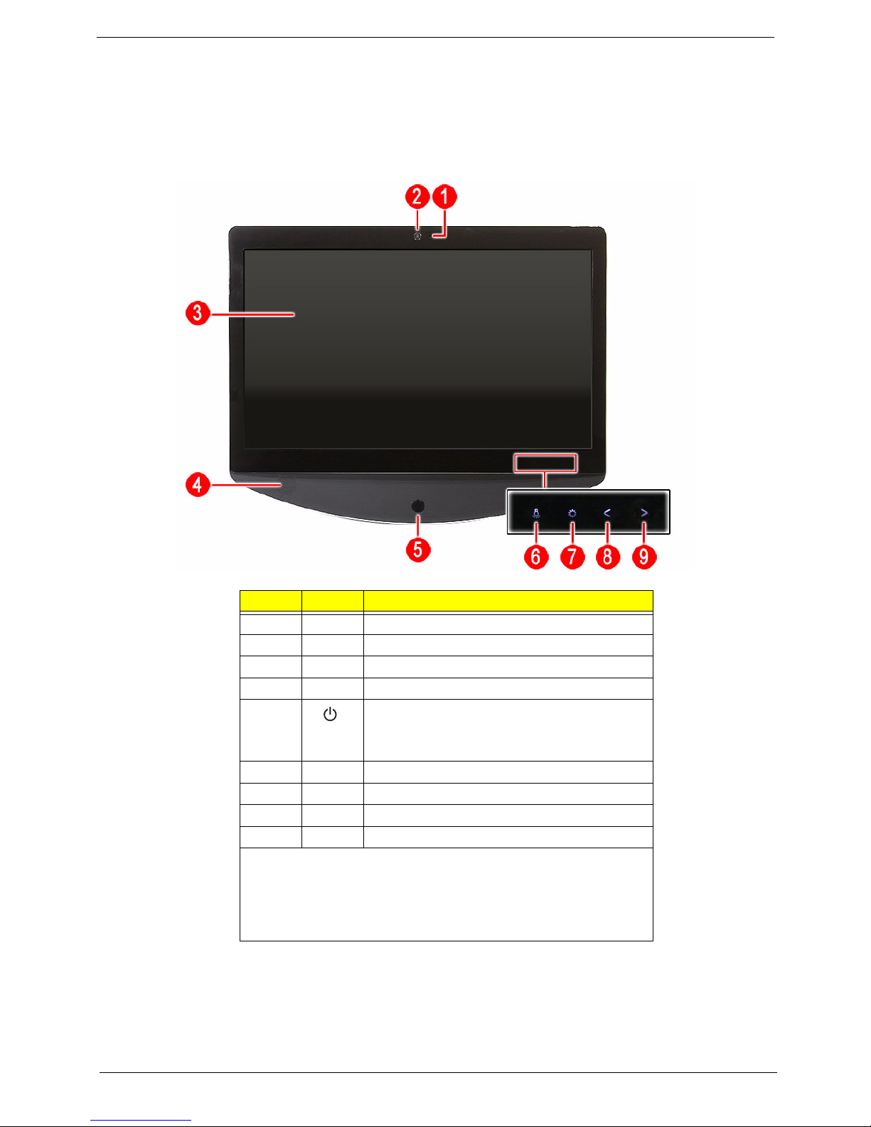
Front View
Item Icon Component
1 Integrated microphone
2 Integrated webcam
3 Display screen
4 Speakers
5 Power button/indicator
• Blue – System is in power-on mode
• Flashing blue – System is in standby mode
6 Auxiliary lighting capacitive key
7 LCD brightness capacitive key
8 Volume decrease capacitive key
9 Volume increase capacitive key
NOTES:
• Icons for the capacitive keys are only visible when the system is
t
urned on.
•The auxiliary lighting capacitive key is designed to provide a light
urce when using a keyboard in low-light conditions.
so
Packard Bell oneTwo M3830 / M3831 AIO Computer Service Guide 3
Page 12

Left View
Item Icon Component Item Icon Component
1 B-CAS card (optional) cover 11 Ethernet port (RJ-45)
2 Optical disc drive (ODD) 12 USB ports
3 I/O cable cover 13 eSATA port
4 9-in-1 card reader 14 DVI to D-Sub port (optional)
5 HD dual digital TV tuner
(opt
ional)
6 Line-in jack 16 HDMI port
7 Line-out jack 17 PS/2 mouse port
8 Microphone jack 18 PS/2 keyboard port
9 Line-in jack 19 AC power jack
10 Line-out jack
15 Monitor port (VGA)
4 Packard Bell oneTwo M3830 / M3831 AIO Computer Service Guide
Page 13
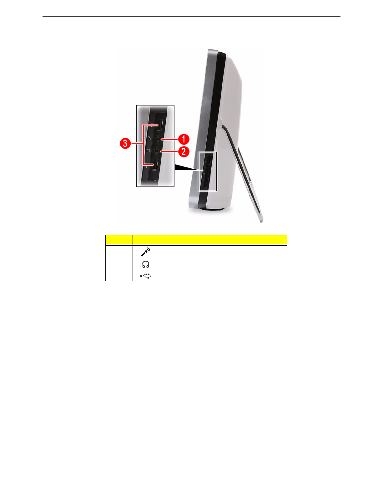
Right View
Item Icon Component
1 Microphone jack
2 Line-out jack
3 USB ports
Packard Bell oneTwo M3830 / M3831 AIO Computer Service Guide 5
Page 14

Rear View
Item Component
1 Ventilation slots
2 Mounting holes for wall mount option
3 Computer stand
4 Kensington slot
6 Packard Bell oneTwo M3830 / M3831 AIO Computer Service Guide
Page 15

Hardware Specifications
Processor
• Socket: LGA775 socket, 775 pin contacts
• Package type: 45 nm (except for Intel Celeron 450, 65 nm)
• Thermal design power: 65 W (except for Intel C
Item Specification
®
Core™ 2 Duo Desktop Processors Intel® Core™ 2
Intel
Model E8600 E8500 E7600 E7500 Q8400s
CPU speed 3.33 GHz 3.16 GHz 3.06 GHz 2.93 GHz 2.66 GHz
Bus speed 1333 MHz 1333 MHz 1066 MHz 1066 MHz 1333 MHz
Bus/core ratio 10.0 9.5 11. 5 11. 0 8.0
L2 cache size 6 MB 6 MB 3 MB 3 MB
Item Specification
®
Pentium® Dual-Core Processors for Desktop
Intel
Model E6600 E5700 E5500
CPU speed 3.06 GHz 3.0 GHz 2.8 GHz
Bus speed 1066 MHz 800 MHz 800 MHz
Bus/core ratio 11.5 – 14.0
L2 cache size 2 MB 2 MB
eleron 450, 35 W)
2 MB
Quad Processors
4 MB
Item Specification
®
Celeron® Processor Family
Intel
Model E3500 E3400 450
CPU speed 2.70 GHz 2.60 GHz 2.20 GHz
Bus speed 800 MHz 800 MHz 800 MHz
Bus/core ratio – 13.0 12.5
L2 cache size 1 MB 1 MB 1 MB
Package type 45 nm 45 nm 65
Chipsets
Item Specification
North bridge Intel G43 Express Chipset
South bridge Intel ICH10 Chipset
I/O controller
SIO ITE 8720
BIOS
Item Specification
BIOS chip AMI BIOS
Setup utility CMOS Setup Utility
nm
Packard Bell oneTwo M3830 / M3831 AIO Computer Service Guide 7
Page 16

Memory
Item Specification
Controller Integrated in the Intel G43 Express Chipset
Number of DIMM slot 4
Maximum memory 8 GB (using four 2 GB modules)
Data rate 1333 MT/s
Supported capacities 1 or 2 GB
DIMM type 240-pin DDR3 SO-DIMM
Supported brands Apacer, Kingston, Transcend, Unifosa, Samsung
Population rule
You can install memory modules in any combination as long as they match the above
specifications.
Hard Disk Drive
Item Specification
Controller Integrated in the Intel ICH10 Chipset
Form factor 3.5-inch 9.5 mm
Interface S ATA o r S ATA I I
Supported capacities
320 GB WD WD3200AAJS-22L7A0 (7200 rpm)
500 GB WD WD5000AAKS-22M9A0 (7200 rpm)
640 GB • HGST HDT721064SLA360 / HDS721064CLA332 (7200 rpm)
• WD WD6400AAKS-22A7B2 (7200 rpm)
1 TB • Seagate ST31000528AS (7200 rpm)
•HGST HDS721010CLA332 (7200 rpm)
• WD WD10EADS-22M4B0 (5400 rpm)
1.5 TB • Seagate ST31500341AS (7200 rpm)
• WD WD15EADS-22P8B0
(5400 rpm)
Optical Disc Drive
Item Specification
Controller Integrated in the Intel ICH10 Chipset
Type DVD-Super Multi double-layer or Blu-ray Disc combo drive option
Form factor Slim type
Tray height (mm)) 12.7 mm
Interface SATA
Supported models
DVD-Super Multi
do
uble-layer drive
Blu-ray Disc
co
mbo drive
8 Packard Bell oneTwo M3830 / M3831 AIO Computer Service Guide
•HLDS GT31N
• PLDS DS-8A5SH
• Panasonic UJ141AL / UJ240A
• HLDS CT21N
Page 17

Ethernet
Item Specification
Controller Intel 82567V Gigabit Ethernet Controller
LAN protocol 10/100/1000 Mbps
LAN connector type
RJ-45
Wireless LAN
Item Specification
Model Lite-On WN6607LH
Protocol 802.11 b/g/n
Form factor
PCIe Mini Card
Bluetooth
Item Specification
Model • Xavi BC10B-04C1
• BC04-ROM CSP A08
Version
Bluetooth 2.1 + EDR
Audio
Item Specification
Controller Realtek ALC888S-VC 7.1+2 Channel High Definition Audio Codec
Features • Two built-in 5W stereo speakers
• Right panel audio jacks
– Headphone jack
– Microphone jack
• Left panel audio jacks
– Line-in, line-out, and microphone jacks
– Line-in and line-out jacks
Webcam
Item Specification
Resolution 2.0 MP
Supported models • Chicony CNFA21321004590L
• Park Orchid C04PL037F
• Primax 50-704A4WNT8
Packard Bell oneTwo M3830 / M3831 AIO Computer Service Guide 9
Page 18

LCD Panel
Item Specification
Screen size (diagonal, inch) 21.5-inch
Type Wide XGA
Resolution 1920 × 1080
Backlight CCFL
Interface LVDS
Brightness (typical) 300 nits
Display colors 16.7M
Aspect ratio 16:9
Contrast ratio 1000:1
Response time (typical) 5 ms
Touchscreen Only for oneTwo M3831
Surface treatment AG type, 3H hard coating, Haze 25
Supported models • Touchcreen panel – Samsung touch panel assembly
• Non-touch panels
– AUO M215HW01 V0 0H LF
– CPT CLAA215FA01 DN5 LF
– LG 2LM215WF1 TLF1 LF
– LPL LM215WF1 TLA1 LF
Inverter board • Darfon VZ.13156.B01
• Sumida IV30260SPEC139
Power Supply Unit
Item Specification
Output (max.) 220 W
Supported models • Lite-On PS-5221-06A2
• Delta DPS-220UB-1 A
• Chicony CPB09-D220R
10 Packard Bell oneTwo M3830 / M3831 AIO Computer Service Guide
Page 19

Chapter 2
System Utilities
CMOS Setup Utility
CMOS Setup Utility is a hardware configuration program built into the system ROM. Since most systems are
already properly configured and optimized, there is normally no need to run this utility.
You will need to run this utility under the following conditions:
• When changing the system configuration including:
• Setting the system time and date
• Configuring the system dr
• Specifying the boot device sequence
• Configuring the power management modes
• Setting up system passwords or making other changes to
• When trying to resolve IRQ conflicts
• When a configuration error is detected by th
make changes to the BIOS settings.
The Setup Utility loads the configuration val
This memory area is not part of the system RAM, which allows configuration data to be retained when power is
turned off. The values take effect when the system is booted. POST uses these values to configure the
hardware. If the values and the actual hardware do not agree, POST generates an error message. You must
run this utility to change the hardware settings from the default or current configuration.
IMPORTANT If you repeatedly receive “Run Setup” messages, the RTC battery located on the mainboard
(BT1) may be defective. In this case, the system cannot retain configuration values in CMOS.
Replace the RTC battery with a new one.
ives and peripherals
the security setup
e system and you are prompted ("Run Setup" message) to
ues in a battery-backed nonvolatile memory called CMOS RAM.
NOTE For ease of reading, CMOS Setup Utility will be simply referred to as “Setup” or “Setup Utility” in this
Service Guide.
Packard Bell oneTwo M3830 / M3831 AIO Computer Service Guide 11
Page 20
Accessing the Setup Utility
1. Turn on the computer.
If the computer is already turned on, save your data and close all open applications, then restart the
computer.
2. During POST, press Delete.
If you fail to press De
lete before POST is completed, you will need to restart the computer.
Use the Up
option.
Some options lead to pop-up dialog boxes that prompt you to verify
options lead to dialog boxes that prompt you for information.
Some options (marked with a ) lead to submenus that enable you to ch
the Up/Down/Left/Right arrow keys to scroll through the items in the submenu
/Down/Left/Right arrow keys to move between the menu options, then press Enter to execute that
that you wish to execute that option. Other
ange the values for the option. Use
12 Packard Bell oneTwo M3830 / M3831 AIO Computer Service Guide
Page 21

Navigating through the Setup Utility
Use the keys listed in the legend bar on the bottom of the Setup screen to work your way through the various
menu and submenu screens of the Setup Utility. The table below lists these legend keys and their respective
functions.
Key Function
Up/Down/Left/
Right arrow keys
Enter • To open the page for the currently selected menu/submenu
PgUp and PgDn Move the cursor to the previous and next page of a multipage menu.
Home Move the cursor to the first page of a multipage menu.
End Move the cursor to the last page of a multipage menu.
+ and - To select a value for the currently selected field (only if it is user-configurable). Press these
Esc If you press this key:
F1 To bring up the
F9 Press to load default system values.
F10 Press to save changes and close the Setup Utility.
Move the cursor to the menu/field you want.The currently selected field will be highlighted.
• To apply a field value.
key
s repeatedly to display all possible entries. A parameter that is enclosed in square
brackets [ ] is user-configurable. Grayed-out parameters are not user-configurable for one
of the following reasons:
• The field value is auto-configured or auto-detected.·
• The field value is informational only.
• The field is password-protected.
• On one of the primary menu screens, the
• On a submenu screen, the previous screen displays.
• When you are making selections from a pop-up menu, closes the pop-up without making
ection.
a sel
General Help window. The General Help window describes other Setup
navigation keys that are not displayed on the legend bar.
Exit menu displays.
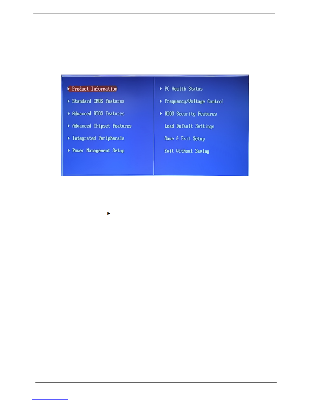
Setup Utility Menus
The Setup Utility has twelve menus for configuring the various system functions. These include:
• Product Information
• Standard CMOS Features
• Advanced BIOS Features
• Advanced Chipset Features
• Integrated Peripherals
• Power Management Setup
NOTES • The screenshots used in this section are for illustration
the same as those in your computer.
• In the descriptive tables following each of the
the default and suggested settings.
• PC Health Status
• Frequency/Voltage Control
• BIOS Security Features
• Load Default Settings
• Save & Exit Setup
• Exit Without Saving
only. The values displayed may not be
menu screen illustrations, settings in boldface are
Packard Bell oneTwo M3830 / M3831 AIO Computer Service Guide 13
Page 22
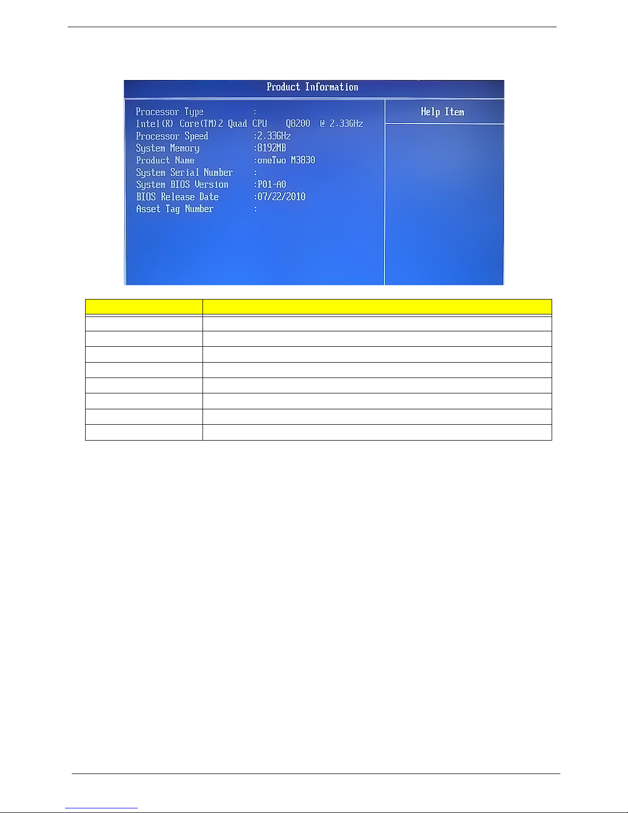
Product Information
.
Field Description
Processor Type Type of processor installed on the system
Processor Speed Speed of the processor installed on the system
System Memory Size of system memory detected during boot-up
Product Name Official model name of the computer.
System Serial Number System serial number.
System BIOS Version Current system BIOS version
BIOS Release Date Date when the CMOS setup utility was released.
Asset Tag Number System asset tag number
14 Packard Bell oneTwo M3830 / M3831 AIO Computer Service Guide
Page 23
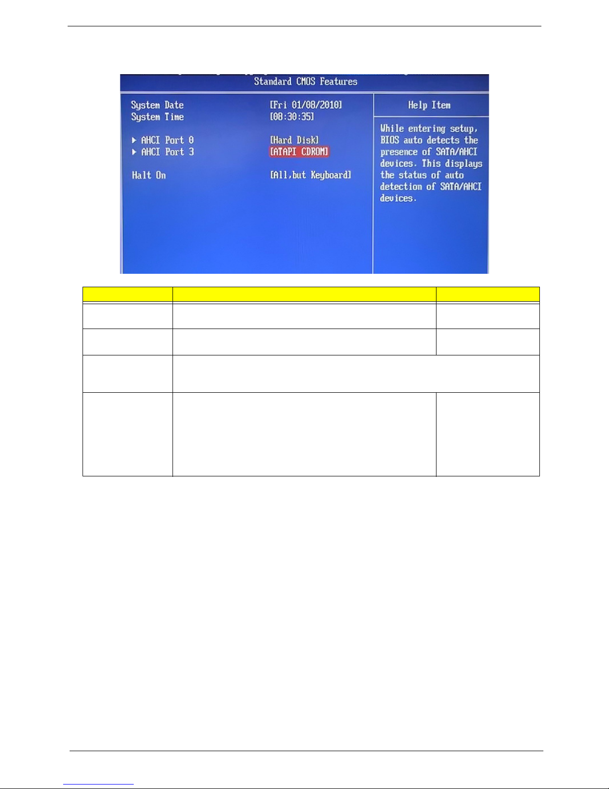
Standard CMOS Features
Field Description Value
System Date Sets the system date. MM/DD/YYYY
(month/day/year)
System Time Sets the system time. HH:MM:SS
(hou
AHCI Port 0
AHCI Port 3
Halt On Determines whether the system will stop for an error during the
Your computer supports four SATA channels, each channel allows one SATA device to be
i
nstalled. Press Enter to display the individual configuration screen of installed SATA
drive(s).
All Errors
PO
ST. Options include:
• All Errors - Any error det
• No Errors - BIOS will ignore any errors detected during
ST
PO
• All, but Keyboard - If a keyboard error is detected, BIOS will
ause the system.
p
ected will pause the system.
No Errors
All, But Keyboard
r:minute:second)
Packard Bell oneTwo M3830 / M3831 AIO Computer Service Guide 15
Page 24
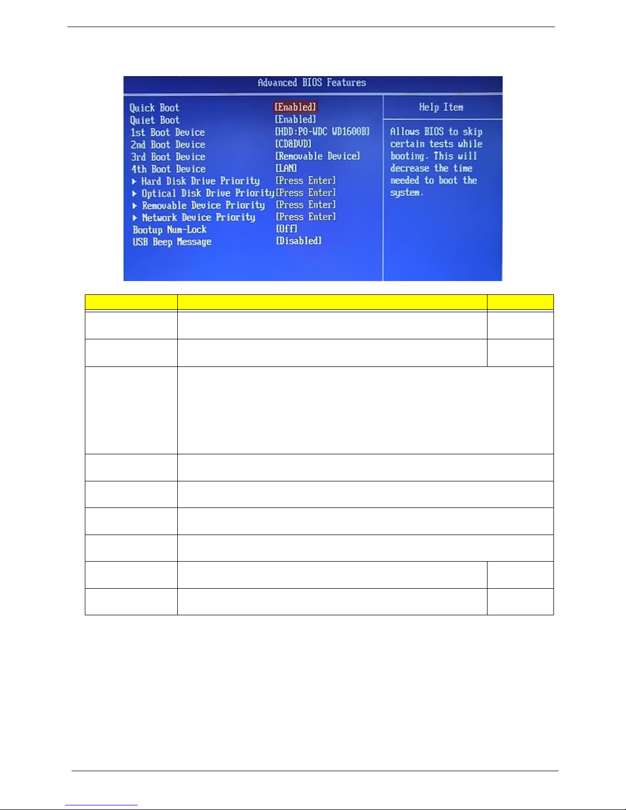
Advanced BIOS Features
Field Description Value
Quick Boot When enabled, the system starts up more quickly be elimination some of
the POST routines.
Quiet Boot When enabled, BIOS will show a full screen logo when booting; if
sabled, BIOS will show the diagnostic POST screen when booting.
di
1st/2nd/3rd/4th
Device
Boot
Hard Disk Drive
ority
Pri
Optical Disk Drive
Pri
ority
Removable Device
Pri
ority
Network Device
Pri
ority
Bootup Num-Lock If you set this item to On, the keyboard Num Lock key will be active when
USB Beep
Mes
sage
Displays the device assigned to the specified boot sequence. The Setup Utility attempts
to boot the operating system in this order. By default, the computer searches for boot
devices in the following order:
• Hard disk
• Optical drive (CD/DVD)
• Removable device
• Network boot (LAN)
Press Enter to specify the boot device priority sequence for the installed hard drive(s).
Press Enter to specify the boot device priority sequence for the installed optical drive.
Press Enter to specify the boot device priority sequence for removable drives.
Press Enter to specify the boot device priority sequence foe available network drives.
t
he computer boots up.
Select whether to allow the BIOS to emit error beeps or display error
messages during USB device enumeration.
Enabled
Disabled
Enabled
Disabled
On
Off
Enabled
Disabled
16 Packard Bell oneTwo M3830 / M3831 AIO Computer Service Guide
Page 25
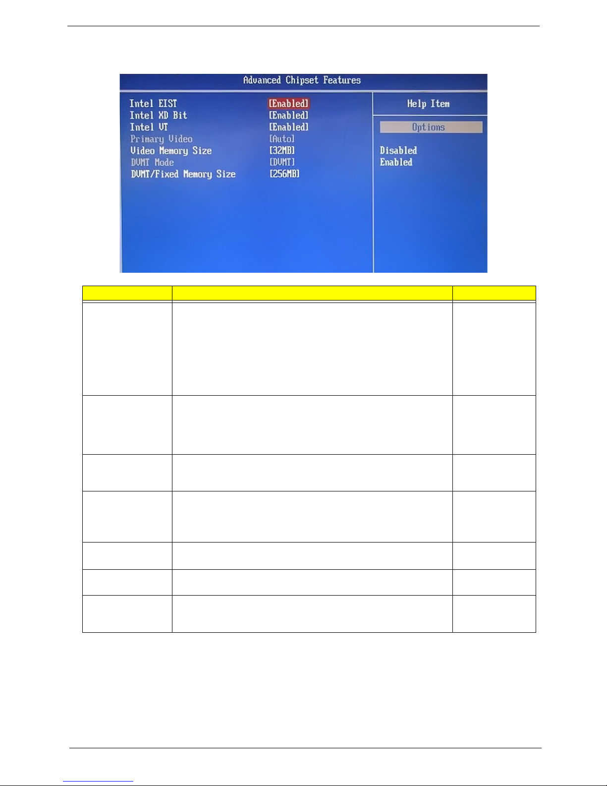
Advanced Chipset Features
Field Description Val ue
Intel EIST Select whether to enable the Enhanced Intel SpeedStep
Technology. EIST allows a compliant OS to dynamically adjust the
processor voltage and core frequency based on system usage. This
can result in decreased average power consumption and decreased
average heat production.
Note: Af
your operating system as well. Consult your OS documentation for
related instructions.
Intel XD Bit Select whether to enable the Intel Execute Disable Bit Technology.
XD Bit
exposure to viruses and malicious-code attacks and prevent
harmful software from executing and propagating on the computer
or network.
Intel VT Select whether to enable the Intel Virtualization Technology. VT
al
independent partitions.
Primary Video When a graphics card is installed, you have the option to select
whi
Note: Whe
sequence is: PCIE, Onboard, then PCI.
Video Memory
ze
Si
DVMT Mode Select the Intel Dynamic Video Memory Technology mode. Fixed
DVMT/Fixed
Memo
ry Size
Displays the size of video memory detected during boot-up. This
applies to systems supporting the ATI HyperMemory technology.
Select to specify the maximum memory size that can be allocated
as graphics memory using the Intel Dynamic Video Memory
Technology.
ter enabling EIST in BIOS Setup, you need to enable it on
is a hardware-based security feature that can reduce
lows a single platform to run multiple operating systems in
ch graphics controller to activate.
n this field is set to Auto, the graphics controller priority
Enabled
Disabled
Enabled
Disabled
Enabled
Disabled
Auto
PCIE
Onboard
PCI
___
32 MB
DVMT
128 MB
256 MB
Maximum
Packard Bell oneTwo M3830 / M3831 AIO Computer Service Guide 17
Page 26
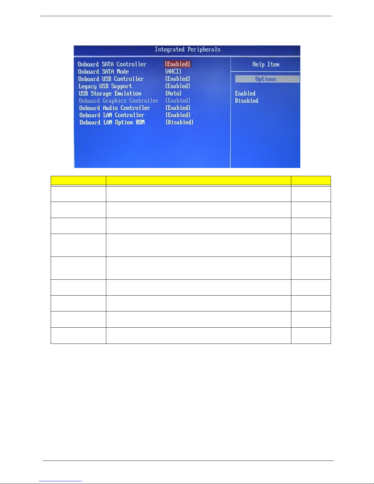
Integrated Peripherals
Field Description Value
Onboard SATA
Controller
Onboard SATA
Mod
e
Onboard USB
Cont
roller
Legacy USB
Suppo
rt
USB Storage
Emul
ation
Onboard Graphics
Cont
roller
Onboard Audio
Cont
roller
Onboard LAN
Cont
roller
Onboard LAN
Op
tion ROM
Enables or disables the onboard SATA controller. Enabled
Set the operating mode for the onboard SATA controller. Native IDE
Enables or disables the onboard USB controller. Enabled
Enables or disables support for a USB mouse and USB keyboard. When
enabled, any attached USB mouse or USB keyboard can control the
system even when there is no USB driver loaded onto the system.
If set to Auto, a USB devices with a capacity of equal or less than 2 GB
will be emulated as a bootable floppy disk.
Enables or disables the onboard graphics controller. Enabled
Enables or disables the onboard audio controller. Enabled
Enables or disables the onboard LAN controller. Enabled
Enables or disables the onboard LAN option ROM function. Enabled
Disabled
Disabled
Enabled
Disabled
Auto
Floppy
Hard Disk
Disabled
Disabled
Disabled
Disabled
18 Packard Bell oneTwo M3830 / M3831 AIO Computer Service Guide
Page 27
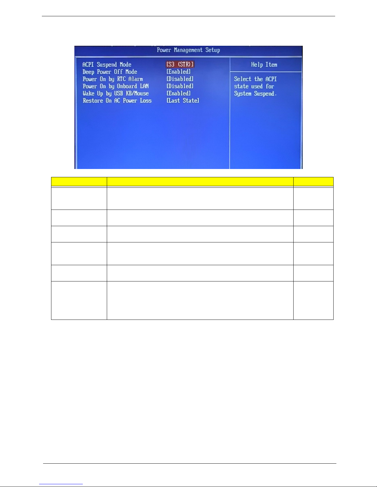
Power Management Setup
Field Description Value
ACPI Suspend
Mode
Deep Power Off
Mod
e
Power On by RTC
Al
arm
Power On by
Onbo
ard LAN
Use this item to define how your system suspends. Default value is S3
(STR), the suspend mode is suspend to RAM, i.e., the system shuts
down with the exception of a refresh current to the system memory.
Enables or disables compliance to the Energy-using Products Lot 6
Directives (EuP Lot 6).
Enables or disables the system to wake up from a power-saving mode
when an RTC alarm occurs.
Enables or disables the system to wake up from a power-saving mode
when the onboard LAN controller received a network message.
S3 (STR)
S1 (POS)
Enabled
Disabled
Enabled
Disabled
Enabled
Disabled
Wake Up by USB
KB/
Mouse
Restore On AC
Power Loss
Enables or disables the system to wake up from a power-saving mode
when a USB keyboard or mouse is used.
Select the power state when an AC power loss occurs.
• Off - The computer remains off until the power button is pressed.
• Last State - The computer reverts to the last power state before the
wer loss occurred.
po
• On - The computer switches back on after the AC power loss.
Enabled
Disabled
Power Off
Power On
Last State
Packard Bell oneTwo M3830 / M3831 AIO Computer Service Guide 19
Page 28
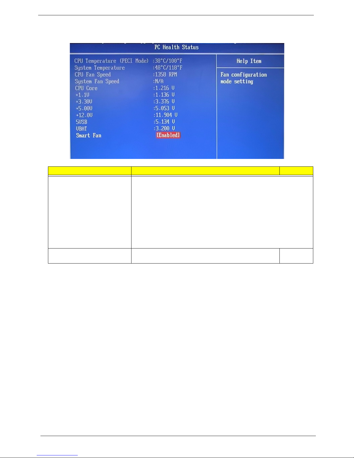
PC Health Status
Field Description Value
CPU Temperature (PECI Mode)
System Temperature
CPU Fan Speed
System Fan Speed
CPU Core
+1.1V
+3.30V
+5.00V
+12.0V
5VSB
VBAT
Smart Fan When enabled, fan speed will speed up or slow down
These items lets you monitor the parameters for critical voltages,
t
emperatures and fan speeds.
pending on the system temperature.
de
Enabled
Disabled
20 Packard Bell oneTwo M3830 / M3831 AIO Computer Service Guide
Page 29

Frequency/Voltage Control
Field Description Value
Clock to All DIMM/PCI/
PCIE
Spread Spectrum When the mainboard's clock generator pulses, the extreme values of
When enabled, clock signals will be sent to the PCI and memory
slots regardless of whether the slot is occupied or not.
th
e pulses creates EMI (electromagnetic interference). Set this field
to Enabled to reduce this EMI level. This reduces interference
problems with other electronics in the area.
Note:
Remember to disable the Spread Spectrum feature if you are
overclocking. A slight jitter can introduce a temporary boost in clock
speed causing the overclocked processor to lock up.
Enabled
Disabled
Enabled
Disabled
Packard Bell oneTwo M3830 / M3831 AIO Computer Service Guide 21
Page 30
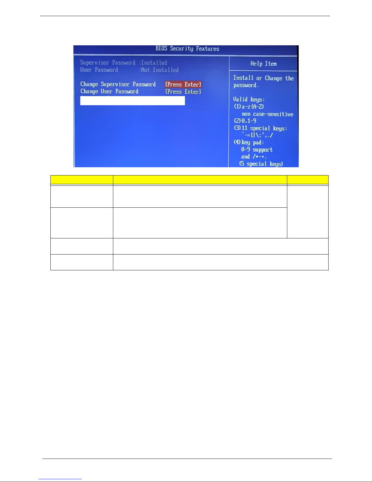
BIOS Security Features
Field Description Value
Supervisor Password Displays the supervisor password status. When set to Installed, this
password will allow the user to access and change all settings in the
Setup Utility.
User Password Displays the user password status. Only the following menus will be
ac
cessible when this password is set as Installed:
• System Date and System Time
• Exit Without Saving
Change Supervisor
Password
Change User
Password
Press En
Press En
ter to change the supervisor password.
ter to change the user password.
Installed
Not Installed
Note the following before you define a system password:
• The maximum length of password contains 8 alphanumeric characters. The following keys are valid:
– A-Z, a-z (case-insensitive)
– 0-9
– ` - + [ ] \ ; ' , . /,
– Special keypad characters: 0-9 / * - +
• When you are prompted to enter a password, you have three tries before the system halts. Do not forget
your password. If you forget your password, you may have to return your computer to your dealer to reset
it.
22 Packard Bell oneTwo M3830 / M3831 AIO Computer Service Guide
Page 31

To set a system password:
NOTE You need to set a supervisor password first before setting the user password.
1. Select Change Supervisor Password or Change User Password, then press Enter.
The password box appears.
2. Type a password then press Enter.
IMPORTANT Be very careful when typing your password because the characters do not appear on the
n. Only shaded blocks representing each typed character are visible.
scree
3. Retype the p
You will be prompted to save the new password.
4. Press Enter.
5. Press F1
assword to verify the first entry, then press Enter.
0 to save the password and close the Setup Utility.
To change a system password:
1. Select Change Supervisor Password or Change User Password, then press Enter.
The password box appears.
2. T
ype the original password, then press Enter.
3. Type a new password, then press Enter.
4. Retype the new password to verify the first entry, then press Enter.
You will be prompted to save the new password.
5. Press Enter.
6. Press F1
0 to save the password and close the Setup Utility.
To remove a system password:
NOTE When the supervisor password is removed, the user password will also be remove.
1. Select Change Supervisor Password or Change User Password, then press Enter.
The password box appears.
2. T
ype the original password, then press Enter.
3. Press Enter tw
You will be prompted to confirm the password removal.
4. Press Enter.
5. Press F1
ice without entering anything in the new and confirm password fields.
0 to save the changes you made and close the Setup Utility.
Packard Bell oneTwo M3830 / M3831 AIO Computer Service Guide 23
Page 32

Load Default Settings
Execute this menu to load the factory-default settings for all Setup parameters. Keyboard shortcut: F9
Perform the steps below to load the system default settings:
1. Selec
2. Selec
3. Press F10 to save the changes you made and close the Setup Utility.
t Load Default Settings, then press Enter.
You will be prompted to load the system defaults.
t OK, then press Enter.
24 Packard Bell oneTwo M3830 / M3831 AIO Computer Service Guide
Page 33

Save & Exit Setup
Execute this menu to save the changes made and closes the Setup Utility. Keyboard shortcut: F10
Exit Without Saving
Execute this menu to closes the Setup Utility without making any changes.
Packard Bell oneTwo M3830 / M3831 AIO Computer Service Guide 25
Page 34

26 Packard Bell oneTwo M3830 / M3831 AIO Computer Service Guide
Page 35

Chapter 3
System Disassembly
This chapter provides step-by-step instructions on how to disassemble the computer for maintenance and
troubleshooting purposes.
Disassembly Tools
In performing the disassembly process, you will need the following tools:
• Wrist-grounding strap and conductive mat for preventing electrostatic discharge
• Philips screwdriver
• Hex screwdriver
• Flat screwdriver
• Scissors (for cutting the PSU cable ties)
NOTES • To reinstall the system components and assemble the unit, perform the disassembly procedures in
reverse.
• The screws for the different components vary in size. D
screws with their corresponding components to avoid mismatches when putting back the
components.
uring the disassembly process, group the
Pre-disassembly Procedure
Before proceeding with the disassembly procedure, perform the steps listed below:
1. Make sure th
2. T
urn off the power to the computer and all peripherals.
3. Unplug the power cord from the computer.
4. Unplug the network cable and all connected peripheral devices from the computer.
5. Place the computer on
at the optical disc drive and the card reader slot are empty.
a flat, steady surface with the rear cover facing upward.
Packard Bell oneTwo M3830 / M3831 AIO Computer Service Guide 27
Page 36

Disassembly Procedures
Removing the Computer Stand
1. Perform the “Pre-disassembly Procedure” on page 27.
2. Use a fl
at screwdriver to pry off the plastic shells covering the computer stand screws.
3. Remove the screws securin
Quantity Color To rque Part Number
6 Black 4.0–4.5 kgf-cm 86.00N85.266
4. Remove the computer st
and.
g the computer stand.
28 Packard Bell oneTwo M3830 / M3831 AIO Computer Service Guide
Page 37

Removing the I/O Cable Cover
1. Use a flat screwdriver to pry off the I/O cable cover.
2. Remove the I/
O cable cover
Removing the Rubber Feet
1. Perform the “Pre-disassembly Procedure” on page 27.
2. Use a fl
at screwdriver to pry off the rubber feet from the computer base.
Packard Bell oneTwo M3830 / M3831 AIO Computer Service Guide 29
Page 38

Removing the Rear Cover
1. Remove the computer stand by following the procedure described on page 28.
2. Remove the I/O cable cover and the rubber feet by following the procedures described on page 29.
3. Use a flat screwdriver to carefully pry loose the rear cover from the front bezel.
The picture below shows the location of the plastic sna
4. Toggle the cover from left to right to loosen its hold on the front bezel, then detach the rear cover.
ps securing the rear cover to the front bezel.
Removing the I/O Cable Plate
1. Remove the rear cover by following the procedure described in the previous section.
2. Push the latch to disengage the I/O cable plate from the chassis.
30 Packard Bell oneTwo M3830 / M3831 AIO Computer Service Guide
Page 39

3. Remove the I/O cable plate.
Removing the Optical Disc Drive
1. Remove the rear cover by following the procedure described on page 30.
2. Remove the screw securing
the ODD.
Quantity Color To rque Part Number
1 Silver 4.0–4.5 kgf-cm 86.00B75.240
3. Slide the ODD outward, then disconnect the ODD SATA cable from the drive.
Packard Bell oneTwo M3830 / M3831 AIO Computer Service Guide 31
Page 40

4. Remove the ODD from the chassis.
5. Remove the screw securi
Quantity Color To rque Part Number
1 Silver 1.3–1.5 kgf-cm 86.7A122.4R0
6. Det
ach the ODD bezel from the module.
ng the ODD bracket.
32 Packard Bell oneTwo M3830 / M3831 AIO Computer Service Guide
Page 41

Removing the Wireless Module
1. Remove the rear cover by following the procedure described on page 30.
2. Remove the screw securing the scaler board cover.
Quantity Color To rque Part Number
1 Black 4.0–4.5 kgf-cm 86.00B75.240
3. Slid
4. Discon
e the scaler board cover towards the speaker area to disengage the cover tabs from the chassis, then
remove the scaler board cover.
nect the antenna cables from the WLAN module.
Packard Bell oneTwo M3830 / M3831 AIO Computer Service Guide 33
Page 42

5. Remove the screw securing the WLAN module.
Quantity Color To rque Part Number
1 Black 1.3–1.5 kgf-cm 86.7A122.4R0
6. Remove the WLAN module.
7. Remove the t
apes securing the antenna cables, then free the cables the chassis.
34 Packard Bell oneTwo M3830 / M3831 AIO Computer Service Guide
Page 43

8. Use a flat-blade screwdriver to pry off the antennas from the top side of the chassis.
Removing the Scaler Board
1. Remove the rear cover by following the procedure described on page 30.
2. Remove the scale
3. Discon
nect all the cables from the scaler board.
r board cover by following steps 2 and 3 of the previous section.
Packard Bell oneTwo M3830 / M3831 AIO Computer Service Guide 35
Page 44

4. Remove the screws securing the scaler board.
Quantity Color To rque Part Number
3 Silver 4.0 kgf-cm 86.00B75.240
5. Remove the scaler board.
A circuit board that is >10 cm
above image. Follow local regulations for disposing this type of circuit board.
36 Packard Bell oneTwo M3830 / M3831 AIO Computer Service Guide
2
has been highlighted with a yellow rectangle as shown in the
Page 45

Removing the USB/Audio Board
1. Remove the rear cover by following the procedure described on page 30.
2. Remove the screw securing the USB/audio board cover.
Quantity Color To rque Part Number
1 Silver 4.0–4.5 kgf-cm 86.00B75.240
3. Slid
4. Discon
e the USB/audio board cover outward to disengage the cover tabs from the chassis, then remove the
USB/audio board cover.
nect the two cables from the USB/audio board.
Packard Bell oneTwo M3830 / M3831 AIO Computer Service Guide 37
Page 46

5. Remove the screws securing the USB/audio board.
Quantity Color To rque Part Number
1 Silver 4.0 kgf-cm 86.00B75.240
6. Slide the USB/audio board out of its tabs.
A circuit board that is >10 cm
above image. Follow local regulations for disposing this type of circuit board.
38 Packard Bell oneTwo M3830 / M3831 AIO Computer Service Guide
2
has been highlighted with a yellow rectangle as shown in the
Page 47

Removing the Wall Mount Plate
1. Remove the rear cover by following the procedure described on page 30.
2. Remove the screws securing the wall mount plate.
Quantity Color To rque Part Number
1 Silver 4.0–4.5 kgf-cm 86.00B75.240
3. Slide the wall mount plate towards the HDD area to disengage the plate tabs from the chassis, then
remove the wall mount plate.
Packard Bell oneTwo M3830 / M3831 AIO Computer Service Guide 39
Page 48

Removing the Inverter Board
1. Remove the wall mount plate by following the procedure described on the previous section.
2. Remove the screw securing the inverter board cover.
Quantity Color To rque Part Number
1 Silver 4.0–4.5 kgf-cm 86.00B75.240
3. Remove the inverter board cover.
4. Discon
nect all cables from the inverter board.
40 Packard Bell oneTwo M3830 / M3831 AIO Computer Service Guide
Page 49

5. Remove the screws securing the inverter board.
Quantity Color To rque Part Number
2 Silver 4.0 kgf-cm 86.00B75.240
6. Remove the inverter board.
A circuit board that is >10 cm
above image. Follow local regulations for disposing this type of circuit board.
Packard Bell oneTwo M3830 / M3831 AIO Computer Service Guide 41
2
has been highlighted with a yellow rectangle as shown in the
Page 50

Removing the TV Tuner Card
1. Remove the wall mount plate by following the procedure described in the previous section.
2. Disconnect the TV tuner card cable.
3. Remove the screw securing th
Quantity Color To rque Part Number
1 Black 4.0–4.5 kgf-cm 86.00B75.240
4. Discon
nect TV tuner card from its expansion slot.
e TV tuner card bracket.
42 Packard Bell oneTwo M3830 / M3831 AIO Computer Service Guide
Page 51

Removing the Graphics Card
1. Remove the wall mount plate by following the procedure described on page 39.
2. Remove the hex screws securing the DVI to D-Sub cable to the I/O panel cover (a), then detach the cable
from the panel cover (b).
Quantity Color To rque Part Number
2 Silver 4.5 kgf-cm
86.80536.7R2
3. Disconnect the HDMI cable from the graphics card. Remove the hex screws securing the DVI to D-Sub
cable to the graphics card (a), then detach the cable from the card (b).
Quantity Color To rque Part Number
2 Silver 4.5 kgf-cm 86.80536.7R2
Packard Bell oneTwo M3830 / M3831 AIO Computer Service Guide 43
Page 52

4. Disconnect the graphics card assembly from its expansion slot.
5. Remove the screw securin
Quantity Color To rque Part Number
1 Silver 4.0–4.5 kgf-cm 86.00B75.240
6. Discon
nect the graphics card from its riser board.
g the graphics card bracket.
A circuit board that is >10 cm
above image. Follow local regulations for disposing this type of circuit board.
44 Packard Bell oneTwo M3830 / M3831 AIO Computer Service Guide
2
has been highlighted with a yellow rectangle as shown in the
Page 53

7. Remove the screws securing the riser board.
Quantity Color To rque Part Number
2 Silver 4.0–4.5 kgf-cm 86.00B75.240
8. Remove the riser boa
rd from its bracket.
Removing the Hard Disk Drive
1. Remove the graphics card by following the procedure described on the previous section.
2. Disconnect the power and SATA cables from the hard drive.
Packard Bell oneTwo M3830 / M3831 AIO Computer Service Guide 45
Page 54

3. Slide the HDD assembly outward to disengage the assembly from the chassis, then remove the HDD
assembly.
4. Remove the screws securing
the hard drive to its cage.
Quantity Color To rque Part Number
4 Silver 4.0–4.5 kgf-cm 86.00J44.C60
5. Use a small metal screwdriver to push the hard drive out of its cage (a), then pull out the drive out (b).
46 Packard Bell oneTwo M3830 / M3831 AIO Computer Service Guide
Page 55

Removing the Heat Sink Fan (HSF) Assembly
1. Remove the wall mount plate by following the procedure described on page 39.
2. Disconnect the HSF cable from its mainboard connector.
3. Loo
4. Remove the HSF
sen the HSF's spring-loaded screws in a diagonally opposite pattern (an "X" pattern).
Quantity Color To rque Part Number
4 Silver 4.0–4.5 kgf-cm –
assembly.
Packard Bell oneTwo M3830 / M3831 AIO Computer Service Guide 47
Page 56

Removing the Processor
1. Remove the HSF assembly by following the procedure described on the previous section.
2. Disengage the load lever from its latch, then rotate the load lever to the open position.
3. Op
4. Ge
en the retention plate to expose the socket body.
ntly lift the processor out of its socket.
CAUTION DO NOT lay the processor on its base to avoid
IMPORTANT When installing a processor:
• Note the golden arrow on the corner to make sure the processo
the socket.
• Moisten a soft cloth with isopropyl alcohol and clean the processor die to remove any
thermal grease residue. Wipe the die surface several times to make sure that no particles
or dust contaminants are evident. Allow the alcohol to evaporate before continuing. Apply
just enough thermal grease to evenly coat the surface of the processor die.
48 Packard Bell oneTwo M3830 / M3831 AIO Computer Service Guide
bending or damaging the pins underneath it.
r is properly oriented over
Page 57

Removing the Memory Modules
1. Remove the wall mount plate by following the procedure described on page 39.
2. Open the holding clips securing the memory modules (a), then remove the memory modules from the
DIMM slots (b).
Removing the RTC Battery
1. Remove the wall mount plate by following the procedure described on page 39.
2. Det
ach the socket latch from the RTC battery, then remove the RTC battery from its socket.
The RTC battery has been highlighted with a yellow circle in the above image. Detach the RTC
battery
and follow local regulations for disposing it.
Packard Bell oneTwo M3830 / M3831 AIO Computer Service Guide 49
Page 58

Removing the Power Supply Unit
1. Remove the wall mount plate by following the procedure described on page 39.
2. Disconnect the 4-pin and 24-pin ATX power cables from their mainboard connectors.
a. Press the top portion of the cable’s retaining latch
b. Pull
the cable straight up from its connector.
3. Discon
nect the PSU extension cable.
50 Packard Bell oneTwo M3830 / M3831 AIO Computer Service Guide
Page 59

4. Remove the screws securing the PSU bracket.
Quantity Color To rque Part Number
1 (#1) Black 4.0 kgf-cm 86.3AR26.8R0
2 (#2-3) Silver 4.0 kgf-cm
86.00J44.C60
5. Det
ach the PSU bracket from the power supply unit.
6. Remove the screws securing the PSU
to the chassis.
Quantity Color To rque Part Number
2 Silver 4.0 kgf-cm 86.00J44.C60
Packard Bell oneTwo M3830 / M3831 AIO Computer Service Guide 51
Page 60

7. Remove the power supply unit from the chassis.
Removing the Mainboard
1. Remove the wall mount plate by following the procedure described on page 39.
2. Remove the TV tuner card by following the procedure described on page 42.
3. Remove the grap
4. Remove the hard drive by following the procedure described on page 46.
5. Remove the HSF assembly by following the procedure described on page 47.
6. Remove
7. Remove the memory modules by following the procedure described on page 49.
8. Remove the RTC battery by following the procedure described on the previous section.
9. Discon
the processor by following the procedure described on page 48.
nect the HDD and ODD SATA cables from the mainboard.
hics card by following the procedure described on page 43
52 Packard Bell oneTwo M3830 / M3831 AIO Computer Service Guide
Page 61

10. Disconnect all cables from the upper edge area of the mainboard.
11. Remove the screws securing
Quantity Color To rque Part Number
6 Black 4.0 kgf-cm 86.00B75.240
the mainboard.
Packard Bell oneTwo M3830 / M3831 AIO Computer Service Guide 53
Page 62

12. Remove the mainboard.
A circuit board that is >10 cm
above image. Follow local regulations for disposing this type of circuit board.
2
has been highlighted with a yellow rectangle as shown in the
Removing the I/O Shield
1. Remove the mainboard by following the procedure described on the previous section.
2. Push the I/O shield to remove it from the chassis.
54 Packard Bell oneTwo M3830 / M3831 AIO Computer Service Guide
Page 63

Removing the Touchscreen Control Board
1. Remove the PSU by following the procedure described on page 50.
2. Push the tabs securing the touchscreen control board.
3. Remove the touchscree
A circuit board that is >10 cm
above image. Follow local regulations for disposing this type of circuit board.
4. Discon
nect all cables from the touchscreen control board.
n control board and turn it over to expose the cable connectors underneath it.
2
has been highlighted with a yellow rectangle as shown in the
Packard Bell oneTwo M3830 / M3831 AIO Computer Service Guide 55
Page 64

Removing the Bluetooth Module
1. Remove the PSU by following the procedure described on page 50.
2. Push the tabs securing the Bluetooth module.
3. Remove the Blue
underneath it.
4. Discon
nect the Bluetooth cable from the module.
tooth module from the front bezel and turn it over to expose the cable connector
56 Packard Bell oneTwo M3830 / M3831 AIO Computer Service Guide
Page 65

Removing the Power Button Assembly
1. Remove the PSU by following the procedure described on page 50.
2. Push the tabs securing the power button assembly.
3. Remove the po
wer button assembly from the front bezel.
Removing the Speakers
1. Remove the PSU by following the procedure described on page 50.
2. Remove the touchscree
3. Remove the Bluetooth module by following the procedure described on page 57.
n control board by following the procedure described on page 56.
Packard Bell oneTwo M3830 / M3831 AIO Computer Service Guide 57
Page 66

4. Remove the screws securing the speakers.
Quantity Color To rque Part Number
4 Black 4.5 kgf-cm 86.3AR26.8R0
5. Remove the speakers and set it aside on top of the chassis
Removing the LCD Assembly
IMPORTANT For oneTwo M3831 only: If the LCD touchscreen panel becomes defective, the LCD panel
with the touchscreen film and the touchscreen control board should be replace. Return all
three components for RMA.
1. Remove the I/O cable plate by following the procedure described on page 30.
2. Remove the op
3. Remove the scaler board by following the procedure described on page 35
4. Remove the USB/audio board by following the procedure described on page 37.
5. Remove
6. Remove the PSU by following the procedure described on page 50.
tical drive by following the procedure described on page 31.
the mainboard by following the procedure described on page 52.
58 Packard Bell oneTwo M3830 / M3831 AIO Computer Service Guide
Page 67

7. Disconnect the IR cable from the front bezel.
8. Discon
9. Discon
nect the light bar cables from the light bars.
nect the capacitive LED board cable.
10. Discon
nect the webcam cable.
Packard Bell oneTwo M3830 / M3831 AIO Computer Service Guide 59
Page 68

11. Remove the screws securing the LCD assembly.
Quantity Color To rque Part Number
5 Black 4.0 kgf-cm 86.3AR26.8R0
12. Push back th
e plastic snaps securing the LCD assembly to the front bezel.
60 Packard Bell oneTwo M3830 / M3831 AIO Computer Service Guide
Page 69

13. Detach the LCD assembly from the front bezel.
Removing the Chassis
1. Remove the LCD assembly by following the procedure described on page 59.
2. Remove the screws securing
Quantity Color To rque Part Number
4 Silver 4.0 kgf-cm 86.00B75.240
the chassis to the LCD panel.
Packard Bell oneTwo M3830 / M3831 AIO Computer Service Guide 61
Page 70

3. Remove the chassis from the LCD panel and lay it down beside the panel.
4. Rele
ase the inverter cables from the chassis.
5. Remove the t
apes securing the system cables, then release the cables from their chassis latches.
62 Packard Bell oneTwo M3830 / M3831 AIO Computer Service Guide
Page 71

Removing the LCD LVDS Cable
1. Remove the chassis by following the procedure described on page 62.
2. Remove the tapes securing the LCD cable.
3. Press
the two sides of the LCD cable connector then pull to disconnect the cable from the LCD board.
Removing the LCD Panel Brackets
1. Remove the chassis by following the procedure described on page 62.
2. Remove the screws securing the
LCD panel bracket (a), then detach the brackets (b).
Quantity Color To rque Part Number
4 Black 4.0 kgf-cm 86.00B75.240
Packard Bell oneTwo M3830 / M3831 AIO Computer Service Guide 63
Page 72

Removing the Webcam Module
1. Remove the LCD assembly by following the procedure described on page 59.
2. Remove the black tape protecting the webcam module.
3. Push the tabs securing the webcam module.
4. Remove the web
cam module.
64 Packard Bell oneTwo M3830 / M3831 AIO Computer Service Guide
Page 73

Removing the Capacitive LED Board
1. Remove the LCD assembly by following the procedure described on page 59.
2. Remove the capacitive LED board cover.
3. Pry the cap
acitive LED board from the front bezel.
Packard Bell oneTwo M3830 / M3831 AIO Computer Service Guide 65
Page 74

Removing the Light Bars
1. Remove the LCD assembly by following the procedure described on page 59.
2. Remove the black tape protecting the light bars.
3. Push the tabs securing both ends of the two light bars.
4. Remove the light bars from the front bezel.
66 Packard Bell oneTwo M3830 / M3831 AIO Computer Service Guide
Page 75

Chapter 4
Troubleshooting
This chapter lists the POST error indicators and BIOS beep codes. Instructions for general troubleshooting,
BIOS recovery and clearing CMOS data are also provided.
Hardware Diagnostic Procedure
1. Obtain as much detail as possible about the symptoms of the system failure.
2. V
erify the symptoms by attempting to recreate the failure by running the diagnostic tests or repeating the
same operation.
3. Refer to “Power System Check” procedure on the next section and the “Beep Codes” section on page 82
to determine which corrective action to take.
System Check Procedures
IMPORTANT The diagnostic tests described in this chapter are only intended to test Acer products.
on-Acer products, prototype cards, or modified options can give false errors and invalid
N
system responses.
Power System Check
If the system can be powered on, skip this section. Proceed to the “System Internal Inspection” procedure on
the next page.
If the system will not power on, do the following:
• Check if the power cable is properly connected to the
• Check if the voltage selector switch is se
t to the correct voltage setting.
AC power jack and a functional AC power source.
System External Inspection
1. Inspect the power and LED indicators on the front panel. Go to “Front View” section on page 3 for the
location and description of the LED behaviour.
2. Make sure th
3. Make sure th
If the cause of the failure is still can not be determin
procedure described on the next page.
at the ventilation slots on the rear panel are not blocked.
at there is no point of contact in the system that can cause a power short.
ed, perform the “System Internal Inspection”
Packard Bell oneTwo M3830 / M3831 AIO Computer Service Guide 67
Page 76

System Internal Inspection
1. Turn off the power to the computer and all peripherals.
2. Unplug the power cord from the computer.
3. Unplug the network cable and all connected peripheral devices from the computer.
4. Place the computer on
5. Remove the TV stand and the rear cover.
6. Remove the wall mount plate.
7. V
erify that the processor, memory module(s), and expansion board(s) are properly seated.
8. Verify that all power and data cables are firmly and properly attached to the installed drives.
9. Verify that all cable connections inside the system are firmly and properly attached to their appropriate
mainboard connectors.
10. Verify that all components are Acer-qualified and supported.
11. Rein
12. Reinstall the rear cover and the TV stand.
13. Power on the system.
stall the wall mount plate.
If the cause of the failure is stil
checkpoints during the system startup.
a flat, steady surface.
l can not be determined, review the POST messages and BIOS
Checkpoints
A checkpoint is either a byte or word value output to I/O port 80h. The BIOS outputs checkpoints during
bootblock and Power-On Self Test (POST) to indicate the task the system is currently executing. Checkpoints
are very useful in aiding software developers or technicians in debugging problems that occur during the
pre-boot process.
Viewing BIOS Checkpoints
Viewing all checkpoints generated by the BIOS requires a checkpoint card, also referred to as a POST card or
POST diagnostic card. These are ISA or PCI add-in cards that show the value of I/O port 80h on a LED
display. Checkpoints may appear on the bottom right corner of the screen during POST. This display method
is limited, since it only displays checkpoints that occur after the video card has been activated.
NOTE
Boot Block Initialization Code Checkpoints
The boot block initialization code sets up the chipset, memory, and other components before system memory
is available. The following table describes the type of checkpoints that may occur during the boot block
initialization portion of the BIOS.
Please note that checkpoints may differ between different platforms based on system
configuration. Checkpoints may change due to vendor requirements, system chipset or option
ROMs from add-in PCI devices.
Checkpoint Description
Before D1 Early chipset initialization is done. Early super I/O initialization is done including RTC and
keyboa
D1 Perform keyboard controller BAT test. Che
suspend state. Save power-on CPUID value in scratch CMOS.
D0 Go to flat mode with 4GB limit and GA20 enabled. Verify the bootblock checksum.
D2 Disable CACHE before memory detection
flat mode is enabled.
rd controller. NMI is disabled.
ck if waking up from power management
. Execute full memory sizing module. Verify that
68 Packard Bell oneTwo M3830 / M3831 AIO Computer Service Guide
Page 77

Checkpoint Description
D3 If memory sizing module not e
bootblock code. Do additional chipset initialization. Re-enable CACHE. Verify that flat
mode is enabled.
D4 Test base 512 KB memory. Adjust policies and cache first 8 MB. Set stack.
D5 Bootblock code is copied from ROM to lower system me
BIOS now executes out of RAM.
D6 Both key sequence and OEM specific method is che
forced. Main BIOS checksum is tested. If BIOS recovery is necessary, control flows to
checkpoint E0. See the “Boot Block Recovery Code Checkpoints” section for more
information.
D7 Restore CPUID value back into register. The Boo
moved to system memory and control is given to it. Determine whether to execute serial
flash.
D8 The Runtime module is uncompressed into memory. CPUID information is stored in
emory.
m
D9 Store the Uncompressed pointer for future use in PMM. Copying Main BIOS into memory.
ves all RAM below 1 MB Read-Write including E000 and F000 shadow areas but
Lea
closing SMRAM.
DA Restore CPUID value back into register. Give control to BIOS POST
cutePOSTKernel). See the “POST Code Checkpoints” section for more information.
(Exe
xecuted, start memory refresh and do memory sizing in
mory and control is given to it.
cked to determine if BIOS recovery is
tblock Runtime interface module is
Boot Block Recovery Code Checkpoints
The boot block recovery code gets control when the BIOS determines that a BIOS recovery is required
because the user has forced the update or the BIOS checksum is corrupt. Refer to “BIOS Recovery” section
on page 83 for more information. The following table describes the
the boot block recovery po
Checkpoint Description
E0 Initialize the floppy controller in the
controller is initialized. 8259 interrupt controller is initialized. L1 cache is enabled.
E9 Set up floppy controller and data. Attempt to read from floppy.
EA Enable ATAPI hardware. Attempt to read from ARMD and ATAPI CDROM.
EB Disable ATAPI hardware. Jump back to
EF Read error occurred on media. Jump back to checkpoint EB.
E9 or EA Determine information about root directory of recovery media.
F0 Search for pre-defined recovery file name in root directory.
F1 Recovery file not found.
F2 Start reading FAT table and analyze FAT to find the clusters occupied by the recovery file.
F3 Start reading the recovery file c
F5 Disable L1 cache.
FA Check the validity of the recovery fi
part.
FB Make flash write enabled through chipset and OEM specific method. Detect proper flash
p
F4 The recovery file size does not equal the found flash part size.
FC Erase the flash part.
FD
Program the flash part.
rtion of the BIOS.
super I/O. Some interrupt vectors are initialized. DMA
checkpoint E9.
luster by cluster.
le configuration to the current configuration of the flash
art. Verify that the found flash part size equals the recovery file size.
type of checkpoints that may occur during
Packard Bell oneTwo M3830 / M3831 AIO Computer Service Guide 69
Page 78

Checkpoint Description
FF The flash has been updated successfully. Make flash write disabled. Disable ATAPI
hardware. Restore CPUID value back into register. Give control to F000 ROM at
F000:FFF0h.
POST Code Checkpoints
The POST code checkpoints are the largest set of checkpoints during the BIOS preboot process. The
following table describes the type of checkpoints that may occur during the POST portio
Checkpoint Description
03 Disable NMI, Parity, video for EGA, and DMA co
data area. Also initialize BIOS modules on POST entry and GPNV area. Initialized CMOS
mentioned in the Kernel Variable "wCMOSFlags."
as
04 Check CMOS diagnostic byte to determine if battery pow
OK. Verify CMOS checksum manually by reading storage area.
If the CMOS checksum is bad, update CMOS with po
passwords. Initialize status register A.
Initializes data variables that are based on CMOS setup questions.
Initializes both the 8259 compatible PICs in the system
05 Initializes the interrupt controlling hardware (generally PIC) and interrupt vector table.
06 Do R/W test to CH-2 count reg. Initialize CH-0 as system timer
handler. Enable IRQ-0 in PIC for system timer interrupt. Traps INT1Ch vector to
"POSTINT1ChHandlerBlock."
08 Initializes the CPU. The BAT test is being done on KBC. Program the keyboard controller
comma
0A Initializes the 8042 compatible Key Board Controller.
0B Detects the presence of PS/2 mouse.
0C Detects the presence of Keyboard in KBC port.
0E Testing and initialization of different Input Devices. Also,
Traps the INT09h vector, so that the POST INT0
Uncompress all available language, BIOS logo, and Silent logo modules.
13 Early POST initialization of chipset registers.
24 Uncompress and initialize any platform specific BIOS mod
checkpoint.
30 Initialize System Management Interrupt.
2A Initializes different devices through
See DIM Code Checkpoints section for more information.
2C Initializes different devices. Detects and initializes the video adapter installed in the
system th
2E Initializes all the output devices.
31 Allocate memory for ADM module and unc
initialization. Initialize language and font modules for ADM. Activate ADM module.
33 Initializes the silent boot module. Set the window for displaying text information.
37 Displaying sign-on message, CPU information, setup key message, and any OEM
specific information
38 Initializes different devices through DIM. See DIM Code Checkpoints section for more
information
39 Initializes DMAC-1 & DMAC-2.
3A
Initialize RTC date/time.
nd byte is being done after Auto detection of KB/MS using AMI KB-5.
DIM.
at have optional ROMs.
.
. USB controllers are initialized at this point.
ntrollers. Initialize BIOS, POST, Runtime
er is OK and CMOS checksum is
wer-on default values and clear
update the Kernel Variables.
9h handler gets control for IRQ1.
ules. GPNV is initialized at this
ompress it. Give control to ADM module for
n of the BIOS.
.Install the POSTINT1Ch
70 Packard Bell oneTwo M3830 / M3831 AIO Computer Service Guide
Page 79

Checkpoint Description
3B Test for total memory installed in the system. Also, Check for DEL or ESC keys to limit
memory test. Display total memory in the system.
Checkpoint Description
3C Mid POST initialization of chipset registers.
40 Detect different devices (Parallel ports, serial
ports, and coprocessor in CPU, ... etc.)
successfully installed in the system and update the BDA, EBDA…etc.
50 Programming the memory hole or any kind of imp
lementation that needs an adjustment in
system RAM size if needed.
52 Updates CMOS memory size from memory found in
memory test. Allocates memory for
Extended BIOS Data Area from base memory. Programming the memory hole or any kind
of implementation that needs an adjustment in system RAM size if needed.
60 Initializes Num-Lock status and programs the KBD typematic rate.
75 Initialize Int-13 and prepare for IPL detection.
78 Initializes IPL devices controlled by BIOS and option ROMs.
7A Initializes remaining option ROMs.
7C Generate and write contents of ESCD in NVRam.
84 Log errors encountered during POST.
85 Display errors to the user and gets the user response for error.
87 Execute BIOS setup if needed / requested. Che
ck boot password if installed.
8C Late POST initialization of chipset registers.
8E Program the peripheral parameters. Enable/Disable NMI as selected.
90 Late POST initialization of system manag
ement interrupt.
A0 Check boot password if installed.
A1 Clean-up work needed before booting to OS.
A2 Takes care of runtime image preparation for different BIOS
modules. Fill the free area in
F000h segment with 0FFh. Initializes the Microsoft IRQ Routing Table. Prepares the
runtime language module. Disables the system configuration display if needed.
A4 Initialize runtime language module. Display boot option popup menu.
A7 Displays the system configuration screen if enabled.
Initialize the CPU’s before boot,
which includes the programming of the MTRR’s.
A8 Prepare CPU for OS boot including final MTRR values.
A9 Wait for user input at config display if needed.
AA Uninstall POST INT1Ch vector and INT09h vector. Deinitializes the ADM module.
AB Prepare BBS for Int 19 boot.
AC End of POST initialization of chipset registers.
B1 Save system context for ACPI.
00
Passes control to OS Loader (typically INT19h).
Packard Bell oneTwo M3830 / M3831 AIO Computer Service Guide 71
Page 80

DIM Code Checkpoints
The Device Initialization Manager (DIM) gets control at various times during BIOS POST to initialize different
system busses. The following table describes the main checkpoints where the DIM module is accessed.
Checkpoint Description
2A Initialize different buses and perform the follo
(function 0); Static Device Initialization (function 1); Boot Output Device Initialization
(function 2). Function 0 disables all device nodes, PCI devices, and PnP ISA cards. It also
assigns PCI bus numbers. Function 1 initializes all static devices that include manual
configured onboard peripherals, memory and I/O decode windows in PCI-PCI bridges,
and noncompliant PCI devices. Static resources are also reserved. Function 2 searches
for and initializes any PnP, PCI, or AGP video devices.
38 Initialize different buses and perform the follo
Initialization (function 3); IPL Device Initialization (function 4); General Device Initialization
(function 5). Function 3 searches for and configures PCI input devices and detects if
system has standard keyboard controller. Function 4 searches for and configures all PnP
and PCI boot devices. Function 5 configures all onboard peripherals that are set to an
automatic configuration and configures all remaining PnP and PCI devices.
wing functions: Reset, Detect, and Disable
wing functions: Boot Input Device
POST Error Indicators
When a system error is detected during POST (Power On Self Text), the Setup utility will switch to diagnostic
mode and will either:
• Displays a POST error message, or
• Emits a series of beep codes
POST Error Messages
POST error messages tell users what failure the system has detected. Some error messages could be related
to a hardware device. Others may indicate a problem with a device configuration. In some cases an error
message may include recommendations for troubleshooting or require that you press the Enter key to display
recommendations. Follow the instructions on the screen. It is recommended that you correct the error before
proceeding, even if the computer appears to boot successfully.
IMPORTANT If your system fails after you make changes in th
Setup again and load Setup defaults to correct the error.
e Setup menus, reboot the computer, enter
72 Packard Bell oneTwo M3830 / M3831 AIO Computer Service Guide
Page 81

Memory
Message Description
Gate20 Error The BIOS is unable to properly control the mainboard’s Gate A20 function, which
ntrols access of memory over 1 MB. This may indicate a problem with the
co
mainboard.
Multi-Bit ECC Error This message will only occur on systems using ECC enabled memory modules.
C memory has the ability to correct single-bit errors that may occur from faulty
EC
memory modules.
A multiple bit corruption of memory
cannot correct it. This may indicate a defective memory module.
Parity Error Fatal Memory Parity Error. System halts after displaying this message.
RAM R/W test failed This message is displayed by the AMIBIOS8 when
CMOS Memory Size
ong
Wr
The base memory (memory below 1MB) size that is reported in the CMOS (offset
15h) mismatches with the actual size detected. This condition may occur when the
hole is set at 512K base memory or when CMOS is corrupted.
has occurred, and the ECC memory algorithm
the RAM read/write test fails.
Boot
Message Description
Boot Failure... This is a generic message indicating the BIOS coul
device. This message is usually followed by other information concerning the
device.
Invalid Boot Diskette A diskette was found in the drive, but it is not configured as a bootable diskette.
Drive Not Ready The BIOS was unable to access the drive because it indicated it was not ready for
a transfer. This is often reported by drives when no media is present.
dat
A: Drive Error The BIOS attempted to configure the A: dri
properly configure the device. This may be due to a bad cable or faulty diskette
drive.
B: Drive Error The BIOS attempted to configure the B: dri
properly configure the device. This may be due to a bad cable or faulty diskette
drive.
Insert BOOT diskette
in A:
Reboot and select
r boot device or
prope
Insert boot media in
selected boot device
NO ROM BASIC This message occurs on some systems when no bootable device can be detected.
The BIOS attempted to boot
diskette.
Reboot and Select proper Boot device or Insert Bo
BIOS could not find a bootable device in the system and/or removable media drive
does not contain media.
BIOS could not find a bootable device in the system and/or removable
media drive does not contain media.
from the A: drive, but could not find a proper boot
ve during POST, but was unable to
ve during POST, but was unable to
d not boot from a particular
ot Media in selected Boot device
Packard Bell oneTwo M3830 / M3831 AIO Computer Service Guide 73
Page 82

Storage Device
Message Description
Primary Master Hard
rror
Disk E
Primary Slave Hard
rror
Disk E
Secondary Master
Hard Disk Erro
Secondary Slave
Hard Disk Erro
3rd Master Hard Disk
or
Err
3rd Slave Hard Disk
or
Err
4th Master Hard Disk
or
Err
4th Slave Hard Disk
or
Err
5th Master Hard Disk
Err
or
5th Slave Hard Disk
or
Err
6th Master Hard Disk
or
Err
6th Slave Hard Disk
or
Err
Primary Master Drive
TAPI Incompatible
- A
Primary Slave Drive -
TAPI Incompatible
A
Secondary Master
ATAPI
Drive Incompatible
Secondary Slave
ATAPI
Drive Incompatible
3rd Master Drive -
TAPI Incompatible
A
r
r
The IDE/ATAPI device configured as Primary Master could not be properly
initialized by the BIOS. This message is typically displayed when the BIOS is trying
to detect and configure IDE/ATAPI devices in POST.
The IDE/ATAPI device configured as Primary Slave could not be properly initialized
by the BIOS. This message is typically displayed when the BIOS is trying to detect
and configure IDE/ATAPI devices in POST.
The IDE/ATAPI device configured as Secondary Master could not be properly
initialized by the BIOS. This message is typically displayed when the BIOS is trying
to detect and configure IDE/ATAPI devices in POST.
The IDE/ATAPI device configured as Secondary Slave could not be properly
initialized by the BIOS. This message is typically displayed when the BIOS is trying
to detect and configure IDE/ATAPI devices in POST.
The IDE/ATAPI device configured as Master in the 3rd IDE controller could not be
properly initialized by the BIOS. This message is typically displayed when the BIOS
is trying to detect and configure IDE/ATAPI devices in POST.
The IDE/ATAPI device configured as Slave in the 3rd IDE controller could not be
properly initialized by the BIOS. This message is typically displayed when the BIOS
is trying to detect and configure IDE/ATAPI devices in POST.
The IDE/ATAPI device configured as Master in the 4th IDE controller could not be
properly initialized by the BIOS. This message is typically displayed when the BIOS
is trying to detect and configure IDE/ATAPI devices in POST.
The IDE/ATAPI device configured as Slave in the 4th IDE controller could not be
properly initialized by the BIOS. This message is typically displayed when the BIOS
is trying to detect and configure IDE/ATAPI devices in POST.
The IDE/ATAPI device configured as Master in the 5th IDE controller could not be
properly initialized by the BIOS. This message is typically displayed when the BIOS
is trying to detect and configure IDE/ATAPI devices in POST.
The IDE/ATAPI device configured as Slave in the 5th IDE controller could not be
properly initialized by the BIOS. This message is typically displayed when the BIOS
is trying to detect and configure IDE/ATAPI devices in POST.
The IDE/ATAPI device configured as Master in the 6th IDE controller could not be
properly initialized by the BIOS. This message is typically displayed when the BIOS
is trying to detect and configure IDE/ATAPI devices in POST.
The IDE/ATAPI device configured as Slave in the 6th IDE controller could not be
properly initialized by the BIOS. This message is typically displayed when the BIOS
is trying to detect and configure IDE/ATAPI devices in POST.
The IDE/ATAPI device configured as Primary Master failed an ATAPI compatibility
test. This message is typically displayed when the BIOS is trying to detect and
configure IDE/ATAPI devices in POST.
The IDE/ATAPI device configured as Primary Slave failed an ATAPI compatibility
test. This message is typically displayed when the BIOS is trying to detect and
configure IDE/ATAPI devices in POST.
The IDE/ATAPI device configured as Secondary Master failed an ATAPI
compatibility test. This message is typically displayed when the BIOS is trying to
detect and configure IDE/ATAPI devices in POST.
The IDE/ATAPI device configured as Secondary Slave failed an ATAPI compatibility
test. This message is typically displayed when the BIOS is trying to detect and
configure IDE/ATAPI devices in POST.
The IDE/ATAPI device configured as Master in the 3rd IDE controller failed an
ATAPI compatibility test. This message is typically displayed when the BIOS is
trying to detect and configure IDE/ATAPI devices in POST.
74 Packard Bell oneTwo M3830 / M3831 AIO Computer Service Guide
Page 83

Message Description
3rd Slave Drive ATAPI Incompatible
The IDE/ATAPI device configured as Slave in the 3rd IDE controller failed an ATAPI
compatibility test. This message is typically displayed when the BIOS is trying to
detect and configure IDE/ATAPI devices in POST.
4th Master Drive -
TAPI Incompatible
A
The IDE/ATAPI device configured as Master in the 4th IDE controller failed an
ATAPI compatibility test. This message is typically displayed when the BIOS is
trying to detect and configure IDE/ATAPI devices in POST.
4th Slave Drive -
TAPI Incompatible
A
The IDE/ATAPI device configured as Slave in the 4th IDE controller failed an ATAPI
compatibility test. This message is typically displayed when the BIOS is trying to
detect and configure IDE/ATAPI devices in POST.
5th Master Drive -
TAPI Incompatible
A
The IDE/ATAPI device configured as Master in the 5th IDE controller failed an
ATAPI compatibility test. This message is typically displayed when the BIOS is
trying to detect and configure IDE/ATAPI devices in POST.
5th Slave Drive -
TAPI Incompatible
A
The IDE/ATAPI device configured as Slave in the 5th IDE controller failed an ATAPI
compatibility test. This message is typically displayed when the BIOS is trying to
detect and configure IDE/ATAPI devices in POST.
6th Master Drive -
TAPI Incompatible
A
The IDE/ATAPI device configured as Master in the 6th IDE controller failed an
ATAPI compatibility test. This message is typically displayed when the BIOS is
trying to detect and configure IDE/ATAPI devices in POST.
6th Slave Drive -
TAPI Incompatible
A
The IDE/ATAPI device configured as Slave in the 6th IDE controller failed an ATAPI
compatibility test. This message is typically displayed when the BIOS is trying to
detect and configure IDE/ATAPI devices in POST.
S.M.A.R.T. Capable
but Command F
ailed
The BIOS tried to send a S.M.A.R.T. message to a hard disk, but the command
transaction failed.
This message can be reported by an ATAPI device using the S.M.A.R.T. error
porting standard. S.M.A.R.T. failure messages may indicate the need to replace
re
the hard disk.
S.M.A.R.T.
Command
Failed
The BIOS tried to send a S.M.A.R.T. message to a hard disk, but the command
transaction failed.
This message can be reported by an ATAPI device using the S.M.A.R.T. error
porting standard. S.M.A.R.T. failure messages may indicate the need to replace
re
the hard disk.
S.M.A.R.T. Status
BAD, Backup
and
Replace
A S.M.A.R.T. capable hard disk sends this message when it detects an imminent
failure.This message can be reported by an ATAPI device using the S.M.A.R.T.
error reporting standard. S.M.A.R.T. failure messages may indicate the need to
replace the hard disk.
S.M.A.R.T. Capable
nd Status BAD
a
A S.M.A.R.T. capable hard disk sends this message when it detects an imminent
failure.
This message can be reported by an ATAPI device using the S.M.A.R.T. error
reporting standard. S.M.A.R.T. failure messages may indicate the need to replace
the hard disk.
Packard Bell oneTwo M3830 / M3831 AIO Computer Service Guide 75
Page 84

Virus-related
Message Description
BootSector Write!! The BIOS has detected software attempting to write to a drive’s boot sector. This is
gged as possible virus activity. This message will only be displayed if Virus
fla
Detection is enabled in AMIBIOS setup.
VIRUS: Continue
(Y/N)?
If the BIOS detects possible virus activity, it will prompt the user. This message will
only be displayed if Virus Detection is enabled in AMIBIOS setup.
System Configuration
Message Description
DMA-1 Error Error initializing primary DMA controller. This is a fatal error, often indication a
problem with system hardware.
DMA-2 Error Error initializing secondary DMA controller. This is a fatal error, often indication a
problem with system hardware.
DMA Controller Error POST error while trying to initialize the DMA controll
indication a problem with system hardware.
Checking NVRAM...
te Failed
Upda
Microcode Error BIOS could not find or load the CPU Microcode Update to the CPU. This message
NVRAM Checksum
VRAM
Bad, N
Cleared
Resource Conflict More than one system device is trying to use the same non-shareable resources
NVRAM Ignored The NVRAM data used to store Plug’n’Play (PnP) dat
NVRAM Bad The NVRAM data used to store Plug’n’Play (PnP) dat
Static Resource
ct
Confli
PCI I/O conflict A PCI adapter generated an I/O resource conflict when configured by BIOS POST.
PCI ROM conflict A PCI adapter generated an I/O resource conflict when configured by BIOS POST.
PCI IRQ conflict A PCI adapter generated an I/O resource conflict when configured by BIOS POST.
PCI IRQ routing table
error
Timer Error Indicates an error while programming the count register of channel 2 of the 8254
Refresh timer test
iled
fa
Interrupt Controller-1
error
Interrupt Controller-2
error
BIOS could not write to the NVRAM block. This message appears when the FLASH
part is write-protected or if there is no FLASH part (System uses a PROM or
EPROM).
only app
new CPU is installed in a mainboard with an outdated BIOS. In this case, the BIOS
must be updated to include the Microcode Update for the new CPU.
There was an error in while validating the NVRAM data. This causes POST to clear
the NVRAM data.
(Memo
configuration in POST.
configuration in POST due to a data error.
Two or more Static Devices are trying to use the same resource space (usually
Memory or I/O).
BIOS POST (DIM code) found a PCI device in the system but was unable to figure
out
incomplete description of the PCI Interrupt Routing of the system.
timer
BIOS POST found that the refresh timer hardware failed to pass the Refresh
Retrace Test.
BIOS POST could not initialize the Master In
problem with system hardware.
BIOS POST could not initialize the Slave Interrupt Controller. This may indicate a
problem with system hardware.
lies to INTEL CPUs. The message is most likely to appear when a brand
ry or I/O).
how to route an IRQ to the device. Usually this error is causing by an
. This may indicate a problem with system hardware.
terrupt Controller. This may indicate a
er. This is a fatal error, often
a was not used for system
a was not used for system
76 Packard Bell oneTwo M3830 / M3831 AIO Computer Service Guide
Page 85

CMOS
Message Displayed Description
CMOS Date/Time Not
Set
CMOS Battery Low CMOS battery is low. This message usually
CMOS Settings
ong
Wr
CMOS Checksum
Bad
The CMOS date and/or time are invalid.
the system time in AMIBIOS Setup.
to be replaced. It could also appear when the user intentionally discharges the
CMOS battery.
CMOS settings are invalid. This error can be resolved by using AMIBIOS Setup.
CMOS contents failed the Checksum check. Indicates that the CMOS data has
been changed by a program other than the BIOS or that the CMOS is not retaining
its data due to malfunction. This error can typically be resolved by using AMIBIOS
Setup.
This error can be resolved by readjusting
indicates that the CMOS battery needs
Miscellaneous
Message Displayed Description
KBC BAT Test failed Keyboard controller BAT test failed. This may indicate a problem with keyboard
ntroller initialization.
co
Keyboard Error Keyboard is not present or the hardware is not
controller is initialized.
PS/2 Keyboard not
und
fo
PS/2 Mouse not
und
fo
Keyboard/Interface
Err
or
Unlock Keyboard PS/2 keyboard is locked. User needs to unlock the keyboard to continue the BIOS
System Halted The system has been halted. A reset or powe
<INS> Pressed Indicates that <INS> key is pressed during the BIOS POST
Password check
iled
fa
Unknown BIOS error.
or code = 004Ah
Err
Unknown BIOS error.
or code = 004Bh
Err
Floppy Controller
ilure
Fa
PS/2 keyboard support is enabled in the BIOS setup but the device is not detected.
PS/2 mouse support is enabled in the BIOS setup but the device is not detected.
Keyboard controller failure. This may indicate a problem with system hardware.
ST.
PO
machine. This message appears after a fatal error has been detected.
use default CMOS settings.
The password entered does not match the password set in the setup. This condition
may occur for both Supervisor and User password verification.
This message is displayed when ADM module is not present in the AMIBIOS8
ROM.
This message is displayed when language module is not present in the AMIBIOS8
ROM.
Error in initializing legacy Floppy Controller.
responding when the keyboard
r cycle is required to reboot the
. The POST will load and
Packard Bell oneTwo M3830 / M3831 AIO Computer Service Guide 77
Page 86

Index of Symptom-to-FRU Error Messages
To use the information in this section to diagnose a problem:
1. Find the error s
2. If directed
If no check procedure is indicated, the first Action/FRU item listed in the right column is the most likely
cause.
ymptom in the left column.
to a check procedure, replace the FRU indicated in the check procedure.
NOTE If you cannot find a symptom or an error in this list and the prob
Problems” on page 65.
Processor/Processor Fan-related Symptoms
Symptom/Error Action/FRU
Processor fan does not run but power
ply fan runs.
sup
Processor test failed. • Processor
NOTE Normally, the processor fan should be operative, and the processor clock setting should be exactly
set to match its speed requirement before diagnosing any processor problems.
Mainboard and Memory-related Symptoms
Symptom/Error Action/FRU
Memory test failed. • Memory module
Incorrect memory size shown or repeated
ring POST.
du
System works but fails to enter power
saving mode when the Power Management
Mode is set to Enabled.
Blinking cursor only; system does not work. • IDE drive connection/cables
• Ensure the system is not in power saving mode.
• With the system powered on, measure the voltage of the
processor fan connector. Its reading should be +12Vdc. If the
reading shows normal, but the fan still does not work, then
replace the heat sink fan.
• Mainboard
• Mainboard
• Mainboard
• Insert the memory modules in the DIMM sockets properly,
then reboot the system.
• Memory module
• Mainboard
• Enter CMOS Setup and load the default settings. In Windows
systems, check settings in Power Management Property of
the Control Panel.
• Reload software from Recovery CD.
• IDE disk drives
• See “Undetermined Problems”.
• Mainboard
lem remains, see “Undetermined
NOTE Ensure the memory modules are installed prop
diagnosing any system problems.
78 Packard Bell oneTwo M3830 / M3831 AIO Computer Service Guide
erly and the contact leads are clean before
Page 87

Hard Disk Drive-related Symptoms
Symptom/Error Action/FRU
Hard disk drive test failed. • Enter CMOS Setup and load the default settings.
• Hard disk drive cable
• Hard disk drive
• Mainboard
Hard disk drive cannot format completely. • Enter CMOS Setup and load the default settings.
• Hard disk drive cable
• Hard disk drive
• Mainboard
Hard disk drive has write error. • Enter CMOS Setup and load the default settings.
• Hard disk drive
Hard disk drive LED fails to light, but
system operates
normally.
• With the system power on, measure the voltage of the HDD
LED connector.
• HDD LED cable
NOTE Make sure the hard disk drive is configured correctly in CMOS Setup and that cable/jumper are set
correctly before diagnosing any hard disk drive problems. (If only one drive is installed, please
make sure the drive is connected to master connector or the drive is set to master.)
Optical Disc Drive-related Symptoms
Symptom/Error Action/FRU
CD/DVD-ROM drive LED doesn't come on
t works normally.
bu
• Enter CMOS Setup and load the default settings.
•DIMM
• Mainboard
CD/DVD-ROM drive LED flashes for more
than 30 seconds before LED shutting off.
Software asks to reinstall disc. Software
splays a reading CD/DVD error.
di
CD/DVD-ROM drive cannot load or eject
when the system is turned on and its eject
button is pressed and held.
• CD/DVD-ROM may have dirt or foreign material on it. Check
th a known good disc.
wi
• CD/DVD-ROM is not inserted properly.
• CD/DVD-ROM is damaged.
• Disconnect all cables from CD/DVD-ROM drive except power
cable, then press the eject button to try to unload the disc.
• CD/DVD-ROM drive power cable
• CD/DVD-ROM drive
CD/DVD-ROM drive does not read and
there are no messages are displayed.
• CD may have dirt or foreign material on it. Check with a
known good disc.
• Ensure the CD/DVD-ROM driver is installed properly.
• CD/DVD-ROM drive.
CD/DVD-ROM drive can play audio CD but
no sound output.
• Ensure the headphone jack of the CD/DVD-ROM has an
output.
• Turn up the sound volume.
• Speaker power/connection/cable.
• CD/DVD-ROM drive.
NOTE Make sure the optical disc drive is configured correctly i
correctly and the drive’s optical lens is clean before diagnosing any optical drive problems.
Packard Bell oneTwo M3830 / M3831 AIO Computer Service Guide 79
n CMOS Setup, the cable/jumper are set
Page 88

Real-Time Clock-related Symptoms
Symptom/Error Action/FRU
Real-time clock is inaccurate. • Ensure the information in the Standard CMOS Feature of
BIOS Setup is set
correctly.
• RTC battery
• Mainboard
Audio-related Symptoms
Symptom/Error Action/FRU
Audio software program invoked but no
• Speaker power/connection/cable
sound comes from speakers.
Modem-related Symptoms
Symptom/Error Action/FRU
Modem ring cannot wake up system from
nd mode.
suspe
• For an external modem, make sure Power on By Ring in
BIOS Setup or Power Management is set to Enabled. For the
PCI modem, make sure Wake up by PCI card is set to
Enabled.
• If a PCI modem card is used, reinsert the modem card to the
PCI slot firmly or replace the modem card.
• In Win 98, ensure the telephone application is configured
correctly for your modem and set to receive messages and/or
fax.
Data/fax modem software program invoked
bu
t cannot receive/send data/fax
Fax/voice modem software program
voked but has no sound output. (Data
in
• Ensure the modem card is installed properly.
• Ensure the modem voice-in cable from modem adapter card
is connected to the mainboard
files are received normally; voice from
modem cannot be produced, but system
sound feature works normally.)
Video and Monitor-related Symptoms
Symptom/Error Action/FRU
Video memory test failed.Video adapter
ed.
fail
Display problem
• Incorrect colors
• No high intensity
• Missing, broken, or incorrect characters
• Blank monitor (dark)
• Blank monitor (bright)
• Distorted image
• Unreadable monitor
Display changing colors. • Monitor signal connection/cable
80 Packard Bell oneTwo M3830 / M3831 AIO Computer Service Guide
• Remove all non-factory-installed cards.
• Load default settings (if screen is readable).
• Mainboard
• Monitor signal connection/cable
• Monitor
• Video adapter card
• Mainboard
• Video adapter card
• Mainboard
Page 89

Printer-related Symptoms
Symptom/Error Action/FRU
Printing failed. • Ensure the printer driver is prop
erly installed. Refer to the
printer service manual.
• Printer
• Printer cable
• Mainboard.
Printer problems. • Refer to the service manual for the printer.
Keyboard-related Symptoms
Symptom/Error Action/FRU
Some or all keys on keyboard do not work. • Keyboard
Power Supply-related Symptoms
Symptom/Error Action/FRU
Pressing the power button does not turn off
the system
. (Only unplugging the power
cord from electrical outlet can turn off the
• Ensure the Soft-off by PWR-BTTN in CMOS Setup (under
Power Management) is not set to Instant-off.
• Power switch cable assembly
system.)
Pressing the power button does not turn on
• Power switch cable assembly.
the system
Executing software shutdown from
Windows98 Start menu does not turn off the
• Enter CMOS Setup and load the default settings.
• Reload software from Recovery CD.
system. (Only pressing power button can
turn off the system).
No system power, or power s
not running.
upply fan is
• Power supply
• Mainboard
Packard Bell oneTwo M3830 / M3831 AIO Computer Service Guide 81
Page 90

Beep Codes
When no error message is displayed but the computer stops during POST, listen for beep codes.
Beep Status Possible Causes
One short beep. System ready System is OK.
Continuous one
ng beep
lo
One long beep, then
ort beeps and
two sh
repeat
One long beep, then
e short beep
on
Two short beeps. CMOS failure CMOS checksum error
Memory not installed or
memory error
VGA not installed or
VGA error
BIOS failure BIOS damaged. Processor jump to boot block to execute
Undetermined Problems
NOTE • Verify that all attached devices are supp
• Verify that the power supply being used at the time of the failure is operating correctly. (See
“Power System Check” on page 67)
• Something is wrong with the memory installed
• There is problem accessing the memory (i.e., mainboard
pr
oblem)
• The mainboard can not access the video card for some
reasons. Either the video card is not working, its memory
is not accessible, or its BIOS may be corrupt.
• Something is wrong with the mainboard.
the default procedure.
orted by the computer.
Follow the procedures below to isolate the failing FRU. Do not isolate non-defective FRU.
1. Power off the computer.
2. Visually check them for damage. If any problems are found, replace the FRU.
3. Remove or disconnect all of the following devices:
• Non-Acer devices
• Printer, mouse, and other external devices
• Hard disk drive
•DIMM
• CD/DVD-ROM drive
• Expansion boards
4. Power on
5. Determine
6. If th
If the problem persists, replace the mainboard, and then LCD assembly (one at a time). Do not replace a
non-defective FRU.
the computer.
if the problem has been resolved.
e problem does not recur, reconnect the removed devices one at a time until you find the failed FRU.
82 Packard Bell oneTwo M3830 / M3831 AIO Computer Service Guide
Page 91

BIOS Recovery
When you boot up the computer and you hear one long beep, followed by a shorter one, the system BIOS is
damaged. This maybe cause by an interruption during a BIOS flash procedure (e.g. a power outage) or a
corrupted BIOS code, which will cause the system to go into an unbootable state.You need to access and
execute the boot block program to reboot the computer and recover the regular BIOS code.
Note the following when restoring the BIOS settings:
• Make sure the computer is connected to a UPS u
• The BIOS crisis recovery disk should be prepared i
Vista OS.
Creating the BIOS Crisis Recovery Disk
1. Prepare a removable USB storage device with a capacity size greater than 10 MB.
Note that all data on the USB storage device will be cle
2. Set up a computer running the Windows XP or Windows Vista operating system and plug in the USB
storage device into an available USB port.
3. Copy the target BIOS ROM file to the USB storage device and rename it as “amiboot.rom”.
4. Unplug the USB storage device.
5. Eject
the removable USB storage device from the computer.
Performing a BIOS Recovery
nit during the BIOS recovery process.
n a computer running the Windows XP or Windows
ared during the creation of the crisis disk.
1. Shut down the BIOS failed-computer.
2. Connect the USB storage device containing the “amiboot.rom” file to the failed computer.
3. Press the
The system will now execute the BIOS recovery process. When the process is complete, four short beeps
will be emitted and the computer will automatically reboot.
4. Disconnect the USB storage device from the computer.
5. Press Delete to run the CMOS Setup Utility.
6. Press F9 to load the system default settings.
7. Selec
8. Press F9
9. Selec
power button to turn on the computer.
t Ok, then press Enter.
to save the default settings and close the Setup utility.
t Ok, then press Enter.
Packard Bell oneTwo M3830 / M3831 AIO Computer Service Guide 83
Page 92

Clearing CMOS
You may need to clear the Setup configuration values (CMOS) if the configuration has been corrupted, or if
incorrect settings made in the Setup Utility caused error messages to be unreadable. This procedure will clear
the BIOS supervisor password as well.
Use the JBIOS1 jumper to clear the CMOS data.
• 1-2 position: Normal operation (default)
• 2-3 position: Clear CMOS data
To clear the CMOS data:
1. Turn off the power to the computer and all peripherals.
2. Unplug the power cord from the computer.
3. Unplug the network cable and all connected peripheral devices from the computer.
4. Place the computer on
5. Remove the computer stand, rubber feet, rear cover, and the I/O cable plate by following the procedures
described on pages 28–30.
6. Remove the wall mount plate by following the procedure described on page 39.
7. Remove the graphics card and HDD assemblies by following the procedures described on pages 43–46.
8. If necessa
9. Locate the JBIOS1 jumper on the mainboard.
ry, remove any other assemblies or cables that prevent access to the CMOS clear jumper.
a flat, steady surface with the rear cover facing upward.
10. Remove the ju
11. Return the jumper block to its default 1-2 position.
12. Reinstall the graphics card and HDD assemblies.
13. Rein
14. Reinstall the wall mount plate, I/O cable plate, rear cover, rubber feet, and the computer stand.
15. Connect the power cord to the system.
16. Press the
17. During POST, press Delete to access the Setup Utility.
18. Press F9 to load the system default values.
19. Press F1
84 Packard Bell oneTwo M3830 / M3831 AIO Computer Service Guide
stall any any other assemblies or cables that have previously been removed.
mper block and set it over the 2-3 pins for 20 to 30 seconds.
power button to turn on the computer.
0 to save the changes you made and close the Setup Utility.
Page 93

Chapter 5
System Architecture
This chapter shows the block diagram and board layout of the Packard Bell oneTwo M3830 / M3831 computer.
Block Diagram
The core subsystems of the Packard Bell oneTwo M3830 / M3831 computer are depicted in the following block
diagram.
Packard Bell oneTwo M3830 / M3831 AIO Computer Service Guide 85
Page 94

Mainboard Layout
This section shows the major mainboard components.
Item Code Component
1 LEDH1 Power button/LED cable connector
2 USBF4 USB cable connector
3 USBF3 Front I/O board cable connector
4 USBF2 Front I/O board cable connector
5 USBF1 Card reader function connector
6 PCIEX1 PCI Express x16 expansion slot (reserved for graphics card installation)
7 PCIE1 PCI Express x1 expansion slot (reserved for TV tuner card installation)
8 AUDIOF1 Internal speaker cable connector
9 AUDIOS1 Side I/O board cable connector
10 AUDJACK1 Left panel audio jacks
11 USBLAN1 Left: Ethernet port
12 USBESATA1 Left: USB ports
13 VGA1 Monitor port
86 Packard Bell oneTwo M3830 / M3831 AIO Computer Service Guide
Top: Line-in, line-out, and microphone jacks
Bottom: Line-in and line-out jacks
Right: USB ports
Right: eSATA port
Page 95

Item Code Component
14 HDMI1 HDMI port
15 KBMSCONN1 Left: PS/2 mouse port
16 PWR1 4-pin ATX power connector
17 U17 Processor socket
18 U18 Intel G43 Express Chipset (north bridge)
19 CPUFAN1 Heat sink fan cable connector
20 DIMM1 DDR3 slot 1
21 DIMM2 DDR3 slot 2
22 DIMM3 DDR3 slot 3
23 DIMM4 DDR3 slot 4
24 PWR2 and PWR3 24-pin ATX power connector
25 U31 SIO ITE 8720 controller
26 U32 Intel ICH10 Chipset (south bridge)
27 BT1 RTC battery
28 SATA0 ODD SATA cable connector
29 BZ1 Internal buzzer
30 SATA3 HDD SATA cable connector
31 JBIOS1
Right: PS/2 keyboard port
Clear CMOS jumper
Packard Bell oneTwo M3830 / M3831 AIO Computer Service Guide 87
Page 96

88 Packard Bell oneTwo M3830 / M3831 AIO Computer Service Guide
Page 97

Chapter 6
Field Replaceable Unit (FRU) List
This chapter gives you the FRU (Field Replaceable Unit) listing of the Packard Bell oneTwo M3830 / M3831
computer global configurations. Refer to this list when ordering for repair parts or for RMA (Return
Merchandise Authorization).
IMPORTANT Part number changes will not be noted in this prin
in this Service Guide may differ from those given to regional AUTHORIZED SERVICE
PROVIDERS. You MUST use the local FRU list provided by your regional office to order
FRU parts for repair and service of customer machines. Make sure that you are using the
most up-to-date information available on your regional web site or channel when ordering
FRU parts.
NOTE Follow the local government regulations, or the rules set by your regional office on how to return or
ispose of defective parts.
d
ted Service Guide. The part numbers listed
Packard Bell oneTwo M3830 / M3831 AIO Computer Service Guide 89
Page 98

Exploded Diagram
No. Component No. Component
1 Speaker mesh plate 10 Computer stand
2 Front bezel 11 Computer stand shells
3 Front bezel frame 12 Inverter board cover
4 Webcam module 13 USB/audio board cover
5 Chassis 14 Power button holder
6 Mainboard 15 Power button knob
7 Wall mount plate 16 Capacitive LED board cover
8 Rear cover 17 Light bar guide
9 I/O cable cover 18 Light bar cover
90 Packard Bell oneTwo M3830 / M3831 AIO Computer Service Guide
Page 99

FRU List
System Model: ACER_OneTwoM3831_PRICHARDS
Category Part Name Part Number
Boards
Mainboard
MB KIT OTM3830; OTM3831 INTEL G43 ICH10 825
1394 LF DTX W/EUP
Scaler board
SCALER BOARD 55.U5R01.005
USB/audio board
FRONT BOARD 55.U5R01.003
67V W/O
MB.U5V01.001
Inverter board
Capacitive LED board
Light bars
Touchscreen control board (f
Graphics card
INVERTER BOARD 23" 4L DARFON VZ.13156.B01 19.U5R01.002
INVERTER BOARD 23" 4L SUMIDA IV30260SPEC139 19.U5R01.001
CAPACITIVE BUTTON BOARD GALLAPHERTKSTWSGAL0
CAPACITIVE BUTTON BOARD NS-GALLAGHER-CY 55.U5R01.002
LIGHT BAR BOARD 55.U5R01.004
or oneTwo M3831 model only)
CONTROL BOARD IDEACOM IDC1650-090U0-01-00 PA.14800.001
VGA CARD PCPARTNER 28
512MB SDDR 3 (64BITS) SAMSUNG DVI HDMI W/LP BKT
ROHS 4 LAYER
VGA CARD ECS 89D386-303408 HD5
DDR3 DVI HDMI VGA LP BRACKET ROHS
VGA CARD ECS 89D386-469013 NV G315 512MB (64BIT)
DDR
3 DVI HDMI LP BRACKET ROHS
VGA CARD PCPARTNER 288-1E145-A01AC HD5450 512MB
SD
DR3 64BITS SAMSUNG DVI HDMI W/LP BRACKET ROHS
VGA CARD PCPARTNER 288-1E145-C01AC HD5450 512MB
64B
ITS SDDR3 DVI+HDMI LP (NEW HYNIX -1.2)
VGA CARD PCPARTNER 288-1E153-C00AC HD5450 512MB
64
BITS SDDR3 DVI+HDMI LP 4 LAYER
01
8-1E153-A00AC HD5450
450 512MB (64BIT)
55.U5R01.001
VG.APC54.511
VG.APC54.534
VG.PCPT3.164
VG.ECS54.511
VG.APC54.513
VG.APC54.532
Packard Bell oneTwo M3830 / M3831 AIO Computer Service Guide 91
Page 100

Category Part Name Part Number
Graphics card
(continuation)
Riser board
Webcam module
Bluetooth module
Wireless antennas
VGA CARD PCPARTNER 288-1N141-C01AC NV 315 512MB
64BITS SDDR3 DVI+HDMI LP (NEW HYNIX -1.2)
VGA CARD PCPARTNER 288-2E142-A01AC ATI HD5570
1GB
DDR 3 128BITS SAMSUNG DVI HDMI W/LP BRACKET
ROHS
VGA CARD PCPARTNER 288-2E142-C01AC HD5570 1GB
ITS SDDR3 DVI+HDMI LP (NEW HYNIX -1.2)
128B
VGA CARD PCPARTNER 288-5N1
1GB SDDR3 DVI+HDMI LP (SAMSUNG)
VGA CARD PCPARTNER 288-5N118
DDR3 DVI+HDMI LP (HYNIX 1.2NS)
RISER BOARD FOR SHORT VGA 55.U5R01.006
CAMERA 2M 1007 PARKORCHID C04PL037F 57.U5R01.003
CAMERA 2M CHICONY CNFA21321004590L 57.U5R01.002
CAMERA 2M PRIMAX 50-704A4WNT8 57.U5R01.001
BLUETOOTH BOARD MODULE V2.1+EDR CSR BLUECOR
XA
VI BC10B-04C1
BLUETOOTH MODULE V2.1+EDR C
WIRELESS ANTENNA AUX WLAN GALLAGHER ACON 50.U5R01.030
WIRELESS ANTENNA MAIN WLAN GALLAGHER ACON 50.U5R01.031
18-A10AC NVIDIA GT320
-C10AC NV GT320 1GB
SR BC04-ROM CSP A08 54.U5R01.001
VG.ECS31.5L1
VG.APC55.732
VG.APC55.711
VG.PCPT3.213
VG.PCPT3.211
54.U5R01.002
Processor
CPU INTEL CELERON 2.6G E3400 800M 65W KC.34001.CDE
CPU INTEL CELERON 450 2.XG 512K 800FSB 35W
HH8055
CPU INTEL CELERON E3500 LGA 2.7G 1M 800 775 65W
DUA
CPU INTEL CORE 2 QUAD Q8400
CPU INTEL CORE2DUAL E7600 LGA 3.06G 3M 1066 775
65
CPU INTEL CORE2DUAL WOLFDALE E7500
1066M 3M PGA R-0
CPU INTEL PENTIUM DUAL-CORE E5700 LGA 3.0G 2M 800
77
CPU INTEL PENTIUM E5500 2.80G 2M 2625 SLGTJ
A
CPU INTEL PENTIUM WOLFDALE E660
R-0
CPU INTEL WOLFDALE E8500 3.16G 6M 1333FSB 65W KC.85001.DEE
CPU INTEL WOLFDALE E8600 3.33G 6M 1333FSB 65W
7RG049512 891507 SLAFZ
L CORE
S 2.66G 4M 1333FSB 65W R0KC.84001.QQS
W R-0
2.93G 65W
5 65W DUAL CORE
T80571PG0722ML
0 3.06G 1066M 65W
KC.D0001.450
KC.35001.CDE
KC.76001.DE0
KC.75001.DEV
KC.57001.DEV
KC.55001.DEV
KC.66001.DEM
KC.86001.DEE
92 Packard Bell oneTwo M3830 / M3831 AIO Computer Service Guide
 Loading...