

Packard Bell LM85,LM86,LM87,LM98 service guide

LM85 / LM86 / LM87 / LM98
SERVICEGUIDE

Revision History
Please refer to the table below for the updates made on the LM85 / LM86 / LM87 / LM88 / LM89 service guide.
Date Chapter Updates
Service guide files and updates are available on the ACER/CSD web. For more information, refer to http://csd.ac er.com.tw
Copyright
© 2010 Packard Bell is a registered trademark of Packard Bell BV. All rights reserved. All other brands and product names are trademarks
or registered trademarks of their respective companies.
PRINTED IN TAIWAN

Contents
Chapter 1: System specifications . . . . . . . . . . . . . . . . . . . . . . . . . . . . . . . . . .1
Preface . . . . . . . . . . . . . . . . . . . . . . . . . . . . . . . . . . . . . . . . . . . . . . . . . . . . 2
Conventions . . . . . . . . . . . . . . . . . . . . . . . . . . . . . . . . . . . . . . . . . . 2
General information . . . . . . . . . . . . . . . . . . . . . . . . . . . . . . . . . . . 2
Features . . . . . . . . . . . . . . . . . . . . . . . . . . . . . . . . . . . . . . . . . . . . . . . . . . . 3
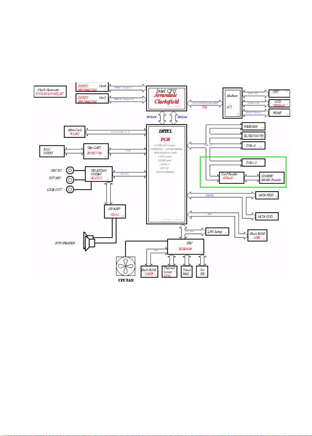
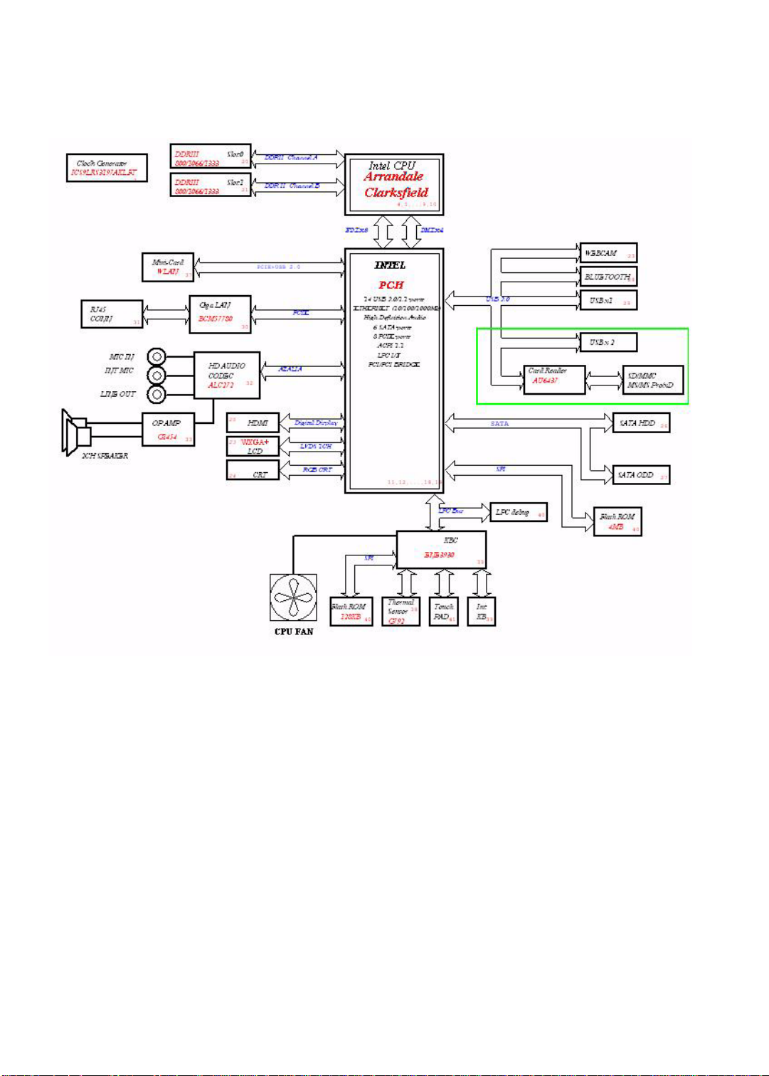
System block diagram . . . . . . . . . . . . . . . . . . . . . . . . . . . . . . . . . . . . . . . . 5
Block diagram – Discrete model . . . . . . . . . . . . . . . . . . . . . . . . . 5
Block diagram – UMA models . . . . . . . . . . . . . . . . . . . . . . . . . . 6
Hardware specifications . . . . . . . . . . . . . . . . . . . . . . . . . . . . . . . . . . . . . . 7
Processor . . . . . . . . . . . . . . . . . . . . . . . . . . . . . . . . . . . . . . . . . . . 7
Chipsets . . . . . . . . . . . . . . . . . . . . . . . . . . . . . . . . . . . . . . . . . . . . . 7
BIOS . . . . . . . . . . . . . . . . . . . . . . . . . . . . . . . . . . . . . . . . . . . . . . . 8
Memory . . . . . . . . . . . . . . . . . . . . . . . . . . . . . . . . . . . . . . . . . . . . . 8
Hard disk drive . . . . . . . . . . . . . . . . . . . . . . . . . . . . . . . . . . . . . . . 9
Optical disc drive . . . . . . . . . . . . . . . . . . . . . . . . . . . . . . . . . . . . 10
Card reader . . . . . . . . . . . . . . . . . . . . . . . . . . . . . . . . . . . . . . . . . 10
Ethernet . . . . . . . . . . . . . . . . . . . . . . . . . . . . . . . . . . . . . . . . . . . . 11
Wireless LAN . . . . . . . . . . . . . . . . . . . . . . . . . . . . . . . . . . . . . . . 11
Bluetooth . . . . . . . . . . . . . . . . . . . . . . . . . . . . . . . . . . . . . . . . . . . 11
Audio . . . . . . . . . . . . . . . . . . . . . . . . . . . . . . . . . . . . . . . . . . . . . . 12
LCD panel . . . . . . . . . . . . . . . . . . . . . . . . . . . . . . . . . . . . . . . . . . 12
Webcam . . . . . . . . . . . . . . . . . . . . . . . . . . . . . . . . . . . . . . . . . . . . 12
Keyboard . . . . . . . . . . . . . . . . . . . . . . . . . . . . . . . . . . . . . . . . . . . 13
Pointing device . . . . . . . . . . . . . . . . . . . . . . . . . . . . . . . . . . . . . . 13
Buttons/indicators/ports . . . . . . . . . . . . . . . . . . . . . . . . . . . . . . . . 13
USB . . . . . . . . . . . . . . . . . . . . . . . . . . . . . . . . . . . . . . . . . . . . . . . 14
AC adapter . . . . . . . . . . . . . . . . . . . . . . . . . . . . . . . . . . . . . . . . . 14
Battery . . . . . . . . . . . . . . . . . . . . . . . . . . . . . . . . . . . . . . . . . . . . 14
Chapter 2: System utilities . . . . . . . . . . . . . . . . . . . . . . . . . . . . . . . . . . . . . .15
BIOS setup utility . . . . . . . . . . . . . . . . . . . . . . . . . . . . . . . . . . . . . . . . . . 16
Navigating the BIOS setup utility . . . . . . . . . . . . . . . . . . . . . . . 17
BIOS setup utility menus . . . . . . . . . . . . . . . . . . . . . . . . . . . . . . 17
BIOS recovery . . . . . . . . . . . . . . . . . . . . . . . . . . . . . . . . . . . . . . . . . . . . . 26
Creating the Crisis Recovery disk . . . . . . . . . . . . . . . . . . . . . . . 26
Performing a BIOS recovery . . . . . . . . . . . . . . . . . . . . . . . . . . . 26
Running the Flash utility: . . . . . . . . . . . . . . . . . . . . . . . . . . . . . . 27
Clearing a BIOS password . . . . . . . . . . . . . . . . . . . . . . . . . . . . . . . . . . . 28
Unlocking the hard drive . . . . . . . . . . . . . . . . . . . . . . . . . . . . . . . . . . . . 29
i

Contents
Chapter 3: Replacing computer components . . . . . . . . . . . . . . . . . . . . . . . . 31
Preventing static electricity discharge . . . . . . . . . . . . . . . . . . . . . . . . . . 32
Tape . . . . . . . . . . . . . . . . . . . . . . . . . . . . . . . . . . . . . . . . . . . . . . . 32
Preparing the work space . . . . . . . . . . . . . . . . . . . . . . . . . . . . . . . . . . . . 33
Required tools . . . . . . . . . . . . . . . . . . . . . . . . . . . . . . . . . . . . . . . . . . . . . 34
Preparing the computer . . . . . . . . . . . . . . . . . . . . . . . . . . . . . . . . . . . . . . 35
Removing the battery . . . . . . . . . . . . . . . . . . . . . . . . . . . . . . . . . . . . . . . 36
Removing the bay cover . . . . . . . . . . . . . . . . . . . . . . . . . . . . . . . . . . . . . 37
Adding or replacing memory modules . . . . . . . . . . . . . . . . . . . . . . . . . . 38
Replacing the wireless card . . . . . . . . . . . . . . . . . . . . . . . . . . . . . . . . . . 39
Replacing the hard drive . . . . . . . . . . . . . . . . . . . . . . . . . . . . . . . . . . . . . 41
Replacing the optical drive . . . . . . . . . . . . . . . . . . . . . . . . . . . . . . . . . . . 43
Replacing the keyboard . . . . . . . . . . . . . . . . . . . . . . . . . . . . . . . . . . . . . . 45
Replacing the palm rest . . . . . . . . . . . . . . . . . . . . . . . . . . . . . . . . . . . . . . 47
Replacing the speakers . . . . . . . . . . . . . . . . . . . . . . . . . . . . . . . . . . . . . . 50
Replacing the power board . . . . . . . . . . . . . . . . . . . . . . . . . . . . . . . . . . . 52
Replacing the touchpad board . . . . . . . . . . . . . . . . . . . . . . . . . . . . . . . . . 54
Replacing the LCD panel assembly . . . . . . . . . . . . . . . . . . . . . . . . . . . . 56
Replacing the USB board . . . . . . . . . . . . . . . . . . . . . . . . . . . . . . . . . . . . 59
Replacing the Bluetooth module . . . . . . . . . . . . . . . . . . . . . . . . . . . . . . . 61
Replacing the system board . . . . . . . . . . . . . . . . . . . . . . . . . . . . . . . . . . 63
Replacing the cooling assembly . . . . . . . . . . . . . . . . . . . . . . . . . . . . . . . 67
Replacing the processor . . . . . . . . . . . . . . . . . . . . . . . . . . . . . . . . . . . . . 70
Replacing the DC power jack . . . . . . . . . . . . . . . . . . . . . . . . . . . . . . . . . 72
Replacing the LCD bezel . . . . . . . . . . . . . . . . . . . . . . . . . . . . . . . . . . . . 74
Replacing the LCD hinge caps . . . . . . . . . . . . . . . . . . . . . . . . . . . . . . . . 77
Replacing the computer lid magnet . . . . . . . . . . . . . . . . . . . . . . . . . . . . 78
Replacing the webcam . . . . . . . . . . . . . . . . . . . . . . . . . . . . . . . . . . . . . . 80
Replacing the LCD panel . . . . . . . . . . . . . . . . . . . . . . . . . . . . . . . . . . . . 82
Replacing the LCD hinge brackets . . . . . . . . . . . . . . . . . . . . . . . . . . . . . 86
Replacing the microphone . . . . . . . . . . . . . . . . . . . . . . . . . . . . . . . . . . . . 88
Replacing the WLAN antennas . . . . . . . . . . . . . . . . . . . . . . . . . . . . . . . 90
Replacing the LCD case . . . . . . . . . . . . . . . . . . . . . . . . . . . . . . . . . . . . . 93
Chapter 4: Troubleshooting . . . . . . . . . . . . . . . . . . . . . . . . . . . . . . . . . . . . .95
Diagnosing problems . . . . . . . . . . . . . . . . . . . . . . . . . . . . . . . . . . . . . . . . 96
System test procedures . . . . . . . . . . . . . . . . . . . . . . . . . . . . . . . . . . . . . . 97
Testing the optical drive . . . . . . . . . . . . . . . . . . . . . . . . . . . . . . . 97
Testing the keyboard or auxiliary input device . . . . . . . . . . . . . 97
Testing the memory . . . . . . . . . . . . . . . . . . . . . . . . . . . . . . . . . . . 98
Testing the power system . . . . . . . . . . . . . . . . . . . . . . . . . . . . . . 98
Testing the touchpad . . . . . . . . . . . . . . . . . . . . . . . . . . . . . . . . . . 99
Power-On Self-Test (POST) error message . . . . . . . . . . . . . . . . . . . . . 100
ii

www.packardbell.com
Index of error messages . . . . . . . . . . . . . . . . . . . . . . . . . . . . . . . . . . . . 101
Error codes . . . . . . . . . . . . . . . . . . . . . . . . . . . . . . . . . . . . . . . . 101
Error messages . . . . . . . . . . . . . . . . . . . . . . . . . . . . . . . . . . . . . 101
No-beep error messages . . . . . . . . . . . . . . . . . . . . . . . . . . . . . . 103
Phoenix BIOS beep codes . . . . . . . . . . . . . . . . . . . . . . . . . . . . . . . . . . 104
Symptom-to-FRU error messages . . . . . . . . . . . . . . . . . . . . . . . . . . . . 109
LCD . . . . . . . . . . . . . . . . . . . . . . . . . . . . . . . . . . . . . . . . . . . . . . 109
Power . . . . . . . . . . . . . . . . . . . . . . . . . . . . . . . . . . . . . . . . . . . . . 109
Memory . . . . . . . . . . . . . . . . . . . . . . . . . . . . . . . . . . . . . . . . . . . 110
Sound . . . . . . . . . . . . . . . . . . . . . . . . . . . . . . . . . . . . . . . . . . . . . 110
Power management . . . . . . . . . . . . . . . . . . . . . . . . . . . . . . . . . . 110
Devices . . . . . . . . . . . . . . . . . . . . . . . . . . . . . . . . . . . . . . . . . . . 111
Keyboard and touchpad . . . . . . . . . . . . . . . . . . . . . . . . . . . . . . 111
Intermittent problems . . . . . . . . . . . . . . . . . . . . . . . . . . . . . . . . . . . . . . 112
Undetermined problems . . . . . . . . . . . . . . . . . . . . . . . . . . . . . . . . . . . . 113
Chapter 5: Connector locations . . . . . . . . . . . . . . . . . . . . . . . . . . . . . . . . .115
System board layout . . . . . . . . . . . . . . . . . . . . . . . . . . . . . . . . . . . . . . . 116
Top view . . . . . . . . . . . . . . . . . . . . . . . . . . . . . . . . . . . . . . . . . . 116
Bottom view – Discrete model . . . . . . . . . . . . . . . . . . . . . . . . 117
Bottom view – UMA model . . . . . . . . . . . . . . . . . . . . . . . . . . 118
Chapter 6: FRU (Field-Replaceable Unit) list . . . . . . . . . . . . . . . . . . . . . .119
Introduction . . . . . . . . . . . . . . . . . . . . . . . . . . . . . . . . . . . . . . . . . . . . . . 120
Exploded diagram . . . . . . . . . . . . . . . . . . . . . . . . . . . . . . . . . . . . . . . . . 120
FRU list . . . . . . . . . . . . . . . . . . . . . . . . . . . . . . . . . . . . . . . . . . . . . . . . . 122
Appendix A: Test compatible components . . . . . . . . . . . . . . . . . . . . . . . 131
Introduction . . . . . . . . . . . . . . . . . . . . . . . . . . . . . . . . . . . . . . . . . . . . . . 132
Microsoft
®
Windows 7® Compatibility Test . . . . . . . . . . . . . . . . . . . 132
Appendix B: Online support information. . . . . . . . . . . . . . . . . . . . . . . . . 135
iii

Contents
iv

CHAPTER 1
System specifications
• Preface
• Features
• System block diagram
• Hardware specifications
1

Preface
Conventions
The following conventions are used in this manual:
Warning
Indicates a potential for personal injury.
Caution
Indicates a potential loss of data or damage to equipment.
Important
Indicates information that is important to know for the proper completion of
a procedure, choice of an option, or completing a task.
General information
Before using this information and the product it supports, read the following general
information.
This service guide provides you with all technical information relating to the basic
configuration decided for Acer’s global product offering. To better fit local market
requirements and enhance prod uct competitiveness, your regional office may have
decided to extend the functionality of a machine (such as add- on cards, modems,
or extra memory capabilities). These localized features are not covered in this
generic service guide. In such cases, contact your regional offices or the
responsible personnel/channel to provide you with further technical details.
When ordering FRU parts: Check the most up-to-date information available on
your regional web or channel. If, for whatever reason, a part number change is
made, it may not be noted in this printed service guide.
Acer-authorized Service Providers: Your Acer office may have a different part
number code to those given in the FRU list of this printed service guide . You must
use the list provided by your regional Acer office to order FRU parts for repair
and service of customer machines.
CHAPTER 1: System specifications
2

Features
www.packardbell.com
Platform
• Processor: Intel
• Core logic: Mobile Intel HM55 Express Chipset
®
Core™ i3, Intel® Core™ i5, or Intel® Core™ i7
System memory
• DDR3 SO-DIMM
• Data rate supported: 800/1066/1333 MT/s
• Maximum memory: 8 GB (using two 4 GB modules)
St orage subsystem
• Hard disk drive (HDD): 2.5” 9.5 mm industry standard SATA drive
• Optical disc drive (ODD): Blu-ray Disc™ Combo drive or DVD-Super Multi
double-layer drive
• 5-in-1 card reader supports Secure Digital™ (SD), MultiMediaCard (MMC),
Memory Stick
(xD)
®
(MS), Memory Stick PRO™ (MS PRO), xD-Picture Card™
Display and graphics
• 17.3" WXGA TFT LCD panel
• LED backlight
• VGA controller:
• Discrete models: ATI Mobility Radeon HD 5470 (Park XT) with 512 MB
DDR3 VRAM or ATI Mobility Radeon HD 5650 (Madison Pro) with 1 GB
DDR3 VRAM
• UMA models: Integrated in the Mobile Intel HM55 Express Chipset
• Supported resolutions
• UMA models: 800×600, 1024×768, 1280×720, 1280×768, 1600×900
• Discrete models: 800×600, 1024×768, 1 152×864, 1280×720, 1280×768,
1280×800, 1360×768, 1366×768, 1440×900, 1600×900
• Dual independent display support
• HDMI™ (High-Definition Multimedia Interface) with HDCP (High-bandwidth
Digital Content Protection) support
Audio
• Two built-in stereo speakers
• Built-in microphone on webcam
• Realtek ALC272 codec
• MS-Sound compatible
3

CHAPTER 1: System specifications
Communication
• Wired LAN: Onboard 10/100/1000 Ethernet support
• WLAN option: Mini Card wireless network adapter
• WPAN option: Bluetooth
®
2.1+EDR (Enhanced Data Rate)
• Integrated 1.3 MP webcam
Input devices
• GP8T flat keyboard
• Integrated numeric keypad
• Function keys (the F1 and F2 keys launch the data backup and WLAN
functions respectively)
• Volume control keys, cursor keys, Internet scroll keys, Social Networks
key, Windows
®
key, Application key
• Multi-touch touchpad with touchpad lock key
I/O ports
• USB (three)
• External display (VGA) port
• Headphone out
• Microphone in
• HDMI™ port with HDCP support
• Ethernet (RJ45)
• DC in jack for AC adapter
Security
• Kensington lock slot
• BIOS-based user, supervisor, and HDD passwords
Operating system
• Microsoft Windows XP
• Microsoft Vista
• Microsoft Windows 7 (Home Basic, Home Premium)
Physical specifications
• Dimensions (W × D × H): 414 × 275 × 27.1/34.3 mm
(16.30 × 10.83 × 1.07/1.35 in)
• Weight:
• Discrete models: 3.07 kg (6.77 lb)
• UMA models: 2.96 kg (6.53 lb)
Environmental requirement s
• Operating temperature: 5 to 35 °C (41 to 95 °F)
• Operating humidity (non-condensing): 20% to 80%
4
www.packardbell.com
System block diagram
Block diagram – Discrete models
5
CHAPTER 1: System specifications
Block diagram – UMA models
6

www.packardbell.com
Hardware specifications
Processor
Item Specification
Intel Core i3 Intel Core i5 Intel Core i7
330M 350M 430M 520M 540M 620M
Base frequency 2.13 GHz 2.26 GHz 2.26 GHz 2.40 GHz 2.53 GHz 2.66 GHz
Intel Turbo Boost
Technology
DMI 2.5 GT/s 2.5 GT/s 2.5 GT/s 2.5 GT/s 2.5 GT/s 2.5 GT/s
Intel Smart
cache
Package type 32 nm 32 nm 32 nm 32 nm 32 nm 32 nm
Thermal design
power
No No Yes,
2.533 GHz
3 MB 3 MB 3 MB 3 MB 3 MB 4 MB
35 W 35 W 35 W 35 W 35 W 35 W
Yes,
2.933 GHz
Yes,
3.066 GHz
Yes,
3.333 GHz
Chipsets
Item Specification
Core logic Mobile Intel HM55 Expres s Chipset
GPU (only for
Discrete models)
• ATI Mobility Radeon HD 5470 (Park XT), 512 MB DDR3 VRAM
• ATI Mobility Radeon HD 5650 (Madison Pro), 1G DDR3 VRAM
7

BIOS
Item Specification
BIOS chip Winbond W25X16
BIOS version v1.01
CHAPTER 1: System specifications
Supported protocols
Setup utility Phoenix SecureCore Setup Utility
• ACPI 1.0b/2.0/3.0 compliance
•PCI 2.2
• System/HDD password
• Security Control
• INT 13H Extensions
• PnP BIOS 1.0a SMBIOS 2.4
• BIOS Boot Specification
• Simple Boot Flag 1.0
• Boot block
• PCI Bus Power Management Interface Specification
• USB Specification 1.1/2.0
• IEEE 1394 1.0
• USB/1394 CD-ROM Boot Up support
• PC Card Standard 1995 (PCMCIA 3.0 Compliant Device)
•IrDA 1.0
• Intel AC97 CNR Specification
•WfM 2.0
•PXE 2.1
• Boot Integrity Service Application Program Interface (BIS) 1.0
• PC99a and Mobile PC2001 Compliant
BIOS password control Manually set
Memory
Item Specification
Controller Integrated in the Mobile Intel HM55 Express Chipset
Number of DIMM slot 2
Maximum memory 8 GB (using two 4 GB modules)
Data rate 800/1066/1333 MT/s
Supported capacities 1-, 2-, or 4 GB
DIMM type 204-pin DDR3 SO-DIMM
Supported brands Elpida, Hynix, Samsung, Nanya, Kingston
Population rule You can install memory modules in any co mbination as long as they match the above
specifications.
8

www.packardbell.com
Hard disk drive
Item Specification
Controller Integrated in the Mobile Intel HM55 Express Chipset
Form factor 2.5-inch 9.5 mm
Interface SATA 3.0
Supported capacities
160 GB • Seagate Momentus 5400.6 – ST9160314AS
• Toshiba MK1665GSX
• HGST Travelstar 5K500.B – HTS545016B9A300
• WD Scorpio Blue WD1600BEVT
250 GB • Seagate Momentus 5400.6 – ST9250315AS
• Toshiba MK2565GSX
• HGST Travelstar 5K500.B – HTS545025B9A300
• WD Scorpio Blue WD2500BEVT
320 GB • Seagate Momentus 5400.6 – ST9320325AS
• Toshiba MK3265GSX
• HGST Travelstar 5K500.B – HTS545032B9A300
• WD Scorpio Blue WD3200BEVT
500 GB • Seagate Momentus 5400.6 – ST9500325AS
• Toshiba MK5065GSX
• HGST Travelstar 5K500.B – HTS545050B9A300
• WD Scorpio Blue WD5000BEVT
640 GB • Toshiba MK6465GSX
• WD Scorpio Blue WD6400BEVT
9

CHAPTER 1: System specifications
Optical disc drive
Item Specification
Controller Integrated in the Mobile Intel HM55 Express Chipset
Type DVD-Super Multi double-layer drive or Blu-ray Disc™ Combo drive
Form factor Slim type
Interface SATA
Tray height (mm)) 12.7 mm
Write/read speed 8x
Supported models –
DVD-Super Multi
double-layer drive
Supported models –
Blu-ray Disc™
Combo drive
• HLDS GT31N / GT30N
• Panasonic UJ890A
• PLDS DS-8A4SH
• Sony Optiarc AD-7585H
• Toshiba Samsung TS-L633C
• HLDS CT21N
•PLDS DS-4E1S
• Sony Optiarc BC-5500H
Card reader
Item Specification
Controller Alcor Micro AU6437 (USB 2.0 Single-LUN Flash Card Reader Controller)
Card compatibility MMC, SD, xD, MS, and MS PRO
10

Ethernet
Item Specification
www.packardbell.com
Controller
LAN protocol 10/100/1000 Mbps
LAN connector type RJ-45
Broadcom NetLink® Gigabit Ethernet Controller (BCM57780)
Wireless LAN
Item Specification
Model • Atheros Wireless LAN HB93 2x2 BGN (HM) / HB95BG (HM)
• Broadcom Wireless LAN 43225 2x2 BGN (HM)
• Intel Wireless LAN 112BN.HMWG / INT1000HBG / 622AN.HMWG
• Lite-On Wireless LAN HB93 2x2 BGN (HM) WN6602AH / HB97 2x2 BGN (HM)
WN6603AH / BGN WN6603LH(2x2 BGN)
• Realtek RTL8191SE
• QMI Wireless LAN HB93 2x2 BGN (HM) EM306
• WNC Wireless HB93 2x2 BGN (HM)
Form factor PCIe Mini Card
IEEE WLAN standard • IEEE 802.11a
• IEEE 802.11b
• IEEE 802.11g
• IEEE 802.1 1 Draft-N
Bluetooth
Item Specification
Model • Broadcom BCM2046 (Single-Chip Bluetooth EDR HCI)
• Atheros AR3011 (Single-Chip Bluetooth 2.1 + EDR)
Version Bluetooth 2.1 + EDR
11

CHAPTER 1: System specifications
Audio
Item Specification
Controller Realtek ALC272X (HD Audio / Azalia)
Features • Two built-in stereo speakers
• Built-in microphone on webcam
• MS-Sound compatible
LCD panel
Item Specification
Screen size
(diagonal, inch)
Type Wide XGA
Backlight LED
Interface LVDS
Brightness (nits) 220
Aspect ratio 16:9
Response time (ms) 8
Optical coating Anti-glare
Supported models • AUO B173RW01
17.3
• CMO N173O6-L02
• LG LP173WD1-TLA3
• Samsung LTN173KT01-A01
Webcam
Item Specification
Resolution 1.3 MP
Supported models • Chicony CH9665SN
• Suyin SY9665SN
• Lite-On LT9665AL / LT6AASP
12

www.packardbell.com
Keyboard
Item Specification
Controller Winbond KBC773L
Brand Darfon
Features • Integrated numeric keypad
• Function keys (the F1 and F2 keys launch the data backup and WLAN functions
respectively)
• Volume control keys, cursor keys, Internet scroll key s, Social Networks key, Windows
key, Application key
Pointing device
Item Specification
®
Model
Type Multi-touch touchpad with touchpad lock key
Buttons Left/Right
• Synaptics TM00540-005 Touchpad
• ALPS KGDFF0038A Touchpad
Buttons/indicators/ports
Item Specification
Buttons
Indicators
Ports
• Power button
• Launch buttons for data backup and WLAN functions (F1 and F2 keys respectively)
• Hard drive activity
• WLAN status
• Power status
• Battery charge
• USB (three)
• External display (VGA) port
• Headphone out
• Microphone in
• HDMI™ port with HDCP support
• Ethernet (RJ45)
• DC in jack for AC adapter
13

CHAPTER 1: System specifications
USB
Item Specification
Chipset Mobile Intel HM55 Express Chipset
USB compliancy level 2.0
OHCI USB 1.1 and USB 2.0 host controller
Number of USB ports 3
Location
• Two on the left side
• Two on the right side
AC adapter
Item Specification
For models with Intel-integrated or ATI Mobility Radeon HD 5470 (Park XT) graphics controller
19 V, 65 W • Delta ADP-65JH DB
• Lite-On PA-1650-22AC
• Hipro HP-A0652R3B
For models with ATI Mobility Radeon HD 5650 (Madison Pro) graphics controller
19 V, 90 W • Delta ADP-90CD DB
• Lite-On PA-1900-34AR
• Hipro HP-A0904A3
Battery
Item Specification
Capacity 4400 mAh
Pack capacity 6 cells
Type Lithium-ion, 3S2P
Charge time
(charge-in-use)
Supported brands Panasonic, Samsung, Sanyo, Simplo, Sony
1.5~2 hours for 0~80%, 3~3.5 hours for 0~99%, 3.5~4 hours for 0~100%
14

CHAPTER2
• BIOS setup utility
• BIOS recovery
• Clearing a BIOS password
• Unlocking the hard drive
System utilities
15
CHAPTER 2: System utilities
BIOS setup utility
The BIOS setup utility is a hardware configuration program built into the notebook’s
BIOS (Basic Input/Output System). The notebook was shipped already properly
configured and optimized. However , if the user encounters configura tion problems,
you may need to run Setup.
To run the BIOS Setup Utility:
1 Turn on the notebook.
If the computer is already turned on, save your data and close all open
applications, then restart the computer.
2 Press F2 when the Press <F2> to enter Setup prompt appears on the bottom
of the screen.
Use the left and right arrow keys to move between selections on the menu
bar.
16

www.packardbell.com
Navigating the BIOS setup utility
Use the keys listed in the legend bar on the bottom of the Setup screen to work
your way through the various menu and submenu screens.
To use the BIOS setup utility:
• To choose a menu, use the left and right arrow keys.
• To choose an item, use the up and down arrow keys.
• To change the value of a parameter, press F5 or F6.
• A plus sign (+) indicates the item has sub-items. Press ENTER to expand this
item.
• To load default settings, press F9.
• To save changes made and close the ut ility, press F10.
• Press ESC while you are in any of the menu screen to display the Exit menu.
Important
• You can change the value of a parameter if it is enclosed in
square brackets.
• Navigation keys for a particular menu are shown on the bottom
of the screen. Help for parameters are found in the Item Specific
Help part of the screen. Read this information carefully when
making changes to parameter values.
• The screenshots used in this section are for illustration only. The
values displayed may not be the same as those in your computer.
BIOS setup utility menus
The Setup utility has five menus for configuring the various system functions.
These include: Information, Main, Security, Boot, and Exit.
Important
• The screenshots used in this section are for illustration only. The
values displayed may not be the same as those in your computer.
Actual screen information varies by model, installed features, and
location.
• In the descriptive table following each of the screenshot, settings
in boldface are the default settings.
17
CHAPTER 2: System utilities
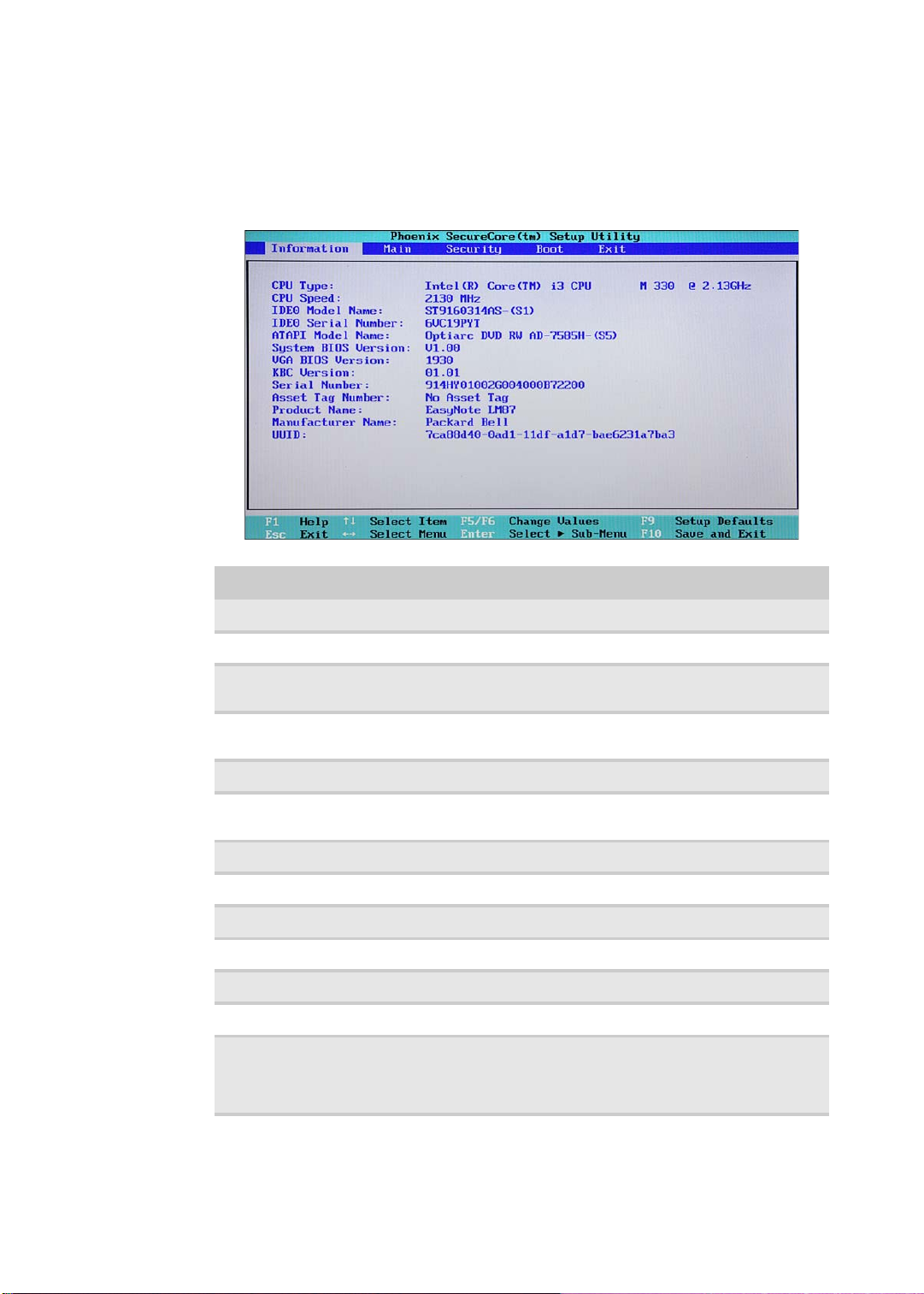
Information
The Information menu displays a summary of your computer hardware information.
These information are necessary for troubleshooting and may be required when
asking for technical support.
Parameter Description
CPU Type Displays the processor model and speed.
CPU Speed Displays the processor speed.
IDE0 Model Name Displays the model name of the hard drive installed on the
IDE0 Serial Number Displays the serial number of the hard drive installed on the
ATAPI Model Name Displays the model name of the installed optical drive.
System BIOS
Version
VGA BIOS Version Displays the VGA firmware version.
KBC Version Displays the keyboard controller version.
Serial Number Displays the system serial number.
Asset Tag Number Displays the system asset tag number
Product Name Displays the official model name of the computer.
Manufacturer Name Displays the name of the compute r manufacturer.
UUID Number Displays the computer’s UUID (universally unique identifier).
primary IDE master.
primary IDE master.
Displays system BIOS version.
UUID is an identifier standard used in software construction,
standardized by the Open Software Foundation (OSF) as part
of the Distributed Computing Environment (DCE).
18
www.packardbell.com
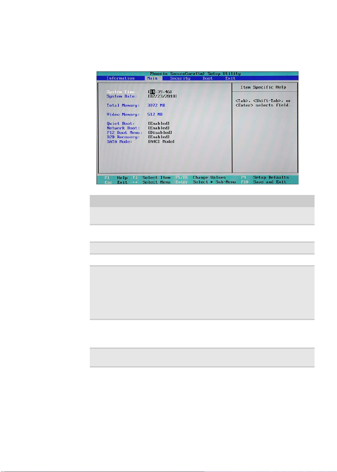
Main
Use the Main menu to set the system time and date, and other basic options.
Parameter Description Format/Options
System Time Displays the system time. The time is
expressed in a 24-hour format.
System Date Displays the system date. MM/DD/YYYY
Total Memory Disp lays the size of system memory detected during boot-up.
Video Memory Displays the size of video memory detected during boot-up.
Quiet Boot Enables or disables the Quiet Boot
function.
When enabled, BIOS setup is in graphical
mode and displays only the computer
brand logo during POST and while booting.
When disabled, BIOS setup is in
conventional text mode and displays the
system Summary Screen.
Network Boot When e nabled, a remote host with
appropriate boot image can boot this
computer. (only works with an Ethernet
device.)
F12 Boot Menu Enables or disables the Boot menu during
POST.
HH:MM:SS
(hour:minute:second)
(month/day/year)
Disabled
Enabled
Disabled
Enabled
Disabled
Enabled
19
CHAPTER 2: System utilities
Parameter Description Format/Options
D2D Recovery Enables or disables the D2D Recovery
function. This function allows the user to
create a hidden partition on the hard drive
to store the operation system. User can
then use this partition to restore the system
to factory defaults by pressing the Alt+F10
keys during system boot-up.
SATA Mode Select the SA T A controller operating mode.
When set to AHCI (Advanced Host
Controller Interface), the SATA controller
enables its AHCI and RAID features when
the computer boots up.
When set to IDE, the SATA controller
disables its AHCI and RAID functions when
the computer boots up.
Note: If you do not intend to use the AHCI
or RAID features set this parameter to IDE
to speed up the boot-up time.
Disabled
Enabled
AHCI
IDE
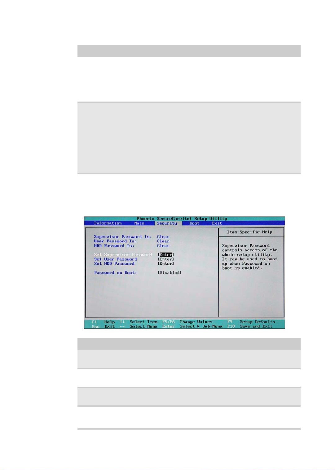
Security
Use the Security menu option to set system passwords to protect your computer
from unauthorized use.
.
20
Parameter Description Option
Supervisor
Password Is
User Password Is Displays the user password status. Clear
HDD Password Is Displays the hard drive password status. Clear
Set Supervisor
Password
Displays the supervisor password status. Clear
Set
Set
Set
Press Enter to set a supervisor password. W hen set, this password
will allow the user to access and change all settings in the Setup
Utility.
www.packardbell.com
Parameter Description Option
Set User Password Press Enter to set a user password. When set, this password will
Set HDD
Password
Password on Boot Referred to as the power-on password. When
Caution
When you are prompted to enter a password, you have three tries
before the system halts. Don’t forget your password.
restrict a user’s access to the Setup menus. Only the following
menus will be accessible:
• System Time and System Date
• All Exit menu options excluding Load Setup Defaults
Note: A supervisor password must first be set before creating a
user password.
If Password on Boot is enabled, the user must enter the user
password each time the notebook is turned on or wakes from
Sleep.
Press Enter to set password for accessi ng the hard disk drive
(HDD) password. It will be required during boot-up or when waking
from hibernation mode.
enabled, the user or supervisor password will be
required to boot up the system.
Note: A supe rvisor password must first be set
before creating a user password.
Disabled
Enabled
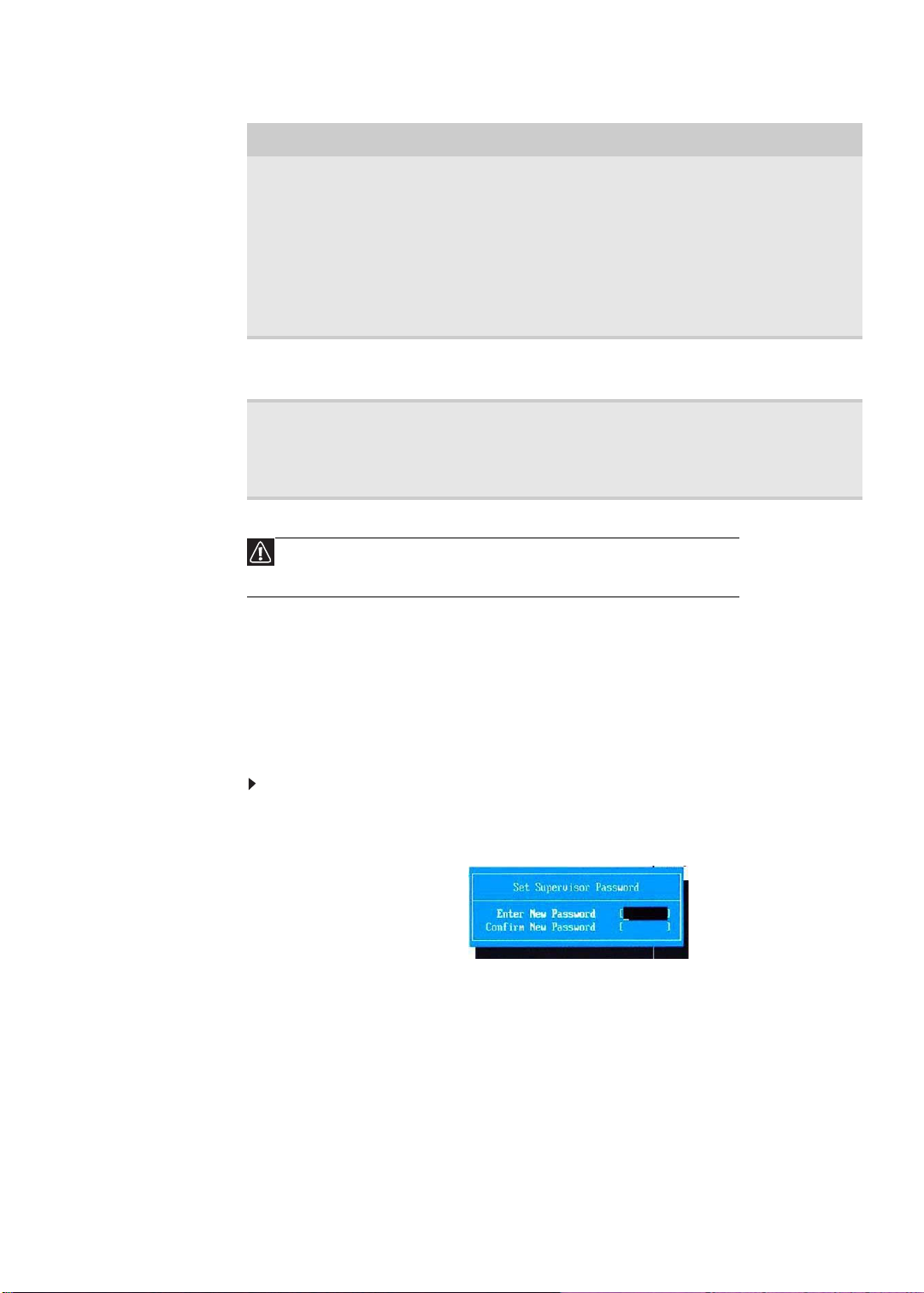
Setting a password
Note the following reminders before you define a system password:
• The maximum length of password contains 8 alphanumeric characters.
• System passwords are case-insensitive.
• When typing the password, only shaded blocks representing each typed
character are visible.
To set a supervisor password:
1 Press or to highlight Set Supervisor Password, then press Enter.
The Set Supervisor Passw ord box opens.
2 Type a password, then press Enter.
21
CHAPTER 2: System utilities
3 Retype the password to verify the first entr y, then press Enter.
You will be prompted to save the new password.
4 Press Enter.
5 Press F10 to save the password and close the Setup Utility or you can
proceed to setting a user password.
To set a user password:
1 Press or to highlight Set User Password, then press Enter.
The Set User Passw ord box opens.
2 Type a password, then press Enter.
3 Retype the password to verify the first entr y, then press Enter.
You will be prompted to save the new password.
4 Press Enter.
5 Press F10 to save the password and close the Setup Utility.
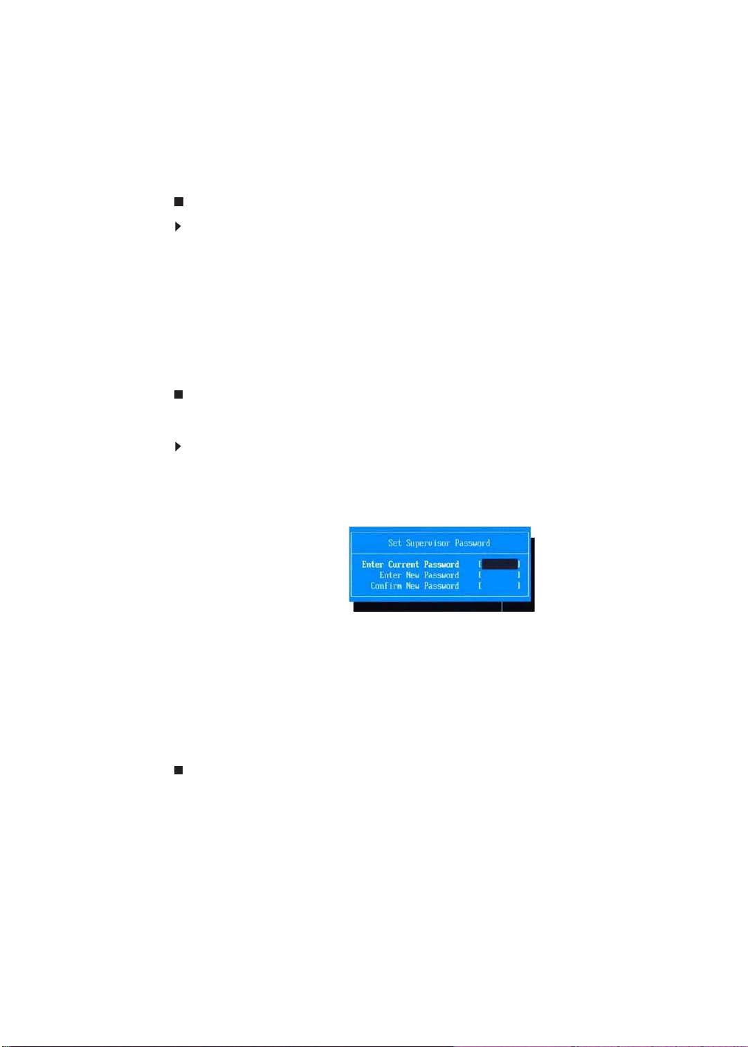
Changing a password
To change a password:
1 Press or to highlight the Set Supervisor Password or Set User Password
field, then press Enter.
The Set Supervisor Password or Set User Password box opens.
22
2 Type the current password, then press Enter.
3 Type a new password, then press Enter.
4 Retype the new password to verify the first entry, then press Enter.
You will be prompted to save the new password.
5 Press Enter.
6 Press F10 to save the password and close the Setup Utility or you can
proceed to setting a user password.

www.packardbell.com
Removing a password
To remove a password:
1 Press or to highlight the Set Supervisor Password or Set User Password
field, then press Enter.
The Set Supervisor Passw ord or Set User Password box opens.
2 Type the current password, then press Enter.
3 Press Enter twice without entering anything in the new and confirm password
fields.
You will be prompted to confirm the password removal.
4 Press Enter.
5 Press F10 to save the password and close the Setup Utility or you can
proceed to setting a user password.
Resetting a password
If you have forgotten the user password, the computer will continue to function
normally but you will have limited access to the Setup utility.
If you have enabled the Password on Boot field and you forget the supervisor
password, you will not be able to boot up the computer. The same thing applies
if you forget the HDD password.
To clear a lost BIOS password (user or supervisor password) you need to short
the clear password hardware gap located on the system board. Go to page 28
for instructions.
To regain access to your computer if you lose the HDD password, you need to
generate a master password and unlock your hard drive. Go to page 29 for
instructions.
23
CHAPTER 2: System utilities
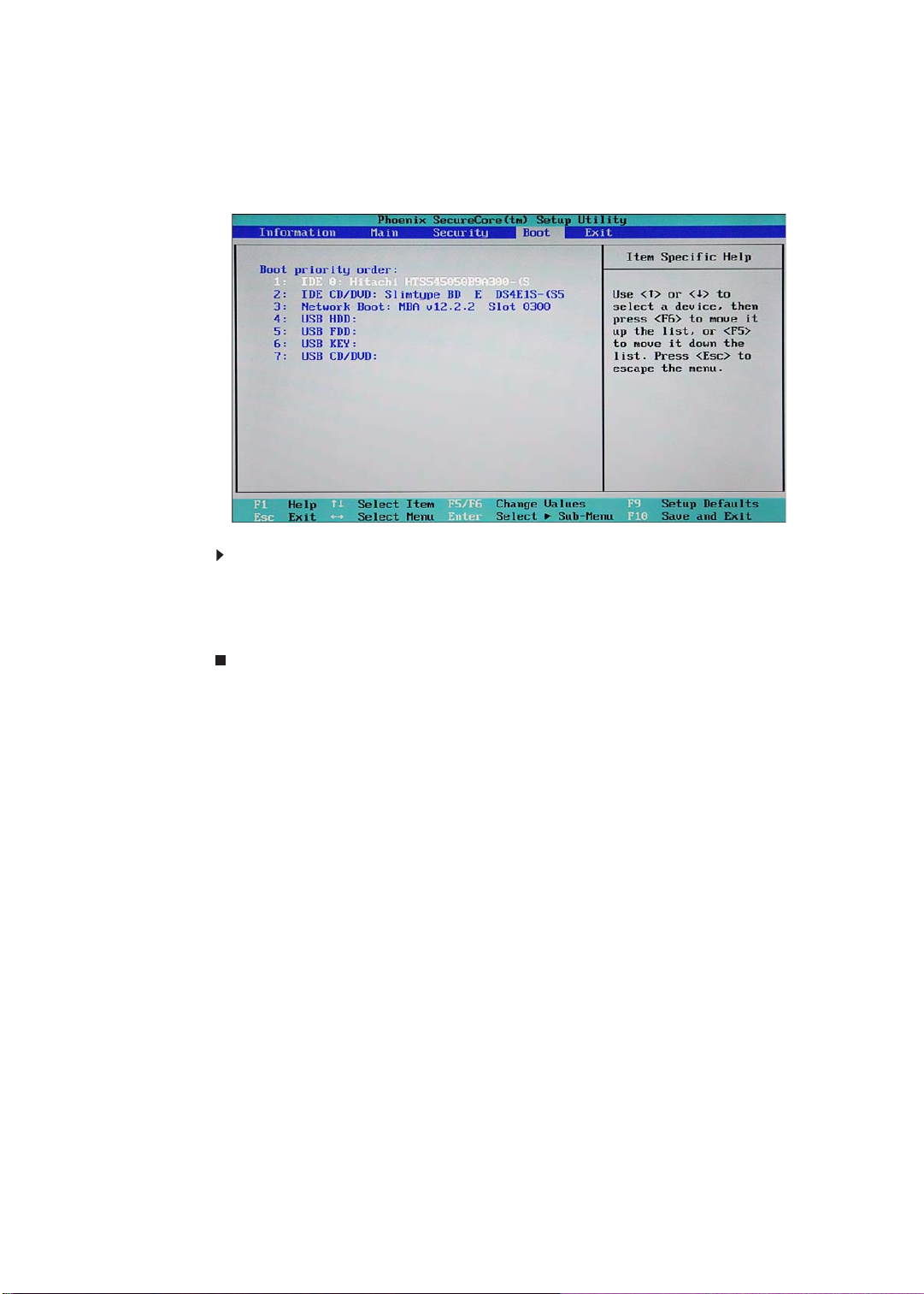
Boot
Use the Boot menu to set the preferred drive sequence in which the Setup utility
attempts to boot the operating system.
To set boot drive sequence:
1 Press or to highlight a bootable device.
2 Press F5 or F6 to move the selected device up or down the boot sequence.
3 Press F10 to save the changes you made and close the Setup utility.
24
 Loading...