

Page 1
Jupiter Disassembly Manual version 1.0
--------------------------------------------------------------------------------------------------
-------------------------------------------------------------------------------------------------- [ Page 1 of 11 ]
Product Support Consumer for NEC Computers International B.V. © 2004
JUPITER Disassembly Manual
Version Modifications Author Date
0.1
Typed text version based on disassembly notes Juan M. Calviño
Alonso
26/11/04
0.2
Draft version + photos
D.Egberts 26/11/04
1.0 Added ‘password clear’ and ‘jumpers/dipswitch’ section D. Egberts 29/11/04
Page 2
Jupiter Disassembly Manual version 1.0
--------------------------------------------------------------------------------------------------
-------------------------------------------------------------------------------------------------- [ Page 2 of 11 ]
Product Support Consumer for NEC Computers International B.V. © 2004
Disassembly Instructions
1. Remove battery
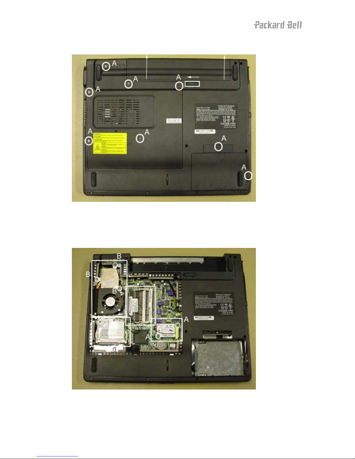
2. Remove HDD cover (1 x screw A)
3. Remove HDD
4. Remove USB cover (1 x screw A)
5. Remove mobo cover (6 x screw A)
6. Remove memory from memory slots (2 x)
7. Remove WiFi MiniPCI card from slot
8. Disconnect antennas
9. Remove screws (2 x screw A) on modem
Page 3
Jupiter Disassembly Manual version 1.0
--------------------------------------------------------------------------------------------------
-------------------------------------------------------------------------------------------------- [ Page 3 of 11 ]
Product Support Consumer for NEC Computers International B.V. © 2004
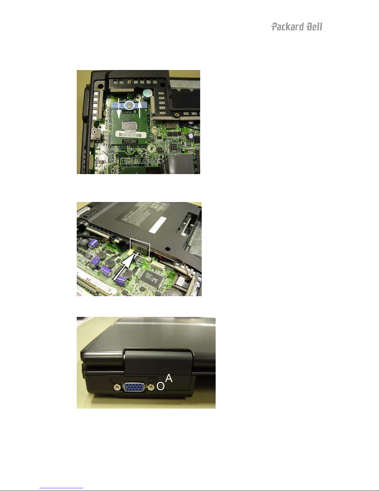
10. Disconnect cable
11. Disconnect CPU fan
12. Remove heat sink screws (3 x screw B)
13. Remove heat sink
14. Unlock CPU
15. Remove CPU
16. Push out optical drive
17. Remove screw (1 x screw A) from the hinge cover
Page 4
Jupiter Disassembly Manual version 1.0
--------------------------------------------------------------------------------------------------
-------------------------------------------------------------------------------------------------- [ Page 4 of 11 ]
Product Support Consumer for NEC Computers International B.V. © 2004
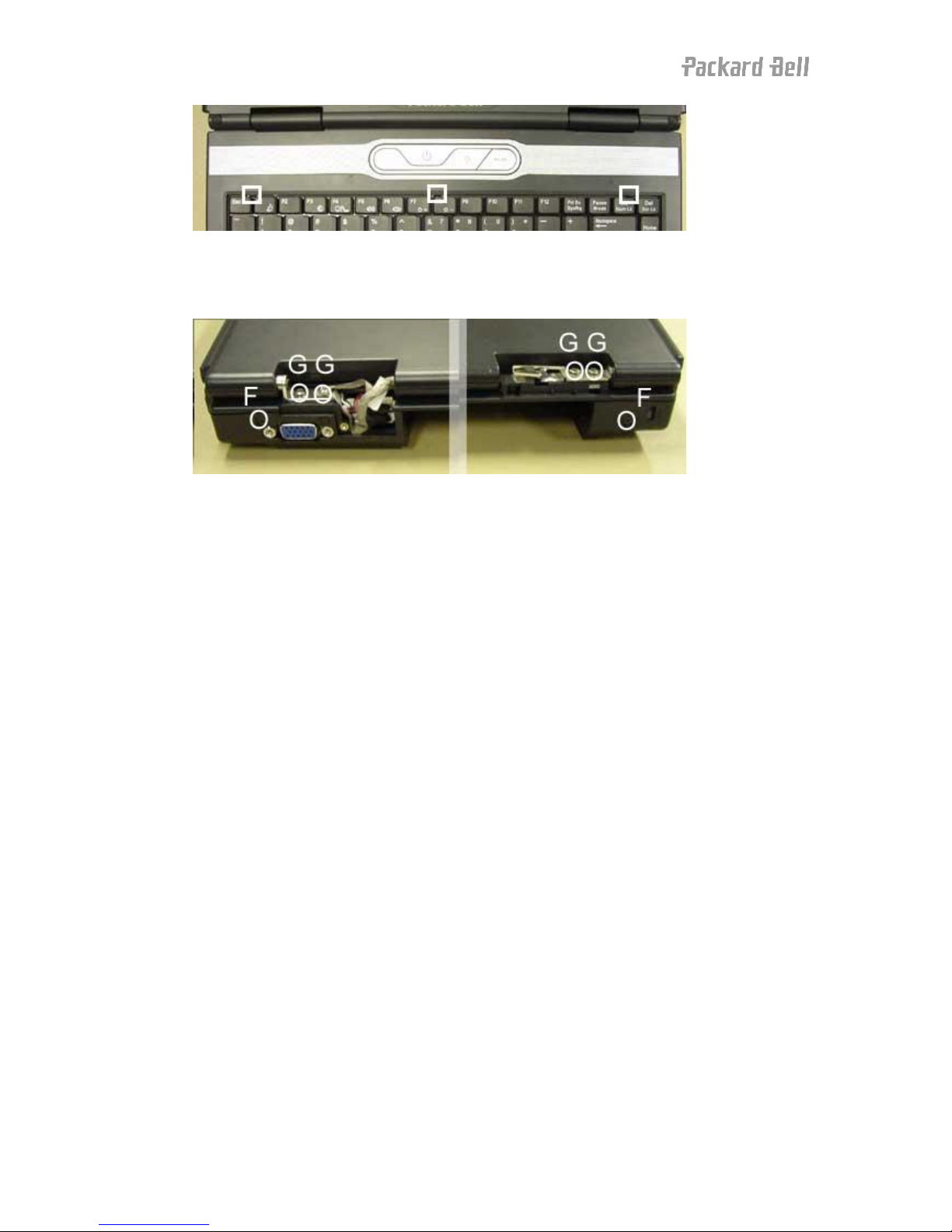
18. Push up the 3 keyboard locks, lift keyboard up
19. Disconnect keyboard flat cable
20. Push up the hinge covers back and up, and remove them
21. Remove screws (2 x screw F) on the rear of the unit
22. Disconnect 2 LCD connectors
23. Open LCD completely
24. Remove left hinge screws (2 x screw G) & wireless antenna
25. Remove right hinge screws (2 x screw G) & earth cable
Page 5

Jupiter Disassembly Manual version 1.0
--------------------------------------------------------------------------------------------------
-------------------------------------------------------------------------------------------------- [ Page 5 of 11 ]
Product Support Consumer for NEC Computers International B.V. © 2004
26. Remove bottom base cover screws (12 x screw D, 2 x screw C, 3 x screw A, 3 x
screw E)
27. Lift up bottom base cover
28. Disconnect USB internal cable
Page 6

Jupiter Disassembly Manual version 1.0
--------------------------------------------------------------------------------------------------
-------------------------------------------------------------------------------------------------- [ Page 6 of 11 ]
Product Support Consumer for NEC Computers International B.V. © 2004
29. Remove screw (1 x screw A) from USB HUB board
30. Remove USB HUB board & cable from bottom base assy
31. Remove hex bolt (2 x screw H) from VGA port
Page 7

Jupiter Disassembly Manual version 1.0
--------------------------------------------------------------------------------------------------
-------------------------------------------------------------------------------------------------- [ Page 7 of 11 ]
Product Support Consumer for NEC Computers International B.V. © 2004
32. Remove hex bolt (1 x screw J) from main board
33. Remove hex bolt (1 x screw L) from main board
34. Disconnect the modem/LAN board connector cable from main board
35. Remove screw (1 x screw F) from main board
36. Disconnect the hard disk connector board
37. Disconnect touchpad button board flat cable
Page 8

Jupiter Disassembly Manual version 1.0
--------------------------------------------------------------------------------------------------
-------------------------------------------------------------------------------------------------- [ Page 8 of 11 ]
Product Support Consumer for NEC Computers International B.V. © 2004
38. Lift main board up, but disconnect speaker assy cable before removing it
39. Remove WiFi cable
40. Remove screw (1 x screw A) from speaker assembly (left side on photo)
41. Remove port cover from right speaker assembly
Page 9

Jupiter Disassembly Manual version 1.0
--------------------------------------------------------------------------------------------------
-------------------------------------------------------------------------------------------------- [ Page 9 of 11 ]
Product Support Consumer for NEC Computers International B.V. © 2004
42. Remove screw (1 x screw M) from left speaker assembly (right side on photo)
43. Disconnect touchpad cable from touchpad
44. Push out touchpad to disconnect it from top cover
45. Remove touchpad cable from touchpad
46. Remove screws from touchpad button board (3 x screw A)
47. Disconnect flat cable from touchpad button board
48. Remove screws (3 x screw K) of button board
49. Remove button board
50. Disconnect button board flat cable
(Re-)assembly Notes
Battery Connector Cover (put it back on when re-assembling)
Page 10

Jupiter Disassembly Manual version 1.0
--------------------------------------------------------------------------------------------------
-------------------------------------------------------------------------------------------------- [ Page 10 of 11
]
Product Support Consumer for NEC Computers International B.V. © 2004
Wifi Button & Switch: MAKE SURE THEY ARE ALINGED PROPERLY!
Remove the HDD assembly like this:
Step 1. Use the HDD mylar to pull the HDD out of the connector (to the right)
Step 2. Lift up the HDD assembly out of the HDD bay.
Page 11

Jupiter Disassembly Manual version 1.0
--------------------------------------------------------------------------------------------------
-------------------------------------------------------------------------------------------------- [ Page 11 of 11
]
Product Support Consumer for NEC Computers International B.V. © 2004
Clear Password
Password clearing can be done by removing the main battery and CMOS battery at the same
time for at least 1 minute.
Jumpers / Di pswitches
This platform does not have jumpers or dipswitches.
 Loading...