

Page 1
EasyNote T5 series Disassembly Manual
Click to buy NOW!
P
D
F
-
X
C
H
A
N
G
E
w
w
w
.
d
o
c
u
-
t
r
a
c
k
.
c
o
m
Click to buy NOW!
P
D
F
-
X
C
H
A
N
G
E
w
w
w
.
d
o
c
u
-
t
r
a
c
k
.
c
o
m
NEC Computers Internationa l B.V.
EasyNote T5 series
Disassembly M anual
Revision: 2.0
Date: September 2003
For Packard Bell
A division of NEC Computers International B.V.
Page 2

Table of contents
Click to buy NOW!
P
D
F
-
X
C
H
A
N
G
E
w
w
w
.
d
o
c
u
-
t
r
a
c
k
.
c
o
m
Click to buy NOW!
P
D
F
-
X
C
H
A
N
G
E
w
w
w
.
d
o
c
u
-
t
r
a
c
k
.
c
o
m
Overview........................................................................................................................................................................3
Technician Notes ..........................................................................................................................................................3
Disassembly Instructions..............................................................................................................................................3
Reassembly Instructions ..............................................................................................................................................3
Required Tools..............................................................................................................................................................3
Hazardous Voltage .......................................................................................................................................................3
Avoid Electrostatic Discharge ......................................................................................................................................3
Power Supply Unit ........................................................................................................................................................3
Removing the Battery...................................................................................................................................................3
Removing the Hard Disk Drive.....................................................................................................................................3
Removing the MDC Modem Module ...........................................................................................................................3
Removing the Keyboard Cover....................................................................................................................................3
Removing Keyboard .....................................................................................................................................................3
Removing the Optical drive & Heat plate....................................................................................................................3
Removing the Memory Module....................................................................................................................................3
Removing the Wireless Module...................................................................................................................................3
Removing Heat Sink & CPU........................................................................................................................................3
Removing the LCD Module..........................................................................................................................................3
Removing the LCD Penal.............................................................................................................................................3
Removing the Top Cover .............................................................................................................................................3
Removing the Touch Pad.............................................................................................................................................3
Removing the DC/DC Board........................................................................................................................................3
Removing the Main Board............................................................................................................................................3
DIP Switch Setting........................................................................................................................................................3
Screws ...........................................................................................................................................................................3
Notice.............................................................................................................................................................................3
Packard Bell EasyNot e T5 Disassemb ly Manual
Page 2
Page 3

Overview
Click to buy NOW!
P
D
F
-
X
C
H
A
N
G
E
w
w
w
.
d
o
c
u
-
t
r
a
c
k
.
c
o
m
Click to buy NOW!
P
D
F
-
X
C
H
A
N
G
E
w
w
w
.
d
o
c
u
-
t
r
a
c
k
.
c
o
m
This documen t contain s step-b y-step d isa ssem bl y instruc tion s for the EasyNote T5 chassis. The instru c tio ns are
illustrated whe re necessar y with images of the part that is being removed or disassembled. Furthe rmore , the screws
that are removed are shown next to the image of the parts themselves.
Packard Bell reser ves th e rig ht to make changes to the EasyNote T5 chassis without no tic e.
Technician Notes
Only technicians authorize d by NEC Computers Internationa l B.V. should attem pt to repair this equipmen t. All
troubleshooting and repair procedures are detailed to allo w only subassembly/modu le level repair. Because of the
complexity of the individual boards and subassemblies , no one should attemp t to make repairs at the component
level or to make modification s to any printed wiring board. Improper repa irs can create a safety hazard. Any
indica tion of componen t replacem en t or printed wiring board mod ifica tion s may void any warranty or exchange
allowances.
Disassembly Instructions
When disassembl ing the system unit, follow these general rules:
n Do not disassemble the system into parts that are smaller than those specified in the instruc tions.
n Label all remo ved connectors. Note where the connec tor goes and in what position it was installed.
n Turn off the power and disconnect all power and all options.
Reassembly Instructions
Reassembly is the reverse of the disassembly process. Use care to ensure that all ca bles and screws are returned
to their proper position s. Check that no tools or any loose parts have been left inside the chassis. Check that
everything is properl y installed and tightened.
Required Tools
All disasse mbly proced ures can be performed using the followi ng tools:
n PH 0x60 Philips screwdriver
n PH 0x40 Philips screwdriver
n 4.0 x 60 Flat screwdri v er
n 2.0 x 30 Flat screwdri v er
n SW5,0 Spacer screwdriver
n Small tweez ers
Packard Bell EasyNot e T5 Disassemb ly Manual
Page 3
Page 4

Hazardous Voltage
Click to buy NOW!
P
D
F
-
X
C
H
A
N
G
E
w
w
w
.
d
o
c
u
-
t
r
a
c
k
.
c
o
m
Click to buy NOW!
P
D
F
-
X
C
H
A
N
G
E
w
w
w
.
d
o
c
u
-
t
r
a
c
k
.
c
o
m
There is hazardou s voltage presen t inside the computer
when it is connected to an AC supply, even when the
computer’ s power switch is off. Exposure to hazardous
voltage could cause personal injury. To avoid risk of injury,
contact an Authorized Service Provider for proper
(un)installa tion of optional hardware devices.
Avoid Electrostatic Discharge
Electr osta tic electr icity can easil y damage circu it cards and
integrated c ircuits (ICs). To reduce risk o f damage, store
them in protective packaging wheneve r they are not
installed in your system.
Add-in cards can be extremely sensitive to ESD and always
require careful handling. After removing the card from the
computer, place the card flat on a grounded, static-free
surface, component-side up. Use a conductive foam pad if
available, but not the card wrapper. Do not slide the card
over any surface.
WARNING
Ensure that the computer is disconnected from
its power source and f r om al l
telecommun ications links, networks, or modem
lines whenev er the chassi s cover is removed.
Do not operate the computer with the cover
removed.
AVERTISSEMENT
Assurez-vous que le système est débranché de
son alimentation ainsi que de toute s les
liais ons de téléco mmuni cation, des réseaux , et
des lignes de modem avant d’enle ve r le capo t.
Ne pas utiliser le système quand le capot est
enlevé.
WARNUNG
Das System darf weder an eine Stromquelle
angeschlossen sein noch eine Verbindung mit
einer Telekommun ikationseinrich tung, einem
Netzwerk oder einer Modem-Leitung haben,
wenn die Gehäuseabdeckun g entfernt wird.
Nehmen S ie das System nicht ohne die
Abdeckung in Betrieb.
Before you install or remove memory modules, video
memory, di sk driv es, circui t cards or other devices, pr otect
them from stati c electricity . To do so, make sure your
computer’ s power switch is OFF. Then , unplug the
computer’s AC power co rd. Befo re picking up the device you
(un)install , you should wear an anti-static wrist wrap
(available at electronic supp l y stores). Be sure to connect
the wrist wrap to an unpainted metal por tion of the computer
chass is. As an alternative, you can dissipa te elec tros ta tic
build-up by touching an unpainted metal por tion of the
computer cha ss is with one hand . Then tou ch the devic e you
are (un)installing with the other hand, and maintain
continuous contac t with it until it is (un)installed in the
computer.
Power Supply Unit
Under no circumstances shoul d you attempt to disassemble
the power supply. The power supply con tains no userserviceable parts. Inside the power supply are hazardous
voltages tha t can cause serious personal injury. Always
return a defective power supply to your dealer.
ADVERTENCIA
Asegúrese de que cada vez qu e se quite la
cubierta del chasis, el sistema haya sido
desconectado de la red de alimentación y de
todos lo enlaces de telecomunicaciones, de red
y de líneas de módem. No ponga en
funcionam iento el sistema mientras la cubierta
esté quitada.
WAARSCHUWING
Zorg er voor dat alle verbindingen van en naar
de compu ter (stroom, modem netwerk, etc)
verbroken worden voordat de behuizing
geopend word t. Zet de computer nooit aan als
de behuizing geopend is.
AVVERTENZA
Prima di rim u overe il cop erch io d el tela io,
assicu ra rsi che il sistema sia scolle gat o
dall’al imen tazione, da tutti i collegam enti di
comun icazione, re ti o linee d i modem . Non
avviare il sistema senza aver prima messo a
posto il coperchio
Packard Bell EasyNot e T5 Disassemb ly Manual
Page 4
Page 5
Removing the Battery
Click to buy NOW!
P
D
F
-
X
C
H
A
N
G
E
w
w
w
.
d
o
c
u
-
t
r
a
c
k
.
c
o
m
Click to buy NOW!
P
D
F
-
X
C
H
A
N
G
E
w
w
w
.
d
o
c
u
-
t
r
a
c
k
.
c
o
m
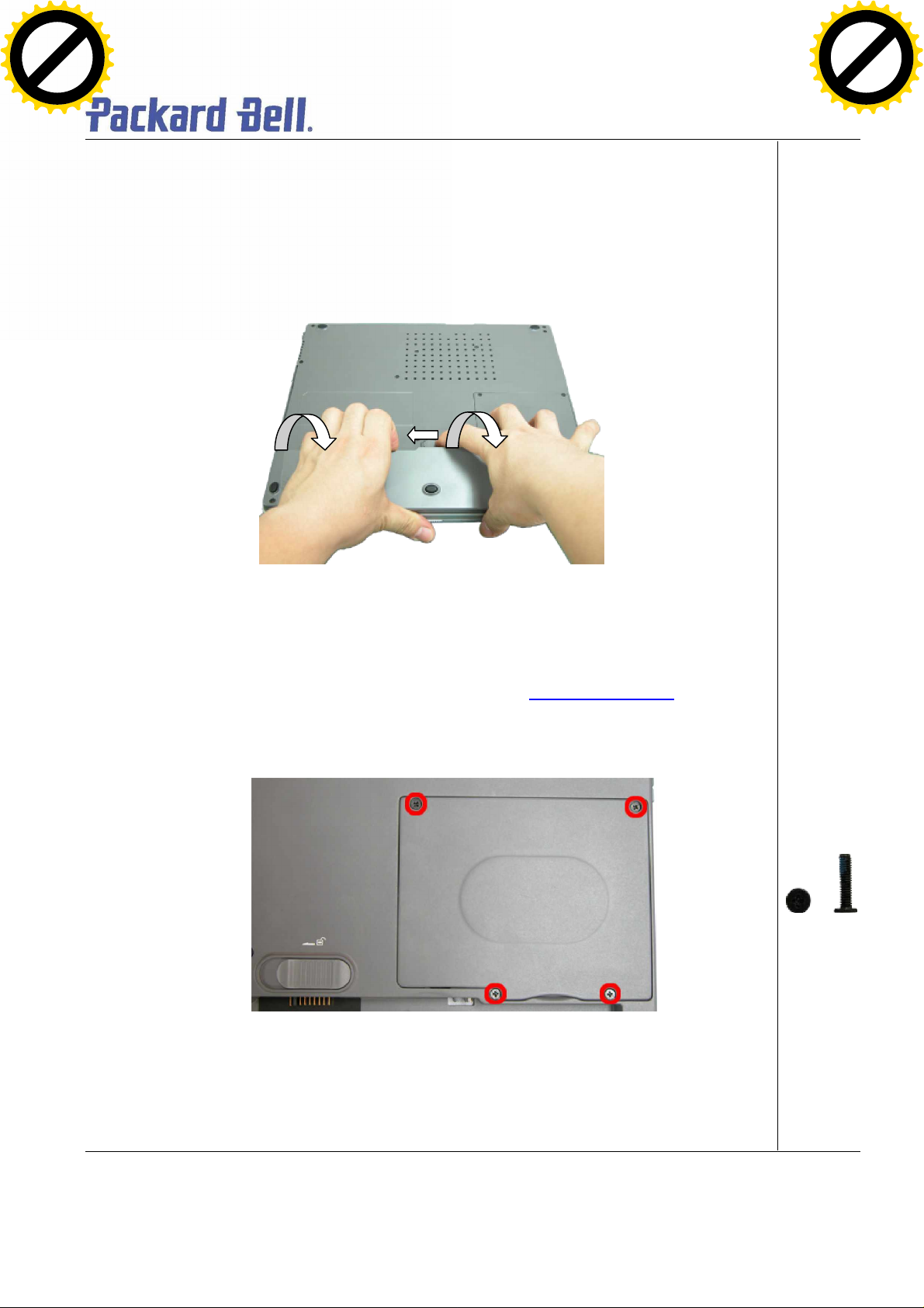
Perform the following steps to remove the battery:
1. Make sure to power off the EasyNote T5 first.
2. Turn the unit u pside down.
3. Unlock the battery and slide it ou t of its p l ace as the arrow shows in Fig. 1
Fig. 1 Removin g t he batt ery
Removing the Hard Disk Drive
To remove the hard disk drive, first rem ove the battery (see Remov ing th e Battery), then perform
the following steps:
1. R emove the screws as sho wn in F ig. 2
Fig. 2 Removing the Hard disk drive cover
M2.5x 11 Black
2. Lift up the ha rd disk d rive and disconnect it as sho wn in Fig. 3
Packard Bell EasyNot e T5 Disassemb ly Manual
Page 5
Page 6
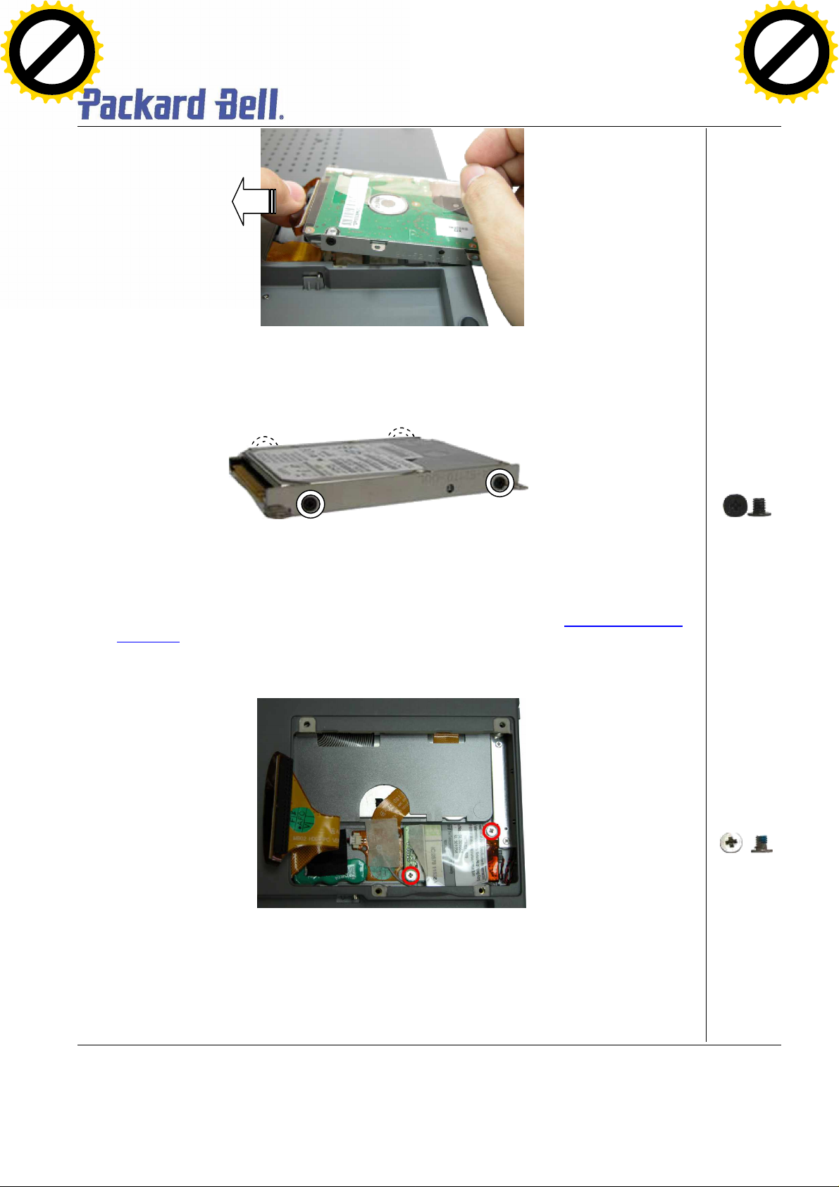
Fig. 3 Disconnecting the hard disk drive
Click to buy NOW!
P
D
F
-
X
C
H
A
N
G
E
w
w
w
.
d
o
c
u
-
t
r
a
c
k
.
c
o
m
Click to buy NOW!
P
D
F
-
X
C
H
A
N
G
E
w
w
w
.
d
o
c
u
-
t
r
a
c
k
.
c
o
m
3. Un scre w the four sc rews on both sides of the hard d isk drive as shown in Fig. 4
Fig. 4 Unscre wing the hard d isk d rive brac ke t sc rews
Removing the MDC Modem Module
To remove the MDCmodem module, first remove the hard disk drive (see Remov ing the Hard
Disk Drive), then perform the following steps:
1. R emove the screw shown in Fig. 5
M3x 4 Black
M2.5x3.5 Sliver
Fig. 5 Removing the screws on the MCD modem
2. Care fully lift up MDC modem module.
3. D isconnect the cable atta ched to the MDC m odem and put the modem aside.
Packard Bell EasyNot e T5 Disassemb ly Manual
Page 6
Page 7
Removing the Keyboard Cover
Click to buy NOW!
P
D
F
-
X
C
H
A
N
G
E
w
w
w
.
d
o
c
u
-
t
r
a
c
k
.
c
o
m
Click to buy NOW!
P
D
F
-
X
C
H
A
N
G
E
w
w
w
.
d
o
c
u
-
t
r
a
c
k
.
c
o
m
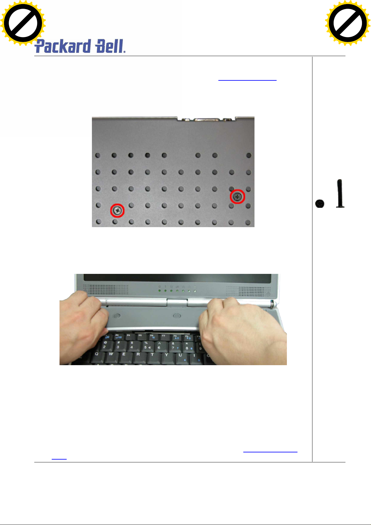
To remove the Keyboard Cover , first remo ve the battery (see Re moving the Battery
perform the following steps:
1. R emove the screw as shown in Fig. 6
Fig. 6 Removing Keyboard Cover screws
), then
M2x15 Black
2. R emove the Ke yboard Co ver as sho wn in Fig. 7
Fig. 7 Removing the Keyboard Cover
Removing the Keyboard
To remove the Keyboard module, first remove the keyboard cover (see Removing keyboard
cover), then perform the following steps:
Packard Bell EasyNot e T5 Disassemb ly Manual
Page 7
Page 8
1. R emove the screws as sho wn in F ig. 8
A
Click to buy NOW!
P
D
F
-
X
C
H
A
N
G
E
w
w
w
.
d
o
c
u
-
t
r
a
c
k
.
c
o
m
Click to buy NOW!
P
D
F
-
X
C
H
A
N
G
E
w
w
w
.
d
o
c
u
-
t
r
a
c
k
.
c
o
m
Fig. 8 Removing the screws holding the keyboard
Note: The screw “A” located on the h ard disk slot cover holds the hard disk drive and the keyboa rd.
2. Carefully lift u p the keyboard.
3. Release the keyboard FPC cable as s hown in Fig. 9 and put th e keyboard a side
M2.5x 11 Black
Fig. 9 Removing the keyboard FPC cable
Removing the Optical drive & Heat plate
To remove the optical drive & heat plate, first remove the keyboard cover (see Remov ing the
keyboard cover), remove the keyboard (see Removing the keyboard) then perform the following
steps:
1. R emove the screw as shown in Fig. 10
Packard Bell EasyNot e T5 Disassemb ly Manual
Page 8
Page 9

Fig. 10 Removing the screws on Heat Plate
A
Click to buy NOW!
P
D
F
-
X
C
H
A
N
G
E
w
w
w
.
d
o
c
u
-
t
r
a
c
k
.
c
o
m
Click to buy NOW!
P
D
F
-
X
C
H
A
N
G
E
w
w
w
.
d
o
c
u
-
t
r
a
c
k
.
c
o
m
Note: If you want to disassemble the Optical Drive, you are required to release Screw “A” only.
2. Push the Optical Drive module out from th e base unit as shown in Fig. 11
M2.3 x 6 Sliver
Fig. 11 Pushing Optical Drive module out from base unit
3. C arefully remove the heat p late from the base unit.
Packard Bell EasyNot e T5 Disassemb ly Manual
Page 9
Page 10

Fig. 12 Re mov ing Heat plate from base unit
Click to buy NOW!
P
D
F
-
X
C
H
A
N
G
E
w
w
w
.
d
o
c
u
-
t
r
a
c
k
.
c
o
m
Click to buy NOW!
P
D
F
-
X
C
H
A
N
G
E
w
w
w
.
d
o
c
u
-
t
r
a
c
k
.
c
o
m
Note: When assembling the heat plate, make sure that these three hocks on the heat plate are properly
inserted into the openings located on the top cover.
Removing the Memory Module
To remove the memory module, first remove the Ke yboa rd cover (see Removing the keyboard
cover), remove the ke yboard (see Removing the keyboard), remove heat plate (see Removing
heat plate) then perform the following step s:
1. Unclip memor y module as shown in Fig. 13
2. Remove the Memory Module f rom its slot and put it aside.
Removing the Wireless Module
To remove the Wireless Module , first remo ve the keyboard cover (see Removing the keyboard
cover), remove the ke yboard (see Removing the keyboard), remove the heat plate (see
Packard Bell EasyNot e T5 Disassemb ly Manual
Fig. 13 Remov ing the memory module
Page 10
Page 11

Removing heat plate), then perform the follo wing steps :
Click to buy NOW!
P
D
F
-
X
C
H
A
N
G
E
w
w
w
.
d
o
c
u
-
t
r
a
c
k
.
c
o
m
Click to buy NOW!
P
D
F
-
X
C
H
A
N
G
E
w
w
w
.
d
o
c
u
-
t
r
a
c
k
.
c
o
m
1. Discon nect the wireless a ntenna connectors as sho wn in Fig. 1 4
Fig. 14 Disconnecting the wireless antenna
Note: You might consider disconnecting the touch pad flat cable before removing the wireless module.
2. Unclip the wirel ess module to re lease it f rom slot a nd put it aside .
Removing Heat Sink & CPU
To remove the Heat Sink & CPU, first remove the Keyboard Cover (see Removing the keyboard
cover), remove the ke yboard (see Removing the keyboard), remove optic al drive & heat plate
(see Removing optical drive & heat plate) then perform the following steps:
1. Release the scre ws on the heat sink in de scending order (4à3à2à1) as shown in Fig. 15
Fig. 15 Releasing the heat sink screws
Note: When assembly the heat sink, tighten the heat sink screws according to the ascending order
(1à2à3à4). This is to ensure a well d istributed pressure over the CPU and to prevent damaging the CPU
M2.5x 11 Black
2. Care fully remove the heat s ink from the C PU socket as sh own in F ig. 16
Packard Bell EasyNot e T5 Disassemb ly Manual
Page 11
Page 12

Fig. 16 Removing the heat sink
CPU socket; car efully li ft up the CPU and
Click to buy NOW!
P
D
F
-
X
C
H
A
N
G
E
w
w
w
.
d
o
c
u
-
t
r
a
c
k
.
c
o
m
Click to buy NOW!
P
D
F
-
X
C
H
A
N
G
E
w
w
w
.
d
o
c
u
-
t
r
a
c
k
.
c
o
m
3. Use flat sc rews driver to relea se the CPU from the
put it in a safe place.
Removing the LCD Module
To remove LCD Module, first remove the Keyboard Cover (see Removing the keyboard cover)
then remove the keyboard (se e Removing the keyboard
1. Unsc rew the two LCD connector screws an d also, dis connec t the speaker connecto r as
Fig. 17 Releasing the CPU
):
Packard Bell EasyNot e T5 Disassemb ly Manual
Page 12
Page 13

shown in Fig. 18
Click to buy NOW!
P
D
F
-
X
C
H
A
N
G
E
w
w
w
.
d
o
c
u
-
t
r
a
c
k
.
c
o
m
Click to buy NOW!
P
D
F
-
X
C
H
A
N
G
E
w
w
w
.
d
o
c
u
-
t
r
a
c
k
.
c
o
m
Fig. 18 Disconnecting the LCD & speaker connectors
2. Rem ove the LCD cab le cover with a small flat screws dri ver as shown in Fig. 19 .
M2.5x 11 Black
Fig. 19 Removing the LCD cable Cover
3. Rel ease the screws at rear side of the unit as shown in Fig. 20
Packard Bell EasyNot e T5 Disassemb ly Manual
Page 13
Page 14

Fig. 20 LCD hinge screws at the rear
Click to buy NOW!
P
D
F
-
X
C
H
A
N
G
E
w
w
w
.
d
o
c
u
-
t
r
a
c
k
.
c
o
m
Click to buy NOW!
P
D
F
-
X
C
H
A
N
G
E
w
w
w
.
d
o
c
u
-
t
r
a
c
k
.
c
o
m
4. Unsc rew the two screws located on the bottom of the unit as sho wn in Fig. 21
Fig. 21 LCD hinge screws at the bottom
5. Careful ly lift the LCD module out of the system and pu t it a side .
M2x 6 Black
M2x 6 Black
Removing the LCD Panel
To remove the LCD Panel, first remove the LCD Module (see Re moving the LCD Module
perform the following steps:
1. Unscrew all screws shown in Fig. 22
Packard Bell EasyNot e T5 Disassemb ly Manual
), then
Page 14
Page 15

Fig. 22 Screws on the LCD Module
AAAAB
B
Click to buy NOW!
P
D
F
-
X
C
H
A
N
G
E
w
w
w
.
d
o
c
u
-
t
r
a
c
k
.
c
o
m
Click to buy NOW!
P
D
F
-
X
C
H
A
N
G
E
w
w
w
.
d
o
c
u
-
t
r
a
c
k
.
c
o
m
2. R elase the LCD Bezel carefully and put it aside as shown in Fig. 23
A = M2x3.5
Silver
B= M2x5
Silver
Fig. 23 Removing the LCD Bezel
3. Unsc rew all scre ws encircled in Fig. 24 disconnec t the inverter board and put it aside.
Packard Bell EasyNot e T5 Disassemb ly Manual
Page 15
Page 16

M2x5 Silver
Click to buy NOW!
P
D
F
-
X
C
H
A
N
G
E
w
w
w
.
d
o
c
u
-
t
r
a
c
k
.
c
o
m
Click to buy NOW!
P
D
F
-
X
C
H
A
N
G
E
w
w
w
.
d
o
c
u
-
t
r
a
c
k
.
c
o
m
Fig. 24 Removing the inverter board screws
4. Care fully lift u p LCD pa nel an d disconnect the LCD cable from the penal.
5. Rem ove the screws a t both sides of the LCD panel in order to re le ase the LCD h inges as
shown in Fig. 25 .
Fig. 25 Removing the LCD Panel hinges
Removing the Top Cover
M2x 3.5 Sil ver
Packard Bell EasyNot e T5 Disassemb ly Manual
Page 16
Page 17

To remove the Top Cover, first remo ve the Keyb oard Cover (see Remo v i ng the key board cov e r
),
Remo ving the
ABA
A
B
Click to buy NOW!
P
D
F
-
X
C
H
A
N
G
E
w
w
w
.
d
o
c
u
-
t
r
a
c
k
.
c
o
m
Click to buy NOW!
P
D
F
-
X
C
H
A
N
G
E
w
w
w
.
d
o
c
u
-
t
r
a
c
k
.
c
o
m
remove the keyboard (see Removing the keyboard), remove the LCD module (see
LCD Module) then perform the follo wing steps:
1. D isconnect the MIC c onnector on the DC/DC board.
2. Rel ease all screws sho wn in Fig. 26
Fig. 26 Removing the Top cover screws
3. Flip over the unit and remove the screws as sho wn in Fig. 27
A = M2x6
Black
B = M2.5x12.5
Silver
A = M2x15
Black
B = M2.5x11
Black
Fig. 27 Removing the Top cover screws on the bottom of the system
4. Remove all scre ws in the battery c ompartment as sho wn in Fig. 28
Packard Bell EasyNot e T5 Disassemb ly Manual
M2x3 Sliver
Page 17
Page 18

Fig. 28 Battery Compartment
Click to buy NOW!
P
D
F
-
X
C
H
A
N
G
E
w
w
w
.
d
o
c
u
-
t
r
a
c
k
.
c
o
m
Click to buy NOW!
P
D
F
-
X
C
H
A
N
G
E
w
w
w
.
d
o
c
u
-
t
r
a
c
k
.
c
o
m
5. Carefull y lift up and release the top cove r and pu t it aside .
Note: Remember to disconnect the touch pad cable before lifting up the top cover. On the VGA connector
area use extra care to release the top cover.
Removing the Touch Pad
To remove the Touch Pad, first remove the Top Cover (see Removing the Top Cover), then
perform the following steps:
Fig. 29 Removing the top cover
Packard Bell EasyNot e T5 Disassemb ly Manual
Page 18
Page 19

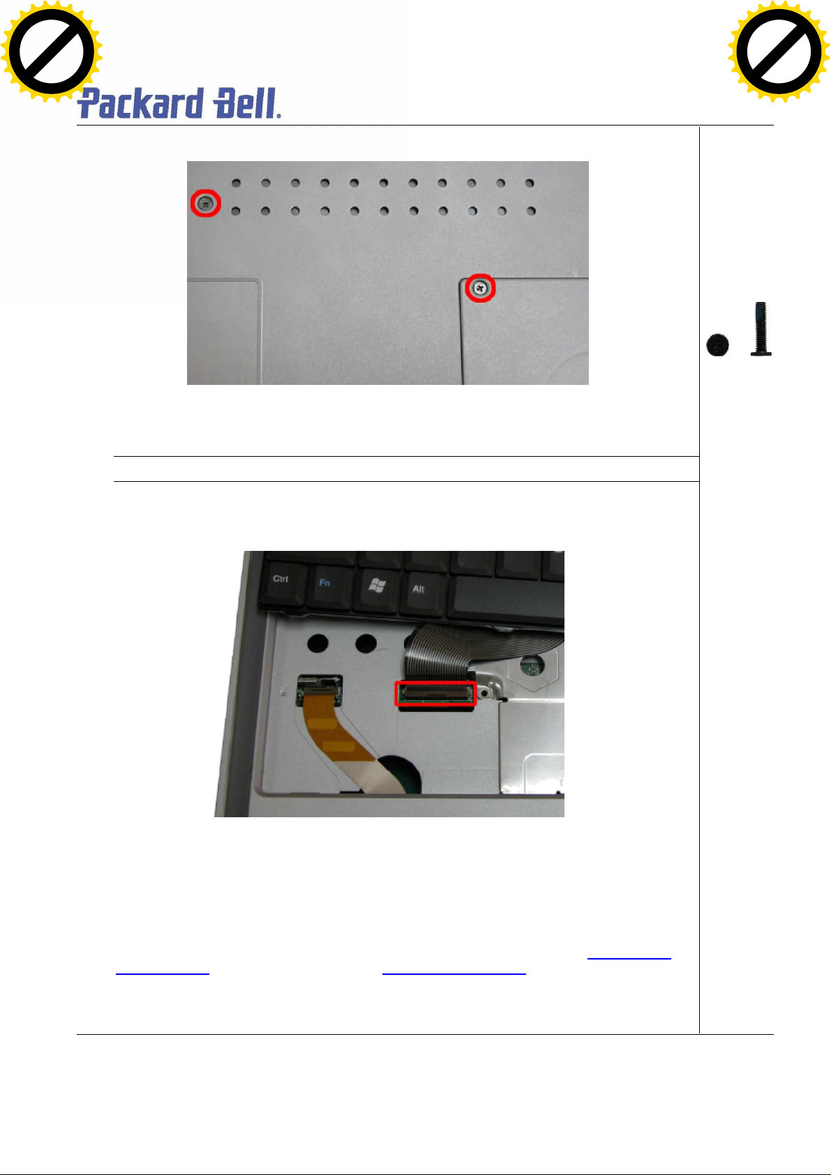
1. On the other side of the to p cover unscrew the two screws on the T ouch Pad assembly as
Click to buy NOW!
P
D
F
-
X
C
H
A
N
G
E
w
w
w
.
d
o
c
u
-
t
r
a
c
k
.
c
o
m
Click to buy NOW!
P
D
F
-
X
C
H
A
N
G
E
w
w
w
.
d
o
c
u
-
t
r
a
c
k
.
c
o
m
shown in Fig. 30 and remove the Touch Pad assy from the palm rest.
M2x 3.5 Sil ver
Fig. 30 Touch Pad Assembly
Removing the DC/DC Board
To remove the DC/DC board, first remove the Top Co ver (see Removing the Top Cover), then
perform the following steps:
1. Rem ove the sc rew on the DC/DC board as shown in Fig. 31
Packard Bell EasyNot e T5 Disassemb ly Manual
Page 19
Page 20

Fig. 31 DC/DC Boa rd
Click to buy NOW!
P
D
F
-
X
C
H
A
N
G
E
w
w
w
.
d
o
c
u
-
t
r
a
c
k
.
c
o
m
Click to buy NOW!
P
D
F
-
X
C
H
A
N
G
E
w
w
w
.
d
o
c
u
-
t
r
a
c
k
.
c
o
m
2. Carefull y remove the DC/DC board as shown in Fig. 32 and put it aside.
M2.5x 11 Black
Removing the Main Board
To remove the Main board, first open the Top Cover (see Remov ing the Top Cover
DC/DC board (see Removing DC/DC board
1. Remove the screws holding the m ain board in place as shown in F ig. 33
Fig. 32 Removing the DC /DC Board
) then perform the following steps:
Packard Bell EasyNot e T5 Disassemb ly Manual
), remove
Page 20
Page 21

A = M2x5
B
A
A
Click to buy NOW!
P
D
F
-
X
C
H
A
N
G
E
w
w
w
.
d
o
c
u
-
t
r
a
c
k
.
c
o
m
Click to buy NOW!
P
D
F
-
X
C
H
A
N
G
E
w
w
w
.
d
o
c
u
-
t
r
a
c
k
.
c
o
m
Silver
B = M2.5x8
Silver
Fig. 33 Removing the main board scre ws
2. Disconnect the VGA connector from the base a s shown in Fig. 34
Fig. 34 Disconnecting the VGA connector
3. Lift the main board out of the system and pu t it as ide (Fig. 35 ).
M2.5x1 0 silver
Packard Bell EasyNot e T5 Disassemb ly Manual
Page 21
Page 22

DIP Switch Settings
Dip Switch
Description
Seeting
Keyboard
Keyboard
ON : Enable
Password override.
ON: Override
OFF OFF US Keyboard
Click to buy NOW!
P
D
F
-
X
C
H
A
N
G
E
w
w
w
.
d
o
c
u
-
t
r
a
c
k
.
c
o
m
Click to buy NOW!
P
D
F
-
X
C
H
A
N
G
E
w
w
w
.
d
o
c
u
-
t
r
a
c
k
.
c
o
m
Fig. 35 Re moving Main Board
Bit1
Bit2
Bit3
Select1
Refer to the below table
Refer to the below table
Select2
Reserved Reserved
BIOS CrisisBit4
OFF: Normal (Default)
DVDSELBit5
ON : connect to GND
OFF : NC
PasswordBit6
OFF: Available (factory setting)
Bit 1 Bit 2 Keyboard code
ON OFF JP Keyboard
OFF ON Reserved
ON ON UK Keyboard
Packard Bell EasyNot e T5 Disassemb ly Manual
Page 22
Page 23

Screws
Click to buy NOW!
P
D
F
-
X
C
H
A
N
G
E
w
w
w
.
d
o
c
u
-
t
r
a
c
k
.
c
o
m
Click to buy NOW!
P
D
F
-
X
C
H
A
N
G
E
w
w
w
.
d
o
c
u
-
t
r
a
c
k
.
c
o
m
M2.5x5.6 Silver M2.5x3.5 Sil ver M2.5x8 Sli ver M2.5x10 Silver
M2 .5x11 Bla ck M2.5x12.5 Silver M2.5x 15 Black M2x3 Sliver
M2x6 Black M3x4 Black M2.5x5 Sli ver
Packard Bell EasyNot e T5 Disassemb ly Manual
Page 23
Page 24

Disclaimer
Click to buy NOW!
P
D
F
-
X
C
H
A
N
G
E
w
w
w
.
d
o
c
u
-
t
r
a
c
k
.
c
o
m
Click to buy NOW!
P
D
F
-
X
C
H
A
N
G
E
w
w
w
.
d
o
c
u
-
t
r
a
c
k
.
c
o
m
The informa tion in this guide is sub jec t to change witho ut no tice.
This guide conta ins informa tion prote c ted by cop yright. No part of this guide may be photocopied or reproduced in
any form or by any means withou t pr ior writte n consent from NEC Computers International BV.
NEC COMPUTERS INTERNATIONAL BV SHALL NOT BE LIABLE FOR TECHNICAL OR EDITORIAL ERRORS
OR OMISSIONS CONTAINED HEREIN; NOR FOR INCIDENT AL OR CONSEQUENTIAL DAMAGES RESULTING
FROM THE FURNISHING, PERFORMANCE, OR USE OF THIS MATERIAL.
Copyright © 2003 NEC Computers International BV. All rights reserved.
NEC is a tradem ark of NEC Computers International BV.
The names of actual companies and products mentioned herein may be trademarks and/or register ed trademarks
of their respective owners.
Source & Credits:
Versa P600 Disassembly Manual
Author: Allen Koay
First Edition: Septem ber 2003
Document Part Number:
Version: 1.0
NECC M
A division of NEC Computers International BV
Revision Details:
Author: Dean Egberts
Date: September 2003
Document Part Number: 6906480100
Version: 2.0
For Packard Bell
A division of NEC Computers International B.V.
Packard Bell EasyNot e T5 Disassemb ly Manual
Page 24
 Loading...