

Page 1
XR 4000 Real-Time
X-Ray Inspection System
Operation Manual
Rev A-3-2001-PRM
P/N 5050-0516
PACE USA PACE Europe
9030 Junction Drive Sherbourne House,
Annapolis Junction, MD 20701 Sherbourne Drive
USA Tilbrook, Milton Keynes
MK7 8HX
United Kingdom
Tel: (301) 490-9860 Tel: (44) 1908 277666
Fax: (301) 490-0193 Fax: (44) 1908 277777
Page 2

1. XR 4000 Safety Information
IMPORTANT: READ THIS FIRST
It is essential that the operator of the XR 4000 read and understand the following
safety war nings PRIOR to operation.
The XR 4000 is designed to provide safe and efficient operation. However, any
equipment producing ionizing radiation (x-rays) must be considered hazardous
and should be treated accordingly. When operating this equipment, observe the
following:
• PACE strongly recommends that all maintenance be performed by a qualified
service technician.
• The XR 4000 x-ray tube produces high voltages of up to 70,000 volts. Under no
circumstances should the case be disassembled or modified as severe electrical
shock may occur.
• The XR 4000 is designed to ensure adequate radiation shielding. Even so,
always be aware that the ionizing radiation (x -rays) can constitute a distinct
hazard if not employed in strict accordance with instructions provided in this
manual for maximum operator safety.
• Exposure to excessive quantities of radiation can be dangerous to your health.
Avoid not only direct radiation exposure, but also to secondary or scattered
radiation which occurs when an x-ray beam strikes or has passed through any
material.
• Do not insert any part of the body into the inspection chamber while x -rays are on.
Although the XR 4000 operates at an extremely low x -ray dose, unnecessary
radiation exposure should be avoided. If an item becomes jammed or lodged in
the inspection area, the XR 4000 should be turned off before any attempt is made
to clear the inspection chamber.
• PACE strongly recommends that all personnel operating the XR 4000 wear a
radiation film dosimeter badge. See Section 15. This badge records an exposure
history for the operator and acts as a constant reminder to the operator to use
caution and safe work practices when operating the XR 4000.
• The radiation exposure dosage received by personnel working with x-ray
inspection equipment should not exceed those limits set by local regulations
relating to ionizing radiation.
Page 2 of 26
Page 3

• Adequate warning signs and symbols should be displayed in the vicinity of the XR
4000 warning of possible x-ray exposure. Any warning lamps and signals should
be checked prior to operating the XR 4000.
• The electrical circuits of the XR 4000, although enclosed for operator protection,
must be considered as a potential hazard. Strict observance of safety practices
pertaining to operation and maintenance is essential. Proper electrical grounding
must always be used.
• Before operating the XR 4000, all personnel designated or authorized to operate
the unit, as well as those supervising its operation, should have a full
understanding of how it works. Additionally , they should be familiar with
established radiation safety exposure practices sanctioned by the National
Bureau of Standards Handbook, “X-ray Protection” HB93, pertaining to x-ray
protection.
• Service personnel should read this manual and be familiar with its contents before
attempting to adjust or repair this equipment.
2. Radiation Safety Information
Federal, State and Local Radiation Regulations (US ONLY)
This cabinet x-ray system was designed to conform to U.S. and Food and
Drug Administration (FDA) requirements as stated in the Code of Federal
Regulations, Title 21 (21CFR). These requirements (often referred to as the
CDRH or BRH regulations) govern the design and manufacture of all
equipment that produces ionizing radiation. Such equipment inclu des
television sets and microwave ovens, as well as cabinet x -ray systems. In
fact, the maximum allowable radiation emission for cabinet x-ray systems is
the same as that set for television sets and microwave ovens. Therefore,
respect to radiation emission, a properly maintained and operated cabinet xray system is a safe as a television or microwave oven.
Page 3 of 26
Page 4

Warning: Failure to adhere to the following warnings may result in
exposure to radiation:
• Do not operate the x-ray system unless all system components and
features are in good repair.
• Never attempt to remove any system component or bypass any system
function.
Several features are included in the system design to provide for radiation
safety. The controls (including key switches), control circuitry, leaded
components (including the leaded acrylic windows), physical barriers,
interlocks, and status and warning indicators each contribute to overall
radiation safety.
The Federal Aviation Administration (FAA), Occupational Safety and Health
Administration (OSHA), most state and some local government agencies
typically have specific standards regarding operational safety and constraints
regarding the modification of x-ray systems conforming to 21CFR (mentioned
above).
Typically, an x-ray system must be registered with the appropriate state
agency, by the physical possessor of the system, regardless of the legal
owner. Frequently, registration must occur prior to the x-ray system being
placed into service. Regulations may require initial and periodic inspections by
a government agency or a qualified vendor. In addition, the regulations may
require the implementation of standardized operating procedures, specialized
training, the distribution and use of exposure monitoring badges and posting of
radiation exposure warnings and other special notices. Radiation safety
requirements may differ slightly from one jurisdiction to another. It is the
users responsibility to ensure that the x-ray system is installed and
operated in compliance with all applicable governmental regulations.
Failure to comply may result in substantial penalties.
Page 4 of 26
Page 5

3. Radiation Safety Guidelines
To ensure the health and safety of the operator and all others in the vicinity of
operating x-ray inspection equipment, the following guidelines are recommended
for establishing a basic radiation safety program.
Note: Federal, State, and some local government agencies
may have more stringent regulations concerning the operation
and use of equipment that produces ionizing radiation (x-rays).
The requirements of these governing agencies supersede the
recommendations made by the manufacturer.
1. A copy of the operating instructions should be kept at the machine at
all times.
2. Personnel operating the equipment should be trained in the proper and
safe operation of the machine.
3. Radiation surveys should be performed periodically to ensure that the
amount of radiation being emitted by the machine is less than
0.5mR/hour. We recommend performing a radiation survey:
• Following initial installation – before placing the x-ray system
into service.
• Whenever the x-ray system is relocated.
• Whenever the x-ray system receives a strong jolt (e.g., being
dropped more than one inch or struck sufficiently hard to dent or
deform the exterior cabinet).
• Whenever a leaded component (such as the x-ray generator,
shielding, inspection tunnel curtains, LXDA or collimator cover)
is removed for any reason or period of time.
• Annually – from the date of the most recent radiation survey
4. All controls and indicators should be checked daily to ensure proper
operation.
5. Do not operate the x-ray system if it is not in good repair. Do not
attempt to remove or bypass any controls (e.g. foot pedals and key switches), interlocks, status indicators, leaded components (including
the inspection tunnel curtains) or physical barriers. In the event of
failure or breakage, these items should only be replaced by a qualified
service technician using factory-approved parts.
6. Service of the equipment should only be performed by or under the
instruction of trained PACE personnel.
Page 5 of 26
Page 6

Many users choose to issue periodic radiation film badges to assure employees
that they are not being exposed to significant levels of radiation and to provide
added assurance that radiation emissions are well within regulatory limits.
4. Radiation Safety Training
PACE can provide (or make referrals to those who can) operation and radiation
safety training to ensure that the facility is in compliance with all state and federal
radiation regulations.
Page 6 of 26
Page 7
5. Operation
Bare Board
Hole/Pad Offset
BGA Voiding
Leaded Component
Non-Co planarity
Leaded Component
Opens
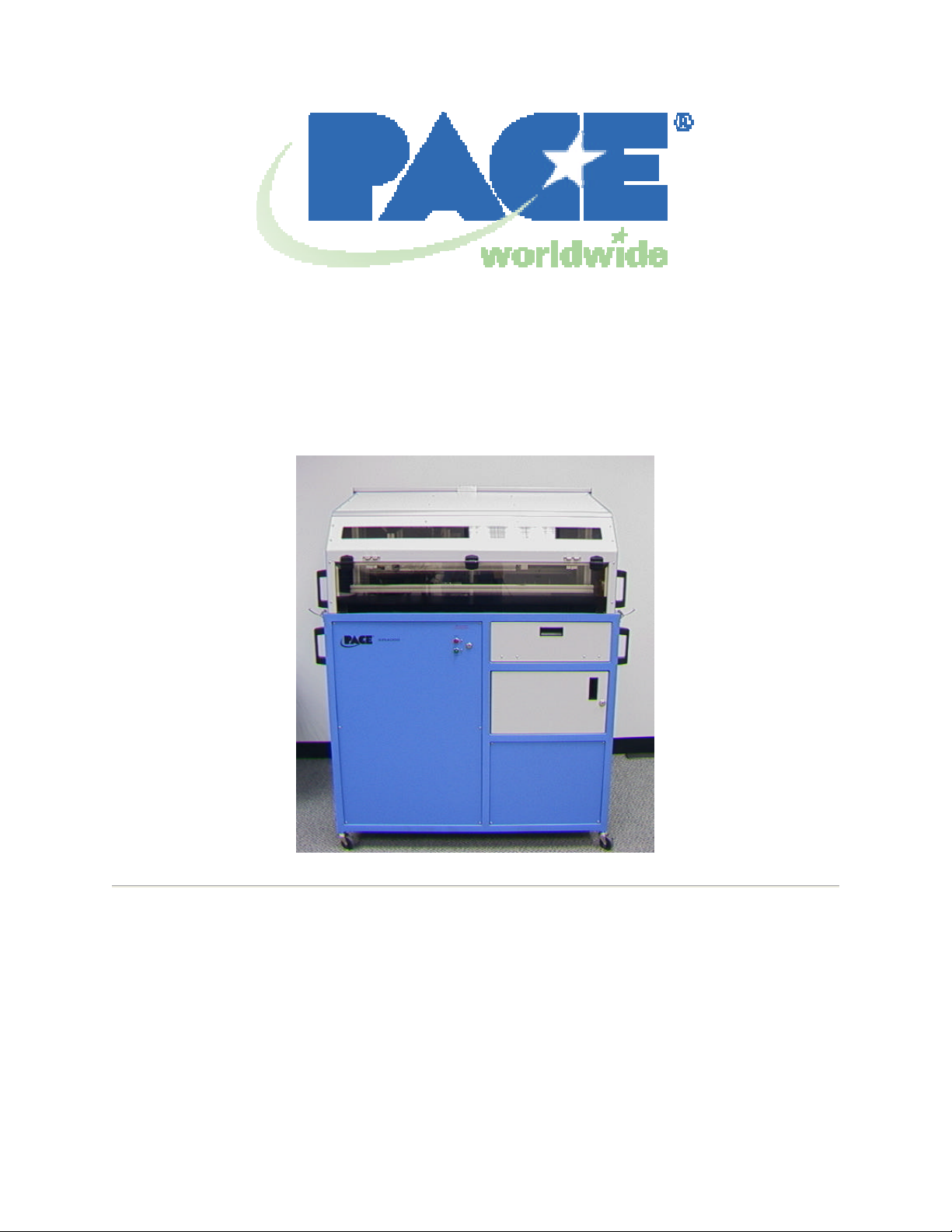
XR 4000
The XR 4000 Real Time Inspection System is a powerful
tool in the quality control and process verification of all
aspects of microelectronics manufacturing. The XR 4000
provides rapid, real-time x-ray inspection for production
and rework environments. Its self-contained console
design supports easy customizing for numerous
applications, including multi-layer PCBs, small hole
drilling, large back-planes and assemblies with advanced
components, such as BGAs and chip-scale packages.
In bare board applications, it can be used to check for
interlayer shift and drilled hole-to-pad offset. Inspection is
performed following lamination, to determine the
presence and degree of interlayer shifts. At the onset of
either conventional or small hole drilling, inspection is
used to qualify hole -to-pad alignment. In addition to
enhancing product quality, x -ray inspection enables users
to control costs by eliminating defective boards early in
the production process. It can also be used to quality
control incoming boards from vendors or customers so
that defects can be detected before problems occur.
For surface mount components, it is used to verify
lead/pad co-planarity, shorts, opens, and solder bond
quality. It can be used to check resistors and capacitors
as well as IC’s for internal damage and verify adjustments
throughout the placement and reflow processes.
For BGA’s, the XR 4000 can be used to check for all
potential defects including: shorts, opens, misregistration, non-wetting, solder ball voids, and
delamination. X-ray is used to verify proper reflow
profiles for advanced packages, and to control rework
process.
Page 7 of 26
Page 8
6. Set Up
115 V Unit
230 V Unit
A. XR 4000 as a stand-alone inspection station
Place the XR 4000 in a location where it will not be in the way and will not be
damaged. Images can be displayed on either a monitor, the XR 4000 PC, or
one of PACE’s BGA rework systems, depending on the option purchased.
Familiarize yourself with the back of the XR 4000. Note that the 115 V
system has a multi strip mounted on the back to plug in the PC, video
monitor, or other accessories.
Foot Pedal
Connection Composite Video Out
Locate the foot pedal, composite video cable, and power cord. These should
be connected as shown in Figure 1. The power cord should be connected to a
properly grounded 120 VAC power supply.
A-1. If the PC package was
AC Power Receptacle
Figure 1. The back of the XR 4000
purchased, first, install the PC
mounting brackets on the side of
the XR 4000 as shown. Next,
mount the PC on the side of the
XR 4000 as shown in the figures
to the right.
On the back of the computer, locate the video acquisition card and
connect the included video input cable. One of
the B/C connectors should then be connected to
the video out on the back of the XR 4000. The
BGA cable should be installed from the VGA
connector on the video acquisition card to th e
VGA Video Cable Connection
Page 8 of 26
Page 9

LCD monitor.
A-2. If the non-PC model was purchased, the video out on the back of the
unit needs to be connected to video input on the side of the LCD monitor.
using the adapter provided.
The monitor used to view the images can be placed on the work surface next to
the XR 4000 or can be mounted on top of the XR 4000 using the monitor
bracket provided. ALWAYS REMOVE THE LCD MONITOR BEFORE
OPENING THE XR 4000, otherwise the monitor may be damaged.
B. XR 4000 used with the TF 3000 BGA/CSP Rework Center
Place the XR 4000 near the TF 3000 to allow for the connection of the
composite video cable to the PC. Locate the foot pedal, composite video
cable, and power cord. These should be connected as shown in Figure 1.
The other end of the composit e video cable should
be connected to one of the available composite
video inputs on the connector that is installed on the
video input port on the video acquisition card.
VGA Video Cable Connection
Page 9 of 26
Page 10

7. XR 4000 Initial Power-up and Operational Test
A. The XR 4000 can be used as a closed cabinet
system with PCB manipulator or very long PCBs
can be slid through the openings that are
protected with leaded vinyl. In either case, the lid
on the XR 4000 MUST BE CLOSED AND
LOCKED before trying to operate the unit. An
interlock is installed on the machine that will
prevent its use unless the lid is closed and the
interlock is engaged. Additionally, the access
panel on the front of the system that can be
raised to get access to the cabinet when placing
a PCB into the PCB manipulator MUST BE
CLOSED before the unit will operate. An
interlock is installed on the access panel that will
prevent its use unless the access panel is closed
and the interlock is engaged.
B. The control panel on the XR 4000 is a retractable
Latch in closed position
panel on the right hand side of the system. Make
sure the control panel is open before attempting
to use the system. For a detailed explanation of the XR 4000 control panel, see
Section 8.
C. The system should be fully set up according to the System Setup Section before
starting these procedures.
1. To turn on the power, turn the key to the
ON position. The key is required to turn on
the power and cannot be removed unless
the key has been returned to the off
position. The green system light should
also turn on when the key is engaged.
2. Make sure that there is nothing inside the
inspection chamber and depress and hold
the foot pedal. The image on the PC or
video monitor should change to a bright,
slightly grainy image. This is the blank xray image.
3. Release the foot pedal and the image will
disappear.
Page 10 of 26
Page 11

4. Depress the foot pedal again and now look at the front panel. The red “x ray on” light should illuminate and remain on for as long as you hold down
the foot switch. Release the foot pedal.
5. Place a component (such as
a circuit board) inside the
inspection chamber directly
underneath the x-ray tube.
A Red LED indicator will
assist in locating the
component under the X-Ray
head.
6. Depress and hold the foot
switch. The x-ray image of
the component should now
be visible.
7. Using the PCB manipulator, move the PCB so the component you are
inspecting is directly under the X-Ray head, while the foot switch is
depressed. The image should move with the component. The image will
display a trail behind the component, which will disappear when the
component has stopped moving. This is a normal occurrence and is a
function of the image processor. The video processor included with this
system is preset to 8 frame averaging. Averaging makes the x-ray image
less grainy and can be adjusted to improve image quality but with an
increase in motion lag. Refer to the section on the image processor for
further information.
8. Images may be captured electronically when the XR 4000 is used with the
XR 4000 PC or TF1500 PC or TF 3000 PC.
Your system is now ready for use. Please refer to the individual component
sections found later in this manual for further adjustment.
Page 11 of 26
Page 12

8. XR 4000 Adjustment Features
A. Introduction
The XR 4000 is fitted with an XRTV Zoom X-Ray camera. The zoom camera
magnification can be varied from 7x to 40x. The memory button can be used
to store a magnification setting and to quickly return to that setting.
The XRTV Zoom X-Ray camera utilizes the latest servo-control and
microprocessor technologies to produce sharp, high resolution images at any
magnification. The camera automatically monitors and adjusts the focus and
exposure parameters.
B. Control Panel
Figure 3: XR 4000 Control Panel
1. The camera is controlled through the button and two switches mou nted on
the XR 4000 control panel. See Figure 3.
When the power is turned on, the camera automatically sets itself to 14X
magnification. This is the magnification setting that is stored in memory
when the unit leaves the factory.
The camera operates in either the ZOOM control mode or the GAIN
control mode; set by the rocker switch on the control box panel. See
Figure 3. To adjust the image magnification, place the control switch in
the ZOOM setting. The camera magnification is controlled by the +/rocker switch. Press the rocker in the + direction to increase the
magnification. Press the rocker in the - direction to decrease the
magnification.
Page 12 of 26
Page 13

As shipped from the factory, the startup setting stored in memory is 14x
magnification and auto focus m ode.
2. The memory button can be used to store and quickly return to a preset
magnification and focus setting. This function is useful if a video
measurement system is used. To store the current magnification and gain
setting, press and hold the MEMORY button for three seconds. The
camera will beep to indicate that the current setting has been stored in
memory. To restore the magnification and gain setting from memory,
press and release the MEMORY button. The camera magnification will
quickly return to the setting stored in memory.
3. Manual gain control is enabled by placing the mode switch in the “GAIN”
position. Press the rocker in the + direction to increase the gain. Press
the rocker in the - direction to decrease the gain. Press the rocker once
for each step on gain. After setting the gain, the rocker can be switched to
the ZOOM mode without losing the manual gain setting. Automatic Gain
Control is enabled if the mode switch is set to GAIN and then back to
ZOOM without using the +/- rocker switch.
4. The PCB manipulator is controlled by the joystick on the control panel. It
can be moved in the X and Y directions. The movement speed can be set
to either slow or fast by the speed switch next to the joy stick.
5. The X-Ray head on the XR 4000 is usually used in a position that is 90
degrees (perpendicular) to the PCB. It can be rotated to an angle of 45
degrees to check for “open” joints. Please Section 9. To move the X-Ray
head, use the switch on the control panel labeled “Tube Rotation”
X-Ray Head at 90 Degrees X-Ray Head at 45 Degrees
Page 13 of 26
Page 14

9. Examples of Common Defects
Bridging between solder joints is easily
identified.
Missing solder ball is easily identified.
Cold solder is signified by a jagged,
irregular edge around the perimeter of the
solder ball. Note that in this image only
some of the solder balls show this
signature.
Solder balls in the center of the package
are oversized due to the delamination and
compression under the die area.
Voids in Solder Ball
Page 14 of 26
Page 15

Solder ball is smaller than adjacent balls
and pad shadow can be seen below
indicating no contact between ball and pad.
Note figure 8 shape indicating 2 unattached
spherical shapes unlike oval shapes
adjacent to it indicating contact between
pad and solder ball.
X-Ray and Thru Hole
Straight down view, no angle. Joints
appear solid due to lead filling thru-hole.
Desoldered joint also appears to be OK.
50% angle, desoldered joint is clearly
visible. Solder in oth er joints looks fairly
consistent.
Desoldered joint is clearly visible
Beginning of figure 8 shape indicating good
fillet on both sodes of the PCB.
100% angle, desoldered joint is clearly
visible. Solder in other joints looks fairly
consistent.
Some are a little light on top, but OK as
solder is present all the way through the
thru-hole.
Figure 8 shape indicating good fillet on both
sides of the PCB is very clear on most
joints.
Page 15 of 26
Page 16

10. Troubleshooting
A. Self-Diagnostics
The XRTV zoom camera is equipped with self -diagnostic features that help to
debug certain problems that may hinder system performance. This selfdiagnostic feature will help to identify if the x-ray source is emitting x -rays,
and if the camera control microprocessor and the camera itself are
functioning normally.
To use the self-diagnostic feature, power off the entire x-ray system at the
main power switch. Turn the system back on with the main power switch. Go
to the camera controls. The camera controls should be making an audible
beep and, if equipped with a lighted Zoom/Gain switch, the LED should also
be flashing. As soon as the beeping starts (about 4 seconds after start-up)
hold down the memory button until the beeping stops. You will notice that the
image processor will not boot up and that there will be no image on the
monitor. Depress and hold the footswitch. After about 3 seconds, the
camera control box should let out a continuous beep and the AGC LED (if so
equipped) should turn on. Now release the foot switch and the LED should
turn off and the beeping should stop. The beeping and lighting of the AGC
LED signifies that the x-ray source is emitting x-rays and that the x-ray
converter inside of the camera is functioning properly. Now, press and
release the memory button. The camera control box should begin its start-up
beeping. This is testing the camera and microprocessor communications.
After about 5-7 seconds, the beeping should stop and a video signal will now
be present. Note that the image processor should now boot up properly and
an x-ray image should now appear on the monitor. If there is ever a problem
with your x-ray system, you may be asked to perform this test if you call
PACE for technical support.
B. Blurry Image
The XRTV Zoom camera employs an advanced focus system, which keeps
the image in constant focus. On occasion, the focus system will drift. This
problem occurs most often if the magnification is changed while the x -ray
source is not on. In most cases, the camera control system will refocus the
camera within 1-2 seconds. If the image appears out of focus for longer than
a few seconds, change the magnification setting while the x-ray source is on.
This should give the camera enough information to let it lock onto the proper
focus. In general, it is best to change the magnification only when the x -ray
source is on. Changing the magnification when the x-ray source is off will not
cause any damage; it will just take a few extra seconds for the camera to lock
into focus.
Page 16 of 26
Page 17

C. General Problems
If the camera does not appear to operate properly, switch off the power, wait
a few minutes and switch the power back on. If the camera is still not
operating properly, call PACE.
Page 17 of 26
Page 18

11. Specifications
• Operating voltage: 120V, 50/60 Hz or 230V, 50Hz
• Energy sensitivity: less than 15kV to greater than 160 kV
• X-Ray Tube – 70 kVA
• Resolution: greater than 20 line pairs per millimeter; can easily resolve a 1
mil bond wire
• Magnification: 7 - 40x
• Maximum field of view: 1 inch diamet er circle
• Maximum PCB size: 27” x 27” (685mm x 685mm) with PCB manipulator
27 x Unlimited (685mm x Unlimited) without
manipulator
Page 18 of 26
Page 19

12. RTVA Image Processor
The RTVA (Real-Time Video Averager) is an image processor used in the XR
4000 X-ray system. It uses video frame averaging to smooth the inherently
grainy image coming from the X-ray camera. It is located inside of the XR 4000
housing.
The RTVA is adjustable by using the front mounted switch marked “FRAME
AVERAGING”. See Figure 3. This adjusts the amount of frames that the RTVA
averages before sending the video out to the monitor. When using the switch,
please note the following frame averaging settings:
(Note that image trailing will occur at higher settings.)
Setting Effect
0 BYPASS. There is no averaging in this setting
1 2-frame averaging
2 4-frame averaging
3 8-frame averaging
4 16-frame averaging
The RTVA image processor also has a “CAPTURE” ability that is designed to
hold the current image. To use this option, just switch the front-mounted
CAPTURE/LIVE switch to the “Capture” position. See Figure 3. To return to
normal operating mode, return the switch to the “LIVE” position.
Please note that there are no user serviceable components inside. If the
component is suspected of being faulty, please call PACE.
Page 19 of 26
Page 20

13. XR 4000 Maintenance
The XR 4000 system has been designed for simple maintenance. The only
suggested maintenance is to keep the unit visibly clean and to keep the system’s
calibration up to date. Any mild surface cl eaner, like Windex, may be used to
clean the system. If you find that your system is coming close to its calibration
date, please contact PACE to schedule a calibration.
It is very important that you contact PACE early so that we may schedule servi ce
at a convenient time.
Warning: The acrylic and vinyl around the opening of
the XR 4000 contain lead. Always wash your hands
immediately after use. Eating and drinking without
washing your hands may cause you to ingest lead.
Page 20 of 26
Page 21

14. Troubleshooting
Quick Tips
The first thing to do is to
start the
system. This can solve most
In the event that your system exhibits problems, this section will familiarize you
with the basic steps to troubleshoot the
problem as well as what information PACE
will require in order to give you the best
possible service.
1. The first step in troubleshooting is that
the system must be completely shut
down and re-started. You can do this
by turning the keyed power switch, located on the front of the system, to
the “Off” position.
2. Turn the power back on.
3. There are three categories that are used to troubleshoot the system:
Power: The power category covers all problems that include lack of
power to a component or to the full system. Power problems
would include:
- The system not powering up.
- The x-ray controller’s red light does not turn on.
- The system’s green light does not function.
• Do all components power up when the main power switch
is turned on?
• Do all power-indicating lamps turn on?
• Do all power outputs show the proper voltage?
• Is the foot pedal connected?
simply try and reproblems right away.
Video: The video category covers the problems that affect the presence
of a video signal from the x-ray camera. Video problems would
include:
- No x-ray image on the monitor, but x-rays are present.
- The image processor on the system does not boot up.
- The x-ray image is fuzzy or out of focus.
• Is the video cable attached properly?
• Does an X-ray image appear on the monitor when the foot
switch is depressed?
• Does the systems image processor boot up?
• Does the X-ray monitor have a light gray screen or flicker?
Page 21 of 26
Page 22

X-Ray: The x-ray category covers the problems that affect the tube’s
emission of x-rays. The x-ray category includes:
- The red “X-Ray On” light is not turning on.
- There is no image on the monitor, but video signal is present.
- There are no x-rays being emitted from the x-ray source.
• Does an X-ray image appear on the monitor when the foot
pedal is depressed?
• Does the red “X-ray on” light turn on when the footswitch is
depressed?
Page 22 of 26
Page 23

15. Replacement Parts
Description Part Number Image
Leaded Vinyl 4’ x 2’ sheet 1335-0248-P1
Replacement X-Ray Tube 4018-0110-P1
Replacement X-Ray Zoom
4018-0111-P1
Camera
RTV Image Averager 6020-0161-P1
Control Box Assembly 4018-0113-P1
Page 23 of 26
Page 24

16. Model XR-4000 Design Safety Standards and Safe Operating Practices
Because of the low operating anode power of the XR 4000, real time x -ray
inspection system, it has been registered with the Center for Devices and
Radiological Health Branch of the FDA as an “Analytical X-ray System”. As
registered, the system has a number of safety features provided to minimize
any x-ray scatter reaching the operator.
A. Safety:
The X-Ray tube assembly is lead shielded with at least a ¾ inch space
between collimator and image plane to minimize any x -ray scatter. The
collimator insures that the x-ray beam size at the image plane is no more than
a one-inch diameter circle. The table assembly employs a lead acrylic view
panel and additional lead shielding. The highly sensitive x-ray camera
permits the x-ray tube to operate at low power (anode voltage of 70 kV and
anode current of 25 microamps) resulting in minimal x-ray scatter. All these
safety features result in a structure with radiation scatter at 5 cm from any
exposed surface less than 0.5 milliRoentgens per hour. (Radiation exposure
in an airplane at 30,000 feet during the day is greater than 0.4 milliRoentgens
per hour.)
B. Radiation safety precautions for the use of XR 4000 Real Time X-ray
Inspection System:
It is imperative that the XR 4000 be operated only by trained personnel who
are familiar with the basic safety precautions to be taken when working with xray producing equipment.
1. The key to actuate the x-rays should not be left in the equipment when
the equipment is not being used and is unattended.
2. Operators should not place hands under the leaded acrylic panel in the
front.
3. The equipment should not be operated with any panels removed.
4. Operators should be familiar with the use of the Monitor-4 radiation
survey meter.
5. Service of the equipment must be performed by or under the
instruction of trained PACE personnel.
Page 24 of 26
Page 25

C. Radiation monitoring:
Specific regulations regarding the monitoring of possible radiation leakage of
industrial x-ray cabinets are determined by the individual state or country.
There are a number of measures, which can be taken to provide a means of
cursory monitoring.
D. Dosimeter badges:
Dosimeter badges can be obtained from:
1) Siemens Dosimetry
Barrington Road
Hoffman Estates, IL 60195
(800) 666-4552 2501
2) R.S. Landauer & Co
2 Science Road
Glenwood, IL 60425
(708) 755-7000
Dosimeter badges can be placed by the equipment or worn by the
individual to constantly record any x-ray exposure. At the end of the
month a replacement dosimeter is sent and the present months dosimeter
is returned to the dosimeter service company. A report is issued monthly
tabulating any x-ray exposure received. A dosimeter service is most
useful in that documented records are established for the corporation
showing that no radiation leakage has occurred.
E. Radiation survey meters:
Radiation survey meters detect the presence of ionizing radiation and
display a value in units of mR/hr (milli Roentgens per hour). It is generally
a good idea to have, as part of a radiation safety program, a radiation
survey meter. The monitor –4EC survey meter is available from PACE.
The Monitor-4EX employs an energy compensated G-M tube to measure
the presence of radiation. It is calibrated to Cs-137. The Monitor-4EX can
be used to detect any radiation leakage from x-ray systems.
F. Radiation safety training:
PACE can provide or recommend providers of operation and radiation
safety training to ensure that the facility is in compliance with all state and
federal radiation regulations.
Page 25 of 26
Page 26

17. Warranty
PACE USA PACE Europe
9030 Junction Drive Sherbourne House,
Annapolis Junction, MD 20701 Sherbourne Drive
USA Tilbrook, Milton Keynes
MK7 8HX
United Kingdom
Tel: (301) 490-9860 Tel: (44) 1908 277666
Fax: (301) 490-0193 Fax: (44) 1908 277777
Equipment Warranties
All warranties are against manufacturing defects only. Warranties exclude
consequential damage or damage resulting from normal wear, accident, mishandling or
modification. (Customer will be advised of charges for such repairs). Liability is limited
to repair or replacement of any parts, which prove to be defective. Parts proving
defective will be replaced free of charge FOB Laurel, Maryland, USA if defective
equipment is returned to PACE for inspection. Freight charges prepaid.
X-Ray Inspection Systems: Parts only. 12 months from date of delivery. Part will be
repaired or replaced at our option provided it is returned to us, or a location designated
by us, by prepaid transportation and that inspection indicates defective part. Shipments
from us will be on a freight collect basis. Labor charges for on site work will include
travel, expenses and hourly rate. These prices will be quoted separately as they are
subject to change. The guarantee applies only if the equipment has been operated in
accordance with the instruction manual. It does not apply to defects resulting from
accidents, alterations abuse, or misuse.
Do not return your instrument without return authorization from the factory or authorized
service center. Always include the serial number, which is located at the rear of the
instrument.
Page 26 of 26
 Loading...