

Page 1

Vac-U-Flo 90 SMT Desoldering Station
Operation & Maintenance Manual 5050-0497
1. Packing Contents (8007-0354 or 8007-0355)
A) VF 90 SMT Desoldering Station
B) VF 90 SMT Desoldering Hand-piece fitted with Standard Tip.
C) Hand-piece cubby fitted with Micro Switch for controlling air-flow
D) Angle Bracket Kit (6800-0097-P1)
E) Cleaning tool (6800-0037-P1)
F) Tip Wrench (Open End Wrench (6.35mm (.25”) & 7.9 mm (.31”)) ) (6800-0036-P1)
G) Flux Condenser (6800-0001-P1) NOTE VACUUM FLOW DIRECTION
H) Silencer (6800-0050-P1)
I) Filter Set for Hand-piece (6800-0032-P1)
J) Felt Filters 3 Pieces (6800-0002-P1)
K) Foam Filters 5 Pieces (6800-0002-P1)
L) Mica Sheets 1 Piece (6800-0006-P1)
M) O Ring Lubricant (6900-0040-P1)
N) Adjustment Tool (6800-0054-P1)
O) Tip Cleaning Shaft (.635mm (.025”) Diameter)
P) Air Hoses (2)
Q) Power Cord
2. Specification
Power Requirements:
8007-0354
8007-0355
Weight
Power Supply
Hand-piece
Dimensions 135mm (5.3”) H x 165mm (6.5”) W x
Temperature Range:
Air Flow: 11 SLPM (22 SCFH) @ 5.5 bar (80 p.s.i.)
Voltage Leakage Tip to Ground < 2mV
Tip to Ground Resistance < 2 Ohm
120 VAC, 60 Hz, 39 - 330 W
230 VAC, 50 Hz, 39 – 330 W
3.8 kg (8.5 pounds)
383g (13.5 oz)
260mm (9.25”) D
205°C – 425°C (400°F – 800°F)
9 SLPM (19 SCFH) @ 4.5 bar (65 p.s.i.)
Page 2
VF 90 System Operations Manual, Rev B
3. Safety Information
a. Do not contact the heater or its peripheral parts during operation.
b. Once turned off, let the unit cool completely before contacting.
c. When using fluxes, use fume extraction equipment or use in a well-ventilated area to
minimize operator exposure to fumes. Testing
4. Features
Hot gas assist Effectively pre-heats area to be desoldered, reducing
N2 compatible Reduces/eliminates the need for flux and reduces bridging.
Variety of tips available Flexibility, choose the right tip to suit your application
Stainless steel tip Tip will not pit or corrode eliminating pad damage
Shop air powered vacuum Quiet operation: Ideal for high volume applications
Variable vacuum control Variable adjustment allows desired amounts of solder to be
Large capacity collection
chamber
Independent temperature
control for desoldering tip and
hot gas.
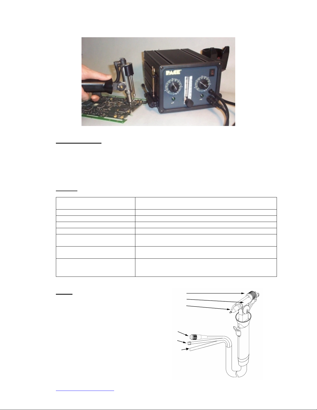
5. Set-Up
A. Hand-piece
1. Gas Heater
2. Desoldering Head Housing
3. Desoldering Tip
4. 24 Volt input, turn clockwise to engage
5. Gas connector, turn clockwise to engage
6. Vacuum Line, connect to condenser
thermal shock and contact time.
left on pads, more consistent finish.
Reduces cleaning frequency and allows for large jobs to be
completed quickly.
Easily adapts to a wide variety of jobs
1
2
3
4
5
6
www.paceworldwide.com
Page 2 of 10
Page 3
VF 90 System Operations Manual, Rev B
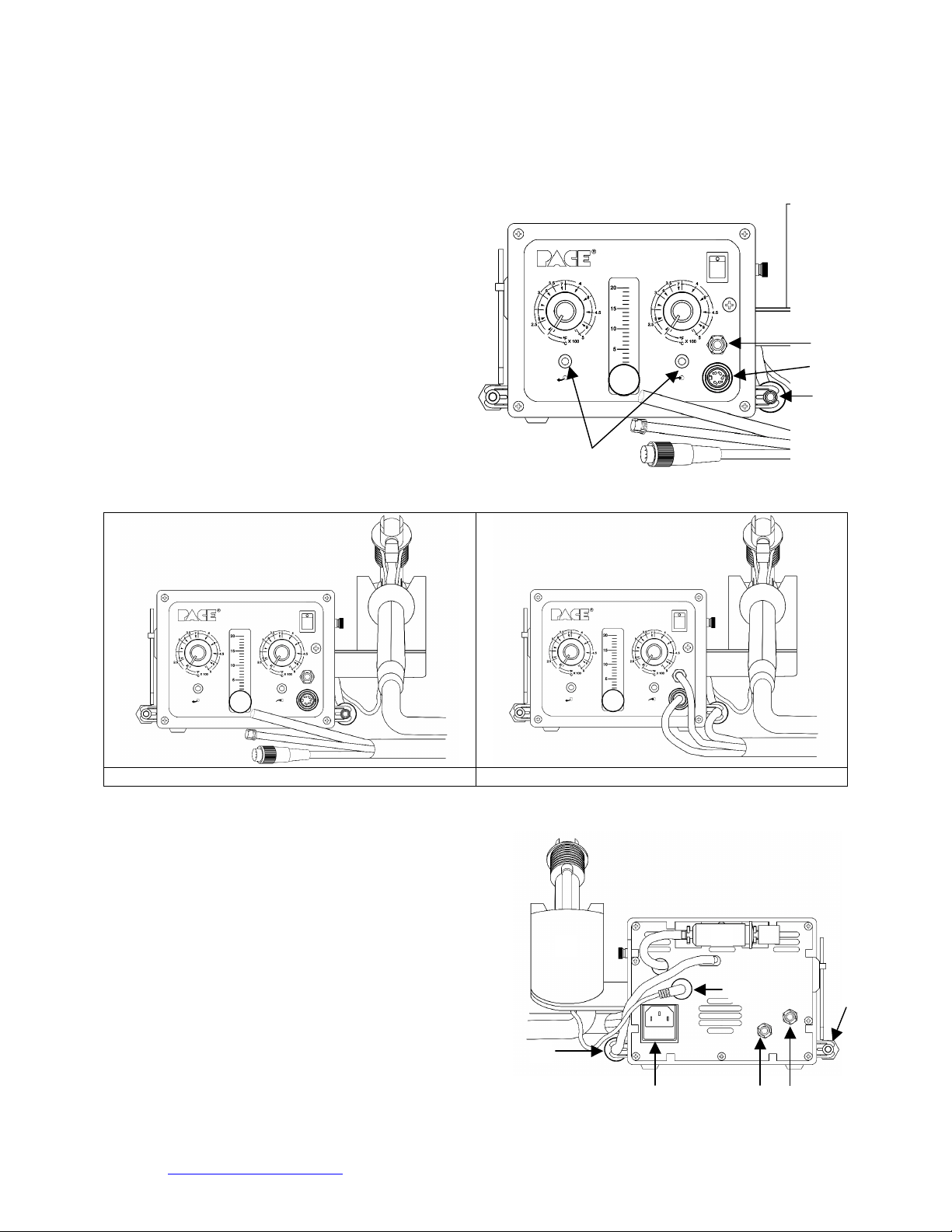
B. Power Supply (Front)
Hand Tool Connectors must be turned clockwise to engage.
1. 24 volt hand-piece connection
2. Air flow connection
3. Condenser and vacuum hose
connection
4. Tip temp adjust
5. Hot gas temp adjust
6. Airflow regulator
7. Power switch
8. Temperature indicating LEDs
5
6
4
7
2
1
3
8
VF 90 Hand-piece not connected to power supply VF 90 Hand-piece connected to power supply
C. Power Supply (Back)
1. Condenser (Back)
2. Power input
3. Silencer
4. Cleaning tool
5. Tool stand micro switch connection
6. Hand-piece cubby
7. Airflow supply
8. Vacuum supply
6
3
5
www.paceworldwide.com
Page 3 of 10
1
2
8
7
4
Page 4

VF 90 System Operations Manual, Rev B
6. Operation
(Vacuum)
Ideal air pressure input:
60 to 90 psi 13 psi max.
413.7 – 620.5 KPA 5 SCFH
4.1 – 6.2 bar 2.4 L/min
Ideal Gas Input (Air Flow)
(color-coded sleeve):
1. Turn on power switch. The heater indicator (green LEDs) will light
up. Hot Gas & Vacuum will activate if tool is removed from the
holder.
Note: Hand-piece should always be placed in holder when not
use. Hot gas flow will stop when tool is placed in the
holder
2. Adjust temperature settings for hot gas and tip to the desired setting
325°C – 375°C (600°F - 700°F). The heater indicator will remain
on until the appropriate heater reaches the set temperature. A
blinking heater indicator means set temperature has been achieved
and is being maintained.
3. Adjust airflow regulator to desired setting.
CAUTION: If airflow is too high, molten solder may be blown off of the PCB
4. Place tip close to working area.
5. When solder melts, press trigger to remove solder.
6. If the tip clogs, use the cleaning shaft from the cleaning tool by unscrewing it as shown
below.
7. Use the cleaning shaft to remove the
obstruction. While using the cleaning shaft, activate the
vacuum pulses rather than continuous suction.
7. Hand-piece Head Adjustment
A. Adjustment of angular orientation should be done while the tool is cool.
in
1. To tilt the head assembly, loosen (2) adjustment
screws.
2. Tilt the head assembly to desired position
3. Retighten screws.
B. Head rotation should be done while the tool is cool.
1. While handpiece is in the cubby, push handle down and twist.
Adjustment Screws
www.paceworldwide.com
Page 4 of 10
Page 5

VF 90 System Operations Manual, Rev B
A
g
A
g
p
2. Twist until head locks into 1 of its 4 positions. Twisting counter-clockwise will permit a
180° turn. Twisting clockwise will permit a 90° turn.
Note: The head assembly does not make a full 360°°°° turn.
8 Tip/Accessory Replacement
It is recommended for the operator to remove and inspect the tip daily. Replace the tip if there is
any sign of wear. Doing this will also prevent the tip from seizing onto the heater.
CAUTION: ONLY REMOVE THE TIP WHEN THE HAND-PIECE IS COOL
A Removing the Tip
4. To remove the tip, loosen air flow tube nut (A), then the retaining sleeve nut (B).
5. Remove retaining sleeve.
6. Remove tip.
B. Installing a new Tip
1. Insert tip into heater
2. Replace retaining sleeve over tip/heater
3. Check the alignment of retaining sleeve by inserting the end of the cleaning shaft
4. Tighten the retaining sleeve nut (B).
5. Tighten air flow tube nut (A)
Cleaning Shaft Handle
Use this wrench to
loosen nuts A & B
handle inside the tip
Tip
Retaining Sleeve
B
Retainin
Sleeve
Sleeve
B
Ti
Retainin
www.paceworldwide.com
Page 5 of 10
Page 6

Hole Diameter Length Part Number
2.3mm (.09”) 14mm (.55”) Focus Nozzle 6800-0028-P1
1.3mm (.05”) 10.9mm (.43”) Standard Nozzle 6800-0027-P1
9. Cleaning & Maintenance
Proper maintenance and regular cleaning are required to keep your VF 90 operating properly.
Please refer to the replacement parts table in Section 10 of this manual when ordering
replacement parts.
A. The following items should be
inspected and cleaned or replaced on
a regular basis:
•= Replace Felt Filter (6800-0032)
•= Clean Solder Cone (6800-0011)
•= Replace Mica Sheet (6800-0006).
•= Check O Rings on End Cap
Assembly and Elbow Connector.
Part numbers 6800-0053 for End
Cap and 6800-0051 for Elbow
Connector.
•= Replace worn-out Tip.
B. Flux Condenser Maintenance (6800-0001)
1. Replace felt filter (6800-0002) and foam filters (8000-0003)
2. Clean barrel housing (6800-0052) and condenser (6800-0019) with alcohol.
3. Tip wrench can be used to remove 6800-0015 filter cap.
6800-0002
6800-0015
4. If flux gets in the venturi, disconnect the flux condenser and the silencer. Flush the
venturi with alcohol. You may need to pump the alcohol through the venturi.
CAUTION: Disconnect power before opening back panel to access venturi!
VF 90 System Operations Manual, Rev B
Optional Tips
.5mm (.02”) 20.3 mm (.8”) Round Needle Tip P/N 6800-0029-P1
.3mm (.01”) 16mm (.63”) Small Oval Needle 6800-0030-P1
.5mm (.02”) 20mm (.80”) Medium Oval Needle 6800-0031-P1
6800-0049-P1
6800-0032-P1
6800-0011-P1
6800-0051-P1
Not Used
6800-0006-P1
6800-0003
6800-0003
6800-0052
6800-0019
6800-0015
www.paceworldwide.com
Page 6 of 10
Page 7

VF 90 System Operations Manual, Rev B
C. Silencer Maintenance
1. Disconnect air hose.
2. Open plastic housing (6800-0047).
3. Replace foam filters (6800-0002).
4. Close plastic housing.
5. Reattach air hose and install on back of power supply.
D. Cleaning the desoldering collection chamber and replacing the heater tube and silicon
washer in collection chamber
Always dispose of old solder in accordance with local environmental regulations.
To clean the collection chamber, remove the
end cap and dump out old solder. Using the
cleaning tool, remove the mica sheet and
clean. Replace if worn.
To clean the solder pathway, first remove the
retaining sleeve and Tip. Next, insert the
cleaning tool all the way into the opening to
remove any obstruction
To remove the heater tube, push the cleaning
tool in all the way, the heater tube will come out
of the front end and can be removed.
Remove the silicon washer using the hook on
the cleaning tool.
Replace the heater tube, flanged end out.
Insert new silicon washer into chamber. Using
the handle of the cleaning tool, with the tip
cleaner removed, press the silicon washer in to
place.
www.paceworldwide.com
Page 7 of 10
Page 8

VF 90 System Operations Manual, Rev B
E. O-Rings Replacement inside valve assembly
1. Unscrew lock nut at the end of the tool handle.
2. Remove handle cover.
3. Slide out valve assembl y while placi ng your
finger over the spring seat. BE CAREFULL
NOT TO LET THE SPRING SEAT SHOOT
OUT FROM THE HOUSING.
4. Clean all parts with alcohol only.
5. Replace the O-Ring Set, set of 3 (6800-0007).
6. Lubricate new O-Rings with 6800-0040 O-Ring
lubricant.
7. Make sure wires and hoses are not pinched or
kinked.
8. Reassemble hand-piece.
www.paceworldwide.com
Page 8 of 10
Page 9

10. Major Replacement Parts
Part Name Part Number
Felt Filter (Set of 10) 6800-0002-P1 Medium Oval
Foam Filter (Set of
10)
End Cap Assembly
(Standard)
High Performance
Filter Assembl y
Mica-Sheets (set of
12)
O-Ring set of Valve
Assembly
O-Ring for Heater
Bushing Eend Cap
Retaining Sleeve 6800-0009-P1 Silicone Washer 6800-0038-P1
Solder Cone 6800-0011-P1 O-Ring Lube 6800-0040-P1
Heating Element for
Tip Heater
Poppet and o-ring 6800- 001 3-P1 Meter 6800-0042-P1
Spring 6800-0014-P1 Thermocouple 1 6800-0043-P1
End Cap for Filter 6800-0015-P1 Thermocouple 2 6800-0044-P1
Valve Assembly 6800-0016-P1 Thermoprobe 1 6800-0045-P1
Transformer 6800-0017-P1 Thermoprobe 2 6800-0046-P1
Flux Condenser for
cooling fan
Heating Element for
Hot Gas
Circuit Board for
Cooling Fan
Soldenoid Valve 6800-0022-P1 Silencer 6800-0050-P1
Fan Assembly 6800-0023-P1 O-Ring for Elbow
Circuit Board for Left
(hot-gas) Side
Circuit Board for
Right (tip) Side
Handpiece Tool (VF-
90)
Standard Tip 6800-0027-P1 Tip Cleaning Shaft 6800-0057-P1
Focus Nozzle 6800-0028-P1 Air Hoses 6800-0058-P1
Long Reach Needle
Nozzle
Small Oval Nozzle 6800-0030-P1
VF 90 System Operations Manual, Rev B
6800-0003-P1 Filter Set for
6800-0004-P1 Vacuum Generator 6800-0033-P1
6800-0005-P1 Fuse Domestic,
6800-0006-P1 Fuse Export, 1.6A
6800-0007-P1 Tip Wrench 6800-0036-P1
6800-0008-P1 Cleaning Tool 6800-0037-P1
6800-0012-P1 Hot Tube 6800-0041-P1
6800-0019-P1 Plastic Housing 6800-0047-P1
6800-0020-P1 Foam Cylinder 6800-0048-P1
6800-0021-P1 End Cap Assembly 6800-0049-P1
6800-0024-P1 Barrel Filter
6800-0025-P1 Adjustment Tool 6800-0054-P1
6800-0026-P1 Wrench 6800-0056-P1
6800-0029-P1 End Cap O-Ring 6800-0059-P1
Part Name Part Number
6800-0031-P1
Nozzle
6800-0032-P1
handtool
6800-0034-P1
3.15A Fast Acting
6800-0035-P1
Fast Acting
6800-0051-P1
Connector Cap
6800-0052-P1
Housing
www.paceworldwide.com
Page 9 of 10
Page 10

VF 90 System Operations Manual, Rev B
11. Compliance
PACE Incorporated retains the right to make changes to specifications contained herein at any
time, without notice.
PACE products meet or exceed all applicable military and civilian EOS/ESD, temperature
stability and other specific a tions , inc lud ing MIL-Std-2000, ANSI/J- Std-0 01, and IPC-A-610.
Complies with MIL-S-45743E, MIL-STD-2000, DOD-STD-2000-1B, WS6536E and ESD SPEC,
DOD-STD-1686, DOD-HDBK-263
12. Service
For any questions regarding this Operation & Maintenance Manual, contact your local
authorized PACE distributor or contact PACE directly at the appropriate address listed below.
Please contact PACE or your Local Representative for service and repair.
www.paceworldwide.com
PACE USA PACE Europe
9893 Brewers Court Sherbourne House
Laurel, MD 20723 Sherbourne Drive
USA Tilbrook, Milton Keynes
MK7 8HX
United Kingdom
Tel: (301) 490-9860 (44) 1908-277666
Fax: (301) 498-3252 (44) 1908-277777
1-888-535-PACE
www.paceworldwide.com
Page 10 of 10
 Loading...