

Page 1
TP-65
TP-65 THERMOPIK HANDPIECE
OPERATION & MAINTENANCE INSTRUCTIONS
Page 2

PACE Incorporated retains the right to make changes to specifications
contained herein at any time, without notice.
Contact your local authorized PACE Distributor or PACE Incorporated to obtain
the latest specifications.
The following are registered trademarks and/or servicemarks of PACE
Incorporated, Laurel Maryland U.S.A. and may only be used to identify genuine
PACE products or services:
Arm-Evac, Mini-Wave, PACE, SensaTemp, Snap-Vac, Sodrtek, Sodr-XTractor, ThermoFlo, ThermoJet, ThermoTweez, ToolNet, VisiFilter
Since 1958, PACE Incorporated has provided advanced
technology training in all aspects of hand soldering, rework and
repair.
For any questions regarding the following instructions, contact your local
authorized PACE dealer or contact PACE directly at:
Toll Free: 1-888-535-7223, Fax : (301) 604-8782
PACE Incorporated
9893 Brewers Court
Laurel MD 20723-1990
© 2000 PACE Incorporated, Laurel MD. All rights reserved. Printed in the U.S.A.
Page 3

variety of FlatPacks (FPs) and Plastic Quad Flat Packs (PQFPs) in a matter of
The TP-65 uses a conductive heat transfer process which is very efficient and
which typically allows component removal at temperatures in the 316 - 343°C
temperature setting for initial use in most applications. You should determine
TP-65
THERMOPIK HANDPIECE
PACE P/N 7024-0001
OPERATION & MAINTENANCE
INSTRUCTIONS
MANUAL NUMBER 5050-0335
REV. C
INTRODUCTION
The TP-65 ThermoPik handpiece provides safe, one-handed removal of a wide
seconds. The ThermoPik is a member of the PACE SensaTemp family of
advanced SMT/Thru-Hole handpieces.
(600 - 650°F) range. PACE recommends the use of a 316°C (600°F) tip
the lowest possible removal temperature to work with on your board and
component types. A low temperature extends tip life.
NOTE
Always use this handpiece in a well ventilated area to avoid the inhalation
of fumes created by the heating of solder flux.
Remember that the ThermoPik is a component removal tool and is not
intended for installation of components. Other SensaTemp handpieces
are designed for component installation.
Page 4
HANDPIECE SETUP
Use the following procedures to set up your handpiece.
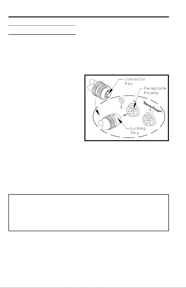
Power Receptacle Connection
Connect the handpiece power
cable plug to one of the power
receptacles on your PACE power
source. PACE recommends that
air handpieces utilize the power
receptacles closest to the AUTO
SNAP-VAC (or SNAP-VAC) and
Controllable PRESSURE Ports
to minimize cord tangles. Refer
to the Operation & Maintenance
Manual included with your power
source for details.
Air Hose Connection
There are two methods of attaching the air hose from the PACE power source
to the TP-65. Select the method which best suits your needs. The Quick
Connect Method is best suited for SensaTemp handpiece configurations where
multiple air handpieces may be in use. The Traditional Method is best suited
for single air handpiece configurations.
CAUTION
Regardless of connection method, ensure that only one air hose is
connected to the power source AUTO SNAP-VAC (or SNAP-VAC) or
Controllable PRESSURE Port at one time. Attachment to both ports
simultaneously will cause a deterioration of performance.
Page 5
QUICK CONNECT METHOD
To set up your TP-65 for the quick connect operation, perform the following steps.
1. Attach a 2.5cm length (1 inch) of clear pvc air hose (P/N 1325-0003-
07) to the metal tube in the back of the handpiece.
2. To the other end of the 2.5cm length (1 inch) clear pvc air hose attach
a female quick connect hose mount fitting (P/N 1259-0086).
3. Prepare a quick connect air hose by inserting a male quick connect
hose mount fitting (P/N 1259-0087) into each end of a 137cm (54 inch)
length of air hose. (You may already have this piece if you have other
quick disconnect handpieces configured.)
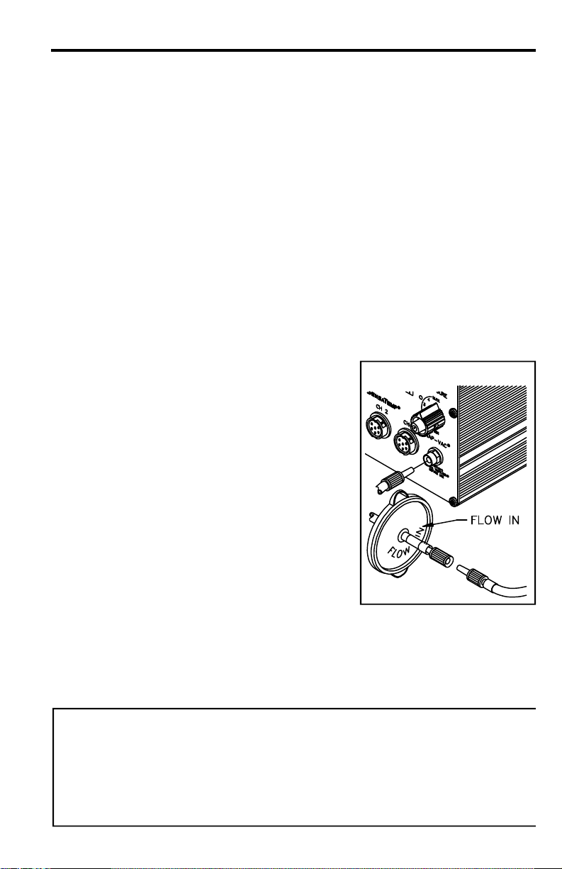
4. Prepare a VisiFilter in the following manner:
a) Connect a 2.5cm (1 inch) length of air hose to each side of the
VisiFilter.
b) To the free end of the 2.5cm (1 inch) air
hose connected to the FLOW IN side of
the VisiFilter, insert a female quick
connect hose mount fitting (P/N 1259-
0086).
b) To the free end of the 2.5cm (1 inch) air
hose connected to the FLOW OUT side
of the VisiFilter, insert a male quick
connect hose mount fitting (P/N 1259-
0087).
c) Insert the end of the male quick connect
hose mount fitting (on VisiFilter FLOW
OUT side) into the power source AUTO
SNAP-VAC (or SNAP-VAC) Port.
5. Connect the male fitting of the 137cm (54 inch) length of air hose to
the female quick connect hose mount fitting on 2.5cm (1 inch) air hose
(connected to VisiFilter) for desoldering, or into the Controllable
PRESSURE Port for hot air jet operation.
NOTE
When removing any air hose, turn and pull. Do not attempt to pull hose directly
off. Damage to or breakage of fitting or VisiFilter may occur. Use your TP65 ThermoPik with a clean VisiFilter element . Otherwise a deterioration in
performance or damage to the unit may occur.
Page 6

TRADITIONAL METHOD
1. Connect the 137cm (54 inch) length of air hose to the metal tube in
the back of the handpiece.
2. Insert a male quick connect hose mount fitting (P/N 1259-0087) to
the free end of the 137cm (54 inch) length of air hose.
3. Secure the air hose to the handpiece power cable with cable clips
(P/N 1321-0085-01).
4. Prepare a VisiFilter in the same manner as in steps 4 & 5 of the
"Quick Connect Method".
TIP SELECTION
Selection of the proper tip is essential for effective operation. Attempts to use
an improperly sized tip will result in unsatisfactory handpiece operation and
may result in lifted lands or board damage.
Table I details a partial listing of available tips. Contact your local authorized
PACE dealer for the latest Tips & Accessories Catalogue which details all
available tips.
TIP INSTALLATION
1. Carefully remove any installed vacuum cup from the TP-65 using the
tip tool and set aside.
2. Select the proper tip for your application. Refer to Table I.
3. Insert the tip shaft fully into the heater bore.
4. Using the tip tool, tighten the heater assembly set screw for a snug
fit. Do not over tighten.
5. Install the vacuum cup set aside in step #1 onto the vacuum pickup
rod. Utilize the tip tool to install the vacuum cup if the tip is hot.
NOTE
The TP-65 tips must be kept properly tinned and free of oxidation to ensure
that optimum heat transfer will take place. Refer to the "Tip Preparation"
portion of this manual.
Page 7

TIP
TIP DESCRIPTION
TIPTIP
B
A
APPLICATION
DESCRIPTION
DESCRIPTIONDESCRIPTION
FlatPack Tip
FlatPack Tip
PQFP-68 Tip
(bumper pack)
PQFP-64/80 Tip
(non-bumper pack)
PQFP-84 Tip
PQFP-100 Tip
PQFP-132 Tip
PQFP-160 Tip
PQFP-208 Tip
PQFP-196 Tip
All dimensions are nominal, inside diameters. Consult
your authorized PACE Distributor for sizes not listed
PQFP-144
PQFP-208
TIP SIZE
TIP SIZE
TIP SIZETIP SIZE
A X B
A X B
A X BA X B
15.5 x 21.6mm
(0.61 x 0.85")
16.8 x 22.9 mm)
(0.66 x 0.90")
15.7 x 15.7mm
(0.62 x 0.62")
15.7 x 15.7mm
(0.62 x 0.62")
18.3 x 18.3mm
(0.72 x 0.72")
20.8 x 20.8mm
(0.82 x 0.82")
25.9 x 25.9mm
(1.02 x 1.02")
29.2 x 29.2mm
(1.15 x 1.15")
30.0 x 30.0mm
(1.18 x 1.18")
31.0 x 31.0mm
(1.22 x 1.22")
36.3 x 36.3mm
(1.43 x 1.43")
NOTE:
PART
PART
PARTPART
NUMBER
NUMBER
NUMBERNUMBER
1121-0322-001
1121-0322-002
1121-0323
1121-0484
1121-0324
1121-0325
1121-0326
1121-0456
1121-0544
1121-0351
1121-0483
Table I. ThermoPik Tip Selection Guide
7
Page 8

TIP AND PICK ALIGNMENT
For the TP-65 to operate at its maximum efficiency (maximum heater to tip
heat transfer), the tip must be fully inserted into the heater bore and properly
secured. Due to large physical size and tip mass, the TP-65 has Tip Offset
Constants that range from 34°C (62°F) to 112°C
(201°F).
The vacuum pick assembly within the TP-65
handpiece comes factory adjusted for most
QFP components. A vacuum pick setting where
the vacuum cup makes contact with the
component body as the tip makes contact with
the component leads is the recommended
starting point. A good vacuum must be
maintained to quickly remove the component.
Use the following procedure and accompanying
illustrations if adjustment is necessary.
NOTE
The factory setting of the collars on the vacuum pick is 74mm (2.9inches)
from the end of the pick rod to the front edge of the first collar. This setting
is correct for removal of most components.
1. Using the tip tool, remove the vacuum cup and set aside.
2. Remove the handpiece rear seal and compression spring and set
aside.
3. Slide out the vacuum tube assembly and locate the two Collars.
4. Adjust the Collars in the following manner:
a) Loosen the set screw in the Collar closest to point "A" to adjust
for increased component height or the Collar closest to point "B"
for decreased component height. Adjust the Pick position for
your component. Tighten set screw to secure in position.
b) Loosen the set screw of the second Collar and adjust collar so
that the Washer is snug between the two collars yet free to
rotate. Tighten set screw to secure in position.
5. Reassemble the vacuum pick in reverse order.
Page 9

A
74mm
(2.9")
B
Page 10

TIP PREPARATION
The TP-65 tips must be kept properly tinned and free of oxidation to ensure
that optimum heat transfer will take place at all times. Tips must be kept
properly tinned and free of oxidation to ensure that optimum heat transfer will
take place.
Tin the tip using the following procedure.
1. Clean all bottom edges of the installed
tip using the P ACE fiber cleaning tool.
2. Shock the bottom edges of the installed
tip using a moist P ACE sponge tool.
3. Apply a continuous bead of solder along
the bottom edges of the installed tip.
TIP TEMPERATURE
P ACE recommends the use of a 316°C (600°F) tip temperature setting for
initial use in most applications. A low temperature extends tip life. You
should determine the lowest removal temperature to work with on your board
and component types.
Refer to the Tip & T emperature Selection System Chart (P/N 5050-0251
booklet) for your particular handpiece/tip combination. For all Dial/Display
systems, the booklet will indicate the correct Dial/Display setting for the True
Tip Temperature desired. On systems incorporating a Digital Readout, set the
desired operating temperature and Tip Offset Constant for the TP-65
handpiece/tip combination.
PCB/COMPONENT PREPARATION
Proper preparation is the key to successful component removal. Use the
following procedure to obtain optimum results.
PCB Preparation
1. Clean the component leads and PCB land areas using an approved
solvent or cleaner.
2. Ensure that the PCB is free of moisture.
3. Preheat the PCB as necessary. PCBs consisting of heat sinking
materials (e.g., ceramic, polyamide, etc.) or those with an
exceptionally heavy ground or power planes may require the use of a
preheater such as the P ACE Heat Wave.
10
Page 11

Component Preparation
1. Remove any protective coatings and clean the component leads
and land areas using an approved solvent or cleaner.
2. Ensure that the PCB is free of moisture.
3. Preheat the PCB as necessary . PCBs consisting of heat sinking
materials (e.g., ceramic, polyamide, etc.) or those with an
exceptionally heavy ground or power planes may require the use of
a preheating system such as the P ACE Heat W ave.
4. In order to maximize heat transfer from the handpiece tip to PQFP
component lead/land connections, P ACE recommends adding
bridgefill ..............
solder wrap ..........
or
flux ......................
to maximize heat transfer across
all connections.
11
Page 12

COMPONENT REMOVAL
Use the following procedure to remove the component. Ensure that the
component and board have been properly prepared (see "Board/Component
Preparation") before removing component. The technique shown is the
Bridgefill Method.
PROCEDURE
1. Ensure that all Board/
Component Preparation has
been performed.
2. St art with a tip temperature of
315°C (600°F) and adjust as
necessary.
3. Enter Tip Offset Constant for the
selected tip.
4. Install QFP Removal Tip into
ThermoPik using Tip T ool.
5. Install vacuum cup onto vacuum
pick tube using Tip Tool.
6. Remove old solder from tip with
sponge. Tin inside and bottom
edges of tip with solder.
7. Lower tip over component
contacting ALL leads with tip
(see &).
8. Confirm solder melt of ALL
joints, apply vacuum and lift
component from PCB (see
&).
12
Page 13

9. Release component onto a heat resistant surface.
10. Re-tin tip with solder and return ThermoPik to its Tip & Tool Stand.
11. Prepare lands for component replacement.
Use the SX-80 Sodr-X-Tractor handpiece to remove the old solder from the
PCB and to prepare the lands for accepting a new part. Refer to one of the
SX-80 Sodr-X-Tractor manuals for suggested solder removal techniques.
SPECIAL APPLICATIONS
If you require assistance in the use of this handpiece or require assistance
with a special application, contact PACE Product Management at:
Telephone: (301) 490 - 9860
Fax: (301) 604 - 8782
Page 14

CORRECTIVE MAINTENANCE
Your TP-65 requires no special maintenance other than being kept clean. The
heater bore and the heater assembly set screw which secures the tip must be
kept free of oxidation and debris in order to maintain the proper tip to ground
resistance. Periodically inspect the power cable, connector and handpiece
itself for evidence of physical damage. Do not use a handpiece with a
damaged power cable. Refer to Table II and the illustration following for
information on troubleshooting most handpiece problems. Table III lists the
common handpiece parts.
Use Table II and the Connector Plug illustration to determine the condition of
your TP-65 ThermoPik handpiece. Disconnect the handpiece from the PACE
power source. Use a voltmeter to check the resistance across the handpiece
Connector Plug pins as outlined in the “Checkout Procedure” column.
NOTE
The handpiece Heater Assembly must be at room temperature (22° C or
72°F) before performing "Heater Assembly Checkout Procedures".
SYMPTOM
No heat Check resistance - Pin 2 to
Handpiece
overheating
Fuse blows
when unit is
turned on
No Ground
on Tip
Pin 5. Resistance should
be 10 ohms.
If not - -
Check resistance - Pin 3 to
Pin 6.
If circuit reads open - -
Check resistance - Pin 3 to
Pin 6. Resistance should
be 110 ohms. If circuit
reads less than 105 ohms - -
Check resistance - Pin 2 to
Pin 5. Resistance should
be 10 ohms.
If not - -
Check resistance - Pin 4 to
a NEW Tip. Resistance
should be less than 2 ohms.
If not - -
CHECKOUT
PROCEDURE
CAUSE SOLUTION
Open
Heater
Open
Sensor
Shorted
Sensor
Shorted
Heater
Oxidation
buildup in
Heater Bore
Defective
Heater
Replace
Heater
Assembly
Replace
Heater
Assembly
Replace
Heater
Assembly
Replace
Heater
Assembly
Clean Heater
Bore using
appropriate
wire brush
Replace
Heater
Assembly
Page 15

Connector Plug Pin Locator
REPLACEMENT P ARTS
PART
DESCRIPTION
Replacement Handle 6993-0140
Heater Assembly 6010-0081-P1
Cord/Switch Assembly 4010-0098-P1
Rear Seal Assembly 4010-0101-P1
Tip (and Vacuum Cup) Tool 1100-0239
NUMBER
Heater Set Screw 1348-0547-P10
Vacuum Cups - - - - - - - -
4.4 mm (0.175") O.D. 1121-0382-P5
7.6mm (0.300") O.D. 1121-0383-P5
12.7mm(0.500") O.D. 1121-0384-P5
Kit (with 3 cups, 1 each size) 6993-0153-P1
SX Tip & Tool Stand 6019-0044-P1
Tip Redi-Rak 6021-0007-P1
Tip Maintenance Station 6993-0138
Table III. TP-65 Replacement Parts
Page 16

PACE USA
9893 Brewers Court
Laurel, MD 20723
U.S.A.
Tel: (301) 490-9860
1-888-535-PACE (7223)
Fax: (301) 498-3252
PACE EUROPE
Sherbourne House,
Sherbourne Drive
Tilbrook, Milton Keynes
MK7 8HX
United Kingdm
Tel: (44) 1908-277666
Fax: (44) 1908-277777
www.paceworldwide.com
 Loading...