

Ozito CMS-1810 Instruction Manual
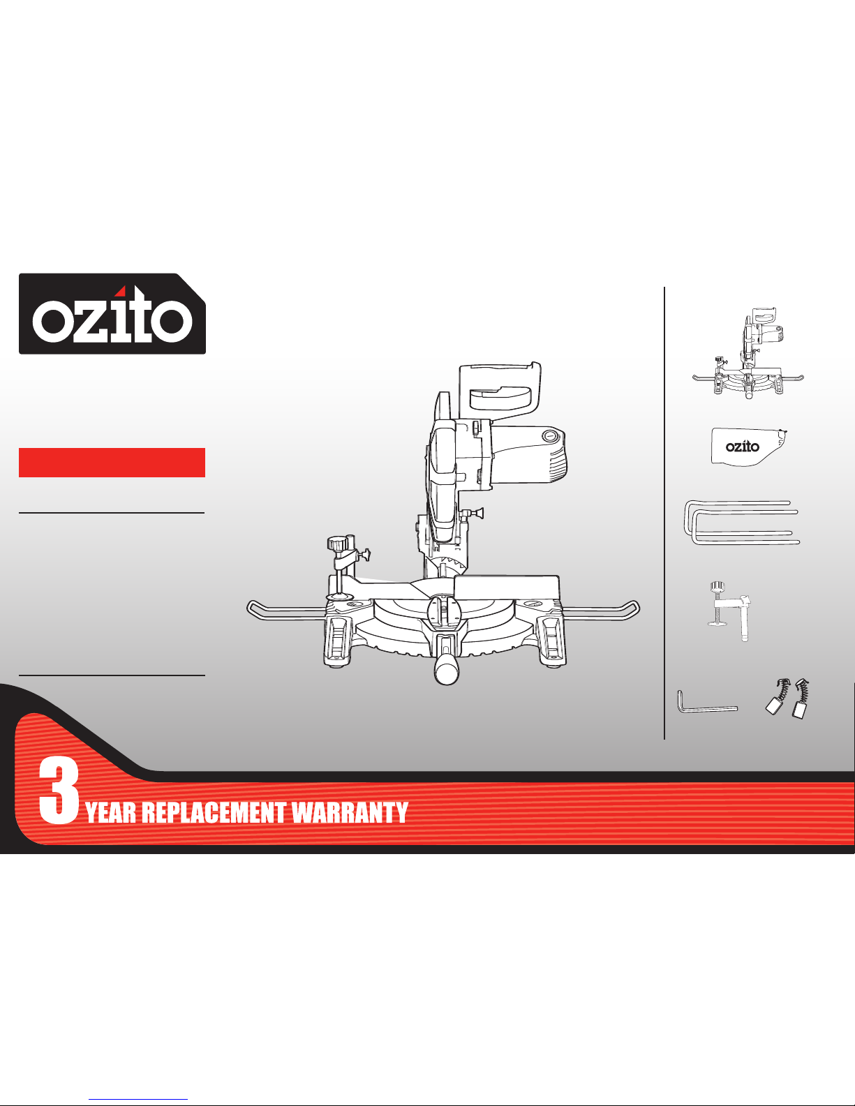
COMPOUND
MITRE SAW
255mm (10”)
INSTRUCTION MANUAL
SPECIFICATIONS
Motor: 1800W
Input: 230-240V ~ 50Hz
No Load Speed: 4,500/min
Blade: Ø255mm x 25.4 x 36T
Mitre Angle: 0-45° left & right
Bevel Angle: 0-45° left
Max. Cutting Capacity:
Mitre 0° x Bevel 90°: 75x135mm
Mitre 45°x Bevel 90°: 75x95mm
Mitre 0°x Bevel 45°: 45x135mm
Mitre 45°x Bevel 45°: 45x95mm
CMS-1810
WHAT’S IN THE BOX
Material Clamp
Compound Mitre Saw
Material Support Bars
Hex Key 6mm /
Carbon Brush Set
Dust Bag
ozito.com.au
ONLINE MANUAL
Scan this QR Code with your
mobile device to take you to
the online manual.
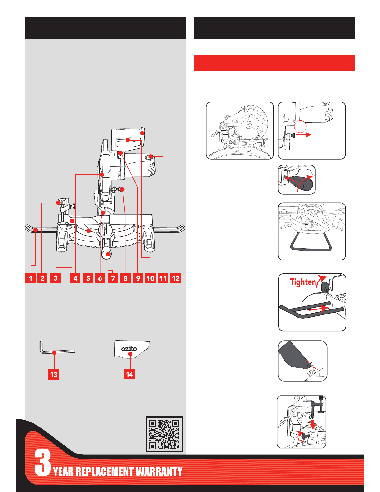
1. Material Support Bars
2. Material Clamp
3. Rear Fence
4. Retractable Safety Guard
5. Rotating Mitre Table
6. Bevel Indicator Scale
7. Mitre Lock Handle
8. Head Locking Pin
9. Spindle Lock Button
10. On/Off Switch
11. Carbon Brush Cap
12. Operating Handle
MITRE SAW
KNOW YOUR PRODUCT
1. ASSEMBLY
3. Unfold the rear stabilising
bar from the underside of the
saw and lock into position
as shown if using saw free
standing.
1. Fits over the dust
extraction port.
1. Can be mounted to the
fence, either the left or right
hand side.
2. Tighten screw on fence to
secure in place
1. Insert material support
bars into the two holes
located on both sides of
the base.
2. Tighten screw on base
to secure in place
Release cutting head from its transport position.
SETUP & PREPARATION
Material Support Bars
Dust Bag
Material Clamp
Release
2
2. Insert mitre lock handle
and tighten.
1. While holding the head of the saw down release the lock down
knob.
13. Hex Key 14. Dust Bag
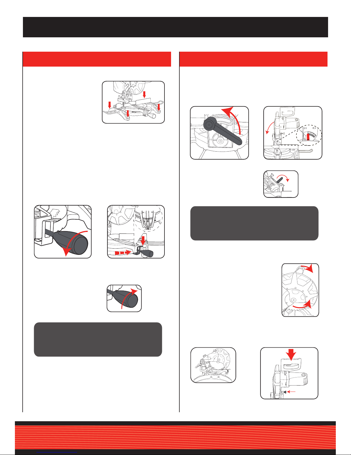
2. SET-UP AND ADJUSTMENTS
1. Loosen mitre lock
handle
1. Loosen bevel angle
lever.
2. While pressing the mitre
adjustment lever set the
desired mitre angle as shown
by the mitre angle indicator.
2. Tilt the cutting head to
the desired bevel angle as
shown by the bevel angle
indicator.
The lower guard provides protection to
your hands and limbs when the mitre
saw head is in the up position or during
the operation of the saw when the saw
is turned on and you are making a cut. It
retracts over the upper guard as the saw
is lowered into the work piece.
The lock down knob is provided for holding the cutting head down
Lock
Mitre Angle Adjustment
3. Tighten mitre lock handle
at selected angle
Bevel Angle Adjustment
0º
15º
3. Tighten bevel angle
lever at selected angle
Note: The mitre table features positive click stops at 0°, 15°, 22.5°,
30° and 45° for quick setting of common mitre angles.
Bench Mounting
The base of the saw has four
bench mounting holes that
can be used to mount it to a
workbench or mitre saw stand.
Use four screws or bolts (not
included) to secure.
Retractable Safety Guard
Transportation
Note: If required, the Mitre Saw can be mounted onto a 13mm
piece (or thicker) of plywood which can then be clamped to the
work bench or mitre saw stand. This provides the exibility to
transport the Mitre Saw to other work areas.
WARNING!: ENSURE THE MITRE LOCK HANDLE
IS TIGHT BEFORE MAKING A CUT. FAILURE TO
DO SO MAY RESULT IN THE ROTATING MITRE
TABLE MOVING DURING OPERATION AND CAUSE
SERIOUS PERSONAL INJURY.
WARNING!: ENSURE THE BEVEL ANGLE LEVER IS
TIGHT BEFORE MAKING A CUT. FAILURE TO DO
SO MAY RESULT IN THE CUTTING HEAD MOVING
DURING OPERATION AND CAUSE SERIOUS
PERSONAL INJURY.
Note: Whilst transporting or storing the mitre saw.
The saw must never be used with the lock down knob locking the
head down.
 Loading...