


Matchbox® Oven
Four Matchbox • Horno Matchbox
Models/Modèles/Modelos: M1313, M1718
Installation and Operating Ma


 nual
nual
Manuel d'installation et d'utilisation
Manual de instalación y operación
WARNING
Do not operate this equipment unless you have read and understood the contents of this manual! Failure to follow the instructions contained in this manual may result in serious injury or death. This manual contains important safety information concerning the maintenance, use, and operation of this product. If you’re unable to understand the contents of this manual, please bring it to the attention of your supervisor. Keep this manual in a safe location for future reference.
P/N 07.04.620.00
AVERTISSEMENT
Ne pas utiliser cet équipement sans avoir lu et compris le contenu de ce manuel ! Le non-respect des instructions contenues dans ce manuel peut entraîner de graves blessures ou la mort. Ce manuel contient des informations importantes concernant l'entretien, l'utilisation et le fonctionnement de ce produit. Si vous ne comprenez pas le contenu de ce manuel, veuillez le signaler à votre supérieur. Conservez ce manuel dans un endroit sûr pour pouvoir vous y référer plus tard.
Français = p 19
ADVERTENCIA
No opere este equipo al menos que haya leído y comprendido el contenido de este manual! Cualquier falla en el seguimiento de las instrucciones contenidas en este manual puede resultar en un serio lesión o muerte. Este manual contiene importante información sobre seguridad concerniente al mantenimiento, uso y operación de este producto. Si usted no puede entender el contenido de este manual por favor pregunte a su supervisor. Almacenar este manual en una localización segura para la referencia futura.
Espanõl = p 38
© 2016 Ovention, Inc.

CONTENTS |
|
English |
Important Owner Information .............................................. |
2 |
Introduction........................................................................... |
2 |
Important Safety Information............................................... |
3 |
Model Description................................................................. |
4 |
Model Designation................................................................ |
5 |
Specifications........................................................................ |
5 |
Plug Configurations............................................................. |
5 |
Electrical Rating Chart ........................................................ |
5 |
Temperature Range ............................................................ |
5 |
Dimensions ......................................................................... |
6 |
Installation ............................................................................. |
7 |
General ............................................................................... |
7 |
Operation............................................................................... |
8 |
General ............................................................................... |
8 |
menu Item Information ........................................................ |
8 |
Startup................................................................................. |
8 |
Cooking ............................................................................... |
9 |
Shutdown .......................................................................... |
10 |
Programming menu Items................................................. |
10 |
Programming a Cook Event.............................................. |
12 |
Editing Setpoint Temperatures.......................................... |
12 |
Changing Temperature Unit of measure ........................... |
13 |
Uploading from a USB Drive............................................. |
13 |
Maintenance ........................................................................ |
14 |
General ............................................................................. |
14 |
Daily Cleaning ................................................................... |
14 |
Weekly Cleaning ............................................................... |
14 |
monthly Cleaning .............................................................. |
15 |
Troubleshooting Guide ...................................................... |
16 |
Options and Accessories................................................... |
17 |
Limited Warranty................................................................. |
19 |
IMPORTANT OWNER INFORMATION
|
|
|
Record the model number, serial number, voltage, and |
Business |
|
purchase date of the unit in the spaces below (specification |
Hours: |
8:00 am to 5:00 Pm |
label located on the left side of the unit). Please have this |
|
Central Standard Time (CST) |
information available when calling Ovention® for service |
|
(Summer Hours: June to September – |
assistance. |
|
|
model No. ________________________________________ |
|
8:00 am to 5:00 Pm CST monday through Thursday |
|
8:00 am to 2:30 Pm CST Friday) |
|
Serial No. ________________________________________ |
Telephone: |
855-298-6836 (Ovention Hotline) |
Voltage __________________________________________ |
E-mail: |
partsandservice@oventionovens.com |
Date of Purchase __________________________________ |
additional information can be found |
|
by visiting our web site at www.oventionovens.com.
Need help?
Call our 24 hour, toll-free
Ovention Hotline
INTRODUCTION
Ovention matchbox® Ovens set a new standard in cooking quality, speed, flexibility, and efficiency. a new discovery in air handling not only speeds the cooking process, but “scrubs” and recirculates the air through the oven—eliminating the need for a hood system in most installations. Using icon-driven touchscreens, operators can use, edit, and develop over 1000 custom menu items. menu items can be developed to include up to three cooking stages, each with varying heat profiles, upper and lower air velocity settings, and timing.
Ovention matchbox Ovens are designed with an innovative food transport system that allows non-stop operation of the oven. a slider system with two separate cook surfaces travels back and forth into the oven chamber. One of the cook surfaces is always in the oven while the other awaits the next food item.
Ovention matchbox Ovens are products of extensive research and field testing. The materials used were selected for maximum durability, attractive appearance, and optimum performance. Every unit is inspected and tested thoroughly prior to shipment.
This manual |
provides the installation, |
safety, and |
operating |
|||
instructions |
for |
Ovention |
matchbox |
Ovens. |
Ovention |
|
recommends all |
installation, |
operating, |
and safety instructions |
|||
appearing in this manual be read prior to installation or operation |
||||||
of the oven. |
|
|
|
|
|
|
Safety information that appears in this |
manual is identified by |
|||||
the following signal word panels: |
|
|
|
|||
|
WARNING |
|
|
WARNING indicates |
a hazardous |
situation which, if not |
|
avoided, could result in death or serious injury. |
|||
|
CAUTION |
||
CAUTION indicates a hazardous |
situation which, if not |
||
avoided, could result in minor or moderate injury. |
|||
|
NOTICE |
|
|
NOTICE is used to address practices not related to personal |
|||
injury. |
|
|
|
2 |
|
Form No. OVmm-0116 |
|
|
|
|
|
|
IMPORTANT SAFETy INFORMATION |
English |
Read the following important safety information before using this .equipment to avoid serious injury or death and to avoid damage to equipment or property
WARNING
ELECTRIC SHOCK HAzARD:
• Plug unit into a properly grounded electrical receptacle of the correct voltage, size, and plug configuration. If plug and receptacle do not match, contact a qualified electrician to determine and install proper voltage and size electrical receptacle.
• Unit must be grounded properly. Failure to ground unit properly could result in serious personal injury or death.
• Turn off Standby switch, allow unit to cool, and unplug unit/turn OFF Main Disconnect switch before performing any cleaning, adjustments, or maintenance.
• DO NOT submerge or saturate with water. Unit is not waterproof. Do not operate if unit has been submerged or saturated with water.
• Unit is not weatherproof. Locate unit indoors where ambient air temperature is a minimum of 70°F (21°C).
• Do not steam clean or use excessive water on unit.
• This unit is not “jet-proof” construction. Do not use jetclean spray to clean this unit.
• Do not clean unit when it is energized or hot.
• Do not clean unit with metal scouring pads. Metal pieces can break off pad and touch electrical components, creating risk of electric shock.
• Do not pull unit by power cord.
• Keep power cord away from heated surfaces.
• Do not allow power cord to hang over edge of counter.
• Discontinue use if power cord is frayed or worn.
• Do not attempt to repair or replace a damaged power cord. Cord must be replaced by an Authorized Ovention Service Agent or a person with similar qualifications.
• This unit must be serviced by qualified personnel only. Service by unqualified personnel may lead to electric shock or burn.
• Use only Genuine Ovention Replacement Parts when service is required. Failure to use Genuine Ovention Replacement Parts will void all warranties and may subject operators of the equipment to hazardous electrical voltage, resulting in electrical shock or burn. Genuine Ovention Replacement Parts are specified to operate safely in the environments in which they are used. Some aftermarket or generic replacement parts do not have the characteristics that will allow them to operate safely in Ovention equipment.
FIRE HAzARD:
• Do not install unit on or around combustible surfaces. Discoloration or combustion could occur. Unit must be installed in non-combustible surroundings only.
• Do not use an extension cord. If power cord is too |
|
short, contact a qualified electrician to determine and |
|
install proper voltage and size electrical receptacle near |
|
unit. |
|
In the event of emergency, unplug unit (Model 1313) or turn |
|
OFF Main Disconnect switch (Model 1718). |
|
Form No. OVmm-0116 |
3 |
|
WARNING
ExPLOSION HAzARD: Do not store or use gasoline or other flammable vapors or liquids in the vicinity of this or any other appliance.
Install unit in accordance with installation instructions in this manual.
This oven is designed specifically to heat or cook—NOT for industrial or laboratory use.
Make sure all operators have been instructed on the safe and proper use of the unit.
This unit is not intended for use by children or persons with reduced physical, sensory, or mental capabilities. Ensure proper supervision of children and keep them away from the unit.
Unit may be located adjacent to a slippery floor.
This unit has no “user-serviceable” parts. If service is required on this unit, contact an Authorized Ovention Service Agent or contact the Ovention Hotline at 855-298-6836.
BURN HAzARD:
CAUTION
• Some exterior surfaces on unit will get hot. Avoid unnecessary contact with unit.
• Pan/tray will be very hot upon removal—use oven mitt, pan gripper, or other utensil to remove.
Do not turn off Main Disconnect switch or unplug unit immediately after use. Internal fans must cool oven to avoid damage to electrical components.
Locate unit at proper counter height in an area that is convenient for use. Location should be level to prevent unit or its contents from falling accidentally and strong enough to support the weight of the unit and contents.
DO NOT lift unit by platforms on each side of oven chamber. Platforms are not designed to support weight of unit. Lift from underneath oven chamber only.
Do not move or relocate unit for cleaning. Unit is bulky and heavy.
Do not place anything on top of unit; doing so may subject personnel to injury or could damage unit.
Do not heat sealed containers or products such as whole eggs in oven. These items may explode.
Use caution and be aware of pinch points when slider assembly is moving.
Do not store any materials or items inside oven chamber when not in use.
Never use steel pads, wire brushes, or scrapers to clean unit. Improper cleaning of oven could damage catalyst and will void unit warranty.
Wear protective rubber gloves and protective eyewear when cleaning unit.
IMPORTANT SAFETy INFORMATION |
|
|
|
|
|
|||||
|
|
|
English |
|||||||
|
|
|
|
|
|
|
|
|
|
|
|
|
|
|
|
|
|
||||
|
|
NOTICE |
|
|
|
NOTICE |
|
|||
Allow a minimum clearance of 1″ (25 mm) along the sides |
Use non-abrasive cleaners and cloths only. Abrasive |
|||||||||
and rear of unit for proper ventilation. Do not block or |
cleaners and cloths could scratch finish of unit, marring its |
|||||||||
cover any cabinet venting. |
appearance and making it susceptible to soil accumulation. |
|||||||||
|
|
|
|
|
|
|
|
|||
Do not cover racks or any other part of oven with metal foil. |
Clean unit daily to avoid malfunctions and maintain |
|||||||||
Airflow restriction will cause oven to overheat. |
sanitary operation. |
|||||||||
|
|
|
|
|
|
|
|
|
|
|
Do not lay unit on front or back side. Damage to unit could |
|
|
|
|
|
|||||
occur. |
|
|
|
|
|
|||||
MODEL DESCRIPTION |
|
|
|
|
|
|||||
All Models |
Operator controls consist of two touchscreens (one for each |
|||||||||
Ovention® matchbox® Ovens are designed to provide unequaled |
cooking surface), a Standby switch, and a main Disconnect switch |
|||||||||
flexibility in both kitchen and front-of-the-house installations. The |
(model m1718 only). Two removable crumb trays, one below each |
|||||||||
platform, allow for easy cleanup. a USB port allows the uploading |
||||||||||
variety of menu options, small footprint, low heat escape, and |
||||||||||
of pre-programmed menu items, installation of software updates, |
||||||||||
hood-less installation make the matchbox Oven a single solution |
||||||||||
and opportunity for service diagnostics. a 6′ (1829 mm) cord and |
||||||||||
alternative to multiple pieces of cooking equipment. |
||||||||||
plug set is standard. |
||||||||||
Each matchbox Oven is equipped with dedicated upper and lower |
||||||||||
|
|
|
|
|
||||||
heating elements and air blowers. The air blowers direct heated |
|
|
|
|
|
|||||
air through upper and lower jet plates inside the oven chamber, |
|
|
|
|
|
|||||
above and below the food. a slider assembly consisting of two |
|
|
|
|
|
|||||
separate cooking surfaces moves between the left platform, oven |
|
|
|
|
|
|||||
chamber, and right platform through the use of a drive motor and |
|
|
|
|
|
|||||
gear wheel. When one cooking surface is in the oven chamber, |
|
|
|
|
|
|||||
the other is on its corresponding platform awaiting the next food |
|
|
|
|
|
|||||
item. |
|
|
|
|
|
|||||
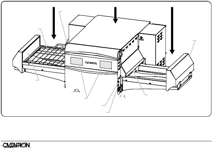
Left Platform |
Oven Chamber |
Main Disconnect |
|
Switch |
|
Cooking Rack
Slider Assembly
(Left End Cap)
Oven Door


 Touchscreens
USB Port
Standby Switch
model Description (model m1718 shown)
4
Right Platform
Platform
Cap
 Crumb
Crumb
Slider Assembly Tray
(Right End Cap)
Form No. OVmm-0116
|
|
|
MODEL DESIGNATION |
|
|
English |
|
||
|
|
|
|
|
|
|
|
|
|
|
|
|
M X X X X |
|
|
|
Oven Type |
Oven Cavity Depth (inches) |
|
|
|
M = Matchbox |
|
|
|
Oven Cavity Width (inches) |
|
|
|
|
|
|
|
|
SPECIFICATIONS
Plug Configurations
Units are equipped with an electrical cord and plug appropriate for the electrical rating of the unit. Unit must be connected to a dedicated circuit.
|
WARNING |
|
NEMA 6-30P |
NEMA 6-50P |
ELECTRIC SHOCK HAzARD: Plug unit into a properly |
||||
grounded electrical receptacle of the correct voltage, size, |
|
|
||
and plug configuration. If plug and receptacle do not |
Plug Configurations |
|||
match, contact a qualified electrician to determine and |
||||
install proper voltage and size electrical receptacle. |
NOTE: Receptacle not supplied by Ovention. |
|||
Electrical Rating Chart
Model |
Voltage |
Watts |
Amps |
m1313 |
208/240 |
5408/6960 |
26/29 |
m1313CSa |
208 |
4992 |
24 |
m1718 |
208/240 |
9152/11760 |
44/49 |
m1718CSa |
208 |
8320 |
40 |
NOTE: Ovention Matchbox Ovens are designed to accept either 208 VAC or 240 VAC. The oven will adjust automatically to the input voltage.
Phase |
Hertz |
Plug Configuration |
Unit Weight |
1 |
60 |
NEma 6-30P |
166 lbs. (75 kg) |
1 |
60 |
NEma 6-30P |
166 lbs. (75 kg) |
1 |
60 |
NEma 6-50P |
229 lbs. (102 kg) |
1 |
60 |
NEma 6-50P |
229 lbs. (102 kg) |
NOTE: The specification label is located on the left side of the unit. See the label for the serial number and verification of unit electrical information.
Temperature Range
The operating temperature range of the oven is 300°–525°F (149°–274°C).
Form No. OVmm-0116 |
5 |
|

|
|
SPECIFICATIONS |
|
|
|
|
|
|
|
|||
|
|
|
|
|
|
English |
|
|||||
|
|
|
|
|
|
|
|
|
|
|
|
|
|
|
|
|
|
|
|
|
|
|
|
||
|
|
Dimensions |
|
|
|
|
|
|
|
|
|
|
|
|
Overall |
Depth |
Height |
Footprint |
Footprint |
Rear |
Platform |
Body |
|
||
|
|
Model |
Width (A) |
(B) |
(C) |
Width (D) |
Depth (E) |
Width (F) |
Width (G) |
Width (H) |
|
|
|
|
m1313 |
49-7/8″ |
28-3/4″ |
20-1/4″ |
15-7/16″ |
20-7/16″ |
29″ |
16-15/16″ |
16-1/16″ |
|
|
|
|
|
(1266 mm) |
(730 mm) |
(514 mm) |
(391 mm) |
(518 mm) |
(735 mm) |
(430 mm) |
(408 mm) |
|
|
|
|
m1718 |
61-3/4″ |
34-1/2″ |
20-1/4″ |
19-5/16″ |
26″ |
32-15/16″ |
|
20-7/8″ |
20″ |
|
|
|
|
(1567 mm) |
(876 mm) |
(514 mm) |
(490 mm) |
(659 mm) |
(835 mm) |
(530 mm) |
(508 mm) |
|
|
|
|
|
|
|
|
|
|
|
|
|
|
|
|
|
|
|
A |
|
|
|
|
B |
|
|
|
C
 D
D 
Front View
Power Cord
 F
F 
Specification Label on left side of unit.
 E
E 
Side View
Cook Surface Dimensions
Model M1313
13″ W x 13″ D x 3-1/8″ H (330 x 330 x 79 mm)
Model M1718
17″ W x 18″ D x 3-1/8″ H (431 x 457 x 79 mm)
 G
G 
 H
H 
 G
G 
Top View
Dimensions (model m1718 shown)
6 |
Form No. OVmm-0116 |
|
English |
|
INSTALLATION |
|
General |
|
|
7. Install a crumb tray underneath each platform. |
Ovention® |
matchbox® |
Ovens are shipped with most |
• Slide the tray underneath the platform and into the tray |
components pre-assembled. Care should be taken when |
support against the oven chamber. |
||
unpacking the shipping carton to avoid damage to the unit and |
• Position the two hooks on the tray into the holes at the |
||
components enclosed. |
|
||
|
end of the platform. |
||
|
|
|
|
|
|
WARNING |
|
ELECTRIC SHOCK HAzARD: Unit is not weatherproof. |
|
||
Locate unit indoors where ambient air temperature is a |
Right Platform |
||
minimum of 70°F (21°C). |
|||
|
|
|
|
FIRE HAzARD: Do not install unit on or around combustible |
|
||
surfaces. Discoloration or combustion could occur. Unit |
|
||
must be installed in non-combustible surroundings only. |
|
||
|
|
CAUTION |
Crumb Tray |
|
|
Hook |
|
Locate unit at proper counter height in an area that is |
|||
|
|
|
|
convenient for use. Location should be level to prevent |
|
||
unit or its contents from falling accidentally and strong |
|
||
enough to support the weight of the unit and contents. |
|
||
NOTICE
Do not lay unit on front or back side. Damage to unit could occur.
NOTE: Due to the size and weight of the Matchbox Oven, use the proper number of people for installation based on the weight of the oven.
1. Inspect the shipping container for obvious signs of transit damage. If damaged, inform the freight company immediately. CAUTION! Stop! Do not attempt to use oven if damaged. Contact Ovention for assistance.
2. Cut and remove the shipping bands from around the oven packaging.
3. Remove tape and protective packaging from all surfaces of the unit.
4. Remove cooking racks and crumb trays from packaging. 5. Inspect the oven for freight damage such as dents in the end caps or inside the oven chamber. If damaged, inform
the freight company immediately.
CAUTION
DO NOT lift unit by platforms on each side of oven chamber. Platforms are not designed to support weight of unit. Lift from underneath oven chamber only.
6. Place the unit in the desired location. make sure to lift from underneath the front and rear of the oven chamber only.
• Locate the unit in an area where the ambient air temperature is constant and a minimum of 70° F (21° C).
• make sure the unit is at the proper counter height in an area convenient for use.
• make sure the countertop/table is level and strong enough to support the weight of the unit and food product.
• Position the unit with a minimum 1” (25 mm) clearance at the back and on either side for proper venting.
• make sure all the feet on the bottom of the unit are positioned securely on the countertop/table.
Form No. OVmm-0116 |
7 |
|
uBotto |
|
C |
|
r |
m |
m |
|
b |
|
|
T of |
|
r |
|
ay |
Tray
Support
Installing a Crumb Tray
8. Install a cooking rack onto each cooking surface of the slider assembly.
• move the slider assembly manually to install the racks.
 Cooking
Rack
Rack |
|
Support |
Rack |
|
Support |
Installing a Cooking Rack
9. Plug the unit into a properly grounded electrical receptacle of the correct voltage, size, and plug configuration. See the SPECIFICaTIONS section for details.
NOTE: The oven is suitable for either 208 VAC or 240 VAC and will adjust automatically to the voltage being supplied.

OPERATION |
|
|
|
|||
|
|
English |
||||
|
|
|
|
|
|
|
General |
3. Touch the desired setpoint temperature on the left |
|||||
Use the following information and procedures to operate an |
touchscreen. |
|
|
|||
Ovention® matchbox® oven. |
• The slider assembly will move to its default position, if it |
|||||
NOTE: Model 1313 ovens are designed for pan sizes up to a |
is not already there. |
|
|
|||
• The oven heaters, air blowers, and cooling fans will start |
||||||
standard 1/4-size sheet pan (9″W x 13″D [229 x 330 mm]). |
||||||
Model 1718 ovens are designed for pan sizes up to a |
up. allow 10–15 minutes for the oven to reach setpoint |
|||||
standard 1/2-size sheet pan (13″W x 18″D [330 x 457 mm]). |
temperature. |
|
|
|||
|
|
|
• The left touchscreen shows the selected setpoint |
|||
|
WARNING |
|
||||
|
|
temperature and the current cavity temperature. |
||||
Read all safety messages in the IMPORTANT SAFETy |
• The right touchscreens shows the selected setpoint |
|||||
INFORMATION section before operating this equipment. |
temperature and the estimated time remaining to reach |
|||||
In the event of emergency, unplug unit (Model 1313) or turn |
setpoint temperature. |
|
|
|||
OFF Main Disconnect switch (Model 1718). |
LEFT TOUCHSCREEN |
RIGHT TOUCHSCREEN |
||||
|
|
|
||||
|
|
|
|
|
||
|
CAUTION |
|
|
|
|
|
BURN HAzARD: Some exterior surfaces on unit will get |
|
|
|
|||
hot. Avoid unnecessary contact with unit. |
|
|
|
|||
Use caution and be aware of pinch points when slider |
|
|
|
|||
assembly is moving. |
|
|
|
|||
Menu Item Information |
Touch to return to Startup Screens and select a |
|||||
matchbox Ovens are designed to provide unequaled flexibility |
different setpoint temperature. |
|||||
|
|
|
||||
and efficiency. Each oven has the capability of storing 1024 |
|
|
|
|||
Preheat Screens |
||||||
custom menu items. menu items can be organized into |
||||||
When the oven reaches setpoint temperature, the oven begins |
||||||
Categories that group together similar items, such as different |
||||||
varieties of pizza. a total of 128 Categories can be created, with |
a temperature stabilizing period (a countdown screen appears). |
|||||
each Category able to contain 128 specific menu items. all |
|
|
|
|||
Categories and/or menu items appear on the main Recipes |
|
|
|
|||
screen. |
OVEN TEMPERATURE STABILIZING |
|||||
NOTE: It is not necessary to use Categories. The oven can be |
|
|
|
|||
set up using specific menu items only. |
5:00 |
|
||||
at initial startup, the main Recipes screen will show either |
|
|||||
sample menu items or customer-specific, preloaded menu |
|
|
|
|||
items. If the main Recipes screen shows sample menu items, |
TIME REMAINING |
|||||
these menu items can be used to help develop specific menu |
||||||
|
|
|
||||
items appropriate for the installation. Refer to the “Programming |
|
|
|
|||
menu Items” procedure in this section for instructions on |
|
|
|
|||
creating menu items. |
|
|
|
|||
Startup |
Oven Stabilizing Screen |
|||||
|
|
|
||||
1. On model m1718, make sure the main Disconnect switch |
after the oven temperature stabilizes, the main Recipes screen |
|||||
appears on one of the touchscreens, dependent upon the location |
||||||
is in the ON (I) position. |
of the slider assembly. The oven is now ready for cooking. |
|||||
2. move the Standby switch up to the “On” position. |
LEFT TOUCHSCREEN |
RIGHT TOUCHSCREEN |
||||
• The touchscreens will energize. One touchscreen |
||||||
|
|
|
||||
shows the available setpoint temperatures. The other |
|
|
|
|||
touchscreen shows the name of the oven and current |
|
|
|
|||
software version. |
|
|
|
|||
LEFT TOUCHSCREEN |
RIGHT TOUCHSCREEN |
|
7.12L02 - 5.14 |
Touch desired |
Touch appropriate |
setpoint |
arrow to move |
temperature. |
slider assembly. |
|
Startup Screens |
Touch arrow to move slider assembly from right-to-left and use left touchscreen.
main Recipes Screen
NOTE: The Menu items shown are for example only. Depending on the configuration of the oven, the Main Recipes screen will show either sample menu items or customer-specific, preloaded menu items.
8 |
Form No. OVmm-0116 |
|

|
|
|
|
|
|
|
|
|
|
|
|
|
|
|
|
|
|
OPERATION |
||
|
|
|
English |
|
|
|
|
|
|
|
|
|
|
|
|
|||||
|
|
|
|
|
|
|
|
|
|
|
|
|
|
|
|
|
|
|
|
|
Cooking |
|
|
|
|
|
|
|
|
|
|
• If the selected menu item contains any Cook Events, a |
|||||||||
Use the following procedures to cook a single item or cook |
Cook Event coutdown |
screen will appear on the |
||||||||||||||||||
touchscreen opposite the Cooking Screen. When the |
||||||||||||||||||||
multiple items continuously. |
|
|
|
|
|
|||||||||||||||
|
|
|
|
|
Cook Event occurs, the slider assembly will move the |
|||||||||||||||
Single Item Cooking |
|
|
|
|
|
|
|
|
|
|
||||||||||
|
|
|
|
|
|
|
|
|
|
food product out of the oven chamber. Complete the |
||||||||||
1. make sure the oven has reached setpoint temperature. The |
action on the food item, and touch RESUmE on the |
|||||||||||||||||||
|
|
main Recipes screen will appear on one of the touchscreens. |
Cook Event screen to continue the cooking sequece. |
|||||||||||||||||
|
|
setpoint |
current |
|
of Menu screens |
See “Programming a Cook Event” in this section for a |
||||||||||||||
|
|
|
detailed description of Cook Events. |
|||||||||||||||||
|
|
Indicates oven |
Indicates |
|
Indicates number |
|
|
|
|
|||||||||||
|
|
temperature. |
screen. |
|
available. |
• When the cooking sequence is finished, the |
||||||||||||||
|
|
|
|
|
|
|
|
|
|
|
|
|
|
|
|
touchscreen flashes “DONE”, an audible alert sounds, |
||||
|
|
|
|
|
|
|
|
|
|
|
|
|
|
|
|
|||||
|
|
|
|
|
|
|
|
|
|
|
|
|
|
|
|
and the slider assembly moves the food product out of |
||||
|
|
|
|
|
|
|
|
|
|
|
|
|
|
|
|
the oven chamber. |
|
|
||
|
|
|
|
|
|
|
|
|
|
|
|
|
|
|
|
|
|
|
||
|
|
|
|
|
|
|
|
|
|
|
|
|
|
|
|
|
CAUTION |
|
||
|
|
|
|
|
|
|
|
|
|
|
|
|
|
|
|
|||||
|
|
|
|
|
|
|
|
|
|
|
|
|
|
|
|
BURN HAzARD: Pan/tray will be very hot upon removal— |
||||
|
|
|
|
|
|
|
|
|
|
|
|
|
|
|
|
use oven mitt, pan gripper, or other utensil to remove. |
||||
|
|
|
|
|
|
|
|
|
|
|
|
|
|
|
|
|||||
|
|
|
|
|
|
|
|
|
|
|
|
|
|
|
|
4. Using a paddle, pan gripper, or other utensil, remove the |
||||
|
|
|
|
|
|
|
|
|
|
|
|
|
|
|
|
|||||
|
|
|
|
|
|
|
|
|
|
|
|
|
|
|
|
cooked food product. |
|
|
||
|
|
|
|
|
|
|
|
|
|
|
|
|
|
|
|
Queued Item Cooking (Continuous Cooking) |
||||
|
|
|
|
|
|
|
|
|
|
|
|
|
|
|
|
1. Perform steps 1–3 of the “Single Item Cooking” procedure |
||||
|
|
Category (Asterisk |
|
|
|
|
|
Menu Items |
in this section. |
|
|
|||||||||
|
|
|
|
|
|
|
|
|
||||||||||||
|
|
indicates a category. |
|
|
|
|
|
|
|
|
|
|
• The slider assembly moves the food product into the |
|||||||
|
|
items in Category.) |
|
|
|
|
|
|
|
|
|
|
oven chamber, and the cooking sequence begins. |
|||||||
|
|
Touch to access menu |
|
|
|
|
|
|
|
|
|
|||||||||
|
|
|
|
|
main Recipes Screen |
2. Using a paddle, pan gripper, or other utensil, place the next |
||||||||||||||
|
|
|
|
|
food product onto the opposite cooking surface that is now |
|||||||||||||||
2. Using a paddle, pan gripper, or other utensil, place the food |
||||||||||||||||||||
outside of the oven chamber. |
||||||||||||||||||||
|
|
product onto the cooking surface that is outside of the oven |
||||||||||||||||||
|
|
NOTE: If the selected menu item has any Cook Events, queued |
||||||||||||||||||
|
|
chamber. |
|
|
|
|
|
|
|
|
|
|
||||||||
|
|
|
|
|
|
|
|
|
|
|
|
item cooking will not be availble until all Cook Events |
||||||||
NOTE: The left touchscreen corresponds with the left cooking |
||||||||||||||||||||
are complete. |
|
|
||||||||||||||||||
|
|
surface/platform, and the right touchscreen |
|
|
||||||||||||||||
|
|
3. Touch the desired menu item on the corresponding |
||||||||||||||||||
|
|
corresponds with the right cooking surface/platform. |
||||||||||||||||||
3. Touch the desired menu item on the corresponding |
touchscreen. |
|
|
|||||||||||||||||
• The touchscreen changes to the Queue screen and |
||||||||||||||||||||
|
|
touchscreen. |
|
|
|
|
|
|
|
|
|
|
||||||||
|
|
• The slider assembly moves the food product into the |
shows the queued menu item, the queued item cook |
|||||||||||||||||
|
|
time, and the total time remaining until the queued item |
||||||||||||||||||
|
|
oven chamber, and the cooking sequence begins. |
||||||||||||||||||
|
|
is done. |
|
|
||||||||||||||||
|
|
• The touchscreen changes to the Cooking screen and |
|
|
||||||||||||||||
|
|
LEFT TOUCHSCREEN |
RIGHT TOUCHSCREEN |
|||||||||||||||||
|
|
shows the remaining cook time for the selected menu item. |
||||||||||||||||||
|
|
|
|
|
|
|
|
|
|
|
|
|
|
|
|
|||||
|
|
Touch to show settings for active menu item. |
|
|
|
|
|
|
||||||||||||
|
|
|
|
|
|
|
||||||||||||||
|
|
|
|
|
Indicates remaining cook time. |
|
|
|
|
|||||||||||
|
|
|
|
|
|
|
|
|
||||||||||||
|
|
|
|
|
|
|
|
|
Touch to cancel current |
|
|
Touch to cancel |
|
|
|
|
|
|
|
|
|
|
|||
|
|
|
|
|
|
|
|
|
cooking sequence and |
|
|
queued menu item. |
|
|
|
|
|
|
|
|
|
start queued menu item. |
|
|
|
|
|
|
|
|
|
|
|
|
Touchscreens During Queued Item Cooking |
|||
|
|
|
|
|
|
|
|
• When the first cooking sequence has 10 seconds |
||||
|
|
|
|
|
|
|
||||||
|
|
|
|
|
|
|
|
|
remaining, the Queue screen flashes yellow to indicate |
|||
|
Touch to pause cooking sequence. Slider assembly |
|
|
that the slider assembly is about to move. |
||||||||
|
||||||||||||
|
moves food product out of oven chamber. On the |
|
• When the first cooking |
sequence is complete, the |
||||||||
|
to oven chamber or CANCEL to cancel cooking. |
|
|
corresponding touchscreen flashes “DONE”, an audible |
||||||||
|
Pause screen, touch RESUME to return food product |
|
|
|
|
|
|
|||||
|
Cooking sequence will Auto Cancel in two minutes if |
|
|
alert sounds, and the slider assembly moves the cooked |
||||||||
|
no selection is made. |
|
|
food product out of the oven chamber while moving the |
||||||||
|
|
|
|
Cooking Screen |
|
|
queued food product into the oven chamber. |
|||||
|
|
|
|
4. Using a paddle, pan gripper, or other utensil, remove the |
||||||||
|
|
|
|
|
|
|
||||||
|
|
|
|
|
|
|
cooked food product. |
|
|
|
||
|
5. Repeat steps 2–4 of this procedure for continuous, queued |
|
item cooking. |
Form No. OVmm-0116 |
9 |
|
OPERATION |
|
|
|
|
|
|
|
|
|
|
|
|
|
|
|
|
|
|
|
|
|
||||||
|
|
|
|
|
|
|
|
|
|
|
|
|
|
|
English |
||||||||||||
|
|
|
|
|
|
|
|
|
|
|
|
|
|
|
|
|
|
|
|
|
|
|
|
|
|
|
|
Shutdown |
|
|
|
|
|
|
|
|
|
|
|
|
|
|
|
|
|
|
|
|
|
||||||
1. move the Standby switch down to the “Off” position. |
|
|
|
|
|
|
|
|
|
|
|
|
|||||||||||||||
• The oven heaters and touchscreens will shut off. |
|
|
|
|
|
|
|
|
|
|
|
|
|||||||||||||||
|
|
|
|
|
|
|
|
|
|
|
|
||||||||||||||||
• The air blowers and cooling fans will continue to operate |
|
|
|
|
|
|
|
|
|
|
|
|
|||||||||||||||
until the oven chamber temperature drops below 140°F |
|
|
|
|
|
|
|
|
|
|
|
|
|||||||||||||||
(60°C). |
|
|
|
|
|
|
|
|
|
|
|
|
|
|
|
|
|
|
|
|
|
||||||
|
|
|
|
|
|
CAUTION |
|
|
|
|
|
|
|
|
|
|
|
|
|
|
|
|
|||||
Do not turn off Main Disconnect switch or unplug unit |
|
|
|
|
|
|
|
|
|
|
|
|
|||||||||||||||
immediately after use. Internal fans must cool oven to |
|
|
|
|
|
|
|
|
|
|
|
|
|||||||||||||||
avoid damage to electrical components. |
|
|
|
|
|
|
|
|
|
|
|
|
|||||||||||||||
|
|
|
|
|
|
|
|
|
|
|
|
||||||||||||||||
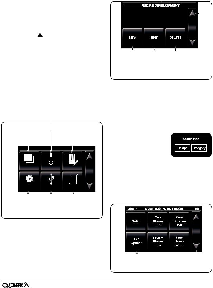
Programming Menu Items |
Touch to create |
|
Touch to delete a |
|
|
|
|||||||||||||||||||||
a new menu item/ |
|
menu item/category. |
|
||||||||||||||||||||||||
Use the following procedures to edit, create, or delete menu |
category. |
|
|
|
|
Touch to return |
|
|
|
|
|||||||||||||||||
items and categories. These procedures require access to |
|
|
|
|
|
|
|
|
|||||||||||||||||||
|
|
|
|
|
|
|
|
||||||||||||||||||||
|
Touch to edit an |
to Admin Mode |
|||||||||||||||||||||||||
password-protected screens and should be performed by |
|
||||||||||||||||||||||||||
|
existing menu item/ |
screen |
|||||||||||||||||||||||||
authorized personnel only. |
|
|
|
|
|
|
|
|
|
category. |
|
|
|
|
|
|
|||||||||||
NOTE: The USB port allows the uploading of pre-programmed |
|
Recipe Development Screen |
|||||||||||||||||||||||||
menu items from an external USB drive. Refer to the |
4. Touch NEW, EDIT, or DELETE on the Recipe Development |
||||||||||||||||||||||||||
“Uploading from a USB Drive” procedure in this section |
|||||||||||||||||||||||||||
screen, depending on the desired function. Then, refer to |
|||||||||||||||||||||||||||
for details. |
|
|
|
|
|
|
|
|
|
||||||||||||||||||
|
|
|
|
|
|
|
|
|
the appropriate procedure in this section. |
||||||||||||||||||
1. From the main Recipes screen, touch the “up” arrow. |
|||||||||||||||||||||||||||
Creating New Menu Items/Categories |
|||||||||||||||||||||||||||
• a password keypad will appear on the touchscreen. |
|||||||||||||||||||||||||||
1. after touching NEW on the Recipe Development screen, |
|||||||||||||||||||||||||||
2. Input the password using the keypad, and touch ENTER. |
|||||||||||||||||||||||||||
the New Recipe/Category screen will appear. This screen |
|||||||||||||||||||||||||||
• The admin mode screen will appear on the touchscreen. |
will look like the main Recipes Screen. |
||||||||||||||||||||||||||
2. Touch an empty box. The “Select Type” window will appear. |
|||||||||||||||||||||||||||
|
|
|
|
|
Touch to access |
||||||||||||||||||||||
|
|
|
|
|
If no empty boxes are available, touch the “down” arrow to |
||||||||||||||||||||||
|
|
|
Edit Setpoint Data screen. |
||||||||||||||||||||||||
|
|
|
scroll to the next screen. |
|
|
|
|
|
|
|
|
|
|||||||||||||||
|
|
|
|
|
|
|
|
|
|
Touch to access |
|
|
|
|
|
|
|
|
|
||||||||
Touch to return to |
|
|
|
|
3. Touch RECIPE to create a new |
|
|
|
|
|
|
|
|||||||||||||||
|
|
|
Recipe Development |
|
|
|
|
|
|
|
|||||||||||||||||
Main Recipes screen. |
|
|
|
screen. |
menu item or CaTEGORy to |
|
|
|
|
|
|
|
|||||||||||||||
465 |
F |
|
ADMIN MODE |
|
|
|
create a new category. |
|
|
|
|
|
|
|
|
|
|||||||||||
|
|
|
|
• For new menu items, the |
|
|
|
|
|
|
|
||||||||||||||||
|
|
|
|
|
|
|
|
|
|
|
|
|
|
|
|
|
|
|
|
|
|
||||||
|
|
|
|
|
|
|
|
|
|
|
|
|
|
|
New Recipe Settings Screen |
|
|
|
|
|
|
|
|||||
|
|
|
|
|
|
|
|
|
|
|
|
|
|
|
|
|
|
|
|
|
|
||||||
|
|
|
|
|
|
|
|
|
|
|
|
|
|
|
will appear. |
|
|
|
|
|
|
|
|
|
|||
|
|
|
|
|
|
|
|
|
|
|
|
|
|
|
|
|
|
|
|
|
|
|
|
||||
|
|
|
|
|
|
|
|
|
|
|
|
|
|
|
|
|
|
|
|
|
|
|
|
||||
|
Back |
|
Temps |
Recipes |
• For new categories, a keypad appears. Type the name |
||||||||||||||||||||||
|
|
of the new category, then touch ENTER. The Recipe |
|||||||||||||||||||||||||
|
|
|
|
|
|
|
|
|
|
|
|
|
|
|
Development screen reappears. To add menu items to |
||||||||||||
|
|
|
|
|
|
|
|
|
|
|
|
|
|
|
the new category: |
|
|
|
|
|
|
|
|
|
|||
|
|
|
|
|
|
|
|
|
|
|
|
|
|
|
a. Touch NEW on the Recipe Development screen. |
||||||||||||
|
Maint |
|
USB |
|
Logs |
b. Touch the new category that is now available on the |
|||||||||||||||||||||
|
|
|
|
|
|
|
|
|
|
|
|
|
|
|
New Recipe/Category screen. |
|
|
|
|
|
|
||||||
|
|
|
|
|
Touch to |
|
access |
|
|
c. Touch an empty box in the new category and continue |
|||||||||||||||||
|
|
|
|
|
|||||||||||||||||||||||
|
|
|
|
|
USB Functions |
|
|
with the next step in this procedure. |
|||||||||||||||||||
Touch to |
|
access |
screen. |
Touch to |
|
access |
|
|
|
|
|
|
|
|
|
|
|
|
|||||||||
|
|
|
|
|
|
|
|
|
|
|
|
|
|
||||||||||||||
Maintenance Mode |
|
|
|
|
Logs Detail |
|
|
|
|
|
|
|
|
|
|
|
|
||||||||||
screen. admin mode Screenscreen. |
|
|
|
|
|
|
|
|
|
|
|
|
|||||||||||||||
3. Touch RECIPES to access the Recipe Development screen.
|
|
|
|
|
|
|
|
Touch to save settings, |
Touch to |
access |
|
cancel settings, perform a |
settings for |
||
Test Cook, and return to |
next stage, |
||
Recipe Development screen. |
if required. |
||
|
New Recipe Settings Screen |
10 |
Form No. OVmm-0116 |
|
English |
OPERATION |
4. Touch each “setting” box on the New Recipe Settings screen to edit the corresponding setting. Settings include item name, top blower percentage, bottom blower percentage, cook duration, and cook temperature.
• Touching a “setting” box will bring up a keypad specific to the setting. Enter the desired value using the keypad, then touch ENTER to return to the New Recipe Settings screen.
• menu item names can have up to 16 characters.
• Touch the “down” arrow to access the settings for stages 2 and 3. Each menu item can be programmed to have up to three stages, depending on the food product. Stages are programmed with unique settings to create a customized cooking sequence for the menu item.
NOTE: It is not necessary to create stages for a menu item if it is not required by the food product. If unique stages are not required, leave the cook time setting for stages 2 and 3 at zero.
5. When programming is complete, touch EXIT OPTIONS on the New Recipe Settings screen.
a. The Recipe Dev Exit Options screen will appear.
b. Touch the desired option: EXIT aND SaVE, EXIT (without saving), CONTINUE EDITING, or TEST COOk.
• If one of the “EXIT” options was touched, the Recipe Development screen appears. If all programming is complete, touch the “up” arrow to return to the admin mode screen.
• To program additional menu items, repeat the appropriate steps of this procedure.
Editing Menu Items/Categories
1. after touching EDIT on the Recipe Development screen, the Edit Recipe/Category screen will appear. This screen will look like the main Recipes screen.
2. To edit a menu item, touch the desired menu item, and the Edit Recipe Settings screen will appear.
3. To edit a category, touch the desired category. The “Edit Category” window will appear.
• Touch RECIPE to edit a menu item in the selected category. Touch the desired menu item,
and the Edit Recipe Settings screen will appear. Continue with the next step in this procedure.
• Touch NamE to rename the selected category using the keypad that appears, then touch ENTER. The Recipe Development screen reappears. Renaming is complete.
Form No. OVmm-0116 |
11 |
|
|
|
|
|
|
|
|
|
Touch to save settings, |
Touch to |
access |
|
cancel settings, perform a |
settings for |
||
Test Cook, and return to |
next stage, |
||
Recipe Development screen. |
if required. |
||
Edit Recipe Settings Screen
4. Touch each “setting” box on the Edit Recipe Settings screen to edit the corresponding setting. Settings include item name, top blower percentage, bottom blower percentage, cook duration, and cook temperature.
• Touching a “setting” box will bring up a keypad specific to the setting. Enter the desired value using the keypad, then touch ENTER to return to the Edit Recipe Settings screen.
• menu item names can have up to 16 characters.
• Touch the “down” arrow to access the settings for stages 2 and 3, if necessary.
NOTE:It is not necessary to create stages for a menu item if it is not required by the food product. If unique stages are not required, leave the cook time setting for stages 2 and 3 at zero.
5. When editing is complete, touch EXIT OPTIONS on the corresponding Edit Recipe/Category screen.
a. The Recipe Dev Exit Options screen will appear.
b. Touch the desired option: EXIT aND SaVE, EXIT (without saving), CONTINUE EDITING, or TEST COOk.
• If one of the “EXIT” options was touched, the Recipe Development screen appears. If all editing is complete, touch the “up” arrow to return the admin mode screen.
• To edit additional menu items, repeat the appropriate steps of this procedure.
Deleting Menu Items/Categories
1. after touching DELETE on the Recipe Development screen, the Delete Recipe/Category screen will appear. This screen will look like the main Recipes screen.
2. Touch the desired menu item or category to delete. The “Delete This Entry?” window will appear.
• Touch yES to delete the menu item or category. The Recipe Development screen reappears.
• Touch NO to return to the
Recipe Development screen without deleting.
3. When deleting is complete, touch the “up” arrow to return the admin mode screen

OPERATION |
|
|
|
|
|
|
|
|
|
|
|
|
|
|
|
|
English |
||
|
|
|
|
|
|
|
|
|
|
Programming a Cook Event |
1. From the main Recipes screen, touch the “up” arrow. |
||||||||
a Cook Event is a feature that can be programmed into menu |
• a password keypad will appear on the touchscreen. |
||||||||
items that allows an action to be taken on a food product during |
2. Input the password using the keypad, and touch ENTER. |
||||||||
a cooking sequence (example: aDD CHEESE). a Cook Event |
• The admin mode screen will appear on the touchscreen. |
||||||||
pauses an in progress cooking sequence and signals the slider |
|||||||||
assembly to move the food product out of the oven chamber. |
|
|
|
|
Touch to access |
||||
after the action is taken on the food product, the slider |
|
|
|
Edit Setpoint Data screen. |
|||||
assembly moves the product back into the oven chamber and |
|
|
|
|
|
|
Touch to access |
||
the cooking sequence resumes. Up to two Cook Events can be |
|
|
|
|
|
|
|||
programmed into a menu item. Use the following procedure to |
Main Recipes screen. |
|
screen. |
||||||
|
Touch to return to |
Recipe Development |
|||||||
program a Cook Event. |
465 |
|
F |
ADMIN MODE |
|
|
|||
|
|
|
|||||||
1. Follow the procedure for creating or editing a menu item |
|
|
|
||||||
described earlier in this section. |
|
|
|
|
|
|
|
|
|
|
|
|
|
|
|
|
|
|
|
2. after programming the settings for the desired number of |
|
|
|
|
|
|
|
|
|
|
|
|
|
|
|
|
|
|
|
|
|
|
|
|
|
|
|
|
|
stages on the New Recipe Settings/Edit Recipe Settings |
|
Back |
Temps |
Recipes |
|||||
screen, touch the “down” arrow to scroll past the stages to |
|
||||||||
|
|
||||||||
the Cook Event 1 screen. |
|
|
|
|
|
|
|
|
|
Touch to name or edit |
|
|
|
|
|
|
|
|
|
|
|
||
|
|
|
Touch to access |
|||
name of Cook Event 1. |
||||||
settings for |
||||||
Touch to set time into cooking |
|
Cook Event 2, |
||||
|
||||||
sequence that Cook Event will occur. |
if required. |
|||||
Cook Event 1 Screen
3. Touch the center box on the Cook Event screen to name the cook event using the keypad that appears, then touch ENTER.
4. Touch the right-side box on the Cook Event screen to set the time into the cooking sequence when the cook event should occur. Enter the desired value using the keypad, then touch ENTER.
5. If a second Cook Event is required, touch the “down” arrow to access the Cook Event 2 screen and repeat steps 3 and 4.
6. When programming is complete, touch EXIT OPTIONS. a. The Recipe Dev Exit Options screen will appear.
b. Touch the desired option: EXIT aND SaVE, EXIT (without saving), CONTINUE EDITING, or TEST COOk.
• If one of the “EXIT” options was touched, the Recipe Development screen appears. If all programming is complete, touch the “up” arrow to return to the admin mode screen.
• To program additional menu items, repeat the appropriate steps of this procedure.
Editing Setpoint Temperatures
Use the following procedure to edit or create the setpoint temperature(s) available at oven startup. This procedure requires access to password-protected screens and should be performed by authorized personnel only.
Maint USB Logs
|
|
Touch to |
|
access |
|
|
|
|
|
|
|||||
|
|
USB Functions |
|
|
|||
Touch to |
|
access |
screen. Touch to |
|
access |
||
|
|
||||||
Maintenance Mode |
|
|
Logs Detail |
||||
screen. admin mode Screenscreen.
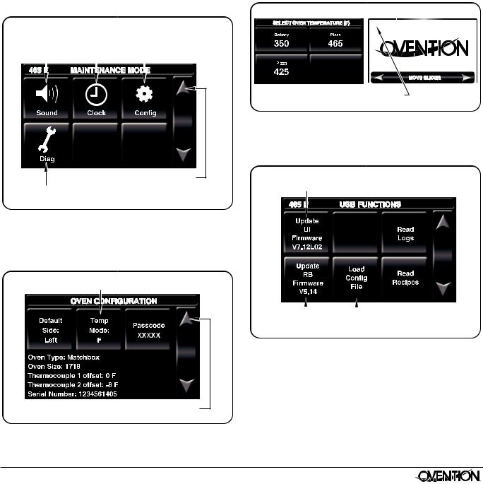
3. Touch TEmPS to access the Edit Setpoint Data screen.
• The oven can store up to three setpoint temperatures.
Unit of Measure:
F = Fahrenheit, C = Celsius 
Touch each |
|
setpoint to |
Touch |
|
to save |
|
|
||||
edit setpoint name |
and return to |
||||
and temperature. |
Admin Mode screen. |
||||
Edit Setpoint Data Screen
4. Touch the desired setpoint to edit. The “Edit Setpoint” window will appear.
• Touch TEmP to edit the setpoint temperature using the keypad that appears, then touch ENTER. The Edit Setpoint Data screen reappears.
• Touch NamE to edit the setpoint name using the keypad that appears, then touch ENTER. The Edit Setpoint Data screen reappears.
5. Repeat step 4 to edit another setpoint name/temperature.
12 |
Form No. OVmm-0116 |
|
6. When the setpoint temperature changes are complete, |
Uploading from a USB DriveOPERATION |
|||
English |
|
|
|
|
|
|
|
|
|
touch EXIT aND SaVE to return to the admin mode |
Use the following procedure to upload pre-programmed menu |
|||
screen. |
||||
items or firmware updates from an external USB drive. This |
||||
• If programming is complete, touch BaCk to return to |
procedure requires access to password-protected screens and |
|||
the main Recipes screen. |
should be performed at oven startup by authorized personnel only. |
|||
Changing Temperature Unit of Measure |
NOTE: USB drive must have a capacity of 4 GB or less. |
|||
Use the following procedure to change the temperature unit of |
1. move the Standby switch up to the “On” position. |
|||
measure between fahrenheit and celsius. This procedure |
• The touchscreens will energize. One touchscreen shows |
|||
requires access to password-protected screens and should be |
||||
the available setpoint temperatures. The other |
||||
performed by authorized personnel only. |
||||
touchscreen shows the name of the oven and current |
||||
1. From the main Recipes screen, touch the “up” arrow. |
software version. |
|
||
• a password keypad will appear on the touchscreen. |
2. Remove the cover from the USB port above the Standby |
|||
2. Input the password using the keypad, and touch ENTER. |
switch, and insert the USB drive into the port. |
|||
3. Touch the upper left-hand corner on the right touchscreen. |
||||
• The admin mode screen will appear on the |
||||
• a password keypad will appear on the touchscreen. |
||||
touchscreen. |
||||
3. Touch maINT to access the maintenance mode screen. |
LEFT TOUCHSCREEN |
RIGHT TOUCHSCREEN |
||
|
|
|
Touch to access |
||
|
|
|
Set Time/Date |
||
Touch to access |
|
screen. |
|
Touch to access |
|
Sound Settings |
|
|
|
Oven Configuration |
|
screen. |
|
|
|
||
|
|
|
screen. |
||
|
|
|
|
|
|
|
|
|
|
|
|
7.12L02 - 5.14 |
Touch to return to
Touch to access Admin Mode screen.
Diagonostics Mode
screen.
maintenance mode Screen
4. Touch CONFIG on the maintenance mode screen. The Oven Configuration screen appears.
5. Touch TEmP mODE on the Oven Configuration screen to toggle the unit of measure between fahrenheit and celsius
Touch to toggle between fahrenheit and celcius.
Touch to return to
Maintenance Mode screen.
Oven Configuration Screen
Form No. OVmm-0116 |
13 |
|
Touch here to access password keypad followed by the Admin Mode screen.
Startup Screens
4. Input the password using the keypad, and touch ENTER.
• The admin mode screen will appear.
5. Touch USB to access the USB Functions screen.
Touch to upload touchscreen firmware update.
|
|
|
|
Touch to upload |
Touch to upload |
|
|||
|
pre-programmed |
|||
relay firmware |
|
|||
|
menu items. |
|||
update. |
|
|
||
|
|
|
||
|
|
USB Funtions Screen |
||
6. Touch the desired function to begin the corresponding |
||||
upload. |
|
|
|
|
• Select the upload file from the list that appears. |
||||
• a screen will appear to indicate that the upload is in |
||||
progress. |
|
|
|
|
• When the upload is complete, the oven will restart. |
||||
7. When the startup screens reappear, remove the USB drive |
||||
from the USB port, and replace the port cover. |
||||
8. Perform the normal “Startup” procedure at the beginning of |
||||
this section to use the oven. |
||||

MAINTENANCE |
|
|
|
|
|
|
|||||||
|
|
|
|
English |
|||||||||
|
|
|
|
|
|
|
|
|
|
|
|
|
|
General |
|
|
|
|
|
|
|||||||
|
|
NOTICE |
|
|
|||||||||
Ovention® matchbox® Ovens are designed for maximum |
|
|
|
||||||||||
durability and performance with minimum maintenance. |
Use |
non-abrasive cleaners and cloths only. Abrasive |
|||||||||||
|
|
|
|
|
|
|
cleaners and cloths could scratch finish of unit, marring |
||||||
|
|
|
WARNING |
|
|
its |
appearance and making it susceptible to soil |
||||||
|
|
|
|
|
|
|
accumulation. |
||||||
ELECTRIC SHOCK HAzARD: |
|||||||||||||
1. |
Turn off the Standby switch and allow unit to cool. Cooling |
||||||||||||
|
• Turn off Standby switch, allow unit to cool, and unplug |
||||||||||||
|
|
unit/turn OFF Main Disconnect switch before |
|
fans will operate until the oven chamber temperature drops |
|||||||||
|
|
performing any cleaning, adjustments, or maintenance. |
|
below 140°F (60°C). |
|||||||||
|
• DO NOT submerge or saturate with water. Unit is not |
2. |
after the cooling fans shut off, disconnect the unit from the |
||||||||||
|
|
waterproof. Do not operate if unit has been submerged |
|
power supply: |
|||||||||
|
|
or saturated with water. |
|
• For model m1313, unplug the power cord. |
|||||||||
|
• |
Do not steam clean or use excessive water on unit. |
|
||||||||||
|
|
• For model m1718, move the main Disconnect switch to |
|||||||||||
|
• This unit is not “jet-proof” construction. Do not use jet- |
|
|||||||||||
|
|
the OFF (O) position. |
|||||||||||
|
|
clean spray to clean this unit. |
3. |
Remove and discard any remaining food product. |
|||||||||
|
• |
Do not clean unit when it is energized or hot. |
|||||||||||
|
4. |
Remove and clean each cooking rack using a damp non- |
|||||||||||
|
• |
Do not clean unit with metal scouring pads. Metal |
|||||||||||
|
|
abrasive cloth or nylon scouring pad (a non-abrasive |
|||||||||||
|
|
pieces can break off pad and touch electrical |
|
||||||||||
|
|
|
cleaner may be used for difficult stains). |
||||||||||
|
|
components, creating risk of electric shock. |
|
||||||||||
|
|
5. |
Remove any spillages using damp paper towel or a non- |
||||||||||
|
• |
This unit must be serviced by qualified personnel only. |
|||||||||||
|
|
abrasive cloth. |
|||||||||||
|
|
Service by unqualified personnel may lead to electric |
|
||||||||||
|
|
shock or burn. |
6. |
Remove and clean each crumb tray. |
|||||||||
|
• Use only Genuine Ovention Replacement Parts when |
|
• Brush crumbs into a waste container. |
||||||||||
|
|
service is required. Failure to use Genuine Ovention |
|
• Clean the tray using damp paper towel. |
|||||||||
|
|
Replacement Parts will void all warranties and may |
|
||||||||||
|
|
subject operators of the equipment to hazardous |
7. |
Reinstall the crumb trays (see OPERaTION section for |
|||||||||
|
|
electrical voltage, resulting in electrical shock or burn. |
|
details). |
|||||||||
|
|
Genuine Ovention Replacement Parts are specified to |
8. |
Wipe down all exterior surfaces using a non-abrasive, |
|||||||||
|
|
operate safely in the environments in which they are |
|||||||||||
|
|
|
damp cloth (a non-abrasive cleaner may be used for |
||||||||||
|
|
used. Some aftermarket or generic replacement parts |
|
||||||||||
|
|
|
difficult stains). |
||||||||||
|
|
do not have the characteristics that will allow them to |
|
||||||||||
|
|
|
|
|
|
|
|
||||||
|
|
operate safely in Ovention equipment. |
9. |
Wipe dry all surfaces using a non-abrasive, dry cloth. |
|||||||||
This unit has no “user-serviceable” parts. If service is |
10. |
Polish the exterior surfaces of the oven using a good |
|||||||||||
required on this unit, contact an Authorized Ovention Service |
|
quality stainless steel cleaner. |
|||||||||||
Agent or contact the Ovention Hotline at 855-298-6836. |
Weekly Cleaning |
||||||||||||
|
|
|
|
|
|
|
|||||||
|
|
|
CAUTION |
|
|
|
1. |
Turn off the Standby switch and allow unit to cool. Cooling |
|||||
|
|
|
|
|
|
fans will operate until the oven chamber temperature drops |
|||||||
Do not move or relocate unit for cleaning. Unit is bulky and |
|
||||||||||||
|
below 140°F (60°C). |
||||||||||||
heavy. |
2. |
after the cooling fans shut off, disconnect the unit from the |
|||||||||||
|
|
|
|
|
|
|
|||||||
Never use steel pads, wire brushes, or scrapers to clean unit. |
|||||||||||||
|
power supply: |
||||||||||||
Wear protective rubber gloves and protective eyewear |
|
• For model m1313, unplug the power cord. |
|||||||||||
when cleaning unit. |
|
• For model m1718, move the main Disconnect switch to |
|||||||||||
Improper cleaning of oven could damage catalyst and will |
|
the OFF (O) position. |
|||||||||||
void unit warranty. |
NOTE: To access all sides of the end caps and center divider, |
||||||||||||
|
|
|
|
|
|
|
|
the slider assembly must be moved manually during the |
|||||
|
IMPORTANT NOTE: |
|
|
||||||||||
|
|
|
procedure. See the “Cleaning the Slider Assembly” |
||||||||||
|
Use of cleaning chemicals not approved by Ovention when |
|
|
||||||||||
|
|
|
illustration in this procedure for details. |
||||||||||
|
cleaning the oven chamber will void the warranty. |
|
3. |
Carefully spray Chemco Dirt Buster III Oven Cleaner onto |
|||||||||
|
|
|
|
|
|
|
|||||||
Daily Cleaning |
|
all sides of the two end caps and center divider on the |
|||||||||||
|
slider assembly (see illustration). |
||||||||||||
To maintain performance and preserve the finish of the |
NOTE: Do not spray cleaner directly into the fan opening at the |
||||||||||||
Ovention matchbox Oven, clean the unit daily. |
|
rear inside of the oven chamber. |
|||||||||||
|
|
|
|
|
|
|
4. |
Using a non–abrasive nylon scouring pad, clean the two end |
|||||
|
|
|
CAUTION |
|
|
|
|||||||
|
|
|
|
|
caps and center divider on the slider assembly. Clean any |
||||||||
Do not turn off Main Disconnect switch or unplug unit |
|
other visible area affected by the grease from cooking as well. |
|||||||||||
immediately after use. Internal fans must cool oven to |
|
|
|
|
continued... |
||||||||
avoid damage to electrical components. |
|
|
|
|
|||||||||
|
|
|
|
|
|
||||||||
14 |
Form No. OVmm-0116 |
|

|
English |
MAINTENANCE |
5. |
Wipe all surfaces clean using a damp, non-abrasive cloth. |
|
6. |
Wipe dry all surfaces using a non-abrasive, dry cloth. |
Filter Bracket |
7. |
Perform the “Daily Cleaning” procedure in this section. |
|
Spray and clean left side of center divider.
|
Air Filter |
Air Filter |
|
|
|
||
|
Temperature |
Cord removed for clarity. |
|
|
High-Limit |
||
|
Reset Button |
|
|
|
Cleaning the air Filters |
||
|
4. Remove and clean the upper and lower jet plates inside the |
||
|
oven chamber. To clean the jet plates: |
||
|
a. Unlatch and open the oven door so that the inside of the |
||
|
oven chamber is exposed. |
|
|
each end cap. |
b. Remove the upper and lower jet plates. Remove the |
||
plates by pulling the handles straight out of the oven. |
|||
Spray and clean |
|
|
|
Spray and clean right side |
c. Spray Chemco Dirt Buster III Oven Cleaner onto both |
||
sides of each jet plate. allow the cleaner to sit for 3–5 |
|||
of center divider. |
minutes. |
|
|
|
|
||
|
d. Using a non–abrasive nylon scouring pad, apply |
||
|
pressure to wipe away grease residue. |
||
|
e. Wipe the jet plates clean using a damp, non-abrasive |
||
|
cloth and allow to air dry. Do not reinstall at this time. |
||
|
|
Oven |
|
Cleaning the Slider assembly |
|
Door |
|
|
|
||
Monthly Cleaning |
|
|
|
1. Turn off the Standby switch and allow unit to cool. Cooling |
|
|
|
fans will operate until the oven chamber temperature drops |
|
|
|
below 140°F (60°C). |
|
|
|
2. after the cooling fans shut off, disconnect the unit from the |
|
Upper |
|
power supply: |
|
Jet Plate |
|
• For model m1313, unplug the power cord. |
Door |
Handle |
|
• For model m1718, move the main Disconnect switch to |
Latch |
||
the OFF (O) position. |
Jet Plate |
|
|
3. Remove and clean the two air filters on the back of the |
|
||
|
Lower |
|
|
oven. To clean each filter: |
|
|
|
a. Slide the filter straight out the side of the filter bracket. |
Cleaning the Jet Plates |
||
5. Clean the visible areas of the oven chamber using the |
|||
b. Spray the filter with water and/or soak in soap and |
|||
same procedure as the jet plates (steps “c” through “e” |
|||
water. |
above). |
|
|
c. Rinse clean and allow the filter to air dry. |
6. Reinstall the upper and lower jet plates into the oven |
||
d. When the filter is dry, reinstall the filter into the filter |
chamber. |
|
|
bracket. |
7. Close the oven door and secure both door latches. |
||
IMPORTANT NOTE: |
8. Perform the “Weekly Cleaning” procedure in this section. |
||
Use of cleaning chemicals not approved by Ovention when |
|
|
|
cleaning the oven chamber will void the warranty. |
|
|
|
Form No. OVmm-0116 |
15 |
|
TROUBLESHOOTING GUIDE |
|
English |
||
|
WARNING |
|
WARNING |
|
This unit must be serviced by qualified personnel only. |
ELECTRIC SHOCK HAzARD: Turn off Standby switch, |
|||
Service by unqualified personnel may lead to electric |
allow |
unit to cool, and unplug unit/turn OFF Main |
||
shock or burn. |
|
|
Disconnect switch before performing any cleaning, |
|
|
|
|
adjustments, or maintenance. |
|
Symptom |
Probable Cause |
|
Corrective Action |
|
Oven does not |
operate |
Standby switch turned off, main |
make sure unit is plugged in, main Disconnect switch |
|
(blank touchscreen). |
Disconnect turned OFF (O), or unit |
is in ON (I) position (model m1718 only), and Standby |
||
|
|
unplugged. |
|
switch is moved up to the “On” position. |
|
|
Unit connected to incorrect power supply. |
Refer to SPECIFICaTIONS section for unit electrical |
|
|
|
|
|
specifications. Contact a qualified electrician to |
|
|
|
|
determine and install proper voltage and size electrical |
|
|
|
|
receptacle. |
Irregular slider movement. |
Loose screw and/or bracket. |
|
Check all screws on slider system. Tighten screws, if |
|
|
|
|
|
necessary. |
|
|
malfunction of gear and/or slider system. |
Contact authorized Service agent or Ovention® Hotline |
|
|
|
|
|
for assistance. |
|
|
Incorrect software installed on oven |
Contact authorized Service agent or Ovention Hotline |
|
|
|
operating system. |
|
for assistance. |
Improper cooking of food. |
Incorrect setpoint temperature or menu |
Verify desired setpoint temperature and menu item |
||
|
|
item selection. |
|
selection. Change to proper settings, if necessary |
|
|
|
|
(refer to OPERaTION section). |
|
|
Jet plate or air flow malfunction. |
|
Contact authorized Service agent or Ovention Hotline |
|
|
|
|
for assistance. |
CHECk FaNS |
indicator |
ambient air temperature is over 95°F |
Light will illuminate in ambient temperatures over |
|
light is on (located on front, |
(35°C). |
|
120°F (49°C). Verify light shuts off after ambient |
|
right side of oven chamber). |
|
|
temperature drops below 120°F (49°C) consistently. If |
|
CHECKCheckFANSFan |
|
|
|
not, see “Probable Causes” listed below. |
|
|
|
|
|
Indicator Light |
|
|
|
|
|
|
air filters are dirty. |
|
Check air filters and clean, if necessary. Refer to |
|
|
|
|
“monthly Cleaning” procedure in maINTENaNCE |
|
|
|
|
section. |
|
|
Cooling fan(s) malfunction. |
|
Contact authorized Service agent or Ovention Hotline |
|
|
|
|
for assistance. |
Oven not heating. |
|
Temperature High Limit switch has |
Press the Temperature High Limit Reset Button |
|
|
|
tripped. |
|
located on the rear, left side of the oven chamber near |
|
|
|
|
the main Disconnect switch. If switch continues to trip, |
|
|
|
|
contact authorized Service agent or Ovention Hotline |
|
|
|
|
for assistance. |
Temperature High Limit Reset Button
NOTE: To locate an Authorized Ovention Service Agent, access the Ovention website at www.oventionovens.com and select the Service & Support tab, or call the Ovention Hotline at 855-298-OVEN(6836).
16 |
Form No. OVmm-0116 |
|
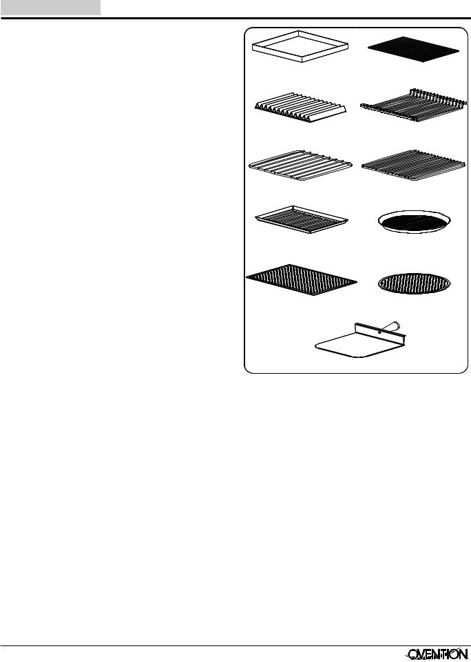
English |
OPTIONS AND ACCESSORIES |
||||
Stacking Kits |
|
|
|
||
Stacking kits are available for stacking one unit on top of |
|
|
|
||
another. The stacking option requires the purchase of an |
|
|
|
||
additional unit along with a stacking kit to secure the top unit to |
Solid Teflon Tray |
Mesh Teflon Tray |
|||
the bottom unit. Installation instructions included in kit. |
|||||
OVNTN-STK-1 ........ |
Stacking kit, model m1718 on m1718 |
|
|
|
|
M1313-STK .............. |
Stacking kit, model m1313 on m1313 |
|
|
|
|
M1313/M1718-STK ..Stacking kit, model m1313 on m1718 |
|
|
|
||
Trays, Racks, and Other Utensils |
Hot Dog Grill |
Offset Rack |
|||
|
|
||||
Several types of trays, racks, and utensils are available for the |
|
|
|
||
matchbox® ovens. |
|
|
|
|
|
M1313-STT ........ |
Solid Teflon Tray, model m1313 |
|
|
|
|
M1718-STT ........ |
Solid Teflon Tray, model m1718 |
Grill Rack |
Pizza Rack |
||
M1313-MTT ........ |
mesh Teflon Tray, model m1313 |
|
|
|
|
M1718-MTT ........ |
mesh Teflon Tray, model m1718 |
|
|
|
|
M1313-HDG........ |
mesh Hot Dog Grill, model m1313 |
Rectangular |
Round |
||
M1718-HDG |
mesh Hot Dog Grill, model m1718 |
||||
Panini Grill Pan |
Panini Grill Pan |
||||
|
|
||||
M1313-OSRK .... |
Offset Rack, model m1313 |
|
|
|
|
M1718-OSRK .... |
Offset Rack, model m1718 |
|
|
|
|
M1313-GRK........ |
Grill Rack, model m1313 |
Pizza Screen |
Round Pizza Screen |
||
M1718-GRK........ |
Grill Rack, model m1718 |
|
|
|
|
M1313-PRK ........ |
Pizza Rack, model m1313 |
|
|
|
|
M1718-PRK ........ |
Pizza Rack, model m1718 |
|
|
|
|
M1313-RCTPG .. |
Rectangular Panini Grill Pan, model m1313 |
|
|
Metal Paddle |
|
M1718-RCTPG .. |
Rectangular Panini Grill Pan, model m1718 |
|
|
|
|
M1313-PG .......... |
Round Panini Grill Pan, model m1313 |
Miscellaneous |
|
||
M1718-PG |
Round Panini Grill Pan, model m1718 |
|
|||
OVNTN-FIL |
Replacement air Filter |
||||
OVNTN-PS11x16 Pizza Screen, 11" x 16" (279 x 406 mm) |
|||||
OVNTN-CLNR Oven Cleaner, case of six bottles |
|||||
OVNTN-PS12 |
Round Pizza Screen, 12" (305 mm) |
||||
NOTE: Use Oven Cleaner to clean cooking grease and residue |
|||||
|
|
||||
OVNTN-PS16 ........ |
Round Pizza Screen, 16" (406 mm) |
safely from the slider system end caps, jet plates, and |
|||
OVNTN-PDL |
metal Paddle |
oven chamber. |
|
||
|
|
|
|||
Form No. OVmm-0116 |
17 |
|
 Loading...