

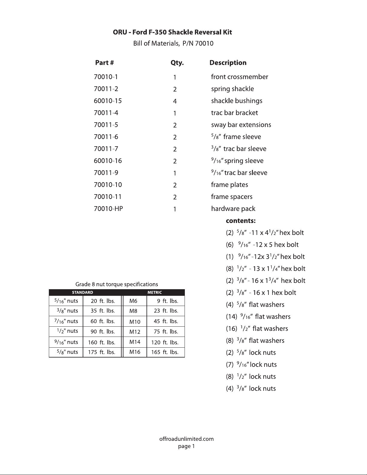

ORU - Ford F-350 Shackle Reversal Kit
INSTALLATION NOTES:
• Inspect the contents of the kit and read the entire instructions before proceeding.
• We recommend this installation be performed by a qualified technician.
• Torque all hardware to factory specifications.
• Use only factory approved fluids.
*** THIS KIT IS FOR 1987-1991 MONOBEAM AXLE TRUCKS ONLY
*** If your truck is equipped with an aftermarket intercooler, you need our special
“drop center” front cross member. Call for details.
1) Remove front bumper and remove front lower trac arm bolt from passenger side of axle housing.
2) Disconnect battery to prevent damage to vehicle’s computer system.
3) Block rear wheels, jack up the front of the truck, and put jack stands under the frame behind
the front leaf springs. Lower the truck so the frame is resting on the jack stands.
4) Remove front wheels.
5) Remove front sway bar links. Cut the links in half, insert halves into provided extension sleeves
and weld together. (Sleeves are 3/4” x 61/2”).
6) * This step is for stock height vehicles. (If you have a lifted suspension, with a dropped pitman
arm, proceed to step #6). Remove drag link from pitman arm. Remove pitman arm. Install new
dropped pitman arm (this item is recommended and must be purchased separately).
7) Support front axle with a jack and remove front spring shackle bolts.
8) Using a floor jack, lower front axle assembly enough to be able to remove shackles.
9) Locate front body mounts below radiator. Support front of body and remove body mount bolts.
Lift body slightly to remove weight from mounts (see photo 1).
10) On both sides, remove 3 rivets that attach body mount to frame and additional 3 that retain
the factory shackle bracket on the inside of the frame. Remove the factory shackle
bracket (see photo 2).
offroadunlimited.com
page 2

ORU - Ford F-350 Shackle Reversal Kit
11) Re-install the body mount brackets with 7/16” x 1” bolts. Re-install body mount bolts and tighten.
12) Remove front shocks and lower axle taking care not to over-extend the brake lines.
13) Place the new “C” channel frame reinforcements inside the frame where the factory shackle
bracket was located. Lightly tap into frame.
14) Place the new front cross member on the frame and align the 5/8” hole on the cross member
with the existing 5/8” hole on the frame. The edge of the new cross member should be
parallel with the front body mount’s edge (see photo 3).
15) Center the “C” channel reinforcement on the new cross member. Using the cross member as
a guide, center punch and drill the 5/8” hole in the “C” channel on both sides. Place the 5/8”
spacer sleeves in the frame and install the 5/8” x 4-1/2” bolts and tighten snug at this
time (see photo 4).
16) Measure 52” from center of rear spring bolt to the center of the new front spring bolt’s
mounting hole. Using the cross member as a guide, center punch and drill the remaining
2 holes on the inside and outside of the frame on both sides. Install 1/2” hardware but do not
tighten at this time (see photo 4 & 5).
17) Tack weld the “C” channel in place on both sides of the vehicle (see photo 5).
18) Remove the cross member and weld the “C” channels to the frame.
19) Re-install the front cross member and hardware. Place the thick “filler washer” in the dimple
on the outside of the frame where the 5/8” bolt goes through. Tighten all hardware.
20) Remove rear bolts from front springs. Install front of spring into the new front hanger.
Use provided 9/16” hardware and install longer shocks (not included, must be purchased
separately) at this time.
21) Cut out paper templates and place them on rear spring hanger using the factory spring
hanger bolt’s hole as a locator. Center punch for new 9/16” hole. Next, cut patterns at the
dotted lines, mark and cut spring hangers* and drill new 9/16” hole (see photo 6).
*CAUTION !! This step is required for the suspension to function properly.
22) Install spring shackle in rear frame hanger with flare hole plate facing forward. Install springs.
Do not tighten spring and shackle bolts fully at this time (see photo 7).
23) Check to be sure the brake lines are not stretched. (You may have to bend the hard lines
towards the frame at the calipers).
offroadunlimited.com
page 3

ORU - Ford F-350 Shackle Reversal Kit
24) Hold bumper bracket up to front of frame and mark lines where new cross member is located.
Cut bumper bracket at marked line (see photo 8). Re-install bumper using remaining hole.
Align bumper. Mark, center punch, and drill second mounting hole. Use factory hardware in
new mounting hole.
25) Install tires, raise front of vehicle and remove jack stands, place vehicle back on ground.
Torque spring and shackle bolts and wheels to specifications.
26) Remove trac arm from lower bracket. (Back of axle housing, passenger side) Loosen
upper track bar bolt (do not remove). Place (2) 3/8” spacers on top of the factory trac arm
bracket at top of the axle housing. Line up spacers with factory holes and leave in position.
Install new bracket on lower end of trac arm, while it is hanging, using provided 9/16” bolt.
Bring bracket and trac arm into position. Using factory hardware, install through track arm
bracket and sleeve. Torque bolts at this time. Drill out remaining holes in front of bracket
and install 3/8” x 7/8” bolts (see photo 9).
27) Install lengthened sway bar links and straighten steering wheel.
photo 1
photo 2 photo 3
offroadunlimited.com
page 4

photo 4
photo 5 photo 6
photo 7
WARRANTY POLICY
ORU (Off Road Unlimited), extends a lifetime warranty on their products to the original purchaser. The warranty covers defects in material and
workmanship. This warranty does not apply to wear items such as brakes, steering components, u-joints, etc., or to products sold by, but not
manufactured by ORU. Application of this warranty is subject to inspection of the product by ORU and at their sole discretion. ORU is not
responsible for shipping charges incurred to submit product for inspection, or its return if the warranty is declined. This warranty does not cover
parts that have been modified, applied outside of the intended application, or subjected to abuse. This warranty applies solely to the ORU product
and does not extend to any incidental damage(s) or incurred cost(s). No other warranties/guarantees are expressed or implied. All warranty claims
must be accompanied by the original receipt, or reasonable facsimile. To apply for warranty consideration, contact the ORU customer service
department at 818-563-1208.
offroadunlimited.com
page 5
photo 8
photo 9

CENTER PUNCH
FOR NEW
9
/16” HOLE
CENTER PUNCH
FOR NEW
9
/16” HOLE
INNER
CUT LINE
EXSITING HOLE
CUT LINE
EXSITING HOLE
OUTER
DRIVER SIDE SPRING HANGER

CENTER PUNCH
FOR NEW
9
/16” HOLE
CENTER PUNCH
FOR NEW
9
/16” HOLE
EXSITING HOLE
OUTER
CUT LINE
CUT LINE
EXSITING HOLE
INNER
PASANGER SIDE SPRING HANGER
 Loading...