

Page 1
Factory Packaged Controls
LED BLINK CODES
LED NAME STATUS1 STATUS2
NORMALOPERATION 0 1
SATFAIL 1 2
EATFAIL 2 2
SPCFAIL 3 2
MECHCOOL FAIL 1 3
MECHHEAT FAIL 2 3
FANPROOF FAIL 3 3
DIRTYFILTER 4 3
WATERFLOW ALARM 6 3
DRAINPAN ALARM 7 3
EMERGENCYSHUTDOWN 5 3
LOWSAT 1 4
HIGHSAT 2 4
CONT.TEMP COOL FAIL 3 4
CONT.TEMP HEAT FAIL 4 4
PUSHBUTTON OVR 1 5
ZONEOVR 2 5
OUTPUTFORCE ACTIVE 0 6
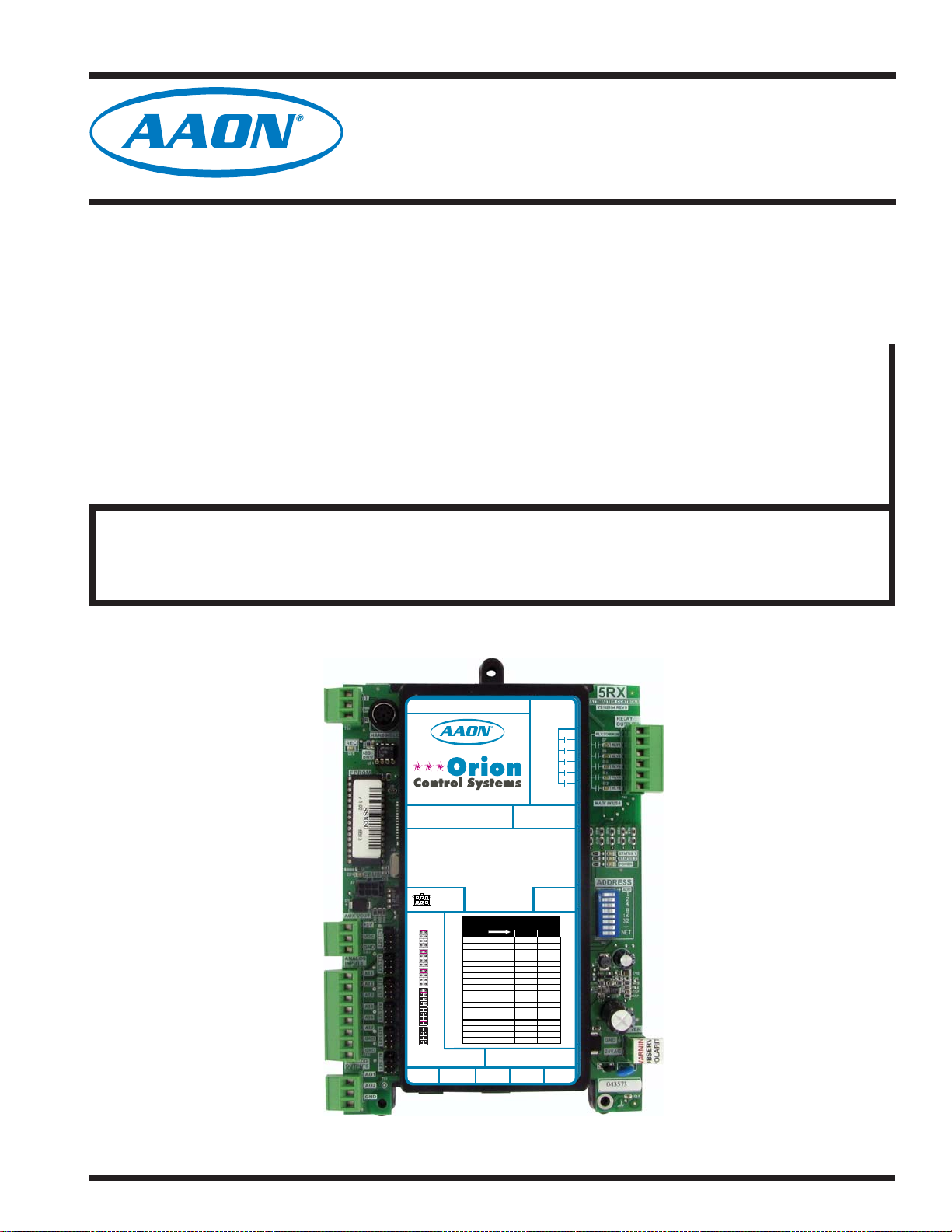
SA E-BUS Controller
Technical Guide
SA E-BUS Controller Code: Y200921
Requires System Manager Code: Y200921SM Version 1.0 and up
Requires Service Tool Code: Y200921HH Version 1.0 and up
RS-485 COMMUNICATION LOOP. WIRE
“R” TO “R”, “T” TO“T” “SHLD” TO “SHLD”
www.aaon.com
www.orioncontrols.com
SA CONTROLLERE-BUS
Orion No.:OE332-23E-VCMX-SA
AI1 = SPC (SPACETEMPERATURE SENSOR)
= SAT(SUPPLY AIR TEMPERATURE SENSOR)
AI2
= EWT (ENTERING WATERTEMPERATURE SENSOR)
AI3
= EAT(ENTERING AIR TEMPERATURE SENSOR)
AI4
AI5
= NOT USED
AI7
= SPACETEMPERATURE SENSOR SLIDE ADJUST
OR VOLTAGE RESETSOURCE
A01
= WATER SIDE ECONOMIZER VALVE 1A &1B (2-10 VDC)
A02
= SUPPLYFAN VFD (0-10 VDC OUTPUT)
E-BUS
CONNECTOR
ANALOG INPUT
JUMPER
SETTINGS
THERM
4-20mA
AI1
0-10V
0-5V
THERM
4-20mA
AI2
0-10V
0-5V
THERM
4-20mA
AI3
0-10V
0-5V
THERM
4-20mA
AI4
0-10V
0-5V
THERM
4-20mA
AI5
0-10V
0-5V
THERM
4-20mA
AI7
0-10V
0-5V
ANALOG INPUT JUMPER SETTINGS
MUST BE SETAS SHOWN FOR
PROPER OPERATION
WattMaster Label
STATIC
#LB102060-01-A
PRESSURE
Rev.: 1A
EXPANSION
WARNING!POLARITY MUST BE OBSERVED
OR THE CONTROLLER WILL BE DAMAGED
2
IC
RELAYCONTACT
RATING IS 1AMP
MAX @ 24 VAC
RELAY
COMMON
FAN
RELAY2
RELAY3
RELAY4
RELAY5
AAON No.:
V07160
24 VAC POWER ONLY
2
I C DIGITAL
SENSOR
Page 2
Table of Contents
OVERVIEW ....................................................................................................................................... 4
Part Number Cross Reference ..................................................................................................................................................4
Features and Applications ........................................................................................................................................................5
SA E-BUS Controller Dimensions ............................................................................................................................................6
SA Expansion Module Dimensions ..........................................................................................................................................7
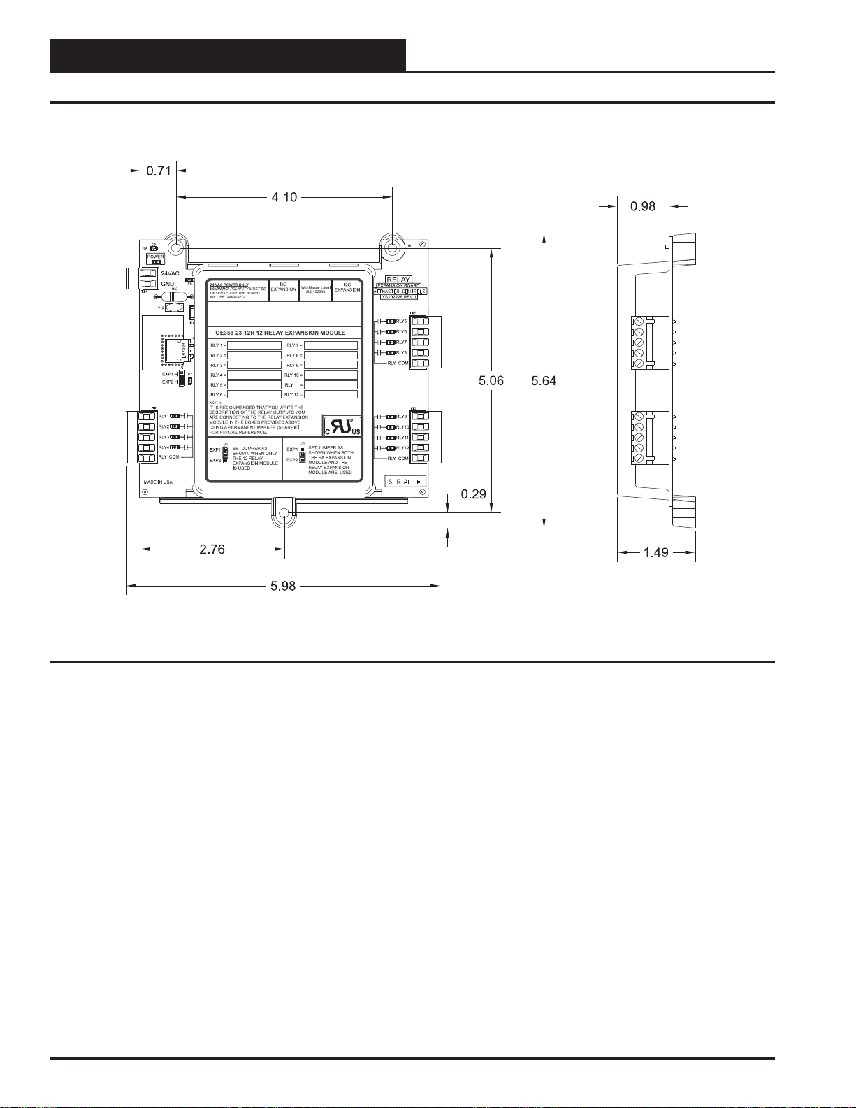
12-Relay Expansion Module Dimensions ................................................................................................................................8
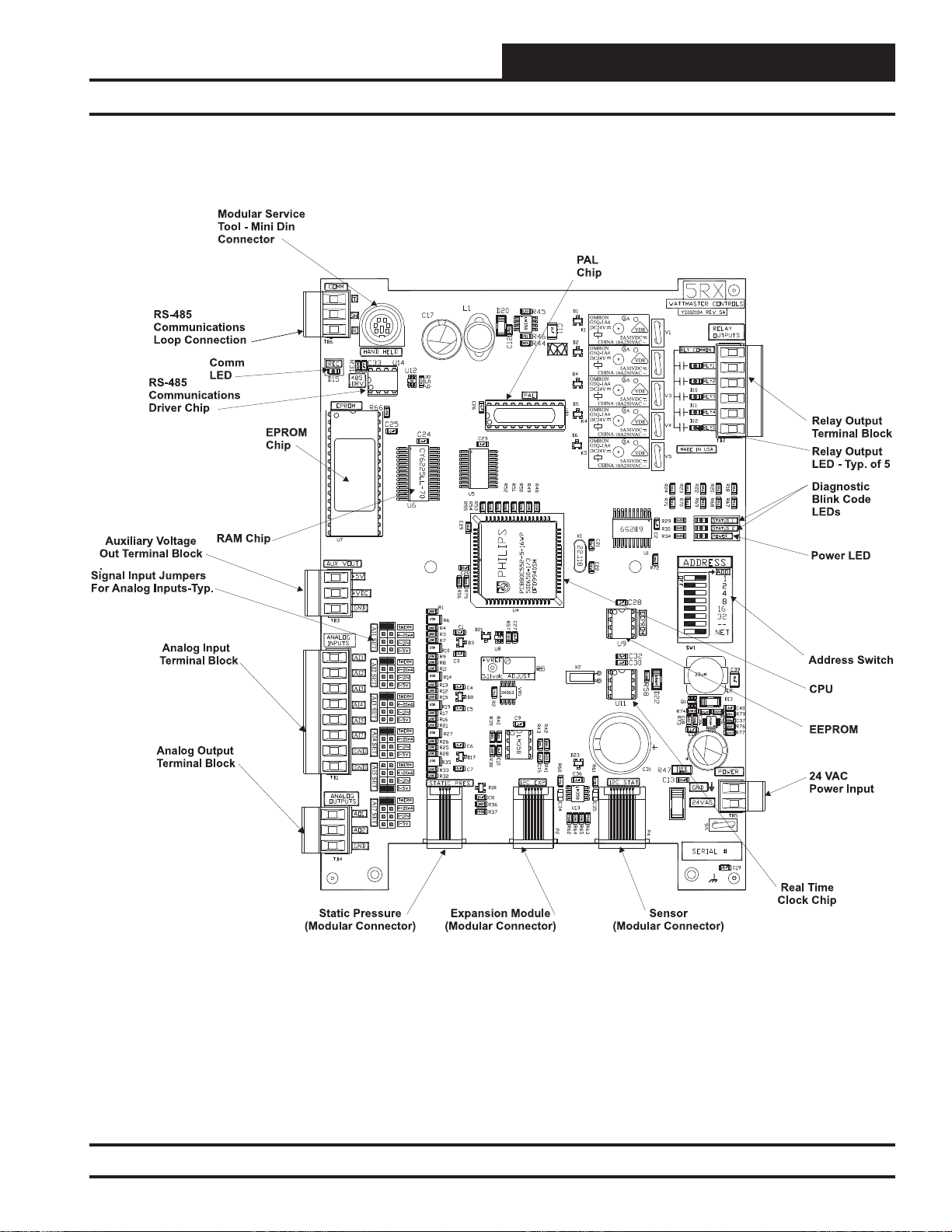
SA E-BUS Controller Component Locations ...........................................................................................................................9
INSTALLATION AND WIRING ........................................................................................................10
Important Wiring Considerations ...........................................................................................................................................10
SA E-BUS Controller Wiring ...................................................................................................................................................11
Digital Room Sensor ..........................................................................................................................................................12
Space Temperature Sensor ...............................................................................................................................................13
Remote SAT Reset Signal .................................................................................................................................................13
Supply Air Temperature Sensor ................................................................................................. ........................................14
Entering Water Temperature Sensor .................................................................................................................................15
Entering Air Temperature Sensor .......................................................................................................................................16
Water Side Economizer Valve ...........................................................................................................................................17
Water Side Economizer Bypass Valve ..............................................................................................................................17
Supply Fan VFD Signal or Zoning Bypass Damper Actuator Signal .................................................................................18
SA Expansion Module Input Wiring ........................................................................................................................................20
SA Expansion Module Output Wiring .....................................................................................................................................21
Suction Pressure Transducer ............................................................................................................................................22
SA Expansion Module Binary Inputs ................................................................................................................................23
Entering Air Humidity Sensor .............................................................................................................................................24
Indoor Wall-Mounted Humidity Sensor ..............................................................................................................................25
Modulating Heating Device ................................................................................................................................................26
Modulating Cooling Device ................................................................................................................................................27
12-Relay Expansion Module .............................................................................................................................................30
ADDITIONAL APPLICATIONS ........................................................................................................32
SA E-BUS Controller to Module Wiring .................................................................................................................................32
Two Condenser Head Pressure Module ............................................................................................................................34
Water Source Heat Pump Modules ...................................................................................................................................35
START-UP AND COMMISSIONING ................................................................................................. 36
Addressing & Powering Up .....................................................................................................................................................36
Before Applying Power ......................................................................................................................................................36
Controller Addressing ........................................................................................................................................................36
Power Wiring ....................................................................................................................................................................36
Initialization ........................................................................................................................................................................37
Operating Summary ..........................................................................................................................................................37
Programming the Controller ...................................................................................................................................................37
www.aaon.com
WattMaster Controls Inc.
8500 NW River Park Drive · Parkville , MO 64152
Toll Free Phone: 866-918-1100
PH: (816) 505-1100 · FAX: (816) 505-1101 · E-mail: mail@wattmaster.com
Visit our web site at www.orioncontrols.com
WattMaster Form : AA-SA-EBUS-TGD-01D
Copyright March 2015 WattMaster Controls, Inc.
AAON Part Number: V10910
®
AAON
is a registered trademark of AAON, Inc., Tulsa, OK.
Copeland Digital Scroll™ is a registered trademark of Copeland Corporation,
Sidney, OH
EBTRON® is a registered trademark of Ebtron, Inc., Loris, SC.
Neither WattMaster Controls, Inc. nor AAON
assumes any responsibility for errors or omissions in this document.
This document is subject to change without notice.
®
Page 3

Table of Contents
INPUTS AND OUTPUTS ................................................................................................................ 38
SA E-BUS Controller Inputs and Outputs ..............................................................................................................................38
SA Expansion Module Inputs and Outputs ............................................................................................................................39
SEQUENCE OF OPERATION ..........................................................................................................41
Operation Modes ......................................................................................................................................................................41
Occupied/Unoccupied Mode of Operation .........................................................................................................................41
HVAC Modes of Operation ................................................................................................................................................41
Vent Mode Operation .........................................................................................................................................................41
Cooling Mode Operation ....................................................................................................................................................41
Stage Control Window .......................................................................................................................................................42
Modulating Cooling ............................................................................................................................................................42
DX Cooling .......................................................................................................................................................................42
Air Cooled Condenser Fan Operation ...............................................................................................................................43
Water Side Economizer Operation (Valves 1 & 2) .............................................................................................................43
Water Cooled Condenser (Valve 3) ...................................................................................................................................43
Chilled Water Cooling ........................................................................................................................................................44
External Cooling ................................................................................................................................................................44
Dehumidifi cation Mode ......................................................................................................................................................44
Coil Temperature Reset .....................................................................................................................................................44
Reheat Control ..................................................................................................................................................................45
Coil Temperature Offset .....................................................................................................................................................45
Heating Mode ...................................................................................................................................................................46
Stage Control Window .......................................................................................................................................................46
Modulating Hot Water or Steam Heating ...........................................................................................................................46
External Heat .....................................................................................................................................................................46
Air to Air Heat Pump Operation .........................................................................................................................................46
Water Source Heat Pump Operation .................................................................................................................................47
Morning Warm-Up Mode ...................................................................................................................................................47
Off Mode ............................................................................................................................................................................47
Supply Air Temperature Setpoint Reset .............................................................................................................................47
Supply Fan Control ............................................................................................................................................................48
Duct Static Pressure Control .............................................................................................................................................48
Pre-Heater Operation ........................................................................................................................................................49
Entering Air Lockouts ......................................................................................................... ................................................49
Supply Air Cutoffs ..............................................................................................................................................................49
SA E-BUS Controller Alarms .............................................................................................................................................50
VAV/Zone Controller Alarms ..............................................................................................................................................51
Scheduling .........................................................................................................................................................................52
Internal Trend Logging .......................................................................................................................................................52
Force Modes or Overrides .................................................................................................................................................53
VAV Terminal Unit Controller Compatibility ........................................................................................................................53
VAV/Zone System & Zoning System .................................................................................................................................53
TROUBLESHOOTING ..................................................................................................................... 54
LED Diagnostics .......................................................................................................................................................................54
Diagnostic LED Operation .......................................................................................................................................................55
APPENDIX ..................................................................................................................................... 56
System Confi gurations ............................................................................................................................................................56
Stand-Alone System Layout ..............................................................................................................................................57
Interconnected System Layout ..........................................................................................................................................58
Networked System Layout .................................................................................................................................................59
Temperature Sensor Testing ...................................................................................................................................................60
OE265 Series RH Sensor Testing .....................................................................................................................................61
OE271 Pressure Sensor Testing .......................................................................................................................................62
OE275-01 Suction Pressure Transducer Testing for R410A Refrigerant ...........................................................................63
INDEX ............................................................................................................................................ 64
SA E-BUS Controller Technical Guide 3
Page 4

Overview
Part Number Cross Reference
PART DESCRIPTION
SA E-BUS Controller OE332-23E-VCMX-SA-A V07160
SA Expansion Module OE333-23-SA-A R96180
12-Relay Expansion Module OE358-23-12R R69180
Two Condenser Head Pressure Module OE370-23-HP2C R90230
Water Source Heat Pump Protection Module - 410A OE334-23-WPM-A R88350
Water Source Heat Pump Protection Module - 410A - 20% Glycol OE334-23-WPM-A20 R99750
Water Source Heat Pump Protection Module - 410A - 40% Glycol OE334-23-WPM-A40 R99760
Bypass & Slave Interface Card PL101824 N/A
Bypass Damper Actuator OE281-04 N/A
CommLink 5 Communications Interface OE361-13 V32950
Digital Room Sensor - Temp & Humidity OE217-01 R83870
Digital Room Sensor - Temp. Only OE217-00 R83860
Duct Static Pressure Sensor OE271 P87100
Duct Temperature Sensor - 12" Probe OE231 R44940 / P87140
Duct Temperature Sensor - 6" Probe OE230 R36340
IP Module Kit OE415-02 R66770
MiniLink Polling Device OE364-22 N/A
Modular Service Tool SD - Operator Interface OE391-12 V28140
Modular System Manager SD - Operator Interface OE392-12 V36570
Entering Air RH Sensor - 3% - 0-5 VDC Output OE265-14 R34700
Entering Air Temperature Sensor OE250 R34650
Room Mounted RH Sensor - 3% - 0-5 VDC Output OE265-11 R34690
Standard Room Sensor - Plain OE210 R31480
Standard Room Sensor - w/ Override OE211 P87040
Standard Room Sensor - w/ Override & Slide Adjust OE213 P94320
Standard Room Sensor - w/ Slide Adjust OE212 P94100
Static Pressure Pickup Tube OE290 S18780
Suction Pressure Transducer OE275-01 R28390
USB-Link 2 Kit OE366 R71870
ORION
PART NO:
AAON TULSA
PART NO:
4
SA E-BUS Controller Technical Guide
Page 5

Overview
Features and Applications
Features
The Series A Controller (OE332-23E-VCMX-SA)—SA E-BUS Controller—is designed with 6 analog inputs, 2 analog outputs, and 5 relay
outputs. Most common HVAC unit control applications can be confi gured using only the SA E-BUS Controller; however, if needed, the
SA E-BUS Controller’s input and output capabilities can be expanded
with the SA Expansion Module ( OE333-23-SA) or 12-Relay Expansion
Module (OE358-23-12R) by means of a modular cable. The SA Expansion Module provides an additional 4 analog inputs, 5 analog outputs,
8 binary inputs, and 4 confi gurable relays. The 12-Relay Expansion
Module provides an additional 12 confi gurable relays.
The SA E-BUS Controller can also use the Two Condenser Head Pressure Module ( OE370-23-HP2C) for those applications requiring Head
Pressure Control. The SA E-BUS Controller can also use the WSHP
Module (OE334-23-WPM-A) for W ater Source Heat Pump applications.
Each SA E-BUS Controller can be confi gured for control of VAV Units
(with or without VAV/Zone Controllers), Constant Volume Units, and
Make-Up Air Units. Features include the following:
• Modulating Cooling Output ( Copeland Digital
Scroll™ Compressor or Chilled Water Valve Control)
• Modulating Heating Output ( Hot Water Valve,
Steam Valve, SCR Electric Heat Control)
• Full Integration with the AAON
Hot Gas Reheat Valve Controller
®
MHGRV Modulating
• Confi gurable for Air to Air and Water Source Heat Pump
Applications
• Advanced Dehumidifi cation Capabilities
• Adaptive Supply Air Reset
• Selectable Control Sensor
• Fan Proving Interlock
• Dirty Filter Alarm
• Emergency Shutdown Input (Smoke Detector/Firestat or
other Shutdown Conditions)
• Water Side Economizer Option
• Remote Occupied Capabilities
• 7-Day, 2-Event-per-Day Scheduling
• 14 Holiday Event Scheduling
• Optimal Start Scheduling
• Trend Logging Capability
• Static Pressure Control for Filter Loading Applications
• Head Pressure Control (with optional Two Condenser Head
Pressure Module)
• Additional Water Safeties (with optional Water
Source Heat Pump Module)
Applications
Variable Air Volume Unit
The SA E-BUS Controller can be confi gured to control a VFD Supply
Fan for Duct Static Pressure control. If the unit is not equipped with a
VFD, but Duct Static Pressure control is needed, a modulating Zoning
Bypass Damper can be controlled by the SA E-BUS Controller.
VAV units are typically designed for occupied Cooling with Morning
W arm-up Heating. This option is available with the SA E-BUS Controller. The SA E-BUS Controller can also be used for a Zoning System that
needs Duct Static Pressure control and Occupied Cooling and Heating.
The SA E-BUS Controller also has the ability to be confi gured for Duct
Static Pressure Control by controlling the Supply Fan VFD for the purpose of maintaining proper Duct Static Pressure in response to varying
fi lter loading conditions.
The SA E-BUS Controller allows Dehumidifi cation Priority on a VAV
unit. This could be useful on a building with a very low internal sensible
load, but which has a high internal and/or external latent load. During
VAV Dehumidifi cation, the SA E-BUS Controller activates Cooling
based on the Evaporator Coil Temperature and activates
lating Hot Gas Reheat to warm the Supply Air Temperature to the Active
Supply Air Temperature Setpoint.
Constant Air Volume Unit
The SA E-BUS Controller can be confi gured to activate a Constant
Volume Supply Fan. In most cases, this is a very basic unit with Space
Temperature control.
Make-Up Air Unit
The SA E-BUS Controller can be confi gured for 100% Outdoor Air
control for Make-Up Air. All HVAC Modes are determined from the
Outdoor Air Sensors. The Outdoor Air Volume must always be at least
50% or higher to be confi gured for Outdoor Air control.
Single or Dual Cabinet Unit
The SA E-BUS Controller can control an SA Series Single Cabinet Unit
or an SA Series Dual Cabinet Unit. Wiring for Dual Cabinet Units is
shown and noted on applicable Single Cabinet Unit diagrams.
AAON® Modu-
SA E-BUS Controller Technical Guide
5
Page 6
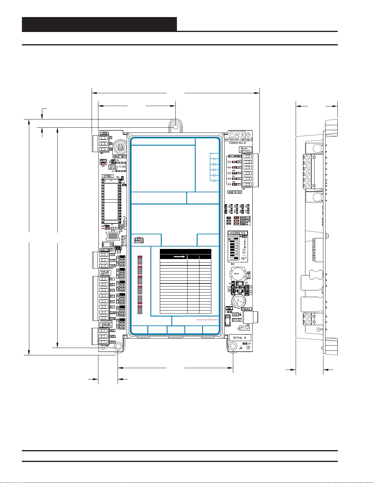
Overview
SA E-BUS Controller Dimensions
5.985.98
8.388.38
0.290.29
7.837.83
2.752.75
RS-485 COMMUNICATION LOOP. WIRE
“R” TO “R”, “T” TO “T” “SHLD” TO “SHLD”
RS-485 COMMUNICATION LOOP. WIRE
RS-485 COMMUNICATION LOOP. WIRE
“R” TO “R”, “T” TO “T” “SHLD” TO“SHLD”
“R” TO “R”, “T” TO “T” “SHLD” TO“SHLD”
www.aaon.com
www.orioncontrols.com
www.orioncontrols.com
SA CONTROLLERE-BUS
SA CONTROLLERE-BUS
Orion No.:OE332-23E-VCMX-SA
OE332-23-VCMX-A VCM-X CONTROLLER
Orion No.:OE332-23E-VCMX-SA
AI1 = SPC (SPACE TEMPERATURE SENSOR)
AI1 = SPC (SPACE TEMPERATURE SENSOR)
AI1 = SPC (SPACE TEMPERATURE SENSOR)
AI2
= SAT (SUPPLYAIR TEMPERATURE SENSOR)
= SAT (SUPPLYAIR TEMPERATURE SENSOR)
AI2
= SAT (SUPPLYAIR TEMPERATURE SENSOR)
AI2
AI3
= EWT (ENTERING WATERTEMPERATURE SENSOR)
= EWT (ENTERING WATERTEMPERATURE SENSOR)
AI3
= RAT (RETURNAIR TEMPERATURE SENSOR)
AI3
AI4
= EAT (ENTERINGAIR TEMPERATURE SENSOR)
= EAT (ENTERINGAIR TEMPERATURE SENSOR)
AI4
= OAT (OUTDOORAIR TEMPERATURE SENSOR)
AI4
AI5
= NOT USED
= NOT USED
AI5
AI5
= SUCTION PRESSURE SENSOR
AI7
= SPACE TEMPERATURE SENSOR SLIDEADJUST
= SPACE TEMPERATURE SENSOR SLIDEADJUST
AI7
AI7
= SPACE TEMPERATURE SENSOR SLIDEADJUST
OR VOLTAGE RESETSOURCE
OR VOLTAGE RESETSOURCE
OR VOLTAGE RESETSOURCE
A01
= WATER SIDE ECONOMIZER VALVE 1A &1B (2-10 VDC)
= WATER SIDE ECONOMIZER VALVE 1A &1B (2-10 VDC)
A01
A01
= ECONOMIZER (2-10 VDC OUTPUT)
A02
= SUPPLY FAN VFD (0-10 VDC OUTPUT)
= SUPPLY FAN VFD (0-10 VDC OUTPUT)
A02
A02
= SUPPLY FAN VFD (0-10 VDC OUTPUT)
E-BUS
E-BUS
CONNECTOR
CONNECTOR
ANALOG INPUT
ANALOG INPUT
ANALOG INPUT
JUMPER
JUMPER
JUMPER
SETTINGS
SETTINGS
SETTINGS
THERM
THERM
THERM
4-20mA
4-20mA
4-20mA
AI1
AI1
AI1
0-10V
0-10V
0-10V
0-5V
0-5V
0-5V
THERM
THERM
THERM
4-20mA
4-20mA
4-20mA
AI2
AI2
AI2
0-10V
0-10V
0-10V
0-5V
0-5V
0-5V
THERM
THERM
THERM
4-20mA
4-20mA
AI3
4-20mA
AI3
0-10V
0-10V
AI3
0-10V
0-5V
0-5V
0-5V
THERM
THERM
THERM
4-20mA
4-20mA
AI4
AI4
4-20mA
0-10V
0-10V
AI4
0-10V
0-5V
0-5V
0-5V
THERM
THERM
THERM
4-20mA
4-20mA
AI5
AI5
4-20mA
0-10V
0-10V
AI5
0-10V
0-5V
0-5V
0-5V
THERM
THERM
THERM
4-20mA
4-20mA
AI7
AI7
4-20mA
0-10V
0-10V
AI7
0-10V
0-5V
0-5V
0-5V
ANALOG INPUT JUMPER SETTINGS
ANALOG INPUT JUMPER SETTINGS
MUST BE SETAS SHOWN FOR
MUST BE SETAS SHOWN FOR
ANALOG INPUT JUMPER SETTINGS
PROPER OPERATION
PROPER OPERATION
MUST BE SETAS SHOWN FOR
PROPER OPERATION
PRESSURE
STATIC
STATIC
STATIC
PRESSURE
PRESSURE
WattMaster Label
WattMaster Label
#LB102060-01-A
WattMaster Label
#LB102033-01
Rev.: 1A
#LB102060-01-A
Rev.: 1A
LED BLINK CODES
LED BLINK CODES
LED NAME STATUS1 STATUS2
LED NAME STATUS1 STATUS2
NORMAL OPERATION 0 1
NORMAL OPERATION 0 1
SAT FAIL 1 2
SAT FAIL 1 2
EAT FAIL 2 2
EAT FAIL 2 2
SPC FAIL 3 2
SPC FAIL 3 2
MECH COOL FAIL 1 3
MECH COOL FAIL 1 3
MECH HEAT FAIL 2 3
MECH HEAT FAIL 2 3
FAN PROOF FAIL 3 3
FAN PROOF FAIL 3 3
DIRTY FILTER 4 3
DIRTY FILTER 4 3
WATER FLOW ALARM 6 3
WATER FLOW ALARM 6 3
DRAIN PAN ALARM 7 3
DRAIN PAN ALARM 7 3
EMERGENCY SHUTDOWN 5 3
EMERGENCY SHUTDOWN 5 3
LOW SAT 1 4
LOW SAT 1 4
HIGH SAT 2 4
HIGH SAT 2 4
CONT. TEMP COOL FAIL 3 4
CONT. TEMP COOL FAIL 3 4
CONT. TEMP HEAT FAIL 4 4
CONT. TEMP HEAT FAIL 4 4
PUSH BUTTON OVR 1 5
PUSH BUTTON OVR 1 5
ZONE OVR 2 5
ZONE OVR 2 5
OUTPUT FORCE ACTIVE 0 6
OUTPUT FORCE ACTIVE 0 6
WARNING! POLARITY MUST BE OBSERVED
WARNING!POLARITY MUST BE OBSERVED
OR THE CONTROLLER WILL BE DAMAGED
OR THE CONTROLLER WILL BE DAMAGED
WARNING! POLARITY MUST BE OBSERVED
OR THE CONTROLLER WILL BE DAMAGED
2
2
IC
IC
2
IC
EXPANSION
EXPANSION
EXPANSION
AAON No.:
AAON No.:
24 VAC POWER ONLY
RELAY CONTACT
RATING IS 1AMP
RELAY CONTACT
RELAY CONTACT
MAX @ 24 VAC
RATING IS 1AMP
RATING IS 1AMP
MAX @ 24 VAC
MAX @ 24 VAC
RELAY
RELAY
COMMON
RELAY
COMMON
COMMON
FAN
FAN
FAN
RELAY 2
RELAY 2
RELAY 2
RELAY 3
RELAY 3
RELAY 3
RELAY 4
RELAY 4
RELAY 4
RELAY 5
RELAY 5
RELAY 5
V07160
V07160
24 VAC POWER ONLY
24 VAC POWER ONLY
2
2
IC DIGITAL
IC DIGITAL
2
IC DIGITAL
SENSOR
SENSOR
SENSOR
OBSERVE
POLARITY
1.49
WARNING
4.104.10
0.700.70
Figure 1: OE332-23E-SA E-BUS Controller – SA E-BUS Controller Dimensions
6
SA E-BUS Controller Technical Guide
0.980.98
Page 7
8.38
7.83
0.29
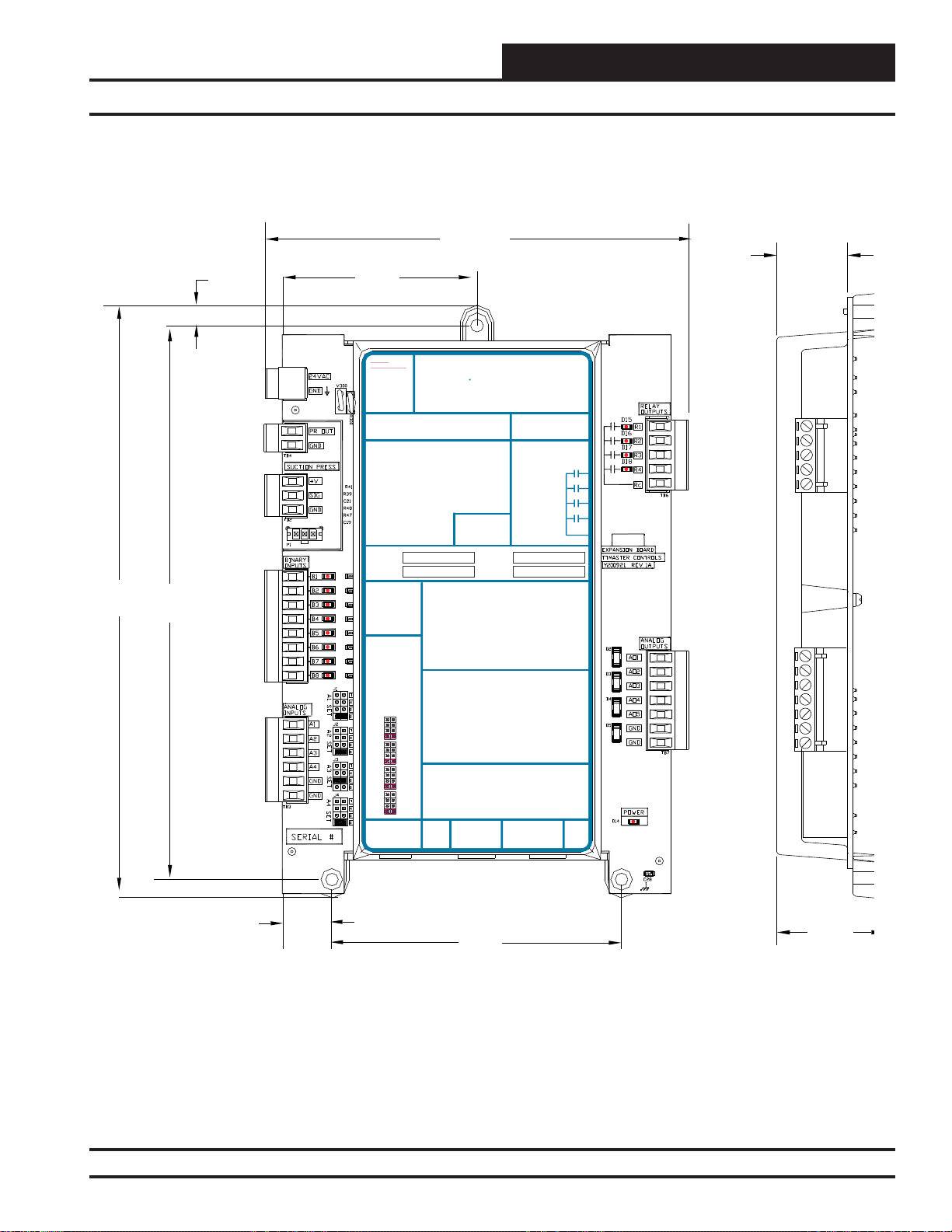
Overview
SA Expansion Module Dimensions
5.98
0.98
2.75
24 VAC
24 VAC POWER ONLY
POWER ONLY
WARNING! POLARITY MUST BE
WARNING!
OBSERVED OR THE BOARD
POLARITY
WILL BE DAMAGED
MUST BE
OBSERVED OR
POLARITY
WARNING
OBSERVE
THE BOARD
WILL BE
DAMAGED
SA Expansion Module
Orion No.:OE333-23-SA
OE333-23-EM-A VCM-X EXPANSION MODULE
PR OUT
TO VCM-X INPUT
GND
TERMINALS AI5 & GND
SUCTION PRESSURE
+V
TRANSDUCER CONNECTION
SIG
FOR HVAC UNITS WITHOUT
GND
DIGITALCOMPRESSOR
RELAY 1 = RELAY 3 =
RELAY 2 = RELAY 4 =
RELAY 1 = RELAY 3 =
IT IS SUGGESTED
THATYOU WRITE THE
DESCRIPTION OF
RELAY 2 = RELAY 4 =
THE RELAYOUTPUTS
YOUARE USING IN
IT IS SUGGESTED
THE BOXES
THATYOU WRITE THE
PROVIDEDABOVE
DESCRIPTION OF
WITHA PERMANENT
THE RELAYOUTPUTS
MARKER (SHARPIE®)
YOUARE USING IN
THE BOXES
PROVIDEDABOVE
WITHA PERMANENT
ANALOG INPUT
MARKER (SHARPIE®)
JUMPER SETTINGS
MUST BE SETAS
SHOWN FOR
PROPER
ANALOG INPUT
OPERATION
JUMPER SETTINGS
MUST BE SETAS
SHOWN FOR
PROPER
ANALOG INPUT
OPERATION
JUMPER
SETTINGS
THERM
ANALOG INPUT
4-20mA
JUMPER
AI1
0-10V
SETTINGS
0-5V
THERM
THERM
4-20mA
4-20mA
AI1
AI2
0-10V
0-10V
0-5V
0-5V
THERM
THERM
4-20mA
AI2
4-20mA
0-10V
AI3
0-10V
0-5V
0-5V
THERM
THERM
4-20mA
AI3
4-20mA
0-10V
AI4
0-10V
0-5V
0-5V
THERM
4-20mA
AI4
0-10V
I2C
0-5V
EXPANSION
I2C
WattMaster Label
EXPANSION
www.orioncontrols.com
BI1 = WATER PROOF OF FLOW -A - N.O. INPUT
BI2
= WATER PROOF OF FLOW - B - N.O. INPUT
BI3
= AIR PROOF OF FLOW - N.O. INPUT
BI4
= REMOTE FORCED OCCUPIED - N.O. INPUT
BI1 = HOOD ON - N.O. INPUT
BI5
= EMERGENCY SHUTDOWN - N.C. INPUT
= DIRTY FILTER - N.O. INPUT
BI2
BI6
= DRAIN PAN OVERFLOW -A - N.O. INPUT
= PROOF OF FLOW - N.O. INPUT
BI3
BI7
= DRAIN PAN OVERFLOW - B - N.O. INPUT
= REMOTE FORCED OCCUPIED - N.O. INPUT
BI4
BI8
= DIRTY FILTER - N.O. INPUT
= REMOTE FORCED HEATING - N.O. INPUT
BI5
= REMOTE FORCED COOLING - N.O. INPUT
BI6
NOTE:
= SMOKE DETECTOR - N.C. INPUT
BI7
ALL BINARY INPUTS MUST BE 24 VAC ONLY.
= REMOTE DEHUMIDIFICATION - N.O. INPUT
BI8
NOTE:
AO1 = MODULATING HEATING SIGNAL
ALL BINARY INPUTS MUST BE 24 VAC ONLY.
(0-10 VDC OR 2-10 VDC)
= MODULATING COOLING STAGE 1 SIGNAL
AO2
(0-10 VDC, 2-10 VDC OR 1.5-5 VDC)
AO1 = BUILDING PRESSURE CONTROL VFD OR
= MODULATING COOLING STAGE 2 SIGNAL
AO3
DAMPER ACTUATOR (0-10 OR 2-10 VDC)
(DIGITALCOMPRESSOR ONLY 1.5-5 VDC)
AO2
= MODULATING HEATING SIGNAL
= WSE BYPASS 2ASIGNAL
AO4
(0-10 VDC OR 2-10 VDC)
(0-10 VDC)
AO3
= MODULATING COOLING/DIGITALSCROLL
= WSE BYPASS 2B SIGNAL
AO5
SIGNAL (0-10 VDC, 2-10 VDC OR 1.5-5 VDC)
(0-10 VDC)
AO4
= RETURN AIR DAMPERACTUATOR
= GROUND FOR ANALOG OUTPUTS
GND
(0-10 VDC)
= GROUND FOR ANALOG OUTPUTS
GND
AO5
= RETURN AIR BYPASS DAMPERACTUATOR
(0-10 VDC)
GND
= GROUND FOR ANALOG OUTPUTS
AI1 = ENTERING AIR RH SENSOR (0-5 VDC)
GND
= GROUND FOR ANALOG OUTPUTS
AI2
= INDOOR AIR RH SENSOR (0-5 VDC)
AI3
= SUCTION PRESSURE A(0-5 VDC)
AI4
= SUCTION PRESSURE B (0-5 VDC)
AI1 = OUTDOOR AIR RH SENSOR (0-5 VDC)
GND
= GROUND FOR ANALOG INPUTS
= INDOOR AIR RH SENSOR (0-5 VDC)
AI2
GND
= GROUND FOR ANALOG INPUTS
= CO2 (0-10 VDC)
AI3
= BUILDING STATIC PRESSURE (0-5 VDC)
AI4
= GROUND FOR ANALOG INPUTS
GND
= GROUND FOR ANALOG INPUTS
GND
I2C
EXPANSION
#LB102034-01
AAON No.:
WattMaster Label
#LB102061-A
Rev.: 1C
EXPANSION
R96180
RELAY CONTACT
RATING IS 1AMP
MAX @ 24 VAC
RELAY CONTACT
RATING IS 1AMP
RELAY 1
MAX @ 24 VAC
RELAY 2
RELAY 1
RELAY 3
RELAY 2
RELAY 4
RELAY 3
RELAY
RELAY 4
COMMON
RELAY
COMMON
I2C
SA
0.70
4.10
Figure 2: OE333-23-SA – SA Expansion Module Dimensions
SA E-BUS Controller Technical Guide
1.49
7
Page 8
Overview
12-Relay Expansion Module Dimensions
Figure 3: OE358-23-12R – 12-Relay Expansion Module Dimensions
8
SA E-BUS Controller Technical Guide
Page 9
Overview
SA E-BUS Controller Component Locations
Figure 4: OE332-23E-SA – SA E-BUS Controller Component Locations
SA E-BUS Controller Technical Guide
9
Page 10
Installation & Wiring
Important Wiring Considerations
Zone
Zone
General
Correct wiring of the SA E-BUS Controller is the most important
factor in the overall success of the controller installation process. In
general, most SA E-BUS Controllers are factory installed and wired at
the AAON
®
factory.
Controller Mounting
When the controller is to be fi eld mounted, it is important to mount the
controller in a location that is free from extreme high or low temperatures,
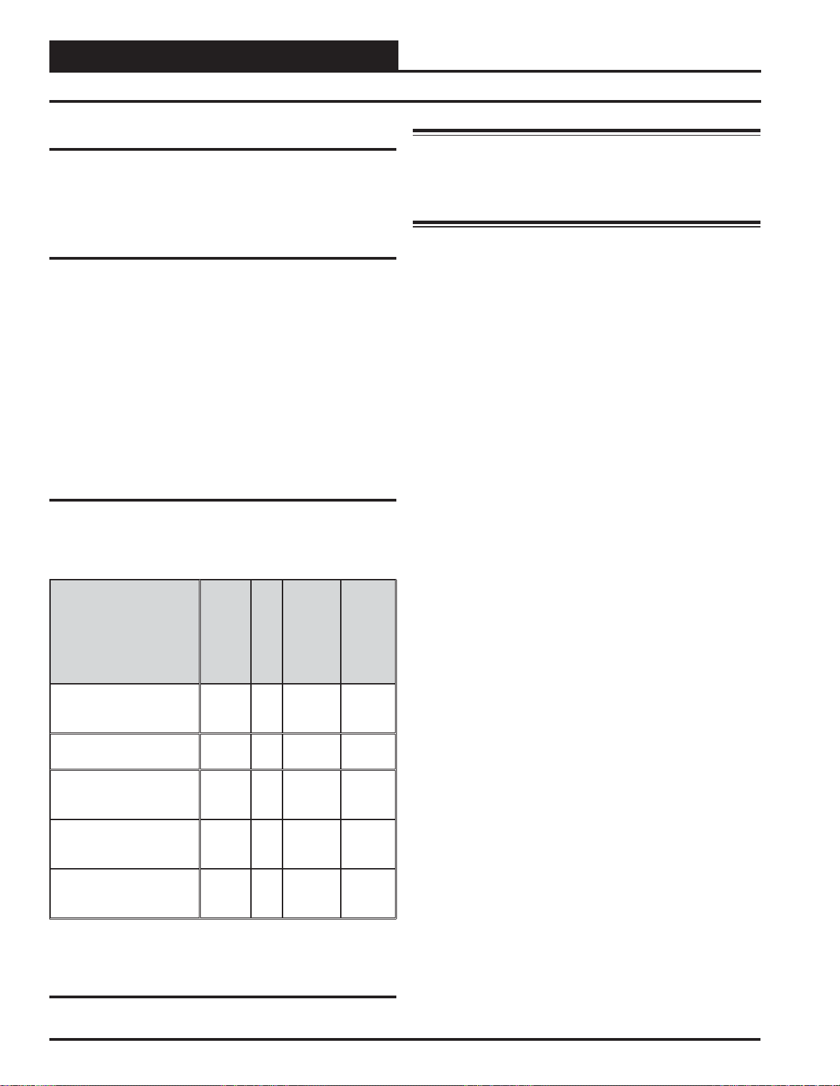
moisture, dust, and dirt. See Table 1 for a list of the required operating
conditions for the SA E-BUS Controller and associated modules.
The SA E-BUS Controller is housed in a plastic enclosure. It is designed
to be mounted by using the 3 mounting holes in the enclosure base. The
SA E-BUS Controller needs to be installed in an environment which can
maintain a temperature range between -30°F and 150°F not to exceed
90% RH levels (non-condensing). It is important to mount the controller
in a location that is free from extreme high or low temperatures, moisture,
dust, and dirt. Be careful not to damage the electronic components when
mounting the controller.
Considerations
The SA E-BUS Controller and associated modules must be connected
to a 24 VAC power source of the proper size for the calculated VA load
requirements. All transformer sizing should be based on the VA rating
listed in Table 1.
Device
Control
OE332-23E-SA E-BUS
Controller
SA E-BUS Controller
OE333-23-SA
SA Expansion Module 24VAC
OE358-23-12R
12-Relay Expansion
Module
OE370-23-HP2C
Two Condenser Head
Pressure Module
OE334-23-WPM-A
Water Source Heat Pump
Module
24VAC 8
24VAC 15
24VAC 5
24VAC 8
Voltage
VA Load
-30°F to
150°F
-30°F to
10
150°F 90% RH
-30°F to
150°F
-30°F to
150°F
-30°F to
150°F
Temperature
(Non-
Humidity
Condensing)
90% RH
90% RH
90% RH
90% RH
Warning: When using a single transformer to power more
than one controller or expansion module, the correct polarity must
always be maintained between the boards. Failure to observe correct
polarity will result in damage to the SA E-BUS Controller and
associated modules.
Please carefully read and apply the following information when wiring
the SA E-BUS Controller or its associated modules. See Figure 5 on
page 11 for the SA E-BUS Controller wiring diagram. See Figures 16
and 17 on pages 20 and 21 for SA Expansion Module wiring. And see
Figure 25 on page 31 for 12-Relay Expansion Module wiring.
1. All wiring is to be in accordance with local and national
electrical codes and specifi cations.
2. Minimum wire size for 24 VAC wiring should be 18-gauge.
3. Minimum wire size for all sensors should be 24-gauge.
Some sensors require 2-conductor wire and some require
3-or 4-conductor wire.
4. Be sure that all wiring connections are properly inserted
and tightened into the terminal blocks. Do not allow wire
strands to stick out and touch adjoining terminals which
could potentially cause a short circuit.
5. When communication wiring is to be used to interconnect
SA E-BUS Controllers together or to connect to other
communication devices, all wiring must be plenum-rated,
minimum 18-gauge, 2-conductor, twisted pair with shield.
WattMaster can supply communication wire that meets this
specifi cation and is color coded for the network or local
loop. Please consult your WattMaster distributor for
information. If desired, Belden #82760 or equivalent wire
may also be used.
6. Before applying power to the SA E-BUS Controller, be sure
to recheck all wiring connections and terminations
thoroughly.
Table 1: Voltage and Environment Requirements
10
SA E-BUS Controller Technical Guide
Page 11
Installation & Wiring
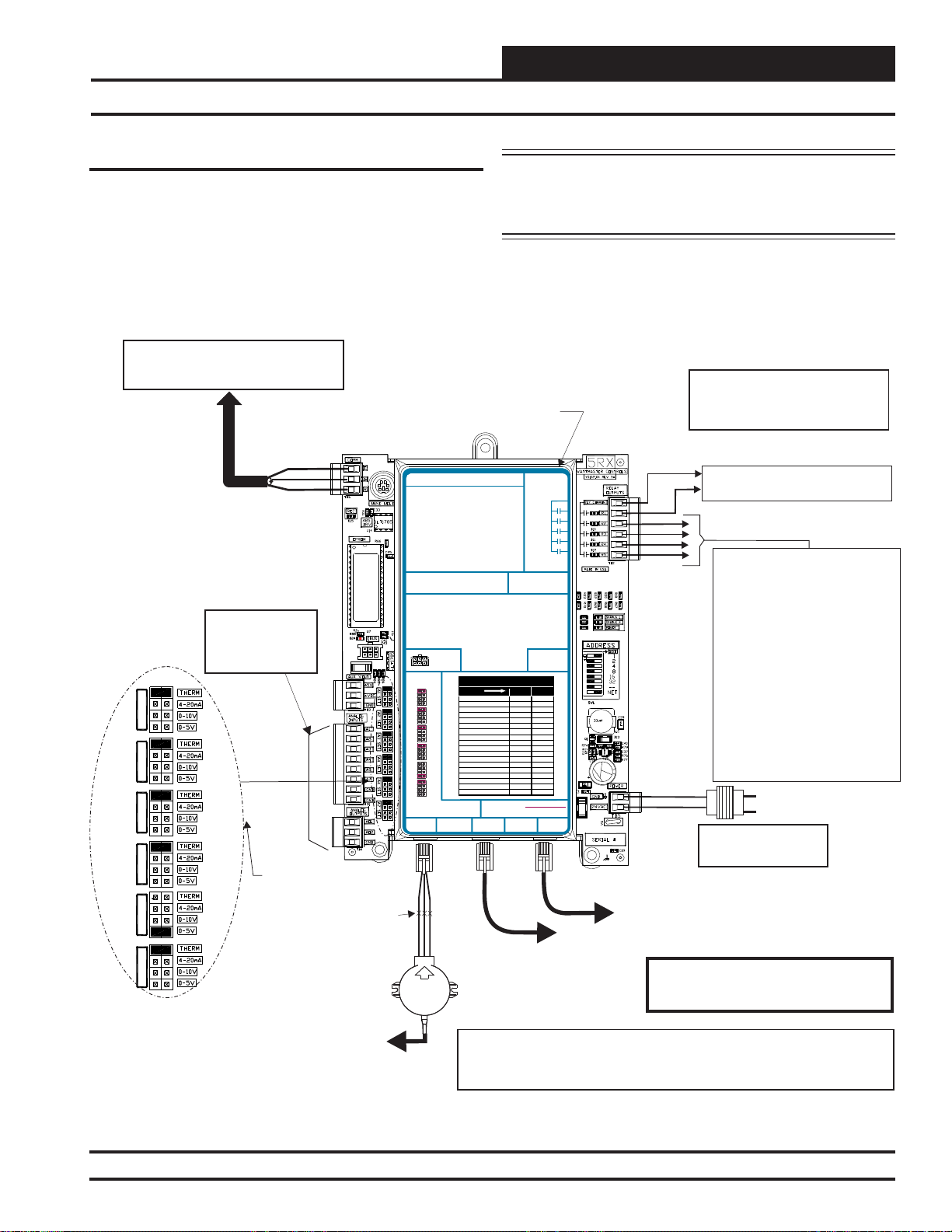
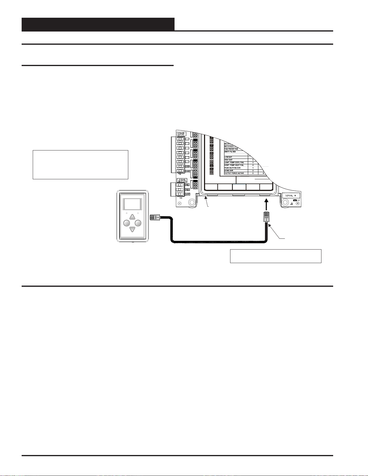
SA E-BUS Controller Wiring
SA E-BUS Controller
The Series A Controller (OE332-23E-SA)—SA E-BUS Controller—is
designed with 6 analog inputs, 2 analog outputs, and 5 relay outputs.
Most common HVAC unit control applications can be confi gured us-
ing only the SA E-BUS Controller; however, if needed, the SA E-BUS
Controller’s input and output capabilities can be expanded with the SA
Expansion Module ( OE333-23-SA) or 12-Relay Expansion Module
( OE358-23-12R) by means of a modular cable.
For Stand Alone Applications,
Connect To System Manager. For Network
Applications Connect To Next Controller And/Or
MiniLink PD On Local Loop.
SA E-BUS Controller
RS-485 COMMUNICATION LOOP. WIRE
“R” TO “R”, “T”TO “T” “SHLD” TO “SHLD”
SA CONTROLLERE-BUS
Orion No.:OE332-23E-VCMX-SA
AI1 = SPC (SPACETEMPERATURE SENSOR)
AI2
= SAT(SUPPLY AIR TEMPERATURE SENSOR)
AI3
= EWT (ENTERING WATERTEMPERATURE SENSOR)
AI4
= EAT(ENTERING AIR TEMPERATURE SENSOR)
AI5
= NOT USED
AI7
= SPACETEMPERATURE SENSOR SLIDE ADJUST
OR VOLTAGE RESETSOURCE
A01
= WATER SIDE ECONOMIZER VALVE 1A &1B (2-10 VDC)
A02
= SUPPLYFAN VFD (0-10 VDC OUTPUT)
E-BUS
CONNECTOR
ANALOG INPUT
JUMPER
SETTINGS
THERM
LED NAME STATUS1 STATUS2
4-20mA
AI1
AI2
AI3
AI4
AI5
AI7
ANALOG INPUTJUMPER SETTINGS
MUSTBE SET AS SHOWN FOR
PROPER OPERATION
STATIC
PRESSURE
NORMALOPERATION 0 1
0-10V
0-5V
SATFAIL 1 2
THERM
EATFAIL 2 2
4-20mA
SPCFAIL 3 2
0-10V
MECHCOOL FAIL 1 3
0-5V
MECHHEAT FAIL 2 3
THERM
4-20mA
FANPROOF FAIL 3 3
0-10V
DIRTYFILTER 4 3
0-5V
WATERFLOW ALARM 6 3
THERM
DRAINPAN ALARM 7 3
4-20mA
0-10V
EMERGENCYSH UTDOWN 5 3
0-5V
LOWSAT 1 4
THERM
HIGHSAT 2 4
4-20mA
CONT.TEMP COOL FAIL 3 4
0-10V
CONT.TEMP H EAT FAIL 4 4
0-5V
PUSHBUTTON OVR 1 5
THERM
4-20mA
ZONEOVR 2 5
0-10V
OUTPUTFORCE ACTIVE 0 6
0-5V
WattMaster Label
#LB102060-01-A
Rev.: 1A
EXPANSION
All Comm Loop Wiring Is
Straight Thru
T to T, R to R & SHLD to SHLD
See Individual
Component Wiring
Diagrams For Detailed
Wiring Of Analog Inputs
And Outputs
AI1 SET AI2 SET AI3 SET
AI4 SET AI5 SET AI7 SET
Local Loop
RS-485
9600 Baud
Jumpers
NOTE: Only one SA E-BUS Controller is required whether
the SA Unit is a Single Cabinet or Dual Cabinet Unit. Additional
wiring for Dual Cabinet Units is shown and noted as such on the
applicable Single Cabinet Unit Diagrams.
Note:
All Relay Outputs Are Normally Open
And Rated For 24 VAC Power Only.
1 Amp Maximum Load.
RELAYCONTACT
RATING IS 1AMP
MAX @ 24 VAC
RELAY
COMMON
FAN
RELAY2
RELAY3
RELAY4
RELAY5
AAON No.:
V07160
LED BLINK CODES
24 VAC POWER ONLY
WARNING!POLARITY MUST BE OBSERVED
OR THE CONTROLLER WILLBE DAMAGED
2
IC
2
IC DIGITAL
SENSOR
R - 24VAC
G - Fan ON/OFF Only
Relay Output Contacts
R2 Thru R5 May Be User Configured
For The Following:
1 - Heating Stages
2 - Cooling Stages
3 - Warm-up Mode Command
(VAV Boxes)
4 - Reversing Valve (Air To Air Heat
Pumps)
5 - Reheat Control (Dehumidification)
6 - Preheater For Low Ambient
Protection
7 - Alarm
8 - Override
9 - Occupied
10 - Water Side Economizer
A Total Of 20 Relays Are Available
Note:
By Adding Expansion Modules.
Expansion Module Relay Outputs Are
User-Configurable As Listed Above.
GND
Line Voltage
24VAC
Size Transformer For
Correct Total Load.
SA Controller = 8 VA
Splice If Required
Connect To
Expansion Module
(When Used)
OE271
Static Pressure
Transducer
Connect FRP Tubing To High Pressure
Port (Bottom Tube) and Route To Static
Pressure Pickup Probe Located In Unit
Discharge. Leave Port Marked “Lo” Open
To Atmosphere
Note:
Only One SA Controller is Required Whether The SA Unit is a Single Cabinet
Or Dual Cabinet Unit. Additional Wiring For Dual Cabinet Units is Shown and
Noted As Such On The Applicable Single Cabinet Unit Diagrams.
Figure 5: OE332-23E-SA E-BUS Controller – SA E-BUS Controller Wiring
SA E-BUS Controller Technical Guide
Connect To Digital Room Sensor - See Digital Room Sensor
Wiring Diagram.
Warning:
24 VAC Must Be Connected So That All Ground
Wires Remain Common. Failure To Do So Will
Result In Damage To The Controllers.
11
Page 12
Installation & Wiring
Digital Room Sensor Wiring
Digital Room Sensor
The OE217-00 Digital Room Sensor is used to sense Space Temperature
and the OE217-01 Digital Room Sensor is used to sense Space Temperature and Space Humidity. The Sensor connects to the SA E-BUS
Controller with the TSDRSC modular cable. It should be mounted at approximately 5 ft. above the fl oor on the wall in an area that does not have
drafts or is exposed to direct sunlight. See Figure 6 for wiring details.
Note: The Connects
Directly To The Controller Using
TSDRSC Cable
A Of The Appropriate
Length.
160 Feet.
Digital Room Sensor
SA E-BUS
The Maximum Length Allowed Is
Zone
Zone
I1 SET
AI1
AI2 SET AI3 SET
AI2
AI3
AI4
AI5
AI4 SET AI5 SET AI7 SET
AI7
4-20mA
AI2
0-10V
0-5V
THERM
4-20mA
AI3
0-10V
0-5V
THERM
EMERGENCY SHUTDOWN
4-20mA
AI4
0-10V
0-5V
THERM
4-20mA
AI5
0-10V
0-5V
THERM
4-20mA
AI7
0-10V
0-5V
ANALOG INPUT JUMPER SETTINGS
MUST BE SETAS SHOWN FOR
PROPER OPERATION
STATIC
WattMaster Label
#LB102033-01
PRESSURE
24 VAC POWER ONLY
WARNING!POLARITY MUST BE OBSERVED
OR THE CONTROLLER WILL BE DAMAGED
I2C
EXPANSION
I2C DIGITAL
SENSOR
OVERRIDE ALARM
Display
Override
Digital Room Sensor
Figure 6: OE217-00 & OE217-01 – Digital Room Sensor Wiring
SA E-BUS Controller
TSDRSC Cable
Note: No Additional Wiring is Required For
Dual Cabinet Units.
12
SA E-BUS Controller Technical Guide
Page 13
Installation & Wiring
GND
TMP
Space Temperature Sensor
OVR
R
E
L
O
C
R
E
M
R
O
A
W
AUX
Wire Required For
Sensors With Slide
Adjust Option Only
Set Jumper For THERM
When Space Sensor Slide
Adjust Is Wired To AI7
AI1
AI1 SET AI2 SET AI3 SET
AI4 SET AI5 SET AI7 SET
AI2
AI3
AI4
AI5
AI7
Note:
Either The Slide Offset Option For The Space
Temperature Sensor Or The Remote Supply
Air Temperature Reset Signal Option (By
Others) May Be Connected To An AI7 On
The SA E-BUS Controller. Only One Option
Is Allowed, Not Both.
AI1
AI7
GND
SA E-BUS Controller
Note: No Additional Wiring is
Required For Dual Cabinet
Units.
AI7 SET
Remote Supply Air
Temperature Reset Signal
(By Others)
0-5 VDC or 0-10 VDC Signal
GND
Note:
Either The Slide Offset Option For The Space Temperature
Sensor Or The Remote Supply Air Temperature Reset
Signal Option (By Others) May Be Connected To AI7 On
The SA E-BUS Controller. Only One Option Is Allowed,
Not Both.
Regardless of Whether the Remote
SAT Reset Signal Has Been
Configured For 0-5 or 0-10 VDC,
Jumper Must Be Set For 0-10V
AI7
GND
SA E-BUS Controller
AI1
AI1 SET AI2 SET AI3 SET
AI4 SET AI5 SET AI7 SET
AI2
AI3
AI4
AI5
AI7
Note: No Additional Wiring
is Required For Dual Cabinet
Units.
AI7 SET
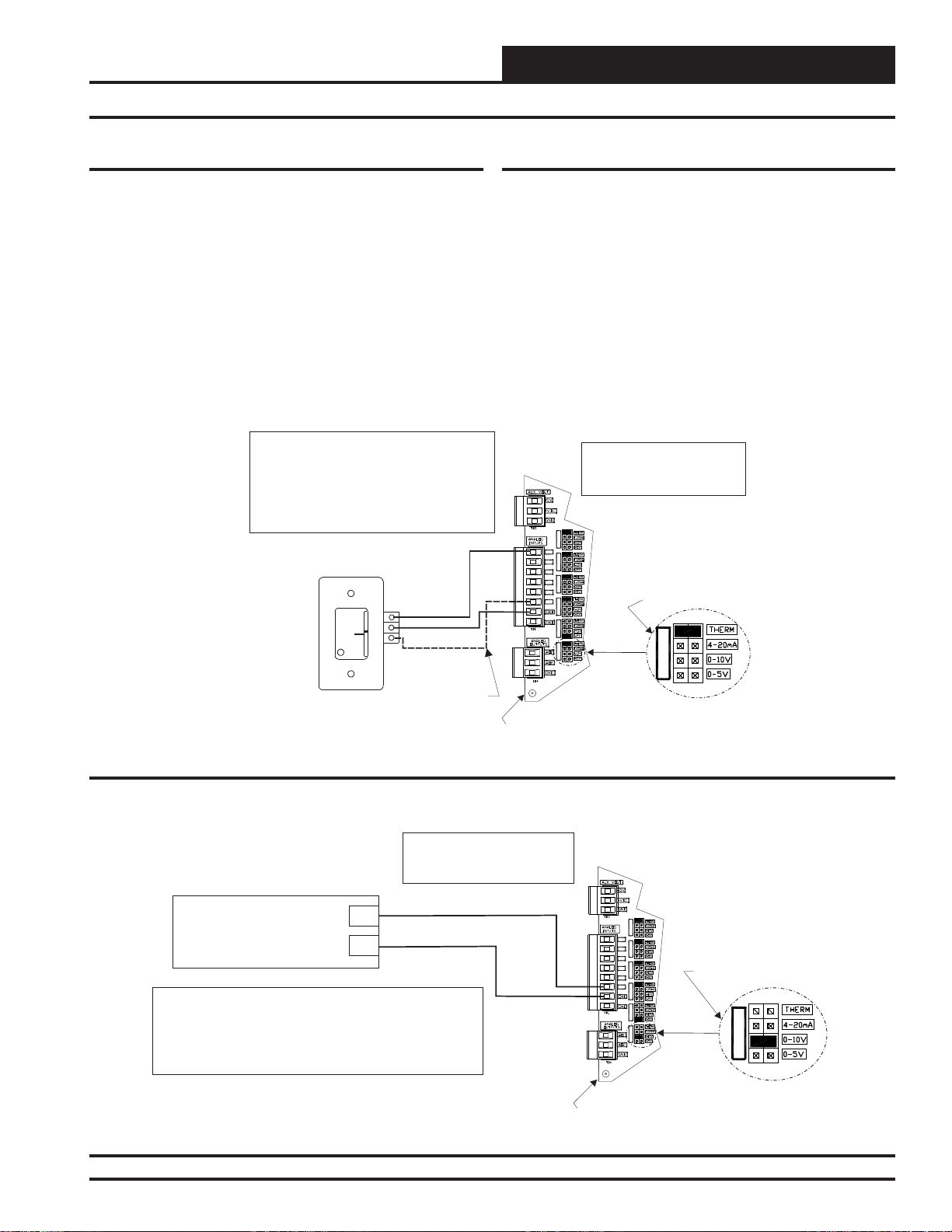
SAT & Remote SAT Reset Signal Wiring
Space Temperature Sensor
The OE210, OE211, OE212, OE213 Space Temperature Sensor is typically used for constant volume HVAC unit applications controlling one
zone. The Space T emperature Sensor is a 10K T ype III thermistor sensor
and should be mounted approximately 5 feet above the fl oor in the space
that is to be controlled. The Space Temperature Sensor is available as a
sensor only, sensor with override button, sensor with slide adjust, and
sensor with slide adjust and override confi gurations.
When the Remote Supply Air T emperature Reset Signal option is needed,
the Slide Offset option on the Room Sensor cannot be used. Only one
of these options may be used on the SA E-BUS Controller.
See Figure 7 below for complete Space Temperature Sensor wiring
details.
Remote SAT Reset Signal
A Remote Supply Air T emperature Reset Signal can be connected to AI7
for applications requiring remote reset of the Supply Air Temperature
Setpoint.
When the Slide Offset option on the Room Sensor is used, the Remote
Supply Air Temperature Reset Signal cannot be used. Only one of these
options may be used on the SA E-BUS Controller.
The SA E-BUS Controller can accept either a 0-5 VDC signal or a 0-10
VDC signal on this input.
See Figure 8 below for complete Remote SAT Reset Signal wiring
details.
Figure 7: OE210, OE211, OE212, OE213 – Space Temperature Sensor Wiring
Figure 8: Remote Supply Air Temperature Reset Signal Wiring
SA E-BUS Controller Technical Guide
13
Page 14
Installation & Wiring
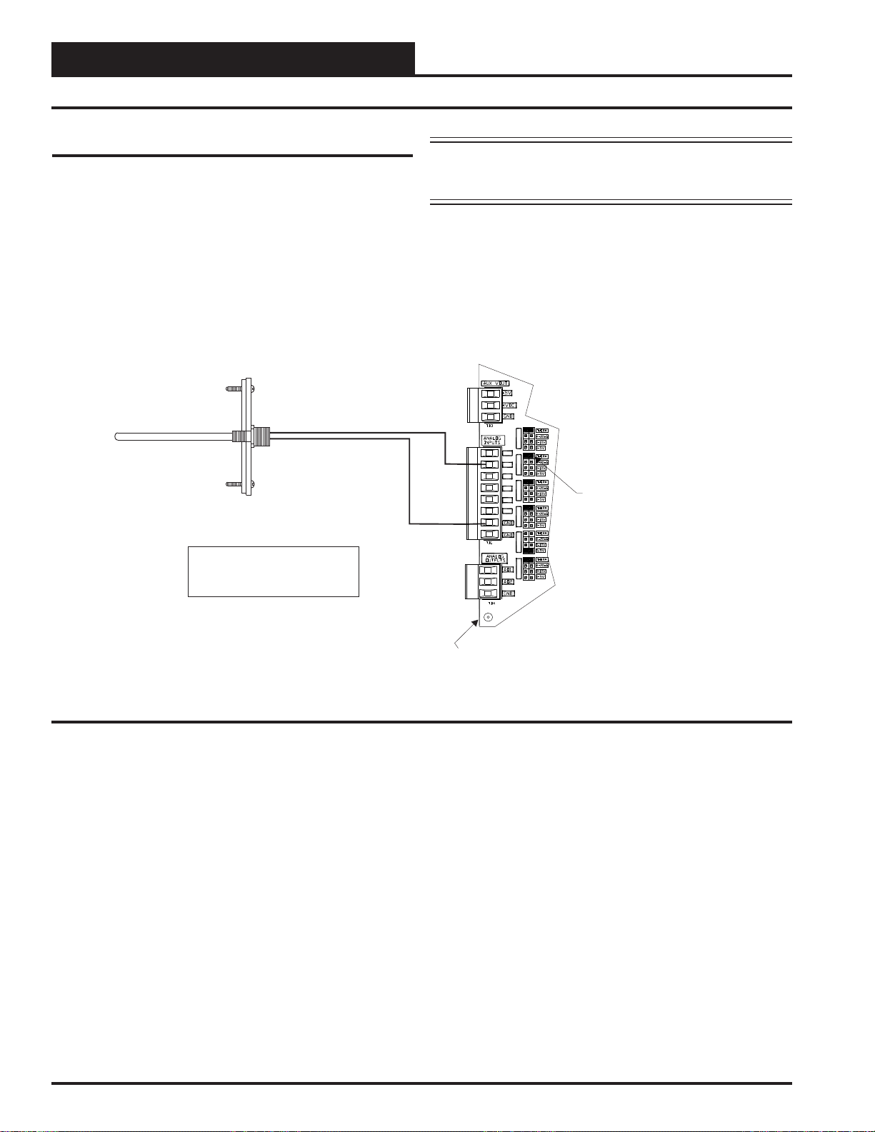
SAT Sensor Wiring
Zone
Zone
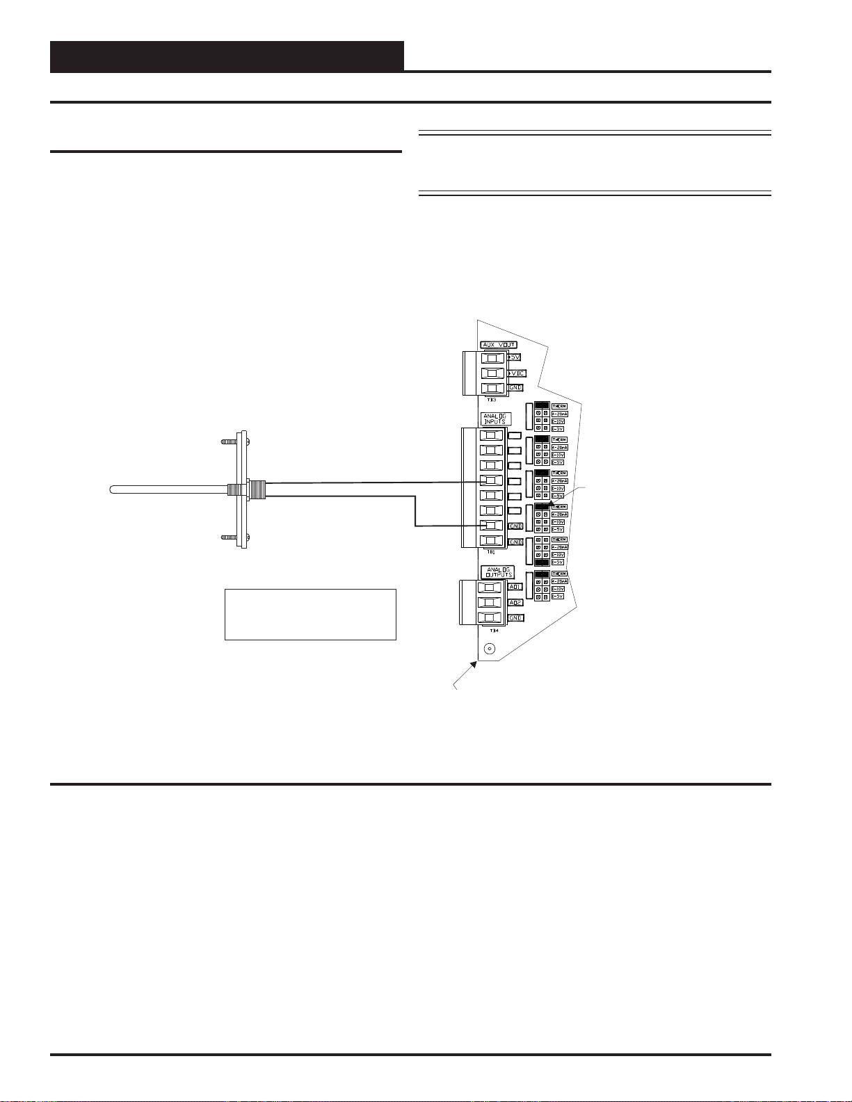
Supply Air Temperature Sensor
The OE231 Supply Air Temperature Sensor must be wired as shown
in Figure 9 below for proper operation. The Supply Air Temperature
Sensor is a 10K Type III thermistor sensor. The Supply Air Temperature Sensor should be mounted in the unit discharge plenum or in the
supply air duct.
Supply Air Temperature Sensor
Mount In HVAC
Unit Supply
Air Duct
Note: No Additional Wiring
is Required For Dual Cabinet
Units.
NOTE: For Dual Cabinet Units, mount the Supply Air
Temperature Sensor in a Supply Air Ducting area that is common
to both SA Units.
AI1 SET AI2 SET AI3 SET
AI2
GND
AI1
AI2
AI3
AI4
AI5
AI4 SET AI5 SET AI7 SET
AI7
Be Sure The Jumper Is
Set For THERM On AI2 For
Supply Air Temperature
Sensor When Used
Figure 9: OE231 – Supply Air Temperature Sensor Wiring
SA E-BUS Controller
14
SA E-BUS Controller Technical Guide
Page 15
Installation & Wiring
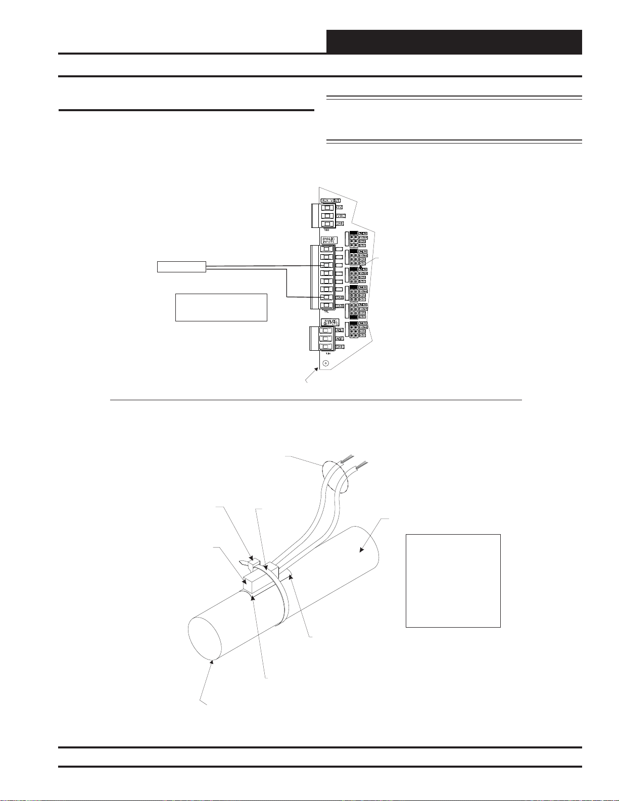
Entering Water Temperature Sensor Wiring
Entering Water Temperature Sensor
The OE233 Entering W ater T emperature Sensor must be wired as shown
in Figure 10 below for proper operation. The Entering Water Tempera-
ture Sensor is a 10K Type III thermistor sensor. The Entering Water
Temperature Sensor should be mounted in the entering water piping.
Entering Water
Temperature Sensor
(Strap On)
Note: No Additional Wiring
is Required For Dual Cabinet
Units.
AI3
GND
NOTE: For Dual Cabinet Units, mount the Entering Water
Temperature Sensor in an Entering Water Piping area that is
common to both SA Units.
AI1 SET AI2 SET AI3 SET
AI1
AI2
AI3
AI4
AI5
AI4 SET AI5 SET AI7 SET
AI7
SA E-BUS Controller
Be Sure Jumper Is Set
For THERM
On AI3 For Entering
Water Temperature Sensor
Butt Splice Or Wire Nut Wire Leads And
Extend Wire To Controller Terminals. Connect
One Wire Lead To Entering Water
Temperature Terminal (AI3) At The Controller.
Secure Other Wire Lead To Ground Terminal
At The Controller. See Note 3.
Secure Sensor Element And Thermal
Mastic Strip To Pipe With Supplied
Wire Tie. Be Sure To Tighten Wire Tie
Snugly To Ensure Good Thermal
Contact.
Sensing Element
(Supplied)
Entering Water Temperature Sensor
Wire Tire
(Supplied)
Thermal Mastic Strip
(Supplied)
Notes:
1.)Sensor Should Be Mounted At
Location Along Pipe Length
That Best Represents Desired
Temperature Reading.
2.)Sensing Element Shown
Mounted To Top Of Pipe. The
Sensor Element May Be Located
At Any Location Around Pipe.
3.)All Wiring To Be In Accordance
With Local And National Electrical
Codes And Specifications.
Entering Water Pipe
See Note 1 & 2.
Thermal Mastic
Place Between Pipe
And Sensing Element. Pipe Should
Be Clean And Smooth To Provide
Proper Thermal Contact With
Sensing Element.
Caution:
For Accurate Temperature
Readings It Is Necessary To
Place Insulation Over The
Sensor After Installation.
This Prevents The Ambient
Temperature From Affecting
The Sensor. Insulation
Should Cover The Sensor
And Extend 6“ to 12”
Beyond Each End Of The
Sensor.
Figure 10: OE233 – Entering Water Temperature Sensor Installation & Wiring
SA E-BUS Controller Technical Guide
15
Page 16
Zone
Installation & Wiring
Entering Air Temperature Sensor Wiring
Zone
Entering Air Temperature Sensor
The OE231 Entering Air Temperature Sensor must be wired as shown
in Figure 11 below for proper operation of the SA E-BUS Controller.
The Entering Air Temperature Sensor is a 10K Type III thermistor sensor. The sensor should be mounted as shown in an area that is protected
from the elements and direct sunlight.
Entering Air
Temperature Sensor
Mount In Entering
Air Stream
NOTE: For Dual Cabinet Units, mount the Entering Air
Temperature Sensor in an Entering Air Duct area that is common
to both SA Units.
AI1 SET AI2 SET AI3 SET
AI1
AI2
AI4
GND
AI3
AI4
AI5
AI4 SET AI5 SET AI7 SET
AI7
Be Sure Jumper Is Set
For THERM
On AI4 For Entering
Air Temperature Sensor
Note: No Additional Wiring
is Required For Dual Cabinet
Units.
Figure 11: OE231 – Entering Air Temperature Sensor Wiring
SA E-BUS Controller
16
SA E-BUS Controller Technical Guide
Page 17
Installation & Wiring
3 (Y)
3 (Y)
5 (U)
5 (U)
2 (+)
2 (+)
1 (-)
1 (-)
Water Side Economizer Wiring
Water Side Economizer (WSE) Valve(s)
The Water Side Economizer Valve(s) must be wired as shown in Figure
12 below for proper operation of the SA E-BUS Controller. The Water
Side Economizer V alve(s) connects to AO1 on the SA E-BUS Controller .
NOTE: For Dual Cabinet Units, wire the Second Cabinet’s WSE
Valve Actuator in parallel with the First Cabinet’s WSE Valve
Actuator.
Note: Required For Dual SA Unit
Applications Only.
WSE Valve 1B - Actuator
GND
24 VAC
2-10 VDC
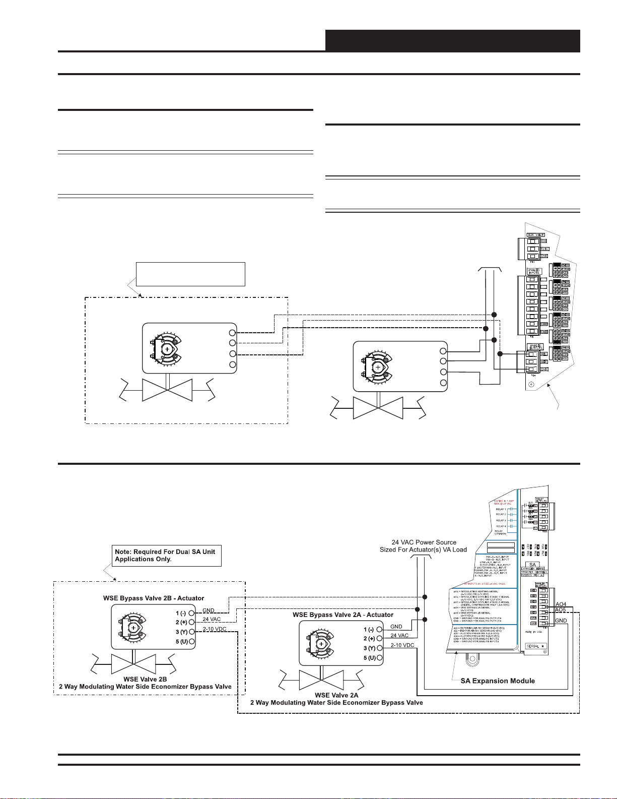
Water Side Economizer (WSE) Bypass
Valve
The W ater Side Economizer Bypass Valve(s) must be wired as shown in
Figure 13 below for proper operation of the SA E-BUS Controller. The
W ater Side Economizer Bypass Valve(s) are wired to AO4 and AO5 on
the SA Expansion Module.
NOTE: For Dual Cabinet Units, wire the Second Cabinet’s WSE
Bypass Valve Actuator to AO5 on the SA Expansion Module.
24 VAC Power Source
Sized For Actuator(s) VA Load
WSE Valve 1A - Actuator
GND
24 VAC
2-10 VDC
AO1
GND
AI1 SET AI2 SET AI3 SET
AI1
AI2
AI3
AI4
AI5
AI4 SET AI5 SET
AI7
AI7 SET
2 Way Modulating Water Side Economizer Valve
WSE Valve 1B
2 Way Modulating Water Side Economizer Valve
Figure 12: Water Side Economizer Valve Wiring
Figure 13: Water Side Economizer Bypass Valve Wiring
SA E-BUS Controller
WSE Valve 1A
SA E-BUS Controller Technical Guide
17
Page 18
Installation & Wiring
+
+
_
_
Supply Fan VFD Signal
Zone
Zone
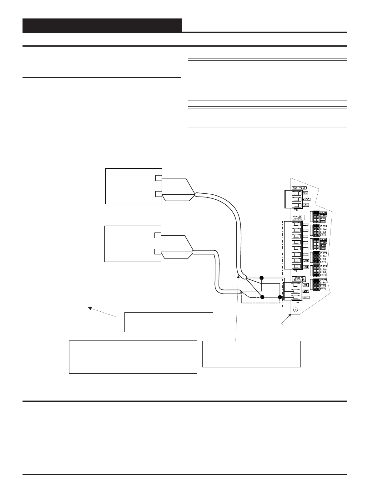
Supply Fan VFD Signal or Zoning
Bypass Damper Actuator Signal
The Supply Fan VFD or Zoning Bypass Damper Actuator Signal is a
0-10 VDC output from AO2 on the SA E-BUS Controller. This signal
output can be connected to the Supply Fan Variable Frequency Drive to
modulate the Supply Fan speed and control Duct Static Pressure utilizing
the Duct Static Pressure Sensor connected to the SA E-BUS Controller .
Alternatively, it can be connected to a Zoning Bypass Damper Actuator
that will modulate the Zoning Bypass Damper Actuator to control Duct
Static Pressure utilizing the Duct Static Pressure Sensor connected to the
SA E-BUS Controller . A Duct Static Pressure Sensor must be connected
in order for the VFD or Zoning Bypass Damper Actuator to operate. See
Figures 14 and 15 for detailed wiring.
0-10 VDC Input From AO2
GND
Shield
Supply Fan Variable Frequency Drive #1
(By Others)
0-10 VDC Input From AO2
GND
Shield
Caution: Variable Frequency Drive units can cause large transient
noise spikes which can cause interference to be propagated on other
electronic equipment. Use shielded wire wherever possible and route
all sensor and controller wiring away from the Variable Frequency
Drive and the HVAC Unit electrical wiring.
NOTE: For Dual Cabinet Units, VFD #2 must be wired in
parallel to VFD #1 as shown in Figure 14 below.
AI1 SET AI2 SET AI3 SET
AI1
AI2
AI3
AI4
AI5
AI4 SET AI5 SET AI7 SET
AI7
Supply Fan Variable Frequency Drive #2
Caution:
The VFD Unit Must Be Configured For 0-10 VDC Input.
The Input Resistance At The VFD Must Not Be Less
Than 1000 Ohms When Measured At The VFD
Terminals With All Input Wires Removed.
Figure 14: Supply Fan VFD Wiring
(By Others)
Note: Required For Dual SA Unit
Applications Only.
Note:
Wire To The VFD Using 18 GA Minimum 2
Conducter Twisted Pair With Shield Cable.
Wire Shield To GND As Shown
AO2
GND
Shield
SA E-BUS Controller
18
SA E-BUS Controller Technical Guide
Page 19
3 (Y)
5 (U)
2 (+)
1 (-)
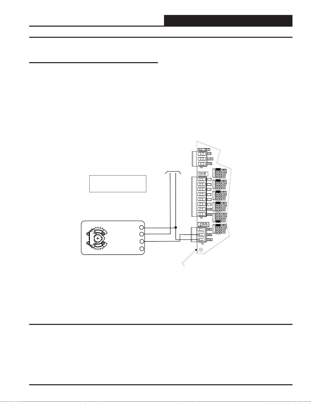
Supply Fan VFD Signal or Zoning
Bypass Damper Actuator Signal
When the Bypass Damper is used (Zoning applications), be sure the
Bypass Duct and Damper are designed so that Supply Air will bypass
to the Entering Air Duct, ensuring equal airfl ow to both cabinets.
24 VAC Power Source
Sized For Actuator VA Load
Installation & Wiring
Zoning Bypass Damper Actuator
AI1 SET AI2 SET AI3 SET
Note: No Additional Wiring
is Required For Dual Cabinet
Units.
Bypass Damper Actuator
(Belimo Actuator Shown)
GND
24 VAC
0-10 VDC
Belimo Actuator Wiring
Shown. Consult Factory For
Other Manufacturer Wiring
Instructions
Figure 15: Zoning Bypass Damper Actuator Wiring
AI1
AI2
AI3
AI4
AI5
AI4 SET AI5 SET AI7 SET
AI7
AO2
GND
SA E-BUS Controller
SA E-BUS Controller Technical Guide
19
Page 20
Installation & Wiring
SA Expansion Module Input Wiring
Zone
Zone
SA Expansion Module
Two different Expansion Modules are available for use with the SA EBUS Controller to provide additional inputs and outputs beyond those
found on the SA E-BUS Controller.
The SA Expansion Module ( OE333-23-SA E-BUS Controller) provides
8 Binary Inputs, 4 Analog Inputs, 5 Analog Outputs, and 4 Confi gurable
Relay Outputs. See Figures 16 and 17 for complete wiring details.
10 VA Minimum Power Required
For SA Expansion Module
See Suction Pressure
Transducer Wiring Details For
Complete Wiring Information.
See Humidity Sensor Wiring
Details For Complete Wiring
Information.
Entering Air
Humidity Sensor
VAC OR DC
GND
0-5V
Indoor Air
Humidity Sensor
VOUT (0-5V)
GND
24 VAC
GND
Additional Suction
Pressure Sensor Required
On Dual Units Only.
Suction Pressure
Transducer #2
Suction Pressure
Transducer #1
Splice Wire As Required To Reach
From Transducer Location To
Expansion Module Location
Water Proof of Flow A- N.O. Input
Water Proof of Flow B - N.O. Input
Air Proof Of Flow - N.O. Input
Remote Forced Occupied - N.O. Input
Emergency Shutdown - N.C. Input
Drain Pan Overflow A - N.O. Input
Drain Pan Overflow B - N.O. Input
Dirty Filter - N.O. Input
VIN
WH
BK
RD
RD
WH
BK
The 12-Relay Expansion Module ( OE358-23-12R) provides for 12
Dry Contact Confi gurable Relay Outputs. See Figure 25 for complete
wiring details.
The expansion modules can be used individually or together to provide
the required inputs and outputs for your specifi c applications.
WARNING!!
Observe Polarity! All boards must be wired with GND-to-GND and 24VAC-to24VAC. Failure to observe polarity will result in damage to one or more of the
boards. Expansion Module must be wired in such a way that the expansion
module and the controller are always powered together. Loss of power to the
expansion module will cause the controller to become inoperative until power is
restored to the expansion module.
24 VAC
GND
GND
24 VAC POWER ONLY
POWER ONLY
WARNING!POLARITY MUST BE
WARNING!
OBSERVED OR THE BOARD
POLARITY
WILL BE DAMAGED
MUST BE
OBSERVED OR
POLARITY
WARNING
OBSERVE
THE BOARD
WILL BE
DAMAGED
SA Expansion Module
Orion No.:OE333-23-SA
OE333-23-EM-AVCM-X EXPANSION MODULE
PR OUT
GND
SUCTION PRESSURE
+V
TRANSDUCER CONNECTION
SIG
FOR HVAC UNITS WITHOUT
GND
DIGITALCOMPRESSOR
RELAY1 = RELAY3 =
B 1I
B 2I
B 3I
B 4I
B 5I
B 6I
B 7I
BI8
AI1
AI2
AI3
AI4
RELAY2 = RELAY4 =
RELAY1 = RELAY 3 =
ITIS SUGGESTED
THATYOU WRITE THE
DESCRIPTION OF
RELAY2 = RELAY 4 =
THE RELAYOUTPUTS
YOUARE USING IN
ITIS SUGGESTED
THE BOXES
THATYOU WRITE THE
PROVIDEDABOVE
DESCRIPTION OF
WITHA PERMANENT
THE RELAYOUTPUTS
MARKER (SHARPIE®)
YOUARE USING IN
THE BOXES
PROVIDEDABOVE
WITHA PERMANENT
ANALOG INPUT
MARKER (SHARPIE®)
JUMPER SETTINGS
MUST BE SETAS
SHOWN FOR
PROPER
ANALOG INPUT
OPERATION
JUMPER SETTINGS
MUST BE SETAS
SHOWN FOR
PROPER
ANALOG INPUT
OPERATION
JUMPER
SETTINGS
THERM
ANALOG INPUT
4-20mA
JUMPER
AI1
0-10V
SETTINGS
0-5V
THERM
THERM
4-20mA
4-20mA
AI1
AI2
0-10V
0-10V
0-5V
0-5V
THERM
THERM
4-20mA
AI2
4-20mA
0-10V
AI3
0-10V
0-5V
0-5V
THERM
THERM
4-20mA
AI3
4-20mA
0-10V
AI4
0-10V
0-5V
0-5V
THERM
4-20mA
AI4
0-10V
I2C
0-5V
EXPANSION
I2C
WattMaster Label
EXPANSION
#LB102034-01
AAON No.:
R96180
www.orioncontrols.com
RELAYCONTACT
RATING IS 1AMP
MAX @ 24 VAC
TO VCM-X INPUT
TERMINALS AI5 & GND
BI1 = WATER PROOF OF FLOW -A - N.O. INPUT
= WATER PROOF OF FLOW - B - N.O. INPUT
BI2
= AIR PROOF OF FLOW - N.O. INPUT
BI3
= REMOTE FORCED OCCUPIED - N.O. INPUT
BI4
BI1 = HOOD ON - N.O. INPUT
= EMERGENCY SHUTDOWN - N.C. INPUT
BI5
= DIRTY FILTER - N.O. INPUT
BI2
= DRAIN PAN OVERFLOW -A - N.O. INPUT
BI6
= PROOF OF FLOW - N.O. INPUT
BI3
= DRAIN PAN OVERFLOW - B - N.O. INPUT
BI7
= REMOTE FORCED OCCUPIED - N.O. INPUT
BI4
= DIRTY FILTER - N.O. INPUT
BI8
= REMOTE FORCED HEATING - N.O. INPUT
BI5
= REMOTE FORCED COOLING - N.O. INPUT
BI6
NOTE:
= SMOKE DETECTOR - N.C. INPUT
BI7
ALL BINARY INPUTS MUSTBE 24 VAC ONLY.
= REMOTE DEHUMIDIFICATION - N.O. INPUT
BI8
NOTE:
AO1 = MODULATING HEATING SIGNAL
ALL BINARYINPUTS MUST BE 24 VAC ONLY.
(0-10 VDC OR 2-10 VDC)
AO2
= MODULATING COOLING STAGE 1 SIGNAL
(0-10 VDC, 2-10 VDC OR 1.5-5 VDC)
AO1 = BUILDING PRESSURE CONTROL VFD OR
AO3
= MODULATING COOLING STAGE 2 SIGNAL
DAMPER ACTUATOR (0-10 OR 2-10 VDC)
(DIGITALCOMPRESSOR ONLY 1.5-5 VDC)
AO2
= MODULATING HEATING SIGNAL
= WSE BYPASS 2ASIGNAL
AO4
(0-10 VDC OR 2-10 VDC)
(0-10 VDC)
AO3
= MODULATING COOLING/DIGITALSCROLL
= WSE BYPASS 2B SIGNAL
AO5
SIGNAL (0-10 VDC, 2-10 VDC OR 1.5-5 VDC)
(0-10 VDC)
AO4
= RETURN AIR DAMPERACTUATOR
GND
= GROUND FOR ANALOG OUTPUTS
(0-10 VDC)
GND
= GROUND FOR ANALOG OUTPUTS
AO5
= RETURN AIR BYPASS DAMPERACTUATOR
(0-10 VDC)
GND
= GROUND FOR ANALOG OUTPUTS
AI1 = ENTERING AIR RH SENSOR (0-5 VDC)
GND
= GROUND FOR ANALOG OUTPUTS
= INDOOR AIR RH SENSOR (0-5 VDC)
AI2
= SUCTION PRESSURE A(0-5 VDC)
AI3
= SUCTION PRESSURE B (0-5 VDC)
AI4
AI1 = OUTDOOR AIR RH SENSOR (0-5 VDC)
= GROUND FOR ANALOG INPUTS
GND
AI2
= INDOOR AIR RH SENSOR (0-5 VDC)
= GROUND FOR ANALOG INPUTS
GND
AI3
= CO2 (0-10 VDC)
AI4
= BUILDING STATIC PRESSURE (0-5 VDC)
GND
= GROUND FOR ANALOG INPUTS
GND
= GROUND FOR ANALOG INPUTS
EXPANSION
RELAYCONTACT
RATING IS 1AMP
MAX @ 24 VAC
RELAY1
RELAY2
RELAY3
RELAY
RELAY4
COMMON
RELAY
COMMON
WattMaster Label
I2C
#LB102061-A
Rev.: 1C
EXPANSION
RELAY1
RELAY2
RELAY3
RELAY4
I2C
SA
SA Expansion Module
Figure 16: OE333-23-SA – SA Expansion Module Input Wiring
20
SA E-BUS Controller Technical Guide
Modular Cable
Connect To SA E-BUS
Controller
Modular Cable
Connect To Next Expansion
Module (When Used)
Page 21
Installation & Wiring
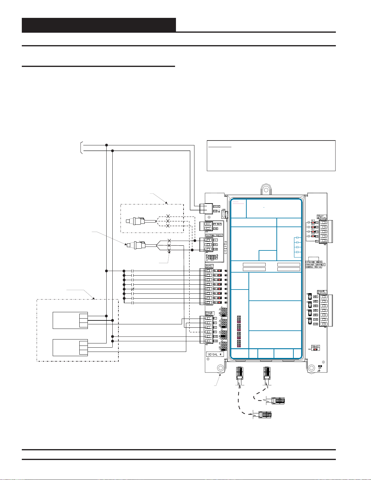
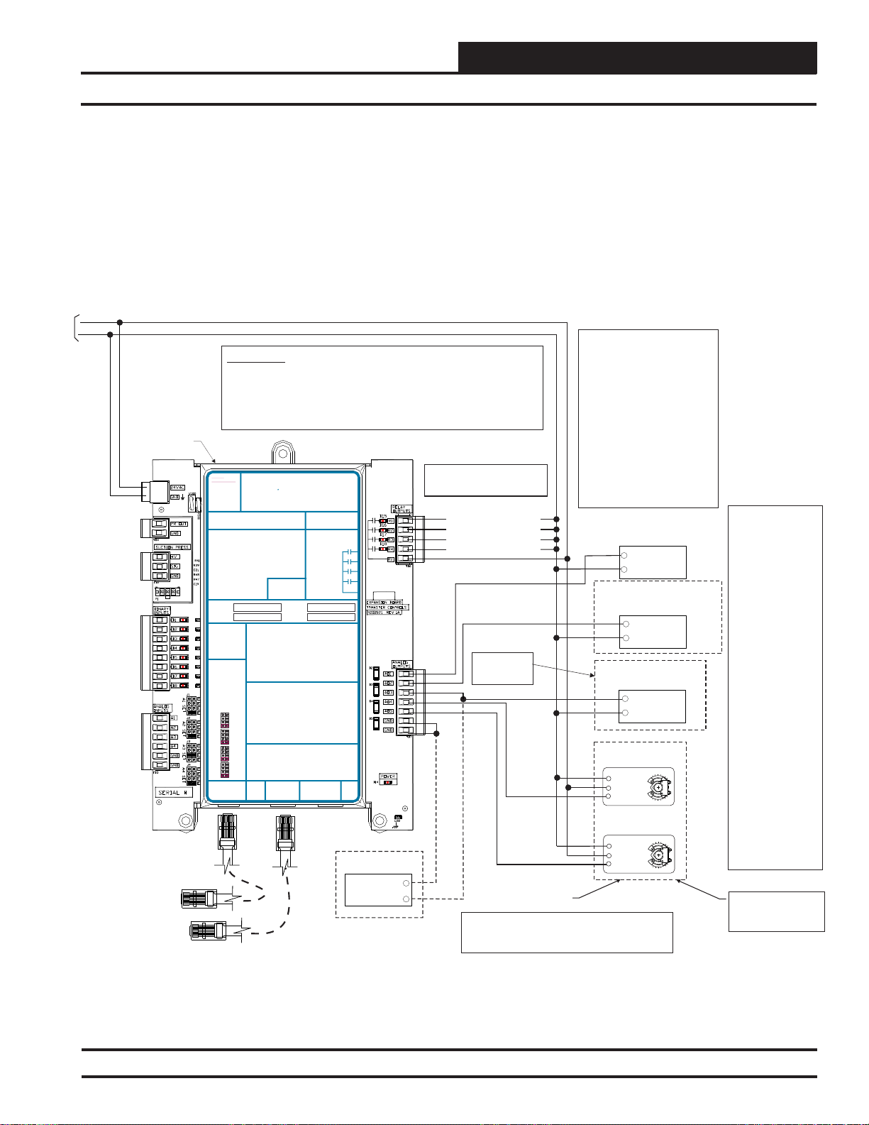
SA Expansion Module Output Wiring
The SA Expansion Module must be connected to 24 VAC as shown in
the wiring diagram below. Please see Table 1 on page 10 for correct VA
requirements to use when sizing the transformer(s) used for powering
the expansion module.
24 VAC
GND
10 VA Minimum Power
Required For SA
Expansion Module
SA Expansion
Module
POLARITY
WARNING
OBSERVE
Modular Cable
Connect To Expansion
Module (When Used)
Modular Cable
Connect To SAE-BUS
Controller
WARNING!!
Observe Polarity! All boards must be wired with GND-to-GND and 24VACto-24VAC. Failure to observe polarity will result in damage to one or more of
the boards. Expansion Module must be wired in such a way that the
expansion module and the controller are always powered together. Loss of
power to the expansion module will cause the controller to become
inoperative until power is restored to the expansion module.
24 VAC
24 VAC POWER ONLY
POWER ONLY
WARNING!POLARITY MUST BE
WARNING!
OBSERVED OR THE BOARD
POLARITY
WILLBE DAMAGED
MUST BE
OBSERVED OR
THE BOARD
WILLBE
DAMAGED
SA Expansion Module
Orion No.:OE333-23-SA
OE333-23-EM-AVCM-X EXPANSION MODULE
PR OUT
GND
+V
SIG
GND
RELAY1 = RELAY 3 =
RELAY2 = RELAY 4 =
RELAY1 = RELAY 3 =
ITIS SUGGESTED
THATYOU WRITE THE
DESCRIPTION OF
RELAY2 = RELAY 4 =
THE RELAYOUTPUTS
YOUARE USING IN
ITIS SUGGESTED
THE BOXES
THATYOU WRITE THE
PROVIDEDABOVE
DESCRIPTION OF
WITHA PERMANENT
THE RELAYOUTPUTS
MARKER (SHARPIE®)
YOUARE USING IN
THE BOXES
PROVIDEDABOVE
WITHA PERMANENT
ANALOG INPUT
MARKER (SHARPIE®)
JUMPER SETTINGS
MUSTBE SET AS
SHOWN FOR
PROPER
ANALOG INPUT
OPERATION
JUMPER SETTINGS
MUSTBE SET AS
SHOWN FOR
PROPER
ANALOG INPUT
OPERATION
JUMPER
SETTINGS
THERM
ANALOG INPUT
4-20mA
JUMPER
AI1
0-10V
SETTINGS
0-5V
THERM
THERM
4-20mA
4-20mA
AI1
AI2
0-10V
0-10V
0-5V
0-5V
THERM
THERM
4-20mA
AI2
4-20mA
0-10V
AI3
0-10V
0-5V
0-5V
THERM
THERM
4-20mA
AI3
4-20mA
0-10V
AI4
0-10V
0-5V
0-5V
THERM
4-20mA
AI4
0-10V
I2C
0-5V
EXPANSION
I2C
WattMaster Label
EXPANSION
#LB102034-01
www.orioncontrols.com
TO VCM-X INPUT
TERMINALSAI5 & GND
SUCTION PRESSURE
TRANSDUCER CONNECTION
FOR HVAC UNITS WITHOUT
DIGITALCOMPRESSOR
BI1 = WATER PROOF OF FLOW -A - N.O. INPUT
= WATER PROOF OF FLOW - B - N.O. INPUT
BI2
=AIR PROOF OF FLOW - N.O. INPUT
BI3
= REMOTE FORCED OCCUPIED - N.O. INPUT
BI4
BI1 = HOOD ON - N.O. INPUT
= EMERGENCY SHUTDOWN - N.C. INPUT
BI5
= DIRTY FILTER - N.O. INPUT
BI2
= DRAIN PAN OVERFLOW -A - N.O. INPUT
BI6
= PROOF OF FLOW - N.O. INPUT
BI3
= DRAIN PAN OVERFLOW - B - N.O. INPUT
BI7
= REMOTE FORCED OCCUPIED - N.O. INPUT
BI4
= DIRTY FILTER - N.O. INPUT
BI8
= REMOTE FORCED HEATING - N.O. INPUT
BI5
BI6
= REMOTE FORCED COOLING - N.O. INPUT
NOTE:
BI7
= SMOKE DETECTOR - N.C. INPUT
ALL BINARYINPUTS MUST BE 24 VAC ONLY.
BI8
= REMOTE DEHUMIDIFICATION - N.O. INPUT
NOTE:
AO1 = MODULATING HEATING SIGNAL
ALL BINARYINPUTS MUST BE 24 VAC ONLY.
(0-10 VDC OR 2-10 VDC)
= MODULATING COOLING STAGE 1 SIGNAL
AO2
(0-10 VDC, 2-10 VDC OR 1.5-5 VDC)
AO1 = BUILDING PRESSURE CONTROL VFD OR
= MODULATING COOLING STAGE 2 SIGNAL
AO3
DAMPERACTUATOR (0-10 OR 2-10 VDC)
(DIGITALCOMPRESSOR ONLY 1.5-5 VDC)
= MODULATING HEATING SIGNAL
AO2
= WSE BYPASS 2ASIGNAL
AO4
(0-10 VDC OR 2-10 VDC)
(0-10 VDC)
= MODULATING COOLING/DIGITALSCROLL
AO3
= WSE BYPASS 2B SIGNAL
AO5
SIGNAL (0-10 VDC, 2-10 VDC OR 1.5-5 VDC)
(0-10 VDC)
= RETURNAIR DAMPER ACTUATOR
AO4
= GROUND FORANALOG OUTPUTS
GND
(0-10 VDC)
= GROUND FORANALOG OUTPUTS
GND
AO5
= RETURNAIR BYPASS DAMPER ACTUATOR
(0-10 VDC)
GND
= GROUND FORANALOG OUTPUTS
AI1 = ENTERING AIR RH SENSOR (0-5 VDC)
GND
= GROUND FORANALOG OUTPUTS
= INDOORAIR RH SENSOR (0-5 VDC)
AI2
= SUCTION PRESSUREA (0-5 VDC)
AI3
= SUCTION PRESSURE B (0-5 VDC)
AI4
AI1 = OUTDOOR AIR RH SENSOR (0-5 VDC)
= GROUND FORANALOG INPUTS
GND
AI2
= INDOORAIR RH SENSOR (0-5 VDC)
= GROUND FORANALOG INPUTS
GND
AI3
= CO2 (0-10 VDC)
AI4
= BUILDING STATIC PRESSURE (0-5 VDC)
GND
= GROUND FORANALOG INPUTS
GND
= GROUND FORANALOG INPUTS
I2C
EXPANSION
WattMaster Label
AAON No.:
R96180
RELAYCONTACT
RATING IS 1AMP
MAX @ 24 VAC
RELAYCONTACT
RATING IS 1AMP
MAX @ 24 VAC
RELAY1
RELAY2
RELAY3
RELAY
RELAY4
COMMON
RELAY
COMMON
#LB102061-A
Rev.: 1C
I2C
EXPANSION
RELAY1
RELAY2
RELAY3
RELAY4
Compressor Controller
SA
Digital
Note:
All Relay Outputs Are Normally Open
And Rated For 24 VAC Power Only.
R1
R2
R3
R4
A1O
AO2
AO3
AO4
AO5
GND
+
COM
Also please note that when wiring the SA Expansion Module, its contacts
must be wired as wet contacts (connected to 24 VAC).
Relay Output Contacts R1 Through
R4 May Be User-Configured For The
Following:
1 - Heating Stages
2 - Cooling Stages
3 - Warm-up Mode Command (VAV
Boxes)
4 - Reversing Valve (Heat Pumps)
5 - Reheat Control (Dehumidification)
6 - Preheater For Low Ambient
Protection
7 - Alarm
8 - Override
9 - Occupied
10 - Water Side Economizer
Note:
A Total Of 20 Relays Are
Available By Adding Expansion
Modules. Expansion Module Relay
Outputs Are User Configurable As
Listed Above.
Configurable Relay Output #1
Configurable Relay Output #2
Configurable Relay Output #3
Configurable Relay Output #4
Or Digital Scroll Compressor
(1.5 5, 0 10 r 2 10 VDC Input)
Note:
See Digital Scroll
Wiring Detail For
More Information.
Digital Scroll Compressor Only
GND
Belimo Actuator Wiring
Shown. Consult Factory
For Other Manufacturer
Wiring Instructions
Note:
1.) The Modulating Cooling Output Voltage Must Be Configured For
1.5 - 5 VDC Operation When YouAre Setting Up The SA Controller
Operating Parameters For The Copeland Digital Compressor.
-
Modulating Heating Signal
(0 to 10 or 2-10 VDC Input)
+
COM
Modulating
Cooling Stage 1
Chilled Water Valve
--o-
+
COM
Modulating Cooling Stage 2
(1.5 - 5 VDC Input)
+
COM
WSE Bypass Valve A
Actuator
(2-10 VDC)
1 COM
2 +
3Y1
WSE Bypass Valve B
Actuator
(2-10 VDC)
1 COM
2 +
3Y1
Stage 1
Note:
1.) The Modulating
Cooling Device Used
Must Be Capable Of
Accepting Either A 010 VDC, 2-10 VDC or
1.5-5.0 VDC Input.
The Modulating
Cooling
Output Voltage
Is User Configurable For
These Voltages. The
Modulating Heating
Devices Used Must Be
Capable of Accepting
Either A 0-10 VDC or 210 VDC Input. The
Modulating Heating
Output Voltage Is UserConfigurable For These
Voltages. These Voltage
Outputs Must Also Be
Configured When You
Are Setting Up The SA
Controller(s) Operating
Parameters.
2.) Each Modulating
Heating Or Cooling
Device Used On The SA
Controller Must Have (1)
Relay Output Configured
For Each Device Used,
In Order To Enable The
Modulating Heating
And/Or Cooling Device's
Sequence. This Relay
Output Must Be
Configured When
Setting Up The SA
Controller Operating
Parameters.
Note:
See WSE Bypass Wiring
Detail For More
Information.
Figure 17: OE333-23-SA – SA Expansion Module Output Wiring
SA E-BUS Controller Technical Guide
21
Page 22
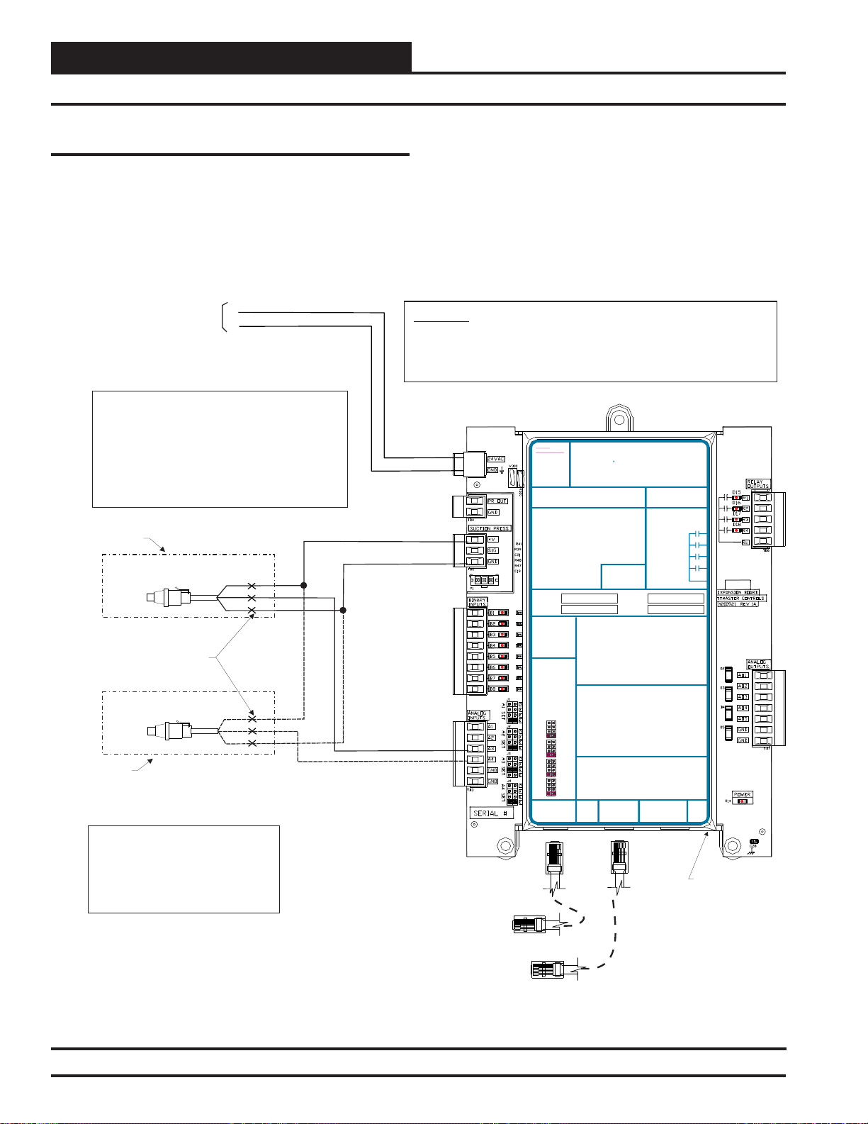
Installation & Wiring
Suction Pressure Transducer Wiring
Zone
Zone
Suction Pressure Transducer
The OE275-01 Suction Pressure Transducer always wires directly to
the Digital Scroll Compressor Controller. See Figure 18 below for
wiring details.
24 VAC
GND
10 VA Minimum Power Required
For SA Expansion Module
Note:
1.) Suction Pressure Transducer(s) Are Only Required
For Installations With The Dehumidification Option
Installed.
2.) Modulating Cooling Output Voltage Must Be
Configured For 1.5 - 5 VDC Operation When You Are
Setting Up The SA Controller Operating Parameters
For A Copeland Digital Compressor.
Wiring For Single
Cabinet Unit
OE275-01
Suction Pressure Transducer
Splice Wire As Required To Reach
From Transducer Location To
Expansion Module Location
OE275-01
Suction Pressure Transducer
Additional Wiring
For Dual Cabinet
Units
Caution:
1.) The Schraeder Port Used For
Installation Of The Suction Pressure
Transducer Should Be Located In A
Vertical Portion Of The Suction Line To
Prevent Refrigerant Oil From
Accumulating In The Sensor.
RD
WH
BK
RD
WH
BK
The Suction Pressure Transducer is used to measure suction pressure
at the HVAC unit’s DX evaporator coil suction line. This suction line
pressure is converted to saturated refrigerant temperature by the SA EBUS Controller. This temperature is used by the SA E-BUS Controller
to accurately control the compressors and reheat cycle components to
provide optimum performance from the system during Dehumidifi ca-
tion operation.
WARNING!!
Observe Polarity! All boards must be wired with GND-to-GND and 24VAC-to-24VAC.
Failure to observe polarity will result in damage to one or more of the boards. Expansion
Module must be wired in such a way that the expansion module and the controller are
always powered together. Loss of power to the expansion module will cause the
controller to become inoperative until power is restored to the expansion module.
24 VAC
POLARITY
WARNING
OBSERVE
Modular Cable
Connect To SA E-BUS
Controller
24 VAC POWER ONLY
POWER ONLY
WARNING!POLARITY MUST BE
WARNING!
OBSERVED OR THE BOARD
POLARITY
WILL BE DAMAGED
MUST BE
OBSERVED OR
THE BOARD
WILL BE
DAMAGED
SA Expansion Module
Orion No.:OE333-23-SA
OE333-23-EM-AVCM-X EXPANSION MODULE
PR OUT
TO VCM-X INPUT
GND
TERMINALS AI5 & GND
SUCTION PRESSURE
+V
TRANSDUCER CONNECTION
SIG
FOR HVAC UNITS WITHOUT
GND
DIGITALCOMPRESSOR
RELAY1 = RELAY3 =
RELAY2 = RELAY4 =
RELAY1 = RELAY3 =
ITIS SUGGESTED
THATYOU WRITE THE
DESCRIPTION OF
RELAY2 = RELAY4 =
THE RELAYOUTPUTS
YOUARE USING IN
ITIS SUGGESTED
THE BOXES
THATYOU WRITE THE
PROVIDEDABOVE
DESCRIPTION OF
WITHA PERMANENT
THE RELAYOUTPUTS
MARKER (SHARPIE®)
YOUARE USING IN
THE BOXES
PROVIDEDABOVE
WITHA PERMANENT
ANALOG INPUT
MARKER (SHARPIE®)
JUMPER SETTINGS
MUST BE SETAS
SHOWN FOR
PROPER
ANALOG INPUT
OPERATION
JUMPER SETTINGS
MUST BE SETAS
SHOWN FOR
PROPER
ANALOG INPUT
OPERATION
JUMPER
SETTINGS
THERM
ANALOG INPUT
4-20mA
JUMPER
AI1
0-10V
SETTINGS
0-5V
THERM
THERM
4-20mA
4-20mA
AI1
AI2
0-10V
0-10V
0-5V
0-5V
THERM
THERM
4-20mA
AI2
4-20mA
0-10V
AI3
0-10V
0-5V
0-5V
THERM
THERM
4-20mA
AI3
4-20mA
0-10V
AI4
0-10V
0-5V
0-5V
THERM
4-20mA
AI4
0-10V
I2C
0-5V
EXPANSION
I2C
WattMaster Label
EXPANSION
BI1 = WATER PROOF OF FLOW -A - N.O. INPUT
= WATER PROOF OF FLOW - B - N.O. INPUT
BI2
= AIR PROOF OF FLOW - N.O. INPUT
BI3
= REMOTE FORCED OCCUPIED - N.O. INPUT
BI4
BI1 = HOOD ON - N.O. INPUT
= EMERGENCY SHUTDOWN - N.C. INPUT
BI5
= DIRTY FILTER - N.O. INPUT
BI2
= DRAIN PAN OVERFLOW -A - N.O. INPUT
BI6
= PROOF OF FLOW - N.O. INPUT
BI3
= DRAIN PAN OVERFLOW - B - N.O. INPUT
BI7
= REMOTE FORCED OCCUPIED - N.O. INPUT
BI4
= DIRTY FILTER - N.O. INPUT
BI8
= REMOTE FORCED HEATING - N.O. INPUT
BI5
BI6
= REMOTE FORCED COOLING - N.O. INPUT
NOTE:
BI7
= SMOKE DETECTOR - N.C. INPUT
ALL BINARY INPUTS MUSTBE 24 VAC ONLY.
BI8
= REMOTE DEHUMIDIFICATION - N.O. INPUT
NOTE:
AO1 = MODULATING HEATING SIGNAL
ALL BINARY INPUTS MUSTBE 24 VAC ONLY.
(0-10 VDC OR 2-10 VDC)
= MODULATING COOLING STAGE 1 SIGNAL
AO2
(0-10 VDC, 2-10 VDC OR 1.5-5 VDC)
AO1 = BUILDING PRESSURE CONTROL VFD OR
= MODULATING COOLING STAGE 2 SIGNAL
AO3
DAMPER ACTUATOR (0-10 OR 2-10 VDC)
(DIGITALCOMPRESSOR ONLY 1.5-5 VDC)
= MODULATING HEATING SIGNAL
AO2
= WSE BYPASS 2ASIGNAL
AO4
(0-10 VDC OR 2-10 VDC)
(0-10 VDC)
= MODULATING COOLING/DIGITALSCROLL
AO3
= WSE BYPASS 2B SIGNAL
AO5
SIGNAL (0-10 VDC, 2-10 VDC OR 1.5-5 VDC)
(0-10 VDC)
= RETURN AIR DAMPERACTUATOR
AO4
= GROUND FOR ANALOG OUTPUTS
GND
(0-10 VDC)
= GROUND FOR ANALOG OUTPUTS
GND
= RETURN AIR BYPASS DAMPERACTUATOR
AO5
(0-10 VDC)
= GROUND FOR ANALOG OUTPUTS
GND
AI1 = ENTERING AIR RH SENSOR (0-5 VDC)
= GROUND FOR ANALOG OUTPUTS
GND
AI2
= INDOOR AIR RH SENSOR (0-5 VDC)
AI3
= SUCTION PRESSURE A(0-5 VDC)
AI4
= SUCTION PRESSURE B (0-5 VDC)
AI1 = OUTDOOR AIR RH SENSOR (0-5 VDC)
GND
= GROUND FOR ANALOG INPUTS
AI2
= INDOOR AIR RH SENSOR (0-5 VDC)
GND
= GROUND FOR ANALOG INPUTS
AI3
= CO2 (0-10 VDC)
AI4
= BUILDING STATIC PRESSURE (0-5 VDC)
GND
= GROUND FOR ANALOG INPUTS
GND
= GROUND FOR ANALOG INPUTS
I2C
EXPANSION
EXPANSION
#LB102034-01
AAON No.:
R96180
www.orioncontrols.com
RELAYCONTACT
RATING IS 1AMP
MAX @ 24 VAC
RELAYCONTACT
RATING IS 1AMP
RELAY1
MAX @ 24 VAC
RELAY2
RELAY1
RELAY3
RELAY2
RELAY4
RELAY3
RELAY
RELAY4
COMMON
RELAY
COMMON
WattMaster Label
#LB102061-A
Rev.: 1C
I2C
SA
SA Expansion
Module
Figure 18: OE275-01 – Suction Pressure Transducer Wiring
22
SA E-BUS Controller Technical Guide
Modular Cable
Connect To Expansion
Module (When Used)
Page 23
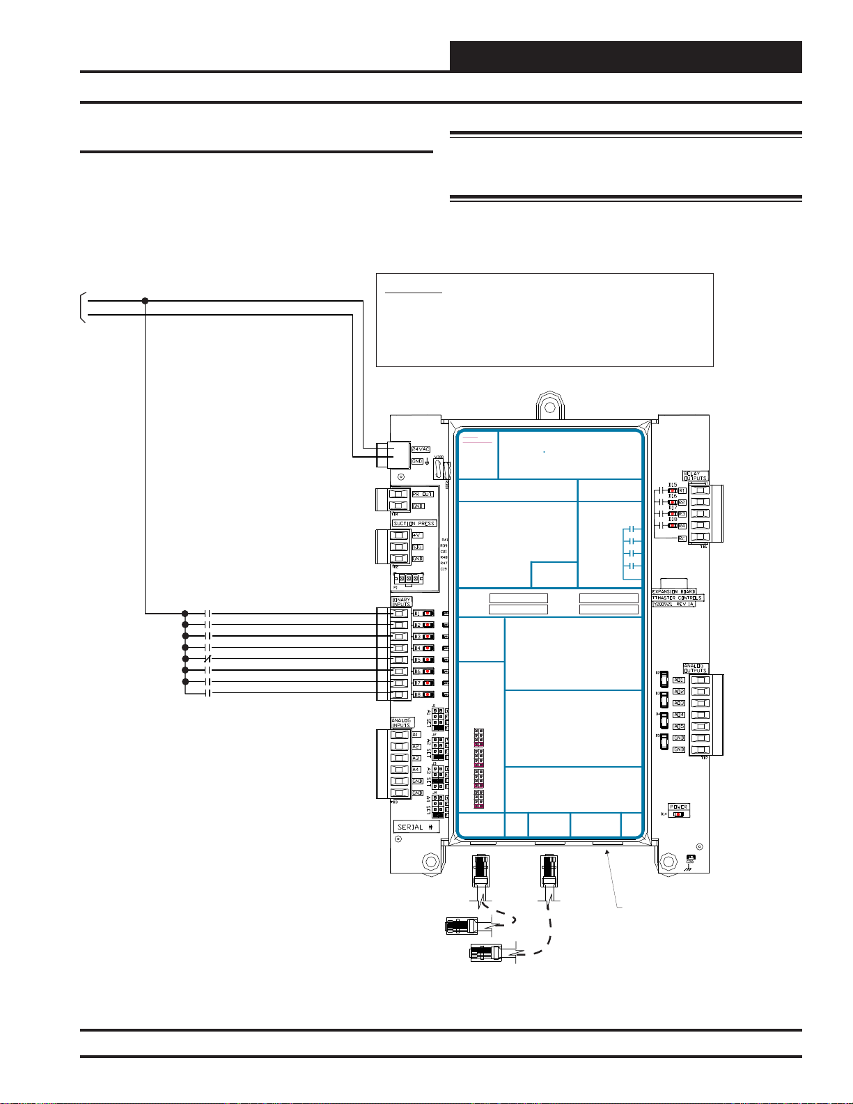
Installation & Wiring
SA Expansion Module Binary Inputs Wiring
SA Expansion Module Binary Inputs
The SA Expansion Module provides 8 Binary Inputs. See Figure 19
below for detailed wiring.
The transformer used for powering the SA Expansion Module must also
be used to power the binary inputs.
10 VA Minimum Power Required
For SA Expansion Module
24 VAC
GND
Water Proof of Flow A - N.O. Input
Water Proof of Flow B - N.O. Input
Air Proof Of Flow - N.O. Input
Remote Forced Occupied-N.O. Input
Emergency Shutdown - N.C. Input
Drain Pan Overflow A - N.O. Input
Drain Pan Overflow B - N.O. Input
Dirty Filter - N.O. Input
WARNING!!
Observe Polarity! All boards must be wired with GND-to-GND and 24VAC-to24VAC. Failure to observe polarity will result in damage to one or more of the
boards. Expansion Module must be wired in such a way that the expansion
module and the controller are always powered together. Loss of power to the
expansion module will cause the controller to become inoperative until power
is restored to the expansion module.
POLARITY
WARNING
OBSERVE
BI1
BI2
BI3
BI4
BI5
BI6
BI7
BI8
Warning: Do not apply any voltage greater than 24 VAC to the
binary inputs. Higher voltages will damage the expansion module
and possibly other components on the system.
24 VAC
24 VAC POWER ONLY
POWER ONLY
WARNING!POLARITY MUST BE
WARNING!
OBSERVED OR THE BOARD
POLARITY
WILL BE DAMAGED
MUST BE
OBSERVED OR
THE BOARD
WILL BE
DAMAGED
SA Expansion Module
Orion No.:OE333-23-SA
OE333-23-EM-A VCM-X EXPANSION MODULE
PR OUT
TO VCM-X INPUT
GND
TERMINALS AI5 & GND
SUCTION PRESSURE
+V
TRANSDUCER CONNECTION
SIG
FOR HVAC UNITS WITHOUT
GND
DIGITALCOMPRESSOR
RELAY 1 = RELAY 3 =
RELAY 2 = RELAY 4 =
RELAY1 = RELAY3 =
IT IS SUGGESTED
THATYOU WRITE THE
DESCRIPTION OF
RELAY2 = RELAY4 =
THE RELAYOUTPUTS
YOUARE USING IN
IT IS SUGGESTED
THE BOXES
THATYOU WRITE THE
PROVIDEDABOVE
DESCRIPTION OF
WITHA PERMANENT
THE RELAYOUTPUTS
MARKER (SHARPIE®)
YOUARE USING IN
THE BOXES
PROVIDEDABOVE
WITHA PERMANENT
ANALOG INPUT
MARKER (SHARPIE®)
JUMPER SETTINGS
MUST BE SETAS
SHOWN FOR
PROPER
ANALOG INPUT
OPERATION
JUMPER SETTINGS
MUST BE SETAS
SHOWN FOR
PROPER
ANALOG INPUT
OPERATION
JUMPER
SETTINGS
THERM
ANALOG INPUT
4-20mA
JUMPER
AI1
0-10V
SETTINGS
0-5V
THERM
THERM
4-20mA
4-20mA
AI1
AI2
0-10V
0-10V
0-5V
0-5V
THERM
THERM
4-20mA
AI2
4-20mA
0-10V
AI3
0-10V
0-5V
0-5V
THERM
THERM
4-20mA
AI3
4-20mA
0-10V
AI4
0-10V
0-5V
0-5V
THERM
4-20mA
AI4
0-10V
I2C
0-5V
EXPANSION
I2C
WattMaster Label
EXPANSION
BI1 = WATER PROOF OF FLOW -A - N.O. INPUT
= WATER PROOF OF FLOW - B - N.O. INPUT
BI2
= AIR PROOF OF FLOW - N.O. INPUT
BI3
= REMOTE FORCED OCCUPIED - N.O. INPUT
BI4
BI1 = HOOD ON - N.O. INPUT
= EMERGENCY SHUTDOWN - N.C. INPUT
BI5
= DIRTY FILTER - N.O. INPUT
BI2
= DRAIN PAN OVERFLOW -A - N.O. INPUT
BI6
= PROOF OF FLOW - N.O. INPUT
BI3
= DRAIN PAN OVERFLOW - B - N.O. INPUT
BI7
= REMOTE FORCED OCCUPIED - N.O. INPUT
BI4
= DIRTY FILTER - N.O. INPUT
BI8
= REMOTE FORCED HEATING - N.O. INPUT
BI5
= REMOTE FORCED COOLING - N.O. INPUT
BI6
NOTE:
BI7
= SMOKE DETECTOR - N.C. INPUT
ALL BINARY INPUTS MUST BE 24 VAC ONLY.
BI8
= REMOTE DEHUMIDIFICATION - N.O. INPUT
NOTE:
AO1 = MODULATING HEATING SIGNAL
ALL BINARY INPUTS MUSTBE 24 VAC ONLY.
(0-10 VDC OR 2-10 VDC)
AO2
= MODULATING COOLING STAGE 1 SIGNAL
(0-10 VDC, 2-10 VDC OR 1.5-5 VDC)
AO1 = BUILDING PRESSURE CONTROL VFD OR
AO3
= MODULATING COOLING STAGE 2 SIGNAL
DAMPER ACTUATOR (0-10 OR 2-10 VDC)
(DIGITALCOMPRESSOR ONLY 1.5-5 VDC)
= MODULATING HEATING SIGNAL
AO2
AO4
= WSE BYPASS 2ASIGNAL
(0-10 VDC OR 2-10 VDC)
(0-10 VDC)
= MODULATING COOLING/DIGITALSCROLL
AO3
= WSE BYPASS 2B SIGNAL
AO5
SIGNAL (0-10 VDC, 2-10 VDC OR 1.5-5 VDC)
(0-10 VDC)
= RETURN AIR DAMPERACTUATOR
AO4
= GROUND FOR ANALOG OUTPUTS
GND
(0-10 VDC)
= GROUND FOR ANALOG OUTPUTS
GND
= RETURN AIR BYPASS DAMPERACTUATOR
AO5
(0-10 VDC)
= GROUND FOR ANALOG OUTPUTS
GND
AI1 = ENTERING AIR RH SENSOR (0-5 VDC)
= GROUND FOR ANALOG OUTPUTS
GND
= INDOOR AIR RH SENSOR (0-5 VDC)
AI2
= SUCTION PRESSURE A(0-5 VDC)
AI3
= SUCTION PRESSURE B (0-5 VDC)
AI4
AI1 = OUTDOOR AIR RH SENSOR (0-5 VDC)
= GROUND FOR ANALOG INPUTS
GND
AI2
= INDOOR AIR RH SENSOR (0-5 VDC)
= GROUND FOR ANALOG INPUTS
GND
AI3
= CO2 (0-10 VDC)
AI4
= BUILDING STATIC PRESSURE (0-5 VDC)
GND
= GROUND FOR ANALOG INPUTS
GND
= GROUND FOR ANALOG INPUTS
I2C
EXPANSION
EXPANSION
#LB102034-01
AAON No.:
R96180
www.orioncontrols.com
RELAY CONTACT
RATING IS 1AMP
MAX @ 24 VAC
RELAYCONTACT
RATING IS 1AMP
RELAY 1
MAX @ 24 VAC
RELAY 2
RELAY1
RELAY 3
RELAY2
RELAY 4
RELAY3
RELAY
RELAY4
COMMON
RELAY
COMMON
WattMaster Label
#LB102061-A
Rev.: 1C
I2C
SA
Modular Cable
Connect To SA E-BUS
Controller
Modular Cable Connect To
Expansion Module
(When Used)
Figure 19: OE333-23-SA – SA Expansion Module 8 Binary Inputs Wiring
SA E-BUS Controller Technical Guide
SA Expansion
Module
23
Page 24

Installation & Wiring
Entering Air Humidity Sensor Wiring
Zone
Zone
Entering Air Humidity Sensor
The OE265-14 Entering Air Humidity Sensor is connected to the system
by wiring it to the AI1 input on the SA Expansion Module. It must be
wired as shown in Figure 20 below for proper controller operation.
24 VAC
GND
10 VA Minimum Power
Required For
SA Expansion Module
Entering Air Humidity Sensor
Span
VAC or DC
GND
44556
3
2
Zero
0-5V or 0-10V
1
ON
Jumpers Must Be Set
as Shown For Normal
Operation Of Sensor
1, 2, 4, 5 & 6 Are Off
6
3 Is On
3
2
Jumper
1
ON
Must
Be Set To
0-5V As
Shown
4
3
2
1
ON
Note: No Additional
Wiring is Required For
Dual Cabinet Units.
4-20 mA
4ON321
Jumpers Must Be
Set as Shown For
Correct
O-5 VDC Operation
1 & 3 Are Off
2 & 4 Are On
Warning: It is very important to be certain that all wiring is
correct as shown in the wiring diagram below. Failure to observe the
correct polarity will result in damage to the Entering Air Humidity
Sensor or SA Expansion Module.
WARNING!!
Observe Polarity! All boards must be wired with GND-to-GND and
24VAC-to-24VAC. Failure to observe polarity will result in damage to
one or more of the boards. Expansion Module must be wired in such
a way that the expansion module and the controller are always
powered together. Loss of power to the expansion module will cause
the controller to become inoperative until power is restored to the
expansion module.
24 VAC
POLARITY
WARNING
OBSERVE
AI1
GND
Modular Cable
Connect To SA E-BUS
Controller
24 VAC POWER ONLY
POWER ONLY
WARNING!POLARITY MUST BE
WARNING!
OBSERVED OR THE BOARD
POLARITY
WILL BE DAMAGED
MUST BE
OBSERVED OR
THE BOARD
WILL BE
DAMAGED
SA Expansion Module
Orion No.:OE333-23-SA
OE333-23-EM-A VCM-X EXPANSION MODULE
PR OUT
TO VCM-X INPUT
GND
TERMINALS AI5 & GND
SUCTION PRESSURE
+V
TRANSDUCER CONNECTION
SIG
FOR HVAC UNITS WITHOUT
GND
DIGITALCOMPRESSOR
RELAY1 = RELAY 3 =
RELAY2 = RELAY 4 =
RELAY1 = RELAY3 =
IT IS SUGGESTED
THATYOU WRITE THE
DESCRIPTION OF
RELAY2 = RELAY4 =
THE RELAYOUTPUTS
YOUARE USING IN
IT IS SUGGESTED
THE BOXES
THATYOU WRITE THE
PROVIDEDABOVE
DESCRIPTION OF
WITHA PERMANENT
THE RELAYOUTPUTS
MARKER (SHARPIE®)
YOUARE USING IN
THE BOXES
PROVIDEDABOVE
WITHA PERMANENT
ANALOG INPUT
MARKER (SHARPIE®)
JUMPER SETTINGS
MUST BE SETAS
SHOWN FOR
PROPER
ANALOG INPUT
OPERATION
JUMPER SETTINGS
MUST BE SETAS
SHOWN FOR
PROPER
ANALOG INPUT
OPERATION
JUMPER
SETTINGS
THERM
ANALOG INPUT
4-20mA
JUMPER
AI1
0-10V
SETTINGS
0-5V
THERM
THERM
4-20mA
4-20mA
AI1
AI2
0-10V
0-10V
0-5V
0-5V
THERM
THERM
4-20mA
AI2
4-20mA
0-10V
AI3
0-10V
0-5V
0-5V
THERM
THERM
4-20mA
AI3
4-20mA
0-10V
AI4
0-10V
0-5V
0-5V
THERM
4-20mA
AI4
0-10V
I2C
0-5V
EXPANSION
I2C
WattMaster Label
EXPANSION
BI1 = WATER PROOF OF FLOW -A - N.O. INPUT
BI2
= WATER PROOF OF FLOW - B - N.O. INPUT
BI3
= AIR PROOF OF FLOW - N.O. INPUT
BI4
= REMOTE FORCED OCCUPIED - N.O. INPUT
BI1 = HOOD ON - N.O. INPUT
BI5
= EMERGENCY SHUTDOWN - N.C. INPUT
= DIRTY FILTER - N.O. INPUT
BI2
BI6
= DRAIN PAN OVERFLOW -A - N.O. INPUT
= PROOF OF FLOW - N.O. INPUT
BI3
BI7
= DRAIN PAN OVERFLOW - B - N.O. INPUT
= REMOTE FORCED OCCUPIED - N.O. INPUT
BI4
BI8
= DIRTY FILTER - N.O. INPUT
= REMOTE FORCED HEATING - N.O. INPUT
BI5
= REMOTE FORCED COOLING - N.O. INPUT
BI6
NOTE:
= SMOKE DETECTOR - N.C. INPUT
BI7
ALL BINARY INPUTS MUSTBE 24 VAC ONLY.
BI8
= REMOTE DEHUMIDIFICATION - N.O. INPUT
NOTE:
AO1 = MODULATING HEATING SIGNAL
ALL BINARY INPUTS MUSTBE 24 VAC ONLY.
(0-10 VDC OR 2-10 VDC)
= MODULATING COOLING STAGE 1 SIGNAL
AO2
(0-10 VDC, 2-10 VDC OR 1.5-5 VDC)
AO1 = BUILDING PRESSURE CONTROL VFD OR
= MODULATING COOLING STAGE 2 SIGNAL
AO3
DAMPER ACTUATOR (0-10 OR 2-10 VDC)
(DIGITALCOMPRESSOR ONLY 1.5-5 VDC)
AO2
= MODULATING HEATING SIGNAL
= WSE BYPASS 2ASIGNAL
AO4
(0-10 VDC OR 2-10 VDC)
(0-10 VDC)
AO3
= MODULATING COOLING/DIGITALSCROLL
= WSE BYPASS 2B SIGNAL
AO5
SIGNAL (0-10 VDC, 2-10 VDC OR 1.5-5 VDC)
(0-10 VDC)
AO4
= RETURN AIR DAMPERACTUATOR
= GROUND FOR ANALOG OUTPUTS
GND
(0-10 VDC)
= GROUND FOR ANALOG OUTPUTS
GND
AO5
= RETURN AIR BYPASS DAMPERACTUATOR
(0-10 VDC)
GND
= GROUND FOR ANALOG OUTPUTS
AI1 = ENTERING AIR RH SENSOR (0-5 VDC)
GND
= GROUND FOR ANALOG OUTPUTS
AI2
= INDOOR AIR RH SENSOR (0-5 VDC)
AI3
= SUCTION PRESSURE A(0-5 VDC)
AI4
= SUCTION PRESSURE B (0-5 VDC)
AI1 = OUTDOOR AIR RH SENSOR (0-5 VDC)
GND
= GROUND FOR ANALOG INPUTS
AI2
= INDOOR AIR RH SENSOR (0-5 VDC)
GND
= GROUND FOR ANALOG INPUTS
AI3
= CO2 (0-10 VDC)
AI4
= BUILDING STATIC PRESSURE (0-5 VDC)
GND
= GROUND FOR ANALOG INPUTS
GND
= GROUND FOR ANALOG INPUTS
I2C
EXPANSION
EXPANSION
#LB102034-01
AAON No.:
R96180
www.orioncontrols.com
RELAYCONTACT
RATING IS 1AMP
MAX @ 24 VAC
RELAYCONTACT
RATING IS 1AMP
RELAY1
MAX @ 24 VAC
RELAY2
RELAY1
RELAY3
RELAY2
RELAY4
RELAY3
RELAY
RELAY4
COMMON
RELAY
COMMON
WattMaster Label
#LB102061-A
Rev.: 1C
SA Expansion
Module
I2C
SA
Modular Cable
Connect To Expansion Module
(When Used)
Figure 20: OE265-14 – Entering Air Humidity Sensor Wiring
24
SA E-BUS Controller Technical Guide
Page 25

Installation & Wiring
Indoor Wall-Mounted Humidity Sensor Wiring
Indoor Wall-Mounted Humidity Sensor
When used, the OE265-11 Indoor Wall-Mounted Humidity Sensor is
connected to the system by wiring it to the AI2 input on the SA Expansion Module. It must be wired as shown in Figure 21 below for proper
controller operation.
24 VAC
GND
10 VA Minimum Power Required
For SA Expansion Module
Space Humidity Sensor
Zero
Span
4
3
2
1
Io
Vo
Gnd
Vin
Note: No Additional
Wiring is Required For
Dual Cabinet Units.
ON
44556
3
2
1
ON
6
Jumpers Must Be
Set as Shown For
Normal
Operation Of
Sensor
1, 2, 4, 5 & 6 Are Off
3 Is On
4
3
2
1
ON
Jumpers Must Be
Set as Shown
For Correct
ON
O-5 VDC
Operation
1 & 3 Are Off
2 & 4 Are On
Jumper Must
Be Set To
0-5V As
Shown
3
2
1
Warning: It is very important to be certain that all wiring is
correct as shown in the wiring diagram below. Failure to observe
the correct polarity will result in damage to the Space Humidity
Sensor or SA Expansion Module.
WARNING!!
Observe Polarity! All boards must be wired with GND-to-GND and
24VAC-to-24VAC. Failure to observe polarity will result in damage to
one or more of the boards. Expansion Module must be wired in such a
way that the expansion module and the controller are always powered
together. Loss of power to the expansion module will cause the
controller to become inoperative until power is restored to the
expansion module.
24 VAC
POLARITY
WARNING
OBSERVE
AI2
GND
Modular Cable
Connect To SA E-BUS
Controller
24 VAC POWER ONLY
POWER ONLY
WARNING!POLARITY MUST BE
WARNING!
OBSERVED OR THE BOARD
POLARITY
WILL BE DAMAGED
MUST BE
OBSERVED OR
THE BOARD
WILL BE
DAMAGED
SA Expansion Module
Orion No.:OE333-23-SA
OE333-23-EM-A VCM-X EXPANSION MODULE
PR OUT
TO VCM-X INPUT
GND
TERMINALS AI5 & GND
SUCTION PRESSURE
+V
TRANSDUCER CONNECTION
SIG
FOR HVAC UNITS WITHOUT
GND
DIGITALCOMPRESSOR
RELAY1 = RELAY 3 =
RELAY2 = RELAY 4 =
RELAY1 = RELAY 3 =
IT IS SUGGESTED
THATYOU WRITE THE
DESCRIPTION OF
RELAY2 = RELAY 4 =
THE RELAYOUTPUTS
YOUARE USING IN
IT IS SUGGESTED
THE BOXES
THATYOU WRITE THE
PROVIDEDABOVE
DESCRIPTION OF
WITHA PERMANENT
THE RELAYOUTPUTS
MARKER (SHARPIE®)
YOUARE USING IN
THE BOXES
PROVIDEDABOVE
WITHA PERMANENT
ANALOG INPUT
MARKER (SHARPIE®)
JUMPER SETTINGS
MUST BE SETAS
SHOWN FOR
PROPER
ANALOG INPUT
OPERATION
JUMPER SETTINGS
MUST BE SETAS
SHOWN FOR
PROPER
ANALOG INPUT
OPERATION
JUMPER
SETTINGS
THERM
ANALOG INPUT
4-20mA
JUMPER
AI1
0-10V
SETTINGS
0-5V
THERM
THERM
4-20mA
4-20mA
AI1
AI2
0-10V
0-10V
0-5V
0-5V
THERM
THERM
4-20mA
AI2
4-20mA
0-10V
AI3
0-10V
0-5V
0-5V
THERM
THERM
4-20mA
AI3
4-20mA
0-10V
AI4
0-10V
0-5V
0-5V
THERM
4-20mA
AI4
0-10V
I2C
0-5V
EXPANSION
I2C
WattMaster Label
EXPANSION
BI1 = WATER PROOF OF FLOW -A - N.O. INPUT
BI2
= WATER PROOF OF FLOW - B - N.O. INPUT
BI3
= AIR PROOF OF FLOW - N.O. INPUT
BI4
= REMOTE FORCED OCCUPIED - N.O. INPUT
BI1 = HOOD ON - N.O. INPUT
BI5
= EMERGENCY SHUTDOWN - N.C. INPUT
= DIRTY FILTER - N.O. INPUT
BI2
BI6
= DRAIN PAN OVERFLOW -A - N.O. INPUT
= PROOF OF FLOW - N.O. INPUT
BI3
BI7
= DRAIN PAN OVERFLOW - B - N.O. INPUT
= REMOTE FORCED OCCUPIED - N.O. INPUT
BI4
BI8
= DIRTY FILTER - N.O. INPUT
= REMOTE FORCED HEATING - N.O. INPUT
BI5
BI6
= REMOTE FORCED COOLING - N.O. INPUT
NOTE:
BI7
= SMOKE DETECTOR - N.C. INPUT
ALL BINARY INPUTS MUSTBE 24 VAC ONLY.
BI8
= REMOTE DEHUMIDIFICATION - N.O. INPUT
NOTE:
AO1 = MODULATING HEATING SIGNAL
ALL BINARY INPUTS MUSTBE 24 VAC ONLY.
(0-10 VDC OR 2-10 VDC)
AO2
= MODULATING COOLING STAGE 1 SIGNAL
(0-10 VDC, 2-10 VDC OR 1.5-5 VDC)
AO1 = BUILDING PRESSURE CONTROL VFD OR
AO3
= MODULATING COOLING STAGE 2 SIGNAL
DAMPER ACTUATOR (0-10 OR 2-10 VDC)
(DIGITALCOMPRESSOR ONLY 1.5-5 VDC)
= MODULATING HEATING SIGNAL
AO2
AO4
= WSE BYPASS 2ASIGNAL
(0-10 VDC OR 2-10 VDC)
(0-10 VDC)
= MODULATING COOLING/DIGITALSCROLL
AO3
AO5
= WSE BYPASS 2B SIGNAL
SIGNAL (0-10 VDC, 2-10 VDC OR 1.5-5 VDC)
(0-10 VDC)
= RETURN AIR DAMPERACTUATOR
AO4
GND
= GROUND FOR ANALOG OUTPUTS
(0-10 VDC)
GND
= GROUND FOR ANALOG OUTPUTS
= RETURN AIR BYPASS DAMPERACTUATOR
AO5
(0-10 VDC)
= GROUND FOR ANALOG OUTPUTS
GND
AI1 = ENTERING AIR RH SENSOR (0-5 VDC)
= GROUND FOR ANALOG OUTPUTS
GND
AI2
= INDOOR AIR RH SENSOR (0-5 VDC)
AI3
= SUCTION PRESSURE A(0-5 VDC)
AI4
= SUCTION PRESSURE B (0-5 VDC)
AI1 = OUTDOOR AIR RH SENSOR (0-5 VDC)
GND
= GROUND FOR ANALOG INPUTS
AI2
= INDOOR AIR RH SENSOR (0-5 VDC)
GND
= GROUND FOR ANALOG INPUTS
AI3
= CO2 (0-10 VDC)
AI4
= BUILDING STATIC PRESSURE (0-5 VDC)
GND
= GROUND FOR ANALOG INPUTS
GND
= GROUND FOR ANALOG INPUTS
I2C
EXPANSION
EXPANSION
#LB102034-01
AAON No.:
R96180
www.orioncontrols.com
RELAYCONTACT
RATING IS 1AMP
MAX @ 24 VAC
RELAYCONTACT
RATING IS 1AMP
RELAY1
MAX @ 24 VAC
RELAY2
RELAY1
RELAY3
RELAY2
RELAY4
RELAY3
RELAY
RELAY4
COMMON
RELAY
COMMON
WattMaster Label
#LB102061-A
Rev.: 1C
SA Expansion
Module
I2C
SA
Modular Cable
Connect To Expansion
Module (When Used)
Figure 21: OE265-11 – Indoor Wall-Mounted Humidity Sensor Wiring
SA E-BUS Controller Technical Guide
25
Page 26

Installation & Wiring
Modulating Heating Device Wiring
Zone
Zone
Modulating Heating Device
The Modulating Heating Device signal can be confi gured for either a
0-10 VDC or 2-10 VDC output signal when programming the controller .
The output signal can be confi gured for either Direct Acting or Reverse
Acting operation as required.
The Output signal is normally used to control a Modulating Hot Water
Valve or Modulating Steam Valve or is used for SCR Control of an
Electric Heating Coil.
WARNING!!
Observe Polarity! All boards must be wired with GND-to-GND and 24VAC-to24VAC. Failure to observe polarity will result in damage to one or more of the
boards. Expansion Module must be wired in such a way that the expansion
module and the controller are always powered together. Loss of power to the
expansion module will cause the controller to become inoperative until power is
restored to the expansion module.
24 VAC
24 VAC POWER ONLY
POWER ONLY
WARNING!POLARITY MUST BE
WARNING!
OBSERVED OR THE BOARD
POLARITY
WILL BE DAMAGED
MUST BE
OBSERVED OR
POLARITY
WARNING
OBSERVE
THE BOARD
WILL BE
DAMAGED
SA Expansion Module
Orion No.:OE333-23-SA
OE333-23-EM-AVCM-X EXPANSION MODULE
PR OUT
TO VCM-X INPUT
GND
TERMINALS AI5 & GND
SUCTION PRESSURE
+V
TRANSDUCER CONNECTION
SIG
FOR HVAC UNITS WITHOUT
GND
DIGITALCOMPRESSOR
RELAY1 = RELAY3 =
RELAY2 = RELAY4 =
RELAY1 = RELAY3 =
ITIS SUGGESTED
THATYOU WRITE THE
DESCRIPTION OF
RELAY2 = RELAY4 =
THE RELAYOUTPUTS
YOUARE USING IN
ITIS SUGGESTED
THE BOXES
THATYOU WRITE THE
PROVIDEDABOVE
DESCRIPTION OF
WITHA PERMANENT
THE RELAYOUTPUTS
MARKER (SHARPIE®)
YOUARE USING IN
THE BOXES
PROVIDEDABOVE
WITHA PERMANENT
ANALOG INPUT
MARKER (SHARPIE®)
JUMPER SETTINGS
MUST BE SETAS
SHOWN FOR
PROPER
ANALOG INPUT
OPERATION
JUMPER SETTINGS
MUST BE SETAS
SHOWN FOR
PROPER
ANALOG INPUT
OPERATION
JUMPER
SETTINGS
THERM
ANALOG INPUT
4-20mA
JUMPER
AI1
0-10V
SETTINGS
0-5V
THERM
THERM
4-20mA
4-20mA
AI1
AI2
0-10V
0-10V
0-5V
0-5V
THERM
THERM
4-20mA
AI2
4-20mA
0-10V
AI3
0-10V
0-5V
0-5V
THERM
THERM
4-20mA
AI3
4-20mA
0-10V
AI4
0-10V
0-5V
0-5V
THERM
4-20mA
AI4
0-10V
I2C
0-5V
EXPANSION
I2C
WattMaster Label
EXPANSION
BI1 = WATER PROOF OF FLOW -A - N.O. INPUT
= WATER PROOF OF FLOW - B - N.O. INPUT
BI2
= AIR PROOF OF FLOW - N.O. INPUT
BI3
= REMOTE FORCED OCCUPIED - N.O. INPUT
BI4
BI1 = HOOD ON - N.O. INPUT
= EMERGENCY SHUTDOWN - N.C. INPUT
BI5
= DIRTY FILTER - N.O. INPUT
BI2
= DRAIN PAN OVERFLOW -A - N.O. INPUT
BI6
= PROOF OF FLOW - N.O. INPUT
BI3
= DRAIN PAN OVERFLOW - B - N.O. INPUT
BI7
= REMOTE FORCED OCCUPIED - N.O. INPUT
BI4
= DIRTY FILTER - N.O. INPUT
BI8
= REMOTE FORCED HEATING - N.O. INPUT
BI5
BI6
= REMOTE FORCED COOLING - N.O. INPUT
NOTE:
BI7
= SMOKE DETECTOR - N.C. INPUT
ALL BINARY INPUTS MUSTBE 24 VAC ONLY.
BI8
= REMOTE DEHUMIDIFICATION - N.O. INPUT
NOTE:
AO1 = MODULATING HEATING SIGNAL
ALL BINARY INPUTS MUSTBE 24 VAC ONLY.
(0-10 VDC OR 2-10 VDC)
= MODULATING COOLING STAGE 1 SIGNAL
AO2
(0-10 VDC, 2-10 VDC OR 1.5-5 VDC)
AO1 = BUILDING PRESSURE CONTROL VFD OR
= MODULATING COOLING STAGE 2 SIGNAL
AO3
DAMPER ACTUATOR (0-10 OR 2-10 VDC)
(DIGITALCOMPRESSOR ONLY 1.5-5 VDC)
= MODULATING HEATING SIGNAL
AO2
= WSE BYPASS 2ASIGNAL
AO4
(0-10 VDC OR 2-10 VDC)
(0-10 VDC)
= MODULATING COOLING/DIGITALSCROLL
AO3
= WSE BYPASS 2B SIGNAL
AO5
SIGNAL (0-10 VDC, 2-10 VDC OR 1.5-5 VDC)
(0-10 VDC)
= RETURN AIR DAMPERACTUATOR
AO4
= GROUND FOR ANALOG OUTPUTS
GND
(0-10 VDC)
= GROUND FOR ANALOG OUTPUTS
GND
AO5
= RETURN AIR BYPASS DAMPERACTUATOR
(0-10 VDC)
GND
= GROUND FOR ANALOG OUTPUTS
AI1 = ENTERING AIR RH SENSOR (0-5 VDC)
GND
= GROUND FOR ANALOG OUTPUTS
AI2
= INDOOR AIR RH SENSOR (0-5 VDC)
AI3
= SUCTION PRESSURE A(0-5 VDC)
AI4
= SUCTION PRESSURE B (0-5 VDC)
AI1 = OUTDOOR AIR RH SENSOR (0-5 VDC)
GND
= GROUND FOR ANALOG INPUTS
AI2
= INDOOR AIR RH SENSOR (0-5 VDC)
GND
= GROUND FOR ANALOG INPUTS
AI3
= CO2 (0-10 VDC)
AI4
= BUILDING STATIC PRESSURE (0-5 VDC)
GND
= GROUND FOR ANALOG INPUTS
GND
= GROUND FOR ANALOG INPUTS
I2C
EXPANSION
EXPANSION
#LB102034-01
AAON No.:
R96180
www.orioncontrols.com
RELAYCONTACT
RATING IS 1AMP
MAX @ 24 VAC
RELAYCONTACT
RATING IS 1AMP
RELAY1
MAX @ 24 VAC
RELAY2
RELAY1
RELAY3
RELAY2
RELAY4
RELAY3
RELAY
RELAY4
COMMON
RELAY
COMMON
WattMaster Label
#LB102061-A
Rev.: 1C
I2C
See Figure 22 below for detailed wiring of the Modulating Heating
Device.
Warning: It is very important to be certain that all wiring is
correct as shown in the wiring diagram below. Failure to observe the
correct polarity could result in damage to the Modulating Heating
Device or the SA Expansion Module.
24 VAC
GND
SA
(0 To 10 VDC Or 2 To 10 VDC Input)
AO1
GND
10 VA Minimum Power
Required For
SA Expansion Module
Note:
1.) The Modulating
Heating Device Used
On The SA Controller
Must Have (1) Relay
Output Configured
For It In Order To
Enable The
Modulating Heating
Device's Sequence.
This Relay Output
Must Be Configured
When Setting Up The
SA Controller
Operating
Parameters. The
Modulating Heating
Output’s Voltage Can
Also Be Configured
For Either 0 To 10
VDC Or 2 To 10 VDC
In The Configuration
Menu.
Modulating Heating Device
+
_
GND
SA Expansion
Module
Figure 22: Modulating Heating Device Wiring
26
Modular Cable
Connect To SA E-BUS Controller
Modular Cable
Connect To Expansion
Module (When Used)
SA E-BUS Controller Technical Guide
Page 27

Installation & Wiring
Modulating Cooling Device Wiring
Chilled Water Valve
For Chilled Water Applications, the Modulating Cooling Signal(s) can
be confi gured for either a 0-10 VDC or 2-10 VDC output signal when
programming the controller. The output signal can also be confi gured
for either Direct Acting or Reverse Acting operation as required by your
application. This signal output would be connected to a Modulating
Chilled Water Valve.
See Figure 23 below for detailed wiring of a Chilled Water Valve.
WARNING!!
Observe Polarity! All boards must be wired with GND-to-GND and 24VAC-to24VAC. Failure to observe polarity will result in damage to one or more of the
boards. Expansion Module must be wired in such a way that the expansion
module and the controller are always powered together. Loss of power to the
expansion module will cause the controller to become inoperative until power
is restored to the expansion module.
24 VAC
24 VAC POWER ONLY
POWER ONLY
WARNING!POLARITY MUST BE
WARNING!
OBSERVED OR THE BOARD
POLARITY
WILL BE DAMAGED
MUST BE
OBSERVED OR
POLARITY
WARNING
OBSERVE
THE BOARD
WILL BE
DAMAGED
SA Expansion Module
Orion No.:OE333-23-SA
OE333-23-EM-AVCM-X EXPANSION MODULE
PR OUT
TO VCM-X INPUT
GND
TERMINALS AI5 & GND
SUCTION PRESSURE
+V
TRANSDUCER CONNECTION
SIG
FOR HVAC UNITS WITHOUT
GND
DIGITALCOMPRESSOR
RELAY1 = RELAY3 =
RELAY2 = RELAY4 =
RELAY1 = RELAY 3 =
ITIS SUGGESTED
THATYOU WRITE THE
DESCRIPTION OF
RELAY2 = RELAY 4 =
THE RELAYOUTPUTS
YOUARE USING IN
ITIS SUGGESTED
THE BOXES
THATYOU WRITE THE
PROVIDEDABOVE
DESCRIPTION OF
WITHA PERMANENT
THE RELAYOUTPUTS
MARKER (SHARPIE®)
YOUARE USING IN
THE BOXES
PROVIDEDABOVE
WITHA PERMANENT
ANALOG INPUT
MARKER (SHARPIE®)
JUMPER SETTINGS
MUST BE SETAS
SHOWN FOR
PROPER
ANALOG INPUT
OPERATION
JUMPER SETTINGS
MUST BE SETAS
SHOWN FOR
PROPER
ANALOG INPUT
OPERATION
JUMPER
SETTINGS
THERM
ANALOG INPUT
4-20mA
JUMPER
AI1
0-10V
SETTINGS
0-5V
THERM
THERM
4-20mA
4-20mA
AI1
AI2
0-10V
0-10V
0-5V
0-5V
THERM
THERM
4-20mA
AI2
4-20mA
0-10V
AI3
0-10V
0-5V
0-5V
THERM
THERM
4-20mA
AI3
4-20mA
0-10V
AI4
0-10V
0-5V
0-5V
THERM
4-20mA
AI4
0-10V
I2C
0-5V
EXPANSION
I2C
WattMaster Label
EXPANSION
BI1 = WATER PROOF OF FLOW -A - N.O. INPUT
= WATER PROOF OF FLOW - B - N.O. INPUT
BI2
= AIR PROOF OF FLOW - N.O. INPUT
BI3
= REMOTE FORCED OCCUPIED - N.O. INPUT
BI4
BI1 = HOOD ON - N.O. INPUT
= EMERGENCY SHUTDOWN - N.C. INPUT
BI5
= DIRTY FILTER - N.O. INPUT
BI2
= DRAIN PAN OVERFLOW -A - N.O. INPUT
BI6
= PROOF OF FLOW - N.O. INPUT
BI3
= DRAIN PAN OVERFLOW - B - N.O. INPUT
BI7
= REMOTE FORCED OCCUPIED - N.O. INPUT
BI4
= DIRTY FILTER - N.O. INPUT
BI8
= REMOTE FORCED HEATING - N.O. INPUT
BI5
= REMOTE FORCED COOLING - N.O. INPUT
BI6
NOTE:
= SMOKE DETECTOR - N.C. INPUT
BI7
ALL BINARY INPUTS MUSTBE 24 VAC ONLY.
BI8
= REMOTE DEHUMIDIFICATION - N.O. INPUT
NOTE:
AO1 = MODULATING HEATING SIGNAL
ALL BINARYINPUTS MUST BE 24 VAC ONLY.
(0-10 VDC OR 2-10 VDC)
AO2
= MODULATING COOLING STAGE 1 SIGNAL
(0-10 VDC, 2-10 VDC OR 1.5-5 VDC)
AO1 = BUILDING PRESSURE CONTROL VFD OR
AO3
= MODULATING COOLING STAGE 2 SIGNAL
DAMPER ACTUATOR (0-10 OR 2-10 VDC)
(DIGITALCOMPRESSOR ONLY 1.5-5 VDC)
AO2
= MODULATING HEATING SIGNAL
AO4
= WSE BYPASS 2ASIGNAL
(0-10 VDC OR 2-10 VDC)
(0-10 VDC)
AO3
= MODULATING COOLING/DIGITALSCROLL
AO5
= WSE BYPASS 2B SIGNAL
SIGNAL (0-10 VDC, 2-10 VDC OR 1.5-5 VDC)
(0-10 VDC)
AO4
= RETURN AIR DAMPERACTUATOR
GND
= GROUND FOR ANALOG OUTPUTS
(0-10 VDC)
GND
= GROUND FOR ANALOG OUTPUTS
AO5
= RETURN AIR BYPASS DAMPERACTUATOR
(0-10 VDC)
= GROUND FOR ANALOG OUTPUTS
GND
AI1 = ENTERING AIR RH SENSOR (0-5 VDC)
= GROUND FOR ANALOG OUTPUTS
GND
AI2
= INDOOR AIR RH SENSOR (0-5 VDC)
AI3
= SUCTION PRESSURE A(0-5 VDC)
AI4
= SUCTION PRESSURE B (0-5 VDC)
AI1 = OUTDOOR AIR RH SENSOR (0-5 VDC)
GND
= GROUND FOR ANALOG INPUTS
AI2
= INDOOR AIR RH SENSOR (0-5 VDC)
GND
= GROUND FOR ANALOG INPUTS
AI3
= CO2 (0-10 VDC)
AI4
= BUILDING STATIC PRESSURE (0-5 VDC)
GND
= GROUND FOR ANALOG INPUTS
GND
= GROUND FOR ANALOG INPUTS
I2C
EXPANSION
EXPANSION
#LB102034-01
AAON No.:
R96180
www.orioncontrols.com
RELAYCONTACT
RATING IS 1AMP
MAX @ 24 VAC
RELAYCONTACT
RATING IS 1AMP
RELAY1
MAX @ 24 VAC
RELAY2
RELAY1
RELAY3
RELAY2
RELAY4
RELAY3
RELAY
RELAY4
COMMON
RELAY
COMMON
WattMaster Label
#LB102061-A
Rev.: 1C
I2C
Warning: It is very important to be certain that all wiring is
correct as shown in the wiring diagram below. Failure to observe the
correct polarity could result in damage to the Modulating Cooling
Device or the SA Expansion Module.
24 VAC
GND
Note:
1.) For Chilled Water Applications,
the Modulating Cooling Device Used
Must Be Capable Of Accepting
Either A 0-10 VDC or 2-10 VDC
Input. The Modulating Cooling
Output Voltage Is User-Configurable
For These Voltages. This Voltage
Output Must Be Configured When
You Are Setting Up The SA
Controller’(s) Operating Parameters.
2.) The Modulating Cooling Device
Used On The SA Controller Must
Have (1) Relay Output Configured
In Order To Enable The Modulating
Cooling Device's Sequence. This
Relay Output Must Be Configured
When Setting Up The SA Controller
Operating Parameters.
SA
Modulating Cooling Stage 1
(0 To 10 Or 2 To 10 VDC Input)
AO2
10 VA Minimum Power
Required
For SA Expansion Module
Chilled Water Valve
+
COM
SA Expansion
Module
Connect To SA E-BUS Controller
Modular Cable
Connect To Expansion
Module (When Used)
Modular Cable
Figure 23: Chilled Water Valve Wiring
SA E-BUS Controller Technical Guide
27
Page 28

Installation & Wiring
Modulating Cooling Device Wiring
Zone
Zone
Digital Scroll Compressor Wiring
For Digital Scroll Applications, the Modulating Cooling Signal(s) must
be confi gured for a 1.5-5.0 VDC output signal when programming the
controller. This signal output would be connected to a Digital Scroll
Compressor Controller.
Caution:
1.) The Schraeder Port Used For Installation
Of The Suction Pressure Transducer Should
Be Located In A Vertical Portion Of The
Suction Line To Prevent Refrigerant Oil From
Accumulating In The Sensor.
Note:
1.) Suction Pressure Transducer(s) Are Only Required For
Installations With The Dehumidification Option Installed.
Wiring For Single
Cabinet Unit
For Digital Scroll Compressor wiring details, see Figure 24 below.
24 VAC
10 VA Minimum Power
Required
For SA Expansion Module
Suction Pressure Transducer
OE275-01
RD
WH
BK
GND
Splice Wire As Required To
Reach From Transducer
Location To Expansion Module
Location
Additional Wiring
For Dual Cabinet
Units
Suction Pressure Transducer
OE275-01
RD
WH
BK
WARNING!!
Observe Polarity! All boards must be wired with GND-to-GND and 24VAC-to24VAC. Failure to observe polarity will result in damage to one or more of
the boards. Expansion Module must be wired in such a way that the
expansion module and the controller are always powered together. Loss of
power to the expansion module will cause the controller to become
inoperative until power is restored to the expansion module.
Figure 24: Digital Scroll Compressor Wiring
28
SA E-BUS Controller Technical Guide
Page 29

24VAC
GND
+V
GND
A 3I
AI4
Warning: It is very important to be certain that all wiring is
correct as shown in the wiring diagram below. Failure to observe the
correct polarity could result in damage to the Modulating Cooling
Device or the SA Expansion Module.
24 VAC
24 VAC POWER ONLY
POWER ONLY
WARNING! POLARITY MUST BE
WARNING!
OBSERVED OR THE BOARD
POLARITY
WILL BE DAMAGED
MUST BE
OBSERVED OR
POLARITY
WARNING
OBSERVE
THE BOARD
WILL BE
DAMAGED
SA Expansion Module
Orion No.:OE333-23-SA
OE333-23-EM-A VCM-X EXPANSION MODULE
PR OUT
TO VCM-X INPUT
GND
TERMINALS AI5 & GND
SUCTION PRESSURE
+V
TRANSDUCER CONNECTION
SIG
FOR HVAC UNITS WITHOUT
GND
DIGITAL COMPRESSOR
RELAY 1 = RELAY3 =
RELAY 2 = RELAY4 =
RELAY 1 = RELAY 3 =
IT IS SUGGESTED
THATYOU WRITE THE
DESCRIPTION OF
RELAY 2 = RELAY 4 =
THE RELAYOUTPUTS
YOU ARE USING IN
IT IS SUGGESTED
THE BOXES
THATYOU WRITE THE
PROVIDED ABOVE
DESCRIPTION OF
WITH APERMANENT
THE RELAYOUTPUTS
MARKER (SHARPIE®)
YOU ARE USING IN
THE BOXES
PROVIDED ABOVE
WITH APERMANENT
ANALOG INPUT
MARKER (SHARPIE®)
JUMPER SETTINGS
MUST BE SET AS
SHOWN FOR
PROPER
ANALOG INPUT
OPERATION
JUMPER SETTINGS
MUST BE SET AS
ANALOG INPUT
SETTINGS
ANALOG INPUT
AI1
AI1
AI2
AI2
AI3
AI3
AI4
AI4
EXPANSION
AO1 = MODULATING HEATING SIGNAL
SHOWN FOR
AO2
PROPER
OPERATION
JUMPER
AO3
THERM
AO4
4-20mA
JUMPER
0-10V
SETTINGS
AO5
0-5V
THERM
THERM
4-20mA
GND
4-20mA
0-10V
GND
0-10V
0-5V
0-5V
THERM
THERM
4-20mA
4-20mA
0-10V
0-10V
0-5V
0-5V
THERM
THERM
4-20mA
4-20mA
0-10V
0-10V
0-5V
0-5V
THERM
4-20mA
0-10V
I2C
0-5V
I2C
EXPANSION
WattMaster Label
#LB102034-01
I2C
EXPANSION
AAON No.:
R96180
www.orioncontrols.com
RELAY CONTACT
RATING IS 1AMP
MAX @ 24 VAC
RELAY CONTACT
RATING IS 1AMP
RELAY 1
MAX @ 24 VAC
RELAY 2
RELAY 1
RELAY 3
RELAY 2
RELAY 4
RELAY 3
RELAY
RELAY 4
COMMON
RELAY
COMMON
BI1 = WATER PROOF OF FLOW -A - N.O. INPUT
= WATER PROOF OF FLOW - B - N.O. INPUT
BI2
= AIR PROOF OF FLOW - N.O. INPUT
BI3
= REMOTE FORCED OCCUPIED - N.O. INPUT
BI4
BI1 = HOOD ON - N.O. INPUT
= EMERGENCY SHUTDOWN - N.C. INPUT
BI5
= DIRTY FILTER - N.O. INPUT
BI2
= DRAIN PAN OVERFLOW -A - N.O. INPUT
BI6
= PROOF OF FLOW - N.O. INPUT
BI3
= DRAIN PAN OVERFLOW - B - N.O. INPUT
BI7
= REMOTE FORCED OCCUPIED - N.O. INPUT
BI4
= DIRTY FILTER - N.O. INPUT
BI8
= REMOTE FORCED HEATING - N.O. INPUT
BI5
= REMOTE FORCED COOLING - N.O. INPUT
BI6
NOTE:
= SMOKE DETECTOR - N.C. INPUT
BI7
ALL BINARY INPUTS MUST BE 24 VAC ONLY.
BI8
= REMOTE DEHUMIDIFICATION - N.O. INPUT
NOTE:
ALL BINARY INPUTS MUST BE 24 VAC ONLY.
(0-10 VDC OR 2-10 VDC)
= MODULATING COOLING STAGE 1 SIGNAL
(0-10 VDC, 2-10 VDC OR 1.5-5 VDC)
AO1 = BUILDING PRESSURE CONTROL VFD OR
= MODULATING COOLING STAGE 2 SIGNAL
DAMPER ACTUATOR (0-10 OR 2-10 VDC)
(DIGITAL COMPRESSOR ONLY 1.5-5 VDC)
AO2
= MODULATING HEATING SIGNAL
= WSE BYPASS 2ASIGNAL
(0-10 VDC OR 2-10 VDC)
(0-10 VDC)
AO3
= MODULATING COOLING/DIGITALSCROLL
= WSE BYPASS 2B SIGNAL
SIGNAL (0-10 VDC, 2-10 VDC OR 1.5-5 VDC)
(0-10 VDC)
AO4
= RETURN AIR DAMPER ACTUATOR
= GROUND FOR ANALOG OUTPUTS
(0-10 VDC)
= GROUND FOR ANALOG OUTPUTS
AO5
= RETURN AIR BYPASS DAMPERACTUATOR
(0-10 VDC)
= GROUND FOR ANALOG OUTPUTS
GND
AI1 = ENTERING AIR RH SENSOR (0-5 VDC)
= GROUND FOR ANALOG OUTPUTS
GND
= INDOOR AIR RH SENSOR (0-5 VDC)
AI2
= SUCTION PRESSURE A (0-5 VDC)
AI3
= SUCTION PRESSURE B (0-5 VDC)
AI4
AI1 = OUTDOOR AIR RH SENSOR (0-5 VDC)
= GROUND FOR ANALOG INPUTS
GND
AI2
= INDOOR AIR RH SENSOR (0-5 VDC)
= GROUND FOR ANALOG INPUTS
GND
AI3
= CO2 (0-10 VDC)
AI4
= BUILDING STATIC PRESSURE (0-5 VDC)
GND
= GROUND FOR ANALOG INPUTS
GND
= GROUND FOR ANALOG INPUTS
EXPANSION
WattMaster Label
I2C
#LB102061-A
Rev.: 1C
SA
Installation & Wiring
Modulating Cooling Device Wiring
Note:
1.) All Digital Compressors Must Have The Cooling
Output Voltage Configured For 1.5-5 VDC. This
Voltage Output Must Be Configured When You Are
Setting Up The SA Controller’(s) Operating
Parameters.
2.) All Digital Scroll Compressors Used On The SA
Controller Must Have (1) Relay Output Configured
Per Compressor On The SA Controller In Order To
Enable The Modulating Cooling Device's Sequence.
This Relay Output Must Be Configured When Setting
Up The SA Controller Operating Parameters.
Wiring For Single Cabinet
Units With 2 Digital Scroll
Compressors
Digital Scroll Compressor
A1 - Stage 1
(1.5 To 5VDC Input)
++
COM COM
A2O
AO3
GND
GND
Digital Scroll Compressor
A2 - Stage 2
(1.5 To 5VDC Input)
+
COM
Additional Wiring For Dual
Cabinet Units With 2 Digital
Scroll Compressors
Digital Scroll Compressor
B1 - Stage 1
(1.5 To 5VDC Input)
Digital Scroll Compressor
B2 - Stage 2
(1.5 To 5VDC Input)
+
COM
Modular Cable
Connect To SA E-BUS
Controller
Modular Cable
Connect To Expansion Module
(When Used)
Figure 24: Digital Scroll Compressor Wiring, continued
SA E-BUS Controller Technical Guide
SA Expansion
Module
29
Page 30

Zone
Installation & Wiring
Zone
12-Relay Expansion Module Overview and Wiring
12-Relay Expansion Module
Two different Expansion Modules are available for use with the SA EBUS Controller to provide additional inputs and outputs beyond those
found on the SA E-BUS Controller.
For Stand Alone Applications,
Connect To System Manager. For Network
Applications Connect To Next Controller And/Or
MiniLink PD On Local Loop.
SA E-BUS Controller
RS-485 COMMUNICATION LOOP. WIRE
“R” TO“R”, “T” TO “T” “SHLD” TO “SHLD”
SA CONTROLLERE-BUS
Orion No.:OE332-23E-VCMX-SA
AI1 = SPC (SPACETEMPERATURE SENSOR)
= SAT(SUPPLY AIR TEMPERATURE SENSOR)
AI2
= EWT (ENTERING WATERTEMPERATURE SENSOR)
AI3
= EAT(ENTERING AIR TEMPERATURE SENSOR)
AI4
= NOT USED
AI5
= SPACETEMPERATURE SENSOR SLIDE ADJUST
AI7
OR VOLTAGE RESETSOURCE
= WATER SIDE ECONOMIZER VALVE 1A &1B (2-10 VDC)
A01
= SUPPLYFAN VFD (0-10 VDC OUTPUT)
A02
E-BUS
CONNECTOR
ANALOG INPUT
JUMPER
SETTINGS
THERM
4-20mA
AI1
0-10V
0-5V
THERM
4-20mA
AI2
0-10V
0-5V
THERM
4-20mA
AI3
0-10V
0-5V
THERM
4-20mA
AI4
0-10V
0-5V
THERM
4-20mA
AI5
0-10V
0-5V
THERM
4-20mA
AI7
0-10V
0-5V
ANALOG INPUTJUMPER SETTINGS
MUSTBE SET AS SHOWN FOR
PROPER OPERATION
STATIC
PRESSURE
LED BLINKCODES
LED NAME STATUS1 STATUS2
NORMALOPERATION 0 1
SATFAIL 1 2
EATFAIL 2 2
SPCFAIL 3 2
MECHCOOL FAIL 1 3
MECHHEAT FAIL 2 3
FANPROOF FAIL 3 3
DIRTYFILTER 4 3
WATERFLOW ALARM 6 3
DRAINPAN ALARM 7 3
EMERGENCYSHUTDOWN 5 3
LOWSAT 1 4
HIGHSAT 2 4
CONT.TEMP COOL FAIL 3 4
CONT.TEMP HEAT FAIL 4 4
PUSHBUTTON OVR 1 5
ZONEOVR 2 5
OUTPUTFORCE ACTIVE 0 6
WARNING!POLARITY MUST BE OBSERVED
OR THE CONTROLLER WILLBE DAMAGED
2
WattMaster Label
IC
#LB102060-01-A
EXPANSION
Rev.: 1A
Splice If Required
Note:
Only One SA Controller is Required Whether The SA Unit is a Single Cabinet Or Dual
Cabinet Unit. Additional Wiring For Dual Cabinet Units is Shown and Noted As Such On
The Applicable Single Cabinet Unit Diagrams.
All Comm Loop Wiring Is
Straight Thru
T to T, R to R & SHLD to SHLD
AI1 SET AI2 SET AI3 SET
AI4 SET AI5 SET AI7 SET
Jumpers
Connect FRP Tubing To High Pressure
Port (Bottom Tube) and Route To Static
Pressure Pickup Probe Located In Unit
Discharge. Leave Port Marked “Lo” Open
ToAtmosphere
Local Loop
RS-485
9600 Baud
See Individual
Component Wiring
Diagrams For Detailed
Wiring Of Analog Inputs
And Outputs
Static Pressure
Transducer
OE271
The SA Expansion Module ( OE333-23-SA) is provided with 8 Binary
Inputs, 4 Analog Inputs, 4 Relay Outputs, and 5 Analog Outputs. See
Figures 16 and 17 on page 20 and 21 for complete wiring details.
The 12-Relay Expansion Module ( OE358-23-12R) provides for 12 Dry
Contact Confi gurable Relay Outputs. See Figure 25 below for complete
wiring details.
Note:
All Relay Outputs Are Normally Open And
Rated For 24 VAC Power Only.
1 Amp Maximum Load.
RELAYCONTACT
RATING IS 1AMP
MAX @ 24 VAC
RELAY
COMMON
FAN
RELAY2
RELAY3
RELAY4
RELAY5
AAON No.:
V07160
24 VAC POWER ONLY
2
IC DIGITAL
SENSOR
Connect To Digital Room Sensor - See Digital Room Sensor
Wiring Diagram.
Connect To
12 Relay Expansion Module
R - 24VAC
G - Fan ON/OFF Only
Relay Output Contacts
R2 Through R5 May Be UserConfigured For The Following:
1 - Heating Stages
2 - Cooling Stages
3 - Warm-up Mode Command
(VAV Boxes)
4 - Reversing Valve (Air To Air Heat
Pumps)
5 - Reheat Control (Dehumidification)
6 - Preheater For Low Ambient Protection
7 - Alarm
8 - Override
9 - Occupied
10 - Water Side Economizer
Note:
A Total Of 20 Relays Are Available
By Adding Expansion Modules. Expansion
Module Relay Outputs Are UserConfigurable As Listed Above.
GND
Line Voltage
24VAC
Size Transformer For Correct
Total Load.
SA Controller = 8 VA
Warning:
24 VAC Must Be Connected So That All Ground
Wires Remain Common. Failure To Do So Will
Result In Damage To The Controllers.
Figure 25: OE358-23-12R – 12-Relay Expansion Module Wiring and Jumper Settings
30
SA E-BUS Controller Technical Guide
Page 31

Installation & Wiring
EXP1
EXP1
EXP2
EXP2
12-Relay Expansion Module Overview and Wiring
The expansion modules can be used individually or together to provide
the required inputs and outputs for your specifi c applications.
The jumpers are located on the edge of the 12-Relay Expansion Module
on the same side of the module as the power connection. See Figure
25 below for details regarding setting the switch correctly for your
When using the 12-Relay Expansion Module, you must correctly confi g-
application.
ure a set of jumpers on the board depending on whether it will be used
by itself or in addition to the SA Expansion Module.
WARNING!!
Observe Polarity! All boards must be wired with GND-to-GND and 24VAC-to-24VAC. Failure to observe polarity will result in damage to one or
more of the boards. Expansion Modules must be wired in such a way that the expansion modules and the controller are always powered
together. Loss of power to the expansion module will cause the controller to become inoperative until power is restored to the expansion module.
Modular Cable
Connect To Next Expansion Board
(When Used)
WattMaster Label
#LB102043
J1
SET JUMPER AS
SHOWN WHEN BOTH
THE SA EXPANSION
MODULE AND THE
RELAYEXPANSION
MODULE ARE USED
I2C
EXPANSION
RELAY
EXPANSION BOARD
YS102228 REV 1
RLY5
RLY6
RLY7
RLY8
RLY COM
RLY9
RLY10
RLY11
RLY12
RLY COM
Note:
All Relay Outputs Are Normally Open
And Rated For 24 VAC Power Only.
1 Amp Maximum Load.
Relay Output Contacts
R1 Through R12 May Be User-Configured
For The Following:
1 - Heating Stages
2 - Cooling Stages
3 - Warm-up Mode Command (VAV Boxes)
4 - Reversing Valve (Heat Pumps)
5 - Reheat Control (Dehumidification)
6 - Preheater For Low Ambient Protection
7 - Alarm
8 - Override
9 - Occupied
10 - Water Side Economizer
A Total Of 20 Relays Are Available By
Note:
Adding Relay Expansion Modules. All
Expansion Module Relay Outputs Are User
Configurable As Listed Above.
R5
Configurable Relay Output #5
R6
Configurable Relay Output #6
R7
Configurable Relay Output #7
R8
Configurable Relay Output #8
R9
Configurable Relay Output #9Configurable Relay Output #1
R10R2
Configurable Relay Output #10Configurable Relay Output #2
R11R3
Configurable Relay Output #11Configurable Relay Output #3
R12R4
Configurable Relay Output #12Configurable Relay Output #4
-
Set Jumper As Shown
Below When Only The
12 Relay Expansion
Module Is Used
Set Jumper As Shown
Above When Both The 12
Relay & SA Expansion
Module Are Used
R1
24 VAC
GND
Modular Cable
Connect To SA E-BUS Controller
15 VA Minimum Power
Required For
OE358-23-12R
12 Relay Expansion Module
12-Relay
Expansion Module
POWER
24VAC
GND
RLY1
RLY2
RLY3
RLY4
RLY COM
MADE IN USA
EXP1
EXP2
24 VAC POWER ONLY
WARNING!POLARITY MUST BE
OBSERVED OR THE BOARD
WILL BE DAMAGED
OE358-23-12R-A 12 RELAYEXPANSION MODULE
RLY1 = RLY7 =
RLY2 = RLY8 =
RLY3 = RLY9 =
RLY4 = RLY 10 =
RLY5 = RLY11 =
RLY6 = RLY 12 =
NOTE:
IT IS RECOMMENDED THATYOU WRITE THE
DESCRIPTION OF THE RELAYOUTPUTS YOU
ARE CONNECTING TO THE RELAYEXPANSION
MODULE IN THE BOXES PROVIDEDABOVE
USING APERMANENT MARKER (SHARPIE)
FOR FUTURE REFERENCE.
J1
EXP1
EXP2
SET JUMPER AS
SHOWN WHEN
ONLY
THE 12 RELAY
EXPANSION MODULE
IS USED
I2C
EXPANSION
www.orioncontrols.com
®
EXP1
EXP2
Figure 25, cont.: OE358-23-12R – 12-Relay Expansion Module Wiring and Jumper Settings
SA E-BUS Controller Technical Guide
31
Page 32

Additional Applications
SA E-BUS Controller to E-BUS Module Wiring
SA E-BUS Controller to E-BUS Module
Wiring
The SA E-BUS Controller connects to the E-BUS Modules using a modular HSSC cable. E-BUS Modules require a 24 VAC power connection
with an appropriate VA rating. See Figure 26 below for an example of
E-BUS Controller to E-BUS Module wiring.
For Stand Alone Applications,
Connect To System Manager. For Network Applications
Connect To Next ControllerAnd/Or MiniLink PD On Local
AI1 SET AI2 SET AI3 SET
AI4 SET AI5 SET AI7 SET
Loop.
Local Loop
RS-485
9600 Baud
All Comm Loop Wiring Is
Straight Thru
T to T, R to R & SHLD to SHLD
HSSC Cable Connect To
SA E-BUS Controller Port
See Individual Component
Wiring Diagrams For
Detailed Wiring Of Analog
Inputs And Outputs
Static Pressure
Jumpers
Connect FRP Tubing To High Pressure
Port (Bottom Tube) and Route To Static
Pressure Pickup Probe Located In Unit
Discharge. Leave Port Marked “Lo” Open
ToAtmosphere
Transducer
OE271
SA E-BUS Controller
RS-485 COMMUNICATION LOOP. WIRE
“R”TO “R”, “T” TO “T” “SHLD” TO “SHLD”
SA CONTROLLERE-BUS
Orion No.:OE332-23E-VCMX-SA
AI1= SPC (SPACE TEMPERATURE SENSOR)
AI2
AI3
AI4
AI5
AI7
A01
A02
ANALOG INPUT
JUMPER
SETTINGS
THERM
4-20mA
AI1
0-10V
0-5V
THERM
4-20mA
AI2
0-10V
0-5V
THERM
4-20mA
AI3
0-10V
0-5V
THERM
4-20mA
AI4
0-10V
0-5V
THERM
4-20mA
AI5
0-10V
0-5V
THERM
4-20mA
AI7
0-10V
0-5V
ANALOG INPUTJUMPER SETTINGS
MUSTBE SET AS SHOWN FOR
PROPER OPERATION
STATIC
PRESSURE
The E-BUS Modules can be connected to the SA E-BUS Controller’s
E-BUS port or can be daisy-chained together using HSSC cables.
See Figures 27-28 for specifi c E-BUS Module wiring.
Note:
All Relay Outputs Are Normally Open And Rated
For 24 VAC Power Only.
1 Amp Maximum Load.
RELAYCONTACT
RATING IS 1AMP
MAX @ 24 VAC
RELAY
COMMON
FAN
RELAY2
RELAY3
RELAY4
RELAY5
AAON No.:
= SAT(SUPPLY AIR TEMPERATURE SENSOR)
= EWT(ENTERING WATER TEMPERATURE SENSOR)
= EAT(ENTERING AIR TEMPERATURE SENSOR)
= NOTUSED
= SPACETEMPERATURE SENSOR SLIDE ADJUST
OR VOLTAGE RESETSOURCE
= WATER SIDE ECONOMIZER VALVE 1A&1B (2-10 VDC)
= SUPPLYFAN VFD (0-10 VDC OUTPUT)
E-BUS
CONNECTOR
LEDNAME STATUS1 STATUS2
NORMALOPERATION 0 1
SATFAIL 1 2
EATFAIL 2 2
SPCFAIL 3 2
MECHCOOL FAIL 1 3
MECHHEAT FAIL 2 3
FANPROOF FAIL 3 3
DIRTYFILTER 4 3
WATERFLOW ALARM 6 3
DRAINPAN ALARM 7 3
EMERGENCYSHUTDOWN 5 3
LOWSAT 1 4
HIGHSAT 2 4
CONT.TEMP COOL FAIL 3 4
CONT.TEMP HEAT FAIL 4 4
PUSHBUTTON OVR 1 5
ZONEOVR 2 5
OUTPUTFORCE ACTIVE 0 6
WattMaster Label
#LB102060-01-A
Rev.: 1A
Splice If Required
Note:
Only One SA Controller is Required Whether The SA Unit is a Single Cabinet Or Dual Cabinet Unit.
Additional Wiring For Dual Cabinet Units is Shown and Noted As Such On The Applicable Single
Cabinet Unit Diagrams.
V07160
LEDBLINK CODES
24 VAC POWER ONLY
WARNING!POLARITY MUST BE OBSERVED
OR THE CONTROLLER WILLBE DAMAGED
2
IC
EXPANSION
2
IC DIGITAL
SENSOR
Connect To Digital Room Sensor - See Digital Room Sensor
Wiring Diagram.
Connect To Expansion Module
(When Used)
R - 24VAC
G - Fan ON/OFF Only
Relay Output Contacts
R2 Through R5 May Be UserConfigured For The Following:
1 - Heating Stages
2 - Cooling Stages
3 - Warm-up Mode Command
(VAV Boxes)
4 - Reversing Valve (Air To Air Heat
Pumps)
5 - Reheat Control (Dehumidification)
6 - Preheater For Low Ambient Protection
7 - Alarm
8 - Override
9 - Occupied
10 - Water Side Economizer
Note:
A Total Of 20 Relays Are Available
By Adding Expansion Modules.
Expansion Module Relay Outputs Are
User-Configurable As Listed Above.
GND
24VAC
Warning:
24 VAC Must Be Connected So That All Ground
Wires Remain Common. Failure To Do So Will
Result In Damage To The Controllers.
Line Voltage
Size Transformer For Correct
Total Load.
SA Controller = 8 VA
Figure 26: SA E-BUS Controller to E-BUS Module Wiring Diagram
32
SA E-BUS Controller Technical Guide
Page 33

SA E-BUS Controller to E-BUS Module Wiring
NOTE: Contact Factory for the correct HSSC cable length
for your application. Cables are available in ½ meter, 3 meter,
100 foot, and 150 foot lengths.
WARNING: Be sure all controllers and modules are
powered down before connecting or
disconnecting HSSC cables.
OE370-23-XX or OE334-23-XX
Typical E-BUS Module
Additional Applications
ALL RELAY OUTPUTS
NOTE:
ARE
NORMALLY OPEN AND
RATED FOR 24 VAC POWER
ONLY - 1 AMP MAXIMUM LOAD
+5V
SIG 1
GND
+5V
SIG 2
GND
+5V
SIG 3
GND
+5V
SIG 4
GND
BIN 1
BIN 2
COM
ADDRESS
PWR
WARNING!! Observe Polarity! All
boards must be wired with GND-toGND and 24 VAC-to-24 VAC. Failure to
observe polarity could result in damage
to the boards.
GND
R1
R2
R3
R4
Rc
RELAYS
ANALOG
AO1
AO2
GND
PWM1-
PWM1+
PWM2-
PWM2+
OPTIONS
ALARM
STAT
COMM
24 VAC
Line Voltage
24 VAC Transformer
3 VA Minimum
HSSC Cable
HSSC Cable
Connect To VCM-X
E-BUS Controller
Figure 26, cont.: SA E-BUS Controller to E-BUS Module Wiring Diagram
SA E-BUS Controller Technical Guide
Connect To Other
WattMaster-Approved
E-BUS Expansion Module(s)
33
Page 34

Additional Applications
3 (Y)
3 (Y)
5 (U)
5 (U)
2 (+)
2 (+)
1 (-)
1 (-)
Two Condenser Head Pressure Module Overview and Wiring
Two Condenser Head Pressure
Module
The Two Condenser Head Pressure Module ( OE370-23-HP2C)
monitors four individual head pressure transducers and controls two
Condenser Fans or W ater Valves on units with two physically separate
condenser sections. The highest reading of head pressure transducers
1 & 2 controls Condenser Signal A. The highest reading of head pressure transducers 3 & 4 controls Condenser Signal B. A pulse width
modulation (PWM) signal is used to control the Condenser Fans. A
0-10 volt output signal is used to control the valves.
OE370-23-HP2C
Head Pressure Transducers
0 - 667 PSI
(One Per Refrigerant Circuit)
RD
WH
BK
RD
WH
BK
RD
WH
BK
RD
WH
BK
Use For Dual
Applications Only
This Dip Switch Is Not
Used For This Application
SIG
GND
SIG
GND
SIG
GND
SIG
GND
Two Condenser Head Pressure Module
+V
+5V
SIG 1
GND
+V
+5V
SIG 2
GND
+V
+5V
SIG 3
GND
+V
+5V
SIG 4
GND
BIN 1
BIN 2
COM
ADDRESS
PWR
The Two Condenser Head Pressure Module connects to the SA EBUS Controller, allowing the Two Condenser Head Pressure Module
to receive setpoints from the SA E-BUS Controller. See Figure 27
below for wiring diagram.
The T wo Condenser Head Pressure Module requires a 24 VAC power
connection with an appropriate VA rating.
NOTE: For complete information, including the sequence of
operation, refer to the Two Condenser Head Pressure Module
Technical Guide.
Head Pressure Control
Valve Actuator - A
For Water Cooled
Condenser Applications
Head Pressure Control
Valve Actuator - B
For Water Cooled
Condenser Applications
ECM Motor
+
COM
ECM Motor
+
COM
1 (-)
1 (-)
Use For
Dual
Applications
Only
Use For
Dual
Applications
Only
R1
R2
R3
R4
Rc
RELAYS
ANALOG
AO1
AO2
GND
PWM1-
PWM1+
PWM2-
PWM2+
VFD Condenser A Signal
Condenser Applications
VFD Condenser B Signal
Condenser Applications
OPTIONS
Setting Of OPTIONS
Not Required When
ALARM
STAT
Used With SA Controller
COMM
For Air Cooled
+
COM
For Air Cooled
+
COM
Condenser Fan A
Condenser Fan B
Dip Switch
Connect To The
SA E-BUS Controller
HSSC Cable
GND
HSSC Cable
24 VAC
24 VAC Transformer
3 VA Minimum
E-BUS Expansion Module(s)
Line Voltage
Connect To Other
WattMaster-Approved
WARNING!!
Observe Polarity! All
Boards Must Be Wired
With GND-to-GND And
24 VAC-To-24 VAC.
Failure To Observe
Polarity Could Result In
Damage To The Boards.
Figure 27: Two Condenser Head Pressure Module to E-BUS Distribution Module Wiring Diagram
34
SA E-BUS Controller Technical Guide
Page 35

Additional Applications
Water Source Heat Pump Protection Module Overview and Wiring
Water Source Heat Pump Protection
Module
The W ater Source Heat Pump Protection Module (OE-334-23-WPMA)protects the compressors on an AAON Water Source Heat Pump
unit from damage by monitoring Suction Pressure, Leaving Water
Temperature, and Water Proof of Flow . It also utilizes a Delay T imer
to prevent the compressors from turning on at the same time.
There is one water-only version of the Water Source Heat Pump
Protection Module—the OE-334-23-WPM-A which uses R-410A
refrigerant. There are also two 410-A glycol versions—the OE-33423-WPM-A20 which uses 20% glycol and the OE334-23-WPM-A40
which uses 40% glycol.
NOTE: When using the WSHP Protection Module, the
compressors are wired to this module instead of the SA E-BUS
Controller and SA Expansion Module.
Water Source Heat Pump
RD
WH
RD
WH
RD
WH
RD
WH
BK
BK
BK
BK
BIN6
BIN7
COM
T1
T2
GND
Connect To
SA E-BUS
Controller
HSSC Cable
COMPRESSOR A1 SUCTION
PRESSURE TRANSDUCER
COMPRESSOR A2 SUCTION
PRESSURE TRANSDUCER
COMPRESSOR B1 SUCTION
PRESSURE TRANSDUCER
COMPRESSOR B2 SUCTION
PRESSURE TRANSDUCER
WATER POF SYSTEMA CONTACT
WATER POF SYSTEM B CONTACT
LEAVING WATER TEMPERATURE
FOR SYSTEM A
The Water Source Heat Pump Protection Module connects to the SA
E-BUS Controller, allowing the Water Source Heat Pump Protection
Module to receive control data and alarms from the SA E-BUS Controller. See Figure 28 below for wiring diagram.
The Water Source Heat Pump Protection Module requires a 24 VAC
power connection with an appropriate VA rating.
NOTE: For complete information, including the sequence
of operation, refer to AAON Tulsa’s Water Source Heat Pump
Protection Module Technical Guide.
OE334-23-WPM
Protection Module
HSSC Cable
R
GND
Connect To Other WattMaster-
NOTE: NORMALLY
ALL RELAY OUTPUTS ARE
OPEN AND RATED FOR 24 VAC POWER ONLY
- 1 AMP MAXIMUM LOAD
WATTMASTER CONTROLS
24 VAC
Approved E-BUS Expansion
Module(s)
R1
R2
R3
R4
R5
COMM
AO1
AO2
Set Address to 1 When Using
One WSHP Protection
Module And Set Addresses
Consecutively if Using More
Than One. Note: Address
Zero Defaults to Address 1.
Line Voltage
24 VAC
Transformer
3 VAMinimum
COMPRESSOR A1 ENABLE
COMPRESSOR A2 ENABLE
COMPRESSOR B1 ENABLE
COMPRESSOR B2 ENABLE
ALARM OUTPUT
HVAC UNIT CONNECTIONS
DIGITAL STAGE 1 (1.5-5V)
DIGITAL STAGE 2 (1.5-5V)
WARNING!!
Observe Polarity! All
boards must be wired
with GND-to-GND and
24 VAC-to-24 VAC.
LEAVING WATER TEMPERATURE
FOR SYSTEM B
Figure 28: Water Source Heat Pump Protection Module to E-BUS Distribution Module Wiring Diagram
SA E-BUS Controller Technical Guide
35
Page 36

Zone
Start-Up & Commissioning
Addressing & Powering Up
Before Applying Power
In order to have a trouble free start-up, it is important to follow a few
simple procedures. Before applying power for the fi rst time, it is very
important to correctly address the controller and run through a few
simple checks.
Controller Addressing
All SA E-BUS Controllers are equipped with address switches. If the SA
E-BUS Controller is to operate as a stand-alone system (not connected to
any other HVAC unit or VAV/Zone Controllers), the controller address
switch should be set for address 1. When using the Modular Service Tool
or System Manager to program and confi gure the SA E-BUS Control-
ler, you would enter this address to communicate with the controller.
When the system is to be connected to other HVAC unit controllers on
a communication loop, each controller’s address switch must be set with
a unique address between 1 and 59. When the SA E-BUS Controller
Zone
will be used with VAV/Zone Controllers, the SA E-BUS Controller’s
address switch must be set as address 59, no exceptions. See Figure 29
below for address switch setting information.
Power Wiring
One of the most important checks to make before powering up the
system for the fi rst time is to confi rm proper voltage and transformer
sizing for each controller. Each SA E-BUS Controller requires 8 VA of
power delivered to it at 24 VAC and each of the modules require differ ent VA loads (see Table 1 on page 10 for details). You may use separate
transformers for each device (preferred) or power several devices from a
common transformer. If several devices are to be powered from a single
transformer, correct polarity must be followed.
SA E-BUS Controller
RS-485 COMMUNICATION LOOP. WIRE
“R” TO “R”, “T”TO “T” “SHLD” TO “SHLD”
SA CONTROLLERE-BUS
Orion No.:OE332-23E-VCMX-SA
AI1 = SPC (SPACETEMPERATURE SENSOR)
AI2
= SAT(SUPPLY AIR TEMPERATURE SENSOR)
AI3
= EWT (ENTERING WATERTEMPERATURE SENSOR)
AI4
= EAT(ENTERING AIR TEMPERATURE SENSOR)
AI5
= NOT USED
AI7
= SPACETEMPERATURE SENSOR SLIDE ADJUST
OR VOLTAGE RESETSOURCE
A01
= WATER SIDE ECONOMIZER VALVE 1A &1B (2-10 VDC)
A02
= SUPPLYFAN VFD (0-10 VDC OUTPUT)
E-BUS
CONNECTOR
ANALOG INPUT
JUMPER
SETTINGS
THERM
4-20mA
AI1
0-10V
0-5V
THERM
4-20mA
AI2
0-10V
0-5V
THERM
4-20mA
AI3
0-10V
0-5V
THERM
4-20mA
AI4
0-10V
0-5V
THERM
4-20mA
AI5
0-10V
0-5V
THERM
4-20mA
AI7
0-10V
0-5V
ANALOG INPUTJUMPER SETTINGS
MUSTBE SET AS SHOWN FOR
PROPER OPERATION
WattMaster Label
STATIC
#LB102060-01-A
PRESSURE
LED BLINK CODES
LED NAME STATUS1 STATUS2
NORMALOPERATION 0 1
SATFAIL 1 2
EATFAIL 2 2
SPCFAIL 3 2
MECHCOOL FAIL 1 3
MECHHEAT FAIL 2 3
FANPROOF FAIL 3 3
DIRTYFILTER 4 3
WATERFLOW ALARM 6 3
DRAIN PAN ALARM 7 3
EMERGENCY SHUTDOWN 5 3
LOWSAT 1 4
HIGHSAT 2 4
CONT.TEMP COOL FAIL 3 4
CONT.TEMP HEAT FAIL 4 4
PUSHBUTTON OVR 1 5
ZONEOVR 2 5
OUTPUTFORCE ACTIVE 0 6
WARNING!POLARITY MUST BE OBSERVED
OR THE CONTROLLER WILLBE DAMAGED
2
IC
EXPANSION
Rev.: 1A
RELAYCONTACT
RATING IS 1AMP
MAX @ 24 VAC
RELAY
COMMON
FAN
RELAY2
RELAY3
RELAY4
RELAY5
AAON No.:
V07160
24 VAC POWER ONLY
2
IC DIGITAL
SENSOR
Note:
The Power To The Controller Must Be Removed And
Reconnected After Changing The Address Switch Settings In
Order For Any Changes To Take Effect.
Caution:
Disconnect All Communication Loop Wiring From The
Controller Before Removing Power From The Controller.
Reconnect Power And Then Reconnect Communication Loop
Wiring.
This Switch Should Be
In The OFF Position
As Shown
ADDRESS
ADD
1
2
4
8
16
32
-------NET
ADD
Controller
Address Switch Shown Is
Set For Address 1
Address Switch
Address Switch Shown Is
Set For Address 13
The Address For Each Controller
Must Be Unique To The Other Controllers
On The Local Loop And Be Between 1 and 59
ADD
Figure 29: SA E-BUS Controller Address Switch Setting
36
SA E-BUS Controller Technical Guide
Page 37

Start-Up & Commissioning
Programming the Controller
Warning: Observe Polarity! All boards must be wired with
GND-to-GND and 24 VAC-to-24 VAC. Failure to observe
polarity will result in damage to one or more of the boards.
The Expansion Module must be wired in such a way that the
Expansion Module and the SA E-BUS Controller are always
powered together. Loss of power to the Expansion Module
will cause it to become inoperative until power is restored
to the Expansion Module.
Check all wiring leads at the terminal block for tightness. Be sure that wire
strands do not stick out and touch adjacent terminals. Confi rm that all sen-
sors required for your system are mounted in the appropriate location and
wired into the correct terminals on the SA E-BUS Controller . Be sure any
Expansion Module connected to the SA E-BUS Controller is also correctly wired just as you did for the SA E-BUS Controller.
After all the above wiring checks are complete, apply power to the SA
E-BUS Controller and any Expansion Module connected to it.
Initialization
On system power up, a 30-second startup delay is performed where all
default setpoints are initialized, LED’s are initialized, and all outputs
are turned off.
When power is fi rst applied, LED1 and LED2 will fl ash out the controller
address. LED1 will fl ash to represent the tens position. LED2 will fl ash
to represent the ones position. After the controller address is complete,
there will be a short pause and then 60 fast fl ashes to represent controller
initialization. There will be no controller operation or communications
during initialization. After initialization, LED1 and LED2 will continuously fl ash the status code.
Example of a controller address of 59:
LED1 will fl ash 5 times. LED2 will fl ash 9 times.
Programming the Controller
The next step is programming the controller for your specifi c require-
ments. In order to confi gure and program the SA E-BUS Controller, you
must use an operator interface. Three different operator interfaces are
available for programming and monitoring of the SA E-BUS Controller .
These are as follows:
• Modular Service Tool
• Modular System Manager
• Computer with Prism 2 Computer Front-End Software
Installed
Any of these devices or a combination of them can be used to access
the status, confi guration, and setpoints of any controller on your com-
munications loop.
If using the Modular Service T ool or Modular System Manager with your
system, refer to the SA E-BUS Controller Operator Interfaces Technical
Guide for complete SA E-BUS Controller programming instructions.
If using a Notebook or Desktop computer and the Prism Computer Front
End Software, refer to the Prism 2 Technical Guide.
No matter which operator interface you use, we recommend that you
proceed with the programming and setup of the SA E-BUS Controller
in the order that follows:
1. Confi gure the Controller for your application.
2. Program the Controller setpoints.
3. Program the Controller operation schedules.
4. Set the Controller current time and date.
5. Review Controller status screens to verify system
operation and correct Controller confi guration.,
See Table 3 on page 55 in the Troubleshooting Section of this manual
for detailed diagnostic blink code information.
Operating Summary
There is a standard set of operating instructions that are continuously
repeated during normal operations. They are listed below.
1. Read Analog Inputs for Temperatures, Pressures, and
Binary Contact Closures.
2. Calculate Occupied/Unoccupied Mode of Operation.
3. Calculate HVAC Mode of Operation.
4. Set all outputs to match calculations for Heating or Cooling
or Vent Mode.
5. Broadcast information to other controllers if confi gured.
6. Log all temperatures and output conditions.
7. Repeat steps 1 through 6 continuously.
SA E-BUS Controller Technical Guide
System Manager
STATUS
UP
2
PREV
654
9
MINUS
-
SETPOINTS
NEXT
SCHEDULES
CLEAR
ESC
DOWN
OVERRIDES
ALARMS
ENTER
Selection
SETPOINTS
SCHEDULES
OVERRIDES
ALARMS
CONFIGURATION
BALANCE- TEST
Mode
STATUS
ON
UP
PREV
DOWN
CLEAR
ESC
ENTER
13
2
5
6
4
708
9
DEC
MINUS
-
13
708
DEC
NEXT
Figure 30: Modular Service Tool, Modular System
Manager, and Prism 2 Operator Interfaces
37
Page 38

Inputs & Outputs
SA E-BUS Controller Inputs
Zone
Zone
SA E-BUS Controller Inputs
AI1 - Space Temperature Sensor Input
If you want to generate Occupied or Unoccupied Heating and Cooling demands based on Space Temperature, select this Sensor for the
HVAC Mode enable. The Space Temperature Sensor can be used for
Night Setback control regardless of the HVAC Mode Sensor selected.
If the Space Temperature Sensor used is equipped with the optional
Push-Button Override Feature, this input will detect user overrides from
Unoccupied back to Occupied operation for a user-adjustable amount
of time. This Sensor is only required for Space Temperature Control or
Night Setback. The Space Temperature Sensor can also be confi gured
to reset the Supply Air Temperature Setpoint. The Space Temperature
Sensor is the only Sensor that can be used for Night Setback operation
during the Unoccupied Mode.
AI2 - Supply Air Temperature Sensor Input
The Supply Air Temperature Sensor is the default HVAC Mode Enable
Sensor. For typical VAV units that are Cooling Only with Morning
W arm-up, this Sensor should be confi gured as the HVAC Mode Enable
Sensor. For all applications, the Supply Air Temperature Sensor is the
sensor used for Staging Control. The HVAC unit must always have a
Supply Air Temperature Sensor installed.
AI3 - Entering Water Temperature Sensor
Input
The Entering Water Temperature is used to determine when to initiate
Water Side Economizer operation. If the unit is in Cooling Mode and
the Entering W ater T emperature drops 10˚F (adj.) below the Entering Air
Temperature, the unit will begin to modulate the W ater Side Economizer
Valve as part of the cooling operation. See Water Side Economizer in
the Sequence of Operation Section of this manual for a full description
of this operation.
AI4 - Entering Air Temperature Sensor Input
The Entering Air Temperature Sensor can be used as the controlling
sensor for 100% Entering Air units. The Entering Air Temperature is
used to lock out Heating or Cooling to conserve energy at whatever
temperature you deem appropriate for each Mode of Operation. The Entering Air Temperature Sensor can also be used to provide Low Ambient
Temperature Protection in the building. If the Entering Air T emperature
is below the Low Ambient Temperature Setpoint, the Preheat Relay
Output will be maintained during Occupied operation and will not be
allowed to stage off unless the Supply Fan is turned off. The Entering
Air Temperature Sensor is also used in combination with the Entering
Air Humidity Sensor for Dewpoint calculations.
AI6 - Duct Static Pressure Sensor Input
This special phone jack-style input connection accepts a Duct Static
Pressure Sensor input modular cable. The Duct Static Pressure Sensor
reading is used to determine current Duct Static Pressure. This Static
Pressure reading is used to control the output signal supplied to the Supply Fan VFD or Zoning Bypass Damper Actuator . If you have confi gured
the HVAC unit for Constant Volume operation, this Sensor is optional.
If it is installed on a Constant Volume unit, it will not affect operation,
but rather will be used as a status-only reading.
AI7 - Space Temperature Sensor Slide Adjust or
Remote SAT Reset Signal Input
AI7 on the SA E-BUS Controller is a dual-purpose input. It can be
used for the Space Sensor Slide Adjust option or for connection of the
Remote Supply Air Setpoint Reset Signal option. Only one or the other
can be used, not both.
Space Temperature Sensor Slide Adjust
If the Space Temperature Sensor being used has the optional Slide
Adjust feature, its AUX output is connected to this input. The Slide
Adjust control is used to vary the HVAC Mode Heating and Cooling
Setpoints by a user-confi gured maximum amount. The Slide Adjust-
ment adjusts whichever Temperature Sensor has been confi gured as
the HVAC Mode Enable Sensor, even if that Sensor is not the installed
Space Temperature Sensor.
If Space Temperature or Entering Air Temperature is confi gured as
the SAT/Reset Source, the Slide Adjustment adjusts both the HVAC
Mode Enable Heating and Cooling setpoints and the SA T/Reset Source
Heating and Cooling setpoints simultaneously by a user-confi gurable
maximum amount.
Remote Supply Air Temperature Reset Signal
When a 0-5 or 0-10 VDC Remote Supply Air T emperature Reset Signal
is to be used, the controller must be confi gured for it, and the Room
Sensor Slide Offset setpoint must be set to zero for this option. If the
slide offset is not set to zero, the Supply Air Temperature Reset will
not function.
The Remote Supply Air Temperature Reset signal must be confi gured so
that its setpoint will be at the coldest Supply Air Temperature at 0 VDC,
and so that its setpoint will be at the warmest Supply Air Temperature
at 5 or 10 VDC, depending on the voltage signal required.
The jumper AI7 must be set to 0-10V regardless of whether the controller is confi gured for 0-5 or 0-10VDC operation. See the wiring diagram
on page 13 for details.
AI5 - Not Utilized At This Time
38
SA E-BUS Controller Technical Guide
Page 39

Inputs & Outputs
SA E-BUS Controller Outputs and SA Expansion Module I/Os
SA E-BUS Controller Outputs
AO1 - Water Side Economizer Valve Signal
This 2-10 VDC signal is used to modulate the Water Side Economizer
valve(s) of either a single SA Unit or a dual SA Unit during Water Side
Economizer operation.
AO2 - Supply Fan VFD
This voltage signal (0-10 VDC) can be connected to a Supply Fan VFD
or to Proportional Inlet Vanes to control the Duct Static Pressure. This
signal can also be connected to a 0-10 VDC Modulating Zoning Bypass
Damper Actuator to control Duct Static Pressure. When this signal is
used to control a Zoning Bypass Damper Actuator, the Zoning Bypass
Damper Actuator needs to be mechanically confi gured to close the Zon-
ing Bypass Damper on an increase of the 0-10 VDC output signal. This
is necessary because the signal is Direct Acting and is not confi gurable
as a Reverse Acting Signal on the SA E-BUS Controller.
R1 - Supply Fan (Enable)
This is reserved for the Supply Fan and cannot be confi gured for any
other option.
R2-R5 - User-Confi gurable Relays
These relays are confi gurable by the user. For all the available confi gura-
tion options, see Table 2 on page 40.
By using all (4) of the available relay outputs on the SA E-BUS Controller, all (4) of the relay outputs on the SA Expansion Module, and all 12
of the relay outputs on the 12 Relay Expansion Module, you have the
ability to confi gure up to a combined total of (20) relay outputs for Heat-
ing Stages, Cooling Stages, and options 3 through 10 listed in Table 2.
AI3 - Suction Pressure A Input
The Suction Pressure Transducer (0-5 VDC input) is used to measure the
suction pressure at the HV AC Unit’ s DX evaporator coil suction line. This
suction line pressure is converted to saturated refrigerant temperature by
the SA E-BUS Controller. This temperature is used by the SA E-BUS
Controller to accurately control the compressor’s cycle to provide optimum performance from the system during Dehumidifi cation operation.
AI4 - Suction Pressure B Input
The Suction Pressure Transducer (0-5 VDC input) is used to measure
the suction pressure at the HVAC Unit’s DX evaporator coil suction
line. This suction line pressure is converted to saturated refrigerant
temperature by the SA E-BUS Controller. This temperature is used
by the SA E-BUS Controller to accurately control the compressor’s
components to provide optimum performance from the system during
Dehumidifi cation operation.
AO1 - Modulating Heating Signal
This output signal can be confi gured for either a 0-10 VDC or 2-10
VDC output signal. This signal can be confi gured for either Direct Act-
ing or Reverse Acting operation. This output signal is used to operate
a AAON® Modulating Heating Device to maintain the Heating Supply
Air Temperature Setpoint.
AO2 - Modulating Cooling Stage 1 Signal
This output is used to control either a Copeland Digital Scroll Compressor™ or a Modulating Chilled Water Valve to maintain the Cooling
Supply Air Temperature Setpoint. If used for a Copeland Digital Scroll
Compressor, the output is confi gured for a 1.5-5.0 VDC operation. If
used for a Modulating Chilled Water Valve, the output is confi gured
for either 0-10 VDC or 2-10 VDC operation and can be confi gured for
direct acting or reverse acting operation.
NOTE: The Binary Inputs require wet contacts (24 VAC only) to
recognize an active input. If you provide dry contacts, the contact
closure will not be recognized.
SA Expansion Module Inputs and
Outputs
AI1 - Entering Air Humidity Sensor Input
This input is used to connect an Entering Air Humidity Sensor that
when combined with the Entering Air Temperature Sensor reading is
used to calculate a Dewpoint T emperature. The Entering Air Dewpoint
Temperature is used to activate the Dehumidifi cation Mode on Entering
Air confi gured units.
AI2 - Indoor Air Humidity Sensor Input
The Indoor Air Humidity Sensor is used to activate Dehumidifi cation
Mode when the unit is confi gured for Supply Air Control or Space
Temperature Control on a VAV or CAV unit. This sensor can be used as
a reset sensor for Entering Air Controlled units.
AO3 - Modulating Cooling Stage 2 Signal
This output signal must be confi gured for a 1.5-5.0 VDC output signal.
This output signal is used to operate a Copeland Digital Scroll™ Compressor to maintain the Cooling Supply Air Temperature Setpoint.
AO4 - Water Side Economizer Bypass Actuator
Valve A
This output signal is a Direct Acting 2-10 VDC output signal that is used
to modulate the Water Side Economizer Bypass Actuator on a Single
SA Unit or Unit A of a Dual SA Unit.
AO5 - Water Side Economizer Bypass Actuator
Valve B
This output signal is a Direct Acting 2-10 VDC output signal that is
used to modulate the Water Side Economizer Bypass Actuator of Unit
B of a Dual SA Unit.
SA E-BUS Controller Technical Guide
39
Page 40

Inputs & Outputs
SA Expansion Module Binary Inputs
Zone
Zone
R1-R4 - User-Confi gurable Relay Outputs
Confi gure relays as indicated by the factory wiring diagram when
mounted controls are used. The options are listed in Table 2 below.
BI1 - Water Proof of Flow Input A
This input is for the W ater Proof of Flow Switch for a single SA Unit or
for Unit A of a Dual SA Unit. If the W ater Proof of Flow Switch contact
opens while the Condenser Valve is operating, the Unit will enter Water
Proof of Flow Failure mode. In this mode, the mechanical cooling will
deactivate and the Condenser Valve will be forced to 100%. The Unit
will exit this mode when the Water fl ow Switch is closed again and
Water Flow is proven.
BI2 - Water Proof of Flow Input B
This input is for the Water Proof of Flow Switch for Unit B of a Dual
SA Unit. If the Water Proof of Flow Switch contact opens while the
Condenser Valve is operating, the Unit will enter Water Proof of Flow
Failure mode. In this mode, the mechanical cooling will deactivate and
the Condenser Valve will be forced to 100%. The Unit will exit this
mode when the Water fl ow Switch is closed again and Water Flow is
proven.
BI3 - Air Proof of Flow Input
An Air Proof of Flow Switch that provides a wet contact closure whenever the HVAC Unit Supply Fan is operating can be connected to this
input. If the Air Proof of Flow Switch contact opens while the Supply
Fan is operating, all Heating and Cooling is suspended or disabled.
The Air Proof of Flow Switch is an optional input. This means that you
must confi gure the SA E-BUS Controller to recognize this input signal.
BI5 - Emergency Shutdown Input
This wet contact input is used to initiate shutdown of the HVAC Unit
when an N.C. Smoke Detector (by others), Firestat (by others), or other
shutdown condition (by others) contact is opened. The controller remains
active and can initiate alarm relays.
BI6 - Drain Pan Overfl ow Input A
This input is for the Drain Pan Overfl ow Switch for a single SA Unit
or for Unit A of a Dual SA Unit. When the drain pan is in an overfl ow
condition, a Drain Pan Overfl ow Switch will provide a 24 VAC wet
contact closure to this input. When this contact closure is initiated, the
controller will enter Drain Pan Overfl ow Failure Mode and deactivate
mechanical cooling.
BI7 - Drain Pan Overfl ow Input B
This input is for the Drain Pan Overfl ow Switch for Unit B of a Dual
SA Unit. When the drain pan is in an overfl ow condition, a Drain Pan
Overfl ow Switch will provide a 24 VAC wet contact closure to this
input. When this contact closure is initiated, the controller will enter
Drain Pan Overfl ow Failure Mode and deactivate mechanical cooling.
BI8 - Dirty Filter Contact Closure Input
This wet contact input is required for Filter Status Indication and requires
a Differential Pressure Switch to initiate “Dirty Filter” indication.
BI4 - Remote Forced Occupied Mode Input
When this wet contact input closes, it will force the SA E-BUS Controller into the Occupied Mode. When the Remote Forced Occupied
Signal is removed, the controller will revert to the Unoccupied Mode
of operation if no internal or external schedule has been confi gured or
is in effect when this occurs.
No. Relay Description Details
1 Heating Stages Confi gure (1) Relay for each stage of heat. Confi gure (1) Relay for Mod heat.
2 Cooling Stages Confi gure (1) Relay for each stage of cooling. For Chilled Water, confi gure (1) Relay for cooling.
3 Warm-Up Mode (VAV Boxes) Confi gure (1) Relay for Warm-Up Mode when Non-Orion VAV/Zone Controllers are used.
4 Reversing Valve (Heat Pumps) Confi gure (1) Relay for Reversing Valve operation. Can be confi gured for heating or cooling.
5 Reheat (Dehumidifi cation) Confi gure (1) Relay for On/Off reheat when used.
Pre-Heater
6
(low ambient protection)
7 Alarm Confi gure (1) Relay to initiate an alarm output when any SA E-BUS Controller alarm occurs.
8 Override Confi gure (1) Relay to initiate an output signal when Space Temperature override button is pushed.
9 Occupied
10 Water Side Economizer
Confi gure (1) Relay for pre-heat coil when required. Activated when the Entering Air Temperature
drops below the Ambient Protection Setpoint.
Confi gure (1) Relay to initiate an output signal any time the SA E-BUS Controller is in Occupied
Mode.
Confi gure (1) Relay to initiate an output signal any time the SA E-BUS Controller is in Economizer
Mode.
Table 2: User-Confi gurable Relay Outputs
40
SA E-BUS Controller Technical Guide
Page 41

Sequence of Operations
Mode of Operation Overview
Occupied/ Unoccupied Mode of
Operation
The SA E-BUS Controller can utilize several methods for determining
the Occupied Mode of Operation. These are as follows:
• Forced Schedule
• Remote Forced Occupied Signal
• Internal Week Schedule
• Push-Button Override Signal
Forced Schedule
The SA E-BUS Controller can be forced into the Occupied Mode by
inputting a Forced Schedule from any operator interface.
Remote Forced Occupied Signal
When this wet contact input closes, it will force the SA E-BUS Controller into the Occupied Mode. When the Remote Forced Occupied
Signal is removed, the controller will revert to the Unoccupied Mode
of operation if no Internal or External Schedule has been confi gured or
is in effect when this occurs.
NOTE: When using Remote Forced Occupied Mode, set all the
Internal Week Schedules to ‘0’ so that the Internal Schedule always
commands the Unoccupied Mode.
HVAC Modes of Operation
There are 8 possible HVAC Modes of Operation. They are as follows:
• Vent Mode
• Cooling Mode
• Dehumidifi cation Mode
• Heating Mode
• Heat Pump
• Water Side Economizer
• Warm-Up Mode
• Off Mode
Vent Mode Operation
This Mode only applies to the Occupied Mode of Operation. The Vent
Mode is defi ned as the Supply Fan running with no Heating, Cooling,
or Dehumidifi cation demand.
V ent Mode can occur during the Occupied Mode if the Space or Entering
Air Temperature Sensor is selected as the HVAC Mode Enable Sensor.
NOTE: During Vent Mode, all Cooling and Heating Stages are
deactivated. The Static Pressure is still maintained by the Supply
Fan VFD or Zoning Bypass Damper Signal since the Supply Fan
is still operating in this Mode.
Internal Week Schedule
An Internal Week Schedule, which supports up to two start/stop events
per day, is available for determining Occupied and Unoccupied Schedules. If you are using the Internal Schedule, an Optimal Start calculation is also available. See the Scheduling Section on page 52 for more
information on the Optimal Start feature.
Push-Button Override Signal
During Unoccupied hours, you can force the SA E-BUS Controller back
to Occupied operation by pressing the Override Button on the Space
Temperature Sensor for a period of less than 3 seconds. This initiates the
Override or resets the Override Timer back to zero during Unoccupied
hours of operation.
During Override operations, you can cancel the Override by pressing the
Override Button for a period of time between 3 seconds and 10 seconds.
This restores the SA E-BUS Controller to Normal Unoccupied Operation.
If the Override Button is held for more than 10 seconds, it causes a Space
Sensor Failure Alarm. This is due to the fact that the Override Button
actually shorts the Space Temperature Sensor input to ground. If this
input is shorted to ground or left fl oating with no Space Temperature
Sensor detected for more than 10 seconds, it is considered a Space
Temperature Sensor failure.
You can still use the Space Temperature Sensor input for an Override
Command even when a Space Temperature Sensor is not connected.
Simply provide a Momentary Push-Button connected between AI1
and the Ground T erminal on the same terminal block. Follow the same
procedure for initiating Overrides, even on Supply Air Temperature
Controlled Cooling-Only HVAC units.
Cooling Mode Operation
Occupied Cooling Mode occurs whenever the HVAC Mode Enable
Temperature rises one deadband above the HVAC Cooling Mode Enable Setpoint. The unit will leave the Cooling Mode when the HVAC
Mode Enable Temperature falls one deadband below the HVAC Mode
Enable Cooling Setpoint. Unoccupied Cooling Mode only occurs if a
Space Temperature Sensor is connected to the SA E-BUS Controller
or a broadcast of Space Temperature is being received from a General
Broadcast Controller and if the Space Temperature is above the Cooling Setpoint.
The Mechanical Cooling will be disabled if the Entering Air Temperature is below the Cooling Lockout Setpoint by 1°F. This gives a 2°F
hysteresis around the Cooling Lockout Setpoint to prevent unwanted
cycling in and out of Mechanical Cooling Mode. If the Entering Air
Temperature disables the Mechanical Cooling while it is currently
operating, the Mechanical Cooling will stage off if all staging and run
times are satisfi ed.
If the Water Side Economizer has been enabled for operation, it is used as
the fi rst stage of Cooling, and the Mechanical Cooling will be activated
if necessary. See the Water Side Economizer Operation section on page
43 for a more detailed operating sequence.
No matter which Sensor is confi gured for the HVAC Mode Enable, the
Supply Air Temperature is always controlled to the Active Supply Air
Temperature Setpoint while in the Cooling Mode.
SA E-BUS Controller Technical Guide
41
Page 42

Sequence of Operations
Cooling Mode
Zone
Zone
Stage Control Window
The Cooling Stage Control Window Setpoint determines when the
compressors start to stage down. In the Cooling Mode, as the Supply Air
Temperature rises above the Active Supply Air Temperature Setpoint,
the Cooling Stages will begin to stage on based on the Cooling Stage
Up Delay setting. The Cooling Stages will continue to run until the
Supply Air Temperature drops below the Active Supply Air Temperature Setpoint minus the Cooling Stage Control Window. For example,
if the Supply Air Temperature Setpoint is 55° and the Cooling Stage
Control Window is 5°, as the Supply Air T emperature drops below 50°,
the Cooling Stages will begin to stage off based on the Cooling Stage
Down Delay setting.
Cooling Staging Delay
Minimum Off Time
A Cooling Stage cannot be activated unless it has been off for this
amount of time.
Minimum Run Time
After a Cooling Stage has been activated, it must remain on for
this amount of time.
Staging Up Delay
After the fi rst Cooling Stage has been activated, this delay pre-
vents additional stages from activating too quickly before they are
needed to achieve the Active Supply Air Temperature Setpoint.
Staging Down Delay
After a Cooling Stage has met its Minimum Run Time and is not
needed, this delay prevents additional stages from deactivating too
quickly in case they are needed to maintain the Active Supply Air
Temperature Setpoint Temperature.
Modulating Cooling
The SA E-BUS Controller can control one of two Modulating Cooling
sources. This can either be a Chilled W ater Valve or a Copeland Digital
Scroll™ Compressor(s). A Copeland Digital Scroll™ Compressor is a
V ariable Capacity Compressor that has a 10-to-1 turn down ratio. Whichever source is used, the SA E-BUS Controller will control the Modulating
Cooling source to maintain the Active Supply Air T emperature Setpoint.
The Modulating Cooling Proportional Window is used to determine the
signal to the Modulating Cooling Source and is user-adjustable. The
Modulating Cooling signal is calculated based on the differential between
the Supply Air Temperature and the Active Supply Air Temperature
Setpoint based on the Modulating Cooling Proportional Window.
The Maximum Signal Adjustment per Time Period is 10% and is not
user-adjustable. The Minimum Signal Adjustment per Time Period is
based on the Modulating Cooling Proportional Window. The larger
the Modulating Cooling Proportional Window, the smaller the signal
adjustment will be per Time Period. The Time Period is the delay between another increase or decrease in the Modulating Cooling Source
Signal and is user-adjustable. For example, if the Modulating Cooling
Proportional Window is 5F, the signal would adjust 2% per F each
Time Period above or below the Active Supply Air T emperature Setpoint.
When the Supply Air Temperature is above or below the Active Supply
Air T emperature Setpoint by 5F or more, the signal would adjust 10%
each Time Period.
DX Cooling
If the unit is in the Cooling Mode and the Supply Air Temperature is
above the Active Supply Air Cooling Setpoint, the following staging
sequences will occur.
Units with 2 Digital Compressors
Two Stages of Cooling need to be confi gured for the two Compressors.
If the Water Side Economizer is active, the Economizer valve needs to
reach 100% before activating mechanical cooling. When mechanical
cooling is active, the Compressors will modulate to maintain the Active
Supply Air Cooling Temperature Setpoint.
The First Stage of Cooling will modulate as required. If the fi rst stage
rises above 60% and remains there for the Stage Up Delay and the
Supply Air Temperature (SAT) is above the Active Supply Air Cooling
Temperature Setpoint, then the Second Stage of Cooling will activate.
The two Compressors will go to half the position of the fi rst Compressor
and will modulate together to maintain the Active Supply Air Cooling
Temperature Setpoint.
If both Compressors fall below 30% and remain there for the Stage Down
Delay and the Supply Air Temperature Setpoint is below the SAT Setpoint minus the Cooling Stage Control Window, then the Second Stage
will deactivate. The fi rst Compressor will go to 60% and it will modulate
to maintain the Active Supply Air Cooling Temperature Setpoint.
Units with 4 Digital Compressors (Dual Unit)
The Compressors will Stage Up and Stage Down the same as 2 Digital
Compressors. Number 1 Compressors from both units will modulate
together and number 2 Compressors from both units will modulate
together.
Units with 1 Digital Compressor and 1 ON/OFF
Compressor
Two Stages of Cooling need to be confi gured for the two Compres-
sors. If the Economizer is active, the Economizer valve needs to reach
100% before activating mechanical cooling. When mechanical cooling
is active, the Digital Compressor will modulate to maintain the Active
Supply Air Cooling Temperature Setpoint.
The First Stage of Cooling will modulate up. If the First Stage stays at
100% for the Stage Up Delay and the Supply Air Temperature is above
the Supply Air Temperature Setpoint, then the Second Stage (ON/OFF)
will activate while the First Stage is allowed to modulate.
If the Digital Compressor falls below 20% and remains there for the
Stage Down Delay and the Supply Air Temperature is below the Supply
Air Temperature Setpoint minus the Cooling Stage Control Window,
then the Second Stage (ON/OFF) will deactivate.
42
SA E-BUS Controller Technical Guide
Page 43

Sequence of Operations
Cooling Mode
Units with 2 Digital Compressors and 2 ON/
OFF Compressors (Dual Unit)
The Compressors will Stage Up and Stage Down similar to 1 Digital
Compressor and 1 ON/OFF Compressor. The two Digital Compressors
modulate together as Stage One. The two ON/OFF Compressors are
considered the 2nd and 3rd Stage of Cooling.
The fi rst Stage ( 2 Digital Compressors) will modulate up. If the First
Stage stays at 100% for the Stage Up Delay and the Supply Air Temperature is above the Supply Air Temperature Setpoint, then the Second
Stage will activate while the First Stage is allowed to modulate. This
sequence will repeat for the Third Cooling Stage.
If the two Digital Compressors fall below 20% and remain there for the
Stage Down Delay and the Supply Air Temperature is below the Supply
Air Temperature Setpoint minus the Cooling Stage Control Window,
then the Second Stage will deactivate. This sequence will repeat for the
Third Cooling Stage.
Air Cooled Condenser Fan Operation
If this is an Air Cooled SA Unit that has an installed Two Condenser
Head Pressure Module, whenever the compressor(s) are fi rst activated
the signal to the condenser fan will go to 50% for 30 seconds. After
this 30 second period, the unit will then monitor the Head Pressure
Transducer(s) and modulate the Condenser Fan(s) to maintain the Head
Pressure Setpoint (275 psi adjustable). The SA E-BUS Controller can
monitor up to two Head Pressure Transducers on a Single SA Unit or
up to two Head Pressure Transducers in each unit of a Dual SA Unit.
The highest of the two readings in each unit will be used to control the
Condenser Fan in that unit.
During Heat Pump Defrost, the Condenser Fan signal will go to 0%.
When compressors are not active the Condenser Fan signal will go to
100%.
Water Side Economizer Operation
(Valves 1 & 2)
The Water Side Economizer (WSE) is only available if using a Water
Cooled Condenser. The WSE is only active in the Cooling Mode and is
activated when the Entering W ater T emperature drops 10°F (Adjustable)
below the Entering Air Temperature.
If the Compressors are Active:
The WSE (V alve 1) will open to 100% and the WSE Bypass (V alve
2) will close to 0%.
If the Compressors are not Active:
If the unit is confi gured for Constant Flow, the WSE (Valve 1) will
modulate to maintain the Active Supply Air Cooling Temperature
Setpoint
If the unit is confi gured for Variable Flow , the WSE (Valve 1) will
modulate to maintain the Active Supply Air Cooling Temperature
Setpoint and the WSE Bypass (Valve 2) will close.
and the WSE Bypass (Valve 2) will modulate opposite.
If the unit is confi gured for Constant Flow, the WSE (Valve 1)
will close to 0% and the Economizer Bypass (Valve 2) will open
to 100%.
If the unit is confi gured for Variable Flow, the WSE (Valve 1)
will close to 0% and the WSE Bypass (Valve 2) will modulate to
maintain Head Pressure (275 psi adjustable). A Two Condenser
Head Pressure Module is required.
Water Cooled Condenser (Valve 3)
If the SA Unit has a Water Cooled Condenser and an installed Two Condenser Head Pressure Module, the SA E-BUS Controller can monitor
up to two Head Pressure Transducers on a Single SA Unit or up to two
Head Pressure Transducers in each unit of a Dual SA Unit. The highest
of the two readings in each unit will be used to control the Condenser
Valve in that unit.
If the unit is confi gured for Constant Flow:
When the compressor(s) are fi rst called to activate for Cooling,
Dehumidifi cation, or Heat Pump Heating Mode, the signal to the
condenser valve will go to 75% for 3 minutes in order to prove water
fl ow. After this 3 minute period, the compressor(s) will ener gize and
the Condenser Valve will modulate to maintain the Head Pressure
Setpoint (275 PSI adjustable).
During Heat Pump Heating, the Condenser Valve signal will go
to 100%. When compressors are not active, the Condenser Valve
signal will go to 100%.
Once Water Flow has been initially proven, the compressors are
energized for Cooling, Dehumidifi cation, or Heat Pump Heating.
Once the compressor(s) are energized, the only time a loss of water
fl ow will be recognized during Cooling or Dehumidifi cation is if
the Condenser Valve is above 70%. If this happens, an alarm will
be generated and the compressors(s) will be de-energized. During
Heat Pump Heating, anytime there is a loss of water fl ow, an alarm
will be generated and the compressors(s) will be de-energized.
If the unit is confi gured for Variable Flow and has no
Water Side Economizer (WSE):
When compressor(s) are fi rst called to activate, the signal to the
Condenser Valve will go to 75% for 3 minutes in order to prove
water fl ow. After this 3 minute period, compressor(s) will energize
and the Condenser Valve will modulate to maintain the Head Pressure Setpoint (275 PSI adjustable). During Heat Pump Heating,
the Condenser Valve signal will go to 100%.
Water Flow must always be initially proven for the compressors
to energize for Cooling, Dehumidifi cation, or Heat Pump Heating.
Once the compressor(s) are energized, the only time a loss of water
fl ow will be recognized during Cooling or Dehumidifi cation is if
the Condenser Valve is above 70%. If this happens, an alarm will
be generated and the compressors(s) will be de-energized. During
Heat Pump Heating, anytime there is a loss of water fl ow, an alarm
will be generated and the compressors(s) will be de-energized.
When compressors are not active, the Condenser Fan signal will
go to 0%.
The Economizer Deactivates as follows:
When the Entering W ater T emperature rises to 8°F below the Entering Air Temperature, the WSE will deactivate.
SA E-BUS Controller Technical Guide
43
Page 44

Sequence of Operations
Dehumidifi cation Mode
Zone
Zone
If the unit is confi gured for Variable Flow and has a
Water Side Economizer (WSE):
When compressor(s) are fi rst called to activate, the signal to the
Condenser Valve will go to 75% for 3 minutes in order to prove
water fl ow . During this period, the WSE Bypass Valve signal will
go to 100%. After this 3 minute period, the compressor(s) will energize, the Condenser Valve signal will go to 100%, and the WSE
Bypass V alve will modulate to maintain the Head Pressure Setpoint
(275 PSI adjustable). During Heat Pump Heating, the WSE Bypass
Valve signal will go to 100%.
Water Flow must always be initially proven for the compressors
to energize for Cooling, Dehumidifi cation, or Heat Pump Heating.
Once the compressor(s) are energized, the only time a loss of water
fl ow will be recognized during Cooling or Dehumidifi cation is if
the WSE Bypass Valve is above 70%. If this happens, an alarm will
be generated and the compressors(s) will be de-energized. During
Heat Pump Heating, anytime there is a loss of water fl ow, an alarm
will be generated and the compressors(s) will be de-energized.
When compressors are not active, the WSE Bypass Valve signal
will go to 100%. When the unit is off, the Economizer (WSE) Valve
and WSE Bypass Valve will be closed.
Economizer Flush Cycle
If the Economizer has been closed for 72 hours, a Flush Cycle will be
initiated the next time the compressor is activated or at the next 6:00 AM
time slot, whichever happens fi rst. During the Flush Cycle, the Econo-
mizer Valve will open for 5 minutes and then close again. The 72 hour
timer will restart once the Flush Cycle is completed or the Economizer
has been activated and has closed again.
Chilled Water Cooling
One Stage of Cooling needs to be confi gured for the Chilled Water
Valve. If the Water Side Economizer is active, the Economizer valve
needs to reach 100%, before activating the Chilled Water Valve. When
the Chilled Water Valve is active, the valve will modulate to maintain
the Active Supply Air Cooling Temperature Setpoint.
External Cooling
The SA E-BUS Controller can be confi gured to control stages of cooling
that are external to the SA Unit.
Dehumidifi cation Mode
On VAV or CAV applications, the Indoor Air Humidity initiates Dehumidifi cation when the Indoor Air Humidity rises 5% above the Indoor
Air Humidity Setpoint during the Occupied Mode of operation and
likewise stops Dehumidifi cation when the Indoor Air Humidity drops
more than 5% below the Indoor Air Humidity Setpoint during the Occupied Mode of operation.
On 100% Entering Air applications, the Entering Air Dewpoint initiates
the Dehumidifi cation Mode when the Entering Air Dewpoint rises 2F
above the Entering Air Dewpoint Setpoint during the Occupied Mode
of operation and likewise stops Dehumidifi cation when the Entering Air
Dewpoint drops more than 2F below the Entering Air Dewpoint Setpoint
during the Occupied Mode of operation. The Entering Air Dewpoint is
calculated by using an Entering Air Temperature Sensor and an Entering
Air Humidity Sensor.
For Chilled Water units, the SA E-BUS Controller opens the Chilled
Water Valve to a fi xed 100% position to provide full moisture removal
capabilities.
For DX Cooling Units, the SA E-BUS Controller will modulate the
Copeland Digital Scroll™ Compressor(s) and activate the Fixed Stages
as necessary to maintain the Evaporator Coil T emperature Setpoint. The
Evaporator Coil T emperature is calculated by using the Suction Pressure
Transducer and converting the pressure to temperature.
Coil Temperature Reset
Any time an Indoor Humidity Sensor is used, the Coil Temperature
Setpoint will be automatically reset as the humidity rises above or drops
below the Indoor Humidity Setpoint. It can reset the Coil Temperature
Setpoint by a maximum of 5ºF. For example, if the Coil Temperature
Setpoint is 45ºF and the Indoor Humidity Setpoint is 50% with an actual humidity reading of 55%, the new Coil Temperature Setpoint will
be 40ºF. If the humidity is below the Indoor Humidity Setpoint, then
the Coil Temperature Setpoint will be increased by a maximum of 5ºF.
Units with 2 Digital Compressors
This application requires 2 Suction Pressure Transducers. The lowest
Coil Temperature is used for the Compressor control. Two Stages of
Cooling need to be confi gured for the 2 Compressors. When mechanical
cooling is active, the Compressors will modulate to maintain the Coil
Temperature Setpoint.
The First Stage of Cooling will modulate up. If the First Stage reaches
100% for the Stage Up Delay and the Coil T emperature is above the Coil
Temperature Setpoint, then the Second Stage of Cooling will activate.
The First Stage of Cooling will Lock at 100% and modulate the Second
Stage of Cooling.
If the second compressor reaches 0% for the Stage Down Delay and
the Coil T emperature is below the Coil Temperature Setpoint minus the
Cooling Stage Control Window, then the Second Stage of Cooling will
deactivate. The fi rst Compressor will then modulate to maintain the Coil
Temperature Setpoint.
Units with 4 Digital Compressors (Dual Unit)
The Compressors will Stage Up and Stage Down the same as 2 Digital
Compressors. Number 1 Compressors from both units will modulate
together and number 2 Compressors from both units will modulate
together.
This application requires 2 Suction Pressure Transducers. The lowest
Coil Temperature is used for the Compressor control.
Units with 1 Digital Compressor and
1 ON/OFF Compressor
This application requires 2 Suction Pressure Transducers. The lowest
Coil Temperature is used for the Compressor control. Two Stages of
Cooling need to be confi gured for the 2 Compressors. When mechanical
cooling is active, the Digital Compressor will modulate to maintain the
Coil Temperature Setpoint.
44
SA E-BUS Controller Technical Guide
Page 45

Sequence of Operations
Dehumidifi cation Mode
The First Stage (Digital Compressor) will modulate up. If the First Stage
stays above 100% for the Stage Up Delay and the Coil Temperature is
above the Coil Temperature Setpoint, then the Second Stage (ON/OFF
Compressor) will activate. The First Compressor will modulate between
70-100% to provide energy in the Reheat Coil.
If the Digital Compressor stays at 70% for the Stage Down Delay and
the Coil T emperature is below the Coil Temperature Setpoint minus the
Cooling Stage Control Window, then the Second Stage will deactivate.
Units with 2 Digital Compressors and 2 ON/
OFF Compressors (Dual Unit)
The Compressors will Stage Up and Stage Down similar to 1 Digital
Compressor and 1 ON/OFF Compressor. The two Digital Compressors
modulate together as Stage One. The two ON/OFF Compressors are
considered the 2nd and 3rd Stage of Cooling.
This application requires 2 Suction Pressure Transducers. The lowest
Coil Temperature is used for the Compressor control.
The fi rst Stage (2 Digital Compressors) will modulate up. If the First
Stage stays above 100% for the Stage Up Delay and the Coil Temperature is above the Coil T emperature Setpoint, then the Second Stage
will activate. The First Compressor will modulate between 70-100%
to provide energy in the Reheat Coil. This sequence will repeat for the
Third Cooling Stage.
If the two Digital Compressors stay at 70% for the Stage Down Delay
and the Coil T emperature is below the Coil T emperature Setpoint minus
the Cooling Stage Control Window, then the Second Stage will deactivate. This sequence will repeat for the Third Cooling Stage.
Dehumidifi cation Confi guration Options
The SA E-BUS Controller can be confi gured to have Dehumidifi cation
Priority. If confi gured, the SA E-BUS Controller will enter the Dehu-
midifi cation Mode when the Dewpoint or Humidity is above the Setpoint
regardless of the current Heating or Cooling demands. The Reheat is
always controlled to the Active Supply Air Cooling Temperature Setpoint. The Active Supply Air Cooling T emperature Setpoint will change
during Heating, Cooling, or Vent Modes. During the Vent Mode, the
Supply Air Temperature Setpoint will be a Calculated Setpoint that is
halfway between the HVAC Mode Setpoints.
If Dehumidifi cation Priority has not been confi gured, the SA E-BUS
Controller will only enter the Dehumidifi cation Mode during the Vent
Mode. The Reheat will be controlled to a Calculated Supply Air Temperature Setpoint that is halfway between the HVAC Mode Setpoints.
Night Dehumidifi cation can also be confi gured and is used primarily
for CAV units that require an Unoccupied Mode of Dehumidifi cation.
Night Dehumidifi cation is only activated when the Indoor Air Humidity
is above the Indoor Air Humidity Setpoint during the Unoccupied Mode.
Reheat Control
This application requires that at least one Cooling Stage is active. The
Modulating Hot Gas Reheat Valve Controller (MHGR V) will modulate
the Reheat Valve to maintain the Supply Air Setpoint.
During the Dehumidifi cation Mode, the SA E-BUS Controller activates
Cooling to extract moisture from the Supply Air and utilizes either
Modulating Hot Gas Reheat, On/Off Hot Gas Reheat, or Heating to
warm the Supply Air before entering the building. Modulating Hot Gas
Reheat is the standard form of Reheat. The HVAC unit’s Heat Source
or a Heat Source located in the Supply Air Duct can be used for Reheat
if the unit is not equipped with Hot Gas Reheat.
If the unit is equipped with a Modulating Hot Gas Reheat Controller,
it is automatically detected by the SA E-BUS Controller. In Dehumidifi cation Mode, as the Cooling causes the Supply Air Temperature to
drop, the MHGRV will bypass Hot Gas to the Hot Gas Reheat Coil,
raising the Supply Air Temperature back up to the Active Supply Air
Temperature Setpoint.
If the unit is equipped with an On/Off Hot Gas Valve, then one of the
relays will be confi gured for Reheat. The Reheat Relay will be activated
if the Supply Air Temperature is less than the HVAC Mode Enable
Heating Setpoint. The Hot Gas Reheat Relay will remain on during the
Dehumidifi cation Mode regardless of the Supply Air T emperature. This
is to ensure a steady Supply Air Temperature.
When Heating is used for Reheat instead of Hot Gas Reheat, the SA EBUS Controller can activate the Heat Source(s) discussed in the Heating
Mode section. Heating can also be used in conjunction with Hot Gas
Reheat to add additional Reheat for applications that require a higher
Supply Air Temperature than what Hot Gas Reheat can provide. When
Heating is used in conjunction with Reheat, the SA E-BUS Controller
restricts the Heating to one form of Modulating Heat or one stage of
External Heat.
Coil Temperature Offset
On systems that have the condensing unit mounted a considerable distance from the air handling unit, the actual Evaporator Coil T emperature
can be quite a bit different than the Calculated Coil T emperature based on
the Suction Pressure Transducer reading in the condensing unit. Y ou can
put in a temperature offset to the Calculated Coil T emperature reading so
that it will more closely match the actual Evaporator Coil T emperature.
For example, the Suction Pressure Transducer in the condensing unit
may give you a Calculated Coil Temperature reading of 30ºF, but the
actual temperature of the Evaporator Coil in the air handler may be 45ºF .
To compensate, you can put in a 15ºF of fset so that the Calculated Coil
Temperature reading will read 45ºF. This of fset prevents the unit from
shutting off compressors prematurely based on the fi xed 32ºF Suction
Temperature Low Limit Safety Cutoff Temperature. The maximum
amount of offset allowed is ± 30ºF.
NOTE: Compressor Lockout Setpoints are ignored during
dehumidification as the compressors are controlled by coil
temperature.
SA E-BUS Controller Technical Guide
45
Page 46

Sequence of Operations
Heating Mode
Zone
Zone
Heating Mode
Occupied Heating Mode occurs whenever the HVAC Mode Enable
Temperature falls one deadband below the HVAC Heating Mode Enable Setpoint. The unit will leave the Heating Mode when the HVAC
Mode Enable Temperature rises one deadband above the HVAC Heating Mode Enable Setpoint. Unoccupied Heating Mode only occurs if
a Space Temperature Sensor is connected to the SA E-BUS Controller
or a broadcast of Space T emperature is being received from an General
Broadcast Device (GBD-X).
The Mechanical Heating will be disabled if the Entering Air T emperature
is above the Heating Lockout Setpoint by 1°F . This gives a 2°F hysteresis
around the Heating Lockout Setpoint to prevent unwanted cycling in
and out of Mechanical Heating Mode. If the Entering Air Temperature
disables the Mechanical Heating while it is currently operating, the Mechanical Heating will stage off if all staging and run times are satisfi ed.
No matter which Sensor is confi gured for the HVAC Mode Enable, the
Supply Air Temperature is always controlled to the Active Supply Air
Temperature Setpoint while in Heating Mode.
Stage Control Window
In the Heating Mode, as the Supply Air Temperature falls below the
Active Supply Air Temperature Setpoint, the Heating Stages will begin
to stage on based on the Heating Stage Up Delay. The Heating Stages
will continue to run until the Supply Air Temperature rises above the
Active Supply Air Temperature Setpoint plus the Heating Stage Control Window. For example, if the Supply Air Temperature Setpoint is
140°F and the Heating Stage Control Window is 5F, as the Supply Air
Temperature rises above 145F, the Heating Stages will begin to stage
off based on the Heating Stage Down Delay.
Modulating Hot Water or Steam Heating
One Stage of Heating needs to be confi gured for the Modulating Hot
W ater or Modulating Steam Valve. When the Hot Water or Steam Valve
is active, the V alve will modulate to maintain the Active Heating Supply
Air Temperature Setpoint.
The Modulating Heating Proportional Window is used to determine the
signal to the Modulating Heating Source and is user-adjustable. The
Modulating Heating Signal is calculated by the differential between
the Supply Air Temperature and the Active Supply Air Temperature
Setpoint based on the Modulating Heating Proportional Window. The
maximum signal adjustment per Time Period is 10% and is not useradjustable. The minimum signal adjustment per Time Period is based on
the Modulating Heating Proportional Window . The lar ger the Modulating
Heating Proportional Window , the smaller the signal adjustment will be
per Time Period. The Time Period is the delay between another increase
or decrease in the Modulating Heating source signal and is user-adjustable. For example, if the Modulating Heating Proportional Window is
5°F, the signal will be adjusted 2% per °F each Time Period above or
below the Active Supply Air Temperature Setpoint. When the Supply
Air Temperature is above or below the Active Supply Air Temperature
Setpoint by 5°F or more, the signal will adjust 10% each Time Period.
The SA E-BUS Controller can activate two forms of Heating that are
classifi ed as Primary and Secondary Heat Sources. The Primary Heat
Source used can be SCR Electric Heat, Modulating Hot Water Heat, or
Modulating Steam Heat.
External Heat
The SA E-BUS Controller can be confi gured to control heat sources that
are external to the SA Unit. Contact WattMaster Controls for options
that can be used in your application.
Heating Staging Delay
Minimum Off Time
A Heating Stage cannot be activated unless it has been off for this
amount of time.
Minimum Run Time
After a Heating Stage has been activated, it must remain on for
this amount of time.
Staging Up Delay
After the fi rst Heating Stage has been activated, this delay pre-
vents additional stages from activating too quickly before they are
needed to achieve the Active Supply Air Temperature Setpoint.
Staging Down Delay
After a Heating Stage has met its Minimum Run Time and is not
needed, this delay prevents additional stages from deactivating too
quickly in case they are needed to maintain the Active Supply Air
Temperature Setpoint.
The SA E-BUS Controller supports various forms of Modulating Heat
such as SCR Electric Heat, Modulating Hot Water Heat, and Modulating Steam Heat. Whichever form of Modulating Heating is used, the SA
E-BUS Controller will modulate the Heat Source to achieve the Active
Supply Air Temperature Setpoint.
Air to Air Heat Pump Operation
The SA E-BUS Controller can be confi gured for Heat Pump applica-
tions. The compressors are used for both Heating and Cooling. W ith the
SA E-BUS Controller, the Reversing Valve is activated during Heating
operation as the default because
fail to Cooling operation. The Reversing Valve can be confi gured to
activate during Cooling operation for equipment that is built to fail to
Heating operation.
Auxiliary Heating Stages are confi gured as Heat Relays and are used to
supplement the Compressor Heating Stages. If the unit is not equipped
with Auxiliary Heating Stages, Heating Relays do not need to be confi g-
ured in order for the unit to provide Heating. Auxiliary Heating can also
be Modulating Heat in the form of SCR Electric, Hot Water, or Steam.
The Cooling and Dehumidifi cation Modes operate in the same manner
as described under the Cooling and Dehumidifi cation titled sections
on pages 41 through 45 of this manual. In the Heating Mode, the SA
E-BUS Controller activates the Reversing Valve and stages compressors to provide Heating if the Entering Air Temperature (EAT) is above
the EAT Cooling Lockout Setpoint. The compressor heating stages are
activated as needed to achieve the Active Supply Air Heating Setpoint.
Staged or Modulating Auxiliary Heat can be activated to supplement
Compressor Heating in order to achieve the Active Supply Air Heating Setpoint if the EAT is below the EAT Heating Lockout Setpoint. If
the EAT is below the EAT Cooling Lockout Setpoint, only Auxiliary
Heating will occur. If the EAT is above the EAT Heating Lockout, only
Compressor Heating will occur.
AAON® units are typically built to
46
SA E-BUS Controller Technical Guide
Page 47

Sequence of Operations
SAT Setpoint Reset
For SA applications with an installed Suction Pressure Transducer, a
Head Pressure Module and a Head Pressure Transducer(s), a Defrost
Mode is available during the Heat Pump Heating operation. The SA EBUS Controller converts the Suction Pressure to a Suction T emperature.
A user-adjustable Suction Temperature Setpoint determines when the
unit will go into Defrost Mode during Heat Pump Heating. The unit
will operate in Defrost Mode for 10 minutes or until the Head Pressure
reaches 450 PSIG.
An Adaptive Defrost Adjustment confi guration is available that will
automatically adjust the length of the Defrost Timer (interval between
Defrost Modes) depending on if the unit stays in Defrost Mode for the
full 10 minutes or leaves the Defrost Mode early because of reaching a
Head Pressure of 450 PSIG. If Adaptive Defrost is confi gured and the
Defrost Mode is terminated because the 10 minute timer has elapsed,
this could indicate that the unit needs more defrost time. In this case,
the Adaptive Defrost Adjustment value will be subtracted from the
original Defrost Timer to shorten the interval between defrost cycles.
If the Defrost Cycle is terminated between the 8th and 9th minute, the
Defrost Timer value will not be changed. If the Defrost Cycle is terminated before the 8th minute, this could indicate that the Defrost Timer
is too short. In this case the Adaptive Defrost Adjustment value will
be inversely proportionally added to the original Defrost Timer as the
termination time shortens from 8 minutes to 0 minutes.
Water Source Heat Pump Operation
For Water Source Heat Pump applications, the SA E-BUS Controller
is used in conjunction with the Water Source Heat Pump Protection
Module. Heating, Cooling, and Dehumidifi cation would operate in the
same manner as described in Air to Air Heat Pump Operation; however ,
defrost operation would not apply.
If you have stand-alone VAV boxes that need to be forced wide open
during the Warm-Up Mode, you can confi gure one of the relay outputs
to be used during this Mode. If the Warm-Up Mode is active, the relay
is activated. This relay then becomes the Force Open Command for all
VAV boxes to which it is wired.
Off Mode
If the schedule has set the Unoccupied Mode and no Heating, Cooling,
or Dehumidifi cation demands exist, the SA E-BUS Controller enters the
Off Mode. During the Off Mode, the Supply Fan is off.
Supply Air T emperature Setpoint R eset
The SA E-BUS Controller incorporates a dynamic Supply Air T emperature Reset function based on a selected Reset Source. The available
Reset Source options are Space T emperature, Entering Air T emperature,
Supply Fan VFD Signal, or a Remote Reset Signal. In each case, for
the heating mode and the cooling mode, a Low and a High Reset Source
Setpoint must be entered that will correspond to a Low and High Supply
Air Setpoint. Since the Supply Air Setpoints are not fi xed during reset,
we refer to them as the “Active Supply Air Temperature Setpoints.”
The SA E-BUS Controller uses the HVAC Mode Enable Setpoints to
determine the mode of operation. Once the HVAC Mode has been determined, the SA E-BUS Controller will proportionally reset the Supply
Air T emperature Setpoint based on the Reset Source condition relative to
the Reset Source Low and High Setpoints. For each of the Reset Source
options discussed below there is an example of how to set it up in the SA
E-BUS Controller Operator Interfaces T echnical Guide in the Supply Air
Reset confi guration screens #4 & #5 and setpoint screens #4 through #7.
The Water Source Heat Pump Protection Module provides safeties for
Proof of Flow, Low/Unsafe Suction Pressure, and Low Leaving Water
Temperature. An E-BUS Distribution Module is used to provide communication from the SA E-BUS Controller to the Water Source Heat
Pump Protection Module.
For more detailed sequence and wiring information, see the AAON T ulsa
version of the Water Source Heat Pump Protection Module Technical
Guide.
Morning Warm-Up Mode
For Morning W arm-Up application, the unit must be confi gured as a V A V
unit (Supply Air Temperature control). When the SA E-BUS Controller
switches to the Occupied Mode of Operation (not Override Mode), the
unit compares the Entering Air Temperature to a Morning Warm-Up
Target Temperature. If the Entering Air Temperature is below this Setpoint, the W arm-Up Mode is initiated. This Mode remains in effect until
the Entering Air Temperature rises above the Target Temperature or a
user-adjustable Time Period expires. W arm-Up Mode is not initiated by
Push-Button Overrides or Unoccupied Heating demands.
Once the Warm-Up Mode has been terminated, it cannot resume until
the unit has been through a subsequent Unoccupied Mode. Only one
Warm-Up Mode is allowed per Occupied cycle.
If you confi gure Space Temperature or Entering Air Temperature as
the Reset Source, then separately, for the heating mode and the cooling
mode you will need to enter a Low and High Reset Source Setpoint
and a Low and High Supply Air Temperature Setpoint. This creates a
range of Reset Source T emperature Setpoints and a range of Supply Air
Temperature Setpoints. As the Reset Source Temperature varies within
its range, it will proportionally reset the Supply Air T emperature Setpoint
within its reset range. When the temperature at the Reset Source is at
the Reset Source Low Setpoint, the Supply Air Temperature Setpoint
would be reset to the Supply Air High Setpoint. When the temperature
at the Reset Source is at the Reset Source High Setpoint, the Supply Air
Temperature Setpoint would be reset to the Supply Air Low Setpoint.
When the temperature at the Reset Source is in between its Low and High
Setpoints, the Supply Air Setpoint will be proportionally reset between
its High and Low Setpoints. When the unit is in the Vent Mode or Vent
Dehumidifi cation Mode, the Supply Air Temperature Setpoint will be
calculated to be halfway between the HV AC Mode Enable Setpoints. If
Dehumidifi cation Priority has been confi gured and the unit is in Heating
Dehumidifi cation or Cooling Dehumidifi cation Mode, the Supply Air
Temperature Setpoint is proportionally reset in the same way as in the
Heating and Cooling Modes described above in this paragraph.
If the Supply Fan VFD Signal is confi gured as the Reset Source, then
separately, for the heating mode and the cooling mode, you will need
to enter a Low and High VFD Signal Setpoint and a Low and a High
Supply Air Setpoint. This creates a range of VFD Signal Setpoints and
SA E-BUS Controller Technical Guide
47
Page 48

Sequence of Operations
Duct Static Pressure Control
Zone
Zone
a range of Supply Air Temperature Setpoints. As the VFD Signal varies
within its range, it will proportionally reset the Supply Air Temperature
Setpoint within its range. For example, in the Cooling Mode, when the
Supply Fan VFD Signal is at its low setpoint, the Supply Air Cooling
Setpoint will be reset to its high setpoint; when the Supply Fan VFD
signal is at its high setpoint, the Supply Air Cooling Setpoint will be
reset to its low setpoint. In the heating mode, the Supply Air Heating
Setpoint reset would react in the opposite fashion with the VFD signal at
its highest setpoint the Supply Air Heating Setpoint is reset to its highest
setpoint, and with the VFD signal at its lowest setpoint the Supply Air
Heating Setpoint is reset to its lowest setpoint. In either mode, if the
VFD signal is halfway (for instance) between the Low Signal Setpoint
and the High Signal Setpoint, the Supply Air Setpoint would be reset
to halfway between its High and Low Setpoint. If Dehumidifi cation
Priority has been confi gured and the unit is in Heating Dehumidifi ca-
tion or Cooling Dehumidifi cation Mode, the Supply Air Temperature
Setpoint is proportionally reset in the same way as in the Heating and
Cooling Modes described above in this paragraph. When the unit is in
the Vent Mode or Vent Dehumidifi cation Mode, the Supply Air Tem-
perature Setpoint will be calculated to be halfway between the HVAC
Mode Enable Setpoints.
If a Remote Reset Signal is confi gured as the Reset Source, a 0-5 or 0-10
VDC signal can be used to reset the Supply Air Temperature Setpoint.
Separately, for the Heating Mode and the Cooling Mode you will need
to enter a Low and a High Supply Air Setpoint.
As an example when using a 0-5 VDC signal, when the Reset Signal
is at 0 VDC, the Supply Air Setpoint will be at its lowest setpoint for
both Heating and Cooling. When the Reset Signal is at 5 VDC, the
Supply Air Setpoint will be at it highest setpoint for both Heating and
Cooling. As the voltage signal changes between 0 VDC and 5 VDC, the
Supply Air Setpoint will be proportionally reset between the Low and
High Supply Air Temperature Setpoint for both Heating and Cooling. If
Dehumidifi cation Priority has been confi gured and the unit is in Heating
Dehumidifi cation or Cooling Dehumidifi cation Mode, the Supply Air
Temperature Setpoint is proportionally reset in the same way as in the
Heating and Cooling Modes described above in this paragraph. When
the unit is in the V ent Mode or V ent Dehumidifi cation Mode, the Supply
Air Temperature Setpoint will be calculated to be halfway between the
HVAC Mode Enable Setpoints.
Duct Static Pressure Control
The SA E-BUS Controller reads and controls Static Pressure in the duct
system if the Supply Fan has been confi gured for Duct Static Pressure
Control. Any time the Supply Fan is operating, the SA E-BUS Controller
is controlling Duct Static Pressure. The Duct Static Pressure Setpoint
and Deadband limits are user-adjustable along with a Control Interval.
This Control Interval is the amount of time that elapses between each
adjustment to the Duct Static Pressure Control Output Signal. The default
period is 10 seconds and should not be changed unless close observation reveals that the Supply Fan is hunting and not maintaining a stable
pressure reading. The Static Pressure Control Output Signal can be used
to control a Supply Fan VFD or a Zoning Bypass Damper Actuator.
The Duct Static Pressure Control Output Signal is a non-confi gurable
Direct Acting Signal (0-10 VDC). This Output Signal can be used to
directly connect to a Supply Fan VFD. The Output Signal increases
(increases VFD Speed) if the Duct Static Pressure is below the Duct
Static Pressure Setpoint by the Deadband amount, and the Output Signal
decreases (decreases VFD Speed) if the Static Pressure is above the
Setpoint by the Deadband amount.
Since the Duct Static Pressure Control Output Signal is a non-confi g-
urable Direct Acting Signal (0-10 VDC), when you are using a Zoning
Bypass Damper Actuator to control the Duct Static Pressure, you must set
up the Zoning Bypass Damper Actuator on the Zoning Bypass Damper
so that it is Reverse Acting in operation. The Output Signal increases
(closes Zoning Bypass Damper) if the Duct Static Pressure is below the
Duct Static Pressure Setpoint by the Deadband amount, and the Output
Signal decreases (opens Zoning Bypass Damper) if the Static Pressure
is above the Setpoint by the Deadband amount.
If the Static Pressure ever rises 0.5” above the Duct Static Pressure
Setpoint, the Duct Static Pressure Control Output Signal will be cut
in half every control period until the Static Pressure is brought under
control. This is to prevent damage to the ductwork if all the VAV
boxes are closed or some other blockage occurs in the ductwork.
Warning: The manufacturer does not assume responsibility for
protecting the equipment from over-pressurization! You should
always install mechanical high static protection cutoffs to protect
your system!
Supply Fan Control
Any time the Supply Fan is requested to start, a timer is checked to make
sure the Supply Fan has been off for at least 1 minute. This 1-minute
delay is a protection against rapid cycling of the Supply Fan. Once the
1-minute delay has been satisfi ed, the Supply Fan relay is activated and
all other outputs are verifi ed to be in the off condition for a period of 1 to 2
minutes. This short period of Supply Fan-Only Operation serves to purge
the stagnant air from the duct before any Heating or Cooling occurs.
Normally, the Supply Fan runs continuously during the Occupied Mode
of operation. If the fan is only required to run in the Occupied Mode
during Heating, Cooling, or Dehumidifi cation Modes, the SA E-BUS
Controller can be confi gured for Fan Cycle Mode. This means the Fan
will only run during Heating, Cooling, or Dehumidifi cation and will be
off the rest of the time.
48
SA E-BUS Controller Technical Guide
Any time the Supply Fan is off, the Duct Static Pressure Control Output
Signal will remain at zero volts. If the Supply Fan control is not confi gured for Duct Static Pressure Control, you can still monitor the Duct
Static Pressure if the Duct Static Pressure Sensor is installed; however,
no control will occur.
Duct Static Pressure Control for Filter
Loading
In order to maintain a constant CFM through the supply air ducts on a
mixed air CAV unit, the SA E-BUS Controller can utilize a Duct Static
Pressure Sensor (used to monitor the discharge pressure) in conjunction
with a Supply Fan VFD. If the fi lters are getting dirty, the SA E-BUS
Controller will ramp up the VFD to compensate for the decrease in
airfl ow. To utilize this feature, the unit must be confi gured to use VFD
Fan Control. This feature cannot be used if this is a VAV or Zoning
application with typical Duct Static Pressure Control.
Page 49

Sequence of Operations
Pre-Heater Operation, Entering Air Lockouts & Supply Air Cutoffs
Pre-Heater Operation
In colder climates where freezing temperatures are sometimes experienced, it is desirable to preheat the Entering Air being drawn into the
HVAC unit before it reaches the Water Coils to prevent freezing. The
Pre-Heater control option is available by setting a Low Ambient Protection Setpoint and by confi guring one of the relay outputs as a Pre-Heater.
Only one relay can be confi gured for this option, and therefore, staging
of Pre-heater relays is not available. The Pre-Heater operation will only
operate in the Occupied Mode.
The Pre-Heater sequence operates so that any time during the Occupied
mode, if the Entering Air T emperature is below the Low Ambient Protection Setpoint and the Supply Fan is running, the Pre-heater Relay will
activate. It will remain on until the Entering Air Temperature rises 1°F
above the Setpoint or until the Supply Fan shuts down. If the Proof of
Flow option is installed and confi gured, its signal must also be active
for the Pre-Heater Relay to activate.
Entering Air Lockouts
The Entering Air Cooling and Heating Lockouts Setpoints are designed
to prevent unwanted Mechanical Heating or Cooling operation during
certain Entering Air Temperature conditions.
When the Entering Air Temperature is below the Cooling Lockout
Setpoint, no Mechanical Cooling can operate. However, if the unit is
equipped with a Water Side Economizer (WSE) and the SA E-BUS
Controller is confi gured to use the WSE, it can be used to provide free
Cooling when the Mechanical Cooling is locked out. For Heat Pumps,
the Cooling Lockout also applies to Compressor Heating, which means
it usually will be a lower setting than on Cooling units that are not Heat
Pumps.
Supply Air Cutoffs
The Supply Air Temperature Cutoffs are designed to prevent extremely
High and Low Temperature Supply Air from entering the building.
High Supply Air Temperature Cutoff
High Supply Air Temperature Cutoff is initiated when the Supply Air
Temperature rises above the HI SAT Cutoff Setpoint. When this occurs,
Heating stages will be deactivated until the Supply Air Temperature falls
5°F below the HI SAT Cutoff Setpoint.
Low Supply Air Temperature Cutoff
Low Supply Air Temperature Cutoff is initiated when the Supply Air
Temperature falls below the LO SAT Cutoff Setpoint. If the SA E-BUS
Controller is in WSE Operation, Vent Mode, or Heating Mode and the
Supply Air Temperature falls below the LO SAT Cutof f Setpoint for 10
minutes, it is assumed a Mechanical Failure has occurred and all Heating will be deactivated and the Supply Air Fan will shut off. If the SA
E-BUS Controller is in the Cooling or Dehumidifi cation Mode and the
Supply Air Temperature falls below the LO SAT Cutoff Setpoint, the
Cooling Signal or Cooling Stages will immediately begin deactivating.
To restore normal operation, one of the following three things must occur:
1. The Supply Air Temperature rises above the LO SAT
Cutoff Setpoint by 5°F.
2. The SA E-BUS Controller goes from Occupied to
Unoccupied or from Unoccupied to Occupied Mode.
3. The SA E-BUS Controller’s power is cycled.
The Entering Air Heating Lockout operates so that when the Entering
Air Temperature is above the Entering Air Heating Lockout Setpoints,
no Mechanical Heating can operate. This applies to any type of Heating
except Compressor Heating as used on Heat Pumps. The lockout for
Compressor Heating is explained in the previous paragraph regarding
Cooling Lockout Setpoints.
SA E-BUS Controller Technical Guide
49
Page 50

Sequence of Operations
SA E-BUS Controller Alarms
Zone
Zone
SA E-BUS Controller Alarms
Sensor Failure Alarms
Supply Air Temperature Sensor Failure Alarm
The Supply Air Temperature Sensor Failure Alarm is generated when the
controller detects an open or short circuit on the Supply Air Temperature
Sensor input. Once the alarm is generated, the unit will be completely
shut down. If a sensor is properly detected after the unit has alarmed,
the alarm will be cleared and the unit will restart operations.
Entering Air Temperature Sensor Failure Alarm
The Entering Air Temperature Sensor Failure Alarm is generated when
the controller detects an open or short circuit on the Outdoor Air Temperature Sensor input.
Space Temperature Sensor Failure Alarm
If the Space Sensor is confi gured as the Controlling Sensor (Mode En-
able Sensor) or as the Reset Sensor, and if the controller detects an open
or short circuit on the Space Sensor input, then a Space Temperature
Sensor Failure Alarm is generated. If the Space Sensor is confi gured as
the Controlling Sensor and the Failure Alarm is generated, the unit will
shut down. If the Space Sensor is only confi gured as a Reset Sensor and
the Failure Alarm is generated, the Space Temperature will default to a
value half way between the Heating and Cooling Mode Enable Setpoints,
and the unit will continue to run.
Mechanical Failure Alarms
Mechanical Cooling Failure
The Mechanical Cooling Failure Alarm is generated if the Supply Air
Temperature fails to drop 5 degrees (within a user-adjustable time period) from the temperature the supply air was at when the cooling was
activated. The alarm will be cleared when the Supply Air Temperature
drops the 5 degrees and sets the failure timer back to zero. This alarm
does not apply for Modulating Cooling.
Mechanical Heating Failure
The Mechanical Heating Failure Alarm is generated if the Supply Air
Temperature fails to rise 5 degrees (within a user-adjustable time period) from the temperature the supply air was at when the heating was
activated. The alarm will be cleared when the Supply Air Temperature
rises the 5 degrees and sets the failure timer back to zero. This alarm
does not apply for Modulating Heating.
Proof of Air Flow Alarm
A Proof of Flow switch (by others) provides a 24 VAC wet contact
closure when the Supply Fan is operating. If this contact opens while
the fan is being called to run, all heating and cooling is disabled, and
a Fan Proving Alarm is generated. Fan Proving needs to be confi gured
for this alarm to occur.
Dirty Filter Alarm
A differential pressure switch (by others) is used to provide a 24 VAC
wet contact closure to indicate a dirty fi lter status. A Dirty Filter Alarm is
then generated. Dirty Filter needs to be confi gured for this alarm to occur.
Emergency Shutdown (Smoke) Alarm
A 24 VAC wet contact input is available to be used when a N.C. Smoke
Detector, Firestat, or other shutdown condition occurs. If this contact
opens, it will initiate shutdown of the SA and will generate an alarm condition. This contact closure does not produce an instantaneous shutdown.
Emergency Shutdown needs to be confi gured for this alarm to occur.
For instantaneous shutdown, the device initiating the open condition
on this contact should also be wired to cut the 24 V common to the SA
relay outputs.
Proof of Water Flow Failure
A Proof of Water Flow Switch, that provides a wet contact closure
whenever the Condenser Water Valve is operating, can be connected
to this unit.
If the Proof of Flow Switch contact opens while the Condenser Water
Valve is operating, the unit will enter the Water Proof of Flow Failure
mode. In this mode, the mechanical cooling will be deactivated and the
Condenser Water Valve will be forced to 100%.
The unit will exit this mode when the Water Proof of Flow Switch is
closed again and water fl ow is proven.
Drain Pan Overfl ow Failure
A Drain Pan Overfl ow Switch provides a wet contact closure whenever
the Supply Fan is operating and the Drain Pan is not in an overfl ow
condition. If this contact opens while the Supply Fan is operating, the
controller will enter Drain Pan Overfl ow Failure Mode and deactivate
mechanical cooling.
50
SA E-BUS Controller Technical Guide
Page 51

Sequence of Operations
VAV/Zone Controller Alarms
Failure Mode Alarms
High and Low Supply Temp Alarm
These alarms are activated when the Supply Air Temperature (SAT)
rises above the High Cutoff T emperature Setpoint (immediate) or drops
below the Low Cutoff Temperature Setpoint (for 10 minutes). Both
cutoff setpoints are user-adjustable. This mode shuts off the unit (with
a 3 minute fan off delay) until the mode is cancelled.
This mode is cancelled when the SAT drops 5 degrees below the High
Cutoff Temperature Setpoint or rises 5 degrees above the Low Temp
Cutoff Temperature Setpoint, or when the unit changes back into Occupied Operation.
High and Low Control Temp Failure
When the Controlling Sensor T emperature rises above the Cooling Mode
Enable Setpoint plus the Control Mode High Alarm Offset setpoint, the
controller will generate a High Control Temp Failure Alarm.
When the Controlling Sensor Temperature drops below the Heating
Mode Enable Setpoint minus the Control Mode Low Alarm Offset setpoint, the controller will generate a Low Control Temp Failure Alarm.
Both offset setpoints are user-adjustable.
Module Alarm
This alarm applies to any E-BUS Module communicating with the SA
E-BUS Controller. The E-BUS modules include the T wo Condenser Head
Pressure Module and W ater Source Heat Pump Module. If any of these
modules stop communicating with the SA E-BUS Controller or if there is
an alarm on one of these modules, this Module Alarm will be generated.
VAV/Zone Controller Alarms
Space Sensor Failure Alarm
If the controller detects an open or short on the Space Sensor input, this
alarm will be generated.
CFM Sensor Failure Alarm
If the Air Flow Constant (K Factor) is set to any value other than zero,
and the controller does not detect the Airfl ow Sensor, this alarm will
be generated.
Damper Opening Alarm
After initial calibration, if the damper is called to be fully open and
cannot reach that position within approximately 2 minutes, this alarm
will be generated.
Damper Closing Alarm
After initial calibration, if the damper is called to be fully closed and
cannot reach that position within approximately 2 minutes, this alarm
will be generated.
High Space Temp Alarm
If the zone temperature is above the Cooling Setpoint by the Hi Zone
Alarm Offset (user adj.) for the Zone Alarm Delay Period (user adj.),
this alarm will be generated.
Low Space Temp Alarm
If the zone temperature is below the Heating Setpoint by the Lo Zone
Alarm Offset (user adj.) for the Zone Alarm Delay Period (user adj.),
this alarm will be generated.
Damper Feedback Failure Alarm
If the controller fails to detect the actuator feedback signal, this alarm
will be generated.
SA E-BUS Controller Technical Guide
51
Page 52

Sequence of Operations
Internal Trend Logging
Zone
Zone
Scheduling
The SA E-BUS Controller has an internal power source for the Real
Time Clock (RTC) that allows the controller to keep the time and accurately control scheduling. It can also broadcast the time to the VAV/
Zone Controllers if that option is confi gured.
The SA E-BUS Controller has an internal 7-day Schedule with 2 Start/
Stop Events per day. You can also have 1 Holiday Schedule with 2 Start/
Stop Events per day. This Holiday Schedule can be used for 14 different
Holiday periods.
Y ou can change the time on the SA E-BUS Controller through the Modular Service T ool, Modular System Manager, or the System Manager TS.
Y ou can also broadcast the time and date to all SA E-BUS Controllers by
using a Personal Computer and the Prism Computer Front-End Software.
The Internal Scheduling in the SA E-BUS Controller also includes a
Self-Teaching Optimal Start Routine that can be activated by entering
a value of 1.0 or greater for the Soak Multiplier Setpoint. The Optimal
Start function can only be used if your SA E-BUS Controller has a Space
Temperature Sensor installed and it is being used as the Controlling
Sensor or if you are using WattMaster VAV/Zone controllers with the
SA E-BUS Controller.
No adjustments other than the Soak Multiplier are required because the
SA E-BUS Controller monitors how long it takes to reach the Target
Temperature each day and adjusts the Starting Time accordingly. That
means the fi rst day you operate your HVAC unit, it will not be able to
Optimally Start because it does not have a history of previous Starts
and their results. After the fi rst day, the SA E-BUS Controller will begin
adjusting the Start Time, and after six Normally Scheduled Starts have
occurred, the Optimal Start Routine will have gathered enough data
to provide an accurate Pre-Start based on the learned conditions. This
is an ongoing learning process of the six previous starts, so the unit
automatically adjusts for the changing seasons. If you don’t need this
feature, but you are using the Space Temperature Sensor as the Controlling Sensor, you can set the Soak Multiplier to zero to eliminate the
Optimal Start Routines.
Internal Trend Logging
The SA E-BUS Controller continuously maintains an Internal Trend
Log, which records a fi xed set of values at a user-programmed interval.
These values can be retrieved only with the Prism Computer Front-End
Software. If you do not have a computer with Prism Software installed
and connected to the system communications loop, you do not have
access to these logs.
There are 120 log positions available. Once the last (120th) position
has been recorded, the log jumps back to the fi rst position and begins
overwriting the old data. This means the you will need to retrieve the
logs at an interval that is shorter than the duration of the last 120 logs
Shown below are some log intervals and the duration of 120 logs.
1 minute interval = 2 hours
12 minute interval = 24 hours
15 minute interval = 30 hours
30 minute interval = 60 hours
60 minute interval = 120 hours
The fi xed items in the log are listed below:
Date
Time
Space Temperature
Entering Water Temperature
Entering Air Temperature
Cooling Setpoint
Heating Setpoint
Supply Air Temperature
Supply Air Temperature Setpoint
Entering Humidity
Space Humidity
Water Side Economizer Position (Analog Output #1)
VFD Fan (Analog Output #2)
Modulating Heating (Analog Output #1)
Modulating Cooling Stage 1 (Analog Output #2)
Digital Compressor Stage 2 (Analog Output #3)
Modulating Reheat Position
Coil A Suction Pressure
Coil B Suction Pressure
Circuit A Head Pressure
Circuit B Head Pressure
Condenser Signal A
Condenser Signal B
WSE Bypass A
WSE Bypass B
On Board Relay Status (Bit Pattern)
Expansion Module Relay Status (Bit Pattern)
These items and values are explained in greater detail in the Prism
Computer Front-End Software Technical Guide.
52
SA E-BUS Controller Technical Guide
Page 53

Force Modes or Overrides
Warning: No equipment protection is available during the
Force Mode of operation. That means you could start a compressor
without running the Supply Fan or could create other conditions
that WILL damage the equipment. WattMaster Controls assumes
no responsibility or liability for the misuse of Overrides that cause
damage to the equipment!
Sequence of Operations
VAV Applications
If you are using another manufacturer’s VAV Terminal Unit Controllers,
the SA E-BUS Controller can activate a relay to inform the VAV/Zone
Controllers that the SA E-BUS Controller is operating in Warm-up Mode.
No other information can be passed between the SA E-BUS Controller and the other manufacturer’s VAV Terminal Unit Controllers. This
means that Overrides or Unoccupied Heating and Cooling calls cannot
activate the SA E-BUS Controller . If you need any of these capabilities,
you must use only Orion VAV/Zone Controllers for controlling all of
your VAV Terminal Units.
The SA E-BUS Controller relay and analog outputs can be user-overridden if the Modular Service Tool or the Prism Computer Front-End
Software is used. The System Manager cannot be used for these Force
Modes. The Modes of operation for the relays are as follows:
0 = Normal Operation
1 = Forced ON
2 = Forced OFF
The Analog Outputs are Forced when you specify a value between 0.0
and 10.0 VDC. To cancel the Force Mode, you must enter a value less
than zero, such as -1.0 VDC.
When the Analog Outputs are Forced, the display on the Modular Service
Tool or Prism program can be interpreted as the actual voltage. During
normal operation, the display indicates the percentage signal applied
based on the user-defi ned voltage limits. For example, if you defi ne a
2.0 VDC to 10.0 VDC range, then 50% would be 6.0 VDC instead of
the 5.0 VDC applied when the range is 0.0 VDC to 10.0 VDC.
As previously mentioned, Force Modes can only be activated when using either the Modular Service Tool or the Prism Computer Front-End
Software. Furthermore, the Override condition can only remain in effect
as long as one of these Operator Interface devices is connected and communicating with the SA E-BUS Controller. That means that you cannot
Force an Override condition and then walk away from the equipment
with the Override still active. The loss of communications, removal,
or shutdown of the Operator Interface will automatically terminate the
Override within 10 minutes. This protects the equipment and prevents
an Override condition from remaining active indefi nitely, resulting in
ineffi cient or dangerous operation of the equipment.
VAV Terminal Unit Controller
Compatibility
The SA E-BUS Controller is designed to communicate with Orion
VAV/Zone Controllers. The SA E-BUS Controller can be confi gured to
broadcast its Internal Schedule, Time, and Date, Fan and Heat Status, and
Supply Air Temperature. The SA E-BUS Controller can also broadcast
Force to Max or Force to Fixed Position during Morning Warm-up.
The Orion VAV/Zone Controllers broadcast Push-Button Overrides
from Unoccupied to Occupied. The controllers can also generate Unoccupied Heating and Cooling calls to the SA E-BUS Controller based
on Setbacks.
VAV/Zone System
When the SA E-BUS Controller goes into the Occupied Mode, it initiates
Morning W arm-up if the Entering Air T emperature is below the Morning
W arm-up Target Temperature Setpoint. During Morning Warm-Up, the
VAV/Zone Controllers will modulate open if the Space Temperatures
are too cold. They can also move to their Maximum Airfl ow or Fixed
Airfl ow Position Setpoint if they receive this broadcast from the SA E-
BUS Controller. Once Morning Warm-up has been satisfi ed, the SA E-
BUS Controller enters the Cooling Mode and the VAV/Zone Controllers
will modulate to satisfy their Space T emperature Setpoints. If the Space
Temperature falls below the Heating Setpoint, staged or modulating
Reheat can be activated to warm the space.
Communications between the SA E-BUS Controller and the VA V/Zone
Controllers are handled by the MiniLink Polling Device. Alarm Polling
and T enant Overrides are also monitored by the MiniLink Polling Device.
Tenant Overrides are overrides generated by the Space T emperature Sensor’s push button. The MiniLink Polling Device records the start and stop
times and total run times of the overrides on a daily and monthly basis.
A computer running Prism Computer Front-End Software is required to
retrieve all data acquired by the MiniLink Polling Device.
Zoning System
The SA E-BUS Controller automatically confi gures itself for Voting
Control when the MiniLink Polling Device is installed and is confi gured
as a Voting System. The SA E-BUS Controller sets the HVAC Mode
Enable to the Entering Air Temperature Sensor as soon as communication is acquired with the MiniLink Polling Device. If the VAV/Zone
controllers are confi gured for V oting, the MiniLink Polling Device totals
the Heating and Cooling demands and determines which HVAC Mode
the SA E-BUS Controller should be in. The MiniLink Polling Device
broadcasts a forced Heating, Cooling, or Vent Mode of operation to
the SA E-BUS Controller. Once the SA E-BUS Controller receives the
broadcast to set the HVAC Mode, it operates as previously described in
the SA E-BUS Controller Sequence of Operations. If communications
are lost, the SA E-BUS Controller returns to its own control and will
maintain the HVAC Mode Enable Setpoints by using the Entering Air
Temperature Sensor as the Controlling Sensor.
SA E-BUS Controller Technical Guide
53
Page 54

Troubleshooting
LED Diagnostics
Zone
Zone
Using LEDs To Verify Operation
The SA E-BUS Controller is equipped with 4 LEDs that can be used as
very powerful troubleshooting tools. See Figure 31 below for the LED
locations. The LEDs and their uses are as follows:
REC - This LED will light up to indicate system communications.
POWER - This LED will light up to indicate that 24 VAC power has
been applied to the controller.
STATUS 1 - This is the diagnostic blink code LED. It will light up
and blink out diagnostic codes. ST ATUS 1 LED also represents the tens
column in the address blink code.
STATUS 2 - This is the diagnostic blink code LED. It will light up and
blink out diagnostic codes. STATUS 2 LED also represents the ones
column in the address blink code.
POWER LED Operations
When the SA E-BUS Controller is powered up, the POWER LED should
light up and stay on continuously. If it does not light up, check to be
sure that you have 24 VAC connected to the controller, that the wiring
connections are tight, and that they are wired for the correct polarity. The
24 VAC power must be connected so that all ground wires remain common. If after making all these checks, the POWER LED does not light
up, please contact W attMaster Controls T echnical Support for assistance.
REC LED Operations
When power is applied to the controller, the REC LED will also light
up. If this is a Stand Alone System (one controller only on the loop) or
an Interconnected System (several SA E-BUS Controllers tied together
without a CommLink), the REC LED will glow continuously. The REC
LED will fl icker when you are connected to the SA E-BUS Controller
and you are entering setpoints with the Modular Service T ool or one of
the System Managers. It will also fl icker if this is a Networked System.
If this is a Networked System (the system has a CommLink installed),
the REC LED should fl icker rapidly, indicating that the system is com-
municating. A “fl icker” is defi ned as a brief moment when the LED
turns off and then back on. It may be easier to see this “fl icker” if you
cup your hand around the LED.
If the REC LED does not operate as indicated above, fi rst check the
address switch setting. Verify the address switch as outlined in the Diagnostic LEDs Operations section on page 55. See Figure 29 on page
36 for complete address switch setting instructions.
NOTE: ST ATUS 1 LED represents the tens position and STATUS
2 LED represents the ones position of the controller address. If the
address of the controller is set to 59 with the address switch, fi rst
STATUS 1 LED will blink 5 times, and then STATUS 2 LED will
blink 9 times.
If the address switch setting is correct and the REC LED still does not
behave as indicated above, check to be sure the operator’s interface is
connected correctly. If you are using the Modular Service Tool, verify
that it is plugged in securely to the DIN connection on the SA E-BUS
Controller. If you are using one of the System Manager Operator’s
Interfaces, see the SA E-BUS Controller Operator Interfaces Technical
Guide or the System Manager TS Operator Interfaces Technical Guide
for a connection diagram.
If the REC LED still does not behave correctly, check the voltages at
the communications terminal block. Be sure the Controller is powered
up for this test. Unplug the communications terminal block from the
controller and check the DC voltage between T and SHLD and between
R and SHLD. Check the voltage with a digital multimeter set to DC
volts. The voltage should be between 3.0 to 3.2 VDC between SHLD
and either T or R. If the voltage is not in this range, you probably have
a damaged driver chip that must be replaced.
For driver chip replacement instructions, please see the Orion Controls
SA E-BUS Controller Component & System W iring Technical Guide for
more information or contact the factory for further assistance.
Figure 31: SA E-BUS Controller Diagnostic LED Locations
54
SA E-BUS Controller Technical Guide
Page 55

Troubleshooting
LED Diagnostics
Diagnostic LED Operation
When power is fi rst applied, the STATUS 1 and STATUS 2 LEDs will
be off for 1 second. At this time, both LEDs will blink to indicate the
setting of the address switch and then will extinguish for 5 seconds.
Verify that the address switch setting is correct by counting the number
of blinks.
If the address switch is not correct, fi rst remove the communication
loop terminal plug from the controller and then from the power terminal
plug. Set the address dip switches correctly. See Figure 29 on page 36
for correct address switch setting instructions. After you are sure the
address switch setting is correct, fi rst reconnect the power connection
and then reconnect the communication loop connection to the controller.
NOTE: You must always cycle power to the Controller being
addressed after changing address switch settings in order for the
changes to take effect.
Reapply power to the controller and observe the blink code to verify
the address is set correctly. If the STATUS 1 and STATUS 2 LEDs now
blink the correct address, your controller is addressed correctly. If they
don’t light up at all, the controller is not operating correctly and could
be defective. Once the controller is done blinking the address, STATUS
2 LED will blink continuously for 30 seconds while the controller
calibrates. Once the controller is done calibrating, the LEDs will blink
a code every 10 seconds to indicate controller status. See Table 3 for a
list of the various blink codes and their meanings.
STATUS 1
Blink Code Description
Normal Operation 0 1
Supply Air Temp Sensor Fail 1 2
Entering Air Temp Sensor Fail 2 2
Space Sensor Failure 3 2
Module Alarm 4 2
Mechanical Cooling Failure 1 3
Mechanical Heating Failure 2 3
Fan Proving Failure 3 3
Dirty Filter Alarm 4 3
Emergency Shutdown 5 3
Water Flow Alarm 6 3
Drain Pan Alarm 7 3
Low Supply Air Temp Alarm 1 4
High Supply Air Temp Alarm 2 4
Control Temp Cooling Failure 3 4
Control Temp Heating Failure 4 4
Push Button Override 1 5
Zone Override 2 5
Output Force Active 0 6
LED
Blinks
STATUS
2 LED
Blinks
If all of these tests are made and the controller still doesn’t operate, please
contact WattMaster Controls Technical Support at 866-918-1100.
Table 3: Diagnostic LED Blink Code Interpretation
SA E-BUS Controller Technical Guide
55
Page 56

Appendix
System Confi gurations
Zone
Zone
System Confi guration Options
The SA E-BUS Controller can be used as a Stand-Alone System (one
SA E-BUS Controller only), connected together on an Interconnected
System (multiple SA E-BUS Controllers only) or connected together
on a Network System (multiple SA E-BUS Controllers, VAV/Zone
Controllers, or Add-On Controllers) to form a complete Orion Controls
System that can be programmed and monitored with one or more of the
available Orion Operator Interfaces.
For detailed information about the various Orion Controls Systems that
are available and their related wiring requirements and options, please
see the Orion Systems Technical Guide.
Operator Interfaces
The Orion Operator Interfaces are designed to provide for programming
and monitoring of SA E-BUS Controller(s) and/or any VAV/Zone or
Add-on Controller(s) connected to your Orion System. The Operator
Interfaces available for use with the Orion Systems are as follows:
• Modular Service Tool SD
• Modular System Manager SD
• Personal Computer with Prism 2 Computer Front End
Software Installed
You can use any one of these interfaces or all of them on the same
Orion System.
Stand-Alone System
The Stand-Alone System is used when you have a single SA E-BUS
Controller only. Programming and status monitoring are accomplished
by selecting and installing one or more of the Operator Interfaces.
See Figure 33 on page 57 for a Typical Stand-Alone System Layout
diagram.
Interconnected System
The Interconnected System is used when you have multiple SA E-BUS
Controllers on your job. With this system, you simply connect the controllers together using WattMaster communications wire or 18-gauge,
2-conductor twisted pair with shield wire (Belden #82760 or equivalent).
This allows for all controllers that are connected on the communications
loop to be programmed and monitored from one or more of the available
Operator Interfaces connected on the communications loop.
See Figure 34 on page 58 for a Typical Interconnected System Layout
diagram.
Networked System
If you have 1 to 59 SA E-BUS Controllers that require information
sharing, simply connect the controllers together using W attMaster communications wire or 18-gauge, 2-conductor twisted pair with shield wire
(Belden #82760 or equivalent). The Networked Single Loop System
requires that either a MiniLink PD communication interface and/or
CommLink communication interface are purchased and wired into the
communications loop in a similar manner to the SA E-BUS Controllers.
The Networked Multiple Loop system is used when you have more
than 59 SA E-BUS Controllers and/or are using multiple SA E-BUS
Controllers that are connected to VAV/Zone controllers. These groups
of controllers are broken up into multiple “Local Loops” that connect
to each other via the “Network Loop.” Each individual MiniLink PD
handles its specifi c local loop’s communications requirements. The
CommLink communications interface handles all the communications
between the individual MiniLink PDs to form the network loop. Up to 60
local loops can be connected together with this confi guration. This pro-
vides the capability for over 3500 controllers to be networked together.
See Figure 35 on page 59 for a Typical Networked System Layout
diagram.
Modular Service
Tool SD
Computer, Prism 2 Software & CommLink
Figure 32: Available Operator Interfaces
56
Operator
Interfaces
Modular System
Manager SD
SA E-BUS Controller Technical Guide
Page 57

Appendix
Stand-Alone System Layout
Modular Service
Tool SD
Computer, Prism 2 Software & CommLink
Operator
Interfaces
Modular System
Manager SD
Figure 33: Typical Stand-Alone System Layout
SA E-BUS Controller Technical Guide
57
Page 58

Appendix
Computer, Prism 2 Software
& CommLink
Modular System
Manager SD
Modular Service
Tool SD
Interconnected System Layout
Zone
Zone
58
Figure 34: Typical Interconnected System Layout
SA E-BUS Controller Technical Guide
Page 59

Appendix
Networked System Layout
Operator
Interfaces
Interface
Operator
Figure 35: Typical Networked System Layout
SA E-BUS Controller Technical Guide
59
Page 60

Appendix
Temperature Sensor Testing
Zone
Zone
Temperature Sensor Testing
The following sensor voltage and resistance tables are provided to aid in
checking sensors that appear to be operating incorrectly. Many system
operating problems can be traced to incorrect sensor wiring. Be sure all
sensors are wired per the wiring diagrams in this manual.
If the sensors still do not appear to be operating or reading correctly,
check voltage and/or resistance to confi rm that the sensor is operating
correctly per the tables. Please follow the notes and instructions below
each chart when checking sensors.
Temperature – Resistance –
Voltage for Type III 10 K Ohm
Thermistor Sensors
Temp
(ºF)
-10 93333 4.620
-5 80531 4.550
0 69822 4.474
5 60552 4.390
10 52500 4.297
15 45902 4.200
20 40147 4.095
25 35165 3.982
30 30805 3.862
35 27140 3.737
40 23874 3.605
45 21094 3.470
50 18655 3.330
52 17799 3.275
54 16956 3.217
56 16164 3.160
58 15385 3.100
60 14681 3.042
62 14014 2.985
64 13382 2.927
66 12758 2.867
68 12191 2.810
69 11906 2.780
70 11652 2.752
71 11379 2.722
72 11136 2.695
73 10878 2.665
Resistance
(Ohms)
Voltage @
Input (VDC)
Temperature – Resistance –
Voltage for Type III 10 K Ohm
Thermistor Sensors
Temp
(ºF)
74 10625 2.635
75 10398 2.607
76 10158 2.577
78 9711 2.520
80 9302 2.465
82 8893 2.407
84 8514 2.352
86 8153 2.297
88 7805 2.242
90 7472 2.187
95 6716 2.055
100 6047 1.927
105 5453 1.805
110 4923 1.687
115 4449 1.575
120 4030 1.469
125 3656 1.369
130 3317 1.274
135 3015 1.185
140 2743 1.101
145 2502 1.024
150 2288 0.952
Resistance
(Ohms)
Voltage @
Input (VDC)
Table 4, cont.: Temperature/Resistance for Type III
10K Ohm Thermistor Sensors
Thermistor Sensor Testing Instructions
Use the resistance column to check the thermistor sensor while
disconnected from the controllers (not powered).
Use the voltage column to check sensors while connected to powered
controllers. Read voltage with meter set on DC volts. Place the “-”
(minus) lead on GND terminal and the “+” (plus) lead on the sensor
input terminal being investigated.
If the voltage is above 5.08 VDC, then the sensor or wiring is “open.”
If the voltage is less than 0.05 VDC, then the sensor or wiring is
shorted.
Table 4: Temperature/Resistance for Type III 10K
Ohm Thermistor Sensors
60
SA E-BUS Controller Technical Guide
Page 61

Appendix
OE265-11 and -14 RH Sensors
OE265 Series RH Sensor Testing
The chart below is used to troubleshoot the OE265-11 and OE265-14
Relative Humidity Sensors.
OE265-11 & OE265-14 Relative Humidity
Transmitters –
Humidity vs. Voltage for 0-5 VDC Sensors
Humidity
Percentage
(RH)
0% 0.00 52% 2.60
2% 0.10 54% 2.70
4% 0.20 56% 2.80
6% 0.30 58% 2.90
8% 0.40 60% 3.00
10% 0.50 62% 3.10
12% 0.60 64% 3.20
14% 0.70 66% 3.30
16% 0.80 68% 3.40
18% 0.90 70% 3.50
20% 1.00 72% 3.60
22% 1.10 74% 3.70
24% 1.20 76% 3.80
26% 1.30 78% 3.90
28% 1.40 80% 4.00
30% 1.50 82% 4.10
32% 1.60 84% 4.20
34% 1.70 86% 4.30
36% 1.80 88% 4.40
38% 1.90 90% 4.50
40% 2.00 92% 4.60
42% 2.10 94% 4.70
44% 2.20 96% 4.80
46% 2.30 98% 4.90
48% 2.40 100% 5.00
50% 2.50
Voltage
@
Input
(VDC)
Humidity
Percentage
(RH)
Voltage
@
Input
(VDC)
OE265-11 & OE265-14 Rela tive Humidity Sensor T esting Instructions
Use the voltage column to check the Humidity Sensor while connected
to a powered expansion module. Read voltage with meter set on DC
volts.
Place the “-” (minus) lead on the terminal labeled GND and the “+”
lead on the AIN terminal that the Humidity sensor is connected to on
the Analog Input/Output Expansion Module.
Table 5: Humidity/Voltage for OE265-11 & -14
Humidity Sensors
SA E-BUS Controller Technical Guide
61
Page 62

Appendix
OE271 Pressure Sensor Testing
Zone
Zone
OE271 Pressure Sensor Testing
The table below is used to troubleshoot the OE271 Duct Static Pressure
Sensors.
OE271 Duct Static Pressure Sensor
Pressure
@
Sensor
(“ W.C.)
0.00 0.25 2.60 2.33
0.10 0.33 2.70 2.41
0.20 0.41 2.80 2.49
0.30 0.49 2.90 2.57
0.40 0.57 3.00 2.65
0.50 0.65 3.10 2.73
0.60 0.73 3.20 2.81
0.70 0.81 3.30 2.89
0.80 0.89 3.40 2.97
0.90 0.97 3.50 3.05
1.00 1.05 3.60 3.13
1.10 1.13 3.70 3.21
1.20 1.21 3.80 3.29
1.30 1.29 3.90 3.37
1.40 1.37 4.00 3.45
1.50 1.45 4.10 3.53
1.60 1.53 4.20 3.61
1.70 1.61 4.30 3.69
1.80 1.69 4.40 3.77
1.90 1.77 4.50 3.85
2.00 1.85 4.60 3.93
2.10 1.93 4.70 4.01
2.20 2.01 4.80 4.09
2.30 2.09 4.90 4.17
2.40 2.17 5.00 4.25
2.50 2.25
Voltage
@
Input
(VDC)
Pressure
@
Sensor
(“ W.C.)
Voltage
@
Input
(VDC)
OE271 Pressure Sensor Testing Instructions
Use the voltage column to check the Duct Static Pressure Sensor while
connected to powered controllers. Read voltage with meter set on DC
volts. Place the “-” (minus) lead on the GND terminal and the “+” (plus)
lead on the 0-5 pin terminal on (TP) with the jumper removed. Be sure
to replace the jumper after checking.
Table 6: Duct Static Pressure/Voltage for
OE271 Duct Static Pressure Sensors
62
SA E-BUS Controller Technical Guide
Page 63

Appendix
OE275-01 Suction Pressure Transducer Testing
OE275-01 Suction Pressure
Transducer Testing for R410A
Refrigerant
The Evaporator Coil Temperature is calculated by converting the Suction Pressure to T emperature. The Suction Pressure is obtained by using
the OE275-01 Suction Pressure Transducer , which is connected into the
Suction Line of the Compressor.
Use the voltage column to check the Suction Pressure Transducer while
connected to the SA Expansion Module. The SA E-BUS Controller and the
SA Expansion Module must be powered for this test. Read voltage with
a meter set on DC volts. Place the positive lead from the meter on the
PR OUT terminal located on the SA Expansion Module terminal block.
Place the negative lead from the meter on the ground (GND) terminal
located adjacent to the PR OUT terminal on the SA Expansion Module
terminal block. Use a refrigerant gauge set and/or an accurate electronic
thermometer to measure the temperature or suction line pressure near
where the Suction Pressure Transducer is connected to the suction line.
Measure the Voltage at the terminals PR OUT and GND terminals and
compare it to the appropriate chart depending on the refrigerant you
are using. If the temperature/voltage or pressure/voltage readings do
not align closely with the chart, your Suction Pressure Transducer is
probably defective and will need to be replaced.
See the OE275-01 Suction Pressure Transducer , Pressure, T emperature,
and Voltage Chart for R410A Refrigerant testing (Table 7). The chart
show a temperature range from 20°F to 80°F. For troubleshooting purposes, the DC Voltage readings are also listed with their corresponding
temperatures and pressures.
OE275-01 Suction Pressure Transducer Coil
Pressure
– Temperature – Voltage Chart for R410A
Refrigerant
°F
Temperature
21.19 80.94 1.8 59.03 168.10 3.2
24.49 87.16 1.9 61.17 174.32 3.3
27.80 93.39 2.0 63.19 180.55 3.4
30.99 99.62 2.1 65.21 186.78 3.5
33.89 105.84 2.2 67.23 193.00 3.6
36.80 112.07 2.3 69.24 199.23 3.7
39.71 118.29 2.4 71.15 205.46 3.8
42.30 124.52 2.5 72.95 211.68 3.9
44.85 130.75 2.6 74.76 217.91 4.0
47.39 136.97 2.7 76.57 224.14 4.1
49.94 143.2 2.8 78.37 230.36 4.2
52.23 149.42 2.9 80.18 236.59 4.3
54.50 155.65 3.0
56.76 161.88 3.1
Pressure
PSI
Signal
DC Volts
Temperature
°F
Pressure
PSI
Signal
DC Volts
Table 7: Coil Pressure/Voltage/Temp for OE275-01
Suction Pressure Transducers - R410A Refrigerant
SA E-BUS Controller Technical Guide
63
Page 64

Index
A-B
Zone
Zone
2-Conductor Wire.........10
2 Digital Compressors.........43
3- or 4-Conductor Wire.........10
7-Day, 2-Event-per-Day Scheduling.........5
10K T ype III Thermistor Sensors.........14,15
12 Relay Expansion Module
Voltage and Environment Requirements.........10
12-Relay Expansion Module.........11
Dimensions.........8
Wiring.........30
12-Relay Expansion Module Jumper Settings.........30,31
14 Holiday Event Scheduling.........5
18-Gauge.........10
24-Gauge.........10
24 VAC-to-24 VAC.........37
A
AAON® MHGRV Modulating Hot Gas Reheat
Controller.........5
®
AAON
Actuators
Address 1.........36
Address 59.........36
Addressing
AI1.........39
AI1- AI7.........38
AI1 Wiring
AI2.........38,39
AI2 WiringSA Controller.........14
AI3.........38,39
AI3 Wiring
AI4.........38,39
AI5.........38
AI6.........38
AI7.........38
AI7 Wiring
Air Proof of Flow Input.........40
Air to Air Heat Pump Operation.........46
Alarm
Tulsa WSHP Protection Module.........35
Zoning Bypass Damper.........18,19
Controllers.........36
Instructions.........36
SA Expansion Module.........24
SA Controller.........13
SA Expansion Module.........25
SA Expansion Module.........22,28
SA Controller.........15
SA Controller.........16
SA Expansion Module.........22,28
SA Controller.........13
Low Space Temp Alarm.........51
Alarm Defi nitions.........50
Alarms
CFM Sensor Failure.........51
Damper Closing Alarm.........51
Damper Feedback Failure Alarm.........51
Damper Opening Alarm.........51
Dirty Filter Alarm.........50
Drain Pan Overfl ow Failure.........50
Emergency Shutdown Alarm.........50
Entering Air Temperature Sensor Failure Alarm.........50
High and Low Supply Temp Alarm.........51
High Space Temp Alarm.........51
Mechanical Cooling Failure.........50
Mechanical Heating Failure.........50
Module Alarm.........51
SA E-BUS Controller.........50,52
Space Sensor Failure.........51
VAV/Zone Controller.........51
Water Proof of Flow Failure.........50
Analog Inputs.........38
AO1.........39
SA Expansion Module.........26
AO1 Wiring
SA Controller.........17
AO2.........39
SA Controller.........19
SA Expansion Module.........27,28
AO2 Wiring
SA Controller.........18
AO3.........39
SA Expansion Module.........27,28
AO4.........39
AO4 Wiring
SA Expansion Module.........17
AO5.........39
AO5 Wiring
SA Expansion Module.........17
Applications
Overview.........5
Applying Power.........36
Automatic Supply Air Reset.........5
Auxiliary Heating Stages
Overview.........46
B
Belden #82760 Wire.........10
BI1 - B8.........40
Binary Inputs.........40
SA Expansion Module.........23
Blink Code Interpretation
LEDs.........55
64
SA E-BUS Controller Technical Guide
Page 65

Index
C-D
C
CFM Sensor Failure Alarm.........51
Chilled W ater Units.........44
Chilled W ater Valve.........27,39,42,44
Control.........5
Coil 1 Suction Pressure.........52
Coil 2 Suction Pressure.........52
Coil Pressure/Voltage/Temp for OE275-01 Suction Pressure
Transducers.........63
Coil T emperature Offset.........45
Coil T emperature Reset.........46
Component Locations
SA Controller.........9
Compressor Lockout Setpoints.........45
Condenser Fan Speed 1.........52
Condenser Fan Speed 2.........52
Confi gurations
Interconnected System.........56
Interconnected System Layout.........58
Networked System Layout.........59
Network System.........56
Stand-Alone System.........56
Stand-Alone System Layout.........57
Confi guring
SA Controller.........37
Constant Air V olume Unit
Overview.........5
Constant Volume Supply Fan.........5
Controller
Addressing.........36
Programming.........37
Control Temp Cooling Failure
LED Blinks.........55
Control Temp Heating Failure
LED Blinks.........55
Cooling and Heating Lockouts Setpoints.........49
Cooling Mode.........41
Cooling Staging Delay.........42
Minimum Off Time.........42
Minimum Run Time.........42
Operation.........41
Stage Control Window.........42
Staging Down Delay.........42
Staging Up Delay.........42
Cooling Only with Morning Warm-up.........38
Cooling Setpoint.........52
Cooling Stage Control Window Setpoint.........42
Cooling Staging Delay.........42
Copeland Digital Scroll Compressor.........22,42
D
Damage to Equipment.........53
Damper Closing Alarm.........51
Damper Feedback Failure Alarm.........51
Damper Opening Alarm.........51
Dehumidifi cation Capabilities.........5
Dehumidifi cation Confi guration Options.........45
Dehumidifi cation Mode.........41,44
Reheat Control.........45
Dehumidifi cation Priority.........5
Diagnostic LED Operation.........55
Diagnostics
LED.........54
Diagram
Water Side Economizer Bypass Valve.........17
Diagrams
12-Relay Expansion Module Dimensions.........8
12-Relay Expansion Module Jumper Settings.........30,31
Digital Room Sensor Wiring.........12
Digital Scroll Compressor Wiring.........28,29
Entering Air Humidity Sensor Wiring.........24
Entering Air Temperature Sensor.........16
Entering W ater Temperature Sensor .........15
Indoor Wall-Mounted Humidity Sensor Wiring.........25
Interconnected System Layout.........58
Modular Service Tool & Modular System Manager
Operator Interfaces.........37
Modulating Cooling Device Wiring.........27
Modulating Heating Device Wiring.........26
Networked System Layout.........59
Outdoor Air Temperature Sensor Wiring.........17
Remote Supply Air Temperature Reset Signal
Wiring.........13
SA Controller
Diagnostic LED Locations.........54
Operator Interfaces.........56
SA Controller Components.........9
SA Controller Dimensions.........6
SA Controller Wiring.........11
SA E-BUS Controller to E-BUS Module
Wiring.........32
SA Expansion Module
Input Wiring.........20
Output Wiring.........21
SA Expansion Module Dimensions.........7
SA Expansion Modules Binary Inputs Wiring.........23
SA Expansion Module Wiring.........20
Space T emperature Sensor W iring.........13
Stand-Alone System Layout.........57
Suction Pressure Transducer Wiring.........22
Suction Pressure Transducer Wiring (Units W ith
Digital Compressors).........22
SA E-BUS Controller Technical Guide
65
Page 66

Index
D-H
Zone
Zone
DIAGRAMS, CONTINUED
Supply Air and Return Air Temperature Sensor Wiring -
Units Without MODGAS or MHGRV.........15
Supply Air Temperature Sensor Wiring - Units Without
MODGAS or MHGRV.........14
Supply Fan VFD Wiring.........18
Water Side Economizer Valve.........17
Water Side Economizer Wiring.........17
Water Source Heat Pump Protection Module.........35
Zoning Bypass Damper Actuator Wiring.........19
Digital Compressor Stage 2.........52
Digital Room Sensor Wiring.........12
Digital Scroll Compressor.........5
Wiring.........28,29
Dimensions
12-Relay Expansion Module.........8
SA Controller.........6
SA Expansion Module.........7
Dirty Filter Alarm.........5,50
LED Blinks.........55
Dirty Filter Contact Closure Input.........40
Drain Pan Overfl ow Failure.........50
Drain Pan Overfl ow Input A.........40
Drain Pan Overfl ow Input B.........40
Dual Cabinet Units.........11
EAT Sensor.........15
SAT Sensor.........14
Supply Fan VFD.........18
Duct Static Pressure.........18
Control.........5,48
Sensor.........18
Sensor Input.........38
Voltage Chart.........62
Duct Static Pressure Control.........48
DX Evaporator Coil.........22
Entering Air Sensor Failure
LED Blinks.........55
Entering Air Temperature.........47,52
Entering Air Temperature Sensor.........16
Input.........38
Entering Air Temperature Sensor Failure Alarm.........50
Entering Humidity.........52
Entering W ater Temperature.........52
Entering W ater Temperature Sensor .........15
Dual Cabinet Units.........15
Input.........38
Entering W ater Temperature Sensor Installation.........15
Entering W ater Temperature Sensor Wiring.........15
Evaporator Coil Temperature.........5
Expansion Module
12-Relay Dimensions.........8
12-Relay Expansion Jumper Settings.........30,31
Expansion Module Relay Status (Bit Pattern).........52
External Heat.........46
F
Fan Proving Failure LED Blinks.........55
Fan Proving Interlock.........5
Filter Loading.........48
Filter Loading Applications.........5
First Circuit Head Pressure.........52
Forced Schedule.........41
Force Modes.........53
Force Outputs Override LED Blinks.........55
G
GND-to-GND.........37
E
EAT Cooling Lockout Setpoint.........46
EAT Heating Lockout Setpoint.........46
E-BUS Port.........32
Economizer Flush Cycle.........44
Electrical Codes.........10
Electric Heating Coil.........26
Emergency Shutdown Alarm.........50
Emergency Shutdown Input.........40
Entering Air applications.........44
Entering Air Dewpoint.........44
Entering Air Humidity Sensor.........24
Testing.........61
Entering Air Humidity Sensor Input.........39
Entering Air Lockouts.........49
66
H
Head Pressure Control.........5
Heating Mode.........46
Heating Mode Operation.........41
Heating Staging Delay.........46
Minimum Off Time.........46
Minimum Run Time.........46
Modulating Heating.........46
Stage Control Window.........46
Staging Down Delay.........46
Staging Up Delay.........46
Heating Setpoint.........52
Heating Staging Delay.........46
Heat Pump
Applications.........5
SA E-BUS Controller Technical Guide
Page 67

Index
H-N
Heat Pump Operation.........41
High and Low Supply Temp Alarm.........51
High Space Temp Alarm.........51
High Supply Air Temperature Cutoff.........49
High Supply Temp Alarm
LED Blinks.........55
Hot W ater Valve.........5
Humidity/Voltage Chart.........61
HVAC Cooling Mode Enable Setpoint.........41
HVAC Mode Sensor Selection.........38
HVAC Mode Enable Temperature.........41
HVAC Mode Operation
Types of.........41
I
Indoor Air Humidity Sensor Input.........39
Indoor Wall-Mounted Humidity Sensor.........25
Testing.........61
Wiring.........25
Initialization
System.........37
Input Wiring
SA Expansion Module.........20
Instructions
Addressing.........36
Interconnected System.........56
Interconnected System Layout.........58
Internal Trend Logging.........52
Internal W eek Schedule.........41
J
Jumper Settings
12-Relay Expansion Module.........30,31
L
LED
Blink Codes.........55
Diagnostics.........54
Troubleshooting.........55
LEDs.........54
POWER.........54
REC.........54
STATUS 1.........54,55
STATUS 2.........54,55
Low Space Temp Alarm.........51
Low Supply Air Temperature Cutoff.........49
Low Supply Temp Alarm
LED Blinks.........55
M
Make-Up Air Unit
Overview.........5
Mechanical Cooling Failure.........50
LED Blinks.........55
Mechanical Heating Failure.........50
LED Blinks.........55
Minimum Off Time.........42,46
Minimum Run Time.........42,46
Minimum Wire Size
For 24 VAC.........10
For Sensors.........10
Modes of Operation
Dehumidifi cation Mode.........44
Modular Service Tool.........37,56
Modular System Manager.........37,56
Modulating Chilled Water Valve.........27,28,39
Modulating Cooling.........42
Device.........27,28
Output.........5
Proportional Window.........42
Wiring.........27,28
Modulating Cooling Stage 1.........52
Modulating Cooling Stage 1 Signal.........39
Modulating Cooling Stage 2 Signal.........39
Modulating Heating.........46,52
Device.........26
Wiring.........26
Modulating Heating Device Wiring.........26
Modulating Heating Proportional Window.........46
Modulating Heating Signal.........39
Modulating Hot Gas Reheat.........5
Modulating Hot Water.........46
Modulating Hot Water Heat.........46
Modulating Hot Water Valve.........26
Modulating Reheat Position.........52
Modulating Steam Heat.........46
Modulating Steam Valve.........26
Module Alarm.........51
Morning W arm-up Heating.........5
Morning Warm-Up Mode Operation.........47
N
Networked System.........56
Networked System Layout.........59
Network System.........56
Night Setback Control.........38
Normal Operation
LED Blinks.........55
SA E-BUS Controller Technical Guide
67
Page 68

Index
O-P
Zone
Zone
O
Occupied Cooling Mode.........41
Occupied Mode of Operation.........41
OE210.........13
OE211.........13
OE212.........13
OE213.........13
OE213 Space Temperature Sensor.........13
OE217-00 Digital Room Sensor.........12
OE217-01 Digital Room Sensor.........12
OE231 Wiring.........15
OE231 Entering Air Temperature Sensor.........16
OE231 Supply Air & Return Air Temperature Sensors.........14
OE233.........15
OE250 Wiring.........17
OE265-11 W iring.........25
OE265-11 Indoor Wall-Mounted Humidity Sensor.........25,61
OE265-14 Wiring.........24
OE265-14 Entering Air Humidity Sensor.........61
OE265 RH Sensor Testing.........61
OE271 Pressure Sensor Testing.........62
OE275-01.........22
Wiring.........22
OE275-01 Suction Pressure Transducer
R410A Refrigerant Testing.........63
OE332-23E-SA
Components.........9
Dimensions.........6
Requirements.........10
Wiring.........11
OE332-23E-SA SA E-BUS Controller.........5,11
OE333-23-EM.........10
OE333-23-SA.........5,11,20,30
Dimensions.........7
Input Wiring.........20
Output Wiring.........21
Requirements.........10
OE333-23-SA SA Expansion Module.........30
OE358-23-12R.........10,11,30
Dimensions.........8
Jumper Settings.........30,31
Wiring.........30,31
OE358-23-12R 12-Relay Expansion Module.........20,30
OE370-23-HP2C.........5,34
Requirements.........10
Off Mode.........41
On Board Relay Status (Bit Pattern).........52
Operating Summary.........37
Operation Modes
Cooling Mode.........41
Dehumidifi cation Mode.........41
Duct Static Pressure Control.........48
Forced Schedule.........41
Heating Mode.........41,46
Heat Pump.........41
HVAC Modes.........41
Internal W eek Schedule.........41
Morning W arm-Up Mode.........47
Off Mode.........41,47
Pre-Heater Operation.........49
Push-Button Override Signal.........41
Remote Forced Occupied Signal.........41
Supply Fan Control.........48
Vent Mode.........41
Warm-Up Mode.........41
Water Side Economizer.........41
Operator Interfaces.........37,56
Optimal Start Scheduling.........5
Outdoor Air V olume.........5
Output Wiring
SA Expansion Module.........21
Overrides.........53
P
Polarity
Correct.........10,36
Observing.........37
Warning.........37
POWER LED.........54
POWER LED Operations.........54
Power Requirements
Before Applying.........36
SA Controller.........36
Power Wiring.........36
Pre-Heater Operation.........49
Pressure Sensor Testing.........62
Prism Computer Front End Software.........56
Prism Computer Front-End Software.........37
Programming
Controllers.........37
Proportional Inlet Vanes.........39
Push-Button Override
Feature.........38
LED Blinks.........55
Signal.........41
68
SA E-BUS Controller Technical Guide
Page 69

Index
R-S
R
R1-R4.........40
R1 - R5.........39
R410A Refrigerant.........63
REC LED.........54
Relative Humidity Sensor
Testing Instructions.........61
Remote Forced
Occupied Signal.........41
Remote Forced Occupied Mode Input.........40
Remote Override Capabilities.........5
Remote SAT Reset Signal
Diagram.........13
Input.........38
Overview.........13
Wiring.........13
Remote Supply Air Temperature Reset Signal.........13
Reset Source.........47
RH Sensor Testing.........61
Room Sensor
Slide Offset Option.........13
S
SA E-BUS Controller.........35
Addressing.........36
AI1 Wiring.........13
AI2 Wiring.........14
AI3 Wiring.........15
AI4.........16
Alarms.........50
AO1 Wiring.........17
AO2.........19
AO2 Wiring.........18
Component Locations.........9
Confi guring.........37
Digital Room Sensor Wiring.........12
Dimensions.........6
Duct Static Pressure Sensor Input.........38
Entering Air Temperature Sensor Input.........38
Entering Water Temperature Sensor Input.........38
Features.........5,11
LEDs.........54
Mounting Requirements.........10
Overview.........5,11
Power Requirements.........36
Programming.........37
Remote SAT Reset Signal Input.........38
Scheduling.........52
Space Temperature Sensor Input.........38
Space Temperature Sensor Slide Adjust.........38
Supply Air Temperature Sensor Input.........38
Supply Fan (Enable).........39
Supply Fan VFD.........39
Supply Fan VFD Signal Wiring.........18
User-Confi gurable Relays.........39
VAV Terminal Unit Compatibility.........53
Voltage and Environment Requirements.........10
Water Side Economizer Valve Signal.........39
Wiring Diagram.........11
Zoning Bypass Damper Actuator Signal Wiring.........18,19
SA E-BUS Controller Inputs.........38
SA E-BUS Controller Outputs.........39
SA E-BUS Controller to E-BUS Module Wiring.........32
SA E-BUS Controller Wiring
AI7.........13
SA Expansion Module.........5,11
AI1.........24
AI2.........25
AI3.........22,28
AI4.........22,28
Air Proof of Flow Input.........40
AO1.........26
AO2.........27,28
AO3.........27,28
AO4 Wiring.........17
AO5 Wiring.........17
Binary Inputs.........23
Dimensions.........7
Dirty Filter Contact Closure Input.........40
Drain Pan Overfl ow Input A.........40
Drain Pan Overfl ow Input B.........40
Emergency Shutdown Input.........40
Entering Air Humidity Sensor Input.........39
Indoor Air Humidity Sensor Input.........39
Input Wiring.........20
Modulating Cooling Signal.........39
Modulating Heating Signal.........39
Remote Forced Occupied Mode Input.........40
Suction Pressure A Input.........39
Suction Pressure B Input.........39
User-Confi gurable Relay Outputs.........40
Voltage and Environment Requirements.........10
Water Proof of Flow Input A.........40
Water Proof of Flow Input B.........40
Water Side Economizer Bypass Actuator Valve A.........39
Water Side Economizer Bypass Actuator Valve B.........39
SA Expansion Module Inputs and Outputs.........39
SA Expansion Module Wiring
Diagram.........20
Scheduling.........52
SCR Control.........26
SCR Electric Heat.........46
SCR Electric Heat Control.........5
Second Circuit Head Pressure.........52
SA E-BUS Controller Technical Guide
69
Page 70

Index
S-T
Zone
Zone
Selectable Control Sensor.........5
Sensors
10K T ype III Thermistor.........14,15
Entering Air Humidity.........24
Entering Air Temperature Sensor.........16
Entering W ater Temperature.........15
Indoor W all-Mounted Humidity.........25
Pressure Sensor Testing.........62
Relative Humidity Sensor Humidity/Voltage.........61
RH Sensor Testing.........61
Space T emperature.........13
Supply Air.........14
Supply Air Temperature.........14
Temperature Sensor Testing.........60
Thermistor Sensor Testing Instructions.........60
Type III 10K Ohm Thermistor Sensors.........60
Service T ool.........37
Setpoints
Cooling and Heating Lockouts.........49
Sizing
Transformer.........36
Slide Offset Option.........13
Smoke Detector Input.........5
Space Humidity.........52
Space Sensor Failure
LED Blinks.........55
Space Sensor Failure Alarm.........51
Space T emperature.........47,52
Space T emperature Sensor
Diagram.........13
Input.........38
Overview.........13
Slide Adjust.........38
Wiring.........13
SS1027.........1
SS1028.........1
Stage Control Window.........42,46
Staging Down Delay.........42,46
Staging Up Delay.........42,46
Stand-Alone System.........56
Addressing.........36
Layout.........57
Static Pressure Control.........5
STATUS1 LED.........54,55
STATUS2 LED.........54,55
Steam Heating.........46
Steam Valve.........5
Suction Pressure A Input.........39
Suction Pressure B Input.........39
Suction Pressure Transducer
Diagram.........22
Wiring.........22
Suction Pressure Transducer Testing.........63
Supply Air Cutoffs.........49
High Supply Air Temperature Cutoff.........49
Low Supply Air Temperature Cutoff.........49
Supply Air Sensor Failure
LED Blinks.........55
Supply Air Temperature.........52
Supply Air Temperature Sensor.........14
Diagram.........14
Dual Cabinet Units.........14
Input.........38
Wiring.........14,15
Supply Air Temperature Sensor Failure Alarm.........50,51
Supply Air Temperature Setpoint.........52
Supply Air Temperature Setpoint Reset.........47
Supply Fan Enable.........39
Supply Fan Control.........48
Supply Fan VFD.........39
Diagram.........18
Dual Cabinet Units.........18
Signal.........18
Wiring.........18
Supply Fan VFD Signal.........47
System
Applications.........5
Features.........5
Initialization.........37
Powering-Up.........36
System Confi guration.........56
System Manager.........37
T
Temperature/Resistance Chart.........60
Temperature Sensor Testing.........60
Testing
OE271 Pressure Sensor.........62
OE275-01 Suction Pressure Transducer -
R410A Refrigerant.........63
Pressure Sensor.........62
Relative Humidity Sensor.........61
RH Sensors.........61
Thermistor Sensor Testing Instructions.........60
Transformer Sizing.........10,36
Trend Logging.........52
Capability.........5
Troubleshooting
LED Diagnostics.........54
Two Condenser Head Pressure Module.........5,34
Voltage and Environment Requirements.........10
Wiring.........34
Type III 10K Ohm Thermistor Sensors.........60
70
SA E-BUS Controller Technical Guide
Page 71

Index
U-W
U
Units with 1 Digital Compressor and 1 ON/OFF
Compressor.........42
Units with 2 Digital Compressors.........44
Units with 2 Digital Compressors and 2 ON/OFF Compressors
(Dual Unit).........43,45
Units with 4 Digital Compressors (Dual Unit).........42,44
Unoccupied Cooling Mode.........41
Unoccupied Mode of Operation.........41
User-Confi gurable Relays.........39
V
VA Load Requirements.........10
VA Rating.........10
Variable Air Volume Unit Overview.........5
Variable Frequency Drive Units.........18
VAV Dehumidifi cation.........5
VAV Terminal Box Compatibility.........53
VAV/Zone Controller Alarms.........51
VAV/Zone System.........53
Vent Mode Operation.........41
VFD Fan.........52
VFD Signal.........18,19
VFD Supply Fan.........5
Voltage
Proper.........36
Voltage and Environment Requirements.........10
W
Warm-Up Mode.........41
Water Cooled Compressor Condenser.........43
Water Proof of Flow Failure.........50
Water Proof of Flow Input A.........40
Water Proof of Flow Input B.........40
Water Safeties.........5
Water Side Economizer.........41
Water Side Economizer Bypass Actuator Valve A.........39
Water Side Economizer Bypass Actuator Valve B.........39
Water Side Economizer Bypass Valve.........17
Diagram.........17
Water Side Economizer Operation.........5,41
Water Side Economizer Position.........52
Water Side Economizer Valve.........17
Diagram.........17
Water Side Economizer Valve Signal.........39
Water Side Economizer Wiring.........17
Water Side Economizer (WSE).........43
Water Source Heat Pump applications.........47
Water Source Heat Pump Protection Module.........35
Wiring.........35
WattMaster Controls Technical Support.........55
Wet Contacts.........21
Wire
Belden #82760.........10
Wire Size
18-gauge.........10
Minimum for 24 VAC.........10
Wiring
12-Relay Expansion Module.........30
18-gauge.........10
24-gauge.........10
24 VAC-to-24 VAC.........37
Digital Room Sensor.........12
Entering Air Humidity Sensor.........24
Entering Air Temperature Sensor.........16
Entering W ater Temperature Sensor .........15
GND-to-GND.........37
Important Considerations.........10
Indoor Wall-Mounted Humidity Sensor.........25
Modulating Cooling Device.........27,28
Modulating Heating Device.........26
Remote Supply Air Temperature Reset Signal.........13
SA Expansion Module.........20
Space T emperature Sensor.........13
Suction Pressure Transducer.........22
Supply Air Temperature Sensor.........14,15
Supply Fan VFD Signal.........18
Water Side Economizer.........17
Water Side Economizer Bypass Valve.........17
Water Side Economizer Valve.........17
Zoning Bypass Damper Actuator Signal.........18,19
Wiring Diagram
SA Controller.........11
Two Condenser Head Pressure Module.........34
Water Source Heat Pump Protection Module.........35
Wiring Diagrams
Two Condenser Head Pressure Module.........34
WSE Bypass A.........52
WSE Bypass B.........52
WSHP Protection Module.........5,35
Requirements.........10
Z
Zone Override
LED Blinks.........55
Zoning Bypass Damper.........5
Zoning Bypass Damper Actuator.........39
Diagram.........18,19
Zoning Bypass Damper Actuator Signal
Wiring.........18,19
Zoning System.........53
SA E-BUS Controller Technical Guide
71
Page 72

Index
Z
Zone
Zone
72
SA E-BUS Controller Technical Guide
Page 73

Notes
SA E-BUS Controller Technical Guide 73
Page 74

www.aaon.com
2425 So. Yukon Ave • Tulsa, OK 74107-2728
Ph: (918) 583-2266 • Fax: (918) 583-6094
AAON® Manual Part No. V10910
WattMaster Manual Form No: AA-SA-EBUS-TGD-01D
 Loading...