

Page 1

Orion s Series Welding System
User Manual
Page 2

Page 3
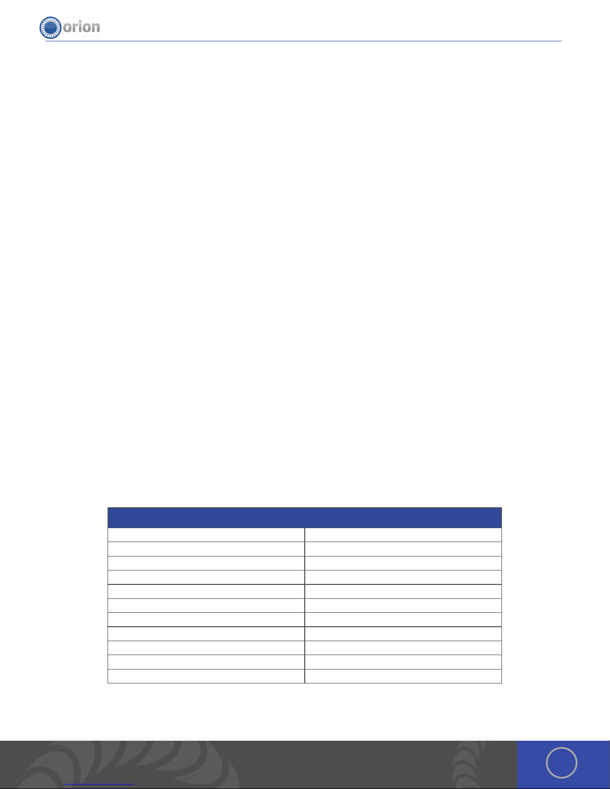
Table of Contents
Chapter 1: Setup and Assembly .................. p.5
What is in the Box ............................ p.5
Power Supply Setup .......................... p.5
Microscope Arm Setup ....................... p.6
Microscope LCD Filter Shutter ................ p.8
Become Familiar with the Microscope ....... p.8
Darkening Lens Setup ........................ p.9
Electrode Setup ............................... p.9
Shielding Gas Setup .......................... p.11
Chapter 2: Welder Interface Overview ........... p.12
Basic Screen .................................. p.12
Arc Screen .................................... p.13
Tack Screen .................................. p.14
Save/Load Screen ............................ p.14
Settings Tab .................................. p.15
Media Screen ................................. p.17
Chapter 3: Make A Weld .......................... p.18
Grey Waveform ............................... p.18
Make an Arc Weld ............................. p.18
Make a Tack Weld ............................ p.18
Orion 150s Pulse Arc and Resistance Welder
Weld Modes 4 (nano, micro, ultra, tack)
Pre-Programmed Metal Settings 11
Customizable Save Settings 50 (25 Arc & 25 Tack)
Languages 20 + (Ask rep if we have your language)
Display 8” Capacitive 10 point Touch Screen
Energy (Ws) 1-150 Ws
Switching Power Supply 110/240VAC (Auto Detected)
Weld Spot Diameter 0.5 - 3.5mm
Footprint (L x W x H) 12” x 6” x 10” (30.5 x 15.2 x 25.4cm)
Weight 20 lbs (9 kg)
Stereo Microscope Magnification 5x
3OrionWelders.com
Page 4

150s User Manual
4
Page 5
Chapter 1: Welder Setup & Assembly
What is in the Box
ALL ORION S SERIES SYSTEMS COME WITH:
(1) Safety Manual & Quick Start/Quick Settings Guide
(1) Orion s Series Power Supply
(1) Welder Power Cord
(1) Stylus Hand Piece
(2) Alligator Clips
(1) Foot Pedal
(1) Shielding Gas Hose
(1) Electrode Vial (5 – 0.5mm and 5 – 1.0mm Electrodes)
(2) Microscope Eye Piece Shields
(1) Fiberglass Brush
(1) Cross Lock Tweezers
(1) System Cover
(1) Brass Lined Pliers
IF YOU PURCHASED THE MICROSCOPE ARM SYSTEM:
(1) Orion Microscope Arm
(1) Microscope Arm Table Mount
(1) Microscope Arm Support Bar
(1) Set of Allen Wrenches
IF YOU PURCHASED THE DARKENING LENS
SYSTEM:
(1) Base Plate and Phillips Screw
(1) Base Plate Stand and Cap
(1) Darkening Lens
(1) Darkening Lens Arm
(1) RJ45 Darkening Lens to Welder Cable
Power Supply Setup
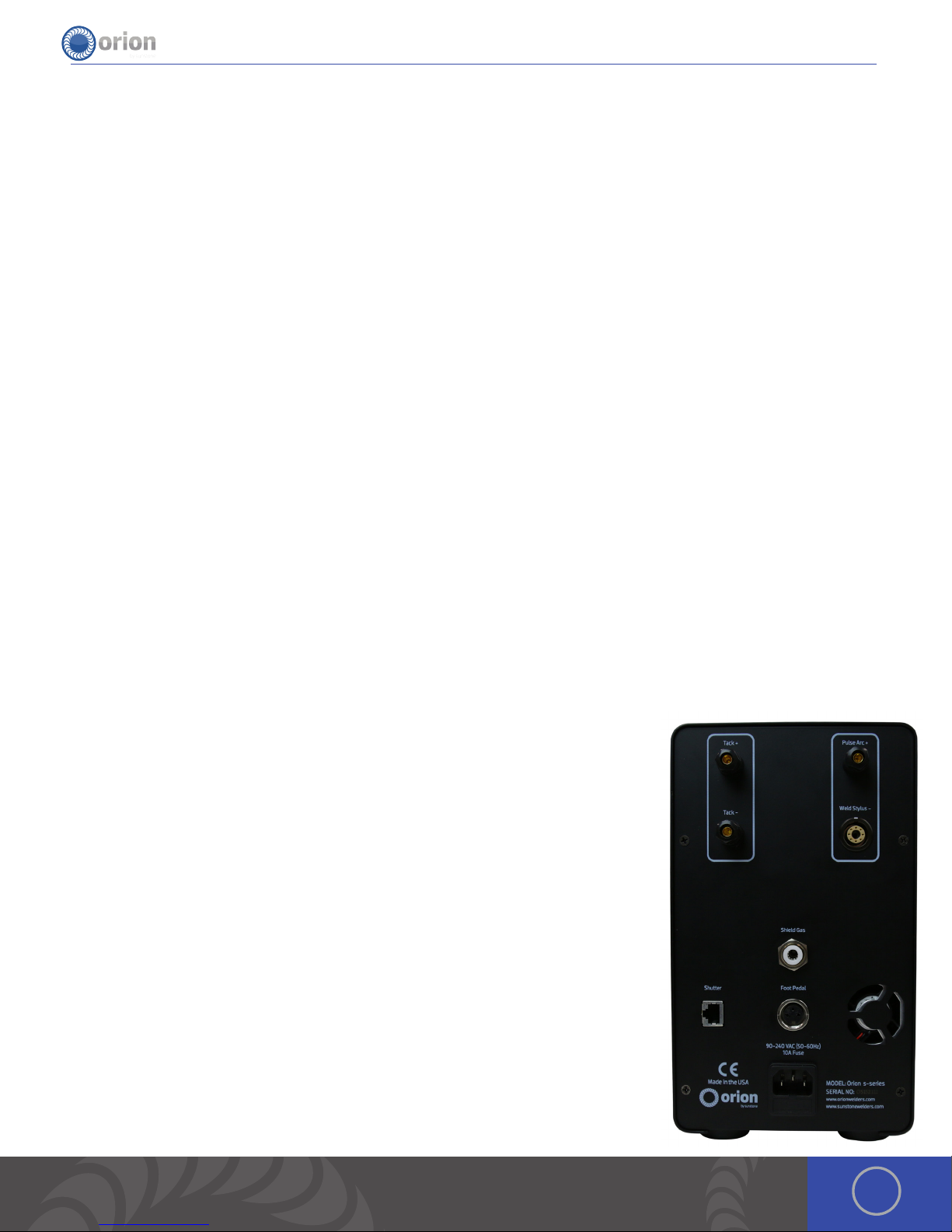
SET UP THE BACK SIDE OF THE POWER SUPPLY
e Orion has an internal switching power supply that can accept both 120 and 240VAC.
• Plug the female end of the power cable into the “90-240 VAC” Power port.
• Connect the male end of the power cable into AC power.
• Insert the 1/4” gas tube firmly into the “Shield Gas” port. *It may wiggle when
connected, but should not come out if pulled on.
• Plug the foot pedal into the “foot pedal” port.
• Plug the RJ45 microscope cable into the “Shutter” port on the back of the power
supply.
• Push the stylus into the stylus connector port on the back panel of the power
supply. Ensure that the white circular indicator on the stylus lines up with the
white indicator on the stylus port. e connector will snap into place.
• When pulse arc welding with the weld stylus, connect an alligator clip to the
“Pulse Arc +” port on the back of the welder. (If you do not use this port, use the
one on the front of the welder). *Remember to attach the alligator clip to the work
piece before pulse arc welding.
• When Tack welding, plug one alligator clip into the “Tack +” port and one into the
“Tack -” port. *Remember to attach each alligator clip to each work piece before
Tack welding them together.
5OrionWelders.com
Page 6

150s User Manual
SET UP THE FRONT SIDE OF THE POWER SUPPLY
Look to the front on the Orion to power on the welder and control the touch screen.
• Plug the pulse arc welding alligator clip in the port at the bottom right of the welder.
Alternatively, you may use the “Pulse Arc +” port on the back of the welder.
• Push in the power button on the bottom left to start the welder.
• Touch the play button on the user interface to begin welding.
Microscope Arm Setup
MICROSCOPE ARM MOUNTING OPTIONS
• Remove the microscope arm from the box and place it on your
table.
• Follow the desired mounting method below.
Mounting Option 1 - Clamp to table
• Determine the height of the tabletop. *If it is thicker than 3-1/2’
(9cm), follow mounting options 2 or 3.
• Position the microscope arm clamp under the tabletop.
• Turn the clamp knob clockwise until the clamp is very snug.
Mounting Option 2 - Bolt through table
• Using a 4mm (5/32) allen wrench, unscrew the allen bolts
holding the clamp to the arm.
• Run the included 8mm (5/16) bolt (F) through the included
plate (H).
• Attach plate (H) to the bottom of the arm using the same
allen bolts from step 1.
• Drill a 3/8’ (9.5mm) hole through the tabletop.
• Lower the arm so the bolt goes through the hole in the table
top.
• Slide the tightening plate onto the bolt and then tighten the
twist knob onto the bolt until it is very snug.
6
Page 7

Mounting Option 3 - Bolt to table
• Remove the clamp and position the base against the table.
• Trace drill holes with a pen or marker.
• Drill 1/4’ holes in the tabletop.
• Run screws through the base into the drilled holes.
MICROSCOPE SETUP
• Remove the microscope from the box and place it into the round clamp
at the top of the arm.
• Tighten the screw on the round clamp to secure the microscope to the
arm.
• Install the rubber eyepiece covers onto the microscope lenses.
• Insert the welding stylus into the stylus holder under the microscope
then tighten the stylus holder knob.
• Ensure the microscope cable is plugged into the RJ45 port on the
microscope (the bottom of the microscope head).
• Ensure the microscope cable is plugged into the “Shutter” port on the
back of the power supply.
*Orion RJ45 ports are not compatible with any other RJ45 ports. Connecting
them to other devices may damage the welder and/or the other devices.
7OrionWelders.com
Page 8

150s User Manual
• Loosen/tighten the allen on the microscope arm to adjust the spring
pressure. Turn the allen clockwise if the arm does not hold the microscope
up. Turn the allen counter clockwise if the arm does not allow the
microscope to come down.
ADJUST WELDING STYLUS POSITION
• Loosen the screws on either side of the stylus holder.
• Adjust the welding stylus to a 45-degree angle then slightly tighten the screws
on the sides just enough to hold the stylus in place at a 45-degree angle.
• While looking through the microscope, slide the welding stylus forward and
backward until the tip of the stylus is in the center of your focus.
• Now securely tighten the stylus holder by tightening the screw on the bottom of
the stylus holder.
ADJUST THE MICROSCOPE FOCUS
• Twist the knob on the microscope forward and backward to raise and lower the head.
is will allow you to focus the microscope on the welding stylus.
• Place your finger under the welding electrode to help judge the correct focus location.
Focus the microscope until the texture on the skin of your finger is clearly visible.
Microscope LCD Filter Shutter
e microscope LCD filter shutter allows an unobstructed working view before welding and completely protects the user’s
eyes during the welding process. e Orion’s internal computer verifies the microscope LCD filter shutter has been closed
before allowing the weld to take place. In the case that the shutter does not close, the microscope lens is equipped with >UV
16 and >IR 16 for maximum eye protection.
Become Familiar with the Microscope
e Orion Microscope has been designed to provide maximum visual clarity, eye protection and ease of use. One challenge
using the microscope is getting used to bringing the work piece to the welding electrode while looking through the
microscope. is is an easy challenge to overcome. To begin, follow these steps with the welder on pause. *While the welder
is on pause, it will not be able to make a weld when the work piece touches the electrode.
• Rest your hands on the table and position the work piece close to the welding
electrode before looking into the microscope.
• Make sure your focus is at the tip of the electrode.
• Use slow, controlled movements.
• It is helpful to have your hands resting and to only use your fingers to move the
work piece up to the electrode.
• Place the work piece surface perpendicular to the point of the electrode. *As
discussed in later chapters, the angle of the electrode tip relative to the work
piece surface is very important and will take practice.
8
Page 9

• Now practice making soft contact with the work piece to the electrode.
• *Once you feel comfortable, attach the alligator clip to the work piece and touch the play button to begin performing
real welds.
Darkening Lens Setup *(If you purchased the
Darkening Lens System)
SET UP THE DARKENING LENS
e Orion’s darkening lens system is easy to use. e darkening
lens will automatically darken when the weld takes place.
is allows the user to have a clear view of the work piece and
protection from the flash during the welding process.
1. Remove Darkening Lens parts from the box and place them
on your workbench.
2. Connect the Base Plate to the Base Plate Stand by running
the included Phillips screw through the bottom of the Base Plate into the Base
Plate Stand. *e Phillips screw will be attached to the bottom of the Base Plate
Stand. Unscrew it then follow this step
3. Slide the Darkening Lens Arm onto the Base Plate Stand. Adjust it to your desired
height then tighten the Arm Height Adjuster Knob.
4. Place the Base Plate Stand Cap on top of the Base Plate Stand.
5. Adjust the Darkening Lens Position by loosening/tightening the adjuster knobs
on the back of the Darkening Lens Arm.
6. Plug the Darkening Lens cable into the Darkening Lens light ring. Ensure that the
other end of the cable is securely fastened into the “Microscope” port on the
back of the welder.
7. Insert the Orion stylus into the Stylus Holder on the Darkening Lens Arm. Adjust
the position of the stylus by loosening/tightening the adjuster knobs on either
side of the Darkening Lens Arm.
DARKENING
LENS ARM
DARKENING
LENS
BASE
PLATE
BASE PLATE
STAND CAP
ARM HEIGHT
ADJUSTER KNOB
BASE PLATE
STAND
PHILLIPS
SCREW
Adjuster
knobs
DARKENING LENS
CABLE
Electrode Setup
e Orion welder comes standard with a 0.5mm electrode collet and (5) 0.5mm electrodes; and a 1.0mm
electrode collet and (5) 1.0mm electrodes. e 1.0mm electrodes are a good all around electrode while
the 0.5mm electrode is more for very small applications (less than 5ws of energy).
STYLUS COMPONENTS:
1. Stylus Shaft 2. Collet 3. Collet Cap 4. Electrode 5. Stylus Hull
9OrionWelders.com
Page 10

150s User Manual
INSTALL THE TUNGSTEN ELECTRODE ONTO THE WELDING STYLUS
Follow these steps to properly install the tungsten electrode.
• Remove the stylus hull by pulling it away from the stylus shaft.
• Loosen the collet cap by twisting it counter-clockwise.
• e welder comes with 2 electrode collets. One that fits 0.5mm
electrodes and one that fits 1.0mm electrodes. e electrode stylus will
be shipped with the 1.0mm electrode collet installed.
• Insert a 1.0mm electrode into the collet. Helpful Tip: ere is a groove cut
around the stylus hull that will help measure the electrode length. Place
the end of the stylus hull up against the collet cap, then make sure the
electrode tip falls between groove.
• ere should be between 0.6 - 0.7in (1.5 – 2cm) of the electrode
protruding from the stylus shaft. is will allow the electrode enough
room to stick out from the stylus once the stylus hull is placed back on
the stylus.)
• Lock the electrode into place by hand tightening the collet cap in a clockwise
direction.
• Replace the stylus hull by pushing it in until you feel it snap back into place
(the electrode should stick out between 1/8 – 1/4in (3.75 – 6.75mm) after the
stylus hull is snapped back into place).
WORK PIECE TO ELECTRODE PRESSURE
Touch the work piece to the electrode with very light pressure. Too much pressure will cause the work piece to stick to
the electrode and in turn cause the electrode to be contaminated (work piece material on the electrode). We recommend
cleaning or changing the electrode any time it gets stuck to the work piece
WHEN TO SHARPEN THE ELECTRODE
It is recommended that the user pay close attention to the electrode condition. An electrode that appears to be dark
colored or covered with material from previous welds can lead to inconsistent welding and poor igniting of the weld. When
this occurs, simply sharpen the electrode with the included diamond disk. e diamond disk can be attached to a flex shaft
or Dremel tool. Follow these steps for sharpening the electrode.
• Completely remove the electrode from the stylus.
• Pinch the electrode between the thumb and index and/or middle finger with the
shaft going perpendicular to the fingers.
• Power on the Dremel or flex shaft then hold it with the opposite hand. *Place the
electrode tip in the diamond disc in such a way that the grit of the disk is moving
parallel with the electrode shaft and moving towards the tip.
• is will affect the quality of the weld if not done as explained above.
• Set the electrode on the diamond disk at a 10-degree angle and begin to spin
the electrode with the thumb and middle finger. *A helpful way to get a sharp
electrode is to push down on the electrode with your index finger while twisting
the electrode with the thumb and middle finger.
• Once the electrode is sharp and clean, turn the Dremel off and insert the
electrode back into the stylus as explained above.
*As a general rule of thumb we recommend a freshly sharpened electrode anytime a
new work piece is being welded.
*See Chapter 5 for additional information on the Tungsten Electrodes
10
Page 11

WHEN TO FLATTEN/BLUNT THE ELECTRODE
When working with silver, copper, and other highly conductive metals in energy levels above 20ws, it is
recommended to blunt the electrode instead of sharpening it.
• Completely remove the electrode from the stylus.
• Pinch the electrode between the thumb and middle finger with the point facing inward.
• Turn the Dremel or flex shaft on then hold it with the opposite hand. *Place the electrode tip in the diamond
disc in such a way that the grit of the disk is moving parallel with the electrode shaft and moving towards the
tip.
• is will affect the quality of the weld if not done as explained above.
• Set the electrode on the diamond disk at a 10-degree angle and begin to spin the electrode with the thumb
and middle finger. *A helpful way to get a sharp electrode is to push down on the electrode with your index
finger while twisting the electrode with the thumb and middle finger.
• Once the electrode is sharp and clean, turn the electrode to a 90-degree angle and push it against the
dremel in order to place a flat/blunt tip on the electrode.
• Once the electrode has a flat/blunt tip, turn the Dremel off and insert the electrode back into the stylus as
explained above.
Shielding Gas Setup
During the pulse-arc welding process high temperature plasma quickly melts metal into a molten pool. As the weld is
performed, a small amount of shielding gas is released through the weld stylus to prevent oxygen from entering the molten
pool. After the weld has occurred the protective gas turns off.
If oxygen from the air enters this molten pool, the result is a metal oxide that is brittle, porous and burnt-looking. Protective
shielding gas is used, such as 99.996% pure Argon (Argon 4.6) or higher, to prevent these effects. Shielding gas is necessary
to produce clean and repeatable pulse-arc welds. We recommend high purity argon. is can be purchased at your local
welding supply shop.
PRESSURIZED GAS SAFETY
ere are several important rules that should be followed when using a compressed shielding gas such as argon.
• Always secure the pressurized gas tank to a fixed location (such as a sturdy table leg).
If the pressurized gas cylinder were to tip and become damaged there is possibility
that the tank could become rocket-like, expelling the high pressure shielding gas as
propellant.
• Always turn off the shielding gas at the main valve when finished. is will help your
shielding gas supply last longer in case there is a small leak in the tubing. is is also a
good safety practice. If the tube becomes dislodged shielding gas could fill the room
and displace oxygen, which can lead to suffocation. Argon is heavier than air and will fill
the room from the bottom upward. If you experience a large shielding gas leak, open all
of the doors and windows in the room.
SHIELDING GAS TANK AND REGULATOR SETUP
• Ensure that your shielding gas tank is securely fastened to a stationary point near
the welding area.
• Turn the regulator dial COUNTER CLOCKWISE (closed) until it is fully backed out.
meaning the dial become loose, to prevent over-pressurization of the line.
Regulator Dial
11OrionWelders.com
Page 12

150s User Manual
• Screw the gas regulator onto the shielding gas tank.
• Connect one end of the gas tubing to the gas regulator.
• Insert the other end of the gas tubing into the gas port on the back of the power
supply. It will stop when it is fully connected. Tug gently on the tube to verify a
tight fit.
• Open the gas tank slowly. e dial on the right should pressurize and the dial on
the left should remain at zero (when the regulator dial is fully backed out or the
dial becomes loose).
• Slowly turn the regulator dial CLOCKWISE until the gas pressure reads between
7-10 psi. (is will adjust the dial on the left side of the regulator.)
Chapter 2: The Touch Screen Interface
Below is an explanation of all the various buttons and options found on the Orion user interface.
Basic Screen
1. Screen Select Drop Bar: is allows users to switch between the different welding screens; Basic, Arc, Tack.
2. Media Screen Button: is allows users to access the multimedia screen.
3. Save / Load Screen Button: is allows users to access the save load screen.
4. Settings Button: is allows users to access the settings screens.
5. Power per division graph: Depending on the current weld bank you are in, displays the energy limits.
6. Graph PSI: Displays the PSI of the unit in real time.
7. Graph Estimated Spot Size: Displays the estimated spot size that will be produced.
8. Graph Energy: Displays the energy based on current settings of the welder.
9. Graph Weld curve: A graphical representation of the weld curve that will be produced.
10. Graph Agitation: A graphical representation of the agitation of the weld.
11. Graph Length of Weld: Displays the length of the weld based on current settings.
12. Graph Weld Settings: Shows the ignition setting, agitation setting, weld length and welds per second of the current weld
settings.
13. Metal Select Scroll View : Unique to the basic screen this allows a user to select the metal they are going to weld and
load recommended settings based on Sunstone’s experienced welders.
14. Application Selector Button: Large Joint: Unique to the basic screen, users can select the application that they are going
to weld and receive recommended settings based on Sunstone’s experienced welders.
15. Application Selector Button: Small Joint: Unique to the basic screen, users can select the application that they are going
to weld and receive recommended settings based on Sunstone’s experienced welders.
12
Page 13

16. Application Selector Button: Corner Weld: Unique to the basic screen,
users can select the application that they are going to weld and receive
recommended settings based on Sunstone’s experienced welders.
17. Application Selector Button: Add Metal to a piece: Unique to the basic
screen, users can select the application that they are going to weld
and receive recommended settings based on Sunstone’s experienced
welders.
18. Application Selector Button: Prong: Unique to the basic screen, users
can select the application that they are going to weld and receive
recommended settings based on Sunstone’s experienced welders.
19. Incremental Decrease Button: is allows the users to step down
incrementally for added precision.
20. Energy Slider Bar with Estimated Spot Size Calculator: e estimated
spot size is displayed directly above the energy slider bar. Features 6
displayed spot sizes so that users can quickly snap to an appropriate
energy.
21. Incremental Increase Button: is allows the users to step up
incrementally for added precision.
22. Welds Per Second Slider Bar: is allows users to adjust the fire rate of
their welder. As users increase this bar the welder produces rapid fire
welds from 1 to 5 welds per second.
23. Play / Pause Button: Toggles the welder from Weld Off (Pause) to Weld
On (Play)
24. Undo Button: Step backwards through the previous touches.
25. Redo Button: Step forward through the previous touches.
26. Reset Button: Clears all the weld settings to a preset factory default.
*Note, reset will not affect any saved settings or multimedia items
saved on the welder.
27. Touch Detect Button: is changes the welder to a touch detect trigger mode. Initiating the weld when the work piece
comes into contact with the welder electrode.
28. Foot Pedal Button: is changes the welder to a foot pedal trigger mode. Allowing the user to initiate the weld when
they desire.
Arc Screen
1. Length Slider Bar: is allows the user to make quick adjustments to the
length of the weld.
2. Agitation Group: is grouping of buttons allows the user to quickly
change what agitation they would prefer on the fly.
a) No Agitation: As the name implies this creates just a classic
discharge of energy without any agitation added during the weld
process.
b) Sloped Agitation: With sloped agitation a certain level of
increased energy is present throughout the entire weld but
decreases as the welds classic energy decreases.
c) Sustained Agitation: With sustained agitation the welder maintains a peak agitation throughout the weld.
d) Negative Agitation: If the user is welding a metal that is prone to porosity negative agitation will help.
3. Percentage Of Weld Slider Bar: is allows the user to change what percentage of their weld includes agitation.
4. Ignition Group: is grouping of buttons allows the user to quickly change their ignition settings.
e) Standard: e regular way of making a weld.
f) Standard +: With standard + the welder turns on the low current ignition (LCI) circuit to help create that arc. is
makes welding at lower ranges a little easier and keeps the electrode from becoming contaminated.
a.
b.
2
e.
1
c.4d.
3
f.
13OrionWelders.com
Page 14

150s User Manual
Tack Screen
1. Tack Energy Slider: Adjusts the amount of weld energy that is being
used.
QUICK POWER SETTINGS: ese buttons allow the user to quickly
set a power setting that they would like.
2. Low: With the Low setting the welder is set to 30 ws.
3. Medium: With the medium setting the welder is set to 100 ws
4. High: With the high setting the welder is set to 150 ws.
PREWELD DELAY: ese buttons set the time before a weld will
initiate.
5. Short: With the short setting the welder will wait for a quarter
second before initiating the weld.
6. Medium: With the medium setting the welder will wait for half a
second before initiating the weld.
7. Long: With the long setting the welder will wait for one second
before initiating the weld.
Save/Load Screen
1. Current Weld Settings Graph: Displays the current weld settings
for the user to see.
2. Left / Right saved settings scroll list: Allows the user to scroll
through the saved welds to choose one for loading or saving over.
3. Name of weld to save: Allows the user to name the weld before
saving.
4. Notes about saved weld: Allows the user to input any important
information about a weld.
5. Save as New Button: Saves the current weld settings and notes
under the name that has been provided. If no name was provided
the name will be “No Name”.
6. Load Button: Loads the selected saved weld into the current
settings.
7. Save Over Selected Weld Button: Saves the current weld setting
and notes over the currently selected saved weld.
8. Delete Selected Weld Button: Deletes the selected saved weld
from the welder.
9. Exit Button: Allows the user to return to the “arc” screen.
14
Page 15

Settings Tab
INTERFACE SCREEN
1. Interface Button: Allows the user to switch the setting screen
displayed to the interface settings page.
2. Gas Button: Allows the user to switch the setting screen displayed
to the gas settings page.
3. Timing Button: Allows the user to switch the setting screen
displayed to the timing settings page.
4. System Button: Allows the user to switch the setting screen
displayed to the system settings page.
5. Language Menu: Allows the user to select a display language from
the wide array of languages supported by Sunstone.
6. eme Menu: Allows the user to select a visual theme to fit their
liking. Currently they can pick from; Blue skies which is the default
blue theme, Green Leaf which is a light green color, Golden Sunrise
which is a pleasant orange hue, and Obsidian which is a high contrast
black theme.
7. Volume Slider Bar: Allows the user to adjust the volume of the
system. (Note: this only changes the volume of errors / videos / the
startup music)
8. Microscope Brightness Slider Bar: Allows the user to adjust the
brightness of the LED’s around the microscope.
9. Screen Brightness Slider Bar: Allows the user to adjust the
brightness of the LCD screen of the welder.
GAS SCREEN
1. PSI Knob: Allows the users to see a visual representation of the
welders PSI.
2. Calibrate Gas Button: Allows the users to recalibrate the gas
pressure to make sure the gas read out is accurate. Be sure that
when calibrating the gas pressure, no gas should be connected to
the welder.
3. Purge Gas Button: Allows the users to purge the line of air and or
gas, useful for pressurization.
4. Pre-Flow Delay Slider: Allows the user to set how long the gas
will be on before the weld initiates. e welder will automatically
increase this time if a weld hasn’t occured for a given time in order to
purge the line and decrease oxygen at the weld location.
5. Post-Flow Delay Slider: Allows the user to set how long the gas will
remain on after a weld has taken place. Longer delays are useful
for metals that oxidize quickly,such as titanium, where oxygen will
cause cracks while the molten metal is cooling.
15OrionWelders.com
Page 16

150s User Manual
TIMING SCREEN
1. Pre-Weld Delay Slider: Changes the delay from when a weld is initiated
and when the weld will occur.
2. Lift-off Delay Slider: Adjusts the timing of when the welder retracts the
electrode.
3. Post-Weld Shutter Delay Slider: Adjusts the amount of time after a
weld and before the shutter lightens.
4. Minimum Time Between Welds Slider: Adjusts the amount of time that
the welder will wait before allowing another weld to initiate.
5. Duty Cycle Slider: Adjusts the percent that the agitation is on.
SYSTEM SCREEN
1. Restore All Defaults Button: Just like the Basic, Arc, and Tack screen’s
“Reset” is allows the user to restore the weld settings to a default
state as set by Sunstone.
2. Clear All Memory Button: In addition to restoring all the weld settings
this button allows the user to clear any saved settings including but not
limited to; saved welds, stored preferences.
3. Update Welder over Wifi: Allows the user to update their system from
the Sunstone Server Via Wifi.
4. Disconnect From Wifi: Allows the user to turn off their Wifi. When a user
isn’t connected to Wifi this button changes to a Connect to Wifi allowing
the user to connect to their network.
5. Enter Test Suite: Allows the user, with the help of Sunstone Support, to
enter a diagnostic screen.
6. Hardware Revision: Displays the revision number of the control board.
7. Firmware Revision: Displays the revision number of the control board’s
firmware.
8. LCD Revision: Displays the revision number of the LCD
9. Support Information: Displays to the user a way to get a hold of
Sunstone’s amazing support.
UPDATING WELDER SOFTWARE
Orion users are able to receive software and welder setting updates via email. As Orion engineers develop new software
with more efficient settings and/or features to help users have the very best welding experience, they will place the update
on the Orion website for user to download.
16
Page 17

1. Download update ZIP file from website or email . 2 . Unzip file, which produces files called
“150Supdate.apk”.
3 . Plug USB into computer then Place the
files in the root directory of the USB thumb drive . (Do not place the files into any subdirectory or folder on the USB drive and
do not rename the update file or the welder will not be able to perform the update .)
4 . Plug the USB thumb drive into the USB port on the back of the welder .
5 . If the welder isn’t turned on, turn the welder on .
6 . Go to the Settings screen, by pressing the icon on the top right of the screen.
7. Press the update button and choose to update via USB.
8. A few popups will show up indicating the progress of the update. Once the update process is complete and reaches 100%,
the welder will return to the main screen.
Update via Wifi:
1 . Go to the Settings screen, by pressing the icon on the top right of the screen.
2. Press the update button and choose to update via Wifi. (is will update the welder to the latest software available.)
3. A few popups will show up indicating the progress of the update. Once the update process is complete and reaches 100%,
the welder will return to the main screen.
Media Screen
1. Pop Out Arrow: is arrow allows the
user to bring out a menu and select
a video or manual to view on the
welder.
7.
2. Media Bar: is menu (only usable
with a video) allows the user to
perform the basic video operations
with a video that has been selected.
3. Rewind: Allows the user to rewind in
two second intervals.
4. Play: Plays or pauses the current
video
5. Fast Forward: Allows the user to skip
ahead five seconds.
6. Seek Bar: Allows the user to “scroll”
to whatever part of the video they
would like.
7. File List: When the menu is pulled
out the user will see various folders
that may vary from the screen shot
provided. With this list the user is
able to select between manuals and
videos and the different manuals or movies they would like to view.
8. Pop In Arrow: is arrow allows the user to collapse the menu and return to viewing either manual or movie.
9. Load Settings from Video: Touch this button to load the suggested settings from the video to your arc screen. You can
adjust the settings up and down to personalize your parameters based on the work piece you are welding.
1.
9.
8.
3. 4. 5. 6.
2.
17OrionWelders.com
Page 18

150s User Manual
Chapter 3: Make a Weld
Grey Waveform
• When the welder is paused the waveform screen will appear grey.
Remember to push play in order to perform welds.
Make An Arc Weld (using the provided weld plate)
1. From the Arc Screen select 16 Ws on the Energy bar, 15 ms on the Length bar,
Reverse Agitation from the Agitation options, 51 on the Percentage of Weld bar,
Standard from the Ignition options, Single Fire on the Welds Per Second bar,
Touch Detect for trigger type, and then hit Play. *Remember to verify the gas
pressure and microscope connection, .
2. Lightly touch the electrode in the box on
the provided weld plate. Maintain contact &
keep hands steady by resting them on the
table.
3. Use the provided stainless steel weld
plate as a guide to try different settings.
Make several welds on the weld plate to
get comfortable with the stylus and the
different weld parameters.
Make a Tack Weld
1. Select Medium from the Quick Power Settings row, Short from the Pre-Weld
Delay row, Foot Pedal for the Trigger Type, and then touch the Play button.
2. Attach the negative alligator clip to one work piece and the positive alligator
clip to the other work piece.
3. Lightly touch the two work pieces together
where you want to tack them.
4. Step on the foot pedal.
5. If the work pieces stay together, proceed to
the Arc screen to perform a permanent weld
using the Pulse Arc Welding Stylus. If the pieces
do not stay together, move the Total Energy up
and repeat steps 2-4.
18
Page 19

Electrode Shaping:
Stylus Cone
Stylus Cone
Sharp Electrode Tip
Electrode placement examples:
Butt Weld
T-Joint Weld
Add Metal Weld
General Settings:
26 AWG wire/chain/jump ring
Metal Tip Shape Energy Length Agitation
14k Gold Sharp 9 ws 15 ms None
24k Gold Sharp 8 ws 15 ms None
Silver Sharp 10 ws 15 ms None
Platinum Sharp 10 ws 15 ms None
Stainless Sharp 8 ws 15 ms Sloped
Palladium Sharp 7 ws 15 ms Sustained
Titanium Sharp 10 ws 15 ms None
Brass Sharp 9 ws 15 ms None
0.5mm thick Ring
Metal Tip Shape Energy Length Agitation
14k Gold Sharp 12 ws 15 ms None
24k Gold harp 11 ws 15 ms None
Silver Sharp 17 ws 15 ms None
Platinum Sharp 15 ws 15 ms None
Stainless Sharp 14 ws 15 ms Sloped
Palladium Sharp 13 ws 15 ms Sustained
Titanium Sharp 15 ws 15 ms None
Brass Sharp 15 ws 15 ms None
Flat Electrode Tip
Add Metal Weld
Add Metal Weld
Earring Post
Metal Tip Shape Energy Length Agitation
14k Gold Sharp 11 ws 15 ms None
24k Gold Sharp 10 ws 15 ms None
Silver Sharp 12 ws 15 ms None
Platinum Sharp 12 ws 15 ms None
Stainless Sharp 9 ws 15 ms Sloped
Palladium Sharp 8 ws 15 ms Sustained
Titanium Sharp 12 ws 15 ms None
Brass Sharp 11 ws 15 ms None
1mm thick Ring
Metal Tip Shape Energy Length Agitation
14k Gold Sharp 22 ws 15 ms None
24k Gold Sharp 20 ws 15 ms None
Silver Semi Blunt 45 ws 15 ms None
Platinum Sharp 24 ws 15 ms None
Stainless Sharp 22 ws 15 ms Sloped
Palladium Sharp 19 ws 15 ms Sustained
Titanium Sharp 26 ws 15 ms None
Brass Sharp 26 ws 15 ms None
2mm thick Ring
Metal Tip Shape Energy Length Agitation
14k Gold Sharp 50 ws 60 ms None
24k Gold Sharp 45 ws 60 ms None
Silver Blunt 80 ws 60 ms None
Platinum Sharp 60 ws 60 ms None
Stainless Sharp 45 ws 60 ms Sloped
Palladium Sharp 40 ws 60 ms Sustained
Titanium Sharp 55 ws 60 ms None
Brass Sharp 55 ws 60 ms None
Add Material (24 AWG wire)
Metal Tip Shape Energy Length Agitation
14k Gold Sharp 17 ws 15 ms None
24k Gold Sharp 16 ws 15 ms None
Silver Sharp 18 ws 15 ms None
Platinum Sharp 18 ws 15 ms None
Stainless Sharp 14 ws 15 ms Sloped
Palladium Sharp 13 ws 15 ms Sustained
Titanium Sharp 18 ws 15 ms None
Brass Sharp 17 ws 15 ms None
Add Material (30 AWG laser wire)
Metal Tip Shape Energy Length Agitation
14k Gold Sharp 13 ws 15 ms None
24k Gold Sharp 12 ws 15 ms None
Silver Sharp 14 ws 15 ms None
Platinum Sharp 14 ws 15 ms None
Stainless Sharp 10 ws 15 ms Sloped
Palladium Sharp 9 ws 15 ms Sustained
Titanium Sharp 14 ws 15 ms None
Brass Sharp 13 ws 15 ms None
Retip Prong (26 AWG wire)
Metal Tip Shape Energy Length Agitation
14k Gold Sharp 9 ws 15 ms None
24k Gold Sharp 8 ws 15 ms None
Silver Sharp 10 ws 15 ms None
Platinum Sharp 10 ws 15 ms None
Stainless Sharp 8 ws 15 ms Sloped
Palladium Sharp 7 ws 15 ms Sustained
Titanium Sharp 10 ws 15 ms Sloped
Brass Sharp 9 ws 15 ms None
19OrionWelders.com
Page 20

 Loading...