

Page 1

www.orioncontrols.com
®
PT-Link II BACnet3
Technical Guide
RNE Controller Code: SS1045
VCB-X Controller Code: SS1051 Version 2.0
VCM-X Controller Code: SS1026 & Y200920 Version 2.0 and up;
VCM-X Modular Controller Code: SS1030 & SS1034
VCM-X WSHP Controller Code: SS1032 & SS1033
SA Controller Code: Y200921
VCM Controller Code: SS1016, Y200409, Y200616, Y200822
Page 2

Zone
TABLE OF CONTENTS
Zone
1. GENERAL INFORMATION ................................................................................. 4
1.1 Overview and System Requirements ................................................................................................................4
1.1.1 Data Sharing ............................................................................................................................................4
1.1.2 Scheduling ...............................................................................................................................................4
1.1.3 Hardware Specifi cations ..........................................................................................................................4
1.1.4 System Requirements .............................................................................................................................4
2. SETTING UP YOUR PT-LINK II ......................................................................... 5
2.1 Quick Start Guide ..............................................................................................................................................5
2.2 Connection and Wiring Information ...................................................................................................................6
2.3 Confi guring the PT-Link DIP Switches ..............................................................................................................7
2.3.1. Set the BACnet MS/TP Baud Rate ..........................................................................................................7
2.3.2. Set the BACnet MS/TP MAC Address .....................................................................................................7
3. PT-LINK CONFIGURATION ............................................................................... 8
3.1 FS-GUI ..............................................................................................................................................................8
3.2 PT-Link II Ethernet Connection .........................................................................................................................9
3.3 IP Address Confi guration ................................................................................................................................10
3.3.1 Computer IP Address Set-up for Windows XP, Vista, 7 & 8 ..................................................................10
3.3.1.1 Computer IP Address Set-up for Windows NT & XP .................................................................10
3.3.1.2 Computer IP Address Set-up for Windows Vista, 7 & 8 ............................................................. 11
3.3.2 BACnet MS/TP: Setting Node_Offset to Assign Specifi c Device Instances ......................................... 12
3.4 Changing the Confi g.sys File ................................................................................................................... .......13
3.4.1 Verifying Communications .....................................................................................................................15
4. UPDATING THE SOFTWARE ........................................................................... 16
4.1 Updating the PT-Link II Controller ...................................................................................................................16
4.1.1 Programming the PT-Link II with BootLoader ........................................................................................16
4.1.2 Finding What COM Port Number the PT-Link II is Using .......................................................................18
4.1.3 Changing the USB COM Port Number ..................................................................................................19
4.2 Updating the Field Server Software ................................................................................................................20
WattMaster Controls, Inc.
8500 NW River Park Drive · Parkville, MO 64152
Toll Free Phone: 866-918-1100
PH: (816) 505-1100 · FAX: (816) 505-1101 · E-mail: mail@wattmaster.com
Visit our web site at www.orioncontrols.com
Form: OR-PTLNK3BTL-TGD-01D
Copyright June 2015 WattMaster Controls, Inc.
BACnet® is a registered trademark of ASHRAE Inc., Atlanta, GA.
FieldServer is a Registered Trademark of FieldServer T echnologies, Milpetas, CA
WattMaster Controls, Inc. assumes no responsibility for errors or omissions.
This document is subject to change without notice.
2
PT-Link II BACnet3 Interface
Page 3

TABLE OF CONTENTS
5. TROUBLESHOOTING ...................................................................................... 21
5.1 Troubleshooting Communications ...................................................................................................................21
5.1.1 Check Wiring and Settings ....................................................................................................................21
5.1.2 Verifying Communications .....................................................................................................................21
5.2 Troubleshooting LEDs .....................................................................................................................................22
5.2.1 PT-Link Board LEDs ..............................................................................................................................22
5.2.2 PT-Link Module LEDs ............................................................................................................................23
5.3 Troubleshooting the PT-Link Controller ...........................................................................................................24
5.3.1 Addressing WattMaster Devices in a BACnet® Network. ......................................................................24
5.3.2 CAS BACnet Explorer for Validating PT-Link in the Field ......................................................................24
5.3.2.1 Downloading the CAS Explorer and Requesting an Activation Key .......................................... 24
5.3.2.2 CAS BACnet MS/TP Setup ........................................................................................................25
5.3.3 Viewing Diagnostic Information .............................................................................................................25
5.4 FieldServer Diagnostic Utilities .......................................................................................................................26
5.4.1 Diagnostic Capture Procedures ............................................................................................................. 26
6. DATA ARRAYS ................................................................................................. 28
6.1 VCB-X & VCM-X Modular Data Arrays ...........................................................................................................28
6.2 VCM-X WSHP Coil & VCM-X WSHP Tulsa / RNE Data Arrays ......................................................................29
6.3 VCM-X & SA Data Arrays ................................................................................................................................30
6.4 VCM Data Array ..............................................................................................................................................31
7. PARAMETER TABLES ..................................................................................... 32
7.1 VCB-X BACnet Parameters ............................................................................................................................33
7.1.1 VCB-X PT-Link II BACnet® Property Identifi er ......................................................................................43
7.2 VCM-X Modular BACnet Parameters .............................................................................................................44
7.3 VCM-X WSHP (Tulsa) & RNE BACnet Parameters ........................................................................................45
7.4 VCM-X WSHP (Coil) BACnet Parameters ......................................................................................................47
7.5 VCM-X PT-Link II BACnet® Property Identifi er ...............................................................................................48
7.5.1 VCB-X PT-Link II BACnet® Property Identifi er ......................................................................................53
7.6 SA Controller BACnet Parameters ..................................................................................................................54
7.6.1 SA Controller PT-Link-BACnet®Property Identifi er:...............................................................................57
7.7 VCM BACnet Parameters ...............................................................................................................................58
7.7.1 VCM PT-Link II BACnet® Property Identifi er: ........................................................................................63
8. FIELDSERVER GRAPHICAL USER INTERFACE .............................................. 64
8.1 The FieldServer Graphical User Interface (FS-GUI) with Confi guration Parameter page Navigation Tree ....64
8.2 Network Settings .............................................................................................................................................65
8.3 Setting a Password for the FS-GUI .................................................................................................................65
9. NODE ID (DEVICE INSTANCE) & MAC ADDRESS ........................................... 67
10. BACNET PIC STATEMENT ............................................................................ 70
10.1 Protocessor Driver - (PICS) BACnet Protocol Implementation Conformance Statement .............................70
PT-Link II BACnet3 Interface
3
Page 4

Zone
1. GENERAL INFORMATION
1.1 Overview and System Requirements
Zone
The OE368-23B-BACNET3, PT -Link II BACnet® provides bi-directional communication between your BACnet® MS/TP protocol network and
up to four* of any of the following types of Orion controllers—VCM-X,
VCB-X, RNE, SA, VCM, MUA II, or VAV/CAV:
VCM-X Controller (SS1026, SS1030, SS1032, SS1033,
SS1034, Y200920)
VCB-X Controller (SS1051)
RNE Controller (SS1045)
SA Controller (Y200921)
VCM Controller (SS1016, Y200409, Y200616, Y200822)
**VAV/CAV Controller (SS1003, Y200301) and
MUA II Controller (SS1004, Y200405)
To determine what controller you have, you must look at the label located
on the controller. NOTE: The label is located on the EPROM on older
devices. If the controller label does not match any of the SS or Y numbers
listed above, your controller will not work with the PT -Link II BACnet®.
*NOTE: The PT-Link II BACnet® device can be used to con-
nect to four Orion controllers. If more than four Orion
controllers are present in a system, you will need additional PT-Link II BACnet® devices.
1.1.2 Scheduling
• Allows BACnet
to the Orion controller side of the gateway by using
standard BACnet® services.
®
devices to send Schedule events
1.1.3 Hardware Specifi cations
Technical Data
BACnet®-MS/TP Loop
Controller Loop
Network Protocol
Protocol
(WattMaster Loop)
Power Input Voltage
Power Consumption
Operating T emp
Operating Humidity
Weight
Table 1: PT-Link II BACnet® Interface
Technical Data
9600, 19200, 38400, 76800 Mbps
RS-485, 9600 Baud Rate
BACnet®
HSI Open Protocol Token Passing
24 VAC
10 VA Maximum
-30°F to 150°F
90% RH Non-Condensing
4.5 oz.
**NOTE: Documentation is available for MUA II/VAV/CA V on
our Orion Controls website: www.orioncontrols.com.
1.1.1 Data Sharing
• Provides values from points on the Orion side of the
gateway to BACnet® devices as if the values were
originating from BACnet® objects.
• Allows BACnet
Orion controller side of the PT-Link II BACnet® by using
standard BACnet
®
devices to modify point values on the
®
write services.
1.1.4 System Requirements
• The PT-Link II BACnet
assembled for panel mounting. Panel mounting components
are included for your convenience.
• Computer running Microsoft Windows
system.
®
interface is packaged and
TM
operating
• Ethernet Crossover Cable (supplied).
• PT-Link II BACnet software—located on included CD-
ROM and downloadable from www.orioncontrols.com.
4
PT-Link II BACnet3 Interface
Page 5
2. QUICK PT-LINK SET-UP
2.1 Quick Start Guide
The following steps will get you up and running in no time:
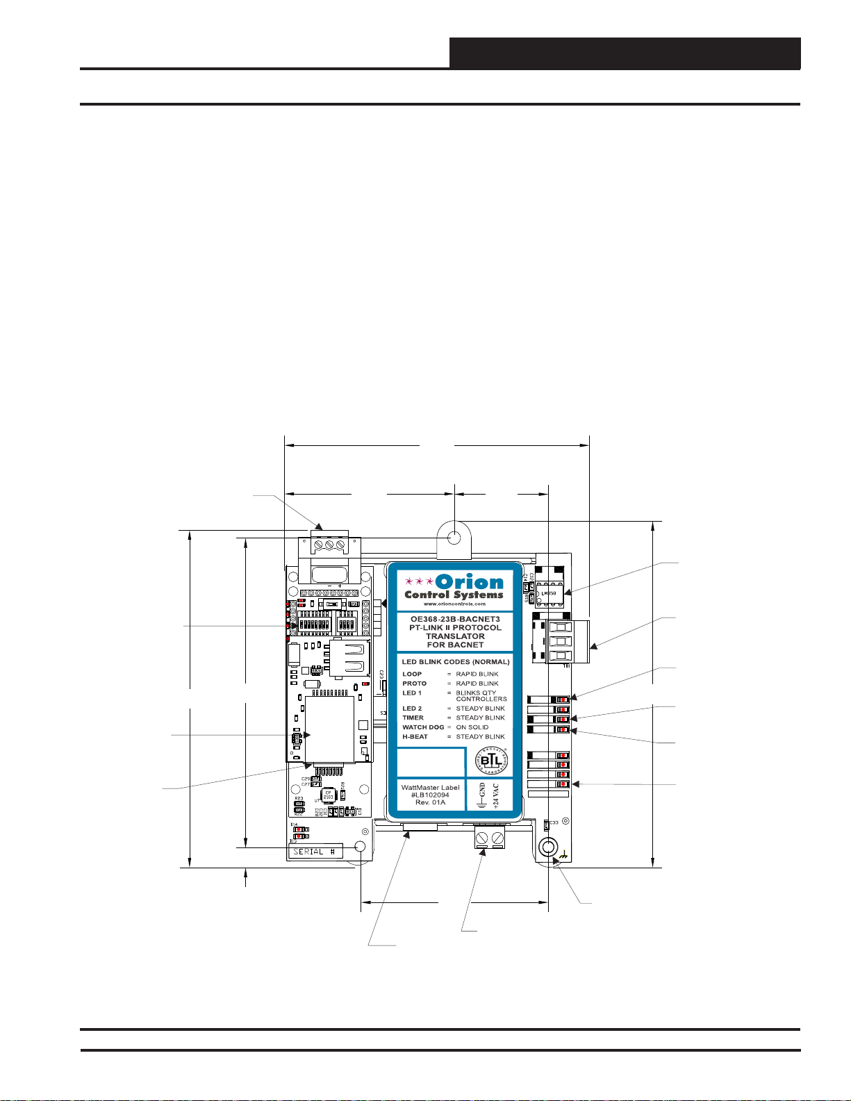
1. Familiarize yourself with the PT-Link II components (Figure 1).
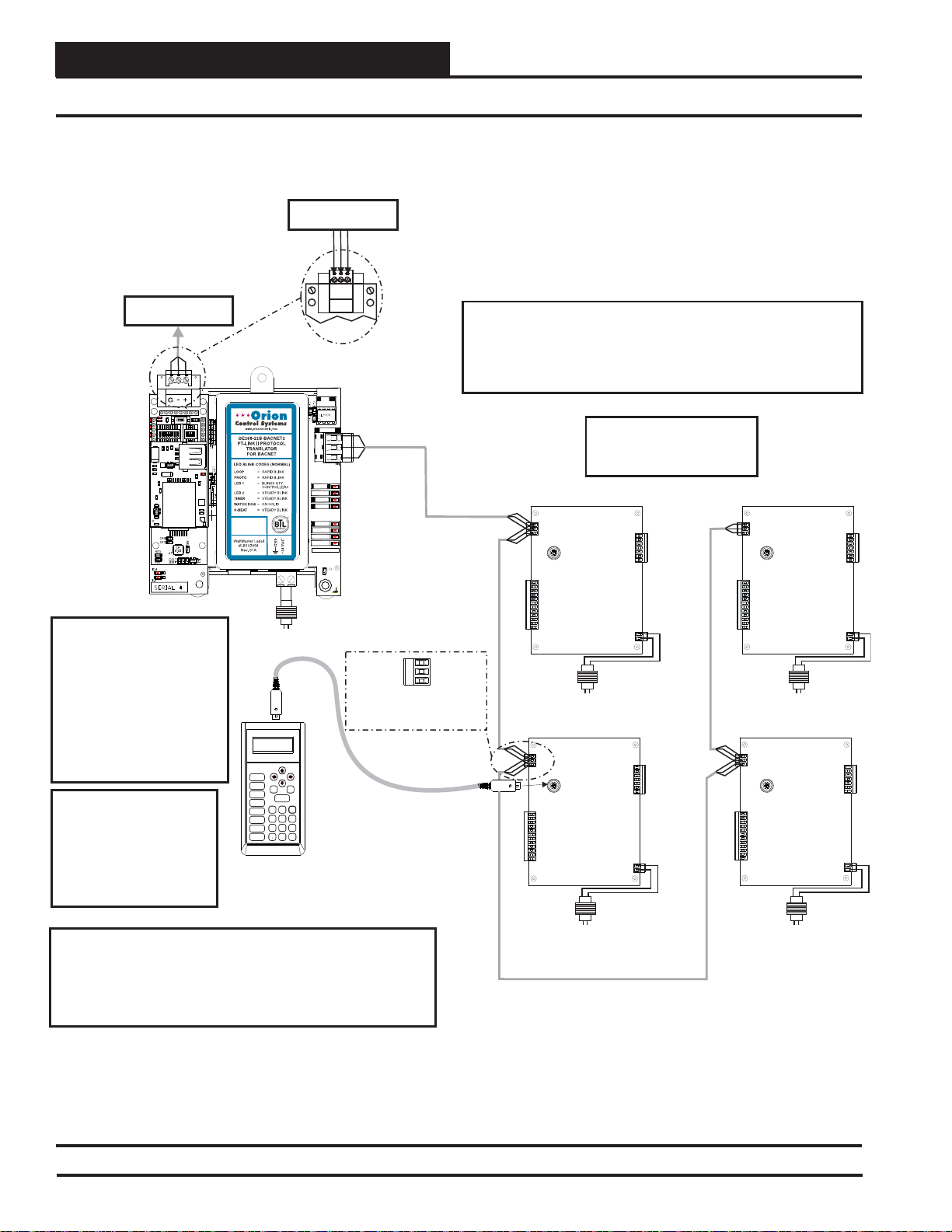
2. Connect your PT-Link II to the Controller(s) on your system (up
to four) and connect your PT-Link II to the BACnet Network
(Figure 2). NOTE: Controllers must be addressed as
1, 2, 3 & 4.
3. Obtain the following from your Building Automation System
Integrator: the BACnet MAC address (System Node ID) and the
MS/TP network baud rate. Also, relay to your System Integrator
that the BACnet Device Instance Number for the PT-Link will be
the MAC address + 50,000. If this Device Instance will not work,
then continue to the full setup.
®
BACnet
Communications
Wiring Terminal
2.37
4. Confi gure your PT Link DIP Switches. See Section 2.3, page 7.
• Set the BACnet MS/TP baud rate via the B Bank set of DIP
switches.
• Set the BACnet MS/TP MAC Address using the PT-Link A
Bank DIP switches. The BACnet MS/TP MAC Address
MUST be set between 1 and 127.
4.25
1.31
Configuration
DIP Switches
®
BACnet
Protocessor
Module
Ethernet
Port
4.70
4.31
0.27
O
N
2
1
IAEZH004
Made in USA
RSGND
345
678
485
DRIVER
Local Loop
Communications
Driver Chip
ON
O
N
4
2
3
1
COMM
R
SH
T
Local Loop
Communications
Wiring Terminal
Communications
LED
4.82
Diagnostic
LED #1
Diagnostic
LED #2
Power
LED
2.61
LOOP
PROTO
LED1
LED2
TIMER
W_DOG
H-BEAT
POWER
MADE IN USA
0.20 Dia.
Mounting Hole
Typ. 3 PL.
USB
24 VAC Power
Terminal
Port
Figure 1: PT-Link II BACnet® Dimensions and Components
PT-Link II BACnet3 Interface
5
Page 6
2. QUICK PT-LINK SET-UP
2.2 Connection and Wiring Information
Zone
Zone
MS/TP Connection
To Network
BACnet
®
MS/TP Connection
To Network
BACnet
®
PT-Link Interface
485
RSGND
ON
O
O
N
N
4
2
345
678
2
3
1
1
Caution: The BACnet
®
Communication Terminal Block
Line Voltage
DRIVER
COMM
R
SH
T
LOOP
PROTO
LED1
LED2
TIMER
W_DOG
H-BEAT
POWER
MADE IN USA
24 VAC
(10 VA)
Must Be Disconnected Before
Connecting The Modular
Service Tool. After
Programming The
Controller(s), Disconnect The
Service Tool and Then
Typical Terminal Blocks. All
Wiring To Be T To T, SHLD
(G) To SHLD (G) & R To R
Reconnect The
Communication Terminal
Block.
Note: All Programming Of
Controllers Must Be Done
Using The Modular Service
Tool. The Modular System
Manager Should Not Be
Used On A System That
Modular Service Tool
Mode
Selection
STATUS
SETPOINTS
SCHEDULES
OVERRIDES
ALARMS
CONFIGURATION
BALANCE - TEST
ON
UP
PREV
DOWN
ESC
ENTER
13
2
708
DEC
NEXT
CLEAR
654
9
MINUS
-
Has A PT-Link Installed.
Wiring Notes:
1.) All wiring to be in accordance with local and national electrical
codes and specifications.
IMPORTANT WIRING NOTE:
Use the Daisy-Chain Topology As Shown in This Diagram.
DO NOT Use a Star Topology with Multiple Units Tied
Directly to the PT-Link II.
Up To 4 Controllers
Can Be Interconnected.
Address Controllers
As Shown.
Controller
Address 1
T
SHLD
R
24 VAC
(8 VA)
Line Voltage
Controller
Address 3 Address 4
24 VAC
(8 VA)
Line Voltage
Controller
Address 2
24 VAC
(8 VA)
Line Voltage
Controller
24 VAC
(8 VA)
Line Voltage
2.) All communication wiring to be 18 gauge minimum, 2 conductor
twisted pair with shield. Use Belden #82760 or equivalent.
Figure 2: PT-Link II BACnet® Interface Wiring
6
PT-Link II BACnet3 Interface
Page 7
2. QUICK PT-LINK SET-UP
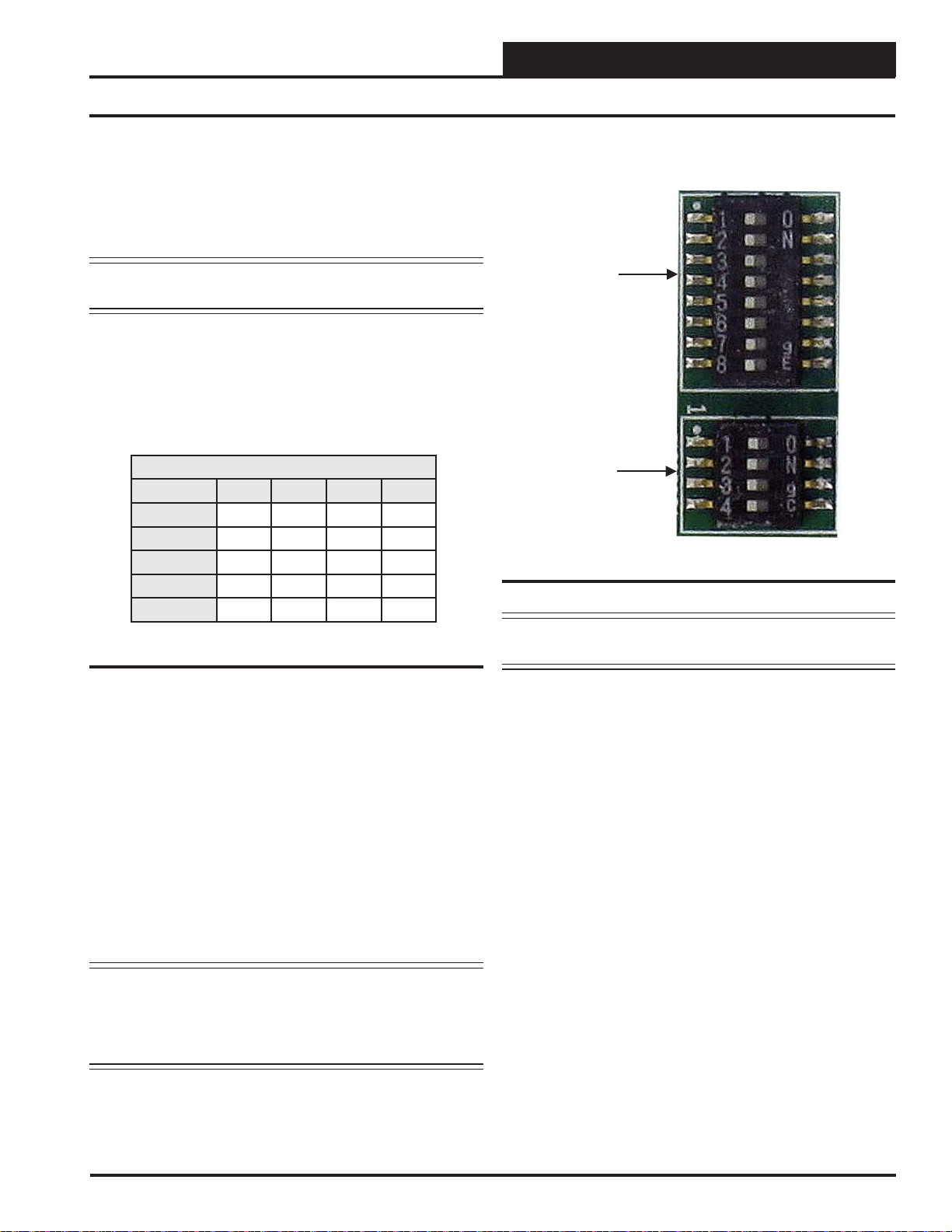
2.3 Confi guring the PT-Link DIP Switches
The DIP Switches allow you to set the protocol between BACnet MS/TP
and BACnet IP, set the BACnet MS/TP Baud Rate, and set the BACnet
MS/TP MAC address, and set the BACnet MS/TP device instance. You
can obtain the MAC address, Device Instance, and baud rate from your
Building Automation System (BAS) Integrator. The DIP Switches are
shown in Figure 3.
NOTE: Y ou must cycle power after making changes to the DIP
Switch Settings for the settings to take effect.
2.3.1 Set the BACnet MS/TP Baud Rate
“B” bank DIP switches B1 – B4 is used to set the BACnet MS/TP baud
rate of the PT -Link. This matches the baud rate required by the Building
Management System for BACnet MS/TP.
Using B1 – B4 to Set Baud Rate
Baud B1 B2 B3 B4
9600 ON ON ON ON
19200 OFF OFF OFF ON
38400 ON ON OFF ON
57600 OFF OFF ON ON
76800 ON OFF ON ON
Table 2: Baud Rate Settings
FFP-485
DIP
Switch
Bank A
DIP
Switch
Bank B
Figure 3: DIP Switches
CAUTION: DIP Switch 8 in Bank A must always remain off
for proper operation.
2.3.2 Set the BACnet MS/TP MAC Address
1. Only (1) MAC address is set for the PT-Link regardless of how
many devices are connected to it.
2. Set the BACnet MS/TP MAC addresses of the PT-Link to a value
between 1 and 127 (MAC Master Addresses). This is so that the BMS
Front End can fi nd the PT-Link via the BACnet auto discovery func-
tion. MAC addresses from 128 to 255 cannot be auto discovered by
the BMS Front End.
3. Set “A” bank DIP switches A1 – A7 to assign a MAC Address to
the PT-Link for BACnet MS/TP. Please refer to Section 9, page 67
for the complete range of MAC Addresses and DIP switch settings.
NOTE: The BACnet Device’s Instance is generated by adding
the MAC address to the Node Offset, which defaults to
50,000. If the Device Instance must be set to something
other than in the range of 50,001 to 50,127, see Section
3.3.2, page 12 to change the Node Offset value.
PT-Link II BACnet3 Interface
7
Page 8

3. PT-LINK CONFIGURATION
3.1 Graphical User Interface
Zone
Zone
The PT-Link is confi gured using a Graphic User Interface (GUI)
which is a password protected web browser-based interface that uses
a combination of technologies and devices to provide a platform from
which you can gather and process information. The GUI allows you
to do the following:
• Change the BACnet Device Instance to something other
than 50,001 to 50,127
• Check the status and diagnostics of the PT-Link,
such as network settings, connection information, node
information, map descriptors, and error messages
• Monitor the PT-Link’s internal data and parameters
• Change or update the PT-Link’s internal data and
parameters
• Restart the PT-Link
The following items are needed to be able to run the GUI:
• PC Requirements—a computer with a web browser that
connects over the Ethernet on port 80*
*NOTE: Computer and network fi rewalls must be
opened for Port 80 to allow the GUI to function.
• Software Requirements—Mozilla Firefox 13.0 and up,
Microsoft Internet Explorer 8 & 9**, Google Chrome 19.0
and up, Opera 11 and up, or Safari 4.1 and up
**NOTE: Internet Explorer 8 does have some limitations
in terms of graphical features. Some effects such as rounded
corners and semi-opaque backgrounds are not supported.
So, although technical functionality is operational, the looks
might be slightly different
8
PT-Link II BACnet3 Interface
Page 9
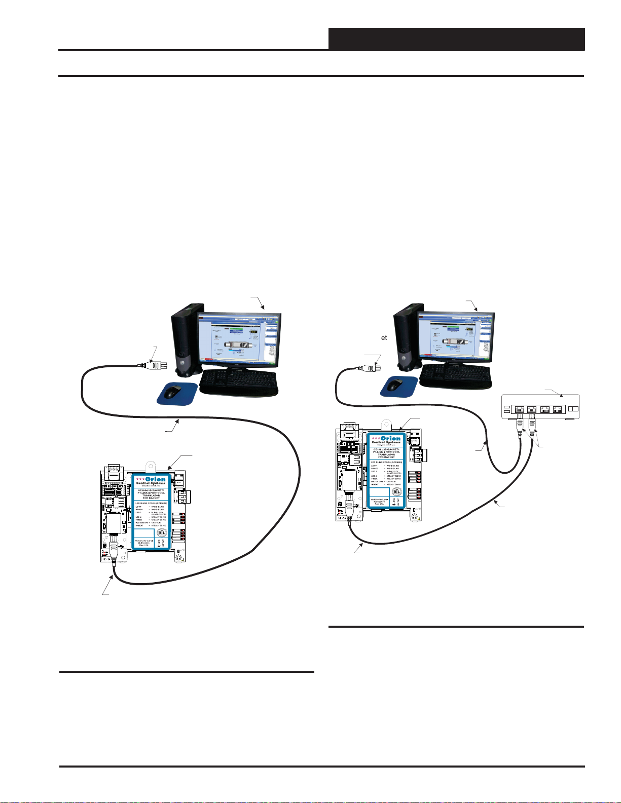
3. PT-LINK CONFIGURATION
Ethernet Cable
Ethernet Hub
Or Switch
Connect Ethernet
Cable To
Ethernet
Connect
Ethernet
Cables To
Ethernet Hub
Ports
1
2
3
4
Ethernet Cable
Connect Ethernet
Crossover Cable
To PT-Link Ethernet
Port
PT-Link BACnet
485
DRIVER
COMM
R
SH
T
LOOP
PROTO
LED1
LED2
TIMER
W_DOG
H-BEAT
POWER
MADE IN USA
Computer
1
2
34567
8
O
N
O
N
1
2
3
4
ON
RSGND
5308
1210
5308
IAEZH004
Made in USA
3.2 PT-Link II Ethernet Connection
You have two options for connecting the PT-Link II to your PC via
Ethernet:
1.) You may connect the PT-Link II directly to your PC by
using a standard CAT5 or crossover cable (by others) as
shown. See Figure 4 for details.
2.) You can also connect both your PC and the PT-Link II to
an Ethernet Hub or Ethernet Switch with standard CAT5
cables. See Figure 5 for details.
Computer
Connect Ethernet
Crossover Cable Directly
To PC Ethernet Card Port
Locate a CA T5 cable and plug one end into your computer’s Ethernet port.
If connecting directly, plug the other end of the Cable into the Ethernet
port on the PT -Link II. If connecting through an Ethernet Hub or Switch,
plug the other end of the PC cable into the hub, and use a second CAT5
cable to connect the PT-Link II to the hub as well.
Power up the PT-Link II by plugging in the power cable. The PT-Link
II may take up to three minutes to power up completely. Once the PTLink II is powered up, you should notice that the RUN LED is blinking
continuously on the ProtoCessor Board. See Figure 28, page 23 for a
diagram showing the location of the ProtoCessor RUN LED.
Ethernet Crossover Cable
PT-Link BACnet
IAEZH004
Made in USA
RSGND
1210
ON
O
O
N
N
4
2
2
3
34567
8
1
1
5308
5308
Connect Ethernet
Crossover Cable
To PT-Link Ethernet
Port
Figure 4: Connecting With Crossover Cable
485
DRIVER
COMM
R
SH
T
LOOP
PROTO
LED1
LED2
TIMER
W_DOG
H-BEAT
POWER
MADE IN USA
Figure 5: Connecting With Ethernet Cable & Hub
PT-Link II BACnet3 Interface
9
Page 10
3. PT-LINK CONFIGURATION
3.3 IP Address Confi guration
3.3.1 Computer IP Address Set-up for
Windows XP, Vista, 7 & 8
In order for the PT -Link II to communicate properly, it is imperative to
set the IP address of both the PT-Link II as well as the computer to be
within the same netmask. You need to change the IP address on your
computer. The following instructions will explain how to con fi gure the IP
address for Microsoft® Windows XP, V ista, 7, and 8 operating systems.
3.3.1.1 Computer IP Address Set-up for
Windows NT & XP
1.) Click <start>; then click <Control Panel>.
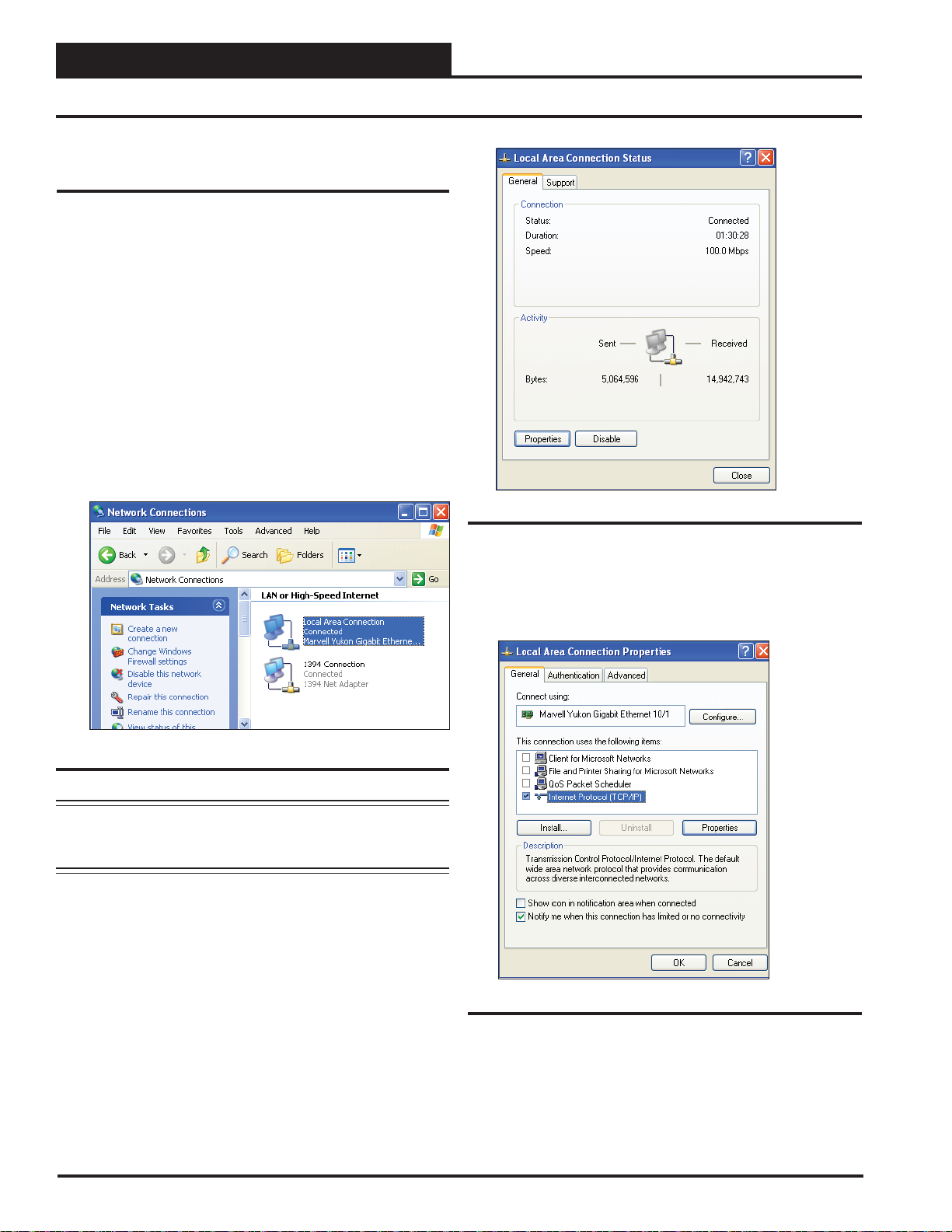
2.) Double-click on the Network Connections icon.
The Network Connections Window will appear (Figure 6).
Zone
Zone
Figure 6: Network Connections Window
NOTE: If any wireless connections are listed, disable them
by right-clicking the connection and selecting
<Disable>.
3.) In the Network Connections Window, double-click the
Local Area Connections entry. The Local Area Connection
Status Window will appear (Figure 7).
Figure 7: Local Area Connection Status Window
4.) As shown in Figure 7, click <Properties> in the lower
left of the window. The Local Area Connection Properties
Window will appear.
10
Figure 8: Local Area Connection Properties Window
5). As shown in Figure 8, in the Connection Items list box,
be sure the Internet Protocol (TCP/IP) is checked. Select the
Internet Protocol (TCP/IP) item to highlight it and then click
<Properties>. The Internet Protocol Properties Window will
appear.
PT-Link II BACnet3 Interface
Page 11
3. PT-LINK CONFIGURATION
3.3 IP Address Confi guration
3.3.1.2 Computer IP Address Set-up for
Windows Vista, 7 & 8
1.) Click <start>; then click <Control Panel> (Vista &
Windows 7). Click <start>; then right-click for <All apps>.
Click <All apps> and then click <Control Panel>
(Windows 8).
2.) Click on the Network and Internet icon.
3.) Click Network and Sharing Center.
4.) From the shaded box in the left side of the window, select
Manage Network Connections (Vista) or Change adapter
settings (Windows 7).
5.) Right-click on the Local Area Connection icon and select
<Properties> for the drop down window.
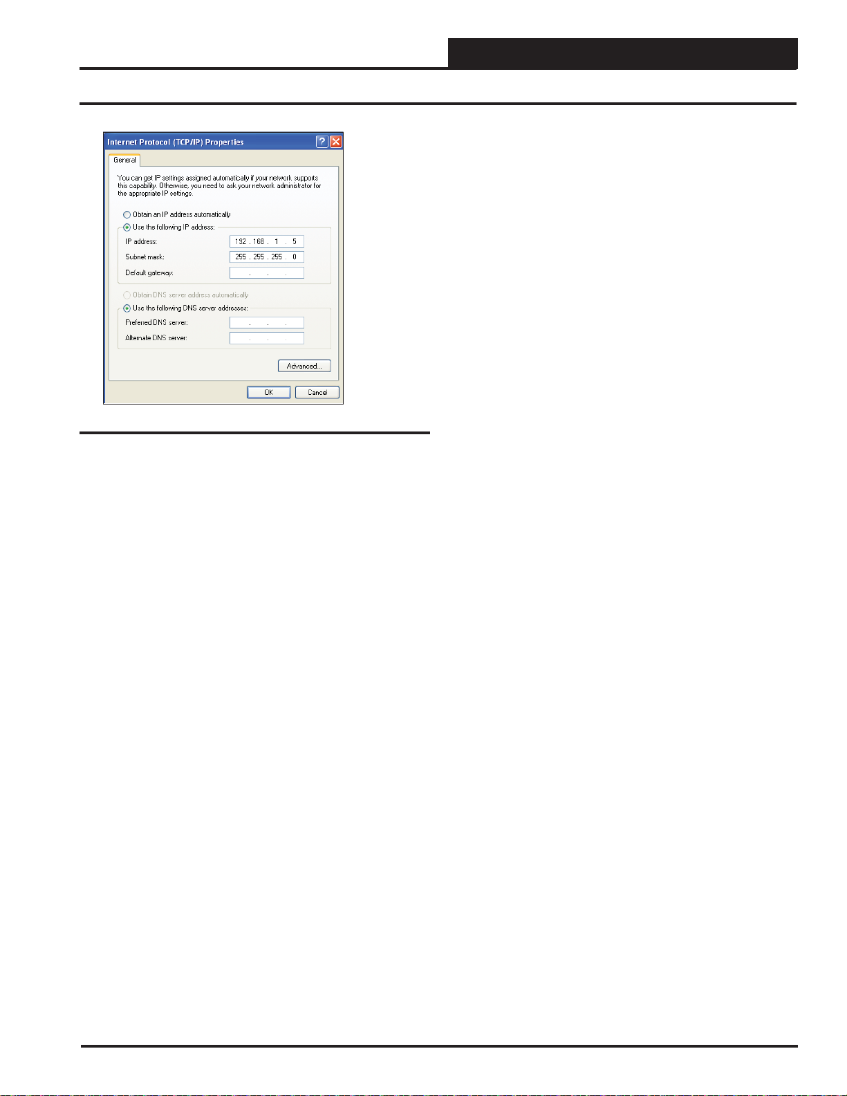
Figure 9: Internet Protocol Properties Window
6). Select the radio button in front of Use the following
IP address (Figure 9) and write down the current defaults
so that you can re-enter them when you fi nish confi guring
the PT-Link and then type in the following
information:
a.) IP address 192.168.1.5
b.) Subnet mask 255.255.255.0
c.) Default Gateway is blank
7.) Click <OK> until all of the above network confi guration
windows are closed. You may have to reboot the computer
before the new values are valid.
6.) Choose Internet Protocol Version 4 (TCP/IPv4) by
highlighting it and then click <Properties>. The Internet
Protocol Properties Window will appear (Figure 9).
7.) Select the radio button in front of Use the following
IP address (Figure 9) and write down the current defaults
so that you can re-enter them when you fi nish confi guring
the PT-Link and then type in the following
information:
a.) IP address 192.168.1.5
b.) Subnet mask 255.255.255.0
c.) Default Gateway is blank
8.) Click <OK> until all of the above network confi guration
windows are closed. You may have to reboot the computer
before the new values are valid.
PT-Link II BACnet3 Interface
11
Page 12
3. PT-LINK CONFIGURATION
3.3 IP Address Confi guration
3.3.2 BACnet MS/TP - Setting Node_
Offset to Assign Specifi c Device
Instances
After setting your PC to be on the same subnet as the PT-Link,
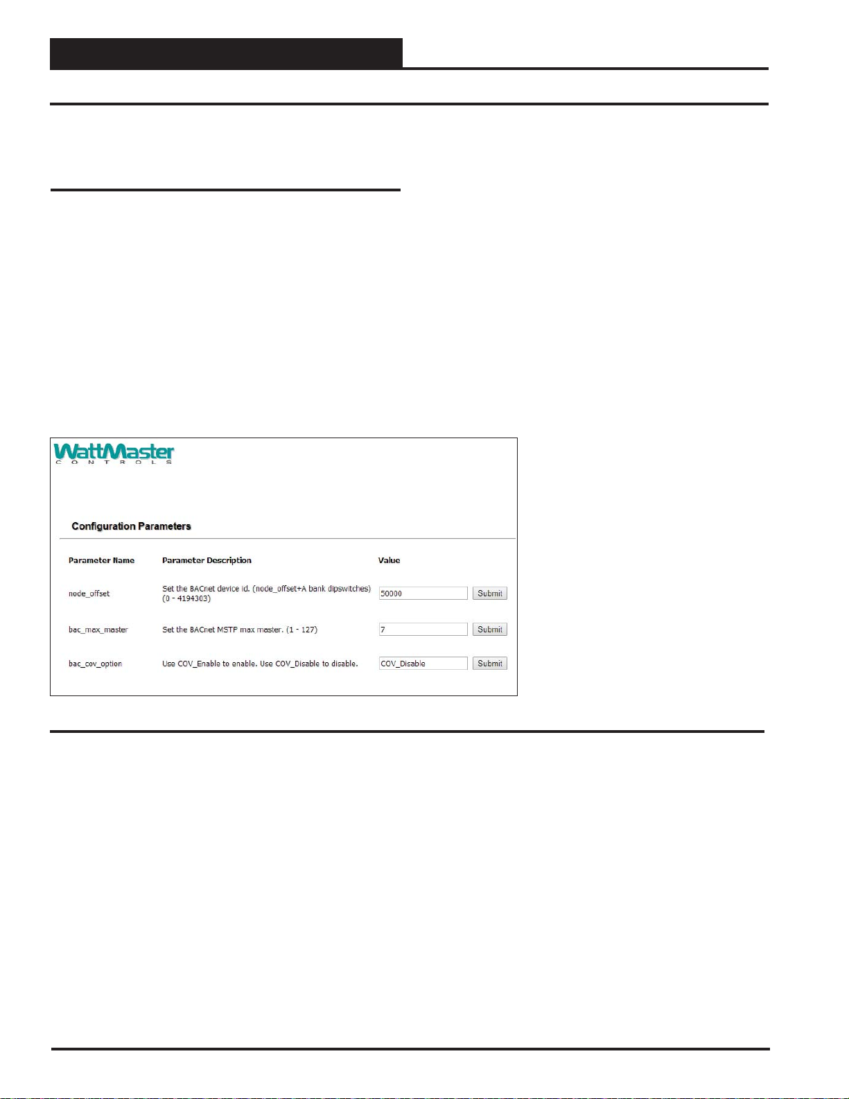
open a web browser on your PC and enter the IP address of
the PT-Link; the default address is 192.168.1.24. (Figure 10).
1. If the IP address of the PT-Link has been changed by previous
confi guration, you will need to get the assigned IP address from the
network administrator or use the FieldServer ToolBox to fi nd the
IP Address.
2. The confi guration page will be displayed as your landing page.
(Figure 10)
3. The node offset can be changed on the confi guration page.
Zone
Zone
Figure 10: BACnet MS/TP Settings for Node_Offset
4. The Node_Offset fi eld will be presented displaying the current
value (default = 50,000).
5. Change the value of Node_Offset to establish the desired Device
Instance value, and click <Submit>.
Device Instance = Node_Offset +
A bank DIP switch setting
(A1-A7)
12
PT-Link II BACnet3 Interface
Page 13
3. PT-LINK CONFIGURATION
3.4 Changing the Confi g.csv File
NOTE: You may need Administration rights to perform this
function. See the Password Section, page 65.
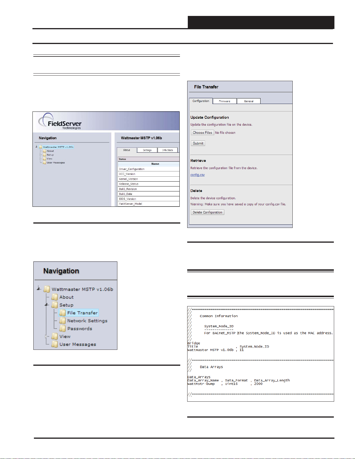
1.) Open your web browser, and type the IP Address of the PT-Link,
which defaults to <192.168.1.24>, and press <ENTER>. The GUI
will launch. See Figure 11.
Figure 11: The FS-GUI Main Screen
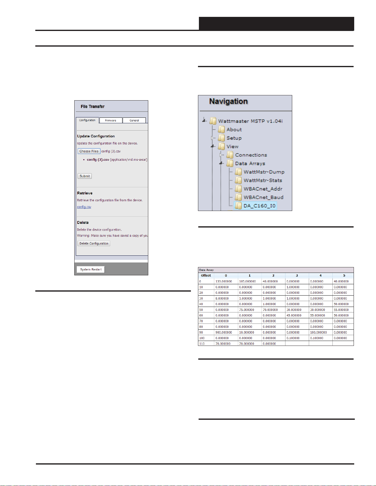
3.) Refer to the File Transfer Window below (Figure 13). In the Con-
fi guration Tab, under Retrieve, click the confi g.csv fi le in order to save
it to a destination and then open it.
2.) In the Navigation Window on the left of the FS-GUI Screen, click
<Setup> and then click <File Transfer>. See Figure 12.
Figure 12: Navigation Window - File Transfer
Figure 13: File Transfer - Confi guration Tab
4.) Open the confi g.csv fi le in Notepad. See Figure 14.
WARNING: Only edit the confi g.csv fi le using Notepad. DO
NOT use Excel. Using Excel to edit the confi g.csv fi le will
corrupt its contents!
PT-Link II BACnet3 Interface
Figure 14: Confi g.csv File
13
Page 14
3. PT-LINK CONFIGURATION
3.4 Changing the Confi g.csv File
Zone
Zone
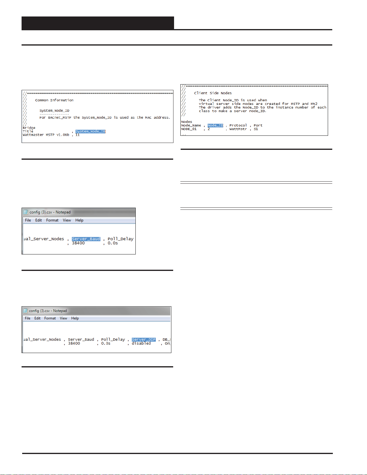
5.) Near the top of the text fi le under ‘System_Node_ID’, change the
BACnet MAC address from the default of 11 (Figure 15). You can
obtain this address to enter from your Building Automation System
(BAS) Integrator.
Figure 15: System Node ID
6.) If you need to change the server baud rate, under ‘Connections’,
change the Server_Baud (Figure 16). Possible Baud Rate values are
(9600, 19200, 38400, and 76800). The default Baud Rate is 38400. You
can obtain the correct baud rate from your BAS Integrator.
8.) The last change you may need to make is the Node_ID under ‘Client
Side Nodes’ which is the BACnet Device Instance Number (Figure 18).
The default is 1.Y ou can obtain the Node ID from your BAS Integrator.
Figure 18: Client Node ID
9.) Once all changes have been made to the text fi le, while still in
Notepad, click <File> in the upper left and then click <Save>. Now
close the fi le and return to the FS-GUI Screen open in your browser.
NOTE: Do not rename the fi le. The fi le must always be named
“confi g.csv”; otherwise, it will be ignored by the PT-
Link.
Figure 16: Server Baud Rate
7.) Inside the text fi le under ‘Connections’, change the ‘Server_DIP’
parameter from ‘Enabled’ to ‘Disabled’. (See Figure 17).
Figure 17: Server Dip Switch
14
PT-Link II BACnet3 Interface
Page 15
3. PT-LINK CONFIGURATION
3.4 Changing the Confi g.csv File
10.) In the File Transfer Window under Update Confi guration, click
<Choose Files> or <Browse>and locate the confi g.csv fi le you just
saved. Then click <Submit>. See Figure 19. Wait until the message,
“Confi guration update complete” appears and then click the <System
Restart> button at the bottom of the File Transfer W indow to activate
the new confi guration fi le.
3.4.1 Verifying Communications
1. ) In the Navigation Window on the left of the FS-GUI Main Screen,
click
<View> and then click <Data Arrays>. See Figure 20.
Figure 20: Navigation Window - View Data Arrays
Figure 19: Update Confi guration
NOTE: The following fi les can also be udpated in File Transfer W indow:
Firmware Files: The FieldServer Firmware contains the application
program commonly referred to as the DCC or the PCC. This program
contains the protocol drivers applicable to the application and the FieldServer Operating System Kernel. A Firmware update is only required
when updated fi les are received from FieldServer support. Firmware
fi les have a *.bin extension. The procedure for updating these is the
same as for the confi guration fi les, but the update needs to be made in
the Firmware Tab.
General (Other) Files: Other fi les that can be updated include the FS-
GUI image and other fi les described in driver manuals. The procedure for
updating these is the same as for the confi guration fi les, but the update
needs to be made in the General Tab.
2. ) Click on the Controller name. In this case, it is DA_C160_I0, a
VCM-X Controller. The Controller’s Data Array Table will display.
See Figure 21.
Figure 21: VCM-X Data Array Table
3 ) You can now cross reference the values shown in Figure 21 with
the listed parameter names in the appropriate Data Array Table for your
controller type. These tables can be found on pages 28-31.
3.4.2 FS-GUI Reference Guide
PT-Link II BACnet3 Interface
An FS-GUI Reference Guide can be found in Section 8, page 64.
15
Page 16
4. UPDATING THE SOFTWARE
4.1 Updating the PT-Link II Controller
Zone
Zone
4.1.1 Programming the PT-Link II with
BootLoader
The PT-Link II is equipped with the ability to update its software with
the use of a computer. You will need the following before you begin:
• PT-Link II in need of an update (powered up,
no other connections necessary)
• Computer running Microsoft Windows
system
TM
operating
• Prism 2 software from www.orioncontrols.com
• Latest version of PT-Link II software (e-mailed from our
tech support staff or downloaded from any of our websites)
and software sheet
• USB Driver Setup.exe fi le from PT-Link II CD or
downloaded from any of our websites.
• USB cable
Follow these simple steps to update the PT-Link II:
1.) Turn on your computer and download the latest Prism 2 software
from www.orioncontrols.com.
2.) Either download the PT -Link II update fi le from http://techsupport.
wattmaster.com or save the fi le to your computer from the e-mail you
received from Tech Support. Record the path and name of the fi le for
later use. Also, print the software sheet provided for future reference.
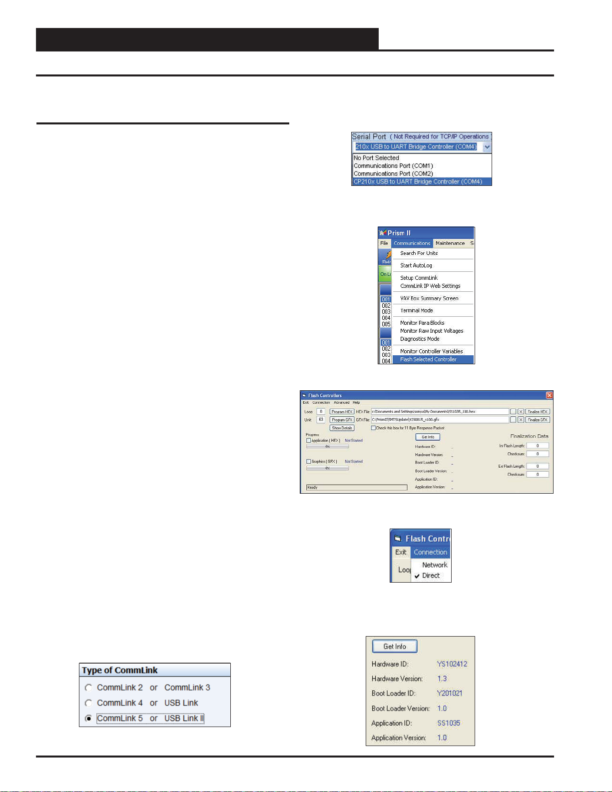
8.) In the Job-Sites Window, from the Serial Port drop down list, select
the correct COM port. If you don’t know the COM port number or if
the number is 10 or higher, follow the directions on pages 18 and 19.
9.) From Prism 2’s Communications tab, select “Flash Selected
Controller.”
10.) The Flash Controller Window will appear.
3.) Run the USB Driver Setup.exe fi le (found on the PT-Link II CD or
downloaded from any of our websites) so that Prism can communicate
to the PT Link II. Unzip the fi le to the directory where you saved your
PT-Link II software.
4.) Plug the USB cable into the computer’s and PT-Link II’s USB
ports.
5.) A message will pop-up from the lower menu bar of Windows that
reads, “Found New Hardware.” Click on this message and follow the
instructions that appear to install the USB drivers.
6.) Open Prism 2 and Login with the User Name, admin and the Password, admin. If successful, “Administrator Access” will appear at the
lower right of the Prism program. NOTE: If using a Prism 2 version
prior to 4.0, the Login is fl ash. If successful, “Level 4 Access” will ap-
pear at the lower right of the Prism program.
7.) Click on the <Job-Site> icon. The Job-Sites Window will appear. In the Type of CommLink Dialog Box, select “CommLink 5.”
11.) From the Flash Controller Window’s Connection tab, select
“Direct”. Keep the Flash Controller Window open.
12.) Cycle power to the PT-Link II and within 5 seconds, click the
<Get Info> button in the Flash Controller W indow. The PT-Link II in-
formation will now appear in the window under the <Get Info> button.
16
PT-Link II BACnet3 Interface
Page 17
4. UPDATING THE SOFTWARE
4.1 Updating the PT-Link II Controller
13.) The Application ID should be SS1035 and the Application V ersion
should match the software version you will be updating to.
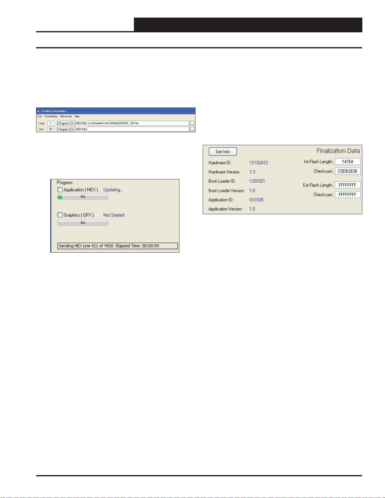
14.) In the HEX File fi eld, enter the path and name of the HEX fi le you
downloaded and/or copied to your hard drive. Use the Browse button
(...) to the right of the fi eld if you need help in locating the fi le.
15.) Now, cycle power to the PT-Link II once again and within 5
seconds click on the <Program HEX> button (shown above). If successful, you should see the Progress Application HEX bar showing the
progress percentage.
16.) When the bar shows 100% completed, verify the PT-Link II’s
software is running by observing the Timer LED blinking.
17.) Verify the PT -Link II’ s Application Version by once again cycling
power to the PT-Link II and within 5 seconds clicking the <Get Info>
button.
18.) Verify all fi elds are correct in the information below the <Get
Info> button and under “Finalization Data.” The “Int Flash Length”
and “Checksum” values should match the values provided with the
software sheet.
PT-Link II BACnet3 Interface
17
Page 18
4. UPDATING THE SOFTWARE
4.1 Updating the PT-Link II Controller
Zone
Zone
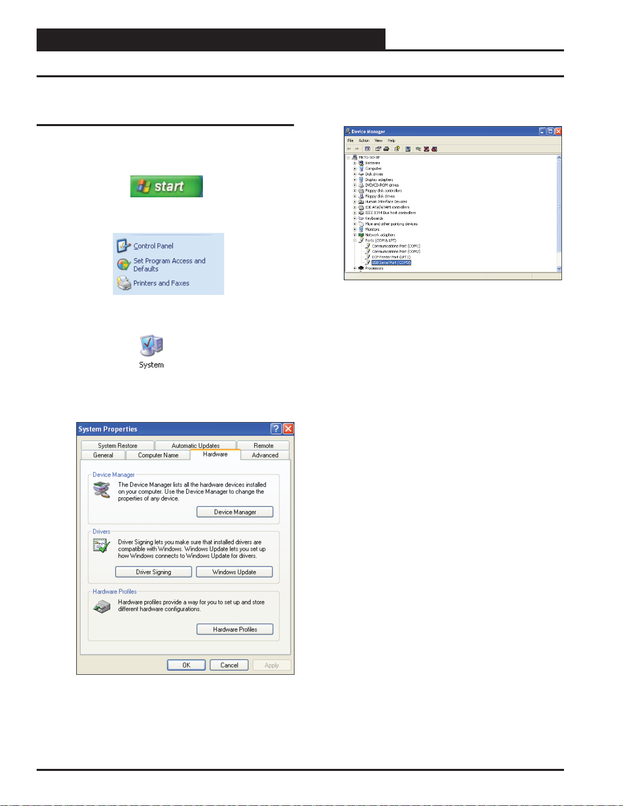
4.1.2 Finding What COM Port Number
the PT-Link II is Using
1. Left-click on <Start>, located on the bottom
left of the Windows Tool Bar.
2. Select <Control Panel>.
3. Double-click the System Icon.
6. Click on the plus sign next to Ports to see all of the
common ports.
7. Locate the USB Serial Port (COM#). The COM# in
parentheses is the port it is located on. Write this COM
port number down. You will need to know this when
setting up the Prism software.
8. If the COM port number is 10 or greater, go to
“Changing the USB COM Port Number” on page 19.
4. Click the <Hardware> tab.
18
5. Click the <Device Manager> button.
PT-Link II BACnet3 Interface
Page 19
4. UPDATING THE SOFTWARE
4.1 Updating the PT-Link II Controller
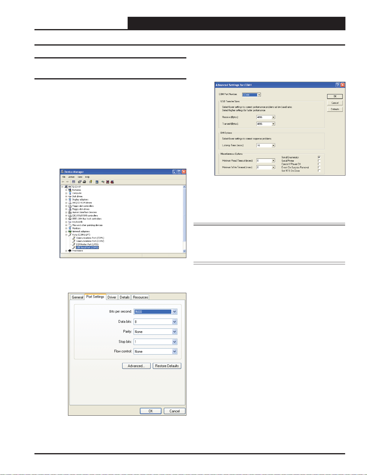
4.1.3 Changing the USB COM Port
Number
When the PT-Link II is fi rst plugged in, it will be assigned a COM port
number to be used for communicating with the Prism software. If the
port number is 10 or greater, it needs to be changed to a value less than
10 to be recognized by Prism.
1. Click <Start>, click <Control Panel>, click
<System>, click the <Hardware> tab, and then
click <Device Manager> to get to the Device
Manager Window.
2. Click on the plus sign next to Ports to see all of the
COM ports.
4. To assign a port number less than 10, click on
<Advanced>. The Advanced Settings Window
will appear.
5. In the COM Port Number drop box, select which
COM port you wish to use. Make sure you select a
COM port number that is not currently in use (you can
see the ports in use in the Device Manager Window).
Select a port that is less than 10.
NOTE: Windows
that has ever been installed on your computer. So if
there are no available ports below 10, choose a port
number less than 10 for a device listed that you know
you are not currently using.
®
will assign a port number to every device
3. Right-click on “USB Serial Port (COM#)” and select
<Properties>. In the Properties Window, select the
<Port Settings> tab.
6. Once you select the correct COM port number, click
<OK> and close any windows opened in the process
of changing the port number. Make note of this number
because you will need it for your Prism setup.
PT-Link II BACnet3 Interface
19
Page 20
Zone
Zone
4. UPDATING THE SOFTWARE
4.2 Updating the Field Server Software
Zone
Zone
1.) Extract and save the update fi le you receive from Field Server onto
your PC.
2.) Open your web browser, and type the IP Address of the PT-Link,
which defaults to <192.168.1.24>, and press <ENTER>. The GUI
will launch. Click <Diagnostic and Debugging>. The Main Screen
will appear. See Figure 22.
Figure 22: The FS-GUI Main Screen
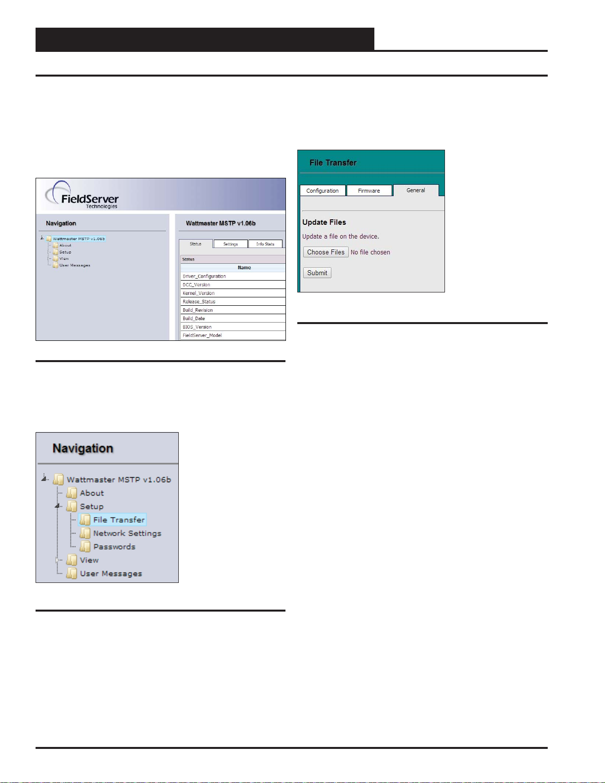
4.) Refer to the File Transfer W indow below (Figure 24). In the General
Tab, click <Browse> and locate the fi le you saved in Step 1. Then click
on <Submit>. When the download is complete, click on the <System
Restart> button.
Figure 24: File Transfer - General Tab
3.) In the Navigation Window on the left of the FS-GUI Screen, click
<Setup> and then click <File Transfer>. See Figure 23.
Figure 23: Navigation Window - File Transfer
20
PT-Link II BACnet3 Interface
Page 21
5. TROUBLESHOOTING
5.1 Troubleshooting Communications
5.1.1 Check Wiring and Settings
No COMS on WattMaster side
If TX/RX are not fl ashing rapidly, then there is a COM issue on the
WattMaster side and you need to check the following things:
• Visual observations of LEDs on ProtoNode.
(Figure 28, page 23)
• Check baud rate, parity, data bits, stop bits
• Check WattMaster device address
• Verify wiring
• Verify all the WattMaster devices that were discovered
in FST Web Confi gurator. (page 12)
NOTE: If the problem still exists, a Diagnostic Capture
needs to be taken and sent to W attMaster Technical
Support. See page 26.
Field COM problems
• Visual observations of LEDs on PT-Link. (Figure 27,
page 22)
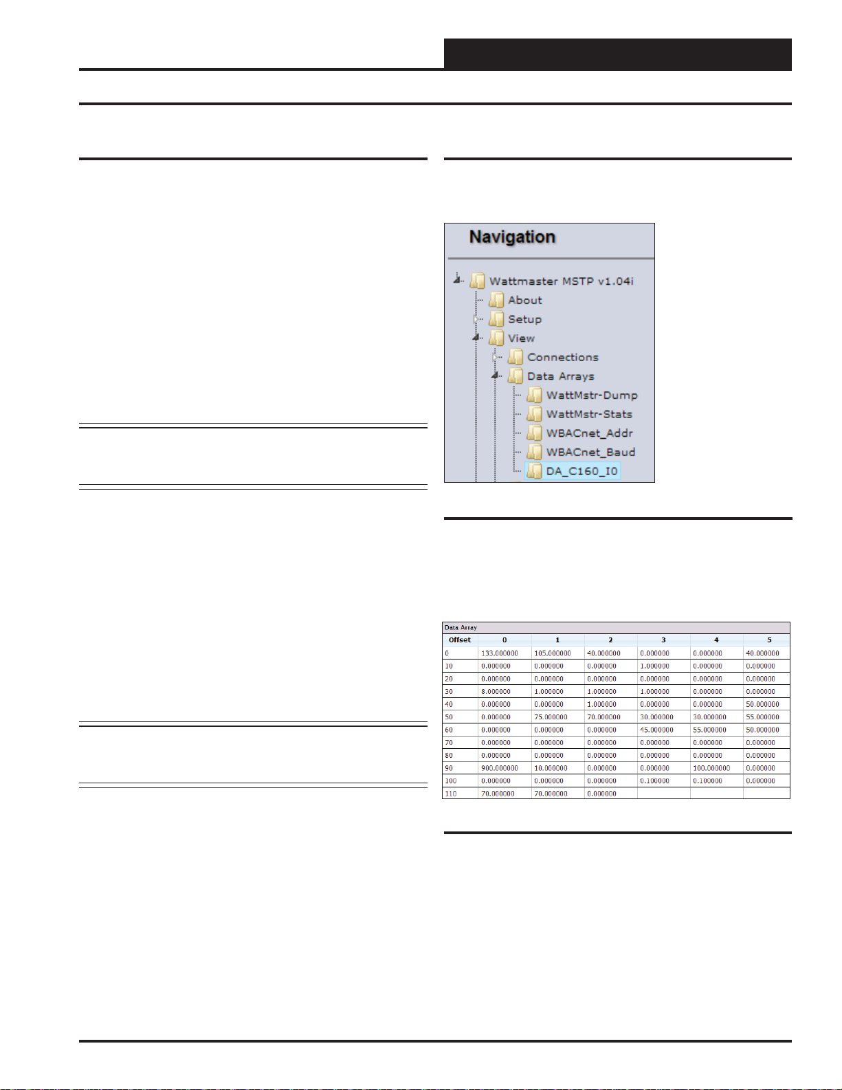
5.1.2 Verifying Communications
1. ) In the Navigation Window on the left of the FS-GUI Main Screen,
click <View> and then click <Data Arrays>. See Figure 25.
Figure 25: Navigation Window - View Data Arrays
2. ) Click on the Controller name. In this case, it is DA_C160_I0, a
VCM-X Controller. The Controller’s Data Array Table will display.
See Figure 26.
• Visual dipswitch settings (using correct baud rate and
device instance)
• Verify IP address setting
• Verify wiring
NOTE: If the problem still exists, a Diagnostic Capture
needs to be taken and sent to W attMaster Technical
Support. See page 26.
Figure 26: VCM-X Data Array Table
3 ) You can now cross reference the values shown in Figure 26 with
the listed parameter names in the appropriate Data Array Table for your
controller type. These tables can be found on pages 28-31.
PT-Link II BACnet3 Interface
21
Page 22
5. TROUBLESHOOTING
5.2 Troubleshooting LEDs
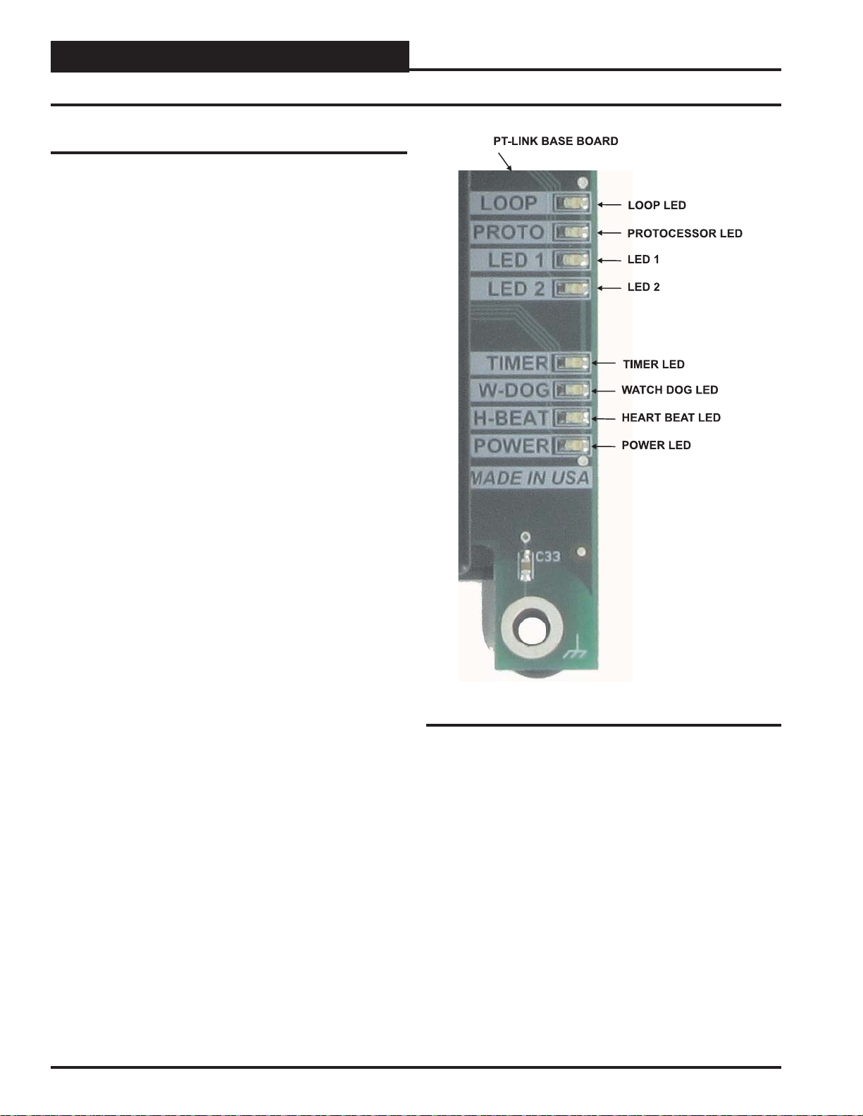
5.2.1 PT-Link II Board LEDs
The PT-Link II BACnet® is equipped with LEDs that can be used for
troubleshooting. There are eight LEDs on the PT -Link board. See Figure
27 for the locations of the LEDs on the PT -Link board. The LED descriptions and functions are listed in the following paragraphs.
POWER LED
When the PT-Link II BACnet® is powered up, the “POWER” LED
should light up and stay on continuously. If it does not light up, check
to be sure that you have 24 VAC connected to the board, that the wiring
connections are tight, and that they are wired for correct polarity. The 24
V AC power must be connected so that all ground wires remain common.
If after making all these checks the “POWER” LED still does not light
up, please contact WattMaster Controls Technical Support at our Toll
Free number—866-918-1100—for assistance.
LOOP LED
When power is applied to the PT-Link II BACnet®, the “LOOP” LED
will also light up. The LED should fl icker rapidly, indicating that the
PT-Link is trying to communicate with the controllers on the loop. A
“fl icker” is defi ned as a brief moment when the LED turns off and
back on. If the “LOOP” LED does not operate as indicated above, fi rst
power down the unit and then reapply power. If this does not work,
please contact WattMaster Controls Technical Support at our Toll Free
number—866-918-1100—for assistance.
Zone
Zone
LED 1
When power is fi rst applied, “LED 1” will be off temporarily and then
will blink one time for each controller it is communicating with. For
example, if you have 4 controllers on the loop connected to the PT -Link,
“LED 1” will blink 4 times. If the amount of blinks does not match the
number of controllers connected to the loop, it indicates there is a communications problem. The best way to fi nd out which board is not com-
municating is to go to each controller and look at its “COMM” LED. The
“COMM” LED should be solid and will fl icker occasionally indicating
communication with the PT-Link II BACnet®. If the “COMM” LED
does not fl icker, there is no communication with that controller.
LED 2
When power is fi rst applied, “LED 2” will be off temporarily and then
will blink slowly indicating that the PT -Link baseboard is communicating
with the ProtoCessor Module. If “LED 2” does not blink, check that the
ProtoCessor Module is installed correctly on the PT -Link baseboard and
that the “PWR” LED is lit up on the ProtoCessor Module.
PROTO LED
When the PT-Link II is fi rst powered up, the “PROTO” LED should
blink rapidly and may appear to be on solid. This LED verifi es com-
munication with the board and the ProtoCessor. If the LED doesn’t
light up, check that the ProtoCessor is installed correctly and fi rmly
connected to the Base Board. The “PWR” LED should also be lit on
the ProtoCessor Module.
Figure 27: PT-Link II BACNET® LED Locations
WATCH DOG LED
The “W-DOG” LED is used for troubleshooting by W attMaster Controls
Technical Support. The “W-DOG” LED should always be on solid.
HEARTBEAT LED
The “H-BEAT” LED blinks to show the PT-Link II board software is
running. If the LED doesn’t light up, and all other checks have been
made, please contact W attMaster Controls T echnical Support at our T oll
Free number—866-918-1100—for assistance.
TIMER LED
The “TIMER” LED is used for troubleshooting by W attMaster Controls
Technical Support. The “TIMER” LED should always be blinking
steadily.
22
PT-Link II BACnet3 Interface
Page 23

5. TROUBLESHOOTING
5.2 Troubleshooting LEDS
5.2.2 PT-Link Module LEDs
Refer to Figure 28 for LED locations.
PWR LED
When the PT -Link II is fi rst powered up, the “PWR” green LED should
light up and stay on continuously. If the LED doesn’t light up, check
that the ProtoCessor is installed correctly and fi rmly connected to the
Base Board.
RX & TX LEDs
During normal operation, the “RX” LED will fl ash when a message is
received on the fi eld port of the ProtoCessor and the “TX” LED will
fl ash when a message is sent on the fi eld port of the ProtoCessor The
“TX” and “RX” LEDs work together to indicate that communication
is being established with the desired protocol network. If both LEDs
are blinking, then communication is working properly. If not, check
the protocol network wiring and the baud rate in the confi guration fi le.
RUN LED
Upon powerup, the “RUN” LED should light up and stay solid for 15
seconds. It should then blink steadily, signifying normal operation. The
Protocessor will be able to access RUINET once this LED starts fl ashing.
RUN2 LED
The “RUN2” LED should blink steadily after power up, signifying
normal operation. The Protocessor will be able to access RUINET once
this LED starts fl ashing.
SYS ERR LED
The “SYS ERR” LED will go on solid 15 seconds after power up and
then shut off. A steady red light will indicate there is a system error on
the ProtoCessor. If this occurs, immediately report the related “system
error” shown in the error screen of the Remote User Interface to FieldServer Technologies for evaluation.
NODE OFFLINE LED
The “NODE OFFLINE” amber LED will go on solid 15 seconds after
power up and then shut off. A steady amber light indicates the ProtoCessor is not communicating with a device that it is polling.
Figure 28: PT-Link II BACnet3® LED Locations
NOTE: If all of these tests are made and the controller still doesn’t
operate, please contact W attMaster Controls T echnical
Support at our T oll Free number—866-918-1100—for
assistance.
Figure 29: PT-Link II BACnet3® Components
PT-Link II BACnet3 Interface
23
Page 24

Zone
5. TROUBLESHOOTING
5.3 Troubleshooting the PT-Link Controller
Zone
5.3.1 Addressing WattMaster Devices
in a BACnet® Network
Each PT-Link II BACnet® generates only one BACnet® device regardless of the number of W attMaster controls connected to it. This
device will have all the properties of all the WattMaster controls
connected. The instance of the device is equal to the unit address. The
properties of each control can be differentiated by an offset of 500.
Examples:
1.) Properties of the controller address as 1 will range
from 0 to 499.
2.) Properties of the controller address as 2 will range
from 500 to 999.
3.) Properties of the controller address as 3 will range
from 1000 to 1499.
To search for the instance of a specifi c property, follow the next
formula:
Property Instance = ((Controller Address – 1) * 500) + Instance
Number from table.
Example:
5.3.2 CAS BACnet Explorer for Validating PT-Link in the Field
Sierra Monitor Corporation has arranged a complimentary 2-week
fully functional copy of CAS BACnet Explorer (through Chipkin
Automation) that can be used to validate BACnet MS/TP communications of PT-Link in the fi eld without having to have the BMS
Integrator on site. A Serial or USB to RS-485 converter is needed
to test BACnet MS/TP.
5.3.2.1 Downloading the CAS Explorer
and Requesting an Activation Key
To request the complementary BACnet CAS key, go to http://app.
chipkin.com/activation/twoweek/ and fi ll in all of the information.
See Figure 30. Enter Vendor Code “WattMaster2BACnet”. Once
completed, the email address that was submitted will be registered.
1.) The PT-Link II BACnet® has a Node ID equal to fi ve.
2.) Two VCM controllers connected and addressed to one
and four.
3.) Searching for the Outdoor Temperature of each
controller.
4.) Instance of the Outdoor Temperature in the VCM table
equal to AI: 54.
5.) Client will only see Device 5.
6.) Under Device 5 it will see AI: 54 for the Outdoor
Temperature of the unit addressed as 1 and AI: 1554
for the Outdoor Temperature of the unit addressed as 4.
NOTE: To simplify the calculation, we recommend that the
WattMaster controllers be addressed in sequential
order from one to the last controller without any
unused address(es) in between.
Figure 30: Requesting a Two-Week Trial
24
PT-Link II BACnet3 Interface
Page 25

5. TROUBLESHOOTING
5.3 Troubleshooting the PT-Link Controller
Go to the website http://www.chipkin.com/technical-resources/
cas-bacnet-explorer/, and download and install the CAS BACnet
Explorer to your PC.
Open CAS BACnet Explorer. In the CAS Activation form, enter
the email address that was registered, and click on “Request a key”.
The CAS key will then be emailed to the registered address. Cut/
paste the key from the email into the Product key fi eld and click
<Activate>. See Figure 31.
5.3.2.2 CAS BACnet MS/TP Setup
1. Using the Serial or USB to RS-485 converter, connect it to your
PC and the 3 Pin BACnet MS/TP connector on PT-Link FPC-N34.
2. Open CAS Explorer.
3. Click on
4. Check the BACnet MS/TP box and uncheck the BACnet/IP and
BACnet Ethernet boxes
5. Set the BACnet MS/TP MAC address to 0.
6. Set the BACnet MS/TP Baud Rate to 38400.
7. Click
8. On the bottom right-hand corner, make sure that the BACnet
MS/TP box is green
9. Click on discover.
10. Check all 4 boxes.
11. Click <Send>.
<Settings>.
<Ok>.
5.3.3.1 Viewing Diagnostic Information
Figure 31: Requesting an Activation Key
1. T ype the IP address of the PT-Link into your web browser or use
the FieldServer Toolbox to connect to the PT-Link
2. Click on
and then click on <Connections>. See Figure 32.
3. If there are any errors showing in the Connections Window, please
refer to Section 5.1.1, page 21 for the relevant wiring and settings.
<Diagnostics and Debugging> then click on <View>,
Figure 32: Connections Window
PT-Link II BACnet3 Interface
25
Page 26

5. TROUBLESHOOTING
5.4 FieldServer Diagnostic Utilities
Zone
Zone
5.4.1 Diagnostic Capture Procedures
1. Once the Diagnostic Capture is complete, email it to
support@protocessor.com. The Diagnostic Capture will
allow us to rapidly diagnose the problem.
2. Ensure that FieldServer Toolbox is Loaded on the PC
that is currently being used, or download FieldServer Toolbox.zip at http://www.protocessor.com/tech-support/
utilities-and-design-documents.php
3. Extract the executable fi le and complete the installation.
4. Disable any wireless Ethernet adapters on the
PC/Laptop. See Figure 33.
5. Disable fi rewall and virus protection software if
possible.
6. Connect a standard Cat 5 Ethernet cable between the PC
and ProtoNode.
7. Double-click on the FS Toolbox Utility.
8. Click on the diagnose icon of the desired device.
See Figure 34.
Figure 33: Ethernet Port Location
Figure 34: FieldServer Toolbox - Diagnostic Icon
26
PT-Link II BACnet3 Interface
Page 27

5. TROUBLESHOOTING
5.4 FieldServer Diagnostic Utilities
9. Select Full Diagnostic. See Figure 35.
Figure 35: Full Diagnostic
10. If desired, the default capture period can be changed.
See Figure 36.
11. Click on
<Start Diagnostic>. Figure 36.
11. Wait for the Capture period to fi nish. The Diagnostic
Test Complete Window will appear. Figure 37.
Figure 37: Diagnostic Test Complete Window
12. Once the Diagnostic test is complete, a .zip fi le will be
saved on the PC.
13. Click
to launch explorer and have it point directly at the
correct folder.
14. Send the Diagnostic zip fi le to support@fi eldserver.com.
<Open> in the Diagnostic Test Complete Window
Figure 36: Set Capture Period and Start Diagnostic
PT-Link II BACnet3 Interface
27
Page 28

Zone
6. DATA ARRAYS
Zone
6.1 VCB-X & VCM-X Modular Data Arrays
VCB-X Modular Data Array For Field Server
Offset 0 1 2 3 4 5 6 7 8 9
0
10
20
30
40
50
60
70
80
90
100
110
120
130
140
150
160
170
AppVer ClSt HtSt SpcTp SaTp OaTp UnitMode CtrlSts ClEnbl HtEnbl
EcoEnbl FanDly OnRlys EcoPos VfdBwPos AlmSts AlmGrp1 AlmGrp2 AlmGrp3 SaTpAlm
OaTpAlm SpcTpAlm MchClAlm MchHtAlm PofAlm DrtFlAlm SmokeAlm LoSaAlm HiSaAlm CtrlTpCF
CtrlTpHF CtrlTp InRh InRhStM MdClPos MdHtPos OcpClSt OcpHtSt UnClOst UnHtOst
SaClSt SaHtSt SpcTpOst SaTpOst OaTpOst SchdFrc OnRly1 OnRly2 OnRly3 OnRly4
OnRly5 OnRly6 MnExRly1 MnExRly2 MnExRly3 MnExRly4 MnExRly5 RlExRly1 RlExRly2 RlExRly3
RlExRly4 RlExRly5 RlExRly6 RlExRly7 RlExRly8 RlExRly9 RlExRly10 RlExRly11 RlExRly12 MinEcoSt
OaCFM EtCFM SaCFM FrcHvacM FrcFanSp FrcEcono SaTpStM RaTp OaRh StaticPr
CO2 BuildPr EtFnSpd CoilTp RaCFM HeadPr RtVlvPos LvWtrTp MdGsVPos HeadPrSt
CdCtrSg1 OaClSt OaHtSt WmupTg RhDewpSt EcoEnbSt RaTpOst ColTpOft LWAmbnt PreHtAmb
C02MinLv C02MaxLv InRhSt StatPrSt RfPrSt OACfmMin HiInRh ClHdPrSt HtHdPrSt LoClTpSt
HiClTpSt SaClRt SaHtRt ClLoRt ClHiRt HtLoRt HtHiRt CtrlMod DschgTp OaWtbl
OaDewPt SucPr CoilTpSt RetBydmp RaDmp RaRH SldAdOfs MdSelDb ClStgWdw HtStgWdw
MchClLkt MchHtLkt LoSaCf HiSaCf DfrSt LvH2OOst CO2Ost CTpHiAlm CTpLoAlm HpLkt
VFDClMin VFDHtMin VFDVtMin MaxEcoHt MaxEcoCO HpDfrInt AptDfr DuctPfDb RlfPrDb OaCfmDb
SZVAVFnI SaWmupSt SaCldnSt RehtEnbl EmHtEnbl RaTpAlm MisEM1 ColPfAlm CO2Alm DschgAlm
OaCfmAlm ExtCmSr SaCfmSr RaCfmSr MisMHGRV MisMDGAS Mis12Rly HiCtrlMd LoCtrlMd DigCmpCf
DigCmpLk HiHedPr H2OProf LoSucPr HiSucPr – – – – –
Table 3: VCB-X Modular Data Array For Field Server
VCM-X Modular Data Array For Field Server
Offset 0 1 2 3 4 5 6 7 8 9
0
10
20
30
40
50
60
70
80
90
100
110
120
AppVer ClSt HtSt OaWtbl TpDmnd SpcTp SaTp RaTp OaTp DuctPr
OaRh UnitMode CtrlSts ClEnbl HtEnbl EcoEnbl FanDly PofCfg CO2Cfg MdHt2Ins
Rt2Ins OnRlys ExRlys12 ExRlys34 EcoPos VfdBwPos VfdExPos AlmSts AlmGrp1 AlmGrp2
AlmGrp3 SaTpAlm OaTpAlm SpcTpAlm MchClAlm MchHtAlm PofAlm DrtFAlm SmokeAlm LoSaAlm
HiSaAlm CtrlTpCF CtrlTpHF CtrlTp InRh InRhStM DptStM MdClPos MdHtPos MdHt2Pos
Rt2Pos OcpClSt OcpHtSt UnClOst UnHtOst WtblSt SaClSt SaHtSt WmupSt SpcTpOst
SaTpOst RaTpOst OaTpOst CoilTpSt DptSt InRhSt DuctPrSt RfPrSt SchdFrc OnRly1
OnRly2 OnRly3 OnRly4 OnRly5 ExRly1 ExRly2 ExRly3 ExRly4 ExRly5 ExRly6
ExRly7 ExRly8 ExRly9 ExRly10 ExRly11 ExRly12 ExRly13 ExRly14 ExRly15 ExRly16
CO2St MinEcoSt CO2Level ByPasDmp RaDmp RfPr OaDwpt CoilTp SaTpStM PreHtSp
OaCFM EtCFM SaCFM OACfmSt OACfmRs OACfmStM MdCmp2 HdPr1 HdPr2 CdFan1
CdFan2 RmVFDPos SaClRt SaHtRt ClLoRt ClHiRt HtLoRt HtHiRt T24EcFb T24TpAlm
T24NEWS T24EWISN T24DpAlm T24ExsOA RaTpAlm AlmGrp5 HdPr22 HdPr22 CdFan21 CdFan22
Table 4: VCM-X Modular Data Array For Field Server
28
PT-Link II BACnet3 Interface
Page 29

6. DATA ARRAYS
6.2 VCM-X WSHP Coil & VCM-X WSHP Tulsa / RNE Data Arrays
VCM-X WSHP (Tulsa) & RNE Data Array For Field Server
Offset 0 1 2 3 4 5 6 7 8 9
0
10
20
30
40
50
60
70
80
90
100
110
120
130
140
AppVer ClSt HtSt OaWtbl TpDmnd SpcTp SaTp RaTp OaTp DuctPr
OaRh UnitMode CtrlSts ClEnbl HtEnbl EcoEnbl FanDly PofCfg CO2Cfg MdHt2Ins
Rt2Ins OnRlys ExRlys12 ExRlys34 EcoPos VfdBwPos VfdExPos AlmSts AlmGrp1 AlmGrp2
AlmGrp3 SaTpAlm OaTpAlm SpcTpAlm MchClAlm MchHtAlm PofAlm DrtFAlm SmokeAlm LoSaAlm
HiSaAlm CtrlTpCF CtrlTpHF CtrlTp InRh InRhStM DptStM MdClPos MdHtPos MdHt2Pos
Rt2Pos OcpClSt OcpHtSt UnClOst UnHtOst WtblSt SaClSt SaHtSt WmupSt SpcTpOst
SaTpOst RaTpOst OaTpOst CoilTpSt DptSt InRhSt DuctPrSt RfPrSt SchdFrc OnRly1
OnRly2 OnRly3 OnRly4 OnRly5 ExRly1 ExRly2 ExRly3 ExRly4 ExRly5 ExRly6
ExRly7 ExRly8 ExRly9 ExRly10 ExRly11 ExRly12 ExRly13 ExRly14 ExRly15 ExRly16
CO2St MinEcoSt CO2Level ByPasDmp RaDmp RfPr OaDwpt CoilTp SaTpStM PreHtSp
OaCFM EtCFM SaCFM OACfmSt OACfmRs OACfmStM MdCmp2 HdPr1 HdPr2 CdFan1
CdFan2 WaterTpA WaterTpB A1LSPAlm A1LktAlm A2LSPAlm A2LktAlm B1LSPAlm B1LktAlm B2LSPAlm
B2LktAlm LWT1Alm LWT2Alm POWF1Alm POWF2Alm ComMAlm RmVFDPos SaClRt SaHtRt ClLoRt
ClHiRt HtLoRt HtHiRt T24EcFb T24TpAlm T24NEWS T24EWISN T24DpAlm T24ExsOA RaTpAlm
AlmGrp5 HdPr22 HdPr22 CdFan21 CdFan22 – – – – –
Table 5: VCM-X WSHP (Tulsa) / RNE Data Array For Field Server
VCM-X WSHP (Coil) Data Array For Field Server
Offset 0 1 2 3 4 5 6 7 8 9
0
10
20
30
40
50
60
70
80
90
100
110
120
130
AppVer ClSt HtSt OaWtbl TpDmnd SpcTp SaTp RaTp OaTp DuctPr
OaRh UnitMode CtrlSts ClEnbl HtEnbl EcoEnbl FanDly PofCfg CO2Cfg MdHt2Ins
Rt2Ins OnRlys ExRlys12 ExRlys34 EcoPos VfdBwPos VfdExPos AlmSts AlmGrp1 AlmGrp2
AlmGrp3 SaTpAlm OaTpAlm SpcTpAlm MchClAlm MchHtAlm PofAlm DrtFAlm SmokeAlm LoSaAlm
HiSaAlm CtrlTpCF CtrlTpHF CtrlTp InRh InRhStM DptStM MdClPos MdHtPos MdHt2Pos
Rt2Pos OcpClSt OcpHtSt UnClOst UnHtOst WtblSt SaClSt SaHtSt WmupSt SpcTpOst
SaTpOst RaTpOst OaTpOst CoilTpSt DptSt InRhSt DuctPrSt RfPrSt SchdFrc OnRly1
OnRly2 OnRly3 OnRly4 OnRly5 ExRly1 ExRly2 ExRly3 ExRly4 ExRly5 ExRly6
ExRly7 ExRly8 ExRly9 ExRly10 ExRly11 ExRly12 ExRly13 ExRly14 ExRly15 ExRly16
CO2St MinEcoSt CO2Level ByPasDmp RaDmp RfPr OaDwpt CoilTp SaTpStM PreHtSp
OaCFM EtCFM SaCFM OACfmSt OACfmRs OACfmStM MdCmp2 HdPr1 HdPr2 CdFan1
CdFan2 WaterTpA A1LSPAlm A1LktAlm B1LSPAlm B1LktAlm LWT1Alm POWF1Alm ComMAlm RmVFDPos
SaClRt SaHtRt ClLoRt ClHiRt HtLoRt HtHiRt T24EcFb T24TpAlm T24NEWS T24EWISN
T24DpAlm T24ExsOA RaTpAlm – – – – – – –
Table 6: VCM-X WSHP (Coil) Data Array For Field Server
PT-Link II BACnet3 Interface
29
Page 30

Zone
6. DATA ARRAYS
Zone
6.3 VCM-X & SA Data Arrays
VCM-X Data Array For Field Server
Offset 0 1 2 3 4 5 6 7 8 9
0
10
20
30
40
50
60
70
80
90
100
110
AppVer ClSt HtSt OaWtbl TpDmnd SpcTp SaTp RaTp OaTp DuctPr
OaRh UnitMode CtrlSts ClEnbl HtEnbl EcoEnbl FanDly PofCfg CO2Cfg MdHt2Ins
Rt2Ins OnRlys ExRlys12 ExRlys34 EcoPos VfdBwPos VfdExPos AlmSts AlmGrp1 AlmGrp2
AlmGrp3 SaTpAlm OaTpAlm SpcTpAlm MchClAlm MchHtAlm PofAlm DrtFAlm SmokeAlm LoSaAlm
HiSaAlm CtrlTpCF CtrlTpHF CtrlTp InRh InRhStM DptStM MdClPos MdHtPos MdHt2Pos
Rt2Pos OcpClSt OcpHtSt UnClOst UnHtOst WtblSt SaClSt SaHtSt WmupSt SpcTpOst
SaTpOst RaTpOst OaTpOst CoilTpSt DptSt InRhSt DuctPrSt RfPrSt SchdFrc OnRly1
OnRly2 OnRly3 OnRly4 OnRly5 ExRly1 ExRly2 ExRly3 ExRly4 ExRly5 ExRly6
ExRly7 ExRly8 ExRly9 ExRly10 ExRly11 ExRly12 ExRly13 ExRly14 ExRly15 ExRly16
CO2St MinEcoSt CO2Level ByPasDmp RaDmp RfPr OaDwpt CoilTp SaTpStM PreHtSp
OaCFM EtCFM SaCFM OACfmSt OACfmRs OACfmStM SaClRt SaHtRt ClLoRt ClHiRt
HtLoRt HtHiRt – – – – – – – –
Table 7: VCM-X Data Array For Field Server
SA Controller Data Array For Field Server
Offset 0 1 2 3 4 5 6 7 8 9
0
10
20
30
40
50
60
70
80
90
AppVer ClSt HtSt TpDmnd SpcTp SaTp DuctPr UnitMode CtrlSts ClEnbl
HtEnbl EcoEnbl FanDly MdHt2Ins Rt2Ins EcoPos VfdBwPos SaTpAlm SpcTpAlm MchClAlm
MchHtAlm PofAlm DrtFAlm LoSaAlm HiSaAlm CtrlTpCF CtrlTpHF CtrlTp InRh InRhStM
DptStM MdClPos MdHtPos MdHt2Pos Rt2Pos OcpClSt OcpHtSt UnClOst UnHtOst SaClSt
SaHtSt WmupSt SpcTpOst SaTpOst CoilTpSt DptSt InRhSt DuctPrSt SchdFrc OnRly1
OnRly2 OnRly3 OnRly4 OnRly5 ExRly1 ExRly2 ExRly3 ExRly4 ExRly5 ExRly6
ExRly7 ExRly8 ExRly9 ExRly10 ExRly11 ExRly12 ExRly13 ExRly14 ExRly15 ExRly16
CoilTp SaTpStM PreHtSp EaTp EwTp EaRH HdPr1 HdPr2 CoilTp2 EaDpt
WSEByp WSEByp2 MdCmp2 CoilTpSt CdPos1 CdPos2 EaTpAlm EmerAlm PoWFAlm DrnAlm
EaTpOst EwTpOst SaClRt SaHtRt ClLoRt ClHiRt HtLoRt HtHiRt – –
Table 8: SA Controller Data Array For Field Server
30
PT-Link II BACnet3 Interface
Page 31

6. DATA ARRAYS
6.4 VCM Data Array
VCM Data Array For Field Server
Offset 0 1 2 3 4 5 6 7 8 9
0
10
20
30
40
50
60
70
80
90
100
Table 9: VCM Data Array For Field Server
AppVer ClSt HtSt OaWtbl TpDmnd SpcTp SaTp RaTp OaTp DuctPr
OaRh UnitMode CtrlSts ClDmnd HtDmnd DehmDmnd ClEnbl HtEnbl EcoEnbl FanDly
WmupDmnd PofCfg CO2Cfg MdHt2Ins Rt2Ins OnRlys ExRlys12 ExRlys34 EcoPos VfdBwPos
VfdExPos AlmSts AlmGrp1 AlmGrp2 AlmGrp3 SaTpAlm OaTpAlm SpcTpAlm MchClAlm MchHtAlm
PofAlm DrtFlAlm SmokeAlm LoSaAlm HiSaAlm CtrlTpCF CtrlTpHF CtrlTp InRh InRhStM
DptStM MdClPos MdHtPos MdHt2Pos Rt2Pos OcpClSt OcpHtSt UnClOst UnHtOst WtblSt
SaClSt SaHtSt WmupSt SpcTpOst SaTpOst RaTpOst OaTpOst CoilTpSt DptSt InRhSt
DuctPrSt RfPrSt SchdFrc OnRly1 OnRly2 OnRly3 OnRly4 OnRly5 ExRly1 ExRly2
ExRly3 ExRly4 ExRly5 ExRly6 ExRly7 ExRly8 ExRly9 ExRly10 ExRly11 ExRly12
ExRly13 ExRly14 ExRly15 ExRly16 CO2St MinEcoSt CO2Level ByPasDmp RaDmp RfPr
OaDwpt CoilTp SaTpStM PreHtSp – – – – – –
PT-Link II BACnet3 Interface
31
Page 32

7. PARAMETER TABLES
7.1 VCB-X BACnet Parameters
Zone
Zone
NOTE: When using Celsius scaling, all temperature values will
need to be divided by 10 by the BMS to properly read
the status and setpoint values, e.g., a value of 200º C
needs to be divided by 10 for an actual value of 20º C.
BACnet Properties for the VCB-X Controller
Param-
eter
Bad or
Missing 12
Relay
Expansion
Board.
Alarm
Group 1
Alarm
Group 2
Alarm
Group 3
Alarm
Status
Application
Software
Version
Unit Mode UnitMode AI:123 See Unit Mode
Building
Pressure
Building
Pressure
Setpoint
Building
Pressure
Control
Deadband
CO
2
CO
2
Sensor
Calibration
Deadband
Offset
Name Object Description
Mis12Rly BI: 376 The 12 Relay
Expansion Board
is confi gured but
not detected.
AlmGrp1 AI: 104 See Alarm
AlmGrp2 AI: 105 See Alarm
AlmGrp3 AI: 106 See Alarm
AlmSts AI: 1 Indicates that
there is an alarm.
AppVer AI: 99 Current version
of the software
in the unit.
BuildPr AI:272 Current value of
the Building
Pressure Sensor.
RfPrSt AV:118 Current Building
Pressure
Setpoint.
RfPrDb AV:358 Value above
and below the
Building Pres-
sure Setpoint
where no control
change occurs.
CO2 AI:271 Current CO2
Level.
CO2Ost AV: 348 If the CO2
Sensor is reading
incorrectly, you
can use this
option to enter
an offset value
to adjust the
Sensor’s CO2
reading.
Limits
Group Bits on
page 43.
Group Bits on
page 43.
Group Bits on
page 43.
0 = Off
1 = On
See Alarm
Group Bits on
page 43.
Bits on page
43.
-.20 .20
.01 0.1
-500
ppm
500
ppm
BACnet Properties for the VCB-X Controller
Param-
eter
CO
2
Minimum
Setpoint
CO
2
Maximum
Setpoint
Bad CO
Sensor
Coil
Tempera-
ture
Coil
Tempera-
ture Offset
Bad Coil
Pressure
Sensor
Coil Tem-
perature
Setpoint
Name Object Description
CO2MinLv AV:287 This is the
CO2
MaxLv
CO2Alm BI: 368 Failure of the
2
CoilTp AI: 181 Current coil
ColTpOft AV:284 If the Coil
ColPrAlm BI: 367 Failure of the
CoilTpSt AI: 334 This is the
AV:288 This is the CO2
threshold CO
level at which
the Economizer
begin to be reset
level at which
the Economizer
be reset to the
Economizer Max
Position in High
CO2 . In between
Max CO2 levels
the Economizer
Position will be
proportionally
reset between the
confi gured Min
Damper Position
Position in High
Sensor is reading
incorrectly, use
this offset to adjust the Sensor’s
Coil Pressure
Sensor. W ill shut
calculated Coil
Dehumidifi cation
Min Damper
Position
Setpoint will
higher.
Min Damper
Position will
the Min and
Min Damper
and the Max
CO2 .
CO2 Sensor.
temperature
reading.
Temperature
Temperature.
unit down.
current
Suction
Temperature
target during
Mode.
Limits
0 2000
2
0 2000
-100 100
32
PT-Link II BACnet3 Interface
Page 33

7. PARAMETER TABLES
7.1 VCB-X BACnet Parameters
BACnet Properties for the VCB-X Controller
Param-
eter
Low Coil
Temperature
Setpoint
Limit
High Coil
Temperature
Setpoint
Limit
Com-
pressor
Discharge
Tempera-
ture
Bad Com-
pressor
Discharge
Sensor
Control
Mode
Name Object Description
LoClTpSt AV:295 This is the low-
est that the Coil
Temperature will
be reset to during
Space Humid-
ity Reset of the
Coil Suction
Temperature
Setpoint. If no
coil temperature
reset is required,
this value should
be set the same
as the High Coil
Temperature
Setpoint.
HiClTpSt AV:296 This is the high-
est that the Coil
Temperature will
be reset to during
Space Humid-
ity Reset of the
Coil Suction
Temperature
Setpoint. If no
coil temperature
reset is required,
this value should
be set the same
as the Low Coil
Temperature
Setpoint.
DschgTp AI: 331 Current value of
the Compressor
Discharge T em-
perature Sensor.
DschgAlm BI: 369 Failure of the
Digital Compres-
sor Discharge
Temperature
Sensor.
CtrlMod AI: 97 1=Constant
Limits
35 70
35 70
Volume
2=Supply Air
Cooling Only
3=Outdoor
Temp Control
4=Single Zone
VAV
5=Supply Air
Tempering
6=Space Temp
Control w/
High OA
Content
Unoccupied
BACnet Properties for the VCB-X Controller
Param-
eter
Control
Tem-
perature
Cooling
Failure
Control
Tem-
perature
Heating
Failure
High
Control
Mode
Tempera-
ture
Low Control Mode
Tempera-
ture
Cooling
Low Reset
Source
Name Object Description
CtrlTpCF BI: 108 Activated if the
control tempera-
ture does not get
within 5°F to the
occupied cooling
setpoint in an
hour in the cool-
ing mode. This
alarm is not used
in 100% outside
air units or sup-
ply air control.
CtrlTpHF BI: 109 Activated if the
control tempera-
ture does not get
within 5°F to the
occupied heating
setpoint in an
hour in the heat-
ing mode. This
alarm is not used
in 100% outside
air units or sup-
ply air control.
HiCtrlMd BI: 377 Occurs when the
Controlling Sen-
sor Temperature
rises above the
Cooling Mode
Enable Setpoint
plus the Control
Mode High
Alarm Offset.
Applies only to
Space or Return
Air Temperature
controlled units.
LoCtrlMd BI: 378 Occurs when the
Controlling Sensor Temperature
falls below the
Heating Mode
Enable Setpoint
minus the Con-
trol Mode Low
Alarm Offset.
Applies only to
Space or Return
Air Temperature
controlled units.
ClLoRt AV: 326 If doing Supply
Air Setpoint
Reset, this is
the Low Reset
Source value in
Cooling that will
correspond to
the Supply Air
Cool High Reset
Setpoint.
Limits
1 150
PT-Link II BACnet3 Interface
33
Page 34

7. PARAMETER TABLES
7.1 VCB-X BACnet Parameters
Zone
Zone
BACnet Properties for the VCB-X Controller
Param-
eter
Cooling
High Reset
Source
Condenser
Control
Signal
Controlling
Sensor
High
Alarm
Offset
Controlling
Sensor
Low Alarm
Offset
Control
Status
Control
Tempera-
ture
Cooling
Enabled
Name Object Description
ClHiRt AV: 327 If doing Supply
Air Setpoint
Reset, this is
the High Reset
Source value in
Cooling that will
correspond to
the Supply Air
Cooling Setpoint
(Low Reset).
CdCtrSg1 AI:280 Condenser Fan
Signal 1 Status.
CTpHiAlm AV: 349 If the tem-
perature of the
controlling sen-
sor rises above
the Occupied
Cooling Setpoint
by this value,
a High Control
Temp Alarm
will occur. Only
applies if confi g-
ured for Space
or Return Air
Temp Control, or
as Single Zone
VAV.
CTpLoAlm AV: 350 If the tempera-
ture of the con-
trolling sensor
falls below the
Occupied Heat-
ing Setpoint by
this value, a Low
Control Temp
Alarm will oc-
cur. Only applies
if confi gured for
Space or Return
Air Temp Con-
trol, or as Single
Zone VAV.
CtrlSts AI: 4 Current
operational
status.
CtrlTp AI: 9 Current value of
the control
temperature
sensor.
ClEnbl AI: 6 Status that
indicates
mechanical
cooling is
enabled to
operate.
Limits
1 150
050
050
See Control
Status Bits on
page 43.
BACnet Properties for the VCB-X Controller
Param-
eter
Mechani-
cal Cooling
Lockout
Mechani-
cal Cooling
Alarm
Cooling
Setpoint
Mirror
Cool
Staging
Window
Adaptive
Defrost
Interval
Adjust-
ment
Dewpoint
Setpoint
Name Object Description
MchClLkt AV: 342 The VCB-X
will Lockout
Mechanical
Cooling when
the Outdoor Air
Temperature
is below this
Setpoint.
MchClAlm BI: 94 Compressor Re-
lays are enabled
but the Supply
Air Temperature
has not fallen
5°F within a
user-adjustable
time period. This
does not apply
for Modulating
Cooling.
ClSt AI: 7 Occupied
Cooling Mode
Enable
Setpoint.
ClStgWdw AV: 340 In Cooling
Mode, if the
Supply Air
Temperature
drops below the
Active Supply
Air Cooling
Setpoint minus
this Staging Win-
dow, a Cooling
Stage will be
deactivated after
its Minimum
Run Time.
AptDfr AV: 356 Adjustment to
the Heat Pump
Defrost Interval
depending on
whether the
Defrost Mode
lasts 10 minutes
or less than 10
minutes.
RhDewpSt AV:282 On a MUA unit,
if the outdoor
dewpoint rises
above this
setpoint, the unit
will
activate Dehu-
midifi cation.
Limits
-30 100
130
0 Min 30
Min
35 80
34
PT-Link II BACnet3 Interface
Page 35

7. PARAMETER TABLES
7.1 VCB-X BACnet Parameters
BACnet Properties for the VCB-X Controller
0% 100%
0% 100%
2
Limits
-30 80
Param-
eter
Digital
Compres-
sor Cutoff
Digital
Com-
pressor
Lockout
Dirty Filter
Alarm
Economiz-
er Enabled
Economiz-
er Enable
Setpoint
Economiz-
er Position
Max
Economiz-
er in Heat
Mode
Max
Econo-
mizer in
High CO2
Mode
Minimum
Econo-
mizer
Position
Name Object Description
DigCmpCf BI: 379 Occurs if the
DigCmpLk BI: 380 Occurs if fi ve
DrtFlAlm BI: 96 Alarm that
EcoEnbl AI: 15 Status that
EcoEnbSt AV:283 The economizer
EcoPos AI: 16 Current position
MaxEcoHt AV: 353 Max position
MaxEcoCO AV: 354 The maximum
MinEcoSt AV: 151 Minimum
digital compres-
sor discharge
temperature rises
above 268°F
or the sensor
is shorted. The
compressor is
disabled.
Digital Compres-
sor Cutoffs
occur within
four hours. The
compressor will
be locked out.
indicates the
fi lters are dirty.
indicates the
economizer is
enabled.
is enabled if the
outdoor drybulb,
dewpoint, or
wetbulb temperature falls below
this setpoint.
of the econo-
mizer damper.
the Economizer
Damper can
open in the Heat-
ing Mode. Takes
priority over
Max Position in
High CO
Economizer
Minimum Posi-
tion can be reset
up to during CO
position of the
economizer in
the occupied
value the
override.
mode.
.
2
0 100
BACnet Properties for the VCB-X Controller
Param-
eter
Force
Econo-
mizer
Emergency
Heat
Enabled
Exhaust
Fan CFM
Missing
Exhaust
CFM
Sensor
Exhaust
Fan Speed
Missing
EM1
Expansion
Module
Fan
Starting
Delay
Leaving
H2O
Offset
Water
Proof
of Flow
Failure
Name Object Description
FrcEcono AV: 267 Overrides all
EmHtEnbl BI: 364 Shows the Emer-
EtCFM
ExtCfmSr BI: 371 Indicates that the
EtFnSpd AI: 273 Current value of
MisEM1 BI: 366 Indicates that the
FanDly AI: 25 Indicates the
LvH2OOst AV: 347 If the Leaving
H2OProf BI: 382 Indicates no
AI:194 Current Exhaust
other Outdoor
Air Damper
position com-
mands so as to
maintain this
fi xed position.
Confi guring
for “Auto” will
restore normal
unit control of
the Outdoor Air
Damper/Econo-
mizer operation.
gency Heat is
enabled based on
the Compressor
Heating Lockout.
Airfl ow
Measurement
Exhaust CFM
Sensor is not
detected.
the VFD relief
fan signal.
EM1 Expansion
Module is not
communicating
with the VCB-X
Controller.
current fan status
related to request
to run, fan start-
ing delay or POF
failure.
Water Tempera-
ture Sensor is
reading incorrectly, use this to
enter an offset to
adjust the Sensor’s T empera-
ture.
Proof of Water
Flow.
Limits
0% 100%
Auto=65535
0=No Request
1=Fan
Running
2=Fan Start
Delay
3=POF Failure
-100 100
PT-Link II BACnet3 Interface
35
Page 36

7. PARAMETER TABLES
7.1 VCB-X BACnet Parameters
Zone
Zone
BACnet Properties for the VCB-X Controller
Param-
eter
Force
HVAC
Mode
Head
Pressure
Head
Pressure
Setpoint
Head
Pressure
Setpoint
in Cooling
Mode
Head
Pressure
Setpoint
in Reheat
Mode
High Head
Pressure
SAT
Heating
Low Reset
Source
SAT
Heating
High Reset
Source
Heating
Enabled
Name Object Description
FrcHvacM AV: 262 Overrides
normal controller
operation in
order to force
the unit into this
desired mode.
Confi guring
for “Auto” will
restore normal
unit control of
the mode of
operation.
HeadPr AI:276 Current value of
the Head
Pressure
Reading.
HeadPrSt AI:279 Current Head
Pressure
Setpoint.
ClHdPrSt AV:293 This is the Head
Pressure Setpoint
the unit will
control to in the
Cooling Mode.
HtHdPrSt AV:294 This is the Head
Pressure Setpoint
the unit will
control to in the
Dehumidifi cation
Reheat Mode.
HiHedPr BI: 381 Indicates the
Head Pressure is
too high.
HtLoRt AV: 328 If doing Supply
Air Setpoint
Reset, this is
the Low Reset
Source value in
Heating that will
correspond to the
Supply Air Heat-
ing High Reset
Setpoint.
HtHiRt AV: 329 If doing Supply
Air Setpoint
Reset, this is
the High Reset
Source value in
Cooling that will
correspond to
the Supply Air
Cooling Setpoint
(Low Reset).
HtEnbl AI: 30 Status that
indicates that
mechanical heat-
ing is enabled to
operate.
Limits
0=Auto
1=Vent
2=Cool
3=Heat
4=Vent
Dehum.
5=Cool
Dehum.
6=Heat
Dehum.
240
PSI
240
PSI
1 150
1
420
PSI
420
PSI
150
BACnet Properties for the VCB-X Controller
Param-
eter
Heating
Setpoint
Mirror
Heat
Staging
Window
Mechani-
cal Heating
Lockout
Mechani-
cal Heating
Alarm
Heat Pump
Compres-
sor Heating
Outdoor
Lockout
Heat Pump
Defrost
Interval
Heat
Wheel
Defrost
Setpoint
Indoor
Humidity
Name Object Description
HtSt AI: 31 Occupied
Heating Mode
Enable Setpoint.
HtStgWdw AV: 341 In the Heat-
ing Mode, if
the Supply Air
Temperature
rises above the
Active Supply
Air Heating
Setpoint plus the
Heating Stage
Off Window
value, a Heating
stage will be
deactivated after
its Minimum
Run Time.
MchHtLkt AV: 343 The VCB-X
will Lockout
Mechanical
Heating when
the Outdoor Air
Temperature
is above this
Setpoint.
MchHtAlm BI: 95 Heating Mode
has been initiated
but the Supply
Air Temperature
has not risen
5°F within a
user-adjustable
time period. This
does not apply
for Modulating
Heating.
HpLkt AV: 351 Compressor
Heating will be
locked out when
the Outdoor Air
Temperature
is below this
Setpoint.
HpDfrInt AV: 355 The Heat Pump
Defrost Interval
is the length of
time that must
be met between
Defrost Modes.
Dfrst AV: 346 The unit will go
into Heat Wheel
Defrost Mode
when the Out-
door Air is below
this setpoint.
InRh AI: 67 Current value
of the Indoor
Humidity
Sensor.
Limits
150
-30 150
-30 100
10
Min
050
120
Min
36
PT-Link II BACnet3 Interface
Page 37

7. PARAMETER TABLES
7.1 VCB-X BACnet Parameters
BACnet Properties for the VCB-X Controller
Param-
eter
Indoor
Humidity
Setpoint
High
Indoor
Humidity
Reset
Limit
Indoor
Humidity
Setpoint
Mirror
Leaving
Water
Tempera-
ture
Low
Ambient
Relay
Setpoint
Mode
Select
Deadband
Modulat-
ing
Cooling
Position
Modulat-
ing Gas
Valve
Position
Modulat-
ing
Heating
Position
Name Object Description
InRhSt AV:289 If Coil Temp
HiInRh AV:292 During Coil
InRhStM AI: 114 Mirror of the
LvWtrTp AI:278 Leaving Water
LWAmbnt AV:285 Temperature at
MdSelDb AV: 339 This Setpoint
MdClPos AI: 115 Current position
MdGs
VPos
MdHtPos AI: 116 Current position
AI:274 Current
Reset is being
used this is also
the lowest Space
RH value that
corresponds to
the Hi Coil Temp
Setpoint.
Temp Reset, this
is the highest
Space RH value
that corresponds
to the Low Coil
Temp Setpoint.
InRhSt “read
only.”
Temperature
Value
which the Low
Ambient Relay
will activate in
the Occupied
or Unoccupied
Mode.
is added to and
subtracted from
the HVAC Mode
Setpoints to de-
termine when the
unit enters and
leaves a mode of
operation.
of the modulat-
ing
cooling signal
(Chilled water or
digital
compressor).
position of
MODGAS
modulating gas
valve control.
of the modulat-
ing
heating signal
(hot water or
SCR heat).
Limits
0 100
0 100
-30 70
110
BACnet Properties for the VCB-X Controller
Param-
eter
Missing
MODGAS
Module
Morning
Warm-Up
Return Air
Target
Setpoint
Occupied
Cooling
Setpoint
Occupied
Heating
Setpoint
Hood On
Outdoor
Air
Cooling
Setpoint
Hood On
Outdoor
Air
Heating
Setpoint
Outdoor
Air CFM
Name Object Description
MisMDGAS BI: 375 Alarm that
indicates that
the MODGAS
module is not
communicating
with the VCB-X
Controller.
WmupTg AV:281 If confi gured,
upon entering the
occupied mode,
the Warm-up
Demand will be
activated if the
return air tem-
perature is one
degree below
this setpoint.
OcpClSt AV: 42 If the control
temperature rises
one degree above
this setpoint,
the control will
activate the
cooling demand.
If the control
temperature is
the Supply Air
Sensor, then the
cooling demand
is always active.
OcpHtSt AV: 43 If the control
temperature
drops one degree
below
this setpoint,
the control will
activate the
heating demand.
If the
control
temperature
is the Supply
Air Sensor, then
there is no
heating
demand.
OaClSt AV:45 This is the Cool-
ing Mode Enable
Setpoint used
only in Hood On
Mode.
OaHtSt AV:46 This is the Heat-
ing Mode Enable
Setpoint used
only in Hood On
Mode.
OaCFM AI: 193 Current Outdoor
Airfl ow
Measurement
Limits
50 90
1110
1110
1110
1110
PT-Link II BACnet3 Interface
37
Page 38

7. PARAMETER TABLES
7.1 VCB-X BACnet Parameters
Zone
Zone
BACnet Properties for the VCB-X Controller
Param-
eter
Minimum
Desired
Outdoor
Air CFM
Missing
Outdoor
Air CFM
Sensor
Outdoor
Humidity
Outdoor
Air
Dewpoint
Outdoor
Air Tem-
perature
Outdoor
Air
Tempera-
ture Offset
Minimum
Outside
Air CFM
Deadband
Outdoor
Air Tem-
perature
Sensor
Lost
Outdoor
Wetbulb
Preheat
Relay
Setpoint
Proof
of Flow
Alarm
Name Object Description
OACfmMin AV:291 Minimum Out-
door Airfl ow
CFM Setpoint
OaCfmAlm BI: 370 Indicates
Outdoor Air
CFM Sensor is
not detected.
OaRh AI:52 Current value
of the Outdoor
Humidity
Sensor.
OaDewPt AI: 332 Current calcu-
lated Outdoor
Air Dewpoint.
OaTp AI: 54 Current value
of the
outdoor
temperature
sensor.
OaTpOst AV: 53 If the Outdoor
Temperature
Sensor is reading
incorrectly, use
this to enter an
offset to adjust
the Sensor’s
Temperature.
OacfmDb AV: 359 The Deadband
is used both
above and below
the Outdoor Air
CFM setpoint
to help prevent
hunting.
OaTpAlm BI: 117 Indicates a
failure of the
Outdoor Air
Temperature
Sensor.
OaWtbl AI: 55 Current calcu-
lated value of the
outdoor wetbulb
temperature.
PreHtAmb AV:286 If the Supply Fan
is energized this
is the tempera-
ture at which the
Preheat Relay
will activate.
Operates only
in the Occupied
Mode.
PofAlm BI: 26 Indicates no
Proof of Water
Flow.
Limits
.10K 200K
-100 100
10 1000
-30 70
BACnet Properties for the VCB-X Controller
Param-
eter
Reheat
Enabled
Reheat
Valve
Position
Missing
Reheat
Module
Return Air
CFM
Missing
Return
Air CFM
Sensor
Return Air
Damper
Position
Return Air
Humidity
Return Air
Tempera-
ture
Return Air
Tempera-
ture Sensor
Offset
Bad Return
Air Sensor
Return
Bypass
Damper
Position
Schedule
Force
Current
Slide
Adjust
Offset
Name Object Description
RehtEnbl BI: 363 Modulating
RtVlvPos AI:277 Current position
MisMH-
GRV
RaCFM AI:275 Current Return
RaCfmSr BI: 373 Indicates
RaDmp AI: 336 Current Return
RaRH AI: 337 Current value of
RaTp AI: 64 Current value of
RaTpOst AV: 65 If the Return
RaTpAlm BI: 365 Indicates a failure
RetBydmp AI: 335 Current Return
SchdFrc AV: 66 0 = Auto (uses
SldAdOfs AI: 338 Current Slide
BI: 374 Indicates that the
Hotgas Reheat
Enabled.
of MHGRV
modulating hot
gas reheat valve.
MHGRV Module
is not
communicating
with the VCB-X
Controller.
Airfl ow
Measurement.
that the Return
Air CFM Sensor
is not detected.
Air Damper
position.
the Return Air
Humidity Sensor.
the return tem-
perature sensor.
Temperature
Sensor is reading
incorrectly, use
this to enter an
offset to adjust
the Sensor’s
Temperature.
of the Return Air
Sensor.
Bypass Damper
position.
controller’s
schedule)
1 = Forced
Occupied
2 = Forced
Unoccupied
Adjust Offset
value.
Limits
-100 100
02
38
PT-Link II BACnet3 Interface
Page 39

7. PARAMETER TABLES
7.1 VCB-X BACnet Parameters
BACnet Properties for the VCB-X Controller
Param-
eter
Smoke
Alarm /
Emergency
Shutdown
Space
Tempera-
ture
Space
Tempera-
ture Offset
Space
Tempera-
ture Sensor
Lost
Static
Pressure
Static
Pressure
Setpoint
Static
Pressure
Setpoint
Deadband
Suction
Pressure
High
Suction
Pressure
Alarm
Low
Suction
Pressure
Alarm
Supply Air
CFM
High
Supply Air
Tempera-
ture Alarm
Name Object Description
SmokeAlm BI: 119 Indicates the
SpcTp AI:72 Current value of
SpcTpOst AV:71 If the Space
SpcTpAlm BI: 101 Indicates
StaticPr AI:270 Current Static
StatPrSt AV:290 Current Static
DuctPrDb AV:357 Value above and
SucPr AI: 333 Current Suction
HiSucPr BI: 352 Indicates
LoSucPr BI: 383 Indicates
SaCFM AI:195 Current Supply
HiSaAlm BI: 33 The Supply Air
Smoke sensor
has been acti-
vated. This will
shut down the
unit.
the space tem-
perature sensor.
Temperature
Sensor is reading
incorrectly, use
this option to
enter an offset
to adjust the
Sensor’s
Temperature.
a failure of the
Space Tempera-
ture Sensor.
Pressure.
Pressure
Setpoint.
below the Duct
Static Pressure
Setpoint where
no control
change occurs.
Pressure value.
Suction Pressure
is above the
High Suction
Pressure Cool-
ing (Heating)
Setpoint.
Suction Pressure
is below the Low
Suction Pressure
Cooling (Heat-
ing) Setpoint.
Airfl ow
Measurement.
has risen above
the High SAT
Cutof
f Setpoint.
Heating stages
begin to deacti-
vate and the fan
continues to run.
Limits
-100 100
.10 3.0
.01 0.5
BACnet Properties for the VCB-X Controller
Param-
eter
Low Sup-
ply Air
Tempera-
ture Alarm
Supply Air
Cooling
Setpoint
Supply Air
Cool High
Reset
Supply Air
Heat High
Reset
Supply Air
Heating
Setpoint
Supply Air
Tempera-
ture
Bad
Supply Air
Tempera-
ture Sensor
Low
Supply
Air Temp
Cutoff
High
Supply
Air Temp
Cutoff
Name Object Description
LoSaAlm BI: 37 The Supply Air
has fallen below
the Low SAT
Cutoff Setpoint
and cooling
stages will begin
to deactivate.
If the unit is in
Economizer,
Vent, or Heating
Mode the Supply
Fan will shut off.
SaClSt AV:77 Supply Air Cool-
ing Setpoint. If
Supply Air Reset
is confi gured,
this is the Low
SAT Cooling
Reset Value.
SaClRt AV: 324 If Supply Air Re-
set is confi gured,
this is the High
SAT Cooling
Reset Value.
SaHtRt AV: 325 If Supply Air Re-
set is confi gured,
this is the High
SAT Heating
Reset Value.
SaHtSt AV :78 Supply Air Heat-
ing Setpoint. If
Supply Air Reset
is confi gured,
this is the Low
SAT Heating
Reset Value.
SaTp AI:83 Current value of
the Supply Air
Temperature
Sensor.
SaTpAlm BI: 2 Indicates a fail-
ure of the Supply
Air Temperature
Sensor.
LoSaCf AV: 344 Cooling will be
disabled if the
Supply Air Tem-
perature falls
below this value.
See sequence for
more details.
HiSaCf AV: 345 Heating will be
disabled if the
Supply Air Tem-
perature rises
above this value.
See sequence for
more details.
Limits
30 80
0 100
0 250
40 240
0 100
0
250
PT-Link II BACnet3 Interface
39
Page 40

7. PARAMETER TABLES
7.1 VCB-X BACnet Parameters
Zone
Zone
BACnet Properties for the VCB-X Controller
Param-
eter
Supply Air
Tempera-
ture Offset
Current
Supply Air
Temperature
Setpoint
Cooldown
Mode
Supply Air
Setpoint
Missing
Supply
Air CFM
Sensor
Warmup
Mode
Supply Air
Setpoint
SZ VA V
Integral
Constant
Title 24
Econo-
mizer
Feedback
Title 24
Sensor
Alarm
Title
24 Not
Economiz-
ing When
It Should
Title 24
Economiz-
ing When
It Should
Not
Name Object Description
SaTpOst AV:80 If the Supply Air
Temperature
Sensor is reading
incorrectly, use
this offset to adjust the Sensor’s
Temperature.
SaTpStM AI: 82 Current SAT
Cooling or
Heating
setpoint if there
is no reset
source;
Current calculated SAT
setpoint with
Reset Source.
SaCldnSt AV: 362 Cooling will be
controlled to
this Supply Air
Setpoint during
Cool-Down.
SaCfmSr BI: 372 Indicates the
Supply Air CFM
Sensor is not
detected.
SaWmupSt AV: 361 Heating will be
controlled to
this Supply Air
Setpoint during
Morning Warm-
Up.
SZVAVFnl AV: 360 This is the
Integral Constant
for controlling
the SZ VAV Fan
Speed.
T24EcFb AI: 384 Current position
of feedback from
Economizer
actuator.
T24TpAlm BI: 385 Outside Air
or Supply Air
Temperature
Sensor is shorted
or missing.
T24NEWS BI: 386 Economizer is
enabled but not
following the
desired Econo-
mizer position
commanded.
T24EWISN BI: 387 Economizer is
not enabled but
the feedback
signal indicates
a position more
open than the
minimum.
Limits
-100 100
30 80
40 240
010
BACnet Properties for the VCB-X Controller
Param-
eter
Title 24
Damper
Failure
Title 24
Excess
Outdoor
Air
Unoc-
cupied
Cooling
Offset
Unoc-
cupied
Heating
Offset
VFD
Position
VFD Min
Position in
Cool Mode
Name Object Description
T24DpAlm BI: 388 Economizer is
enabled but not
within 10% of
desired position
within 150
seconds.
T24ExsOA BI: 389 Economizer
feedback is lost
or Economizer
is not follow-
ing commanded
position.
UnClOst AV: 124 In Unoccupied
Mode, this
offsets the
Occupied Cool-
ing Setpoint by
this user adjust-
able amount. If
no Unoccupied
Cooling is
desired, use the
default setting
of 30°F for this
setpoint.
UnHtOst AV:125 In Unoccupied
Mode, this
offsets the
Occupied Heat-
ing Setpoint by
this user adjust-
able amount. If
no Unoccupied
Heating is
desired, use the
default setting
of 30°F for this
setpoint.
VfdBwPos AI:88 Current
position of the
VFD blower fan
signal.
VFDClMin AV: 319 In Single Zone
VAV confi gura-
tion, this is the
fan speed at
which the VFD
will start when
Cooling is
initiated. In a
VAV confi gura-
tion this is the
lowest fan speed
allowed in the
Cooling Mode.
In CAV and
MUA confi gura-
tions this should
be set to 100%.
Limits
0% 100%
030
030
40
PT-Link II BACnet3 Interface
Page 41

7. PARAMETER TABLES
7.1 VCB-X BACnet Parameters
BACnet Properties for the VCB-X Controller
Param-
eter
VFD Min
Position in
Heat Mode
VFD Min
Position in
Vent Mode
Remote
VFD
Position
Setpoint
OnBoard
Relay
Status
On Board
Relay 1
On Board
Relay 2
On Board
Relay 3
On Board
Relay 4
On Board
Relay 5
On Board
Relay 6
Expansion
Module
Relay 1
Expansion
Module
Relay 2
Name Object Description
VFDHtMin AV: 320 In Single Zone
VAV confi gura-
tion, this is the
fan speed at
which the VFD
will start when
Heating is
initiated. In a
VAV confi gura-
tion this is the
lowest fan speed
allowed in the
Heating Mode.
In CAV and
MUA confi gura-
tions this should
be set to 100%.
VFDVtMin AV: 322 Speed at which
the VFD will op-
erate in the Vent
Mode in Single
Zone VAV.
FrcFanSp AV: 266 Override to
force the VFD to
this percentage
speed. Confi gur-
ing “Auto” will
restore normal
unit control of
the VFD speed.
OnRlys AI:44 See page 47.
OnRly1 BI: 127 Current status
of VCB-X Main
Board relay 1.
OnRly2 BI: 128 Current status
of VCB-X Main
Board relay 2.
OnRly3 BI: 129 Current status
of VCB-X Main
Board relay 3.
OnRly4 BI: 130 Current status
of VCB-X Main
Board relay 4.
OnRly5 BI: 131 Current status
of VCB-X Main
Board relay 5.
OnRly6 BI: 259 Current status
of VCB-X Main
Board relay 6.
MnExRly1 BI:311 Current status of
Relay 1 on the
EM1 Expansion
Module.
MnExRly2 BI:312 Current status of
Relay 2 on the
EM1 Expansion
Module.
Limits
0% 100%
0% 100%
0% 100%
Auto=65535
BACnet Properties for the VCB-X Controller
Param-
eter
Expansion
Module
Relay 3
Expansion
Module
Relay 4
Expansion
Module
Relay 5
12 Relay
Expansion
Module
Relay 1
12 Relay
Expansion
Module
Relay 2
12 Relay
Expansion
Module
Relay 3
12 Relay
Expansion
Module
Relay 4
12 Relay
Expansion
Module
Relay 5
12 Relay
Expansion
Module
Relay 6
12 Relay
Expansion
Module
Relay 7
12 Relay
Expansion
Module
Relay 8
12 Relay
Expansion
Module
Relay 9
Name Object Description
MnExRly3 BI:313 Current status of
Relay 3 on the
EM1 Expansion
Module.
MnExRly4 BI:314 Current status of
Relay 4 on the
EM1 Expansion
Module.
MnExRly5 BI:315 Current status of
Relay 5 on the
EM1 Expansion
Module.
RlExRly1 BI:299 Current status of
Relay 1 on the
12 Relay Expan-
sion
Module.
RlExRly2 BI:300 Current status of
Relay 2 on the
12 Relay Expan-
sion
Module.
RlExRly3 BI:301 Current status of
Relay 3 on the
12 Relay Expan-
sion
Module.
RlExRly4 BI:302 Current status of
Relay 4 on the
12 Relay Expan-
sion
Module.
RlExRly5 BI:303 Current status of
Relay 5 on the
12 Relay Expan-
sion
Module.
RlExRly6 BI:304 Current status of
Relay 6 on the
12 Relay Expan-
sion
Module.
RlExRly7 BI:305 Current status of
Relay 7 on the
12 Relay Expan-
sion
Module.
RlExRly8 BI:306 Current status of
Relay 8 on the
12 Relay Expan-
sion
Module.
RlExRly9 BI:307 Current status of
Relay 9 on the
12 Relay Expan-
sion
Module.
Limits
PT-Link II BACnet3 Interface
41
Page 42

7. PARAMETER TABLES
7.1 VCB-X BACnet Parameters
BACnet Properties for the VCB-X Controller
Param-
eter
12 Relay
Expansion
Module
Relay 10
12 Relay
Expansion
Module
Relay 11
12 Relay
Expansion
Module
Relay 12
Name Object Description
RlExRly10 BI:308 Current status of
Relay 10 on the
12 Relay Expan-
sion
Module.
RlExRly11 BI:309 Current status of
Relay 11 on the
12 Relay Expan-
sion
Module.
RlExRly12 BI:310 Current status of
Relay 12 on the
12 Relay
Expansion
Module.
Limits
Zone
Zone
42
PT-Link II BACnet3 Interface
Page 43

7. PARAMETER TABLES
7.1 VCB-X BACnet Parameters
7.1.1 VCB-X PT-Link II BACnet®
Property Identifi er:
The PT-Link II BACnet® Link amends the following property identity
to the BACnet® property identifi er.
BACNETPropertyIdentifi er :
VcbxUnitMode ::= ENUMERATED {
Unoccupied (0)
Occupied (1),
Override Mode (2),
Holiday Unoccupied (3),
Holiday Occupied (4),
Forced Occupied (5),
Forced Unoccupied (6),
}
VcbxControlStatusBits ::= ENUMERATED {
Off (0),
Vent Mode (1),
Cooling Mode (2),
Heating Mode (3),
Vent RH Mode (4),
Cooling RH Mode (5),
Heating RH Mode (6),
Warm Up Mode (7),
Defrost Mode (8),
Purge Mode (9),
Cool Down Mode (10),
Remote Cooling Mode (11),
Remote Heating Mode (12),
Remote Vent Dehum (13),
Remote Cool Dehum (14),
Remote Heat Dehum (15)
}
VcbxAlarmGroup1Bits ::= BIT STRING {
Bad Supply Air Sensor (0),
Bad Return Air Sensor (1),
Bad Outside Air Sensor (2),
Bad Space Sensor (3),
Bad Main Expansion Board (4),
Bad Coil Temp Sensor (5),
Bad Co2 Sensor (6),
Bad Discharge Sensor (7),
Bad OA CFM Sensor (8),
Bad Exhaust CFM Sensor (9),
Bad Supply CFM Sensor (10),
Bad Return CFM Sensor (11),
Bad Reheat Module (12),
Bad ModGas Module (13),
Bad Relay Expansion Module (14),
Missing EM2 Expansion Board (15)
}
VcbxAlarmGroup2Bits ::= BIT STRING {
Mechanical Cooling Failure (0),
Mechanical Heating Failure (1),
Fan Proving Alarm (2),
Dirty Filter Alarm (3),
Emergency Shutdown Alarm (4),
Economizer Air Temperature Failure (5),
Not Economizing When It Should (6),
Economizing When It Should Not (7),
Economizer Damper Failure (8),
Economizer Excess Outdoor Air (9)
}
VcbxAlarmGroup3Bits ::= BIT STRING {
High Supply Air Cutoff (0),
Low Supply Air Cutoff (1),
High Control Mode Signal Alarm (2),
Low Control Mode Signal Alarm (3),
Digital Compressor Cutoff Alarm (4),
Digital Compressor Lockout Alarm (5),
High Head Pressure (6),
Loop Water Proof of Flow (7),
Low Suction Pressure (8),
Unsafe Suction Pressure (9),
Low Leaving Water Temp (10)
}
VcbxOnBoardRelaysBits ::= BIT STRING {
On Board Relay 1 (0),
On Board Relay 2 (1),
On Board Relay 3 (2),
On Board Relay 4 (3),
On Board Relay 5 (4)
On Board Relay 6 (5)
}
PT-Link II BACnet3 Interface
43
Page 44

Zone
7. PARAMETER TABLES
7.2 VCM-X Modular BACnet Parameters
Zone
NOTE: The following points for the VCM-X Modular , VCM-X
WSHP & RNE Controllers are additional points. All
points and property identifi ers in the VCM-X Control-
ler table (Section 7.5, page 48) also apply to the VCMX Modular, VCM-X WSHP, and RNE Controllers.
BACnet Properties for VCM-X Modular
Parameter Name Object Description Limits
Modulating
Compressor 2
Head Pressure
Signal 1 on
Head Pressure
Module 1
Head Pressure
Signal 2 on
Head Pressure
Module 1
Condenser
Fan Signal 1
On Head Pressure Module 1
Condenser
Fan Signal 2
On Head Pressure Module 1
Title 24
Economizer
Feedback
Title 24
Economizer
Alarms
Condenser
Fan Signal 1
On Head Pressure Module 2
Condenser
Fan Signal 2
On Head Pressure Module 2
Head Pressure
Signal 1 on
Head Pressure
Module 2
MdCmp2 AI: 206 Current position
of the 2nd Stage
of Compressor
Modulation.
HdPr1 AI: 207 Head Pressure
Signal 1 on Head
Pressure Module 1
HdPr2 AI: 208 Head Pressure
Signal 2 on Head
Pressure Module 1
CdFan1 AI: 209 Condenser Fan
Signal 1 On Head
Pressure Module 1
CdFan2 AI: 210 Condenser Fan
Signal 2 On Head
Pressure Module 1
T24EcFb AI: 384 Current posi-
tion of feedback
from Economizer
actuator.
AlmGrp5 AI: 391 Alarms for the 24
Title Economizer
CdFan21 AI: 392 Condenser Fan
Signal 1 On Head
Pressure Module 2
CdFan22 AI: 393 Condenser Fan
Signal 2 On Head
Pressure Module 2
HdPr21 AI: 394 Head Pressure
Signal 1 on Head
Pressure Module 2
BACnet Properties for VCM-X Modular
Parameter Name Object Description Limits
Head Pressure
Signal 2 on
Head Pressure
Module 2
Remote VFD
Reset
Bad Return
Air Sensor
Title 24
Sensor Alarm
Title 24 Not
Economiz-
ing When It
Should
Title 24
Economiz-
ing When It
Should Not
Title 24
Damper
Failure
Title 24
Excess
Outdoor Air
HdPr22 AI: 395 Head Pressure
Signal 2 on Head
Pressure Module 2
RmVFDPos AV: 258 Remote VFD
Position Reset
RaTpAlm BI: 365 Alarm that indicates
a failure in the Re-
turn Air Sensor.
T24TpAlm BI: 385 Outside Air or
Supply Air Tem-
perature Sensor is
shorted or missing.
T24NEWS BI: 386 Economizer is
enabled but not fol-
lowing the desired
Economizer position commanded.
T24EWISN BI: 387 Economizer is not
enabled but the
feedback signal
indicates a position
more open than the
minimum.
T24DpAlm BI: 388 Economizer is en-
abled but not with-
in 10% of desired
position within 150
seconds.
T24ExsOA BI: 389 Economizer
feedback is lost or
Economizer is not
following com-
manded position.
-1 100
44
PT-Link II BACnet3 Interface
Page 45

7. PARAMETER TABLES
7.3 VCM-X WSHP (Tulsa) & RNE BACnet Parameters
BACnet Properties for VCM-X WSHP (Tulsa)
and RNE Controllers
Parameter Name Object Description Limits
Modulating
Compressor 2
Head Pressure
Signal 1 on
Head Pressure
Module 1
Head Pressure
Signal 2 on
Head Pressure
Module 1
Condenser Fan
Signal 1 On
Head Pressure
Module 1
Condenser Fan
Signal 2 On
Head Pressure
Module 1
Water Temp. A WaterTpA AI: 220 Current water
Water Temp. B WaterTpB AI: 221 Current water
Condenser Fan
Signal 1 On
Head Pressure
Module 2
Condenser Fan
Signal 2 On
Head Pressure
Module 2
Head Pressure
Signal 1 on
Head Pressure
Module 2
Head Pressure
Signal 2 on
Head Pressure
Module 2
MdCmp2 AI: 206 Current position
of the
2nd Stage of
Compressor
Modulation.
HdPr1 AI: 207 Head Pressure
Signal 1 on
Head Pressure
Module 1
HdPr2 AI: 208 Head Pressure
Signal 2 on
Head Pressure
Module 1
CdFan1 AI: 209 Condenser Fan
Signal 1 On
Head Pressure
Module 1
CdFan2 AI: 210 Condenser Fan
Signal 2 On
Head Pressure
Module 1
temperature of
refrigerant for
System A.
temperature of
refrigerant for
System B.
CdFan21 AI: 392 Condenser Fan
Signal 1 On
Head Pressure
Module 2
CdFan22 AI: 393 Condenser Fan
Signal 2 On
Head Pressure
Module 2
HdPr21 AI: 394 Head Pressure
Signal 1 on
Head Pressure
Module 2
HdPr22 AI: 395 Head Pressure
Signal 2 on
Head Pressure
Module 2
BACnet Properties for VCM-X WSHP (Tulsa)
and RNE Controllers
Parameter Name Object Description Limits
Remote VFD
Reset
Title 24 Econo-
mizer Alarms
Compressor A1
Low Suction
Pressure Alarm
Compressor A1
Lockout Alarm
Compressor A2
Low Suction
Pressure Alarm
Compressor A2
Lockout Alarm
Compressor B1
Low Suction
Pressure Alarm
Compressor B1
Lockout Alarm
Compressor B2
Low Suction
Pressure Alarm
RmVFDPos AV:
258
AlmGrp5 AI: 391 Alarms for the 24
A1LSPAlm BI: 222 Alarm that
A1LktAlm BI: 223 Alarm that
A2LSPAlm BI: 224 Alarm that
A2LktAlm BI: 225 Alarm that
B1LSPAlm BI: 226 Alarm that
B1LktAlm BI: 227 Alarm that
B2LSPAlm BI: 228 Alarm that
Remote VFD
Position Reset
Title Economizer
indicates
Suction Pressure
for Compressor
A1 is below the
Low Suction
Pressure
Cooling (Heat-
ing) Setpoint.
indicates
Compressor A1
is locked out.
indicates
Suction Pressure
for Compressor
A2 is below the
Low Suction
Pressure Cool-
ing (Heating)
Setpoint.
indicates
Compressor A2
is locked out.
indicates
Suction Pressure
for Compressor
B1 is below the
Low Suction
Pressure Cool-
ing (Heating)
Setpoint.
indicates
Compressor B1
is locked out.
indicates
Suction Pressure
for Compressor
B2 is below the
Low Suction
Pressure Cool-
ing (Heating)
Setpoint.
-1 100
PT-Link II BACnet3 Interface
45
Page 46

Zone
7. PARAMETER TABLES
Zone
7.3 VCM-X WSHP Tulsa & RNE BACnet Parameters
BACnet Properties for VCM-X WSHP (Tulsa)
and RNE Controllers
Parameter Name Object Description Limits
Compressor 4
Lockout Alarm
Low Water
Temperature 1
Alarm
Low Water
Temperature 2
Alarm
Proof of Water 1
Flow Alarm
Proof of Water 2
Flow Alarm
Module
Communica-
tions Alarm
Bad Return Air
Sensor
Title 24 Economizer Feedback
B2LktAlm BI: 229 Alarm that
indicates
Compressor B2
is locked out.
LWT1Alm BI: 230 Alarm that
indicates water
temperature is
below the
Leaving Water
Safety Setpoint
(Heating only)
for System A.
LWT2Alm BI: 231 Alarm that
indicates water
temperature is
below the
Leaving Water
Safety Setpoint
(Heating only)
for System B
POWF1Alm BI: 232 Alarm that
indicates no
Proof of Water
Flow for System
A (A1/A2)
POWF2Alm BI: 233 Alarm that
indicates no
Proof of Water
Flow for System
B (B1/B2)
ComMAlm BI: 234 Alarm that
indicates that one
or more Modules
are not
communicating
with the VCM-X
WSHP Control-
ler.
RaTpAlm BI: 365 Alarm that
indicates
a failure in the
Return Air Sen-
sor.
T24EcFb AI: 384 Current position
of feedback from
Economizer
actuator.
BACnet Properties for VCM-X WSHP (Tulsa)
and RNE Controllers
Parameter Name Object Description Limits
Title 24
Sensor Alarm
Title 24 Not
Economizing
When It Should
Title 24 Economizing When It
Should Not
Title 24 Damper
Failure
Title 24 Excess
Outdoor Air
T24TpAlm BI: 385 Outside Air
or Supply Air
Temperature
Sensor is shorted
or missing.
T24NEWS BI: 386 Economizer is
enabled but not
following the
desired Econo-
mizer position
commanded.
T24EWISN BI: 387 Economizer is
not enabled but
the feedback
signal indicates
a position more
open than the
minimum.
T24DpAlm BI: 388 Economizer is
enabled but not
within 10% of
desired position
within 150
seconds.
T24ExsOA BI: 389 Economizer
feedback is lost
or Economizer
is not follow-
ing commanded
position.
46
PT-Link II BACnet3 Interface
Page 47

7. PARAMETER TABLES
7.4 VCM-X WSHP (Coil) BACnet Parameters
BACnet Properties for VCM-X WSHP (Coil)
Parameter Name Object Description Limits
Modulating
Compressor 2
Head Pressure 1 HdPr1 AI: 207 Head Pressure
Head Pressure 2 HdPr2 AI: 208 Head Pressure
Condenser
Fan 1
Condenser
Fan 2
Water Temp. A WaterTpA AI: 220 Current water
Remote VFD
Reset
Compressor A
Low Suction
Pressure Alarm
Compressor A
Lockout Alarm
Compressor B
Low Suction
Pressure Alarm
Compressor B
Lockout Alarm
Low Water
Temperature
Alarm
MdCmp2 AI: 206 Current
CdFan1 AI: 209 Condenser
CdFan2 AI: 210 Condenser
RmVFDPos AV:
A1LSPAlm BI: 222 Alarm that
A1LktAlm BI: 223
B1LSPAlm BI: 226
B1LktAlm BI: 227
LWT1Alm BI: 230
258
position of the
2nd Stage of
Compressor
Modulation.
for
1st
Compressor
for
2nd
Compressor
Fan 1
Signal Status
Fan 2
Signal Status
temperature.
Remote VFD
Position Reset
indicates
Suction
Pressure for
Circuit A is
below the
Low Suction
Pressure Cool-
ing (Heating)
Setpoint.
Alarm that indicates Circuit
A Compres-
sors are locked
out.
Alarm that
indicates
Suction
Pressure for
Circuit B is
below the
Low Suction
Pressure Cool-
ing (Heating)
Setpoint.
Alarm that indicates Circuit
B Compres-
sors are locked
out.
Alarm that
indicates water
temperature
is below the
Leaving Water
Safety Set-
point (Heating
only).
-1 100
BACnet Properties for VCM-X WSHP (Coil)
Parameter Name Object Description Limits
Proof of Water
Flow Alarm
Module
Communica-
tions
Alarm
Bad Return Air
Sensor
Title 24 Economizer Feedback
Title 24
Sensor Alarm
Title 24 Not
Economizing
When It Should
Title 24 Economizing When It
Should Not
Title 24 Damper
Failure
Title 24 Excess
Outdoor Air
POWF1Alm BI: 232 Alarm that
indicates no
Proof of Water
Flow.
ComMAlm BI: 234 Alarm that
indicates that
one or more
Modules are
not commu-
nicating with
the VCM-X
WSHP
Controller.
RaTpAlm BI: 365 Alarm that
indicates
a failure in
the Return Air
Sensor.
T24EcFb AI: 384 Current
position of
feedback from
Economizer
actuator.
T24TpAlm BI: 385 Outside Air
or Supply Air
Temperature
Sensor is
shorted or
missing.
T24NEWS BI: 386 Economizer
is enabled but
not following
the desired
Economizer
position com-
manded.
T24EWISN BI: 387 Economizer
is not enabled
but the feed-
back signal
indicates a
position more
open than the
minimum.
T24DpAlm BI: 388 Economizer
is enabled but
not within
10% of de-
sired position
within 150
seconds.
T24ExsOA BI: 389 Economizer
feedback
is lost or
Economizer is
not following
commanded
position.
PT-Link II BACnet3 Interface
47
Page 48

7. PARAMETER TABLES
7.5 VCM-X BACnet Parameters
Zone
Zone
BACnet Properties for the VCM-X Controller
Parameter Name Object Description
Alarm
Status
Control
Status
Occupied/
Mode
Enable
Cooling
Setpoint
Mirror
Control
Temperature
Duct Static
Pressure
Economizer
Position
Occupied/
Mode
Enable
Heating
Setpoint
Mirror
Modulating
Gas Valve
Position
On Board
Relays
Outdoor Air
Dewpoint
Outdoor Air
Humidity
Outdoor Air
Temperature
Outdoor Air
Wetbulb
Reheat
Valve
Position
Relief
Pressure
Return Air
Temperature
AlmSts AI: 1 See Alarm
CtrlSts AI: 4 Current operational
ClSt AI: 7 Occupied/ Mode
CtrlTp AI: 9 Current value of the
DuctPr AI: 14 Current value of the
EcoPos AI: 16 Current position
HtSt AI: 31 Occupied/ Mode
MdHt-
2Pos
OnRlys AI: 44 See page 53.
OaDwpt AI: 47 Current calculated
OaRh AI: 52 Current value of the
OaTp AI: 54 Current value of the
OaWtbl AI: 55 Current calculated
Rt2Pos AI: 60 Current position of
RfPr AI: 62 Current value of the
RaTp AI: 64 Current value of the
AI: 38 Current position
status.
Enable Cooling
Setpoint Mirror.
control temperature
sensor.
duct static pressure
sensor.
of the economizer
damper.
Enable Heating
Setpoint
Mirror.
of MODGAS II
modulating gas
valve control.
outdoor air
dewpoint added on
version 1.09.
outdoor humidity
sensor.
outdoor tempera-
ture sensor.
value of the outdoor
wetbulb
temperature.
MHGRV modulat-
ing hot gas reheat
valve control.
building pressure
sensor.
return temperature
sensor.
Group Bits on
Limits
page 53.
BACnet Properties for the VCM-X Controller
Parameter Name Object Description
Indoor
Humidity
Space
Temperature
Current
Supply Air
Setpoint
Supply Air
Temperature
Temperature
Demand
VFD
Blower Fan
VFD
Relief Fan
Application
Software
Version
Alarm
Group 1
Alarm
Group 2
Alarm
Group 3
Dewpoint
Setpoint
Mirror
External
Relays 1-2
External
Relays 3-4
Indoor Rh
Setpoint
Mirror
InRh AI: 67 Current value of
SpcTp AI: 72 Current value of the
SaTpStM AI: 82 Current SAT
SaTp AI: 83 Current value of the
TpDmnd AI: 84 Based on the
VfdBw-
Pos
VfdExPos AI: 89 Current position of
AppVer AI: 99 Current version of
AlrmGrp1 AI: 104 See Alarm
AlrmGrp2 AI: 105 See Alarm
AlrmGrp3 AI: 106 See Alarm
DptStM AI: 110 Mirror of the DPtSt
ExRlys12 AI: 111 See page 53.
ExRlys34 AI: 112 See page 53.
InRhStM AI: 114 Mirror of the
AI: 88 Current position of
the indoor humidity
sensor.
space temperature
sensor.
Cooling or Heating
setpoint if there
is no reset source;
Current calculated
SAT setpoint with
Reset Source.
supply air
temperature sensor.
comparison
between the
current Control
Temperature and
the Heating or
Cooling Setpoint
Temperatures. Does
not work for supply
air control
the VFD blower fan
signal.
the VFD relief
fan signal.
the software in the
unit.
Group Bits on
Group Bits on
Group Bits on
“read only.”
InRhSt “read only.”
Limits
page 53.
page 53.
page 53.
48
PT-Link II BACnet3 Interface
Page 49

7. PARAMETER TABLES
7.5 VCM-X BACnet Parameters
BACnet Properties for the VCM-X Controller
Parameter Name Object Description
Modulating
Cool
Position
Modulating
Heat
Position
Unit Mode UnitMode AI: 123 See page 53.
Return Air
CO
Level
2
Bypass
Damper
Position
Return
Damper
Position
Coil
Temperature
Outdoor Air
CFM
Exhaust
CFM
Supply Air
CFM
Current
Calculated
OA CFM
setpoint
Dewpoint
Setpoint
Occupied/
Mode
Enable
Cooling
Setpoint
MdClPos AI: 115 Current position of
MdHtPos AI: 116 Current position of
CO2Level AI: 150 Current value of the
ByPas-
Dmp
RaDmp AI: 154 Current position of
CoilTp AI: 181 Current coil
OaCFM AI: 193 Current Outdoor
EtCFM AI: 194 Current Exhaust
SaCFM AI: 195 Current Supply
OACfm-
StM
DptSt AV: 13 If the outdoor
OcpClSt AV: 42 If the control tem-
AI: 153 Current position of
AI: 205 Current calculated
the modulating
cooling signal
(Chilled water or
digital compressor).
the modulating
heating signal (hot
water or SCR heat).
CO2 sensor.
the bypass damper
signal.
the return damper
signal.
temperature reading
added on version
1.09.
Airfl ow
Measurement
Airfl ow
Measurement
Airfl ow
Measurement
Outdoor Air CFM
based on CO
dewpoint rises
above this setpoint,
the unit will
activate the
Dehumidifi cation
perature rises one
degree above this
setpoint, the control
will activate the
cooling demand. If
the control tempera-
ture is the Supply
Air Sensor, then the
cooling demand is
always active.
Demand.
level.
2
Limits
35 80
099
BACnet Properties for the VCM-X Controller
Parameter Name Object Description
Occupied/
Mode
Enable
Heating
Setpoint
Outdoor
Air Sensor
Offset
Return
Air Sensor
Offset
Schedule
Force
Space
Sensor
Offset
SAT
Cooling
Setpoint
SAT
Heating
Setpoint
Supply
Air Sensor
Offset
OcpHtSt AV: 43 If the control
temperature drops
one degree below
this setpoint,
the control will
activate the heating
demand. If the
control
temperature
is the Supply Air
Sensor, then there is
no heating demand.
OaTpOst AV: 53 If the Outdoor
Temperature Sensor
is reading
incorrectly, you can
use this option to
enter an offset
temperature to
adjust the Sensor’s
Temperature.
RaTpOst AV: 65 If the Return Tem-
perature Sensor is
reading incorrectly,
you can use this
option to enter an
offset temperature
to adjust the Sen-
sor’s T emperature.
SchdFrc AV: 66 0 = Auto/
Unoccupied Mode
1 = Forced On
2 = Forced Off
SpcTpOst AV: 71 If the Space
Temperature
Sensor is reading
incorrectly, you can
use this option to
enter an offset
temperature to
adjust the Sensor’s
Temperature.
SaClSt AV: 77 Supply Air Setpoint
in Cooling Mode.
SaHtSt AV: 78 Supply Air Setpoint
in Heating Mode.
SaTpOst AV: 80 If the Supply Air
Temperature Sensor
is reading incorrectly, you can use
this option to enter
an offset
temperature to
adjust the Sensor’s
Temperature.
099
-100 100
-100 100
02
-100 100
40 80
40 200
-100 100
Limits
PT-Link II BACnet3 Interface
49
Page 50

7. PARAMETER TABLES
7.5 VCM-X BACnet Parameters
Zone
Zone
BACnet Properties for the VCM-X Controller
Parameter Name Object Description
Warm Up
Setpoint
Wet Bulb
Setpoint
Coil
Temperature
Setpoint
Relief
Pressure
Setpoint
Indoor
Humidity
Setpoint
Unoccupied
Cooling
Offset
Unoccupied
Heating
Offset
WmupSt AV: 91 In a VAV
application, upon
entering the oc-
cupied mode, the
Warm-up Demand
will be activated
if the return air
temperature falls
one degree below
this setpoint.
WtblSt AV: 92 The economizer is
enabled if the
outdoor tempera-
ture or wetbulb falls
below this setpoint.
CoilTpSt AV: 107 This is the coil
suction temperature
target during
dehumidifi cation
mode. Produces
dewpoint in the
supply air
approximately 10°F
above this setpoint.
RfPrSt AV: 118 This is the target
building pressure
to be maintained
by the VFD Relief
signal.
InRhSt AV: 120 If the indoor
humidity rises
above this setpoint,
the unit will acti-
vate the Dehumidi-
fi cation Demand.
UnClOst AV: 124 During the
Unoccupied Mode
of Operation, this
Setpoint spreads the
Occupied Cooling
Setpoint out by
a user adjustable
amount. If you do
not want Cooling to
operate during the
Unoccupied Mode,
use the default
setting of 30°F for
these setpoints.
UnHtOst AV: 125 During the
Unoccupied Mode
of Operation, this
Setpoint spreads the
Occupied Heating
Setpoint out by
a user adjustable
amount. If you do
not want Heating to
operate during the
Unoccupied Mode,
use the default
setting of 30°F for
these setpoints.
50 90
080
35 70
-0.2 0.2
0 100
030
030
Limits
BACnet Properties for the VCM-X Controller
Parameter Name Object Description
CO
Setpoint
Minimum
Outside Air
Setpoint
Static
Pressure
Setpoint
Preheater
Setpoint
Outdoor
Air CFM
Setpoint
Outdoor Air
CFM Reset
Limit
Supply Air
Cool High
Reset
Supply Air
Heat High
Reset
Cooling
Low Reset
Source
Cooling
High Reset
Source
Heating
Low Reset
Source
Heating
High Reset
Source
CO2St AV: 149 When the CO2
2
MinEcoSt AV: 151 This is the
DuctPrSt AV: 152 This is the target
PreHtSp AV: 196 Low Outside Air
OACfmSt AV: 203 Minimum desired
OACfmRs AV: 204 Maximum desired
SaClRt AV: 324 High Supply Air
SaHtRt AV: 325 High Supply Air
ClLoRt AV: 326 Low Cool Reset
ClHiRt AV: 327 High Cool Reset
HtLoRt AV: 328 Low Heat Reset
HtHiRt AV: 329 High Heat Reset
level rises above
the CO2 Protection
Limit Max Level,
the Economizer’s
Minimum Position
will begin to reset
open proportionally
between the CO
Protection Limit
Max Level Setpoint
Range Setpoint.
minimum position
of the economizer
in the occupied
duct pressure to be
maintained by the
VFD blower signal.
Protection Setpoint
Outdoor Air CFM.
Outdoor Air CFM
when CO
Heating Reset Limit
Source Setpoint
Source Setpoint
Source Setpoint
Source Setpoint
and the Reset
modes.
Ambient
reaches
2
its reset limit.
Cooling Reset
Limit
0 3000
2
1 100
0.01 3
0 100
0.10 K200 K
0.10 K200 K
40 150
40 150
1 150
1 150
1 150
1 150
Limits
50
PT-Link II BACnet3 Interface
Page 51

7. PARAMETER TABLES
7.5 VCM-X BACnet Parameters
BACnet Properties for the VCM-X Controller
Parameter Name Object Description Limits
Bad Supply
Air Sensor
Sensor
CO
2
Installed
Cooling
Enabled
Economizer
Enabled
Fan Start Up
Delay
Fan
Proving
Alarm
Heating
Enabled
High
Supply Air
Temperature
Alarm
Low Supply
Air
Temperature
Alarm
MODGAS
II
Connected
Proof of
Flow
Confi gured
REHEAT II
Connected
SaTpAlm BI: 2 Alarm that
indicates a failure
in the
supply air sensor.
CO2Cfg BI: 3 Status that
indicates the CO2
function has been
confi gured.
ClEnbl BI: 6 Status that indicates
mechanical cooling
is enabled.
EcoEnbl BI: 15 Status that indicates
the economizer is
enabled.
FanDly BI: 25 Status that indicates
the fan is
commanded to run,
but it is in the start
up delay mode.
PofAlm BI: 26 Alarm that
indicates a failure
in the fl ow of the
VFD blower.
HtEnbl BI: 30 Status that
indicates that
mechanical heating
is enabled.
HiSaAlm BI: 33 The Supply Air
has risen above
the Hi SAT Cutoff
Setpoint. Heating
stages begin to deac-
tivate and the fan
continues to run.
LoSaAlm BI: 37 The Supply Air has
fallen below the Hi
SAT Cutoff Setpoint
and cooling stages
will begin to deactivate. If the unit is in
Economizer, Vent,
or Heating Mode
the Supply Fan will
shut off.
MdHt2Ins BI: 39 Status that indicates
the MODGAS II
controller is
connected.
PofCfg BI: 57 Status that indicates
the proof of fl ow
function has been
confi gured.
Rt2Ins BI: 58 Status that indicates
the MHGRV
controllers is
connected to the
system.
BACnet Properties for the VCM-X Controller
Parameter Name Object Description Limits
Mechanical
Cooling
Alarm
Mechanical
Heating
Alarm
Dirty Filter
Detected
Control
Temperature
Cool Failure
Control
Temperature
Heat Failure
Outdoor Air
Temperature
Lost
Smoke
Detected
Alarm
Space
Temperature
Sensor Lost
MchClAlm BI: 94 Compressor Relays
are enabled but
the Supply Air
Temperature has
not fallen 5°F w/in
a user-adjustable
time period. This
does not indicate
compressors are
active and will not
shut the unit down.
MchHtAlm BI: 95 Heating Mode has
been initiated but
the Supply Air
Temperature has
not risen 5°F w/in
a user-adjustable
time period. This
does not indicate
heat stages are
active and will not
shut the unit down.
DrtFlAlm BI: 96 Alarm that indicates
the fi lters are dirty.
CtrlTpCF BI: 108 This alarm is
activated if the
control temperature
does not get within
5°F to the occupied
cooling setpoint
in an hour in the
cooling mode. This
alarm is not used
in 100% outside air
units or supply air
control.
CtrlTpHF BI: 109 This alarm is
activated if the
control temperature
does not get within
5°F to the occupied
heating setpoint
in an hour in the
heating mode. This
alarm is not used
in 100% outside air
units or supply air
control.
OaTpAlm BI: 117 Alarm that
indicates a failure
in the outdoor air
temperature.
SmokeAlm BI: 119 Alarm that indicates
the Smoke sensor
has been activated.
SpcTpAlm BI: 101 Alarm that indicates
a failure in the
space temperature
sensor.
PT-Link II BACnet3 Interface
51
Page 52

7. PARAMETER TABLES
7.5 VCM-X BACnet Parameters
BACnet Properties for the VCM-X Controller
Parameter Name Object Description Limits
On Board
Relay 1
On Board
Relay 2
On Board
Relay 3
On Board
Relay 4
On Board
Relay 5
Expansion
Relay 1
Expansion
Relay 2
Expansion
Relay 3
Expansion
Relay 4
Expansion
Relay 5
Expansion
Relay 6
Expansion
Relay 7
Expansion
Relay 8
Expansion
Relay 9
Expansion
Relay 10
Expansion
Relay 11
Expansion
Relay 12
Expansion
Relay 13
Expansion
Relay 14
Expansion
Relay 15
Expansion
Relay 16
OnRly1 BI: 127 Current status of
relay 1.
OnRly2 BI: 128 Current status of
relay 2.
OnRly3 BI: 129 Current status of
relay 3.
OnRly4 BI: 130 Current status of
relay 4.
OnRly5 BI: 131 Current status of
relay 5.
ExRly1 BI: 133 Current status of
relay 6.
ExRly2 BI: 134 Current status of
relay 7.
ExRly3 BI: 135 Current status of
relay 8.
ExRly4 BI: 136 Current status of
relay 9.
ExRly5 BI: 137 Current status of
relay 10.
ExRly6 BI: 138 Current status of
relay 11.
ExRly7 BI: 139 Current status of
relay 12.
ExRly8 BI: 140 Current status of
relay 13.
ExRly9 BI: 141 Current status of
relay 14.
ExRly10 BI: 142 Current status of
relay 15.
ExRly11 BI: 143 Current status of
relay 16.
ExRly12 BI: 144 Current status of
relay 17.
ExRly13 BI: 145 Current status of
relay 18.
ExRly14 BI: 146 Current status of
relay 19.
ExRly15 BI: 147 Current status of
relay 20.
ExRly16 BI: 148 Current status of
relay 21.
Zone
Zone
52
PT-Link II BACnet3 Interface
Page 53

7. PARAMETER TABLES
7.5 VCM-X BACnet Parameters
7.5.1 VCM-X PT-Link II BACnet®
Property Identifi er:
The PT-Link II BACnet® Link amends the following property identity
to the BACnet® property identifi er.
BACNETPropertyIdentifi er :
WattBACNETScheduleForce ::= ENUMERATED {
NormalOperation (0),
ForceOccupied (1),
ForceUnoccupied (2)
}
VcmxUnitMode ::= ENUMERATED {
Unoccupied (0),
RemoteContactOccupied (1),
NormalScheduleOccupied (2),
PushButtonOrZoneOverride (3),
HolidayModeActive (4),
UnoccupiedZoneDemand (5),
RemoteScheduleOverride (6),
CurrentOutputForceMode (7),
SATHighOrLowCutOff (8),
CO2OverrideInProgress (9),
PurgeModeActive (10)
}
VcmxControlStatusBits ::= ENUMERATED {
Off (0),
Vent (1),
Cool (2),
Heat (3),
Dehum (4),
Dehum Cool (5),
Dehum Heat (6),
Warm Up Mode (7)
}
VcmxOnBoardRelaysBits ::= BIT STRING {
OnBoardRelay1 (0),
OnBoardRelay2 (1),
OnBoardRelay3 (2),
OnBoardRelay4 (3),
OnBoardRelay5 (4)
}
VcmxExternal Relays1-2Bits::= BIT STRING {
ExpansionBoard1Relay1 (0),
ExpansionBoard1Relay2 (1),
ExpansionBoard1Relay3 (2),
ExpansionBoard1Relay4 (3),
ExpansionBoard2Relay1 (4),
ExpansionBoard2Relay2 (5),
ExpansionBoard2Relay3 (6),
ExpansionBoard2Relay4 (7)
}
VcmxExternal Relays2-4Bits::= BIT STRING {
ExpansionBoard3Relay1 (0),
ExpansionBoard3Relay2 (1),
ExpansionBoard3Relay3 (2),
ExpansionBoard3Relay4 (3),
ExpansionBoard4Relay1 (4),
ExpansionBoard4Relay2 (5),
ExpansionBoard4Relay3 (6),
ExpansionBoard4Relay4 (7)
}
VcmxAlarmStatusBits ::= BIT STRING {
Alarm Group1 (0),
Alarm Group2 (1),
Alarm Group3 (2),
Alarm Group4 (3),
Alarm Group5 (4)
}
VcmxAlarmGroup1Bits ::= BIT STRING {
SupplyTempSensorFailure (0),
LostOutdoorTempSensorSignal (1),
LostSpaceTempSensorSignal (2),
ModuleAlarm (3),
DemandVentilationAlarm (4),
OutdoorCFMSensorFailure (5),
ReturnTempSensorFailure (6)
}
VcmxAlarmGroup2Bits ::= BIT STRING {
MechanicalCoolingAlarm (0),
MechanicalHeatingAlarm (1),
FanProvingAlarm (2),
DirtyFilterDetected (3),
SmokeDetected (4)
}
VcmxAlarmGroup3Bits ::= BIT STRING {
LowSupplyAirTempAlarm (0),
HighSupplyAirTempAlarm (1),
LowControlTempAlarm (2),
HighControlTempAlarm (3)
}
VcmxAlarmGroup5Bits ::= BIT STRING {
AirTempSensorFailure (0),
NoEconWhenItShould (1),
EconWhenItShouldNot (2),
DamperFailure (3),
ExcessOutdoorAir (4)
}
PT-Link II BACnet3 Interface
53
Page 54

7. PARAMETER TABLES
7.6 SA Controller BACnet Parameters
Zone
Zone
BACnet Properties for SA Controller
Parameter Name Object Description
Control
Status
Occupied/
Mode
Enable
Cooling
Setpoint
Mirror
Control
Temperature
Duct Static
Pressure
Economizer
Position
Occupied/
Mode
Enable
Heating
Setpoint
Mirror
Modulating
Gas Valve
Position
Reheat
Value
Position
Indoor
Humidity
Space
Temperature
Current
Supply Air
Setpoint
Supply Air
Temperature
Temperature
Demand
VFD
Blower Fan
CtrlSts AI: 4 Current operational
ClSt AI: 7 Occupied/ Mode
CtrlTp AI: 9 Current value of the
DuctPr AI: 14 Current value of the
EcoPos AI: 16 Current position
HtSt AI: 31 Occupied/ Mode
MdHt-
2Pos
Rt2Pos AI: 60 Current position of
InRh AI: 67 Current value of
SpcTp AI: 72 Current value of the
SaTpStM AI: 82 Current SAT
SaTp AI: 83 Current value of the
TpDmnd AI: 84 Based on the
VfdBw-
Pos
AI: 38 Current position
AI: 88 Current position of
status.
Enable Cooling
Setpoint Mirror.
control temperature
sensor.
duct static pressure
sensor.
of the economizer
damper.
Enable Heating
Setpoint
Mirror.
of MODGAS II
modulating gas valve
control.
MHGRV modulating
hot gas reheat valve
control.
the indoor humidity
sensor.
space temperature
sensor.
Cooling or Heating
setpoint if there is no
reset source;
Current calculated
SAT setpoint with
Reset Source.
supply air
temperature sensor.
comparison between
the current Control
Temperature and the
Heating or Cooling
Setpoint Tempera-
tures. Does not work
for supply air control
the VFD blower fan
signal.
Limits
BACnet Properties for SA Controller
Parameter Name Object Description
Application
Software
Version
Coil
Temperature
Setpoint
Dewpoint
Setpoint
Mirror
Indoor RH
Setpoint
Mirror
Modulating
Cool
Position
Modulating
Heat
Position
Unit Mode UnitMode AI: 123 See Unit
Coil
Temperature
Modulating
Compressor
2 Position
Head
Pressure 1
Head
Pressure 2
Entering Air
Temperature
Entering
Water
Temperature
Entering Air
Humidity
Coil
Temperature
2
Entering Air
Dewpoint
Water Side
Economizer
Bypass
Water Side
Economizer
Bypass 2
Condenser
Position 1
AppVer AI: 99 Current version of the
software in the unit.
CoilTpSt AI: 107 Current Coil
Temperature
Setpoint.
DptStM AI: 110 Mirror of the DPtSt
“read only.”
InRhStM AI: 114 Mirror of the InRhSt
“read only.”
MdClPos AI: 115 Current position of
the modulating
cooling signal
(Chilled water or
digital compressor).
MdHtPos AI: 116 Current position of
the modulating
heating signal (hot
water or SCR heat).
CoilTp AI: 181 Current coil
temperature reading
added on version
1.09.
MdCmp2 AI: 206 Current position
of the 2nd Stage of
Compressor
Modulation.
HdPr1 AI: 207 Head Pressure for
1st unit.
HdPr2 AI: 208 Head Pressure for
2nd unit.
EaTp AI: 235 Temperature of the
air that is
entering the unit.
EwTp AI: 236 Temperature of the
water that is
entering the unit.
EaRh AI: 237 Relative Humidity of
the Entering Air.
CoilTp2 AI: 240 Current Coil
Temperature for 2nd
unit.
EaDpt AI: 241 Current Entering Air
Dewpoint
WSEByp AI: 242 Current Water Side
Economizer Bypass
Position for 1st unit.
WSEByp2 AI: 243 Current Water Side
Economizer Bypass
Position for 2nd unit.
CdPos1 AI: 246 Current Condenser
Position for 1st unit.
Limits
Mode Bits
on page 57.
54
PT-Link II BACnet3 Interface
Page 55

7. PARAMETER TABLES
7.6 SA Controller BACnet Parameters
BACnet Properties for SA Controller
Parameter Name Object Description
Condenser
Position 2
Dewpoint
Setpoint
Occupied/
Mode
Enable
Cooling
Setpoint
Occupied/
Mode
Enable
Heating
Setpoint
Schedule
Force
Space
Sensor
Offset
SAT
Cooling
Setpoint
SAT
Heating
Setpoint
CdPos2 AI: 247 Current Condenser
Position for 2nd unit.
DptSt AV: 13 If the outdoor
dewpoint rises above
this setpoint, the
unit will activate the
Dehumidifi cation
Demand.
OcpClSt AV: 42 If the control
temperature rises one
degree above this
setpoint, the control
will activate the cool-
ing demand. If the
control temperature
is the Supply Air Sen-
sor, then the cooling
demand is always
active.
OcpHtSt AV: 43 If the control
temperature drops
one degree below
this setpoint,
the control will
activate the heating
demand. If the
control temperature
is the Supply Air
Sensor, then there is
no heating demand.
SchdFrc AV: 66 0 = Auto/
Unoccupied Mode
1 = Forced On
2 = Forced Off
SpcTpOst AV: 71 If the Space
Temperature
Sensor is reading
incorrectly, you can
use this option to
enter an offset
temperature to
adjust the Sensor’s
Temperature.
SaClSt AV: 77 Supply Air Setpoint
in Cooling Mode.
SaHtSt AV: 78 Supply Air Setpoint
in Heating Mode.
Limits
35 80
099
99
02
-100 100
40 80
40 200
BACnet Properties for SA Controller
Parameter Name Object Description
Supply Air
Sensor Offset
Warm Up
Setpoint
Coil
Temperature
Setpoint
Indoor
Humidity
Setpoint
Unoccupied
Cooling
Offset
SaTpOst AV: 80 If the Supply Air
Temperature Sensor
is reading
incorrectly, you can
use this option to
enter an offset
temperature to
adjust the Sensor’s
Temperature.
WmupSt AV: 91 In a VAV
application, upon
entering the
occupied mode, the
Warm-up Demand
will be activated
if the return air
temperature falls
one degree below
this setpoint.
CoilTpSt AV: 107 This is the coil
suction temperature
target during
dehumidifi cation
mode. Produces
dewpoint in the
supply air
approximately 10°F
above this setpoint.
InRhSt AV: 120 If the indoor
humidity rises
above this setpoint,
the unit will
activate the
Dehumidifi cation
Demand.
UnClOst AV: 124 During the
Unoccupied Mode
of Operation, this
Setpoint spreads
the Occupied Cool-
ing Setpoint out by
a user adjustable
amount. If you do
not want Cooling to
operate during the
Unoccupied Mode,
use the default
setting of 30°F for
these setpoints.
Limits
-100 100
50 90
35 70
0 100
030
PT-Link II BACnet3 Interface
55
Page 56

Zone
7. PARAMETER TABLES
7.6 SA Controller BACnet Parameters
Zone
BACnet Properties for SA Controller
Parameter Name Object Description
Unoccupied
Heating
Offset
Static
Pressure
Setpoint
Preheater
Setpoint
Entering
Air Offset
Setpoint
Entering
Water
Offset
Setpoint
Supply Air
Cool High
Reset
Supply Air
Heat High
Reset
Cooling Low
Reset Source
Cooling High
Reset Source
Heating Low
Reset Source
Heating High
Reset Source
Fan Start Up
Delay
UnHtOst AV: 125 During the
Unoccupied Mode
of Operation, this
Setpoint spreads
the Occupied
Heating Setpoint
out by a user
adjustable amount.
If you do not want
Heating to operate
during the Unoccupied Mode, use
the default setting
of 30°F for these
setpoints.
DuctPrSt AV: 152 This is the target
duct pressure to be
maintained by the
VFD blower signal.
PreHtSp AV: 196 Low Outside Air
Ambient
Protection Setpoint
EaTpOst AV: 238 If the Entering
Air Temperature
Sensor is reading
incorrectly, you
can use this option
to enter an offset
temperature to
adjust the Sensor’s
Temperature.
EwTpOst AV: 239 If the Entering
Water Temperature
Sensor is reading
incorrectly, you
can use this option
to enter an offset
temperature to
adjust the
Sensor’s
Temperature.
SaClRt AV: 324 High Supply Air
Cooling Reset
Limit
SaHtRt AV: 325 High Supply Air
Heating Reset
Limit
ClLoRt AV: 326 Low Cool Reset
Source Setpoint
ClHiRt AV: 327 High Cool Reset
Source Setpoint
HtLoRt AV: 328 Low Heat Reset
Source Setpoint
HtHiRt AV: 329 High Heat Reset
Source Setpoint
FanDly BI: 25 Status that indicates
the fan is com-
manded to run, but
it is in the start up
delay mode.
Limits
030
0.01 3
0 100
40 150
40 150
1 150
1 150
1 150
1 150
BACnet Properties for SA Controller
Parameter Name Object Description
Bad Supply
Air Sensor
Cooling
Enabled
Economizer
Enabled
Fan
Proving
Alarm
Heating
Enabled
High
Supply Air
Temperature
Alarm
Low Supply
Air
Temperature
Alarm
MODGAS II
Connected
REHEAT II
Connected
Mechanical
Cooling
Alarm
Mechanical
Heating
Alarm
Dirty Filter
Detected
Control
Temperature
Cool Failure
SaTpAlm BI: 2 Alarm that indicates a failure in
the supply air sensor.
ClEnbl BI: 6 Status that indicates
mechanical cooling is enabled.
EcoEnbl BI: 15 Status that indicates
the economizer is enabled.
PofAlm BI: 26 Alarm that indicates a failure in
the fl ow of the VFD blower.
HtEnbl BI: 30 Status that indicates that me-
chanical heating is enabled.
HiSaAlm BI: 33 The Supply Air has risen above
the Hi SAT Cutoff Setpoint.
Heating stages begin to
deactivate and the fan continues
to run.
LoSaAlm BI: 37 The Supply Air has fallen below
the Hi SAT Cutoff Setpoint and
cooling stages will begin to
deactivate. If the unit is in
Economizer, Vent, or Heating
Mode the Supply Fan
will shut off.
MdHt2Ins BI: 39 Status that indicates
the MODGAS II controller is
connected.
Rt2Ins BI: 58 Status that indicates
the MHGRV
controllers is connected to the
system.
MchClAlm BI: 94 Compressor Relays are enabled
but the Supply Air Temperature
has not fallen 5°F w/in a user-
adjustable time period. This does
not indicate compressors are
active and will not
shut the unit down.
MchHtAlm BI: 95 Heating Mode has been initiated
but the Supply Air Temperature
has not risen 5°F w/in a
user-adjustable time period.
This does not indicate heat
stages are active and will not
shut the unit down.
DrtFlAlm BI: 96 Alarm that indicates the fi lters
are dirty.
CtrlTpCF BI: 108 This alarm is activated if the
control temperature does not
get within 5°F to the occupied
cooling setpoint in an hour in the
cooling mode. This alarm is not
used in 100% outside air units or
supply air control.
56
PT-Link II BACnet3 Interface
Page 57

7. PARAMETER TABLES
7.6 SA Controller BACnet Parameters
BACnet Properties for SA Controller
Parameter Name Object Description
Control
Temperature
Heat Failure
Space
Temperature
Sensor Lost
On Board
Relay 1
On Board
Relay 2
On Board
Relay 3
On Board
Relay 4
On Board
Relay 5
Expansion
Relay 1
Expansion
Relay 2
Expansion
Relay 3
Expansion
Relay 4
Expansion
Relay 5
Expansion
Relay 6
Expansion
Relay 7
Expansion
Relay 8
Expansion
Relay 9
Expansion
Relay 10
Expansion
Relay 11
Expansion
Relay 12
Expansion
Relay 13
Expansion
Relay 14
Expansion
Relay 15
Expansion
Relay 16
Emergency
Shutdown
Alarm
CtrlTpHF BI: 109 This alarm is activated if the
control temperature does not
get within 5°F to the occupied
heating setpoint in an hour in the
heating mode. This alarm is not
used in 100% outside air units or
supply air control.
SpcTpAlm BI: 101 Alarm that indicates a failure in
the space temperature sensor.
OnRly1 BI: 127 Current status of relay 1.
OnRly2 BI: 128 Current status of relay 2.
OnRly3 BI: 129 Current status of relay 3.
OnRly4 BI: 130 Current status of relay 4.
OnRly5 BI: 131 Current status of relay 5.
ExRly1 BI: 133 Current status of relay 6.
ExRly2 BI: 134 Current status of relay 7.
ExRly3 BI: 135 Current status of relay 8.
ExRly4 BI: 136 Current status of relay 9.
ExRly5 BI: 137 Current status of relay 10.
ExRly6 BI: 138 Current status of relay 11.
ExRly7 BI: 139 Current status of relay 12.
ExRly8 BI: 140 Current status of relay 13.
ExRly9 BI: 141 Current status of relay 14.
ExRly10 BI: 142 Current status of relay 15.
ExRly11 BI: 143 Current status of relay 16.
ExRly12 BI: 144 Current status of relay 17.
ExRly13 BI: 145 Current status of relay 18.
ExRly14 BI: 146 Current status of relay 19.
ExRly15 BI: 147 Current status of relay 20.
ExRly16 BI: 148 Current status of relay 21.
EmerAlm BI: 219 Alarm that indicates
Emergency Shutdown.
BACnet Properties for SA Controller
Parameter Name Object Description
Drain Pan
Overfl ow
Proof of
Water Flow
Alarm
Entering Air
Temperature
Alarm
DrnAlm BI: 244 Alarm that indicates overfl ow of
the drain pan.
PoWFAlm BI: 245 Alarm that indicates no
Proof of Water Flow.
EaTpAlm BI: 248 Alarm that indicates
failure in the Entering Air
Temperature Sensor.
7.6.1 SA Controller PT-Link-BACnet®
Property Identifi er:
The PT-Link-BACnet® Link amends the following property identity to
the BACnet® property identifi er.
BACNETPropertyIdentifi er :
SAUnitMode ::= ENUMERATED {
Unoccupied (0),
RemoteContactOccupied (1),
NormalScheduleOccupied (2),
PushButtonOrZoneOverride (3),
HolidayModeActive (4),
UnoccupiedZoneDemand (5),
RemoteScheduleOverride (6),
CurrentOutputForceMode (7),
SATHighOrLowCutOff (8),
CO2OverrideInProgress (9),
PurgeModeActive (10)
}
SAControlStatusBits ::= ENUMERATED {
Off (0),
Vent (1),
Cool (2),
Heat (3),
Dehum (4),
Dehum Cool (5),
Dehum Heat (6),
Warm Up Mode (7)
}
PT-Link II BACnet3 Interface
57
Page 58

7. PARAMETER TABLES
7.7 VCM BACnet Parameters
Zone
Zone
BACnet Properties for the VCM Controller
Parameter Name Object Description Limits
Application
Software
Version
Alarm
Status
Unit Mode UnitMode AI: 123 See page
Control
Status
Control
Temperature
Occupied/
Mode
Enable
Cooling
Setpoint
Mirror
Duct Static
Pressure
Economizer
Position
External
Relays 1-2
External
Relays 3-4
Indoor
Humidity
Occupied/
Mode
Enable
Heating
Setpoint
Mirror
On Board
Relays
Outdoor Air
Humidity
Outdoor Air
Temperature
Outdoor Air
Wetbulb
Relief
Pressure
Return Air
Level
CO
2
Return Air
Temperature
Space
Temperature
AppVer AI: 99 Current version of the
software in the unit.
AlmSts AI: 1 See page
63.
63.
CtrlSts AI: 4 Current operational
status.
CtrlTp AI: 9 Current value of the
control temperature
sensor.
ClSt AI: 7 Occupied/ Mode
Enable Cooling
Setpoint
Mirror.
DuctPr AI: 14 Current value of the
duct static pressure
sensor.
EcoPos AI: 16 Current position of the
economizer damper.
ExRlys12 AI: 111 See page
63.
ExRlys34 AI: 112 See page
63.
InRh AI: 67 Current value of the
indoor humidity sensor.
HtSt AI: 31 Occupied/ Mode
Enable Heating Setpoint
Mirror.
OnRlys AI: 44 See page
63.
OaRh AI: 52 Current value of the
outdoor humidity
sensor.
OaTp AI: 54 Current value of the
outdoor temperature
sensor.
OaWtbl AI: 55 Current calculated value
of the outdoor wetbulb
temperature.
RfPr AI: 62 Current value of the
building pressure
sensor.
CO2Level AI: 150 Current value of the
CO2 sensor.
RaTp AI: 64 Current value of the
return temperature
sensor.
SpcTp AI: 72 Current value of the
space temperature
sensor.
BACnet Properties for the VCM Controller
Parameter Name Object Description Limits
Supply Air
Temperature
Temperature
Demand
VFD Blower
Fan
VFD Relief
Fan
Modulating
Gas Valve
Position
Reheat Value
Position
Alarm
Group 1
Alarm
Group 2
Alarm
Group 3
Dewpoint
Setpoint
Mirror
Indoor RH
Setpoint
Mirror
Modulating
Cool
Position
Modulating
Heat
Position
SaTp AI: 83 Current value of
the supply air
temperature
sensor.
TpDmnd AI: 84 Based on the
comparison
between the
current Control
Temperature and
the Heating or
Cooling Setpoint
Temperatures.
Does not work
for supply air
control.
VfdBwPos AI: 88 Current position
of the VFD blow-
er fan signal.
VfdExPos AI: 89 Current position
of the VFD relief
fan signal.
MdHt2Pos AI: 38 Current position
of MODGAS II
modulating gas
valve control.
Rt2Pos AI: 60 Current position
of MHGRV
modulating hot
gas reheat valve
control.
AlrmGrp1 AI: 104 See page 63.
AlrmGrp2 AI: 105 See page 63.
AlrmGrp3 AI: 106 See page 63.
DptStM AI: 110 Mirror of the
DPtSt
“read only.”
InRhStM AI: 114 Mirror of the
InRhSt “read
only.”
MdClPos AI: 115 Current position
of the modulating
cooling signal
(Chilled water or
digital compres-
sor).
MdHtPos AI: 116 Current position
of the modulating
heating signal
(hot water or
SCR heat).
58
PT-Link II BACnet3 Interface
Page 59

7. PARAMETER TABLES
7.7 VCM BACnet Parameters
BACnet Properties for the VCM Controller
Parameter Name Object Description Limits
Bypass
Damper
Position
Return
Damper
Position
Outdoor Air
Dewpoint
Current
Supply Air
Setpoint
Coil
Temperature
Preheater
Setpoint
CO
Setpoint
Static
Pressure
Setpoint
Minimum
Outside Air
Setpoint
ByPasDmp AI: 153 Current position
RaDmp AI: 154 Current position
OaDwpt AI: 47 Current calcu-
SaTpStM AI: 82 Current SAT
CoilTp AI: 181 Current coil
PreHtSp AV: 196 Low Outside Air
2
CO2St AV: 149 When the CO2
DuctPrSt AV: 152 This is the target
MinEcoSt AV: 151 This is the
of the bypass
damper signal.
of the return
damper signal.
lated outdoor air
dewpoint added
on version 1.09.
Cooling or Heat-
ing setpoint if
there is no reset
source; Current
calculated SAT
setpoint with
Reset Source.
temperature
reading added on
version 1.09.
0 100
Ambient
Protection
Setpoint
0 3000
level rises
above the CO2
Protection Limit
Max Level, the
Economizer’s
Minimum Posi-
tion will begin
to reset open
proportion-
ally between the
CO2 Protection
Limit Max Level
Setpoint and
the Reset Range
Setpoint.
0.01 3
duct pressure to
be maintained by
the VFD blower
signal.
1 100
minimum
position of the
economizer in
the occupied
modes.
BACnet Properties for the VCM Controller
Parameter Name Object Description Limits
Occupied/
Mode
Enable
Cooling
Setpoint
Occupied/
Mode
Enable
Heating
Setpoint
Outdoor Air
Sensor Offset
Relief
Pressure
Setpoint
Return Air
Sensor Offset
OcpClSt AV: 42 If the control
temperature rises
one degree above
this setpoint,
the control will
activate the
cooling demand.
If the control
temperature is
the Supply Air
Sensor, then the
cooling demand
is always active.
OcpHtSt AV: 43 If the control
temperature
drops one degree
below
this setpoint,
the control will
activate the
heating demand.
If the
control
temperature
is the Supply
Air Sensor, then
there is no heat-
ing demand.
OaTpOst AV: 53 If the Outdoor
Temperature
Sensor is reading
incorrectly, you
can use this op-
tion to
enter an offset
temperature to
adjust the Sen-
sor’s T empera-
ture.
RfPrSt AV: 118 This is the target
building pressure
to be maintained
by the VFD
Relief signal.
RaTpOst AV: 65 If the Return
Temperature
Sensor is read-
ing incorrectly,
you can use this
option to enter
an offset tem-
perature to adjust
the Sensor’s
Temperature.
099
099
-100 100
-0.2 0.2
-100 100
PT-Link II BACnet3 Interface
59
Page 60

7. PARAMETER TABLES
7.7 VCM BACnet Parameters
Zone
Zone
BACnet Properties for the VCM Controller
Parameter Name Object Description Limits
Schedule
Force
Space
Sensor
Offset
SAT/Reset
Source
Cooling
Setpoint
SAT/Reset
Source
Heating
Setpoint
Supply
Air Sensor
Offset
Unoccupied
Cooling
Offset
Unoccupied
Heating
Offset
SchdFrc AV: 66 0 = Auto/
Unoccupied Mode
1 = Forced On
2 = Forced Off
SpcTpOst AV: 71 If the Space
Temperature
Sensor is reading
incorrectly, you can
use this option to
enter an offset
temperature to
adjust the Sensor’s
Temperature.
SaClSt AV: 77 Supply Air setpoint
or Reset Source tar-
get temperature in
Cooling Mode.
SaHtSt AV: 78 Supply Air setpoint
or Reset Source tar-
get temperature in
Heating Mode.
SaTpOst AV: 80 If the Supply Air
Temperature
Sensor is reading
incorrectly, you can
use this option to
enter an offset
temperature to
adjust the Sensor’s
Temperature.
UnClOst AV: 124 During the
Unoccupied Mode
of Operation, this
Setpoint spreads
the Occupied
Cooling Setpoint
out by a user
adjustable amount.
If you do not want
Cooling to operate
during the
Unoccupied Mode,
use the default
setting of 30°F for
these setpoints.
UnHtOst AV: 125 During the
Unoccupied Mode
of Operation, this
Setpoint spreads
the Occupied
Heating Setpoint
out by a user
adjustable amount.
If you do not want
Heating to operate
during the
Unoccupied Mode,
use the default
setting of 30°F for
these setpoints.
02
-100 100
40 80
40 200
-100 100
030
030
BACnet Properties for the VCM Controller
Parameter Name Object Description Limits
Dewpoint
Setpoint
Coil
Temperature
Setpoint
Indoor
Humidity
Setpoint
Warm Up
Setpoint
Wet Bulb
Setpoint
Bad Supply
Air Sensor
Sensor
CO
2
Installed
Cooling
Demand
Cooling
Enabled
Economizer
Enabled
DptSt AV: 13 If the outdoor
dewpoint rises
above this setpoint,
the unit will
activate the
Dehumidifi cation
Demand.
CoilTpSt AV: 107 This is the coil
suction temperature
target during
dehumidifi cation
mode. Produces
dewpoint in the
supply air
approximately
10°F above this
setpoint.
InRhSt AV: 120 If the indoor
humidity rises
above this setpoint,
the unit will
activate the
Dehumidifi cation
Demand.
WmupSt AV: 91 In a VAV
application, upon
entering the
occupied mode, the
Warm-up Demand
will be activated
if the return air
temperature falls
one degree below
this setpoint.
WtblSt AV: 92 The economizer is
enabled if the out-
door temperature or
wetbulb falls below
this setpoint.
SaTpAlm BI: 2 Alarm that
indicates a failure
in the
supply air sensor.
CO2Cfg BI: 3 Status that
indicates the CO2
function has been
confi gured.
ClDmnd BI: 5 Status that
indicates a demand
for cooling.
ClEnbl BI: 6 Status that indicates
mechanical cooling
is enabled.
EcoEnbl BI: 15 Status that indicates
the economizer is
enabled.
35 80
35 70
0 100
50 90
080
60
PT-Link II BACnet3 Interface
Page 61

7. PARAMETER TABLES
7.7 VCM BACnet Parameters
BACnet Properties for the VCM Controller
Parameter Name Object Description Limits
Fan Start Up
Delay
Fan
Proving
Alarm
Heating
Demand
Heating
Enabled
High
Supply Air
Temperature
Alarm
Low Supply
Air
Temperature
Alarm
MODGAS
II
Connected
Proof of
Flow
Confi gured
REHEAT II
Connected
Warm Up
Mode
Active
Mechanical
Cooling
Alarm
FanDly BI: 25 Status that indicates
PofAlm BI: 26 Alarm that
HtDmnd BI: 29 Status that indicates
HtEnbl BI: 30 Status that
HiSaAlm BI: 33 The Supply Air
LoSaAlm BI: 37 The Supply Air has
MdHt2Ins BI: 39 Status that indicates
PofCfg BI: 57 Status that indicates
Rt2Ins BI: 58 Status that indicates
WmupD-
mnd
MchClAlm BI: 94 Compressor Relays
BI: 90 Status that indicates
the fan is
commanded to run,
but it is in the start
up delay mode.
indicates a failure
in the fl ow of the
VFD blower.
a demand for
heating.
indicates that
mechanical heating
is enabled.
has risen above
the Hi SAT Cutoff
Setpoint. Heating
stages begin to deac-
tivate and the fan
continues to run.
fallen below the Hi
SAT Cutoff Setpoint
and cooling stages
will begin to deactivate. If the unit is in
Economizer, Vent,
or Heating Mode
the Supply Fan will
shut off.
the MODGAS II
controller is
connected.
the proof of fl ow
function has been
confi gured.
the MHGRV con-
trollers is connected
to the system.
the control is in the
Warm-up mode.
are enabled but
the Supply Air
Temperature has
not fallen 5°F w/in
a user-adjustable
time period. This
does not indicate
compressors are
active and will not
shut the unit down.
BACnet Properties for the VCM Controller
Parameter Name Object Description Limits
Mechanical
Heating
Alarm
Dirty Filter
Detected
Control
Temperature
Cool Failure
Control
Temperature
Heat Failure
Dehu-
midifi cation
Demand
Outdoor Air
Temperature
Lost
Smoke
Detected
Alarm
Space
Temperature
Sensor Lost
On Board
Relay 1
On Board
Relay 2
On Board
Relay 3
On Board
Relay 4
MchHtAlm BI: 95 Heating Mode has
been initiated but
the Supply Air
Temperature has
not risen 5°F w/in
a user-adjustable
time period. This
does not indicate
heat stages are
active and will not
shut the unit down.
DrtFlAlm BI: 96 Alarm that indicates
the fi lters are dirty.
CtrlTpCF BI: 108 This alarm is
activated if the
control temperature
does not get within
5°F to the occupied
cooling setpoint
in an hour in the
cooling mode. This
alarm is not used
in 100% outside air
units or supply air
control.
CtrlTpHF BI: 109 This alarm is
activated if the
control temperature
does not get within
5°F to the occupied
heating setpoint
in an hour in the
heating mode. This
alarm is not used
in 100% outside air
units or supply air
control.
DehmDmnd BI: 113 Status that indicates
a demand for
dehumidifi cation.
OaTpAlm BI: 117 Alarm that
indicates a failure
in the outdoor air
temperature.
SmokeAlm BI: 119 Alarm that indicates
the Smoke sensor
has been activated.
SpcTpAlm BI: 101 Alarm that indicates
a failure in the
space temperature
sensor.
OnRly1 BI: 127 Current status of
relay 1.
OnRly2 BI: 128 Current status of
relay 2.
OnRly3 BI: 129 Current status of
relay 3.
OnRly4 BI: 130 Current status of
relay 4.
PT-Link II BACnet3 Interface
61
Page 62

7. PARAMETER TABLES
7.7 VCM BACnet Parameters
BACnet Properties for the VCM Controller
Parameter Name Object Description Limits
On Board
Relay 5
Expansion
Relay 1
Expansion
Relay 2
Expansion
Relay 3
Expansion
Relay 4
Expansion
Relay 5
Expansion
Relay 6
Expansion
Relay 7
Expansion
Relay 8
Expansion
Relay 9
Expansion
Relay 10
Expansion
Relay 11
Expansion
Relay 12
Expansion
Relay 13
Expansion
Relay 14
Expansion
Relay 15
Expansion
Relay 16
OnRly5 BI: 131 Current status of
relay 5.
ExRly1 BI: 133 Current status of
relay 6.
ExRly2 BI: 134 Current status of
relay 7.
ExRly3 BI: 135 Current status of
relay 8.
ExRly4 BI: 136 Current status of
relay 9.
ExRly5 BI: 137 Current status of
relay 10.
ExRly6 BI: 138 Current status of
relay 11.
ExRly7 BI: 139 Current status of
relay 12.
ExRly8 BI: 140 Current status of
relay 13.
ExRly9 BI: 141 Current status of
relay 14.
ExRly10 BI: 142 Current status of
relay 15.
ExRly11 BI: 143 Current status of
relay 16.
ExRly12 BI: 144 Current status of
relay 17.
ExRly13 BI: 145 Current status of
relay 18.
ExRly14 BI: 146 Current status of
relay 19.
ExRly15 BI: 147 Current status of
relay 20.
ExRly16 BI: 148 Current status of
relay 21.
Zone
Zone
62
PT-Link II BACnet3 Interface
Page 63

7. PARAMETER TABLES
7.7 VCM BACnet Parameters
7.7.1 VCM PT-Link II BACnet®
Property Identifi er:
The PT-Link II BACnet® Link amends the following property identity
to the BACnet® property identifi er.
BACNETPropertyIdentifi er :
WattBACNETScheduleForce ::= ENUMERATED {
NormalOperation (0),
ForceOccupied (1),
ForceUnoccupied (2)
}
VcmUnitMode ::= ENUMERATED {
Unoccupied (0),
RemoteContactOccupied (1),
NormalScheduleOccupied (2),
PushButtonOrZoneOverride (3),
HolidayModeActive (4),
UnoccupiedZoneDemand (5),
RemoteScheduleOverride (6),
CurrentOutputForceMode (7),
SATHighOrLowCutOff (8),
CO2OverrideInProgress (9),
PurgeModeActive (10)
}
VcmControlStatusBits ::= BIT STRING {
AhuControlEconomizer (0),
NoOutdoorAirTempSensor (1),
CarbonDioxideSensorPresent (2),
HeatCoolStagingDisabled (3),
Dehumidifi cationMode (4),
ModGasIIConnected (5),
ReheatIIConnected (6)
}
VcmExternal Relays1-2Bits::= BIT STRING {
ExpansionBoard1Relay1 (0),
ExpansionBoard1Relay2 (1),
ExpansionBoard1Relay3 (2),
ExpansionBoard1Relay4 (3),
ExpansionBoard2Relay1 (4),
ExpansionBoard2Relay2 (5),
ExpansionBoard2Relay3 (6),
ExpansionBoard2Relay4 (7)
}
VcmExternal Relays2-4Bits::= BIT STRING {
ExpansionBoard3Relay1 (0),
ExpansionBoard3Relay2 (1),
ExpansionBoard3Relay3 (2),
ExpansionBoard3Relay4 (3),
ExpansionBoard4Relay1 (4),
ExpansionBoard4Relay2 (5),
ExpansionBoard4Relay3 (6),
ExpansionBoard4Relay4 (7)
}
VcmAlarmStatusBits ::= BIT STRING {
Alarm Group1 (0),
Alarm Group2 (1),
Alarm Group3 (2)
}
VcmOnBoardRelaysBits ::= BIT STRING {
OnBoardRelay1 (0),
OnBoardRelay2 (1),
OnBoardRelay3 (2),
OnBoardRelay4 (3),
OnBoardRelay5 (4)
}
PT-Link II BACnet3 Interface
63
Page 64

Zone
8. FS-GUI REFERENCE GUIDE
8. FieldServer Graphical User Interface
Zone
8.1 The FieldServer Graphical User
Interface (FS-GUI) with Confi guration
Parameter Page Navigation Tree
Open your web browser , and type the IP Address of the PT -Link, which
is <192.168.1.24>, and press <ENTER>. The FS-GUI Confi guration
Parameter Page will launch. See Figure 38.
Figure 38: The FS-GUI Main Screen
Refer to the Figure 39 to navigate the FS-GUI.
About
About allows you to check the current fi rmware of the Field Server
gateway plus version identifi cation of the interface and skin, plus contact
information. Skin is either the default FieldServer template or a specifi c
template specifi ed by the user.
Setup
Setup includes File Transfer, Network Settings, and Passwords.
File Transfer—Select “File Transfer” to upload fi les to the FS
gateway, including confi guration fi les, fi rmware, upgrades, and
more. Information regarding File Transfers can be found on page 13.
Network Settings—Select “Network Settings” to access and
modify network connection. See page 65 for further information.
Passwords—There are 2 levels of passwords that can be set, Admin
and User. See pages 65 and 66 for further information.
View
View includes Connections, Data Arrays, Nodes, and Map Descriptors.
Connections—This screen supplies information on communica-
tion between the FS and remote devices. A number of aspect screens
are available including settings, info stats, and error stats. The information on these screens cannot be changed and is for viewing only.
Data Arrays—The Data Array Screens can be used to view the
values in data arrays. The values can be changed by clicking the
<Enable Data Editing> button. You can then edit setpoints by
typing the new value and pressing <ENTER>. Note that if values
are being written into the array by a driver, then any modifi cations
made by grid editing will be overridden.
Nodes—On the Nodes Screens, information about the remote device
on each connection can be viewed. A number of aspect screens are
available, including settings, status, info stats, and error stats. The information on these screens cannot be changed and is for viewing only.
Map Descriptors—On the Map Descriptors Screens, informa-
tion on each individual Map Descriptor can be viewed. A number
of aspect screens are available, including settings, status, info stats,
and error stats. The information on these screens cannot be changed
and is for viewing only.
Figure 39: The Navigation Tree
Home or Root
The root of the navigation tree includes Status, Settings, and Info Stats.
Status allows you to check the status of the PT -Link gateway , including
the confi guration code, version, memory, gateway type, and more. Under
Settings, you can access important network information. The name of
the root—W attmaster MSTP v1.04i—is completely user defi nable. The
<Home> button is found at the left bottom of the FS-GUI Main Screen.
Press this button to return to FS-GUI Main Screen.
64
User Messages
The user message screens display FS messages generated by drivers
and the operating system.
Error Screen—User messages on this screen usually indicate
some problem with the confi guration or communication and should
be attended to.
Info Screen—User messages of an informational type will be
displayed on the this screen and no user action is usually required.
Driver Screen—Messages generated by protocol drivers will be
displayed on this screen. These messages convey protocol specifi c
information that can be useful for fi eld integration purposes.
Combined Screen—This screen contains all messages chronologi-
cally from all the above message screens.
PT-Link II BACnet3 Interface
Page 65

8. FS-GUI REFERENCE GUIDE
8. FieldServer Graphical User Interface
HELP or F1
The <Help> button is located at the bottom left of the FS-GUI Main
Screen. Or, simply press
<F1> for Help.
System Restart
The <System R estart> button is located at the bottom of the FS-GUI
Main Screen. System Restart will restart the FS Gateway.
8.2 Network Settings
1.) In the Navigation Window on the left of the FS-GUI Screen, click
<Setup> and then click <Network Settings>. See Figure 40. The
Networks Settings Window will appear.
NOTE: The FieldServer has to be restarted for any changed
settings to take effect. Also note that enabling the
DHCP client on an adapter will cause the static IP
address settings to be overruled by a DHCP server
on the network.
The FieldServer’s built in DHCP server can be enabled to establish
easy connection for Support purposes. Set the laptop or computer to
automatically obtain an IP address to use this feature. Note that the
Field Server DHCP server periodically checks for other DHCP servers
on the network and will disable itself should any other DHCP servers
exist on the network. This mode of operation is because the FieldServer
DHCP server is strictly for support purposes and does not have all of the
features of a commercial DHCP server. Setting the default gateway IP
address to your network gateway will ensure the FieldServer is reachable on the internet.
8.3 Setting a Passw ord for the FS-GUI
Access to the FS-GUI can be restricted by enabling a password. By
default, there are no passwords required to access the FS-GUI. There
are 2 access levels defi ned by 2 account names: Admin or User. The
Admin account has unrestricted access to the FS-GUI. The User account can view any FS-GUI information, but cannot make any changes
or restart the FS-GUI.
Figure 40: Setup - Network Settings
2.) In the Network Settings Window (Figure 41), the Ethernet adapter
settings of the FieldServer can be changed. The N1 and N2 (if supported)
adapter IP address, Netmask, and default Gateway can be changed by
entering values in the applicable fi elds and clicking on <Update IP
Settings>
NOTE: The only time you should change the IP address is
.
during the initial confi guration and/or during trouble-
shooting.
Figure 41: Network Settings Window
NOTE: The current Admin password (if set) is required to
change all passwords. In other words, you must log
in with the Admin password to change a password
unless the password function is disabled.
1.) In the Navigation Window on the left of the FS-GUI Screen, click
<Setup> and then click <Passwords>. See Figure 42. The Passwords
Window will appear.
Figure 42: Setup - Passwords
PT-Link II BACnet3 Interface
65
Page 66

Zone
Zone
8. FS-GUI REFERENCE GUIDE
8. FieldServer Graphical User Interface
2.) In the Passwords W indow, select <Admin> as the Account Name.
Then type a password in the New Password fi eld, retype the password
in the Confi rm Password fi eld and then click <Update Password>.
See Figure 43. If you are changing the Admin password, you must
type the current password in the Current Admin Password fi eld.
NOTE: The password must be less than 20 characters in
length. We recommend that the password be at least
8 characters in length and that 3/4 of the characters
should consist of the following: uppercase letters,
lower case letters, numbers, and symbols.
Figure 45: Clear Passwords
5.) In order to return to the Passwords Window, in the Navigation Window on the left of the FS-GUI Screen, click <Setup> and then click
<Passwords>. See Figure 46. The Passwords Window will appear.
Zone
Zone
Figure 43: Changing the Admin Password
3.) If the passwords match, the Authentication Window may will pop
up. You must type the User Name “Admin” and the password you just
created in the window to proceed. See Figure 44.
Figure 44: Authentication Log In
4.) After authentication takes place, the FS-GUI will return to the main
screen.
Figure 46: Setup - Passwords
6.) To create or update the User password, in the Passwords Window,
select <User> as the Account Name. Y ou must type the Admin password
in the Current Admin Password fi eld. Then type a password in the New
Password fi eld, retype the password in the Confi rm Password fi eld and
then click <Update Password>. See Figure 47.
NOTE: The password must be less than 20 characters in
length. We recommend that the password be at least
8 characters in length and that 3/4 of the characters
should consist of the following: uppercase letters,
lower case letters, numbers, and symbols.
NOTE: To disable password protection, clear the Admin
password by simply selecting <Admin> as the
Account Name, typing in the Admin password in the
Current Admin Password fi eld and leaving the last
two fi elds blank. Then click <Update Password>.
See Figure 45.
66
Figure 47: Changing the User Password
7.) If the user password update is successful, a message will pop up
confi rming the password update.
PT-Link II BACnet3 Interface
Page 67

9. NODE ID INSTANCE & MAC ADDRESS
9. Node ID (Device Instance) & MAC Address
Bank A DIP Switch Settings
A8 A7 A6 A5 A4 A3 A2 A1 Address
Off Off Off Off Off Off Off Off 0
Off Off Off Off Off Off Off On 1
Off Off Off Off Off Off On Off 2
Off Off Off Off Off Off On On 3
Off Off Off Off Off On Off Off 4
Off Off Off Off Off On Off On 5
Off Off Off Off Off On On Off 6
Off Off Off Off Off On On On 7
Off Off Off Off On Off Off Off 8
Off Off Off Off On Off Off On 9
Off Off Off Off On Off On Off 10
Off Off Off Off On Off On On 11
Off Off Off Off On On Off Off 12
Off Off Off Off On On Off On 13
Off Off Off Off On On On Off 14
Off Off Off Off On On On On 15
Off Off Off On Off Off Off Off 16
Off Off Off On Off Off Off On 17
Off Off Off On Off Off On Off 18
Off Off Off On Off Off On On 19
Off Off Off On Off On Off Off 20
Off Off Off On Off On Off On 21
Off Off Off On Off On On Off 22
Off Off Off On Off On On On 23
Off Off Off On On Off Off Off 24
Off Off Off On On Off Off On 25
Off Off Off On On Off On Off 26
Off Off Off On On Off On On 27
Off Off Off On On On Off Off 28
Off Off Off On On On Off On 29
Off Off Off On On On On Off 30
Off Off Off On On On On On 31
Off Off On Off Off Off Off Off 32
Off Off On Off Off Off Off On 33
Off Off On Off Off Off On Off 34
Off Off On Off Off Off On On 35
Off Off On Off Off On Off Off 36
Off Off On Off Off On Off On 37
Off Off On Off Off On On Off 38
Off Off On Off Off On On On 39
Off Off On Off On Off Off Off 40
Off Off On Off On Off Off On 41
Off Off On Off On Off On Off 42
Off Off On Off On Off On On 43
Off Off On Off On On Off Off 44
Off Off On Off On On Off On 45
Bank A DIP Switch Settings
A8 A7 A6 A5 A4 A3 A2 A1 Address
Off Off On Off On On On Off 46
Off Off On Off On On On On 47
Off Off On On Off Off Off Off 48
Off Off On On Off Off Off On 49
Off Off On On Off Off On Off 50
Off Off On On Off Off On On 51
Off Off On On Off On Off Off 52
Off Off On On Off On Off On 53
Off Off On On Off On On Off 54
Off Off On On Off On On On 55
Off Off On On On Off Off Off 56
Off Off On On On Off Off On 57
Off Off On On On Off On Off 58
Off Off On On On Off On On 59
Off Off On On On On Off Off 60
Off Off On On On On Off On 61
Off Off On On On On On Off 62
Off Off On On On On On On 63
Off On Off Off Off Off Off Off 64
Off On Off Off Off Off Off On 65
Off On Off Off Off Off On Off 66
Off On Off Off Off Off On On 67
Off On Off Off Off On Off Off 68
Off On Off Off Off On Off On 69
Off On Off Off Off On On Off 70
Off On Off Off Off On On On 71
Off On Off Off On Off Off Off 72
Off On Off Off On Off Off On 73
Off On Off Off On Off On Off 74
Off On Off Off On Off On On 75
Off On Off Off On On Off Off 76
Off On Off Off On On Off On 77
Off On Off Off On On On Off 78
Off On Off Off On On On On 79
Off On Off On Off Off Off Off 80
Off On Off On Off Off Off On 81
Off On Off On Off Off On Off 82
Off On Off On Off Off On On 83
Off On Off On Off On Off Off 84
Off On Off On Off On Off On 85
Off On Off On Off On On Off 86
Off On Off On Off On On On 87
Off On Off On On Off Off Off 88
Off On Off On On Off Off On 89
Off On Off On On Off On Off 90
Off On Off On On Off On On 91
PT-Link II BACnet3 Interface
67
Page 68

Zone
9. NODE ID INSTANCE & MAC ADDRESS
9. Node ID (Device Instance) & MAC Address
Zone
Bank A DIP Switch Settings
A8 A7 A6 A5 A4 A3 A2 A1 Address
Off On Off On On On Off Off 92
Off On Off On On On Off On 93
Off On Off On On On On Off 94
Off On Off On On On On On 95
Off On On Off Off Off Off Off 96
Off On On Off Off Off Off On 97
Off On On Off Off Off On Off 98
Off On On Off Off Off On On 99
Off On On Off Off On Off Off 100
Off On On Off Off On Off On 101
Off On On Off Off On On Off 102
Off On On Off Off On On On 103
Off On On Off On Off Off Off 104
Off On On Off On Off Off On 105
Off On On Off On Off On Off 106
Off On On Off On Off On On 107
Off On On Off On On Off Off 108
Off On On Off On On Off On 109
Off On On Off On On On Off 110
Off On On Off On On On On 111
Off On On On Off Off Off Off 112
Off On On On Off Off Off On 113
Off On On On Off Off On Off 114
Off On On On Off Off On On 115
Off On On On Off On Off Off 116
Off On On On Off On Off On 117
Off On On On Off On On Off 118
Off On On On Off On On On 119
Off On On On On Off Off Off 120
Off On On On On Off Off On 121
Off On On On On Off On Off 122
Off On On On On Off On On 123
Off On On On On On Off Off 124
Off On On On On On Off On 125
Off On On On On On On Off 126
Off On On On On On On On 127
On Off Off Off Off Off Off Off 128
On Off Off Off Off Off Off On 129
On Off Off Off Off Off On Off 130
On Off Off Off Off Off On On 131
On Off Off Off Off On Off Off 132
On Off Off Off Off On Off On 133
On Off Off Off Off On On Off 134
On Off Off Off Off On On On 135
On Off Off Off On Off Off Off 136
On Off Off Off On Off Off On 137
Bank A DIP Switch Settings
A8 A7 A6 A5 A4 A3 A2 A1 Address
On Off Off Off On Off On Off 138
On Off Off Off On Off On On 139
On Off Off Off On On Off Off 140
On Off Off Off On On Off On 141
On Off Off Off On On On Off 142
On Off Off Off On On On On 143
On Off Off On Off Off Off Off 144
On Off Off On Off Off Off On 145
On Off Off On Off Off On Off 146
On Off Off On Off Off On On 147
On Off Off On Off On Off Off 148
On Off Off On Off On Off On 149
On Off Off On Off On On Off 150
On Off Off On Off On On On 151
On Off Off On On Off Off Off 152
On Off Off On On Off Off On 153
On Off Off On On Off On Off 154
On Off Off On On Off On On 155
On Off Off On On On Off Off 156
On Off Off On On On Off On 157
On Off Off On On On On Off 158
On Off Off On On On On On 159
On Off On Off Off Off Off Off 160
On Off On Off Off Off Off On 161
On Off On Off Off Off On Off 162
On Off On Off Off Off On On 163
On Off On Off Off On Off Off 164
On Off On Off Off On Off On 165
On Off On Off Off On On Off 166
On Off On Off Off On On On 167
On Off On Off On Off Off Off 168
On Off On Off On Off Off On 169
On Off On Off On Off On Off 170
On Off On Off On Off On On 171
On Off On Off On On Off Off 172
On Off On Off On On Off On 173
On Off On Off On On On Off 174
On Off On Off On On On On 175
On Off On On Off Off Off Off 176
On Off On On Off Off Off On 177
On Off On On Off Off On Off 178
On Off On On Off Off On On 179
On Off On On Off On Off Off 180
On Off On On Off On Off On 181
On Off On On Off On On Off 182
On Off On On Off On On On 183
68
PT-Link II BACnet3 Interface
Page 69

9. NODE ID INSTANCE & MAC ADDRESS
9. Node ID (Device Instance) & MAC Address
Bank A DIP Switch Settings
A8 A7 A6 A5 A4 A3 A2 A1 Address
On Off On On On Off Off Off 184
On Off On On On Off Off On 185
On Off On On On Off On Off 186
On Off On On On Off On On 187
On Off On On On On Off Off 188
On Off On On On On Off On 189
On Off On On On On On Off 190
On Off On On On On On On 191
On On Off Off Off Off Off Off 192
On On Off Off Off Off Off On 193
On On Off Off Off Off On Off 194
On On Off Off Off Off On On 195
On On Off Off Off On Off Off 196
On On Off Off Off On Off On 197
On On Off Off Off On On Off 198
On On Off Off Off On On On 199
On On Off Off On Off Off Off 200
On On Off Off On Off Off On 201
On On Off Off On Off On Off 202
On On Off Off On Off On On 203
On On Off Off On On Off Off 204
On On Off Off On On Off On 205
On On Off Off On On On Off 206
On On Off Off On On On On 207
On On Off On Off Off Off Off 208
On On Off On Off Off Off On 209
On On Off On Off Off On Off 210
On On Off On Off Off On On 211
On On Off On Off On Off Off 212
On On Off On Off On Off On 213
On On Off On Off On On Off 214
On On Off On Off On On On 215
On On Off On On Off Off Off 216
On On Off On On Off Off On 217
On On Off On On Off On Off 218
On On Off On On Off On On 219
On On Off On On On Off Off 220
On On Off On On On Off On 221
On On Off On On On On Off 222
On On Off On On On On On 223
On On On Off Off Off Off Off 224
On On On Off Off Off Off On 225
On On On Off Off Off On Off 226
On On On Off Off Off On On 227
On On On Off Off On Off Off 228
On On On Off Off On Off On 229
Bank A DIP Switch Settings
A8 A7 A6 A5 A4 A3 A2 A1 Address
On On On Off Off On On Off 230
On On On Off Off On On On 231
On On On Off On Off Off Off 232
On On On Off On Off Off On 233
On On On Off On Off On Off 234
On On On Off On Off On On 235
On On On Off On On Off Off 236
On On On Off On On Off On 237
On On On Off On On On Off 238
On On On Off On On On On 239
On On On On Off Off Off Off 240
On On On On Off Off Off On 241
On On On On Off Off On Off 242
On On On On Off Off On On 243
On On On On Off On Off Off 244
On On On On Off On Off On 245
On On On On Off On On Off 246
On On On On Off On On On 247
On On On On On Off Off Off 248
On On On On On Off Off On 249
On On On On On Off On Off 250
On On On On On Off On On 251
On On On On On On Off Off 252
On On On On On On Off On 253
On On On On On On On Off 254
On On On On On On On On 255
PT-Link II BACnet3 Interface
69
Page 70

10. BACNET PICS STATEMENT
10. BACnet PICS Statement
Zone
Zone
10.1 ProtoCessor Driver - (PICS)
BACnet Protocol Implementation
Conformance Statement
BACnet® Protocol
Date: January 2012
Vendor Name: Sierra Monitor Corporation
FieldServer Technologies
Product Name: FieldServer QuickServer, ProtoNode,
ProtoCarrier, ProtoCessor
Product Model
Number: ProtoCessor FFP-485 (FPC-FD2)
Product Description: ProtoCarrier and ProtoCessor are products
supplied to OEMs to rapidly
implement BACnet in their products.
BACnet Protocol
Version: Version 1 Revision 4
BACnet Standarized Device Profi le (Annex L) -
[Note: FieldServer is a gateway device]
BACnet Application Specifi c Controller (B-ASC)
BACnet Interoperability Building Blocks
Supported (Annex K):
K.1.2 BIBB - Data Sharing - ReadProperty-B (DS-RP-B)
K.1.4 BIBB - Data Sharing - ReadPropertyMultiple-B
(DS-RPM-B)
K.1.8 BIBB - Data Sharing - WriteProperty-B (DS-WP-B)
K.1.10 BIBB - Data Sharing - WritePropertyMultiple-B
(DS-WPM-B)
K.1.12 BIBB - Data Sharing - COV-B (DS-COV-B)
K.2.2 BIBB - Alarm and Event-Notifi cation Internal-B
(AE-N-I-B)
K.2.5 BIBB - Alarm and Event-ACK-B (AE-ACK-B)
K.2.11 BIBB - Alarm and Event-Information-B
(AE-INFO-B)
K.5.1 BIBB - Device Management - Dynamic Device
Binding-A (DM-DDB-A)
K.5.2 BIBB - Device Management - Dynamic Device
Binding-B (DM-DDB-B)
K.5.4 BIBB - Device Management - Dynamic Object
Binding-B (DM-DOB-B)
K.5.6 BIBB - Device Management - Device
Communication Control-B (DM-DCC-B)
K.5.12 BIBB - Device Management - Time
Synchronization-B (DM-TS-B)
K.5.22 BIBB - Device Management – List Manipulation-B
(DM-LM-B)
70
PT-Link II BACnet3 Interface
Page 71

10. BACNET PICS STATEMENT
10. BACnet PICS Statement
Segmentation Capability: None
Object Types and Optional Properties Supported
Object Type Optional Properties
Supported
Device Object Location
Description
UTC Offset
Active COV Subscriptions
Analog Input Reliability
Description
Analog Output Reliability
Description
Max_Pres_Value
Min_Press_Value
Analog Output
Binary Input Reliability
Description
Active_Test
Inactive_Test
Binary Output Reliability
Description
Active_Test
Inactive_Test
Binary Value Reliability
Description
Active_Test
Inactive_Test
Multi State Input Reliability
Description
State_Test
Multi State Output Reliability
Description
State_Test
Multi State Value Reliability
Description
State_Test
Notifi cation Class Object
For all of these properties, the following applies:
1.) Does not support BACnet CreateObject
2.) Does not support BACnet DeleteObject
3.) No proprietary properties exist
Data Link Layer Options:
MS/TP master (Clause 9), baud rate up to 76.8 Kbps
MS/TP slave (Clause 9), baud rate up to 76.8 Kbps
Device Address Binding: Not supported
Character Sets Supported:
Where support for multiple character sets is indicated, this does not
imply that they can all be supported simultaneously.
ISO 10646 (UTF-8) / ANSI X3.4
PT-Link II BACnet3 Interface
71
Page 72

Form: OR-PTLNK3BTL-TGD-01D June 2015
All rights reserved. Printed in the USA Copyright 2015
WattMaster Controls, Inc. 8500 NW River Park Drive Parkville, MO 64152
Phone (816) 505-1100 www.orioncontrols.com Fax (816) 505-1101
 Loading...