

Page 1
1
Installation
6
Access
to the
mobile
viewer
5
Network
Setting
Basic Layout
Rear View
This product supports Full HD that can con nect to HDMI 1080P/60Hz monitors only.
Signal connection for POS and ATM is scheduled to be upgrad ed later.
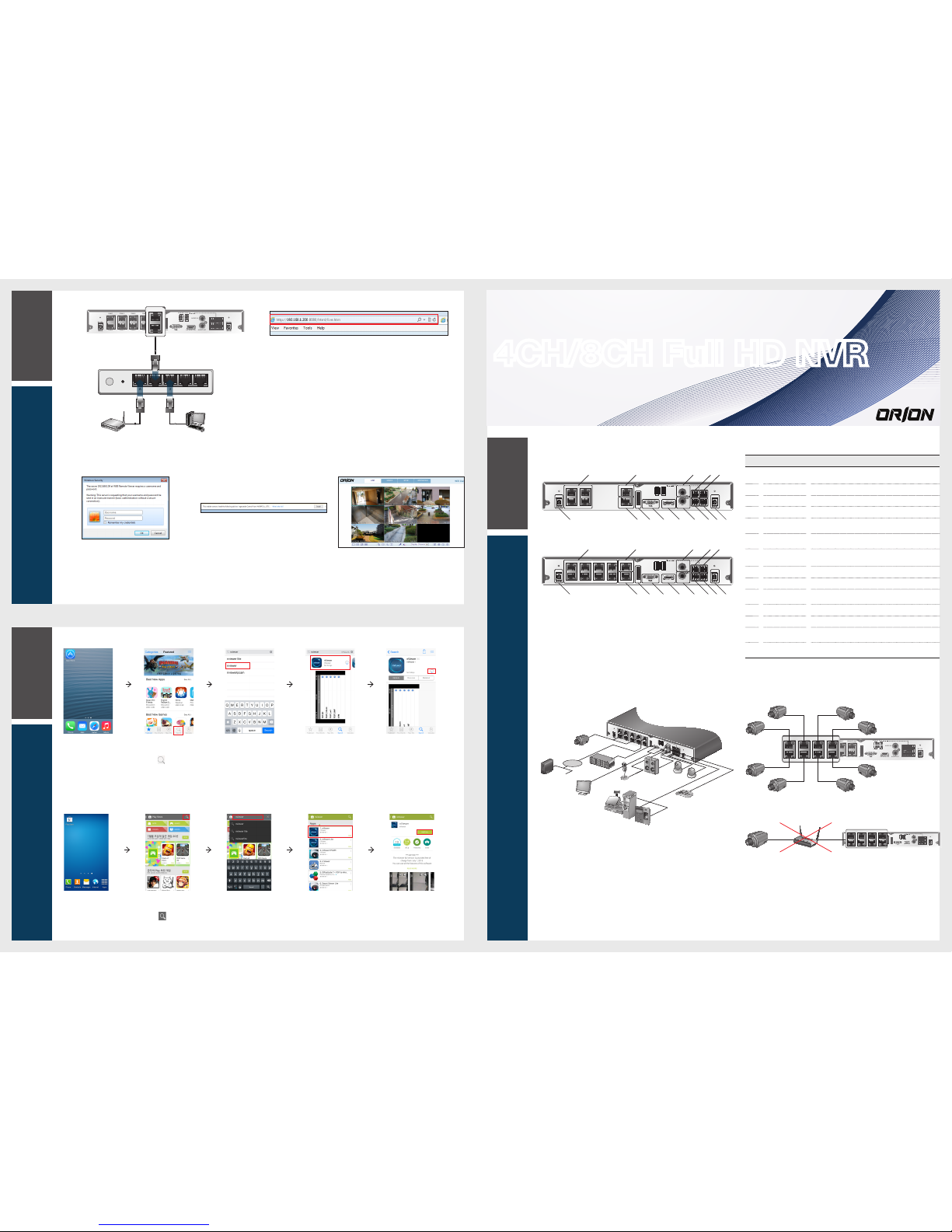
Connecting the camera
If the IP camera provides the alarm I/O port or Audio I/O por t, you can make alarm or audio
connection. For more details, refer to the user manu al of the IP camera.
J
This product works only in a separate dedic ated network to the IP cameras for stable recording
performance.
This is why this product does not operate at all if connecte d to the IP camera via the same
network shared with the hub or router.
4 Channel
8 Channel
No. Item Description
a
CAM1~CAM8
Ethernet ports used for connecting the network ca mera video and power.
It allows supplying power to camera with PoE.
b
WAN(UPLINK) Network port for connecti on to the Internet, router or hub.
c
AUDIO IN Microphone connectio n port.
d
ALARM OUT Alarm Out port.
e
RS-485
Communications por t for connecting peripherals such as system
keyboard.
f
DC 12V
NVR power input port.
Connect to a 12V adaptor.
g
RS-232C
Signal connection por t for POS and ATM.
Scheduled to be upgraded.
h
ALARM IN Alarm input signal port.
i
AUDIO OUT Port for speaker connection.
j
HD MONITOR
Port for connecting a full HD(1920x1080) supported monitor.
Use the HDMI cable to connect with a 1080p 60Hz monitor.
k
VGA VGA video output termi nal.
l
eSATA Connection port for exter nal SATA storage.
m
LAN(DOWNLINK)
Port for connecting the de
dicated network device.
(Do not share with other device.)
n
DC 48V
Power input port for the camera (PoE complia nt).
Connect to a 48V adaptor.
How to download and access the iOS-specific viewer
How to download and access the Android-specific viewer
Network Connection
To access the Web Viewer
2.
When the login dialog appear s, enter the user name
and password.
The default ID and password
- User name : ADMIN
- Password : 1234
Be aware when you enter the ID whether it is upper or lower case
3.
Click the upper warning bar to install the ActiveX
before enabling the add-in functi on.
4.
When the security warnin g window appears, click
<Install>.
5.
When the ActiveX is installed completel y, you will
see the live screen.
For more information about using the Web viewer, refer to
the user manual.
1.
Open the browser and enter the IP address of NVR, or enter the URL address in
the address bar.
ex) if you use the DDNS of the NVR:
http://00115f123456.dvrlink.net :8080
If you do use the IP address of the NVR:
http://192.168.0.210 : 8080
For more information about the router and netwo rk settings, refer to the user
manual of the respective product.
4CH/8CH Full HD NVR
Quick Guide
4WANRESETPWR 3 2 1
WAN(UPLINK)
LAN(DOWNLINK)
HD MONITOR
eSATA
ALARM OUT
ALARM IN
A1 NO
GNDCOM
A2 NC
GNDGND
Tx D +
Rx D -
GNDGND
RS-485
RS-232
AUDIO OUT
DC 12V
AUDIO IN
CAM 1
CAM 2
DC 48V
CAM 3
CAM 4
CAM 5
CAM 6
CAM 7
CAM 8
WAN(UPLINK)
LAN(DOWNLINK)
HD MONITOR
eSATA
ALARM OUT
ALARM IN
A1 NO
GND COM
A2 NC
GND GND
Tx D +
Rx D -
GND GND
RS-485
RS-232
AUDIO OUT
AUDIO IN
ADSL Modem
Local PC
Broadband
Router
WAN(UPLINK)
LAN(DOWNLINK)
HD MONITOR
eSATA
ALARM OUT
ALARM IN
A1 NO
GNDCOM
A2 NC
GND GND
Tx D +
Rx D -
GND GND
RS-485
RS-232
AUDIO OUT
DC 12V
AUDIO IN
CAM 1
CAM 2
DC 48V
CAM 3
CAM 4
a b c d e
g fhn m l k ij
WAN(UPLINK)
LAN(DOWNLINK)
HD MONITOR
eSATA
ALARM OUT
ALARM IN
A1 NO
GNDCOM
A2 NC
GND GND
Tx D +
Rx D -
GND GND
RS-485
RS-232
AUDIO OUT
DC 12V
AUDIO IN
CAM 1
CAM 2
DC 48V
CAM 3
CAM 4
CAM 5
CAM 6
CAM 7
CAM 8
a b c d e
g fhn m l k ij
WAN(UPLINK)
LAN(DOWNLINK)
HD MONITOR
eSATA
ALARM OUT
ALARM IN
A1 NO
GNDCOM
A2 NC
GNDGND
Tx D +
Rx D -
GNDGND
RS-485
RS-232
AUDIO OUT
DC 12V
AUDIO IN
CAM 1
CAM 2
DC 48V
CAM 3
CAM 4
CAM 5
CAM 6
CAM 7
CAM 8
WAN(UPLINK)
LAN(DOWNLINK)
HD MONITOR
eSATA
ALARM OUT
ALARM IN
A1 NO
GNDCOM
A2 NC
GND GND
Tx D +
Rx D -
GND GND
RS-485
RS-232
AUDIO OUT
DC 12V
AUDIO IN
CAM 1
CAM 2
CAM 3
CAM 4
CAM 5
CAM 6
CAM 7
CAM 8
IP Camera Hub or Router NVR
WAN(UPLINK)
LAN(DOWNLINK)
HD MONITOR
eSATA
ALARM OUT
ALARM IN
A1 NO
GNDCOM
A2 NC
GNDGND
Tx D +
Rx D -
GNDGND
RS-485
RS-232
AUDIO OUT
DC 12V
AUDIO IN
CAM 1
CAM 2
DC 48V
CAM 3
CAM 4
CAM 5
CAM 6
CAM 7
CAM 8
LAN(DOWNLINK)
CAM 1
CAM 2
CAM 3
CAM 4
CAM 5
CAM 6
CAM 7
CAM 8
WAN(UPLINK)
LAN(DOWNLINK)
HD MONITOR
eSATA
ALARM OUT
ALARM IN
A1NO
GNDCOM
A2NC
GNDGND
TxD +
Rx D -
GNDGND
RS-485
RS-232
AUDIO OUT
DC 12V
AUDIO IN
CAM 1
CAM 2
DC 48V
CAM 3
CAM 4
CAM 5
CAM 6
CAM 7
CAM 8
VGA
Control
Device
POS
ATM
Access
controller
Sensor
Alarm
Speaker
Microphone
Full HD monitor
eSATA (for external
storage device)
IP Camera
Internet
Network
Attached
Storage
CMS,
Web viewer
Mobile viewer
1.
From your iPhone,
access App store.
2.
From the lower
menu bar, click
<
>.
3.
Type "nViewer" in
the search bar.
4.
Select "nViewer"
to install it.
5.
When done,
select "nViewer"
again to run it.
1.
From your
smart phone,
access the
Market.
2.
From the top
menu bar, click
<
>.
3.
Type "nViewer"
in the search
bar.
4.
Select "nViewer"
to install it.
5.
When done,
select "nViewer"
again and
install it.
Page 2
3
Recording
5
Network
Setting
4
Search
Item Descriptio n
MENU
ADMIN
OSD
OFF
OW
01-01-2014
01:26:19
Select one of the system setup, search and backup menu items befo re
accessing it.
ADMIN
OSD
OFF
OW
01-01-2014
01:26:19
Show the ID of the user who has currently logged in.
OSD
OFF
OW
01-01-2014
01:26:19
Edit the screen layout to show the status bar and timeline at all times or onl y
when the mouse cursor hovers on the status bar/timeli ne.
OSD
OFF
OW
01-01-2014
01:26:19
Select a split mode.
OSD
OFF
OW
01-01-2014
01:26:19
Select Auto Sequence or Specia l Split Mode.
OSD
OFF
OW
01-01-2014
01:26:19
Display or hide the OSD menu on the screen.
OW
01-01-2014
01:26:19
Move to the PTZ screen. You can control the PTZ operations of a PTZcompliant camera on the PTZ scre en.
OW
01-01-2014
01:26:19
Move to the Digital Zoom.
OW
01-01-2014
01:26:19
Display the log list of the recent recording events.
Item Descriptio n
OW
01-01-2014
01:26:19
You can use the camera supporting the audio input to listen to the audio.
OW
01-01-2014
01:26:19
Select a camera to which the audio signal wi ll be transferred from the
connected microphone.
OW
01-01-2014
01:26:19
Start the panic recording.
OW
01-01-2014
01:26:19
Turns on if an event occurs. It does not turn on if no reaction to the event is yet
defined. Click this to check the information of the event that occ urred.
OW
01-01-2014
01:26:19
Check if network connectio n is made via an external PC or mobile device.
Click this to view the details of the concurrent user s and to check the network
connection status.
OW
01-01-2014
01:26:19
Show the disk space information. If you have set the disk overwr ite mode, it will
be displayed "OW" (Over Write) from the start point of the overwri ting.
Click this to view the details of the disk status.
01-01-2014
01:26:19
Display the current time and date.
Language Setting
Date/Time Setting
Status Bar
Besides the remote control buttons, you can also us e the buttons on the bottom status bar to control the NVR.
1.
Press [SETUP] on the remote control, or select <Menu> - <System Se tup> from
the status bar.
2.
From <System Setup> - <Display>, select <OSD>.
3.
Select a preferred language.
4.
Click <Apply>.
1.
Press [SETUP] on the remote control, or select <Menu> - <System Se tup> from
the status bar.
2.
From <System Setup> - <System>, select <Date/Tim e>.
3.
Specify the display format of the curre nt time and date.
J
As the existing data in the same time and date will be deleted if duplic ates are found, back up the
existing data for later use.
4.
Click <Apply>.
Item Description
Channel No Displ ay the number of the current channel.
Play Start playing the video of the selected ch annel from the specified time.
Zoom Zoom the vide o of the selected channel.
Snapshot Capture
Capture the current live video and save it in the .jpeg format.
Then, you can save the captured video in the HDD or export it to
an external USB memory devic e.
Audio ON/OFF Turn on or off the audio si
gnal of the selected channel.
Microphone On/Off Turn on or off the microphone signal of the selected chann el.
ONE PUSH
Automatically adjusts the focus, withi n the camera
’
s focus range.
It is available only if supported by the conne cted camera.
Item Description
Timeline Date
01-01-2014
Display the date of the current timeline.
Click this to select a desired date of the timeline.
Zoom in/out the
timeline
01-01-2014
Expand or collapse the timeli ne.
Navigation
through Timeline
Move to the previous or next point of time in the timeline.
You can also use the mouse wheel to navigate through the
timeline.
Timeline Bar
01-01-2013
Represent the recorded data. The co lor of each bar
indicates:
~
Green : Continuous Recording
~
Red : Alarm Recording
~
Blue : Motion Recording
~
Yellow: Panic Recording
Double-click the timeli ne to move to the Playback mode. Drag and drop it to make backup or
event search for the specified area.
Video Window Quick Menu
Status Bar
Timeline
2
Getting
Started
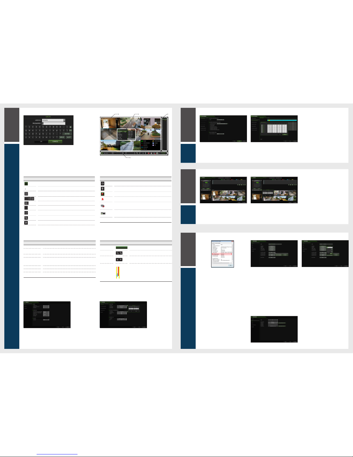
Automatic Recording Setting
1.
Press [MENU] on the remote control, and use the
direction buttons to select <RECORD SE TUP> and
press [ENTER].
Alternatively, you can select <MENU> - <RECORD
SETUP> from the status bar.
2.
Set <RECORD SETUP MODE> to <AUTO
CONFIGURATION>.
3.
Select "Automatic Record Configuration Mod e".
CONTINUOUS RECORD : Records always
regardless of events.
-LONG DURATION BUT LOW QUAILTY :
Recording will proceed in the low quali ty at all
times. As this option will always make recording
in the low quality, the recording period is the
longest compared to the other record mode s.
Time Search
1.
From the <SEARCH> menu, select <TIME
SEARCH>.
2.
Specify the search date and time from the cal endar
in the left corner of the screen.
3.
You can identify the type of the recording data by the
color in the bar.
Yellow Green (Pre recording) : The pre-recording is
performed on the recordin g data after you set the
<PRE RECORDING TIME> from <OPERATION
MODE>.
Green (Continuous) : The continuous rec ording is
performed on the recordin g data.
Red (Alarm) : The alarm event recording is
performed on the recordin g data.
Blue (Motion) : The motion event recording is
performed on the recordin g data.
Yellow (Panic) : The panic manual recording is
performed on the recordin g data.
4.
Click to move to a desired start time in the time bar,
or use the buttons at the bottom of the status bar to
make search.
5.
Select an item to play and click <PLAY>.
J
Click to move to a desired time, or simply double-click a
desired time in the time bar to play the video data on that
time.
For details on thumbnail search and event se arch, refer to
the user manual.
Network Connection Setting
To configure the network settings
1.
Connect the [WAN(UPLINK )] port in the rear panel
of the NVR to any port available except for the WAN
port of the router.
2.
Connect the [WAN(UPLINK )] port of the router directly to
the fixed IP LAN cable, or connect it to the xDSL modem.
3.
Check the network address infor mation if using a
network environment conn ected to the same router.
Enter the network setting menu of the NVR and
provide the IP addres
s.
1)
From the main menu of the NVR, move to <SYSTEM
SETUP> - <NETWORK> - <IP SETUP>.
2)
Uncheck the DHCP checkbox and provide the
necessary inform ation manually.
(Check the network address informa tion in the
network environment set tings and enter the correct
information.)
IP ADDRESS : 192.168.0.123 (enter the network IP
address.)
GATEWAY : 192.168.0.1 (enter the gateway address.)
SUBNET MASK : 255.255.255.0 (type the subnet
mask.)
The primary, the secondary DNS se rver :
168.126.63.1 (enter the address of a DNS server.)
-HIGH QUAILITY BUT SHORT DURATION :
Recording will proceed in the best qua lity at all
times. As this option will always make recording
in the best quality, the recording period is the
shortest compared to the other record mod es.
MOTION RECORD : Recording will proceed onl y
if a motion is detected.
ALARM RECORD : Recording will proc eed only if
an alarm event occurs.
MOTION/ALARM RECORD : Recording will
proceed only if a motion is detected or an alarm
event occurs.
INTENSIVE MOTION RECORD : Normally record ing
will be performed in a low qualit y. However, the
quality will switch to high if a motion is detected.
INTENSIVE ALARM RECORD : Norma lly recording
will be
performed in a low quality. However, the
quality will switch to high if an alarm event occur s.
INTENSIVE MOTION/ALARM RECORD : Normal ly
recording will be perform ed in a low quality.
However, the quality will switch to high if an alarm
event occurs or a motion is detected.
4.
Click <APPLY>.
AUTO PORT UPDATE : Regularly updates the
selected WEB and RTSP ports of the router through
UPNP function.
AUTO PORT STATUS : Regularly updates the
selected WEB and RTSP ports of the router through
UPNP function.
Enter an IP address that falls in the private IP range
provided by the router.
ex) 192.168.1.2~254, 192.168.0.2~254, 192.168.
3)
When done, configure the port for warding for RTSP
and Web Service ports by clicki ng Port Forwarding.
(The default value of the Web servic e port is 8080.)
4)
Click <PORT FORWARDING> for each. You will see
the confirmation message. Clic k <APPLY> and exit
the menu.
5)
The network settings of the NVR are compl ete.
Some router models may not support UPNP prope rly.
If you see a failure message after <PORT FORWARDIN G>
settings, refer to the user manual of the router and configur e
the DMZ or port forwarding setti ngs manually.
5.
When the network configuratio n is complete,
proce
ed with the DDNS settings to allow access to
the NVR from outside.
From the main menu of the NVR, move to <SYSTEM
SETUP> - <NETWORK> - <DDNS>.
6.
Rename the NVR. (The default nam e of the NVR is the
MAC address of the NVR.)
Enter a desired name in combination of charac ters and
numbers.
7.
When done, click <DDNS REGISTRATION TEST>
and <DDNS CONNECTION TEST> in this order.
If you receive a success message.
Check the NVR
address and click <APPLY> at the bottom.
8.
Check the NVR address and the Web servic e port in
the network settings to make sure that any Internetconnected PC can access the NVR.
9.
If you type "mydvr" for the NVR name from the DDN
item, the address of the Web viewer is "http://mydvr.
dvrlink.net: 8080".
Language Setting
Date/Time Setting
Status Bar
Besides the remote control buttons, you can also us e the buttons on the bottom status bar to control the NVR.
1.
Press [SETUP] on the remote control, or select <Menu> - <System Se tup> from
the status bar.
2.
From <System Setup> - <Display>, select <OSD>.
3.
Select a preferred language.
4.
Click <Apply>.
1.
Press [SETUP] on the remote control, or select <Menu> - <System Se tup> from
the status bar.
2.
From <System Setup> - <System>, select <Date/Tim e>.
3.
Specify the display format of the curre nt time and date.
J
As the existing data in the same time and date will be deleted if duplic ates are found, back up the
existing data for later use.
4.
Click <Apply>.
Timeline
Quick Menu
Log In
Live Screen
1.
When the system starts, the login screen ap pears.
2.
Select the user ID and enter the password.
The default user ID is
“
ADMIN”; the default password is “1234”.
3.
Click <OK>.
J
For the security purpose, chan ge the password right after you purchased the product.
 Loading...