

Oregon Scientific WMR86NSA, WMR86NS User Manual

1
Pro Colour Weather Station
Model: WMR86NS / WMR86NSA
USER MANUAL

1
EN
INTRODUCTION
Thank you for selecting the Oregon Scientic™ Weather
Station (WMR86NS / WMR86NSA).
The base station is compatible with other sensors. To purchase
additional sensors, please contact your local retailer.
Sensors with this logo
are compatible with this
unit.
NOTE Please keep this manual handy as you use
your new product. It contains practical step-by-step
instructions, as well as technical specifications and
warnings you should know about.
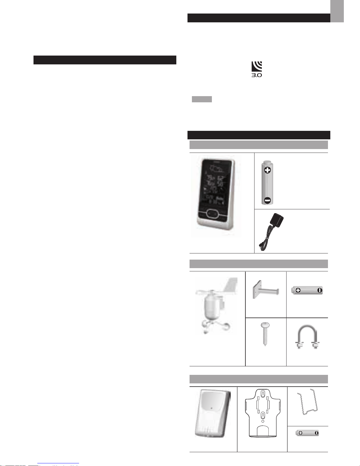
PACKAGING CONTENTS
BASE STATION
WIND SENSOR
TEMPERATURE & HUMIDITY SENSOR
1 x Base Station
3 x AA UM-3
1.5V batteries
1x Power
Adapter
Pro Colour Weather Station
Model: WMR86NS / WMR86NSA
USER MANUAL
1 x Wind Sensor (1
x Wind Vane Above
and 1 x Anemometer
Below)
1 x sensor
connector
2 x AA UM-3
1.5V batteries
4 x Screws
(Type A)
1 x Round
U- bolt
2 x AAA UM-4
1.5V battery
1 x wall mount
bracket
1 x Temperature /
Humidity Sensor
1 x Table stand
CONTENTS
Introduction ...............................................................1
Packaging Contents
.................................................1
Base Station
........................................................1
Wind Sensor
........................................................ 1
Temperature & Humidity Sensor
.......................... 1
Rain Gauge
..........................................................2
Accessories - Sensors
.............................................2
Overview
....................................................................2
Front View
............................................................2
Back View
............................................................ 2
LCD Display
......................................................... 2
Wind Sensor
........................................................ 3
Rain Gauge
..........................................................4
Outdoor Temperature / Humidity Sensor
............. 4
Getting Started
..........................................................4
Set Up Remote Wind Sensor
...............................4
Set Up Remote Temperature / Humidity Sensor
. . 4
Set Up Rain Gauge
..............................................4
Set Up Base Station
............................................5
Connect AC Adapter
............................................ 5
Verify Connection
.....................................................5
Wind Sensor
........................................................ 5
Temperature / Humidity Sensor
........................... 5
Rain Gauge
..........................................................5
Mounting / Placing Of Sensors
...............................6
Wind Sensor
........................................................ 6
Temperature / Humidity Sensor
........................... 6
Rain Gauge
..........................................................6
Clock Reception
.......................................................6
Clock / Calendar
.......................................................7
Moon Phase
..............................................................7
Auto Scanning Function
..........................................7
Weather Forecast
.....................................................7
T emperature And Humidity
......................................8
Temperature And Humidity Trend
........................ 8
Wind Chill / Direction / Speed
..................................8
Uvi / Barometer / Rainfall
.........................................8
UV Index
.............................................................. 9
Barometer
............................................................ 9
Rainfall
................................................................. 9
Backlight
...................................................................9
Reset
..........................................................................9
Specications
...........................................................9
Precautions
.............................................................10
About Oregon Scientic
........................................ 11
EU Declaration Of Conformity
............................... 11
FCC statement
........................................................ 11
DISPOSAL INFORMATION FOR USERS
............... 11
2
EN
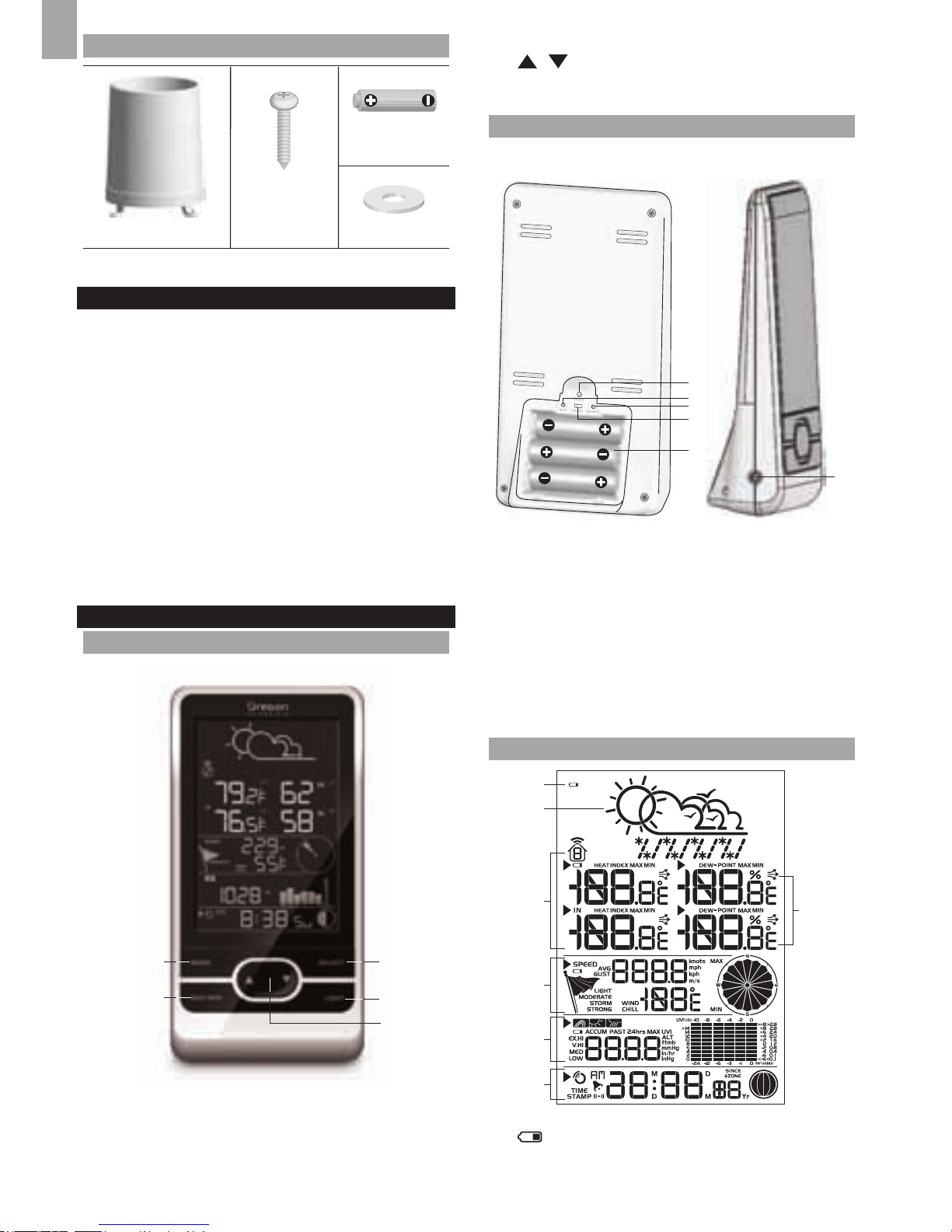
RAIN GAUGE
ACCESSORIES - SENSORS
This product can work with up to 3 sensors at any one
time to capture outdoor temperature, relative humidity or
UV readings in various locations.
Optional wireless remote sensors such as those
listed below can be purchased separately. For more
information, please contact your local retailer.*
• Solar Panel STC800 connectable to Wind Sensor and
Temperature / humidity sensor
• Thermo-hygro THGR800 (3-Ch)
• Thermo-hygro THGR810 (10-Ch)
• UV UVN800
• Pool sensor THWR800
* Features and accessories will not be available in
all countries.
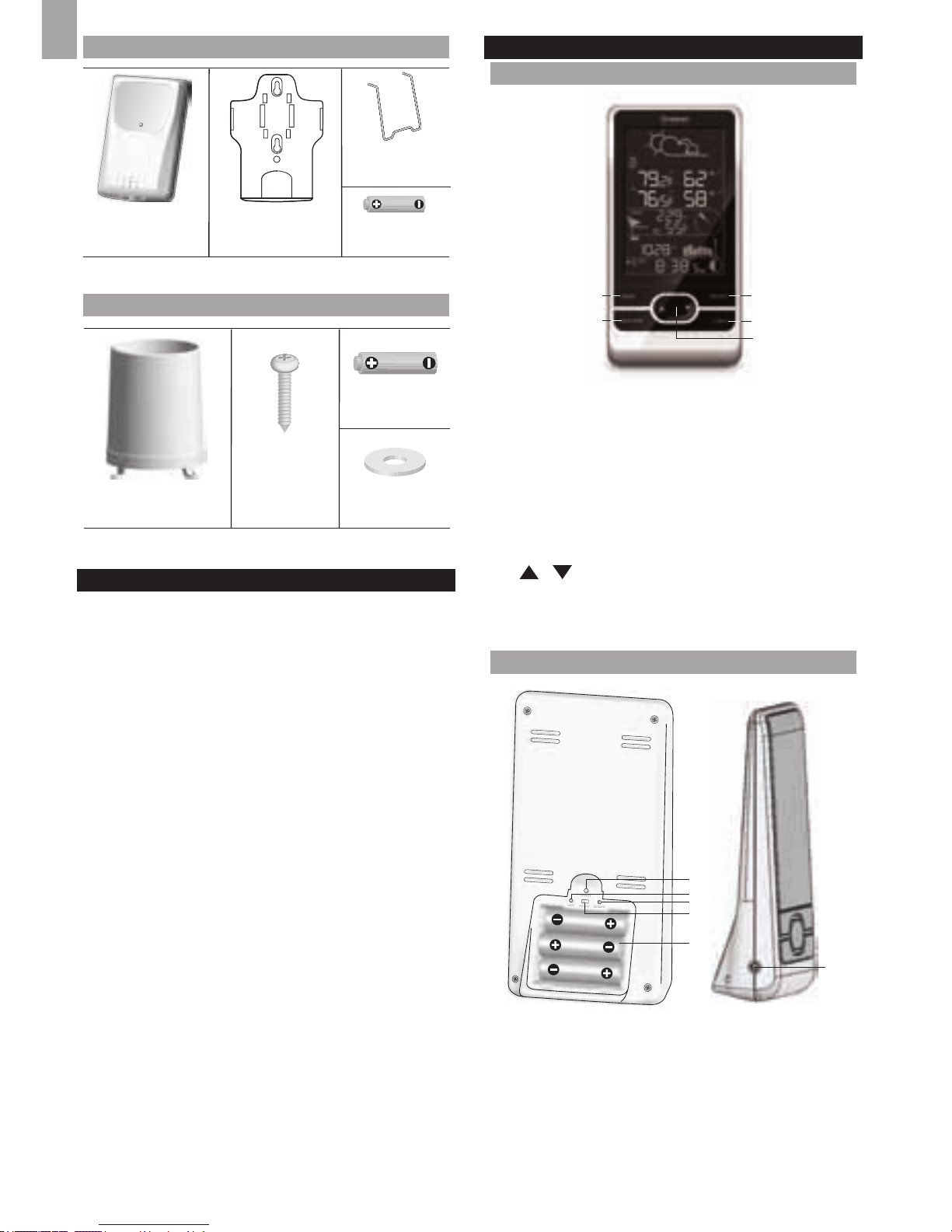
OVERVIEW
FRONT VIEW
31
2
4
5
1. MODE: Switch between the different display modes
/ settings; set clock; set altitude; activate autoscan
2. MAX/MIN: Read the max / min memory readings;
clear readings
3. SELECT: Switch between the different areas
2 x AA UM-3
1.5V batteries
4 x Screws
(Type B)
1 x Rain Collector
4. LIGHT: Activate backlight
5. / : Increase / decrease values of the selected
setting; toggle between outdoor channels
BACK VIEW
1
2
4
3
5
6
1. RESET: Returns unit to default settings
2. UNIT: Select unit of measurement
3. SEARCH: Searches for sensors or for the radio-
controlled clock signal
4. EU / UK switch: Select the nearest radio signal
(WMR86NS only)
5. Battery compartment
6. AC power adapter jack
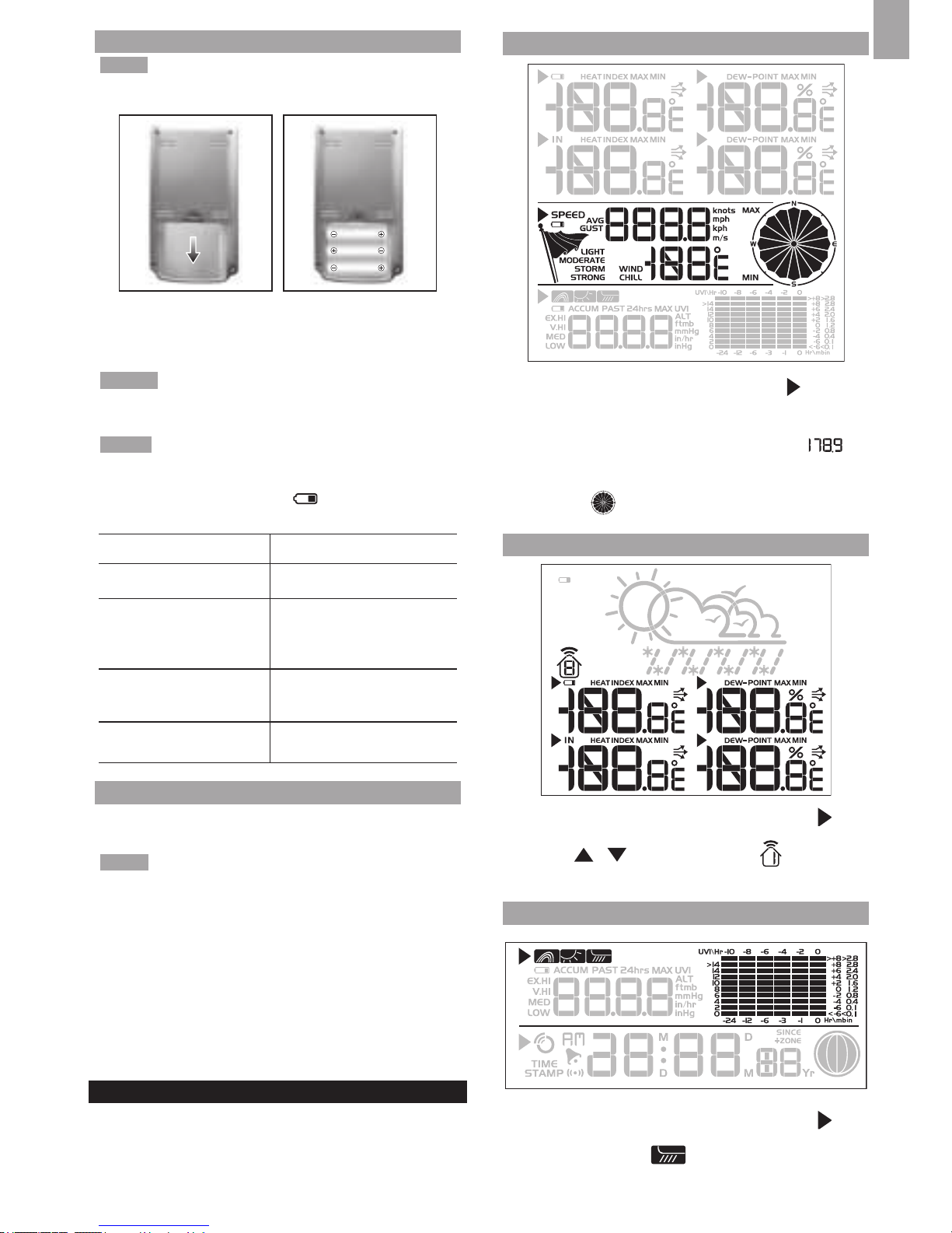
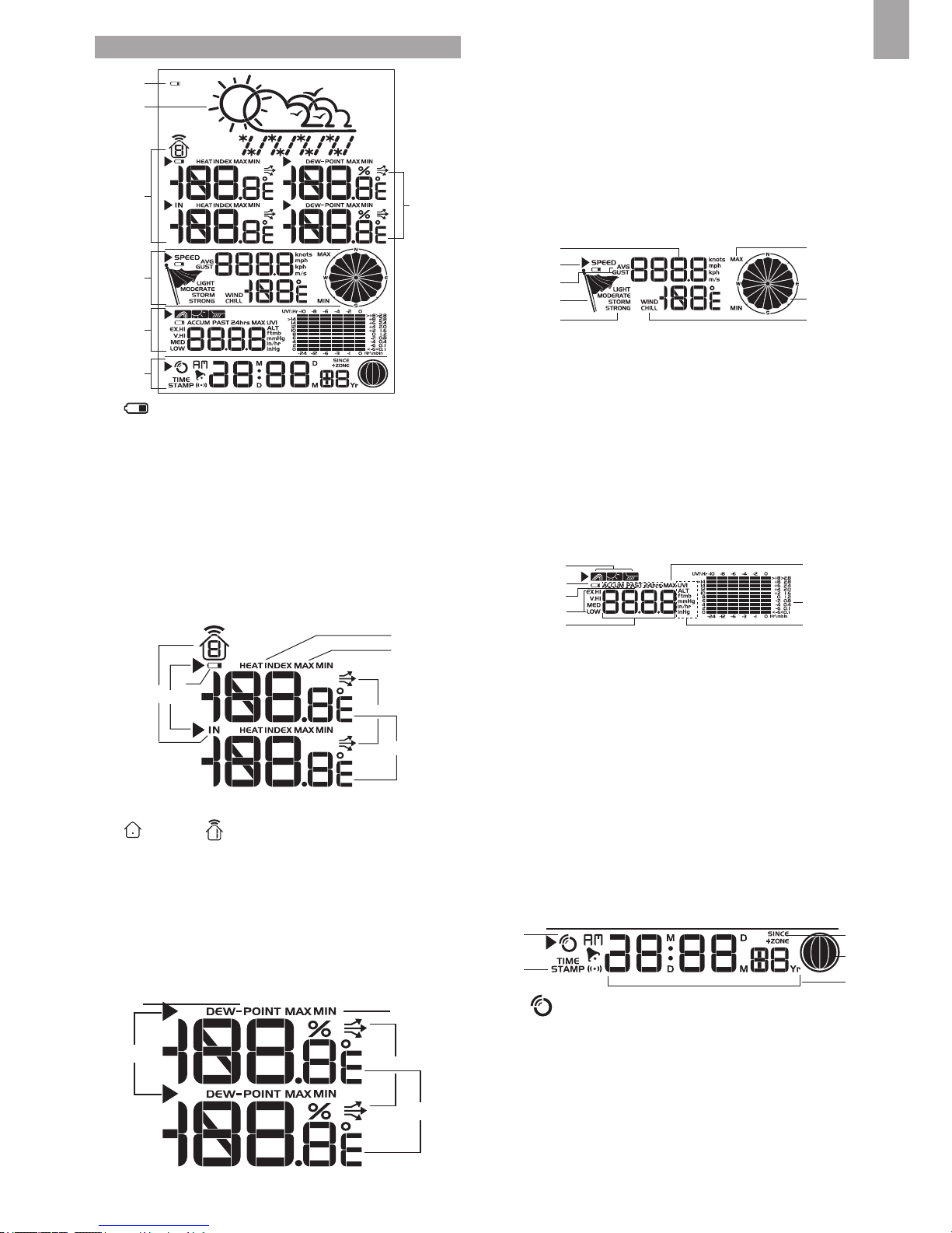
LCD DISPLAY
1
2
A
B
C
D
E
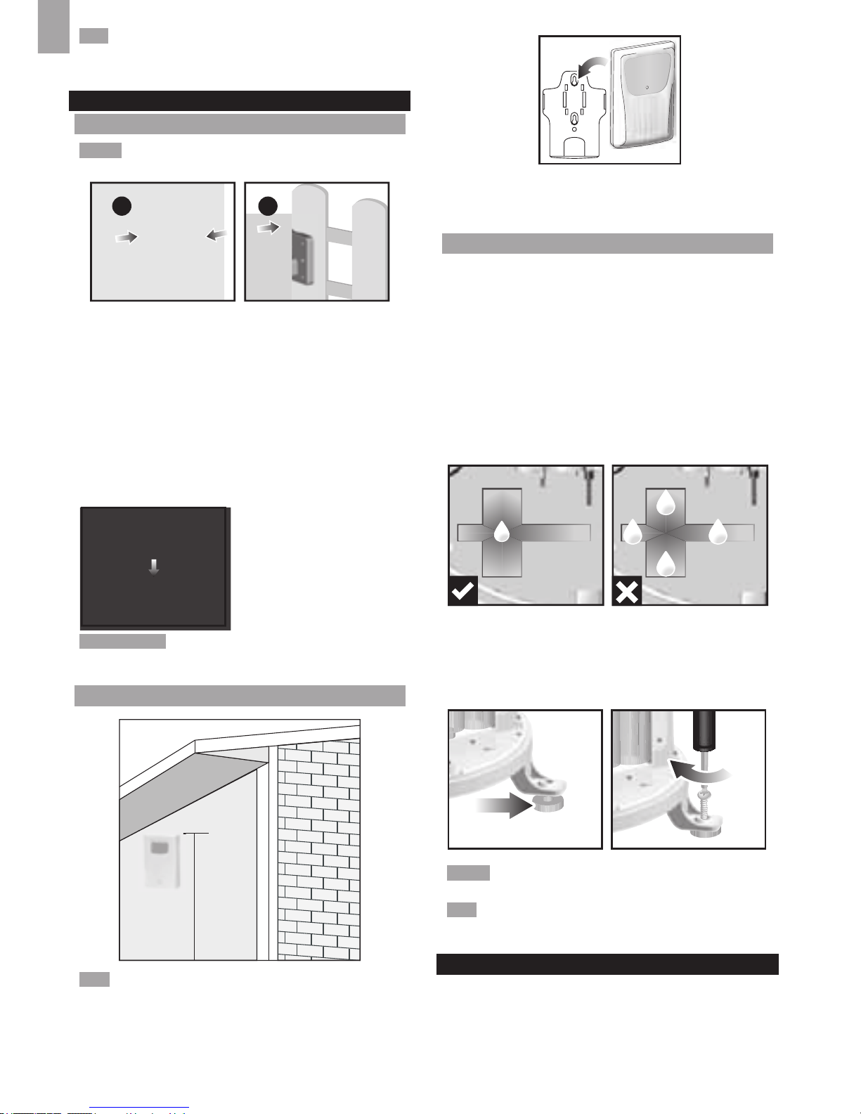
1. : Main unit battery low
2. Weather forecast
6 x Washers
3
EN
A. Temperature/Heat Index Area
B. Humidity / Dew Point Area
C. Wind Speed / Wind Direction / Wind Chill Area
D. UVI / Barometer / Rainfall Area
E. Clock / Calendar / Moon Phase Area
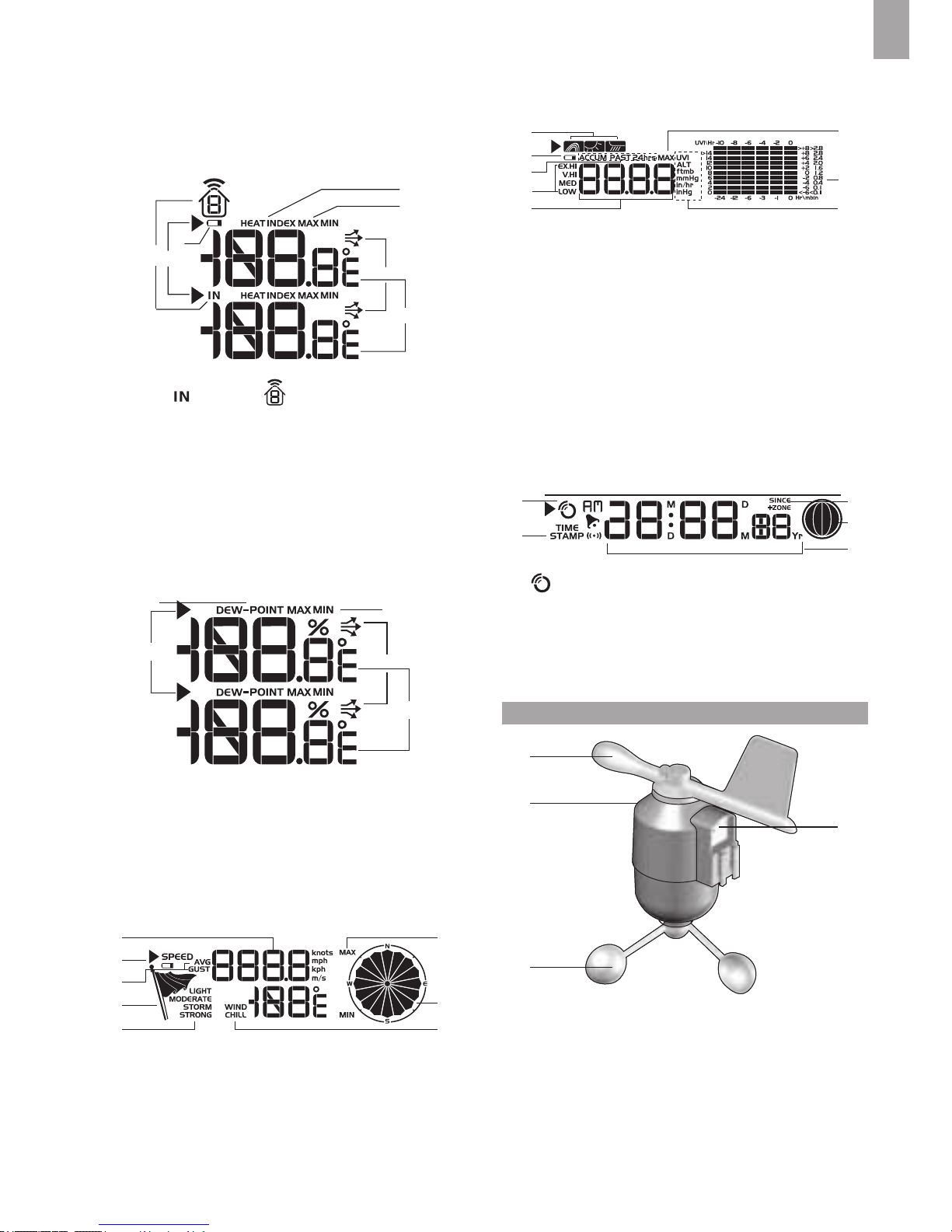
A Temperature Area
1
3
2
5
6
7
4
1. Indoor / Outdoor channel temperature and
humidity is displayed
2. Outdoor sensor battery is low
3. Selected area icon
4. MAX / MIN temperature is displayed
5. Temperature trend
6. Temperature reading (°C / °F)
7. Heat Index
B Humidity / Dew Point Area
1
2
5
3
4
1. Dew point level – Temperature is displayed
2. MAX / MIN humidity / dew point level is displayed
3. Humidity trend
4. Humidity reading
5. Selected area icon
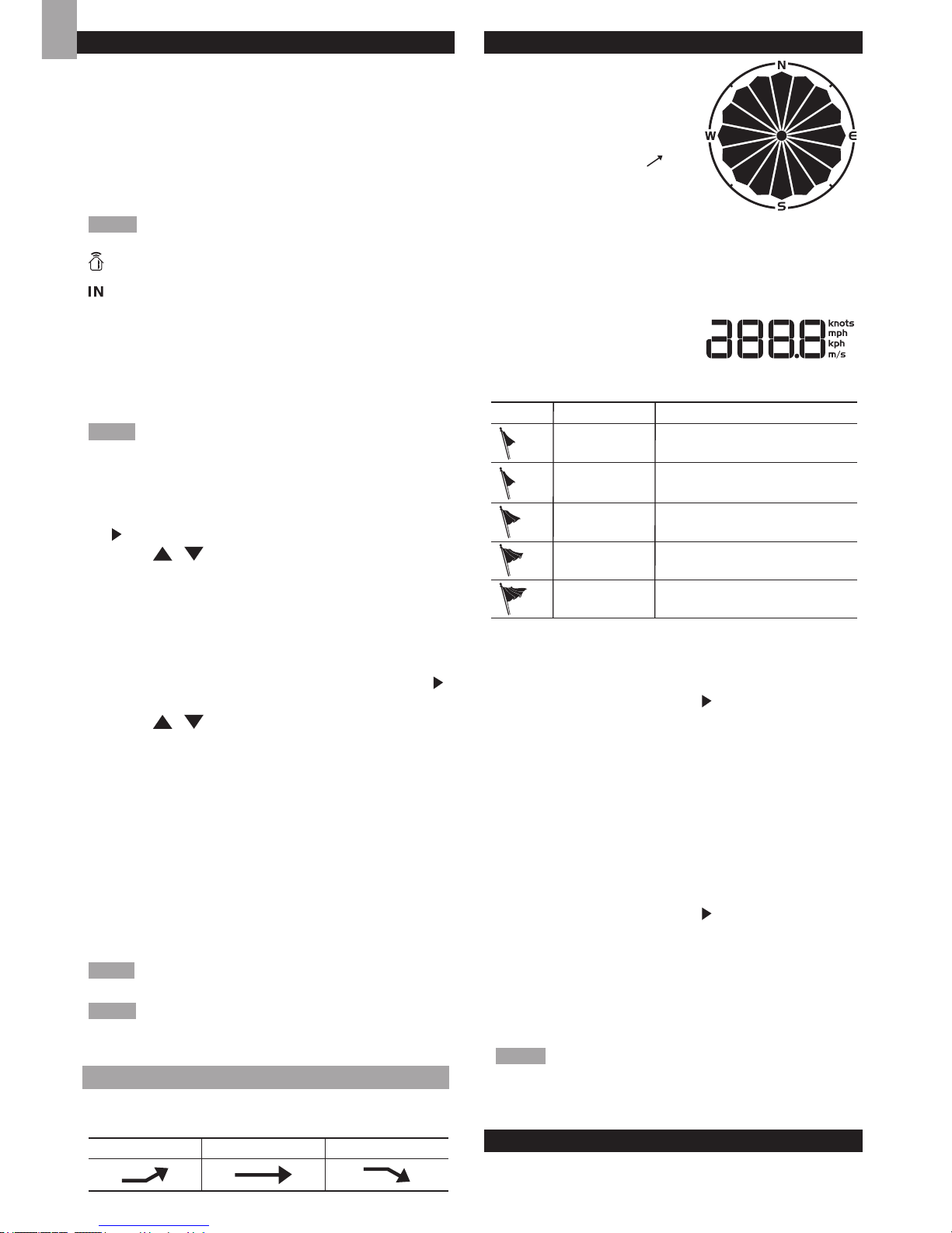
C Wind Speed / Wind Direction / Wind Chill Area
3
1
2
5
6
4
8
7
1. MAX wind speed memory display
2. Wind speed reading (m/s, knots, kph or mph)
3. Outdoor wind sensor low battery display
4. Wind speed indicator (AVG/GUST)
5. Wind speed level indicator
6. Wind speed level description
7. Minimum wind chill display
8. Wind direction indicator
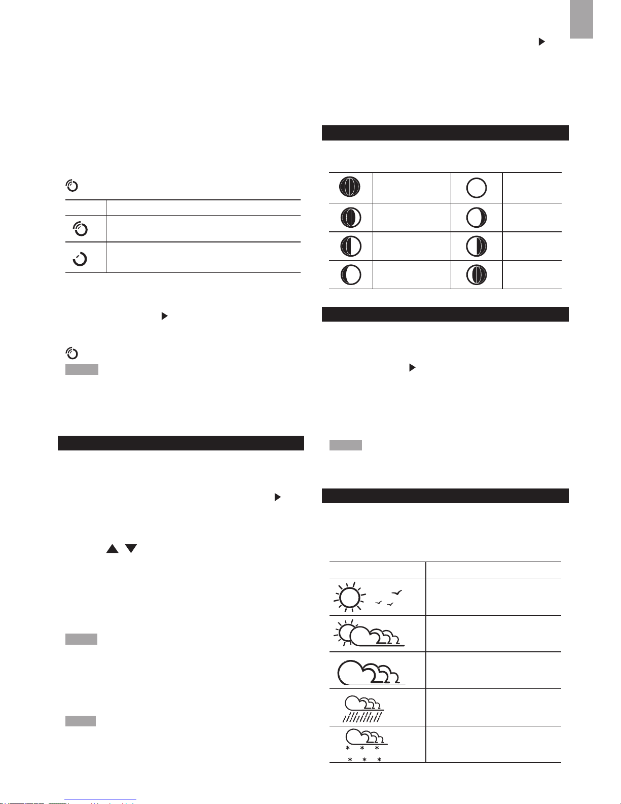
D UVI / Barometer / Rainfall Area
1
2
3
5
4
7
8
6
1. Barometer/UVI/rainfall reading indicator
2. Outdoor UVI/rain sensor low battery display
3. ACCUM/PAST 24hrs – displays accumulative/past
24 hours rainfall
4. Barometer/UVI/rainfall readings
5. UVI level indicator
6. Barometric pressure/UVI/rainfall units displayd
7. MAX barometer/UVI/rainfall display
8. Barometric pressure/UVI/rainfall historical bar chart
display
E Clock / Calendar / Moon Phase Area
1
2
3
4
5
1. Clock signal reception indicator
2. Timestamp is displayed
3. Time zone offset
4. Moon phase
5. Time / date / calendar
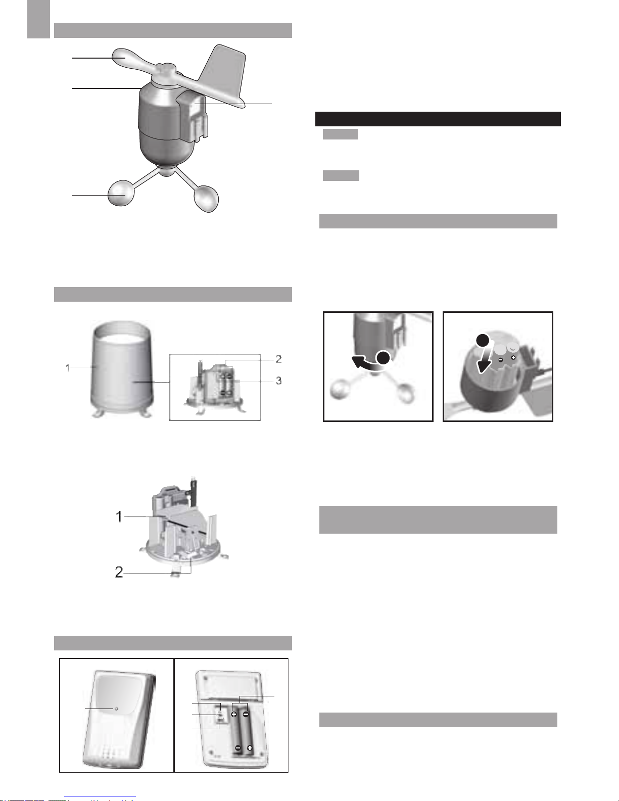
WIND SENSOR
1
2
3
4
1. Wind direction
2. Wind vane casing
3. Anemometer
4. Solar power socket
4
EN
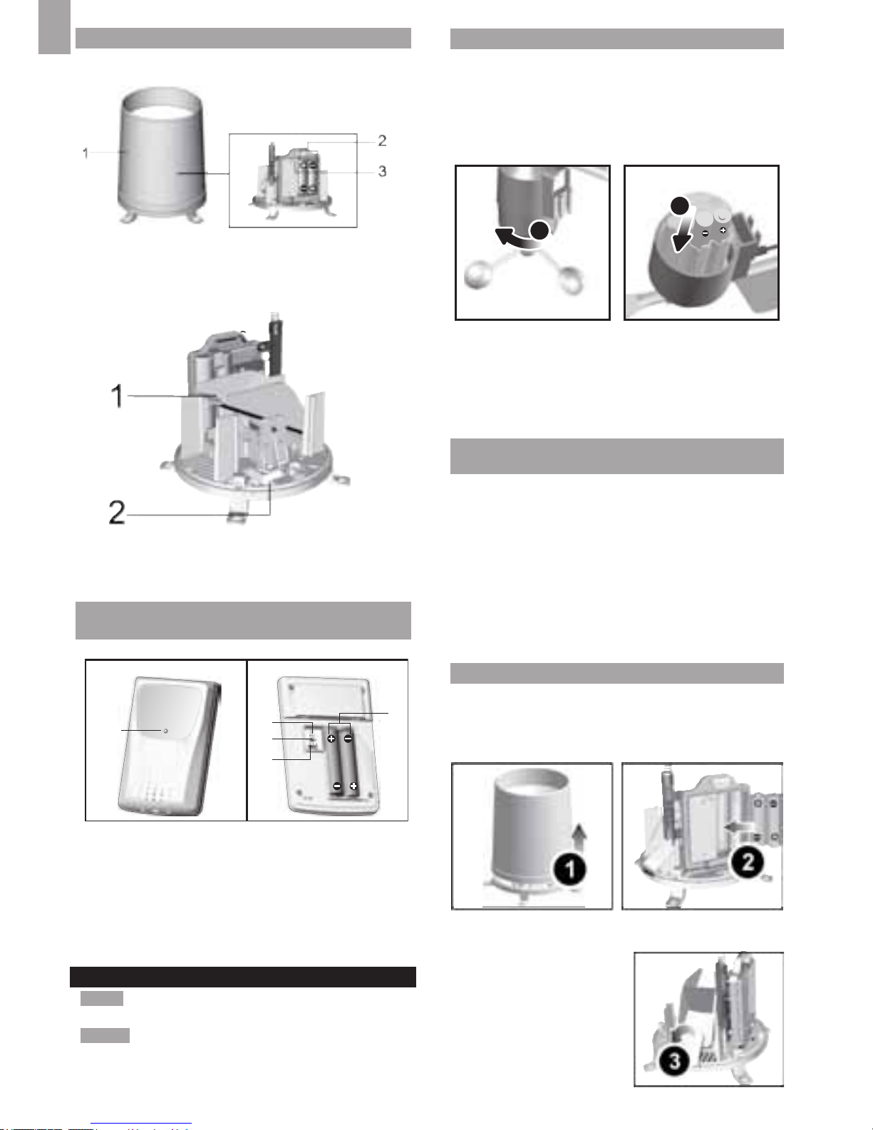
RAIN GAUGE
Base and funnel:
1. Rain gauge
2. Battery compartment
3. RESET button
C
1. Funnel
2. Indicator
OUTDOOR TEMPERATURE / HUMIDITY
SENSOR
1. LED status indicator
2. RESET hole
3. °C / °F: Select temperature unit
4. CHANNEL switch
5. Battery compartment
GETTING STARTED
NOTE Install batteries in the remote sensors before the
base station matching the polarities (+ and -).
NOTE Use alkaline batteries for longer usage and
consumer grade lithium batteries in temperatures below
freezing.
SET UP REMOTE WIND SENSOR
The wind sensor takes wind speed and direction
readings.
The sensor is battery operated. It is capable of
transmitting data to the base station wirelessly within an
approximate operating range of 100 meters (328 feet).
To insert batteries:
1
2
1. Unscrew the anemometer from the wind sensor
carefully.
2. Insert batteries matching the polarities (+ / -) and
replace the anemometer. Press RESET after each
battery change.
SET UP REMOTE TEMPERATURE / HUMIDITY
SENSOR
The remote sensor can collect data from up to 3 channels.
To set up the remote sensor:
1. Slide open the battery door.
2. Slide channel switch to select a channel (1, 2,
3). Ensure you use a different channel for each
sensor.
3. Insert the batteries, matching the polarities (+ / -).
4. Press RESET after each battery change.
5. Close the battery door.
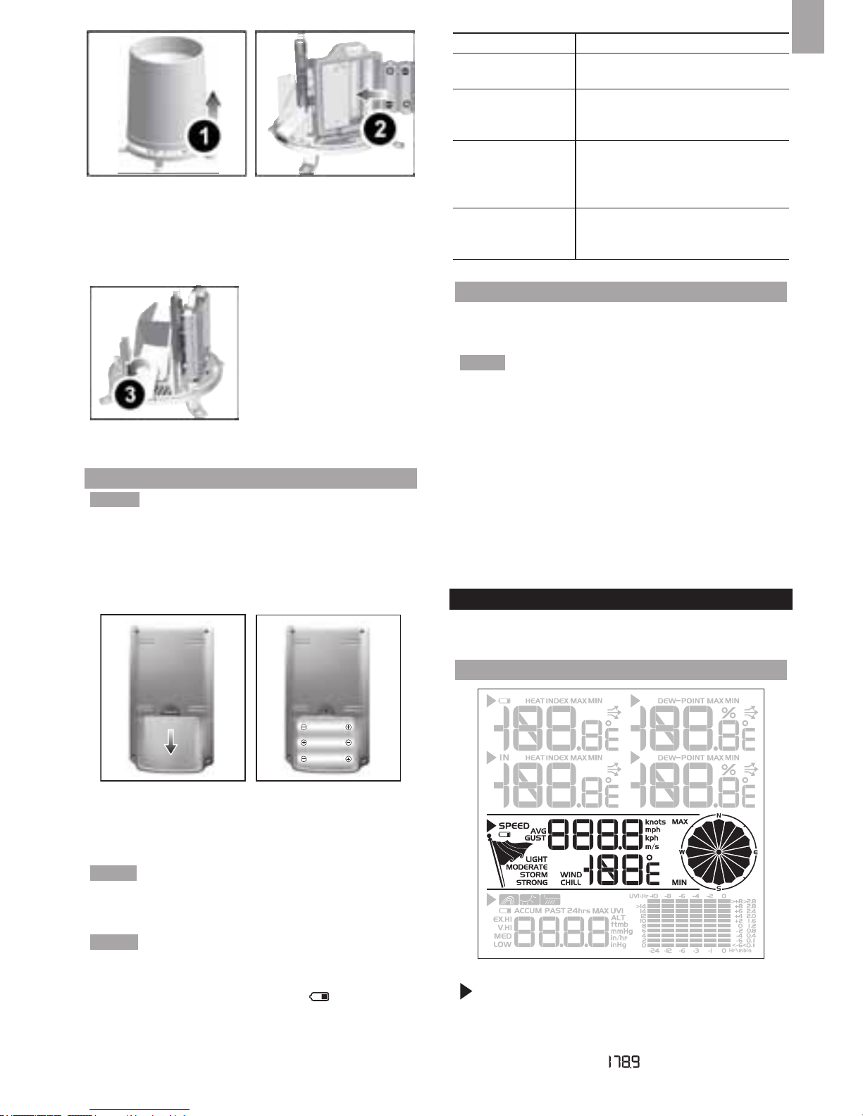
SET UP RAIN GAUGE
The rain gauge collects rain and takes rainfall readings.
The sensor can remotely transmit data to the base
station.
To set up the rain gauge:
1. Remove screws and slide the cover off in an upwards
motion.
2. Insert the batteries (2 x
UM-3 / AA), matching
the polarities (+ / -).
Press RESET after each
battery change.
3. Remove the bre tape.
1
5
2
3
4
CF
5
EN
SET UP BASE STATION
NOTE Install batteries in the remote sensors before the
base station matching the polarities (+ and -).
1. Slide open the battery door.
2. Insert the batteries, matching the polarities (+ / -).
3. Press RESET after each battery change.
4. Close the battery door.
NOTE Do not use rechargeable batteries. It is
recommended that you use alkaline batteries with this
product for longer performance.
NOTE Batteries should not be exposed to excessive
heat such as sunshine or re.
The battery icon indicator
may appear in the
following areas:
AREA MEANING
Weather Forecast Area
Battery in the base station
is low.
Temperature or
Humidity Area
The displayed channel
indicates the outdoor
sensor for which battery
is low.
Wind Speed / Wind
Direction / Wind Chil
Area
Battery in the wind
sensor is low.
UVI / Barometer /
Rainfall Area
Battery in the UV / Rain
sensor is low.
CONNECT AC ADAPTER
Connect the supplied power adapter to the power jack,
then plug into a standard AC outlet.
NOTE
• The batteries are only for back-up use. Always connect
the unit to the power grid source via AC/DC adapter.
• Make sure the adapter is not obstructed and is easily
accessible to the unit.
• The base station and adapter should not be exposed
to wet conditions. No objects lled with liquid, such as
vases, should be placed on the base station and adapter.
• To completely disconnect from power, unplug adapter
from the mains.
VERIFY CONNECTION
Before proceeding to install sensors outside, please verify
communication to the base station.
WIND SENSOR
Press SELECT until the selected area icon is in the
middle display area.
• Wind speed: Gently rotate the wind vane and conrm
a numerical reading on the base station, e.g., .
• Wind direction indicator. Move the direction of the
wind indication and verify the icon moves in the same
direction
.
TEMPERATURE / HUMIDITY SENSOR
1. Press SELECT until the selected area icon is in
the upper display area.
2. Press / to select channel 1 and verify a
numerical reading.
RAIN GAUGE
1. Press SELECT until the selected area icon is in
the lower display area.
2. Press MODE until is displayed.
3. Tilt the tipping funnel on the rain gauge several times
and verify a numerical reading on the base station.
6
EN
TIP If no reading is displayed for a sensor, press and
hold SEARCH button on the base station to initiate a
wireless sensor search.
MOUNTING / PLACING OF SENSORS
WIND SENSOR
NOTE The sensor should be positioned in an open area
away from trees or other obstructions.
a
b
Secure the sensor connector in the desired location:
a. Align the back of the sensor connector to an existing
pole. Secure in place by inserting the ends of the
U-bolt into the holes on the sensor connector and
securing it with washers and bolts.
OR
b. Insert 4 type A screws into the holes of the sensor
connector. Screw rmly into place, i.e., fence.
Slide wind vane onto the smaller end of the sensor
connector.
IMPORTANT Ensure that the wind sensor is pointing
North to enable it to record accurate readings.
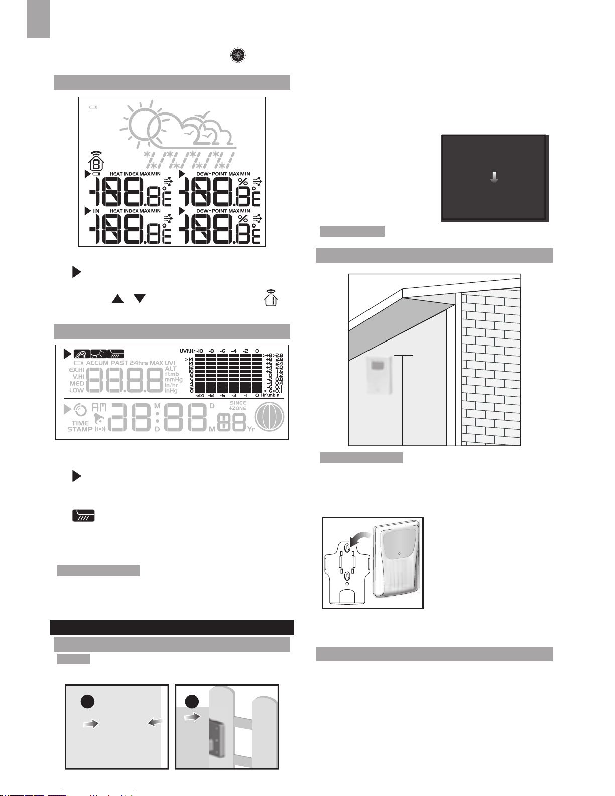
TEMPERATURE / HUMIDITY SENSOR
150cm(5ft)
TIP Ideal placements for the sensor would be in any
location on the exterior of the home at a height of not
more than 1.5 m (5 ft) and which can shield it from direct
sunlight or wet conditions for an accurate reading.
Secure the sensor in the desired location using the wall
mount bracket or table stand.
RAIN GAUGE
The base station and rain gauge should be positioned
within an effective range: about 100 meters (328 feet)
in an open area.
The rain gauge should be mounted horizontally about 1
meter (3 feet) from the ground in an open area away from
trees or other obstructions to allow rain to fall naturally
for an accurate reading.
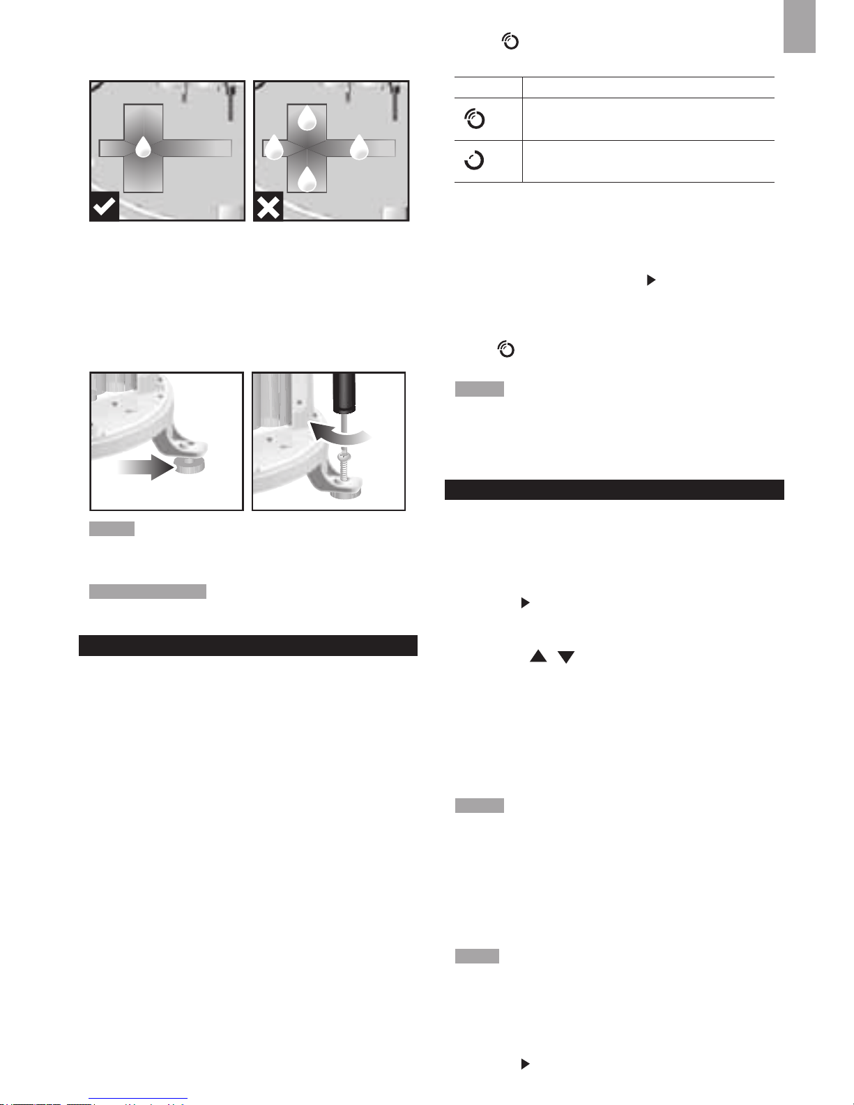
To ensure a level plane:
Put a few drops of water on the cross at the base of the
funnel to check the horizontal level.
1
23
4
Water will pool to the center of the cross when the rain
gauge is level.
If water remains on 1-4, the gauge is not horizontal.
If necessary, adjust the level using the screw.
NOTE For best results, ensure the base is horizontal to
allow maximum drainage of any collected rain.
TIP Press RESET button on base station to erase all
testing data.
CLOCK RECEPTION
This product is designed to synchronize its calendar
clock automatically once it is brought within range of a
radio signal:
WMR86NS:
• EU: DCF-77 signal: within 1500 km (932 miles) of
Frankfurt, Germany.
7
EN
• UK: MSF-60 signal: within 1500 km (932 miles) of
Anthorn, England.
WMR86NSA:
• WWVB-60 signal: within 3200km (2000 miles) of Fort
Collins Colorado.
WMR86NS only - slide the EU / UK switch to the
appropriate setting based on your location. Press RESET
whenever you change the selected setting.
The reception icon will blink when it is searching for a
signal. If the radio signal is weak it can take up to 24
hours to get a valid signal reception.
indicates the status of the clock reception signal.
ICON MEANING
Time is synchronized. Receiving signal is
strong
Time is not synchronized. Receiving signal
is weak
To enable (and force a signal search) / disable the
clock radio reception (clock synchronization):
1. Press SELECT to navigate to the Clock / Calendar /
Moon Phase Area.
will show next to the Area.
2. Press and hold SEARCH.
appears when it is enabled.
NOTE For best reception, the base station should be
placed on a at, non-metallic surface near a window in an
upper oor of your home. The antenna should be placed
away from electrical appliances and not be moved around
when searching for a signal.
CLOCK / CALENDAR
To manually set the clock:
(You only need to set the clock and calendar if you have
disabled the clock radio reception).
1. Press SELECT to navigate to the Clock Area. will
show next to the Area.
2. Press and hold MODE to change the clock setting.
The setting will blink.
3. Press / to increase / decrease the setting value.
4. Press MODE to conrm.
5. Repeat steps 3 to 4 to set the time zone offset hour
(+ / -23 hours), 12 / 24 hour format, hour, minute,
year, date / month format, month, date and weekday
language.
NOTE If you enter +1 in the time zone setting, this will
give you your regional time plus 1 hour.
If you are in the US (WMR86NSA only) set the clock to:
Pacic time Mountain time
Central time Eastern time.
NOTE The weekday is available in English (E), German
(D), French (F), Italian (I), Spanish (S) or Russian (R).
To change the clock display:
1. Press SELECT to navigate to the Clock Area. will
show next to the Area.
2. Press MODE to toggle between:
• Clock with Seconds
• Clock with Weekday
• Calendar
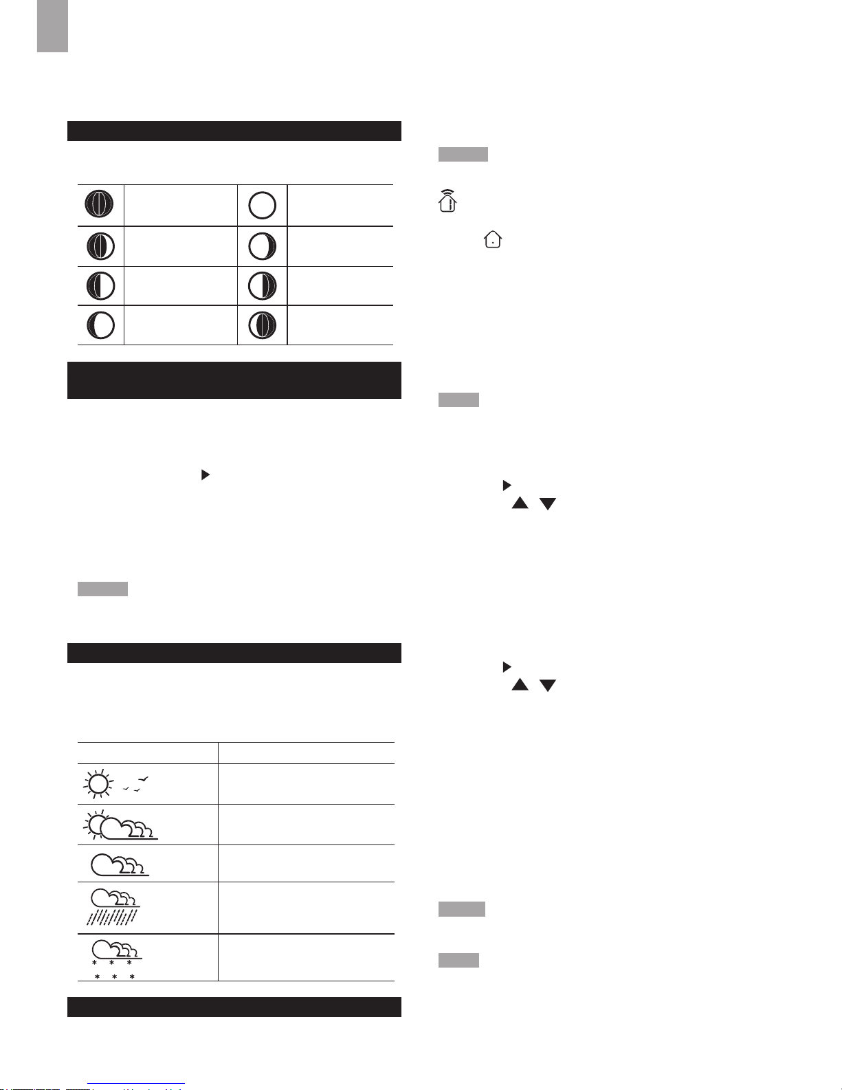
MOON PHASE
The Calendar must be set for this feature to work (see
Clock / Calendar section).
New Moon Full Moon
Waxing
Crescent
Waning
Gibbous
First quarter
Third
quarter
Waxing Gibbous
Waning
Crescent
AUTO SCANNING FUNCTION
To activate the outdoor temperature and humidity
auto-scan function:
1. Press SELECT to navigate to the Temperature or
Humidity Area.
will show next to the Area.
2. Press and hold MODE to activate auto-scan. The
temperature and humidity display will scroll from
indoor to ch1 through to ch3.
3. Press any key except the LIGHT to stop the auto-scan.
NOTE Channel 1 is used for the outdoor temperature
and humidity sensor. Additional temperature and humidity
sensors can use other channels.
WEATHER FORECAST
The weather display in the top part of the screen shows
the current weather and the weather forecast for the next
12-24 hours within a 30-50 km (19-31 mile) radius.
Weather Forecast Area
ICON DESCRIPTION
Sunny
Partly cloudy
Cloudy
Rainy
Snowy
8
EN
TEMPERATURE AND HUMIDITY
The weather station displays indoor and outdoor
readings for:
1. Temperature / relative humidity (current / maximum
/ minimum)
2. Trend line
3. Dew point level/Heat index
The weather station can connect up to 3 remote sensors.
NOTE Channel 1 is dedicated for outdoor temperature
and humidity.
shows which remote sensor’s data you are viewing.
appears when indoor data is displayed.
The timestamp records the date and time when storing the
temperature and humidity readings in memory.
To select the temperature measurement unit:
Press UNIT to select °C / °F.
NOTE The unit of all temperature related displays will be
changed simultaneously.
T o view temperature (Current / Min / Max temperature)
readings:
1. Press SELECT to navigate to the Temperature Area.
will show next to the Area.
2. Press / to select the channel.
3. Press MODE repeatedly to toggle between the
temperature/heat index displays.
4. Press MAX / MIN to toggle between current / MAX /
MIN displays.
To view humidity (Humidity, Dew point) readings:
1. Press SELECT to navigate to the Humidity Area.
will show next to the Area.
2. Press / to select the channel.
3. Press MODE repeatedly to toggle between the
humidity / dew point displays.
4. Press MAX / MIN to toggle between current / MAX /
MIN displays.
The timestamp is displayed accordingly in the Clock Area.
To clear the memories and timestamp for the
temperature, humidity and dew point readings:
In the Temperature or Humidity Area, press and hold MAX
/ MIN to clear the readings.
NOTE The heat index provides an indication on how hot
it feels based on air temperature and relative humidity.
NOTE The dew point advises at what temperature
condensation will form.
TEMPERATURE AND HUMIDITY TREND
The trend lines are shown next to the temperature and
humidity readings. The trend is shown as follows:
RISING STEADY FALLING
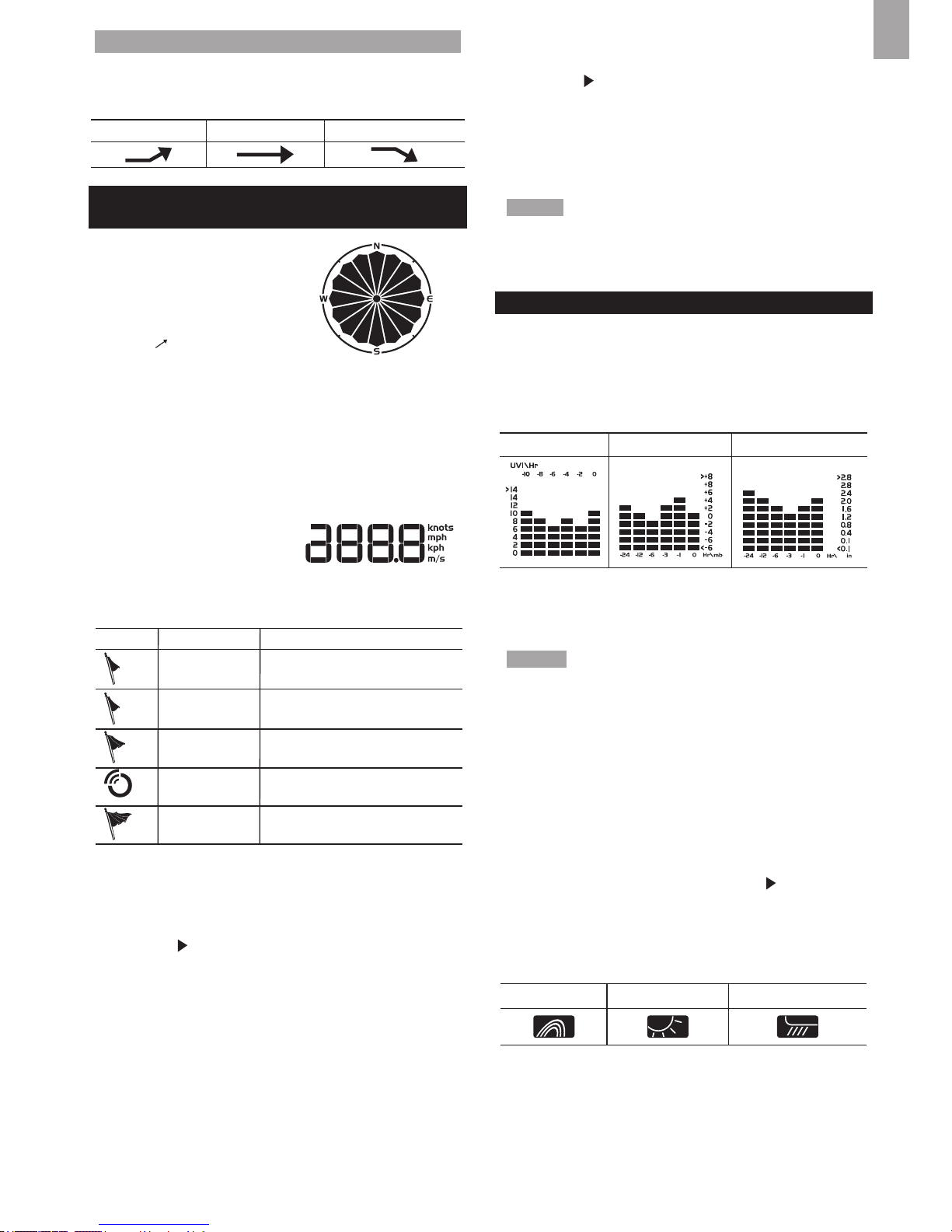
WIND CHILL / DIRECTION / SPEED
The base station provides
wind speed and wind direction
information.
To read the wind direction nd
the compass point the
is
pointing to.
The timestamp records the date and time when storing
the wind speed readings.
To select the wind speed unit:
Press UNIT to switch between:
• Metres per second (m / s)
• Kilometers per hour (kph)
• Miles per hour (mph)
• Knots (knots)
The wind level is shown by a series of icons:
ICON LEVEL DESCRIPTION
N/A <2 mph (<4km/h)
Light 2-8 mph (3~13 km/h)
Moderate 9-25 mph (~14-41 km/h)
Strong 26-54 mph (~42-87 km/h)
Storm >55 mph (>88 km/h)
T o view the maximum wind speed and minimum wind
chill readings:
1. Press SELECT to navigate to the Wind Speed / Wind
Direction / Wind Chill Area.
will show next to the
Area.
2. Press MAX / MIN to toggle between current / MAX
wind speed and current / MIN wind chill displays.
The timestamp is displayed accordingly in the Clock
Area.
T o clear minimum wind chill reading / maximum wind
speed reading:
1. Press SELECT to navigate to the Wind Speed / Wind
Direction / Wind Chill Area.
will show next to the
Area.
2. Press MAX / MIN repeatedly until minimum wind
chill reading or maximum wind speed reading is
displayed.
3. Press and hold MAX / MIN to clear the readings.
NOTE The wind chill factor is based on the combined
effects of temperature and wind speed. Displayed wind
chill is calculated solely from Channel 1 sensors.
UVI / BAROMETER / RAINFALL
The weather station works with one UV sensor and
one rain gauge. The station is capable of storing and
9
EN
displaying the hourly history data for the last 10 hours
of UV index, and 24 hours of rainfall and barometric
pressure readings.
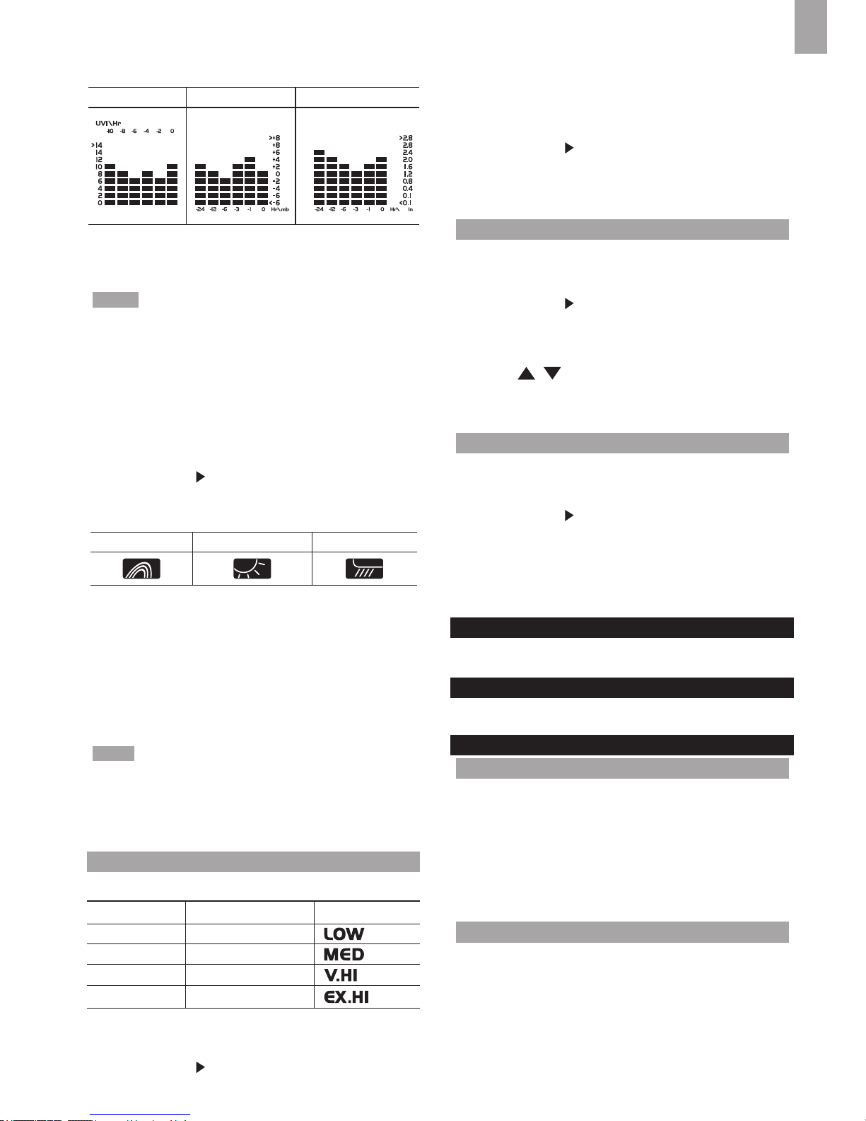
UVI BAROMETER RAINFALL
The bar chart display shows the current and historical
data for the UV index, barometric pressure and rainfall
readings.
NOTE The number shown in the horizontal axis (Hr)
indicates how long ago each measurement was taken
(e.g. 3 hours ago, 6 hours ago, etc.). The bar represents
the measurement taken for that specic 1 hour period.
E.g., if it is 10:30 pm now, the bar plotted directly above
-1 shows the reading recorded from 9 to 10 pm and
-6 shows the reading recorded earlier in the evening,
between 4pm-5pm.
To view the UV / Barometer / Rainfall readings:
1. Press SELECT to navigate to the UV / Barometer /
Rainfall Area.
will show next to the Area.
2. Press MODE to toggle between UVI / Barometer /
Rainfall readings. The corresponding icon will appear:
BAROMETER UVI RAINFALL
T o select the measurement unit for the barometer or
rainfall readings:
In the UV / Barometer / Rainfall Area, press UNIT to
switch between:
• Barometer: Millimeters of mercury (mmHg), inches
of mercury (inHg), millibars per hectopascal (mb).
• Rainfall: Millimeters (mm), inches (in), recorded for
that hour.
NOTE As the purpose of the bar graph is only to provide
a quick comparison between the records of the past 24
hours, the vertical axis cannot convert from inches to mm.
Therefore, changing the measurement unit will have no
effect on the bar graph display.
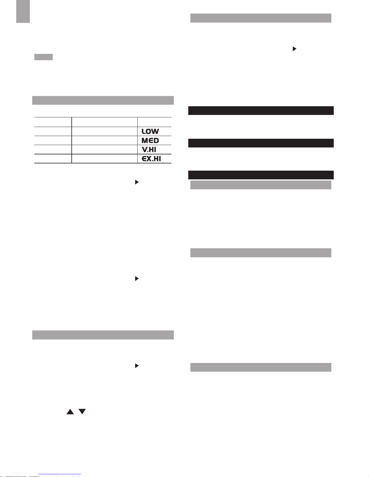
UV INDEX
The UV index levels are as follows:
UV INDEX DANGER LEVEL ICON
0-2 Low
3-5 Moderate
8-10 Very high
11 and above Extremely high
To view the maximum UV reading:
1. Press SELECT to navigate to the UVI / Barometer /
Rainfall Area.
will show next to the Area.
2. Press MODE repeatedly to select UV display.
3. Press MAX / MIN to toggle between current / MAX
UV index display.
The timestamp is displayed accordingly in the Clock
Area.
To clear maximum UV reading:
1. Press SELECT to navigate to the UVI / Barometer /
Rainfall Area.
will show next to the Area.
2. Press MODE repeatedly to select UV display.
3. Press and hold MAX / MIN to clear the readings.
BAROMETER
To set the altitude level compensation for the
Barometer readings:
1. Press SELECT to navigate to the UVI / Barometer /
Rainfall Area.
will show next to the Area.
2. Press MODE repeatedly to select Barometric
display.
3. Press and hold MODE to enter the altitude setting.
4. Press / to increase / decrease the setting value.
5. Press MODE to conrm the setting.
RAINFALL
To view the recorded rainfall of the current hour or
last 24 hours:
1. Press SELECT to navigate to the UVI / Barometer /
Rainfall Area.
will show next to the Area.
2. Press MODE repeatedly to select Rainfall display.
3. Press MAX / MIN repeatedly to toggle between
current, past 24 hour rainfall or accumulated rainfall
readings.
BACKLIGHT
Press LIGHT to activate the backlight for 5 seconds.
RESET
Press RESET to return to the default settings.
SPECIFICATIONS
BASE STATION
Dimensions
(L x W x H)
94 x 51 x 182.5 mm
(3.7 x 2.0 x 7.2 inches)
Weight 241 g (8.5 oz) without battery
Battery
3 x UM-3 (AA) 1.5V
AC/DC Adapter Input: 120 V, 60 Hz 50 mA
Output: DC 5V, 100 mA
INDOOR BAROMETER
Barometer unit mb, inHg and mmHg
Measuring range 700 – 1050mb/hPa
Accuracy +/- 10 mb/hPa
Altitude setting Sea level
User setting for compensation
Weather display Sunny, Partly Cloudy, Cloudy,
Rainy and Snowy

10
EN
Memory Historical data and bar chart for
last 24hrs
INDOOR TEMPERATURE
Temp. unit °C / °F
Displayed range -5ºC ~ 50ºC (23ºF ~ 122ºF)
Operating range 0°C to 50°C (32°F to 122°F)
Accuracy 0°C - 40°C: +/- 1°C (+/- 2.0°F)
40°C - 50°C: +/- 2°C (+/- 4.0°F)
Memory Current, Min and Max temp.
Dew Point w/ Min and Max
INDOOR RELATIVE HUMIDITY
Displayed range 2% to 98%
Operating range 25% to 90%
Accuracy 25% - 40%: +/- 7%
40% - 80%: +/- 5%
80% - 90%: +/- 7%
Memory Current, Min and Max
RADIO-CONTROLLED / ATOMIC CLOCK
Synchronization Auto or disabled
Clock display HH:MM:SS
Hour format 12hr AM/PM or 24hr
Calendar DD/MM or MM/DD
Weekday in 5
languages
(E, D, F, I, S, R)
REMOTE WIND SENSOR UNIT
Dimensions
(L x W x H)
178 x 76 x 214 mm
(7 x 3 x 8.4 inches)
Weight 100 g (0.22 lbs) without battery
Wind speed unit m/s, kph, mph, knots
Speed accuracy 2 m/s ~ 10 m/s (+/- 3 m/s)
10 m/s ~ 56 m/s (+/- 10%)
Direction accuracy 16 positions
Transmission of
wind speed signal
Approx. every 56 seconds
Memory Max wind speed
Battery 2 x UM-3 (AA) 1.5V batteries
OUTDOOR TEMPERATURE / HUMIDITY UNIT
Dimensions
(L x W x H)
92 x 60 x 20 mm
(3.6 x 2.4 x 0.79 in)
Weight 62 g (2.22oz) without battery
Humidity range 25% to 95%
Humidity accuracy 25% - 40%: +/- 7%
40% - 80%: +/- 5%
80% - 90%: +/- 7%
Temp. unit °C / °F
Temperature
outdoor range
-30°C to 60°C (-22°F to 140°F)
Temperature
accuracy
-20°C to 0°C:
+/- 2.0°C (+/- 4.0°F)
0°C to 40°C:
+/- 1.0°C (+/- 2.0°F)
40°C to 50°C:
+/- 2.0°C (+/- 4.0°F)
50°C to 60°C:
+/- 3.0°C (+/- 6.0°F)
RF frequency 433MHz
Range Up to 100 meters (328 feet)
with no obstructions
Transmission Approx. every 102 seconds
Channel no. 3
Batteries 2 x UM-4 (AAA) 1.5V
REMOTE RAIN GAUGE
Dimensions
(L x W x H)
114 x 114 x 145 mm
(4.5 x 4.5 x 5.7 inches)
Weight 241 g (0.54 lbs) without battery
Rainfall unit Mm and in
Range 0 mm – 9999 mm
Accuracy < 15 mm: +/- 1 mm
15 mm to 9999 mm: +/- 10%
Memory Past 24hrs, hourly from last
memory reset
Battery 2 x UM-3 (AA) 1.5V
PRECAUTIONS
• Do not subject the unit to excessive force, shock,
dust, temperature or humidity.
• Do not cover the ventilation holes with any items such
as newspapers, curtains etc.
• Do not immerse the unit in water. If you spill liquid
over it, dry it immediately with a soft, lint-free cloth.
• Do not clean the unit with abrasive or corrosive materials.
• Do not tamper with the unit’s internal components.
This invalidates the warranty.
• Only use fresh batteries. Do not mix new and old
batteries.
• Images shown in this manual may differ from the
actual display.
• When disposing of this product, ensure it is collected
separately for special treatment and not as household
waste.
• Placement of this product on certain types of wood
may result in damage to its nish for which Oregon
Scientic will not be responsible. Consult the furniture
manufacturer's care instructions for information.
• The contents of this manual may not be reproduced
without the permission of the manufacturer.
• Do not dispose old batteries as unsorted municipal
waste. Collection of such waste separately for special
treatment is necessary.
• Please note that some units are equipped with a
battery safety strip. Remove the strip from the battery
compartment before rst use.
11
EN
NOTE The technical specications for this product and
the contents of the user manual are subject to change
without notice.
NOTE Features and accessories will not be available in
all countries. For more information, please contact your
local retailer. To download an electronic version of the
usermanual, please visit
http://global.oregonscientic.com/customerSupport.php.
ABOUT OREGON SCIENTIFIC
Visit our website www.oregonscientic.com to learn more
about Oregon Scientic products.
For any inquiry, please contact our Customer Services at
info@oregonscientic.com.
Oregon Scientic Global Distribution Limited reserves
the right to interpret and construe any contents, terms
and provisions in this user manual and to amend it, at
its sole discretion, at any time without prior notice. To
the extent that there is any inconsistency between the
English version and any other language versions, the
English version shall prevail.
EU DECLARATION OF CONFORMITY
Hereby, IDT Technology Limited, declares that this
Pro Colour Weather Station (models: WMR86NS
/ WMR86NSA) is in compliance with the essential
requirements and other relevant provisions of Directive
2014/53/EU. A copy of the signed and dated Declaration of
Conformity is available on request via our Oregon Scientic
Customer Service.
COUNTRIES RED APPROVED COMPLIED
All EU countries, Switzerland
and Norway
N
CH
FCC STATEMENT
This device complies with Part 15 of the FCC Rules.
Operation is subject to the following two conditions: (1) This
device may not cause harmful interference, and (2) This
device must accept any interference received, including
interference that may cause undesired operation.
WARNING Changes or modications not expressly
approved by the party responsible for compliance could
void the user’s authority to operate the equipment.
NOTE This equipment has been tested and found
to comply with the limits for a Class B digital device,
pursuant to Part 15 of the FCC Rules. These limits
are designed to provide reasonable protection against
harmful interference in a residential installation.
This equipment generates, uses and can radiate radio
frequency energy and, if not installed and used in
accordance with the instructions, may cause harmful
interference to radio communications. However, there is
no guarantee that interference will not occur in a particular
installation. If this equipment does cause harmful
interference to radio or television reception, which can
be determined by turning the equipment off and on, the
user is encouraged to try to correct the interference by
one or more of the following measures:
• Reorient or relocate the receiving antenna.
• Increase the separation between the equipment and
receiver.
• Connect the equipment into an outlet on a circuit
different from that to which the receiver is connected.
• Consult the dealer or an experienced radio / TV
technician for help.
DECLARATION OF CONFORMITY
The following information is not to be used as contact
for support or sales. Please visit our website at http://
us.oregonscientic.com/service/ for all enquiries.
We
Name: Oregon Scientic, Inc.
Address: Centerpointe CENTER
5 Centerpointe DRIVE, SUITE 400
LAKE OSWEGO, OREGON 97035
Telephone No.: 971-204-0378
declare that the product
Product No.: WMR86NS / WMR86NSA
Product Name: Pro Colour Weather Station
Manufacturer: IDT Technology Limited
Address: Block C, 9/F, Kaiser Estate,
Phase 1, 41 Man Yue St.,
Hung Hom, Kowloon,
Hong Kong
is in conformity with Part 15 of the FCC Rules. Operation
is subject to the following two conditions: 1) This device
may not cause harmful interference. 2) This device must
accept any interference received, including interference
that may cause undesired operation.
DISPOSAL INFORMATION FOR USERS
Pursuant to and in accordance with Article 14 of
the Directive 2012/19/EU of the European
Parliament on waste electrical and electronic
equipment (WEEE), and pursuant to and in
accordance with Article 20 of the
Directive 2006/66/EC of the European Parliament on batteries and accumulators and waste batteries.
The barred symbol of the rubbish bin shown on the equipment
indicates that, at the end of its useful life, the product must be
collected separately from other waste.
Please note that the batteries/rechargeable batteries must
be removed from the equipment before it is given as waste. To
remove the batteries/accumulators refer to the
specications in the user manual. Therefore, any
products that have reached the end of their useful life must be given to waste disposal centers
specializing in separate collection of waste electrical and
electronic equipment, or given back to the dealer when
purchasing a new WEEE, pursuant to and in accordance
with Article 14 as implemented in the country.

12
EN
The adequate separate collection for the subsequent
start-up of the equipment sent to be recycled, treated
and disposal of in an environmentally compatible way
contributes to preventing possible negative effects on
the environment and health and optimizes the recycling
and reuse of components making up the apparatus.
Abusive disposal of the product by the user involves
application of the administrative sanctions according to
the laws in force.

1
IT
Color Stazione meteo professionale
Modello: WMR86NS / WMR86NSA
MANUALE PER L’UTENTE
INDICE
Introduzione ..............................................................1
Contenuto della confezione
.....................................1
Unità principale
...................................................1
Anemometro
........................................................1
Termoigrometro
...................................................2
Pluviometro
.........................................................2
Accessori e sensori
..................................................2
Panoramica
...............................................................2
Vista anteriore
.....................................................2
Vista posteriore
...................................................2
Display LCD
........................................................3
Anemometro
.......................................................4
Pluviometro
.........................................................4
Sensore termoigrometro
.....................................4
Operazioni preliminari
..............................................4
Installazione dell’anemometro
............................4
Installazione del sensore termoigrometro
...........4
Installazione del pluviometro
...............................4
Installazione dell’ unita’ principale
.......................5
Connetti l’adattatore CA
......................................5
Verica del collegamento
........................................5
Anemometro
.......................................................5
Sensore termoigrometro
....................................6
Pluviometro
.........................................................6
Montaggio / collocazione dei sensori
.....................6
Anemometro
.......................................................6
Sensore termoigrometro
....................................6
Pluviometro
.........................................................6
Ricezione dell’ora
.....................................................7
Orologio e calendario
...............................................7
Fasi lunari
..................................................................8
Funzione di alternanza automatica
Delle informazioni visualizzate
................................8
Previsioni meteorologiche
.......................................8
Temperatura e umidità
.............................................8
Tendenza di temperatura e umidità
.....................8
Indice di raffreddamento / Direzione
/ Velocità del vento
...................................................9
Indice UV / Barometro / Precipitazioni
....................9
Indice UV
...........................................................10
Barometro
.........................................................10
Precipitazioni
.....................................................10
Retroilluminazione
.................................................10
Funzione Reset
.......................................................10
Speciche tecniche
................................................10
Precauzioni
............................................................. 11
Informazioni su Oregon Scientic
........................12
Dichiarazione di conformita’ UE
............................12
Informazione Agli Utenti
........................................12
INTRODUZIONE
Grazie per aver scelto la Stazione meteo professionale
(WMR86NS / WMR86NSA) di Oregon Scientic
TM
.
L’unità principale è compatibile con sensori addizionali
opzionali.
I sensori con questo logo
sono compatibili con
questa unità.
NOTA Si consiglia di tenere questo manuale a portata di
mano durante l’utilizzo del prodotto. Il manuale contiene
pratiche istruzioni dettagliate, dati tecnici e avvertenze
che è necessario conoscere.
CONTENUTO DELLA CONFEZIONE
UNITÀ PRINCIPALE
ANEMOMETRO
1 sensore di
direzione del vento (1
segnavento sopra e 1
anemometro sotto)
1 connettore
per il sensore
2 batterie UM-3
/ AA da 1,5V
4 viti di
tipo A
1 bulloni
rotondi a U
1 unità principale
3 batterie AA
UM-3 da 1,5 V
1x Adattatore
CA/CC di
alimentazione
2
IT
TERMOIGROMETRO
PLUVIOMETRO
ACCESSORI E SENSORI
Questo prodotto può funzionare con un numero massimo
di 3 sensori contemporaneamente per rilevare la
temperatura esterna, l’umidità relativa e i dati sui raggi UV
(con sensore remoto opzionale) in diverse posizioni.
È possibile acquistare separatamente sensori remoti
senza li aggiuntivi come quelli sottoelencati. Per ulteriori
informazioni, rivolgersi al proprio rivenditore.*
• Pannello solare STC800 collegabile all’anemometro
e al termoigrometro
• Termoigrometro THGR800 (3 canali)
• Termoigrometro THGR810 (10 canali)
• Sensore raggi UV UVN800
• Sensore per piscina THWR800
* Caratteristiche e accessori non disponibili in tutti i
paesi.
PANORAMICA
VISTA ANTERIORE
31
2
4
5
1. MODE: consente di passare alle diverse modalità
di visualizzazione / impostazioni, di impostare l'ora
e l’altitudine e di attivare la ricerca automatica dei
canali
2. MAX/MIN: consente di accedere alle rilevazioni
memorizzate delle massime / minime e di
cancellarle
3. SELECT: consente di spostarsi tra le diverse aree
4. LIGHT: consente di attivare la retroilluminazione
5. / : consente di aumentare / diminuire i valori
dell’impostazione selezionata e di alternare i canali
interno ed esterno
VISTA POSTERIORE
1
2
4
3
5
6
1. RESET: ripristina i valori predeniti dell’unità
2. UNIT: consente di selezionare l’unità di misura
3. SEARCH: cerca i sensori o il segnale per l’orologio
radiocontrollato
4. Selettore EU / UK: consente di selezionare il
segnale di radiocontrollo di interesse (solo il modello
WMR86NS)
5. Vano batterie
6. Ingresso per l’alimentatore
2 batterie AAA
UM-4 da 1,5V
1 staffa per
montaggio a
parete
1 sensore di
temperatura e
umidità
2 batterie UM-
3 / AA
4 viti di
tipo B
1 raccoglitore di
acqua piovana
6 ranelle
1 x supporto
da tavolo
3
IT
DISPLAY LCD
1
2
A
B
C
D
E
1. : batterie dell’unità principale in esaurimento
2. Previsioni meteorologiche
A. Area temperatura / indice di calore
B. Area umidità / punto di rugiada
C. Area velocità del vento / direzione del vento / indice
di raffreddamento
D. Area indice UVI / barometro / precipitazioni
E. Area orologio / calendario / fasi lunari
A Area temperatura / indice di calore
1
3
2
5
6
7
4
1. Vengono visualizzate la temperatura e l’umidità interna
/ esterna del canale visualizzato
2. Batteria del sensore esterno in esaurimento
3. Icona dell’area selezionata
4. Indica che è visualizzata la temperatura MAX / MIN
5. Tendenza della temperatura
6. Rilevazione della temperatura (°C / °F)
7. Indice di calore
B Area umidità / punto di rugiada
1
2
5
3
4
1. Indica che sono visualizzati il livello del punto di
rugiada e la temperatura
2. Indica che sono visualizzati l’umidità MAX / MIN e il
livello del punto di rugiada
3. Tendenza dell’umidità
4. Rilevazione dell’umidità
5. Icona dell’area selezionata
C Area velocità del vento / direzione del vento /
indice di raffreddamento
3
1
2
5
6
4
8
7
1. Visualizzazione memoria velocità MAX del vento
2. Lettura di velocità del vento (m/s, nodi, kph or mph)
3. Visualizzazione di batteria scarica del sensore vento
esterno
4. Indicatore di velocità del vento (AVG/GUST)
5. Indicatore del livello di velocità del vento
6. Descrizione del livello di velocità del vento
7. Visualizzazione del vento freddo minimo
8. Indicatore di direzione dl vento
D Area indice UVI / barometro / precipitazioni
1
2
3
5
4
7
8
6
1. Barometro/UVI/Indicatore di lettura di piovosità
2. UVI esterno/Visualizzazione di batteria scarica del
sensore pioggia
3. ACCUM/PAST 24 HRS – visualizza i dati storici delle
24 ore passate relativi alla pioggia accumulata
4. Barometro/UVI/letture di piovosità
5. Indicatore del livello UVI
6. Pressione barometrica/UVI/Visualizzazione delle
unità di piovosità
7. Visualizzazione MAX barometro/UVI/pioggia
8. Pressione barometrica/UVI/Visualizzazione del
graco della cronologia di piovosità
E Area orologio / calendario / fase lunare
1
2
3
4
5
1. : indicatore della ricezione del segnale orario
2. Visualizzazione della memoria temporale
3. Fuso orario
4. Fase lunare
5. Ora / data / calendario
4
IT
ANEMOMETRO
1. Direzione del vento
2. Involucro del segnavento
3. Anemometro
4. Ingresso alimentazione solare
PLUVIOMETRO
Base e imbuto:
1. Pluviometro
2. Vano batterie
3. Pulsante RESET
1. Imbuto
2. Indicatore
SENSORE TERMOIGROMETRO
1. Indicatore LED
2. Foro RESET
3. °C / °F: consente di selezionare l’unità di misura della
temperatura
4. Levetta CHANNEL per la assegnazione del canale
5. Vano batterie
OPERAZIONI PRELIMINARI
NOTA Inserire le batterie nei sensori remoti, dopo
averle inserite nella stazione base, rispettando le
polarità (+/-).
NOTA Utilizzare batterie alcaline in caso di uso
prolungato e batterie al litio in ambienti con temperature
inferiori allo 0.
INSTALLAZIONE DELL’ANEMOMETRO
L’anemometro rileva la velocità e la direzione del
vento.
Il sensore funziona a batterie. Esso è in grado di
trasmettere dati all’unità principale senza l’utilizzo di li,
entro un campo d’azione di circa 100 metri.
Inserimento delle batterie:
1
2
1. Svitare con cura l’anemometro dal sensore del
vento.
2. Inserire le batterie rispettando le polarità (+/-) e
riposizionare l’anemometro. Premere RESET dopo
ogni sostituzione di batteria.
INSTALLAZIONE DEL SENSORE
TERMOIGROMETRO
L’unità principale è in grado di ricevere dati da un numero
massimo di 3 sensori remoti, posizionati su tre diversi
canali. La selezione del canale sul sensore remoto deve
essere effettuata tramite l’apposito selettore posto nel
vano batterie.
Impostazione del sensore remoto:
1. Aprire il coperchio della batteria facendolo scorrere.
2. Utilizzare il commutatore di canale per selezionare
un canale (1, 2, 3). Vericare di utilizzare un canale
diverso per ciascun sensore.
3. Inserire le batterie facendo corrispondere i poli (+/-).
4. Premere RESET dopo ogni sostituzione di batteria.
5. Chiudere il coperchio della batteria.
INSTALLAZIONE DEL PLUVIOMETRO
Il pluviometro effettua rilevazioni sul livello delle
precipitazioni. Il sensore è in grado di trasmettere in
maniera remota i dati all’unità principale.
Installazione del pluviometro:
1
2
3
4
1
5
2
3
4
CF
5
IT
1. Togliere le viti e far scorrere la copertura verso
l’alto.
2. Inserire le batterie (2 di tipo UM-3 / AA), rispettando le
polarità (+/-). Premere RESET dopo ogni sostituzione
di batteria.
3. Rimuovere il nastro adesivo che blocca l’imbuto.
INSTALLAZIONE DELL’ UNITA’ PRINCIPALE
NOTA Inserire le batterie nei sensori remoti, dopo
averle inserite nell’unità principale, rispettando le polarità
(+ e -).
1. Far scorrere la copertura del vano batterie no ad
aprirlo.
2. Inserire le batterie, rispettando le polarità indicate (+ / -).
3. Premere RESET dopo ogni sostituzione di batteria.
4. Chiudere il coperchio del vano batterie.
NOTE Non utilizzare batterie ricaricabili. Con questo
prodotto si consiglia di utilizzare batterie alcaline per
prestazioni prolungate.
NOTE
Non esporre le batterie ad eccessive fonti di
calore, quali sole o fuoco.
L’icona dell’indicatore della batteria
può apparire
nelle seguenti aree:
AREA SIGNIFICATO
Area previsioni
meteorologiche
La batteria della stazione è in
esaurimento.
Area temperatura
ed umidità
Il canale visualizzato indica il
sensore esterno la cui batteria è in
esaurimento.
Area velocità del
vento / direzione
del vento / Indice
di raffreddamento
La batteria dell’anemometro è in
esaurimento.
Area indice UV
/ barometro /
precipitazioni
La batteria del sensore UV / del
pluviometro è in esaurimento.
CONNETTI L’ADATTATORE AC
Connettere il jack dell’alimentatore alla stazione base,
quindi collegare l’adattatore CA/CC a una presa CA
standard.
NOTA
• Le batterie sono solo per l’uso di back-up. Collegare,
per cui, sempre l’apparecchio alla presa
della rete elettrica tramite l’adattatore AC/DC.
• Assicurarsi che l’adattatore non sia ostruito e sia
facilmente accessibile all’unità.
• esposti ad acqua. Nessun oggetto riempito di liquido,
come vasi, deve essere posto sulla stazione base e
l’adattatore.
• Per disconnettere completamente
l’alimentazione,scollegare l’adattatore dalla presa
di corrente.
VERIFICA DEL COLLEGAMENTO
Prima di procedere all’installazione esterna dei sensori,
vericare la comunicazione con la stazione base.
ANEMOMETRO
Premere SELECT nché l’icona dell’area selezionata
non si trova nella zona di visualizzazione al centro
del display.
• Velocità del vento: Ruotare delicatamente la ruota a
coppette e confermare la rilevazione numerica sulla
stazione base, ad es.
.
6
IT
• Indicatore della direzione del vento. Cambiare la
direzione dell'indicazione del vento e vericare che
l'icona si sposti nella stessa direzione
.
SENSORE TERMOIGROMETRO
1. Premere SELECT nché l’icona dell’area selezionata
non si trova nella zona di visualizzazione nella parte
superiore del display.
2. Premere / per selezionare il canale 1 e
vericare la rilevazione numerica.
PLUVIOMETRO
1. Premere SELECT nché l’icona dell’area selezionata
non si trova nella zona di visualizzazione nella parte
inferiore del display.
2. Premere MODE nché non viene visualizzata l’icona
.
3. Inclinare l’imbuto raccoglitore del pluviometro diverse
volte e verificare la rilevazione numerica sulla
stazione base.
SUGGERIMENTO Se non viene visualizzata nessuna
lettura relativa a un sensore, tenere premuto SEARCH
sulla stazione base per avviare la ricerca di un sensore
senza li.
MONTAGGIO / COLLOCAZIONE DEI SENSORI
ANEMOMETRO
NOTA Il sensore deve inoltre essere collocato in uno
spazio aperto, lontano da alberi e da altre ostruzioni.
a
b
Fissare il connettore del sensore nel punto desiderato:
a. Allineare la parte posteriore del connettore del
sensore con un palo preesistente. Fissare inserendo
le estremità del bullone a U nei fori sul connettore del
sensore e assicurandolo con ranelle e bulloni.
OPPURE
b. Inserire 4 viti di tipo A nei fori del connettore del
sensore. Fissare saldamente in posizione, ad es. su
un recinto.
Far scorrere il segnavento
sull’estremità più piccola del
connettore del sensore.
IMPORTANTE Vericare che l’anemometro sia orientato
verso il nord per ottenere rilevazioni precise.
SENSORE TERMOIGROMETRO
150cm(5ft)
SUGGERIMENTO La collocazione ideale del sensore
è un luogo all’esterno dell’abitazione ad un’altezza non
inferiore a 1½ metri, dove possa essere protetto da
luce solare diretta o umidità per garantire una maggior
attendibilità delle rilevazioni.
Collocare il sensore nella posizione desiderata mediante il
foro per ssaggio a parete o con il supporto da tavolo.
PLUVIOMETRO
L’unità principale e il pluviometro devono essere
posizionati entro un campo effettivo di circa 100 metri in
uno spazio aperto.
Il pluviometro deve essere montato in posizione
orizzontale, a circa 1 metro dal terreno, in uno spazio
aperto, lontano da alberi e da altre ostruzioni, così da
consentire alla pioggia di cadere in modo naturale,
garantendo una rilevazione precisa.
7
IT
Verica dell’orizzontalità:
Versare delle gocce d’acqua sulla croce presente sulla
base dell’imbuto per vericarne l’orizzontalità.
1
23
4
Se il pluviometro è orizzontale, l’acqua si depositerà al
centro della croce.
Se l’acqua rimane sui punti da 1 a 4, il pluviometro non
è orizzontale.
Se necessario, regolare il livello agendo sulle viti poste sui
piedini di appoggio, come mostrato nella illustrazione.
NOTA Per ottenere i migliori risultati, vericare che la
base sia orizzontale per consentire il massimo scolo della
pioggia raccolta.
SUGGERIMENTO Premere il pulsante RESET sulla
stazione di base per cancellare tutti i dati di verica.
RICEZIONE DELL’ORA
Questo prodotto è progettato per sincronizzare
automaticamente il proprio orologio-calendario quando
si trova nel raggio di un segnale di radiocontrollo:
WMR86NS:
• EU: segnale DCF-77: entro 1500km da Francoforte,
Germania.
• UK: segnale MSF-60: entro 1500km da Anthorn,
Inghilterra.
WMR86NSA:
• Segnale WWVB-60: entro 3200 km da Fort Collins,
Colorado.
Solo per il modello WMR86NS – spostare la levetta
EU / UK sull’impostazione corretta in base alla
propria posizione. Premere RESET ad ogni modica
dell’impostazione selezionata.
Quando è in corso la ricerca di un segnale, l’icona della
ricezione lampeggia. Se il segnale è debole, possono
occorrere no a 24 ore per riceverne uno valido.
L’icona indica lo stato della ricezione del segnale
dell’orologio.
ICONA SIGNIFICATO
L’ora è sincronizzata.
La ricezione del segnale è forte
L’ora non è sincronizzata.
La ricezione del segnale è debole
Per attivare (e forzare la ricerca di segnale) /
disattivare la ricezione radio (sincronizzazione
dell’orologio):
1. Premere SELECT per passare all’Area orologio /
calendario / fasi lunari. L’icona
lampeggerà accanto
all’area.
2. Tenere premuto SEARCH.
L’icona
appare quando è attiva la funzione di ricezione
del segnale di radiocontrollo.
NOTA Per una migliore ricezione, il prodotto deve
essere collocato su una supercie piana e non metallica,
vicino a una nestra, lontano da elettrodomestici, e non
deve essere spostata quando è in corso la ricerca di
segnale.
OROLOGIO E CALENDARIO
Per impostare l’orologio manualmente:
(È necessario impostare l’orologio e il calendario solo se
è stata disattivata la ricezione radio dell’ora)
1. Premere SELECT per passare all’Area orologio.
L’icona
lampeggerà accanto all’area.
2. Tenere premuto MODE per modicare le impostazioni
dell’orologio. Il valore da impostare lampeggerà.
3. Premere / per aumentare / diminuire il valore
dell’impostazione.
4. Premere MODE per confermare.
5. Ripetere le fasi da 3 a 4 per impostare differenza di
fuso orario (+ / -23 ore), formato dell’ora 12 / 24 ore,
ora, minuto, anno, formato data / mese, mese, data
e lingua del giorno della settimana.
NOTA Se si immette il valore +1 nell’impostazione
del fuso orario, verrà visualizzata la propria ora locale
più un’ora.
Se ci si trova negli Stati Uniti (solo per il modello
WMR86NSA) impostare l’orologio come segue:
la zona del Pacico la zona delle montagne
la zona Centrale la zona Orientale
NOTA Il giorno della settimana è disponibile in inglese
(E), tedesco (D), francese (F), italiano (I), spagnolo (S)
e russo (R).
Per modicare la visualizzazione dell’orologio:
1. Premere SELECT per passare all’Area orologio.
L’icona
lampeggerà accanto all’area.
8
IT
2. Premere MODE per scorrere tra le opzioni:
• Orologio con secondi
• Orologio con giorno della settimana
• Calendario
FASI LUNARI
Perché questa funzione sia attiva, deve essere impostato
il calendario (v. il paragrafo Orologio e calendario).
Luna nuova Luna piena
Falce di luna
crescente
Luna calante
Primo quarto Ultimo quarto
Luna crescente
Falce di luna
calante
FUNZIONE DI ALTERNANZA AUTOMATICA
DELLE INFORMAZIONI VISUALIZZATE
Per attivare la funzione di alternanza automatica
delle informazioni visualizzate relative a temperatura
e umidità esterna:
1. Premere SELECT per passare all’Area Temperatura
e umidità. L’icona
lampeggerà accanto all’area.
2. Tenere premuto MODE per attivare la funzione
automatica. I dati interni ed esterni si alterneranno
automaticamente sul display.
3. Premere un tasto qualsiasi ad eccezione del tasto
LIGHT per interrompere la ricerca automatica.
NOTA Il canale 1 viene usato per il sensore di
temperatura e umidità esterne. I sensori aggiuntivi di
temperatura e umidità possono utilizzare altri canali.
PREVISIONI METEOROLOGICHE
La visualizzazione delle previsioni del tempo sulla parte
superiore del display si riferisce alle successive 12-24
ore, entro un raggio di 30-50 km (19-31 miglia).
Area previsioni meteorologiche
ICONA DESCRIZIONE
Sereno
Parzialmente nuvoloso
Nuvoloso
Pioggia
Neve
TEMPERATURA E UMIDITÀ
La stazione meteorologica indica le rilevazioni interne
ed esterne di:
1. Temperatura / umidità relativa (corrente / massima /
minima)
2. Linea della tendenza
3. Livello del punto di rugiada/Indice di calore
La stazione può collegarsi ad un numero massimo di 3
sensori remoti.
NOTA Il canale 1 è dedicato alla temperatura e
all’umidità esterna.
indica a quale sensore remoto appartengono i dati
visualizzati.
L’icona
appare quando vengono visualizzati i dati
interni.
La memoria temporale registra data e ora al momento
dell’archiviazione in memoria delle rilevazioni di
temperatura e umidità.
Per selezionare l’unità di misura della temperatura:
Premere UNIT per selezionare °C / °F.
NOTA L’unità di tutte le visualizzazioni della temperatura
verrà modicata simultaneamente.
Visualizzazione delle rilevazioni della temperatura
(temperatura corrente / minima / massima)
1. Premere SELECT per passare all’Area temperatura.
L’icona
lampeggerà accanto all’area.
2. Premere / per selezionare il canale.
3. Premere ripetutamente MODE per passare dalla
visualizzazione della temperatura all’indice di calore
e viceversa.
4. Premere MAX / MIN per alternare le visualizzazioni
corrente / MAX / MIN.
Visualizzazione delle rilevazioni dell’umidità (umidità,
punto di rugiada):
1. Premere SELECT per passare all’Area umidità.
L’icona
lampeggerà accanto all’area.
2. Premere / per selezionare il canale.
3. Premere ripetutamente MODE per alternare le
visualizzazioni di umidità e punto di rugiada.
4. Premere MAX / MIN per alternare le visualizzazioni
corrente / MAX / MIN.
Il riferimento temporale viene visualizzato conformemente
nell’Area orologio.
Per cancellare i dati memorizzati e il riferimento
temporale di temperatura, umidità e punto di rugiada:
Nell’Area temperatura o umidità, tenere premuto MAX /
MIN per cancellare le rilevazioni.
NOTA L’indice di calore fornisce un indicazione sul
calore avvertito in base alla temperature dell’aria e
relative umidità.
NOTA Il punto di rugiada indica a che temperatura si
forma la condensa.
9
IT
TENDENZA DI TEMPERATURA E UMIDITÀ
Le linee di tendenza vengono visualizzate accanto alle
rilevazioni di temperatura e umidità. La tendenza viene
indicata come segue:
IN AUMENTO STABILE IN DIMINUZIONE
INDICE DI RAFFREDDAMENTO / DIREZIONE
/ VELOCITÀ DEL VENTO
L’unità principale fornisce
informazioni sulla velocità
e sulla direzione del vento.
Per leggere la direzione del
vento, trovare il punto della
bussola
indicato da.
La memoria temporale registra la data e l’ora al momento
dell’archiviazione in memoria delle rilevazioni relative alla
velocità del vento.
Per selezionare l’unità di misura della velocità del
vento:
Premere UNIT per alternare:
• Metri al secondo (m / s)
• Kilometri orari (kph)
• Miglia orarie (mph)
• Nodi (knots)
L’intensità del vento viene visualizzata mediante una
serie di icone:
ICONA INTENSITÀ DESCRIZIONE
N/A <2 mph (<4km/h)
Leggera 2-8 mph (3~13 km/h)
Moderata 9-25 mph (~14-41 km/h)
Forte 26-54 mph (~42-87 km/h)
Tempesta >55 mph (>88 km/h)
Visualizzazione della velocità massima del vento e
dell’indice di raffreddamento minimo:
1. Premere SELECT per passare all’Area velocità del
vento / direzione del vento e indice di raffreddamento.
L’icona
lampeggerà accanto all’area.
2. Premere MAX / MIN per alternare le visualizzazioni
di velocità del vento corrente / MAX e di indice di
raffreddamento corrente / MIN.
Il riferimento temporale viene visualizzato conformemente
nell’Area orologio.
Cancellazione delle rilevazioni dell’indice di
raffreddamento minimo e della velocità massima
del vento:
1. Premere SELECT per passare all’Area velocità del
vento / direzione del vento e indice di raffreddamento.
L’icona
lampeggerà accanto all’area.
2. Premere ripetutamente MAX / MIN nché non viene
visualizzato l’indice di raffreddamento minimo o la
velocità del vento massima.
3. Tenere premuto MAX / MIN per cancellare le rilevazioni.
NOTA L’indice di raffreddamento è basato sulla
combinazione degli effetti di temperatura e velocità del
vento. L’indice di raf freddamento visualizzato è calcolato
unicamente in base ai sensori del Canale 1.
INDICE UV / BAROMETRO / PRECIPITAZIONI
La stazione meteorologica funziona con un sensore di
raggi UV (opzionale) e con un pluviometro. La stazione è
in grado di memorizzare e visualizzare i dati storici delle
ultime 10 ore relativamente all’indice UV, e delle ultime
24 ore relativamente alle rilevazioni delle precipitazioni
e della pressione barometrica.
UVI BAROMETRO PRECIPITAZIONI
Il grafico a barre indica i dati attuali e storici delle
rilevazioni relative a indice UV, pressione barometrica
e precipitazioni.
NOTA Il numero indicato sull’asse orizzontale (Hr)
indica quanto tempo prima è stata effettuata ciascuna
misurazione (es. 3 ore fa, 6 ore fa, etc.). La barra
rappresenta la misurazione rilevata in quello specico
lasso di tempo di 1 ora. Ad es., se ora sono le 22:30,
la barra che compare direttamente sopra -1 indica la
rilevazione registrata dalle 21 alle 22 e -6 indica la
rilevazione registrata prima, tra le 16 e le 17.
Per visualizzare le rilevazioni UV / barometro /
precipitazioni:
1. Premere SELECT per passare all’Area UV /
barometro / precipitazioni. L’icona
lampeggerà
accanto all’area.
2. Premere MODE per alternare le rilevazioni dell’indice
UV, del barometro e delle precipitazioni. Apparirà
l’icona corrispondente:
BAROMETRO UVI PRECIPITAZIONI
Per selezionare l’unità di misura per le rilevazioni del
barometro e delle precipitazioni:
Nell’Area UV / barometro / precipitazioni, premere UNIT
per alternare:
10
IT
• per il barometro: millimetri di mercurio (mmHg), pollici
di mercurio (inHg), millibar per ettopascal (mb).
• per le precipitazioni: millimetri (mm), pollici (in)
registrati in quell’ora.
NOTA Lo scopo del graco a barre è unicamente quello
di fornire un rapido confronto tra le rilevazioni delle
precedenti 24 ore; l’asse verticale non può passare da
pollici a mm. Pertanto, la modica dell’unità di misura non
avrà alcun effetto sulla visualizzazione del graco a barre.
INDICE UV
I livelli dell’indice UV sono i seguenti:
INDICE UV LIVELLO DI RISCHIO ICONA
0-2 Basso
3-5 Moderato
8-10 Molto alto
11 e oltre Estremamente alto
Visualizzazione della rilevazione UV massima:
1. Premere SELECT per passare all’Area UV /
barometro / precipitazioni. L’icona
lampeggerà
accanto all’area.
2. Premere ripetutamente MODE per selezionare la
visualizzazione UV.
3. Premere MAX / MIN per alternare le visualizzazioni
indice UV corrente / MAX.
La marca temporale viene visualizzata conformemente
nell’Area orologio.
Cancellazione della rilevazione massima UV:
1. Premere SELECT per passare all’Area UV /
barometro / precipitazioni. L’icona
lampeggerà
accanto all’area.
2. Premere ripetutamente MODE per selezionare la
visualizzazione UV.
3. Tenere premuto MAX / MIN per cancellare le
rilevazioni.
BAROMETRO
Per impostare la compensazione del livello di
altitudine per le rilevazioni barometriche:
1. Premere SELECT per passare all’Area UV /
barometro / precipitazioni. L’icona
lampeggerà
accanto all’area.
2. Premere ripetutamente MODE per selezionare la
visualizzazione della pressione.
3. Tenere premuto MODE per entrare nelle impostazioni
dell’altitudine.
4. Premere / per aumentare / diminuire il valore
dell’impostazione.
5. Premere MODE per confermare l’impostazione.
PRECIPITAZIONI
Visualizzazione delle rilevazioni registrate delle
precipitazioni correnti o delle ultime 24 ore:
1. Premere SELECT per passare all’Area UV /
barometro / precipitazioni. L’icona
lampeggerà
accanto all’area.
2. Premere ripetutamente MODE per selezionare la
visualizzazione delle precipitazioni.
3. Premere ripetutamente MAX / MIN per alternare tra
le precipitazioni correnti o delle ultime 24 ore passate
o le letture di piovosità accumulate.
RETROILLUMINAZIONE
Premere LIGHT per attivare la retroilluminazione per
5 secondi.
FUNZIONE RESET
Premere RESET per ripristinare le impostazioni
predenite dell’unità.
SPECIFICHE TECNICHE
UNITÀ PRINCIPALE
Dimensioni
(L x P x H)
94 x 51 x 182.5 mm
Peso 241g senza batteria
Alimentazione 3 batterie UM-3 (AA) da 1,5V
Adattatore CA/CC
Ingresso: 120 V, 60 Hz 50 mA
Uscita: CC 5V, 100 mA
BAROMETRO
Unità barometrica mb, inHg e mmHg
Campo di
misurazione
700 – 1050mb/hPa
Precisione +/- 10 mb/hPa
Impostazione
altitudine
Livello del mare
Impostazione dell’utente per
compensazione
Visualizzazione
informazioni
meteorologiche
Sereno, parzialmente nuvoloso,
nuvoloso, piovosa e neve
Memoria Dati storici e graco a barre
delle ultime 24 ore
TEMPERATURA INTERNA
Unità di misura
temperatura
°C / °F
Campo visualizzato -5°C a 50°C
Campo di
misurazione
0°C a 50°C
Precisione da 0°C a 40°C: +/- 1°C
da 40°C a 50°C: +/- 2°C

11
IT
Memoria Temperatura attuale, minima e
massima
Punto di rugiada con min e
max
UMIDITÀ RELATIVA INTERNA
Campo visualizzato da 2% a 98%
Campo di operatività da 25% a 90%
Precisione 25% - 40%: +/- 7%
40% - 80%: +/- 5%
80% - 90%: +/- 7%
Memoria Attuale, min. e max.
OROLOGIO RADIOCONTROLLATO
Sincronizzazione Automatica o disattivata
Visualizzazione ora HH:MM:SS
Formato ora 12h AM/PM oppure 24h
Calendario GG/MM o MM/GG
Giorno della
settimana in 6
lingue
(E, D, F, I, S, R)
ANEMOMETRO
Dimensioni
(L x P x H)
178 x 76 x 214 mm
Peso 100 g senza batteria
Unità di misura della
velocità del vento
m/s, kph, mph, knots (nodi)
Precisione della
velocità
2 m/s ~ 10 m/s (+/- 3 m/s)
10 m/s ~ 56 m/s (+/- 10%)
Indicazione della
direzione
16 posizioni
Trasmissione del
segnale di velocità
del vento
Ogni 56 secondi circa
Memoria Velocità max del vento
Alimentazione 2 batterie UM-3 (AA) da 1,5V
SENSORE TERMOIGROMETRO
Dimensioni
(L x P x H)
92 x 60 x 20 mm
(3.6 x 2.4 x 0.79”)
Peso 62 g senza batteria
Campo di
misurazione
dell’umidità
Da 25% a 95%
Precisione dell’
umidità
25% - 40%: +/- 7%
40% - 80%: +/- 5%
80% - 90%: +/- 7%
Unità di misura
temperatura
°C / °F
Campo di
misurazione
temp. esterna
da -30°C a 60°C
Precisione della
temperatura
da -20°C a 0°C: +/- 2.0°C
da 0°C a 40°C: +/- 1.0°C
da 40°C a 50°C: +/- 2.0°C
da 50°C a 60°C: +/- 3.0°C
Frequenza RF 433MHz
Campo di
trasmissione
Fino a 100 metri in campo
aperto
Trasmissione Ogni 102 secondi circa
Num. canali 3
Batterie 2 di tipo UM-4 (AAA) da 1,5V
PLUVIOMETRO REMOTO
Dimensioni
(L x P x H)
114 x 114 x 145 mm
Peso 241 g senza batteria
Unità di misura delle
precipitazioni
mm e in
Campo di
trasmissione
da 0 mm a 9999 mm
Precisione < 15 mm: +/- 1 mm
da 15 mm a 9999 mm: +/- 10%
Memoria Ultime 24 ore ogni ora
dall’ultimo azzeramento della
memoria
Alimentazione 2 batterie UM-3 (AA) da 1,5V
PRECAUZIONI
• Non sottoporre il prodotto a forza eccessiva, urti,
polvere, sbalzi eccessivi di temperatura o umidità.
• Non otturare i fori di aerazione con oggetti come
giornali, tende, etc.
• Non immergere l’unità in acqua. Se si versa del
liquido sul prodotto, asciugarlo immediatamente con
un panno morbido e liscio.
• Non pulire l’unità con materiali abrasivi o corrosivi.
• Non manomettere i componenti interni. In questo
modo si invalida la garanzia.
• Utilizzare solo batterie nuove. Non mescolare batterie
nuove con batterie vecchie.
• Le immagini del manuale possono differire dalla realtà.
• Al momento dello smaltimento del prodotto, utilizzare
la raccolta differenziata.
• Oregon Scientic declina ogni responsabilità per
eventuali danni alle niture causati dal posizionamento
del prodotto su determinati tipi di legno. Consultare le
istruzioni fornite dal fabbricante del mobile per ulteriori
informazioni.
• Il contenuto di questo manuale non può essere
ristampato senza l’autorizzazione del fabbricante.
• Non smaltire le batterie vecchie come riuto non
differenziato. È necessario che questo riuto venga
smaltito mediante raccolta differenziata per essere
trattato in modo particolare.
• Alcune unità sono dotate di una striscia di sicurezza
per le batterie. Rimuovere la striscia dal vano batterie
prima del primo utilizzo.
NOTA Le speciche tecniche del prodotto e il contenuto
del manuale per l’utente sono soggette a modiche
senza preavviso.
NOTA Caratteristiche e accessori non disponibili in tutti
i paesi. Per ulteriori informazioni, rivolgersi al proprio
rivenditore.Si prega di visitare il sito
http://global.oregonscientic.com/customerSupport.php
per scaricare una versione elettronica del manuale.
12
IT
INFORMAZIONI SU OREGON SCIENTIFIC
Per ulteriori informazioni sui prodotti Oregon Scientic,
visitate il nostro sito web www.oregonscientic.it.
Per richiedere informazioni, contattate il nostro Servizio
Clienti all’indirizzo info@oregonscientic.it.
Oregon Scientic Global Distribution Limited si riserva
il diritto di interpretare e denire eventuali contenuti,
termini e disposizioni contenuti in questo manuale per
l’utente e di modicarli, a sua esclusiva discrezione, in
qualsiasi momento e senza preavviso. Nella misura in
cui risultassero incongruenze tra la versione in inglese
e quelle in altre lingue, farà fede la versione in inglese.
DICHIARAZIONE DI CONFORMITA’ UE
Con la presente IDT Technology Limited dichiara che
questo Color Stazione meteo professionale (WMR86NS
/ WMR86NSA) è conforme ai requisiti essenziali ed alle
altre disposizioni pertinenti stabilite dalla direttiva 2014/53/
EU. Una copia rmata e datata della Dichiarazione di
Conformità è disponibile, su richiesta, tramite il servizio
clienti della Oregon Scientic.
PAESI CONFORMI ALLA DIRETTIVA RED
Tutti I Paesi UE, Svizzera
e Norvegia
N
CH
INFORMAZIONE AGLI UTENTI
Ai sensi dell’art.26 del Decreto Legislativo 14 marzo 2014, n. 49 “Attuazione della Direttiva 2012/19/
UE sui riuti di apparecchiature elettriche ed
elettroniche (RAEE)” ed ai sensi dell’art.22 del
Decreto Legislativo 188 del 20 novembre 2008 “Attuazione della direttiva 2006/66/CE concernente pile, accumu-
latori e relativi riuti “.
Il simbolo del cassonetto barrato riportato
sull’apparecchiatura o sulla sua confezione indica che
il prodotto alla ne della propria vita utile deve essere
raccolto separatamente dagli altri riuti per permetterne
un adeguato trattamento e riciclo.
Si ricorda che le pile/accumulatori devono essere rimosse
dall’apparecchiatura prima che questa sia conferita come
riuto. Per rimuovere le pile/ accumulatori fare riferimento
alle speciche indicazioni riportate nel manuale d’uso.
L’utente dovrà, pertanto, conferire gratuitamente
l’apparecchiatura e la pila giunta a ne vita agli idonei
centri comunali di raccolta
differenziata dei riuti elettrici ed elettronici, oppure
riconsegnarle al rivenditore secondo le seguenti modalità:
sia pile portatili sia apparecchiature di piccole dimensioni,
ovvero con almeno un lato esterno non superiore a 25
cm, è prevista la consegna gratuita senza obbligo di
acquisto presso i negozi con una supercie di vendita
delle apparecchiature elettriche ed elettroniche superiore
ai 400 mq. Per negozi con dimensioni inferiori, tale
modalità è facoltativa.
per apparecchiature con dimensioni superiori a 25 cm, è
prevista la consegna in tutti i punti di vendita in modalità
1 contro 1, ovvero la consegna al rivenditore potrà
avvenire solo all’atto dell’acquisto di un nuovo prodotto
equivalente, in ragione di uno a uno.
L’adeguata raccolta differenziata per l’avvio successivo
dell’apparecchiatura e delle pile/accumulatori dismessi
al riciclaggio, al trattamento e allo smaltimento
ambientalmente compatibile contribuisce ad evitare
possibili effetti negativi sull’ambiente e sulla salute e
favorisce il reimpiego e/o riciclo dei materiali di cui essi
sono composti.
Lo smaltimento abusivo di apparecchiature, pile ed
accumulatori da parte dell’utente comporta l’applicazione
delle sanzioni di cui alla corrente normativa di legge.
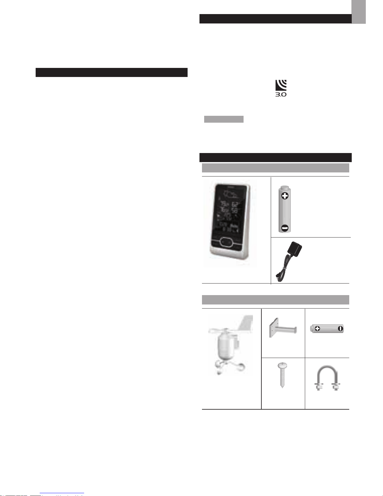
1
FR
Station Météo Professionnelle Ecran Couleur
Modèles : WMR86NS / WMR86NSA
MANUEL DE L’UTILISATEUR
TABLE DES MATIERES
Introduction ................................................................1
Contenu de l’emballage
............................................1
Station de base
....................................................1
Anémomètre/ girouette
........................................1
Sonde de température & d’humidité
...................2
Pluviomètre
..........................................................2
Accessoires - Capteurs.............................................2
Vue d’ensemble
.........................................................2
Face avant
...........................................................2
Face arrière
..........................................................2
Afchage LCD
......................................................3
Anémomètre-girouette
.........................................4
Pluviomètre
..........................................................4
Sonde de température & d’humidité extérieure
..4
Démarrage
..................................................................4
Installation de l’anémomètre
................................4
Installation du thermo hygromètre
.......................4
Réglage du pluviomètre
.......................................4
Installation de la station de base
..........................5
Connecter l’adaptateur electrique
........................5
Vérication de la connexion
.....................................5
Anémomètre-girouette
.........................................5
Sonde de température & d’humidité extérieure
...5
Pluviomètre
..........................................................6
Montage / Positionnement des sondes
...................6
Anémomètre-girouette
.........................................6
Sonde de température & d’humidité extérieure
...6
Pluviomètre
..........................................................6
Réception de l’horloge
..............................................7
Horloge / calendrier
...................................................7
Cycle lunaire
..............................................................7
Fonction auto balayage
............................................8
Prévisions météorologiques
....................................8
Température et humidité
...........................................8
Variation d’humidité et changement
de température
.....................................................8
Direction / Vitesse et refroidissement eolien
..........8
Précipitation / Barométre / Indice UV
......................9
Indice UV
.............................................................9
Barométre
..........................................................10
Précipitations
.....................................................10
Rétro - éclairage
......................................................10
Réinitialisation
.........................................................10
Spécications
..........................................................10
Précautions
..............................................................11
À propos d’Oregon Scientic
.................................11
Europe - Déclaration de conformité
......................11
Disposal Information For Users
.............................12
INTRODUCTION
Nous vous remercions d’avoir choisi cette Station
Météorologique (WMR86NS / WMR86NSA) de Oregon
Scientic
TM
.
Cette station est compatible avec d'autres capteurs. Si
vous désirez acheter des capteurs supplémentaires,
veuillez contacter votre revendeur local.
Les capteurs avec ce logo
sont compatibles avec
cet appareil.
REMARQUE Garder ce mode d’emploi à proximité
lors de l’utilisation de ce nouvel appareil. Il contient des
instructions pratiques complètes ainsi que des détails
techniques et des avertissement à connaître.
CONTENU DE L’EMBALLAGE
STATION DE BASE
ANEMOMETRE/ GIROUETTE
1 Capteur de vent (1
girouette au dessus
et 1 anémomètre en
dessous)
1 connecteur
de capteur
2 piles AA
UM-3 1.5V
4 vis
(Type A)
1 Ferrure
en U
1 station de base
3 x AA UM-3
1.5V batteries
1x Adaptateur
secteur
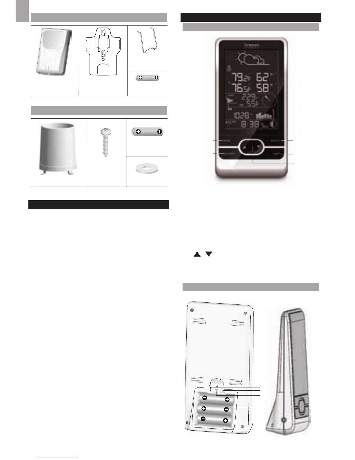
2
FR
SONDE DE TEMPÉRATURE & D’HUMIDITÉ
PLUVIOMÈTRE
ACCESSOIRES - CAPTEURS
Cet appareil peut fonctionner avec jusqu’à 3 capteurs
à tout moment pour détecter la température extérieure,
l’humidité relative ou les rayons UV en divers lieux.
Des capteurs à distance sans fil comme ceux-ci-
dessous peuvent être achetés séparément. Pour plus
d’information, contacter le détaillant le plus proche.*
• Panneau solaire STC800 connectable à l’anémomètre
et au thermo hygromètre
• Thermo-hygro THGR810 (10-Canaux)
• Sonde UV UVN800
• Sonde de piscine THWR800
*Caractéristiques et accessoires ne seront pas valables
pour tous les pays.
VUE D’ENSEMBLE
FACE AVANT
31
2
4
5
1. MODE: permet d'alterner entre les différents modes
d'afchages / réglages ; de régler l'horloge, l'altitude
et d’activer l’auto balayage
2. MAX/MIN: afche les relevés de mémoire maxi et
mini / efface les relevés
3. SELECT: permet de sélectionner entre les différentes
zones
4. LIGHT: permet d'activer le rétro-éclairage
5. / : augmente / diminue les valeurs du réglage
sélectionné ; permet d’alterner entre les canaux
intérieurs et extérieurs
FACE ARRIÈRE
1
2
4
3
5
6
2 piles UM-4
AAA 1,5V
1 support de
xation murale
1 sonde de
température /
humidité
2 piles UM-
3 / AA
4 vis
(Type B)
1 collecteur de pluie
6 rondelles
1 x installation
sur pied
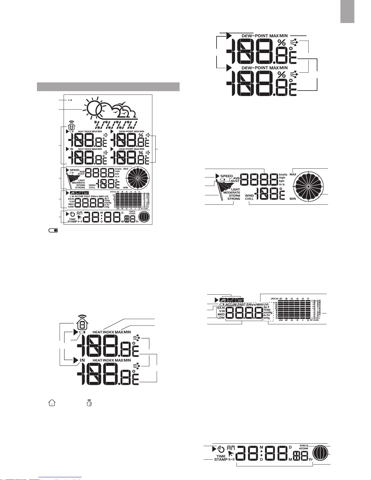
3
FR
1. RESET: réinitialise l’appareil aux réglages par défaut
2. UNIT: permet de sélectionner l’unité de mesure
3. SEARCH: initie une recherche des capteurs ou du
signal radio piloté
4. EU / UK: sélectionne le signal radio le plus proche
(modèle WMR86NS uniquement)
5. Compartiment des piles
6. Prise adaptateur AC
AFFICHAGE LCD
1
2
A
B
C
D
E
1. : les piles de l’apareil principal sont faibles
2. Prévision météorologique
A. Zone température / indice de chaleur
B. Zone humidité / point de rosée
C. Zone vitesse du vent / direction du vent / sensation de
froid dûe au vent (windchill) (refroidissement éolien)
D. Zone indice UVI / baromètre / precipitation
E. Zone horloge / calendrier / cycle lunaire
A Zone température / indice de chaleur
1
3
2
5
6
7
4
1. La température et l’humidité des canaux intérieurs
/ extérieurs sont afchées
2. La pile de la sonde extérieure est faible
3. Icône de zone sélectionnée
4. Indique que les températures MAX / MIN sont afchées
5. Changement de température
6. Relevés de la température (°C / °F)
7. Indice de chaleur
B Zone humidité / point de rosée
1
2
5
3
4
1. Niveau de point de rosée – Température afché
2. Niveau d’humidité / du point de rosée MAX / MIN afchés
3. Variation d’humidité
4. Relevés d’humidité
5. Icône de zone sélectionnée
C Zone vitesse du vent / direction du vent / sensation
de froid dûe au vent (windchill)
3
1
2
5
6
4
8
7
1. MAX Afchage en mémoire de la vitesse du vent
2. Relevé de la vitesse du vent (m/s, knots, kph or mph)
3. Indicateur de piles faibles du capteur de vent
4. Indicateur de la vitesse du vent (AVG/GUST)
5. Indicateur de niveau de la vitesse du vent
6. Description du niveau de la vitesse du vent
7. Afchage de l’effet éolien minimum
8. Indicateur de direction du vent
D Zone indice UVI / baromètre / précipitation
1
2
3
5
4
7
8
6
1. Baromètre/UVI/Indicateur de relevé des précipitations
2. Indice UVI en extérieure/Indicateur de piles faibles
du pluviomètre
3. ACCUM/PAST 24hrs – afchage les précipitations
cumulées des dernières 24 heures.
4. Baromètre/UVI/Relevé des précipitations.
5. Indicateur du niveau d’UVI
6. Pression barométrique/UVI/Afchage de l’unité des
précipitations.
7. MAX Afchage baromètre/UVI/Précipitation
8. Pression barométrique/UVI/Afchage du diagramme
de l’historique des précipitations.
E Zone horloge / calendrier / cycle lunaire
1
2
3
4
5
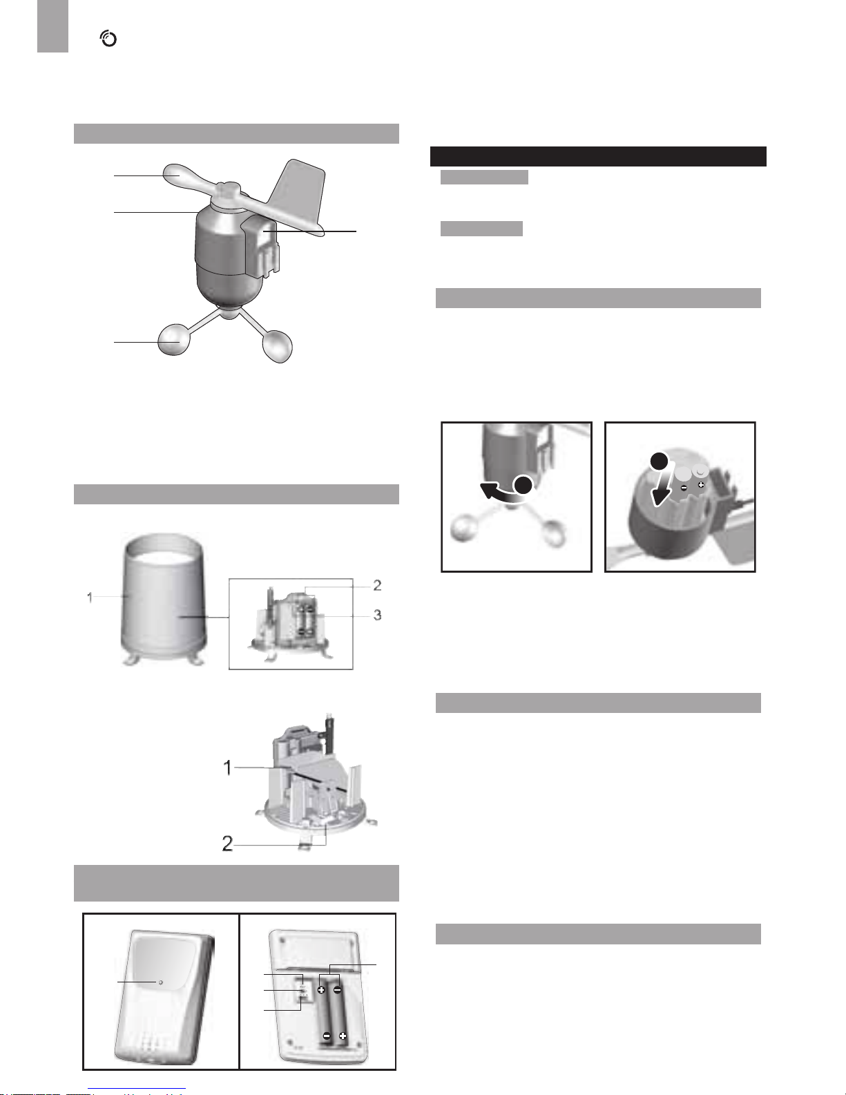
4
FR
1. : indicateur de réception du signal de l’horloge
2. Afchage de l’heure d’un relevé
3. Fuseau horaire
4. Cycle lunaire
5. Heure / date / calendrier
ANÉMOMÈTRE-GIROUETTE
1
2
3
4
1. Direction du vent
2. Boîtier de la girouette
3. Anémomètre
4. Prise de connexion au panneau solaire
PLUVIOMÈTRE
Base et entonnoir:
1. Pluviomètre
2. Compartiment à piles
3. Bouton RESET
1. Entonnoir
2. Indicateur
SONDE DE TEMPÉRATURE & D’HUMIDITÉ
EXTÉRIEURE
1
5
2
3
4
CF
1. Indicateur LED
2. Fente RESET (Réinitialiser)
3. C° / °F: Permet de sélectionner l’unité de mesure de
la température
4. Bouton CHANNEL
5. Compartiment des piles
DÉMARRAGE
REMARQUE Installez les piles dans les sondes à
distance avant d’installer celles de la station de base,
veillez à respecter les polarités (+/-).
REMARQUE
Utiliser des piles alcalines pour une plus
grande longévité et des piles au lithium en vente aux
particuliers pour des températures en dessous de 0 c.
INSTALLATION DE L’ANÉMOMÈTRE
Le capteur de vent fait des lectures de la vitesse et la
direction du vent.
Le capteur est alimenté par des piles. Il transmet des
données à la station de base à une distance de 100
mètres (328 pieds).
Installation des piles :
1
2
1. Dévisser l’anémomètre du capteur de vent
soigneusement.
2. Installer les piles en veillant à la polarité correcte (+/-)
et replacer l’anémomètre. Appuyer sur RESET après
chaque changement de piles.
INSTALLATION DU THERMO HYGROMÈTRE
La sonde sans l est à même de collecter les données
sur 3 canaux.
Installation de la sonde sans l:
1. Ouvrez le couvercle du compartiment des piles.
2. Positionnez l’interrupteur de canal pour sélectionner
un canal (1, 2, 3). Assurez-vous d’utiliser un canal
différent pour chaque sonde.
3. Insérez les piles, en respectant les polarités (+/-).
4. Appuyer sur RESET après chaque changement de
piles.
5. Fermez le couvercle du compartiment des piles.
RÉGLAGE DU PLUVIOMÈTRE
La pluviomètre collecte les précipitations et indique les
relevés. Le capteur transmet les données à la station
de base.
 Loading...