

Page 1

Operating Manual
OPTIMOD-FM
8600
Digital Audio Processor
Version 4.1 Software
Page 2
IMPORTANT NOTE: Refer to the unit’s rear panel for your Model Number.
Model Number:
Description:
8600
OPTIMOD 8600, Stereo Encoder, Digital I/O, Protec-
8600FM
As above, except HD Radio™ / Digital Radio /
h
I
h
I
8600J
8600X
8600XJ
8600FMJ
RISK OF ELECTRIC SHOCK
DO NOT OPEN
tion Structure, Two-Band Structure, Multi-Band
Structure, HD Radio™ / Digital Radio / Netcast Processing,115V (for 100-130V operation) or 230V (for
200-250V operation), switchable to 50µs or 75µs.
8600J and 8600FMJ are for 90-117V operation.
8600X has a blank front panel and must be controlled via 8600 PC Remote software.
Netcast Processing omitted. Upgradeable to 8600.
8600FMJ for 90-117V operation
CAUTION
CAUTION:
NO USER SERVICEABLE PARTS INSIDE. REFER SERVICING TO QUALIFIED SERVICE PERSONNEL.
WARNING: TO REDUCE THE RISK OF FIRE OR ELECTRICAL SHOCK,
DO NOT EXPOSE THIS APPLIANCE TO RAIN OR MOISTURE.
This symbol, wherever it appears, alerts you to
the presence of uninsulated dangerous voltage
inside the enclosure voltage that may be
sufficient to constitute a risk of shock.
TO REDUCE THE RISK OF ELECTRICAL SHOCK, DO NOT REMOVE COVER (OR BACK).
In accordance to the WEEE (waste electrical and electronic equipment) directive of the European Parliam ent, this product must not be discarded into
the municipal waste stream in any of the Member S tates. This product ma y be
sent back to your Orban dealer at end of li fe where it will be reused or recycled at no cost to you.
If this product is discarded into an appr oved muni cipa l WEEE collecti on sit e or
turned over to an approved W EEE recycler at end of life, your Orban d ealer
must be notified and supplied with model, s erial number and the name and
location of site/facility.
Please contact your Orban dealer for further assistance.
www.orban.com
This symbol, wherever it appears, alerts you to important
operating and maintenance instructions in the accompanying literature. Read the manual.
Page 3

IMPORTANT SAFETY INSTRUCTIONS
All the safety and operating instructions should be read before the appliance is operated.
h
Conductor
WIRE COLOR
Normal
Alt
L
LIVE
BROWN
BLACK
N
NEUTRAL
BLUE
WHITE
E
EARTH GND
GREEN-YELLOW
GREEN
Retain Instructions: The safety and operation instructions should be retained for future reference.
Heed Warnings: All warnings on the appliance and in the operating instructions should be adhered to.
Follow Instructions: All operation and user instructions should be followed.
Water and Moisture: The appliance should not be used near water (e.g., near a bat htub, washbowl, kitchen sink, laundry tub, in a wet base-
ment, or near a swimming pool, etc.).
Ventilation: The appliance should be situated so that its location or position does not interfere with its proper ventilation. For example, the appli-
ance should not be situated on a bed, sofa, rug, or similar surface that may block the ventilation openings; or, placed in a built-in installation, such as a
bookcase or cabinet that may impede the flow of air through the ventilation openings.
Heat: The appliance should be situated away from heat sourc es such as radiators, heat registers, stoves, or other applianc es (including amplifiers)
that produce heat.
Power Sources: The appliance should be connected to a power supply only of the type described i n the operating instructions or as marked on
the appliance.
Grounding or Polarization: Precautions should be taken so that the grounding or polarization means of an appliance is not defeated.
Power-Cord Protection: Power-supply cords should be routed so that they are not likely to be walk ed on or pinched by items placed upon or
against them, paying particular attention to cords at plugs, convenience receptacles, and the point where they exit from the appliance.
Cleaning: The appliance should be cleaned only as recommended by the manufacturer.
Non-Use Periods: The power cord of the appliance should be unplugged from the outlet when left unused for a long period of time.
Object and Liquid Entry: Care should be taken so that objects do not fall and liquids are not spilled into the enclosure through openings.
Damage Requiring Service: The appliance should be serviced by qualified service pers onnel when: The power supply cord or the plug has
been damaged; or Objects have fallen, or liquid has been spi lled into the appliance; or The appliance has been exposed to rai n; or The appliance
does not appear to operate normally or exhibits a marked change in performance; or The appliance has been dropped, or the enclosure damaged.
Servicing: The user should not attempt to s ervice the appliance beyond that described in the operating instructions. All other servici ng should be
referred to qualified service personnel.
The Appliance should be used only with a cart or stand that is recommended by the manufacturer.
Safety Instructions (European)
Notice For U.K. Customers If Your Unit Is Equipped With A Power Cord.
WARNING: THIS APPLIANCE MUST BE EARTHED.
The cores in the mains lead are coloured in accordance with the following code:
GREEN and YELLOW - Earth BLUE - Neutral BROWN - Live
As colours of the cores in the mains lead of this appliance may not correspond with the coloured markings identifying the terminals in your plug, pro-
ceed as follows:
The core which is coloured green and yellow must be connected to the terminal in the plug marked with the l etter E, or with the earth symbol, or col-
oured green, or green and yellow.
The core which is coloured blue must be connected to the terminal marked N or coloured black.
The core which is coloured brown must be connected to the terminal marked L or coloured red.
The power cord is terminated in a CEE7/7 plug (Continental Europe). The green/yellow wire is connected directly to the unit's chassis. If you need to
change the plug and if you are qualified to do so, refer to the table below.
WARNING: If the ground is defeated, certain fault conditions in the unit or in the system to which i t is c onnected can result i n full line voltage bet ween
chassis and earth ground. Severe injury or death can then result if the chassis and earth ground are touched simultaneously.
AC Power Cord Color Coding
Page 4

Safety Instructions (German)
Gerät nur an der am Leistungsschild vermerkten Spannung und Stromart betreiben.
Sicherungen nur durch solche, gleicher Stromstärke und gleichen Abschaltverhaltens ersetzen. Sicherungen nie überbrücken.
Jedwede Beschädigung des Netzkabels vermeiden. Netzkabel nicht knicken oder quetschen. Beim Abziehen des Netzkabels den
Stecker und nicht das Kabel enfassen. Beschädigte Netzkabel sofort auswechseln.
Gerät und Netzkabel keinen übertriebenen mechanischen Beaspruchungen aussetzen.
Um Berührung gefährlicher elektrischer Spannungen zu vermeiden, darf das Gerät nicht geöffnet werden. Im Fall von Betriebsstörungen darf das Gerät nur Von befugten Servicestellen instandgesetzt werden. Im Gerät befinden sich keine, durch den Benutzer
reparierbare Teile.
Zur Vermeidung von elektrischen Schlägen und Feuer ist das Gerät vor Nässe zu schützen. Eindringen von Feuchtigkeit und
Flüssigkeiten in das Gerät vermeiden.
Bei Betriebsstörungen bzw. nach Eindringen von Flüssigkeiten oder anderen Gegenständen, das Gerät sofort vom Netz trennen und
eine qualifizierte Servicestelle kontaktieren.
Safety Instructions (French)
On s'assurera toujours que la tension et la nature du courant utilisé correspondent bien à ceux indiqués sur la plaque de l'appareil.
N'utiliser que des fusibles de même intensité et du même principe de mise hors circuit que les fusibles d'origine. Ne jamais
shunter les fusibles.
Eviter tout ce qui risque d'endommager le câble seceur. On ne devra ni le plier, ni l'aplatir. Lorsqu'on débranche l'appareil,
tirer la fiche et non le câble. Si un câble est endommagé, le remplacer immédiatement.
Ne jamais exposer l'appareil ou le câble ä une contrainte mécanique excessive.
Pour éviter tout contact averc une tension électrique dangereuse, on n'oouvrira jamais l'appareil. En cas de dysfonctionnement,
l'appareil ne peut être réparé que dans un atelier autorisé. Aucun élément de cet appareil ne peut être réparé par l'utilisateur.
Pour éviter les risques de décharge électrique et d'incendie, protéger l'appareil de l'humidité. Eviter toute pénétration
d'humidité ou fr liquide dans l'appareil.
En cas de dysfonctionnement ou si un liquide ou tout autre objet a pénétré dans l'appareil couper aussitôt l'appareil
de son alimentation et s'adresser à un point de service aprésvente autorisé.
Safety Instructions (Spanish)
Hacer funcionar el aparato sólo con la tensión y clase de corriente señaladas en la placa indicadora de características.
Reemplazar los fusibles sólo por otros de la misma intensidad de corriente y sistema de desconexión. No poner nunca los fusibles en
puente.
Proteger el cable de alimentación contra toda clase de daños. No doblar o apretar el cable. Al desenchufar, asir el enchufe y no el
cable. Sustituir inmediatamente cables dañados.
No someter el aparato y el cable de alimentación a esfuerzo mecánico excesivo.
Para evitar el contacto con tensiones eléctricas peligrosas, el aparato no debe abrirse. En caso de producirse fallos de funcionamiento,
debe ser reparado sólo por talleres de servicio autorizados. En el aparato no se encuentra ninguna pieza que pudiera ser reparada por
el usuario.
Para evitar descargas eléctricas e incendios, el aparato debe protegerse contra la humedad, impidiendo que penetren ésta o líquidos
en el mismo.
En caso de producirse fallas de funcionamiento como consecuencia de la penetración de líquidos u otros objetos en el aparato,
hay que desconectarlo inmediatamente de la red y ponerse en contacto con un taller de servicio autorizado.
Safety Instructions (Italian)
Far funzionare l'apparecchio solo con la tensione e il tipo di corrente indicati sulla targa riportante i dati sulle prestazioni.
Sostituire i dispositivi di protezione (valvole, fusibili ecc.) solo con dispositivi aventi lo stesso amperaggio e lo stesso comportamento
di interruzione. Non cavallottare mai i dispositivi di protezione.
Evitare qualsiasi danno al cavo di collegamento alla rete. Non piegare o schiacciare il cavo. Per staccare il cavo, tirare la presa e mai
il cavo. Sostituire subito i cavi danneggiati.
Non esporre l'apparecchio e il cavo ad esagerate sollecitazioni meccaniche.
Per evitare il contatto con le tensioni elettriche pericolose, l'apparecchio non deve venir aperto. In caso di anomalie di funzionamento
l'apparecchio deve venir riparato solo da centri di servizio autorizzati. Nell'apparecchio non si trovano parti che possano essere riparate
dall'utente.
Per evitare scosse elettriche o incendi, l'apparecchio va protetto dall'umidità. Evitare che umidità o liquidi entrino nell'apparecchio.
In caso di anomalie di funzionamento rispettivamente dopo la penetrazione di liquidi o oggetti nell'apparecchio, staccare immediatamente
l'apparecchio dalla rete e contattare un centro di servizio qualificato.
Page 5

PLEASE READ BEFORE PROCEEDING!
Manual
The Operating Manual contains instructions to verify the proper operation of this unit and initialization of certain options.
You will find these operations are most conveniently performed on the bench before you install the unit in the rack.
Please review the Manual, especially the installation section, before unpacking the unit.
Trial Period Precaut i ons
If your unit has been provided on a trial basis:
You should observe the following precautions to avoid reconditioning charges in case you later wish to return the unit to
your dealer.
(1) Note the packing technique and save all packing materials. It is not wise to ship in other than the factory carton. (Re-
placements cost $35.00).
(2) Avoid scratching the paint or plating. Set the unit on soft, clean surfaces.
(3) Do not cut the grounding pin from the line cord.
(4) Use care and proper tools in removing and tightening screws to avoid burring the heads.
(5) Use the nylon-washered rack screws supplied, if possible, to avoid damaging the panel. Support the unit when tighten-
ing the screws so that the threads do not scrape the paint inside the slotted holes.
Packing
When you pack the unit for shipping:
(1) Tighten all screws on any barrier strip(s) so the screws do not fall out from vibration.
(2) Wrap the unit in its original plastic bag to avoid abrading the paint.
(3) Seal the inner and outer cartons with tape.
If you are returning the unit permanently (for credit), be sure to enclose:
• The Manual(s)
• The Registration / Warranty Card
• The Line Cord
• All Miscellaneous Hardware (including the Rack Screws and Keys)
• The Extender Card (if applicable)
• The Monitor Rolloff Filter(s) (OPTIMOD-AM only)
• The COAX Connecting Cable (OPTIMOD-FM and OPTIMOD-TV only)
Your dealer may charge you for any missing items.
If you are returning a unit for repair, do not enclose any of the above items.
Further advice on proper packing and shipping is included in the Manual (see Table of Contents).
Trouble
If you have problems with installation or operation:
(1) Check everything you have done so far against the instructions in the Manual. The information contained therein is
based on our years of experience with OPTIMOD and broadcast stations.
(2) Check the other sections of the Manual (consult the Table of Contents and Index) to see if there might be some sug-
gestions regarding your problem.
(3) After reading the section on Factory Assistance, you may call Orban Customer Service for advice during normal Cali-
fornia business hours. The number is +1 856.719.9900.
Page 6

I
WARNING
This equipment generates, uses, and can radiate radio-frequency energy. If it is not installed
and used as directed by this manual, it may cause interference to radio communicati on. This
equipment complies with the limits for a Class A computing device, as specified by FCC
Rules, Part 15, subject J, which are designed to provide reasonable protection against such
interference when this type of equipment is operated in a commercial envi ronment. Operation
of this equipment in a residential area is likely to cause interference. If it does, the user will be
required to eliminate the interference at the user’s expense.
I
I
WARNING
This digital apparatus does not exceed the Class A limits for radio noise emis sions from digital apparatus set out in the radio Interference Regulations of the Canadian Department of
Communications. (Le present appareil numerique n’emet pas de bruits radioel ectriques depassant les limites applicables aux appareils numeriques [de las class A] prescrites dans le
Reglement sur le brouillage radioelectrique edicte par le ministere des Comm unications du
Canada.)
IMPORTANT
Perform the installation under static control conditions. Simply walking across a rug can generate a static charge of 20,000 volts. This is the spark or shock you may have felt when
touching a doorknob or some other conductive surface. A much smaller static discharge is
likely to destroy one or more of the CMOS semiconductors employed in OPTIMOD-FM. Static
damage will not be covered under warranty.
There are many common sources of static. Most involve some type of friction between two
dissimilar materials. Some examples are combing your hair, sliding across a seat cover or
rolling a cart across the floor. Since the threshold of human perception for a static discharge
is 3000 volts, you will not even notice many damaging discharges.
Basic damage prevention consists of minimizing generation, discharging any accumulated
static charge on your body or workstation, and preventing that discharge from being sent to or
through an electronic component. You should use a static grounding strap (grounded through
a protective resistor) and a static safe workbench with a conductive surface. This will prevent
any buildup of damaging static.
All firmware and software © Orban.
Orban and Optimod are registered trademarks.
All trademarks are property of their respective companies.
This manual was published September 2016.
© Copyright Orban. This document may be freely printed and distributed by Orban’s customers, but its text may not be
incorporated into derivative works.
Orban Labs Inc., 7209 Browning Road, Pennsa uken NJ 08110 USA
Phone: +1 856.719.9900; E-Mail: [email protected]; Site: www.orban.com
Page 7

Operating Manual
OPTIMOD-FM
8600
Digital Audio Processor
Version 4.1 Software
Page 8

Table of Contents
Index ....................................................................................................................... 0-11
Section 1 Introduction
......................................................................................................................................... 1-1
ABOUT THIS MANUAL ....................................................................................................... 1-1
THE OPTIMOD-FM 8600 DIGITAL AUDIO PROCESSOR ....................................................... 1-1
User-Friendly Interface ............................................................................................ 1-2
Absolute Control of Peak Modulation ................................................................... 1-2
Flexible Configuration ............................................................................................ 1-4
Adaptability through Multiple Audio Processing Structures ............................... 1-5
Controllable ............................................................................................................. 1-6
8600MPX Features ................................................................................................... 1-8
PRESETS IN OPTIMOD-FM............................................................................................... 1-8
Factory Presets ......................................................................................................... 1-8
User Presets .............................................................................................................. 1-8
INPUT/OUTPUT CONFIGURATION ......................................................................................... 1-9
Digital AES3 Left/right Input/outputs .................................................................... 1-9
Analog Left/right Input/output ............................................................................ 1-10
Stereo Baseband Composite Output .................................................................... 1-10
Digital Composite Outputs ............................................................................................ 1-10
Subcarriers .............................................................................................................. 1-11
Digitized Subcarrier Inputs ............................................................................................ 1-11
Wordclock/10 MHz Sync Reference Input ............................................................ 1-11
Remote Control Interface ..................................................................................... 1-12
Computer Interface ............................................................................................... 1-12
RS-232 Serial Port (Serial 1) ............................................................................................ 1-12
RS-232 Serial Port (Serial 2) ............................................................................................ 1-12
100 Mbps Ethernet Port ................................................................................................. 1-12
LOCATION OF OPTIMOD-FM ......................................................................................... 1-13
Optimal Control of Peak Modulation Levels ....................................................... 1-13
Best Location for OPTIMOD-FM ........................................................................... 1-14
If the transmitter is not accessible: ................................................................................ 1-14
If the transmitter is accessible: ...................................................................................... 1-14
STUDIO-TRANSMITTER LINK ............................................................................................. 1-16
Transmission from Studio to Transmitter ............................................................. 1-16
Digital Links .................................................................................................................... 1-16
Composite Baseband Microwave STLs (Analog and Digital) ........................................ 1-18
Dual Microwave STLs ...................................................................................................... 1-18
Analog Landline (PTT / Post Office Line) ....................................................................... 1-19
Using the Orban 8100AST (or 8100A/ST) External AGC with the 8600 .............. 1-19
STL and Exciter Overshoot .................................................................................... 1-20
USING LOSSY DATA REDUCTION IN THE STUDIO ................................................................. 1-20
ABOUT TRANSMISSION LEVELS AND METERING .................................................................. 1-21
Meters .................................................................................................................... 1-21
Studio Line-up Levels and Headroom .................................................................. 1-21
Figure 1-2: Absolute Peak Level, VU and PPM Indications ........................................... 1-22
Transmission Levels ................................................................................................ 1-22
LINE-UP FACILITIES ......................................................................................................... 1-23
Metering of Levels and Subjective Loudness ....................................................... 1-23
Page 9

Figure 1-3: VU Meter Indication Compared to Peak Level vs. Time ............................. 1-23
Left/right Output Level ................................................................................................... 1-23
Composite Output Level ................................................................................................. 1-24
BS.1770 Loudness Level .................................................................................................. 1-24
Figure 1-4: BS.1770 Loudness Meter Block Diagram (from ITU-R document) .............. 1-24
Built-in Calibrated Line-up Tones .................................................................................. 1-25
Built-in Calibrated Bypass Test Mode ............................................................................ 1-26
MONITORING ON LOUDSPEAKERS AND HEADPHONES ......................................................... 1-26
Low-Delay Monitoring .................................................................................................... 1-28
EAS TEST ...................................................................................................................... 1-29
PC CONTROL AND SECURITY PASSCODE ............................................................................ 1-30
WARRANTY, USER FEEDBACK .......................................................................................... 1-30
User Feedback ........................................................................................................ 1-30
LIMITED WARRANTY ............................................................................................. 1-30
INTERNATIONAL WARRANTY ............................................................................... 1-31
Section 2 Installation
......................................................................................................................................... 2-1
INSTALLING THE 8600 ....................................................................................................... 2-1
Figure 2-1: AC Line Cord Wire Standard) ......................................................................... 2-2
Figure 2-2: Wiring the 25-pin Remote Interface Connector ........................................... 2-4
8600 REAR PANEL ........................................................................................................... 2-5
AUDIO INPUT AND OUTPUT CONNECTIONS .......................................................................... 2-6
Cable ......................................................................................................................... 2-6
Connectors ............................................................................................................... 2-6
Analog Audio Input ................................................................................................. 2-6
Analog Audio Output ............................................................................................. 2-7
AES3 Digital Input and Output ............................................................................... 2-7
Connecting a Ratings Encoder ................................................................................ 2-8
COMPOSITE OUTPUT AND SUBCARRIER INPUTS ..................................................................... 2-9
Figure 2-3: Separation vs. load capacitance .................................................................. 2-10
Digital Composite Outputs ............................................................................................. 2-11
Digitized Subcarrier Inputs ............................................................................................. 2-11
Wordclock/10 MHz Sync Reference Input ...................................................................... 2-11
GROUNDING .................................................................................................................. 2-12
Power Ground ........................................................................................................ 2-12
Circuit Ground ....................................................................................................... 2-12
8600 FRONT PANEL ....................................................................................................... 2-13
EXTERNAL AGC INSTALLATION (OPTIONAL) ....................................................................... 2-15
If you are using an Orban 8200ST external AGC: ................................................ 2-16
Figure 2-4: 8200ST Jumper Settings (*Factory Configuration) ..................................... 2-16
QUICK SETUP ................................................................................................................. 2-18
ANALOG AND DIGITAL I/O SETUP ..................................................................................... 2-27
USING CLOCK-BASED AUTOMATION ................................................................................. 2-42
SECURITY AND PASSCODE PROGRAMMING ......................................................................... 2-44
To Unlock the Front Panel ..................................................................................... 2-46
8600 User Interface Behavior during Lockout ............................................................... 2-46
Default ADMIN Passcode ................................................................................................ 2-47
Security and Orban’s PC Remote Application ...................................................... 2-47
Passcodes and Software Updates ......................................................................... 2-48
If you have forgotten your “All Screens” passcode… ........................................ 2-48
ADMINISTERING THE 8600 THROUGH ITS SERIAL PORTS OR ETHERNET .................................. 2-48
Page 10

Connecting via Serial Port #2 Using a Terminal Program on a PC ..................... 2-49
Administrative Operations Available via Serial Port #2 ............................................... 2-50
Connecting to the 8600’s Ethernet Port or Serial Port #1 via a Terminal Program
on a PC ................................................................................................................... 2-57
Direct Control Using PuTTY ........................................................................................... 2-58
Automated Control Using PuTTY/Plink ......................................................................... 2-59
Automated Control Using Netcat .................................................................................. 2-60
REMOTE CONTROL INTERFACE PROGRAMMING .................................................................. 2-60
TALLY OUTPUT PROGRAMMING ....................................................................................... 2-62
NETWORKING AND REMOTE CONTROL .............................................................................. 2-63
INSTALLING 8600 PC REMOTE CONTROL SOFTWARE .......................................................... 2-66
Installing the Necessary Windows Services .......................................................... 2-66
Check Hardware Requirements ............................................................................ 2-67
Running the Orban Installer Program ................................................................. 2-67
Setting Up Ethernet, LAN, and VPN Connections ............................................... 2-68
Conclusion .............................................................................................................. 2-69
SYNCHRONIZING OPTIMOD TO A NETWORK TIME SERVER ................................................... 2-69
Updating your 8600’s Software ............................................................................ 2-72
APPENDIX: SETTING UP SERIAL COMMUNICATIONS ............................................................. 2-75
Preparing for Communication through a Null Modem Cable ........................... 2-75
Connecting Using Windows 2000 Direct Serial Connection: .............................. 2-75
Connecting Using Windows XP Direct Serial Connection................................... 2-81
Connecting Using Windows 7 Direct Serial Connection: .................................... 2-85
Preparing for Communication through Modems ............................................... 2-95
Connecting Using Windows 2000 Modem Connection ...................................... 2-95
Connecting using Windows XP Modem Connection ........................................ 2-100
SNMP SUPPORT .......................................................................................................... 2-106
SNMP Network Setup ................................................................................................... 2-106
SNMP Mib file ............................................................................................................... 2-107
SNMP Default Settings ................................................................................................. 2-107
SNMP Features .............................................................................................................. 2-107
RDS/RBDS GENERATOR ............................................................................................... 2-110
Using System I/O ........................................................................................................... 2-110
Table 2-1: System I/O RDS controls and defaults ........................................................ 2-111
Using Processing Presets .............................................................................................. 2-112
Using the Terminal Server ............................................................................................ 2-113
Using Telnet to Control the Terminal Server .............................................................. 2-113
Security ......................................................................................................................... 2-115
RDS Terminal Commands ............................................................................................. 2-115
Table 2-2: Preset/Terminal RDS controls and defaults ................................................ 2-117
Alternative Frequency Channel Numbers ................................................................... 2-118
Table 2-3: Alternative Frequency Channel Numbers: ................................................. 2-119
Program Type (PTY)...................................................................................................... 2-119
Table 2-4: Program Type (PTY) .................................................................................... 2-119
SCA/Subcarrier Phase Relationship .............................................................................. 2-119
Figure 2-5: Pilot/SCA Phasing Scope Trace .................................................................. 2-120
References .................................................................................................................... 2-120
Section 3 Operation
......................................................................................................................................... 3-1
8600 FRONT PANEL ......................................................................................................... 3-1
Page 11

INTRODUCTION TO PROCESSING .......................................................................................... 3-3
Some Audio Processing Concepts ........................................................................... 3-3
Distortion in Processing........................................................................................... 3-4
Loudness and Distortion ......................................................................................... 3-4
OPTIMOD-FM—from Bach to Rock ........................................................................ 3-5
Fundamental Requirements: High-Quality Source Material and Accurate
Monitoring ............................................................................................................... 3-6
ABOUT THE 8600’S SIGNAL PROCESSING FEATURES .............................................................. 3-7
Dual-Mono Architecture ......................................................................................... 3-7
Signal Flow ............................................................................................................... 3-7
“Multipath Mitigator” Left/Right Phase Skew Correction ............................................. 3-8
ITU-R 412 Compliance for Analog FM Broadcasts ............................................... 3-13
Two-Band Purist Processing .................................................................................. 3-14
Digital Radio Processing ........................................................................................ 3-14
BS.1770 Compliance for Digital Radio ................................................................. 3-15
Input/Output Delay ............................................................................................... 3-15
CUSTOMIZING THE 8600’S SOUND ................................................................................... 3-16
Basic Modify ........................................................................................................... 3-16
Intermediate Modify ............................................................................................. 3-17
Advanced Modify .................................................................................................. 3-17
Gain Reduction Metering...................................................................................... 3-18
To Create or Save a User Preset ............................................................................ 3-18
To Delete a User Preset ......................................................................................... 3-19
ABOUT THE PROCESSING STRUCTURES ............................................................................... 3-19
FACTORY PROGRAMMING PRESETS ................................................................................... 3-21
Table 3-1: Factory Programming Presets ....................................................................... 3-22
EQUALIZER CONTROLS .................................................................................................... 3-30
Table 3-2: Equalization Controlsct ................................................................................. 3-31
Table 3-3: Stereo Enhancer Controls .............................................................................. 3-35
STEREO ENHANCER CONTROLS ......................................................................................... 3-35
AGC CONTROLS ............................................................................................................ 3-36
Table 3-4: AGC Controlsa ................................................................................................ 3-37
Advanced AGC Controls ........................................................................................ 3-39
PEAK LIMITER CONTROLS ................................................................................................ 3-42
Table 3-5: Peak Limiter Controls Common to 8500-Style and MX Presets ................... 3-42
Peak Limiter Controls Common to 8500-style and MX Presets .......................... 3-42
Figure 3-1: 0-100 kHz Baseband Spectrum (Loud-Hot preset) ...................................... 3-43
Figure 3-2: 19 kHz Pilot Notch Filter Spectrum (Loud-Hot preset; detail) .................... 3-43
Table 3-6: 8500-Style Peak Limiter Controls .................................................................. 3-46
8500-Style Peak Limiter Controls .......................................................................... 3-47
Figure 3-3: Bass Clipper Input/Output Transfer Curves as Bass Clip Shape Control is
Varied from 0.0 (Hard) to 10.0 (Soft) ............................................................................. 3-48
Advanced 8500-Style Peak Limiter Controls ........................................................ 3-49
8600 MX Technology Peak Limiter Controls ........................................................ 3-49
Table 3-7: MX Technology Peak Limiter Controls ......................................................... 3-50
THE TWO-BAND STRUCTURE ........................................................................................... 3-52
Setting Up the Two-Band Structure for Classical Music ...................................... 3-52
Customizing the Settings ...................................................................................... 3-53
The Two-Band Structure’s Full Setup Controls ..................................................... 3-54
Table 3-8: Two-Band Controls ........................................................................................ 3-54
Advanced Two-Band Controls ............................................................................... 3-57
THE FIVE-BAND STRUCTURE ............................................................................................ 3-58
Putting the Five-Band Structure on the Air ......................................................... 3-59
Page 12

Customizing the Settings ...................................................................................... 3-59
The Five-Band Structure’s Full Setup Controls ..................................................... 3-59
Table 3-9: Multiband Controls ....................................................................................... 3-60
Table 3-10: MB Attack / Release Controls ..................................................................... 3-63
Advanced Multiband and Band Mix Controls ..................................................... 3-66
Table 3-11: MB Band Mix Controls ................................................................................ 3-67
To Override the Speech/Music Detector ........................................................................ 3-70
ABOUT THE 8600’S HD / DIGITAL RADIO PROCESSING ........................................................ 3-71
Delay Difference between HD and FM Outputs ................................................. 3-73
HD I/O Setup Controls ........................................................................................... 3-74
Input/Output > HD Digital Radio screen: ...................................................................... 3-74
Table 3-12: HD I/O Setup Controls ................................................................................. 3-74
Digital Output ................................................................................................................ 3-76
Unique HD Audio Controls ................................................................................... 3-78
Table 3-13: Unique HD Audio Controls (found in HD Limiting page) ......................... 3-78
ITU-R MULTIPLEX POWER CONTROLLER ........................................................................... 3-80
Figure 3-4: Multiplex power over 15 minute observation interval with Multiplex power
controller active, measured at the Optimod’s composite output ............................... 3-81
MPX Power Meter .......................................................................................................... 3-81
Audio Processing and the Multiplex Power Threshold Control ................................... 3-83
About the Multiplex Power Controller’s Time Constants ............................................ 3-83
Table 3-14: Test Modes .................................................................................................. 3-84
TEST MODES ................................................................................................................. 3-84
GETTING THE BASS SOUND YOU WANT ............................................................................ 3-85
Bass Punch in the MX Presets ........................................................................................ 3-86
Summary ......................................................................................................................... 3-87
USING THE 8600 PC REMOTE CONTROL SOFTWARE ........................................................... 3-87
To set up a new connection: ................................................................................. 3-88
To initiate communication: ................................................................................... 3-88
To modify a control setting: ................................................................................. 3-89
To recall a preset: ................................................................................................... 3-89
To save a user preset you have created: .............................................................. 3-90
To back up User Presets, system files, and automation files onto your computer’s
hard drive: .............................................................................................................. 3-90
Note to Users Familiar with Older Version of PC Remote ............................................ 3-91
To restore archived presets, system files, and automation files: ........................ 3-92
To share an archived User Preset between 8600s: ........................................................ 3-93
To modify INPUT/OUTPUT and SYSTEM SETUP: ........................................................... 3-93
To modify AUTOMATION: ......................................................................................... 3-93
To group multiple 8600s: ...................................................................................... 3-94
Operation Using the Keyboard ............................................................................ 3-94
To Quit the Program .............................................................................................. 3-94
About Aliases created by Optimod 8600 PC Remote Software ......................... 3-94
Multiple Installations of Optimod 8600 PC Remote ........................................... 3-95
White Paper: Measuring the Improvements in Optimod-FM 8600’s FM Peak
Limiting Technology .............................................................................................. 3-97
Figure 3-5 Madonna, “Get Together” remix; third-octave difference ....................... 3-97
Introduction .................................................................................................................... 3-97
Figure 3-6 U2, “Within You Without You” ................................................................... 3-98
Measurements ................................................................................................................ 3-98
Figure 3-7 Kelly Clarkson, “Because of You” opening ................................................ 3-99
Figure 3-8 Level 42, “Starchild” .................................................................................. 3-100
Page 13

Figure 3-9 Simple Minds, “Alive and Kicking” ........................................................... 3-101
Figure 3-10 Stanford Research Systems Model SR785 Dynamic Signal Analyzer ...... 3-102
Conclusions .................................................................................................................... 3-102
Section 4 Maintenance
......................................................................................................................................... 4-1
ROUTINE MAINTENANCE ................................................................................................... 4-1
SUBASSEMBLY REMOVAL AND REINSTALLATION .................................................................... 4-1
FIELD AUDIT OF PERFORMANCE ......................................................................................... 4-7
Table 4-1: Decoder Chart for Power Supervisor ............................................................ 4-10
Table 4-2: Layout Diagram of J7, with expected voltages on each pin ....................... 4-10
Table 4-3: Typical Power Supply Voltages and AC Ripple ............................................. 4-10
Section 5 Troubleshooting
......................................................................................................................................... 5-1
PROBLEMS AND POTENTIAL SOLUTIONS ............................................................................... 5-1
RFI, Hum, Clicks, or Buzzes ............................................................................................... 5-1
Unexpectedly Quiet On-Air Levels ................................................................................... 5-1
Poor Peak Modulation Control / Low On-Air Loudness .................................................. 5-1
Audible Distortion On-Air ................................................................................................ 5-2
Audible Noise on Air......................................................................................................... 5-3
Whistle on Air, Perhaps Only in Stereo Reception .......................................................... 5-4
Interference from stereo into SCA ................................................................................... 5-4
Figure 5-1: Typical 8700 baseband spectrum with heavy processing, 0-100 kHz. ......... 5-4
Shrill, Harsh Sound ............................................................................................................ 5-5
Dull Sound ......................................................................................................................... 5-5
System Will Not Pass Line-Up Tones at 100% Modulation ............................................. 5-5
System Will Not Pass Emergency Alert System (“EAS” USA Standard) Tones at the
Legally Required Modulation Level ................................................................................. 5-5
System Receiving 8600’s Digital Output Will Not Lock ................................................... 5-6
19 kHz Frequency Out-of-Tolerance ................................................................................ 5-6
L–R (Stereo Difference Channel) Will Not Null With Monophonic Input ...................... 5-6
Talent Complains About Delay in Their Headphones ..................................................... 5-6
HD Output Sounds Too Bright ......................................................................................... 5-6
Harsh Sibilance (“Ess” Sounds) in the HD Channel ......................................................... 5-6
HD and FM Levels Do Not Match When the Receiver Crossfades .................................. 5-6
Digital Radio Loudness Cannot be Set Using the Digital Output 100% Peak Level
Control ............................................................................................................................... 5-7
Loudness Drops Momentarily During HD Radio Analog/Digital Crossfades .................. 5-7
HD Frequency Response is Limited to 15 kHz .................................................................. 5-7
You Cannot Set Any Output to Emit an HD Signal ......................................................... 5-7
The Left and Right Audio Channels are Reversed at the Digital 1 or Digital 2 Outputs
only .................................................................................................................................... 5-7
Loudness is unexpectedly low from the analog FM processing chain ........................... 5-7
Digitized SCA inputs do not appear at the analog composite outputs and vice-versa
(MPX hardware only) ........................................................................................................ 5-8
General Dissatisfaction with Subjective Sound Quality .................................................. 5-8
BS.1770 Safety Limiter produces too much gain reduction ............................................ 5-8
Security Passcode Lost (When Unit is Locked Out) .......................................................... 5-8
Page 14

Connection Issues between the 8600 and a PC, Modem, or Network ................. 5-8
Chassis
interconnections
(not to scale)
Base Board
Glue logic; supports CPU board
Parts Locator
6-38
Troubleshooting Connections ................................................................................. 5-9
You Cannot Access the Internet After Making a Direct or Modem Connection to
the 8600: ................................................................................................................ 5-10
OS-SPECIFIC TROUBLESHOOTING ADVICE .......................................................................... 5-10
Troubleshooting Windows XP Direct Connect: ................................................... 5-10
Troubleshooting Windows XP Modem Connect: ................................................ 5-11
TROUBLESHOOTING IC OPAMPS ....................................................................................... 5-12
TECHNICAL SUPPORT ...................................................................................................... 5-12
FACTORY SERVICE ........................................................................................................... 5-13
SHIPPING INSTRUCTIONS .................................................................................................. 5-13
Section 6 Technical Data
......................................................................................................................................... 6-1
SPECIFICATIONS ................................................................................................................ 6-1
Performance ............................................................................................................. 6-1
Installation ............................................................................................................... 6-2
CIRCUIT DESCRIPTION ....................................................................................................... 6-6
Overview .................................................................................................................. 6-7
Control Circuits ........................................................................................................ 6-7
User Control Interface and LCD Display Circuits ................................................... 6-8
Input Circuits ............................................................................................................ 6-9
Output Circuits ....................................................................................................... 6-10
DSP Circuit .............................................................................................................. 6-12
AES Output L/R Channel Reversal Bug .......................................................................... 6-13
Power Supply ......................................................................................................... 6-14
ABBREVIATIONS ............................................................................................................. 6-14
PARTS LIST .................................................................................................................... 6-16
Obtaining Spare Parts ........................................................................................... 6-16
Base Board ............................................................................................................. 6-17
CPU board .............................................................................................................. 6-18
RS-232 Board .......................................................................................................... 6-20
Power Supply ......................................................................................................... 6-21
Input/Output (I/O) Board ...................................................................................... 6-22
DSP Board ............................................................................................................... 6-26
Interface Board ...................................................................................................... 6-28
Headphone Board ................................................................................................. 6-29
Encoder Board ....................................................................................................... 6-30
LCD Carrier Board .................................................................................................. 6-30
Digital MPX (Retrofit for pre-MPX 8600s) ........................................................... 6-31
Digital MPX (for 8600MPX Units) ......................................................................... 6-32
SCHEMATICS AND PARTS LOCATOR DRAWINGS ................................................................... 6-34
Function Description Drawing Page
Circuit Board Locator and basic
Top view
6-37
Page 15

Function Description Drawing Page
and RS-232 daughterboard.
Contains:
Drawing
System Connections
Schematic 1 of 4
6-39
CPU board interface
Schematic 2 of 4
6-40
Power Supply Monitor
Schematic 3 of 4
6-41
CPLD, General Purpose Interface,
and Remotes
Schematic 4 of 4
6-42
CPU board
Control microprocessor. Services
front panel, serial port, Ethernet,
Contains:
Parts Locator
6-43
Ethernet
Schematic 1 of 5
6-44
General Purpose Bus
Schematic 2 of 5
6-45
Memory
Schematic 3 of 5
6-46
Miscellaneous Functions
Schematic 4 of 5
6-47
Power and Ground Distribution
Schematic 5 of 5
6-48
RS-232 Board
Supports Serial Port
Parts Locator
Drawing
Schematic 1 of 1
6-50
Power Supply
±
±5V analog
supply; +5V digital supply
Drawing
Schematic 1 of 1
6-52
I/O Board
Contains:
L and R Analog Inputs
Schematic 1 of 6
6-54 L and R Analog Outputs
Schematic 2 of 6
6-55 Composite / SCA
Schematic 3 of 6
6-56
Control and Miscellaneous
Schematic 5 of 6
6-58 Interface and Power Distribution
Schematic 6 of 6
6-59
DSP Board
DSP Chips; Local +3.3V regulator.
Contains:
Parts Locator
Drawing
6-60
Interconnects
Schematic 1 of 9
6-61
Enhanced Serial Audio
Interface (ESAI)
Schematic 2 of 9
6-62
Control Interface
Schematic 3 of 9
6-63
External Memory Controller
Interface 1
Schematic 4 of 9
6-64
Power and Ground
Schematic 5 of 9
6-65 86xx 8-Bit Control Interface
Schematic 6 of 9
6-66 Clock Generation and CPLD
Schematic 7 of 9
6-67 Power Distribution
Schematic 8 of 9
6-68
External Memory Controller
Interface 2
Schematic 9 of 9
6-69
Front-Panel
LCD Carrier
Parts Locator
6-70
DSP board, and control board. Resides on base board.
Drawing
6-49
15V analog supply;
Analog Input/output
AES3 Input/output
Composite Output
SCA Input.
Parts Locator
Parts Locator
Drawing
6-51
6-53
Digital I/O Schematic 4 of 6 6-57
Page 16
Function Description Drawing Page
Boards
Drawing
LCD Carrier
Schematic 1 of 3
6-71
Headphone and Encoder Board
Parts Locator
Drawings
6-72
Headphone Board
Schematic 2 of 3
6-73 Encoder Board
Schematic 3 of 3
6-74
Front-Panel
Interface
Parts Locator
Drawing
6-75
Board
Schematic 1 of 2
6-76
Schematic 2 of 2
6-77
Digital MPX
Board
Retrofit board for pre-MPX 8600s
Parts Locator
Drawing
6-78
Contains:
Drawing
Interconnects
Schematic 1 of 3
6-80
Digital SCA Inputs and dsPIC
Schematic 3 of 3
6-82
DSP Block
Diagram
8500-Style Presets
Drawing 1 of 2
6-83
8600-Style Presets
Drawing 2 0f 2
6-84
For 8600MPX
Parts Locator
6-79
Digital Composite and Sync Schematic 2 of 3 6-81
Page 17

Index
1
19 K Ref control 2- · 11
2
2B Drive 3- · 54
2B Release 3- · 55
8
8100A/ST 1- · 19
8100A1 1- · 19
8100AST 1- · 19
8100AXT2 1- · 19
8200ST 2- · 16
8400
importing presets from 3- · 92
8600 HD 3- · 71
8600 OPTIMOD-FM 1- · 1
8600MPX 1- · 8
A
A/D converter
Circuit description 5- · 10
Abbreviations
Table of 6- · 14
AC Line Cord Standard 2- · 2
Administrative Operations
via terminal program 2- · 50
Adobe pdf 1- · 1
Advanced Modify 3- · 17
AES/EBU I/O 2- · 7
AGC
controls 3- · 36
defeating 3- · 24
Defeating 3- · 37
external AGC setup 2- · 15
meter 2- · 14
meter 3- · 2
AGC 3- · 9
AGC Drive 3- · 37
AGC Matrix 3- · 40
AGC Release
Master 3- · 37
Analog
output 2- · 7
Analog auto-fallback 2- · 40, 41
Analog baseband outputs 1- · 10
Analog delay
remote control 2- · 61
analog fallback 2- · 32
Analog I/O 1- · 10
analog input
fallback 2- · 40
fallback to digital 2- · 40
Analog input
Circuit description 6- · 9
Analog input 2- · 6
Analog input clip level 2- · 27
Analog input ref level
I/O setup 2- · 30
Analog landline 1- · 19
Analog output
Circuit description 6- · 10
Analog output trim 4- · 10
API
adjusting delay time 2- · 54
delay on/off 2- · 54, 55
Archiving presets 3- · 90
Attack
2-Band Bass 2- · 57
2-Band Master · 57
AGC Bass 3- · 41
AGC Master 3- · 41
Multiband 3- · 66
Audio
Connections 2- · 6
Input 2- · 6
Output 2- · 7
automated control
via PuTTY/Plink 2- · 59
automation
capabilities 2- · 43
Automation
Clock-based 2- · 42
PC Remote 3- · 93
B
B4>B5 coupling 3- · 9
Page 18

Backing up presets 3- · 90
backup
folder location 3- · 91
Balance adjust
I/O setup 2- · 32
balanced
output transformer 2- · 7
Balanced
inputs 2- · 6
Band Mix
Multiband 3- · 65
Band mix controls 3- · 66
Bandwidth
Setting HD 3- · 75
Base board
Reinstalling 4- · 6
removing 4- · 5
baseband spectrum 5- · 4
Baseband spectrum diagram 3- · 44
Basic Modify 3- · 16
Bass
equalizer 3- · 86
Getting sound you want 3- · 85
Bass CLip Mode 3- · 45, 49, 51
Bass Clip Threshold 3- · 47
Bass Coupling
2-Band 3- · 56
AGC 3- · 39
Bass Threshold 3- · 40
Battery
Replacing 6- · 8
Block diagram 6- · 83, 84
brightness
controlling excessive 3- · 72
controlling in HD 3- · 15
Brilliance control 3- · 34
BS.1770
analog radio 1- · 25
GR meter 2- · 15
BS.1770 1- · 24
BS.1770 Limiter
too much GR 5- · 8
BS.1770 Loudness Control Threshold 3- ·
78
BS.1770 loudness meter
limitations 2- · 42
BS.1770 safety limiter
and FInal Limit Drive 2- · 41
setup 2- · 32
BS.1770 Safety Limiter
control functionality 3- · 78
BS.1770 Safety Limiter 2- · 15
Button bar
FM > HD coupling 3- · 71
Buttons · 1
Enter 2- · 13
Escape 2- · 13
Escape 3- · 1
Buzz 5- · 1
bypass
PC remote 1- · 30
Bypass
Locally 1- · 29
Remote interface 1- · 29
test mode 1- · 26
Bypass mode
activate via GPI 2- · 61
C
cable
shielding 2- · 12
Cable 2- · 6
capacitance
separation vs. load 2- · 10
CD mastering
and processing 3- · 6
chassis
ground 2- · 12
Chassis
getting inside 4 · 1
Chassis ground 2- · 12
circuit board locator drawing 6- · 37
Circuit description
Control 6- · 7
LCD display 6- · 8
user Control interface 6- · 8
Circuit description 6- · 6
Circuit ground 2- · 12
Classical music 3- · 24, 52
Cleaning front panel 4- · 1
Clip level
I/O setup 2- · 27
Clipper
Controls 3- · 42
Clipper, bass 3- · 10
Clipping
2-Band 3- · 57
Defined 3- · 4
Multiband 3- · 63
Clock
Battery 6- · 8
Page 19

GPI control of 2- · 61
Setting 2- · 42
Setting via Internet 2- · 69
Clock-based automation 2- · 42
codec artifacts
minimizing 3- · 14
common-mode rejection 2- · 12
Components
Obtaining 6- · 16
composite
digital setup 2- · 38
Composite
Circuit description 6- · 11
isolation transformer 2- · 10
limiter 3- · 12
Composite baseband microwave STL 1- ·
18
composite isolation transformer 1- · 15,
13, 1
Composite level output 1- · 24
Composite Limit Drive 3- · 43
Composite limiter
Pilot tone protection 2- · 10
Composite metering 1- · 24
Composite output
I/O setup 2- · 37
Level adjustment range 2- · 9
Meter 2- · 14
Setting output impedance 2- · 9
Specifications 6- · 4
Termination 2- · 9
Composite output 2- · 9
Composite outputs 1- · 10
Compression
Defined 3- · 3
Compression Ratio
AGC 3- · 40
Compressor look-ahead
and bass clipper mode 3- · 46
computer
Windows XP 5- · 10
Computer
Connecting to 2- · 5
Troubleshooting connections 5- · 9
Computer interface
Ethernet card 2- · 5
Modem card 2- · 5
RS-232 2- · 5
serial 1 2- · 5
Computer interface 1- · 12
Connecting
through Win XP direct serial 2- · 81
Connection to PC
Troubleshooting 5- · 8
Connectors
Audio 2- · 6
Connectors 2- · 6
control
scripted 2- · 59
control coupling
FM and HD 3- · 78
Control coupling
FM > HD 3- · 71
Control knob 2- · 14
Control knob 3- · 1
Control setting
Modifying from PC Remote 3- · 89
controls
HD audio 3- · 78
Speech Detect 3- · 10
Corrosion 4- · 1
Coupling Control 3- · 65
Cover
Removing 4- · 2
CPU board
Reinstalling 4- · 6
removing 4- · 4
Crossfade 3- · 75
Crossover
2-Band 3- · 57
AGC 3- · 41
Band 1 / Band 2 3- · 69
D
D/A converter
Circuit description 6- · 10
de-emphasis
applying to output meter 2- · 37
De-Essing
in HD channel 3- · 80
Defaults
Resetting to 2- · 48
Defeating final clipper 2- · 39
delay
on/off from API 2- · 54, 55
Delay
Analog vs. HD 3- · 73
diversity on/off 3- · 74
diversity vernier 3- · 75
Input/Ouput 3- · 15
delay time
Page 20

adjusting via API 2- · 54
diagnostic info
fetching via API 2- · 56
Dialnorm
re Loudness Level meter 1- · 25
digital composite
setup 2- · 38
digital encoder
setup 2- · 38
digital fallback 2- · 41
Digital I/O 1- · 9
digital input
fallback to analog 2- · 40
invalid or missing 2- · 32
Digital input
Circuit description 6- · 10
Digital links 1- · 16
Digital output
Circuit description 6- · 11
digital radio processing 3- · 14, 71
Display
Removing 4- · 4
Display Interface
Reinstalling 4- · 6
Removing 4- · 4
Distortion
Aliasing 3- · 13
Excessive 5- · 8
in processing 3- · 4
Testing 4- · 11
Troubleshooting 5- · 2
dither
setting 2- · 35
Dither control
HD 3- · 77
diversity delay
om/off from API 2- · 54, 55
Diversity delay
composite on/off 3- · 74
control via GPI 2- · 62
diversity delay 3- · 75
DJ Bass control 3- · 34
Drive control
Multiband 3- · 59
DSP
Block diagram 6- · 83, 84
Circuit description 6- · 12
DSP board
Reinstalling 4- · 6
Removing 4- · 2
Dual microwave STLs 1- · 18
Dull sound
troubleshooting 5- · 5
E
EAS
modulation Low 5- · 5
EAS test tones 1- · 29
Easy setup 2- · 18
EBU R 128 1 · 24
Enter button 2- · 13
Enter button 3- · 1
EQ Frequency control
HD 3- · 79
Equalizer
Bass Gain 3- · 31
Bass Shelf Hinge Frequency 3- · 31
Bass Slope 3- · 31
Controls 3- · 30
Parametric Frequency 3- · 32
Parametric Gain 3- · 32
Parametric Width 3- · 32
Equalizer 3- · 9
Escape button 2- · 13
Escape button 3- · 1
esses
excessive HD 5- · 6
Ethernet 2- · 68, 88
Ethernet card 2- · 5
Exciter overshoot 1- · 20
Expander
Multiband Downward 3- · 64
F
Factory defaults
Resetting to 2- · 48
Restoring via Terminal Program 2- · 50
Factory preset
Selecting 2- · 23
Factory presets
Table of 3- · 22
Factory presets 1- · 8
Factory service 5- · 13
Field audit of performance 4- · 7
Filter
Pilot Protection 3- · 44
Final Clip Drive 3- · 47
Final clipper
Defeating 2- · 39
Page 21

Firewall 2- · 64, 68, 88
Firmware
updating 8600 2- · 72
Five-band structure
Customizing settings 3- · 59
Setup controls 3- · 59
Five-band structure 3- · 20, 58
FM > HD mode 3- · 71
FM polarity
changing via API 2- · 55
control via GPI 2- · 62
FM Polarity control 2- · 37
FMHD control coupling 3- · 78
folder
backup location 3 - · 91
Forgotten passcode 2- · 48
Format control
HD 3- · 77
Frequency response
Testing 4- · 11
Front panel
Reinstalling 4- · 7
removing 4- · 3
Unlocking 2- · 46
Front Panel
Cannot access 2- · 48
fuse 2- · 5
Fuse 2- · 2
G
Gain Reduction
Maximum Delta 3- · 69
Gain reduction metering 3- · 18
Gate indicators 2- · 14
Gate indicators 3- · 2
Gate Threshold
2-Band 3- · 56
AGC 3- · 38
Multiband 3- · 62
Gateway
Setting via terminal program 2- · 52
Gateway 2- · 64, 68, 88
GPI
programming 2- · 60
ground loop
eliminating in composite 1- · 15, 13, 1
Grounding
loss of 4- · 1
Grounding 2- · 12
Grouping 8600s
In PC Remote 3- · 94
H
Half-cosine interpolation limiter 3- · 12,
13
Hard Clip Shape 3- · 49
HD
Bandwidth 3- · 75
cannot set output for 5- · 7
Dither control 3- · 77
EQ frequency control 3- · 79
EQ Gain control 3- · 79
Format control 3- · 77
Frequency response not 20 kHz 5- · 7
GR meter 3- · 3
HF Shelf EQ 3- · 74
Limiter Drive control 3- · 79
Out Level control 3- · 76
Output Sample Rate 3- · 76
Output too bright 5- · 6
Sync control 3- · 77
HD audio controls 3- · 78
HD De-ess 3- · 80
HD delay
setting 3- · 76
HD loudness
adjusting 5- · 6
HD loudness too low 5- · 7
HD Radio
cannot adjust loudness 5- · 7
crossfade 3- · 75
loudness mismatch between FM and HD 5- ·
7
match loudness of HD and FM 3- · 79
HD/FM loudness
dips during crossfades 5- · 7
does not match 5- · 6
Headphone
Jack 2- · 13
Jack 3- · 1
Level control 2- · 13
Level control 3- · 1
Headphone amplifier
Reassembling 4- · 7
Removing 4- · 3
Headphones
low-delay monitoring 1- · 28
low-delay monitoring 2- · 39
Headphones 1- · 26
Page 22

HF Clipping 3- · 47
HF Enhance control 3- · 35
HF enhancer 3- · 9
hiding meters 2 - · 45
High frequency limiter 3- · 10
High Frequency Limiter 3- · 68
Highpass Filter 3- · 35
Hum 5- · 1
hyperlinks 1- · 1
Hyperterminal 2- · 48
I
I/O
AES/EBU 2- · 7
Connections 2- · 3
I/O assembly
Removing 4- · 2
I/O board
Reinstalling 4- · 6
IC opamps
Troubleshooting 5- · 12
Idle Gain 3- · 40
In meters 2- · 14
In meters 3- · 2
Independent mode 3- · 71
Input
Analog 2- · 6
SCA, Specifications 6- · 5
Subcarrier 2- · 9
Input conditioning 3- · 7
Input level
Line-up 1- · 21
Input level meters 1- · 23
Input Select
Control via GPI 2- · 61
Input selector
I/O setup 2- · 27
Inspection of contents 2- · 1
Instrumental format 3- · 27
Interface type
Changing via terminal program 2- · 53
Intermediate Modify 3- · 17
Internet
Cannot access 5- · 10
Time server 2- · 69
IP address
changing via Terminal Program 2- · 51
Entering into 8600 2- · 63
serial connection 2- · 58
terminal connection 2- · 58
ITU-412 3- · 80
ITU-R 412 3- · 13
ITU-R 412 requirements 2- · 24
ITU-R BS.1770 1- · 24
J
J.17
and NICAM 1- · 17
preemphasis applied to digital audio output
6- · 4
Jazz format 3- · 27
Jensen transformer 1- · 15, 13, 1
Joystick 2- · 13
Joystick 3- · 1
K
Keyboard shortcuts 3- · 94
L
Latency
Low delay presets 3- · 23
Ultra-low-delay presets 3- · 20
LCD display
Reassembling 4- · 6
LCD display 6- · 8
Less-More control
Grayed-out 3- · 17
Less-More control 3- · 16
Level
Metering 1- · 22
Transmission 1- · 22
Limit Threshold
Multiband 3- · 51, 68
Limiter
Multiband Attack 3- · 69
Limiting
Defined 3- · 3
Line voltage 2- · 2
Line-up tones
System will not pass at 100% modulation 5- ·
5
Line-up tones 1- · 25
LLHard mode 3- · 46
locate joystick 2- · 13
Locate joystick 3- · 1
Page 23

Location 1- · 13
Lock
Driven equipment cannot lock to 8600
output 5- · 6
Locked out 2- · 48
Lockout
Front panel 2- · 46
Lookahead
Multiband Control 3- · 69
Look-ahead
Compressor/limiter 3- · 10
Lookahead 3- · 57
look-ahead limiter 3- · 14, 72
Look-ahead limiting
Defined 3- · 4
Lossy data reduction
In studio 1- · 20
NICAM 1- · 17
Used in STLs · 16
Loudness
adjusting HD/FM 5- · 6
Insufficient 5- · 8
Insufficient due to ITU412 controller 5- · 1
Insufficient due to poor peak control 5- · 1
match HD and FM channels 3- · 76, 79
Loudness and distortion 3- · 4
loudness control
in digital radio 2- · 32
loudness GR meter 2- · 15
loudness meter 1- · 24
Loudness Safety Limiter
setup 2- · 32
low-delay monitoring
and Phase Corrector 1- · 29
L–R will not null 5- · 6
M
Main board
Reattaching 4 · 6
Matrix
AGC 3- · 40
Max Delta GR
AGC 3- · 39
Max Distortion Control 3- · 68
MB Drive control 3- · 59
MB GR Meter switch 3- · 2
meter
output · 37
loudness 1- · 24
MPX Power 3- · 81
MPX Power Level 3- · 81
Meter Sel control 3- · 74
Meters
circuit description 6- · 8
studio 1- · 21
Mod reduction
explained 2- · 22
via GPI 2- · 61
Modem
Preparing for connection 2- · 95
Recommended baud rate 2- · 96
Setting up 2- · 65
Specification for 2- · 67
Windows 2000 configuration 2- · 95
Windows XP Configuration 2- · 101
modem card 2- · 5
Modem init string
changing from front panel 2- · 65
Changing via terminal program 2- · 53
Modulation control
Troubleshooting poor 5- · 1
Modulation Mode control 2- · 38
Monitor Mute
BPI control 2- · 61
Monitoring
Requirements for 3- · 6
Monitoring 1- · 26
MPX Power Level meter 3- · 81
MPX Power meter 3- · 81
Multiband
gain reduction meters 2- · 14
Gain reduction meters 3- · 2
Multiband Band Mix 3- · 65
Multiband Limit Threshold 3- · 57
Multipath Mitigator
and HD chain 3- · 14
and SSB overshoot 3- · 11
bypassing 2- · 32
incompatible with low-delay monitor 2- · 39
Multipath Mitigator 1- · 6, 26
Multipath Mitigator 3- · 8, 35
Multiplex power
Compliance graph 3- · 81
Multiplex power 2- · 15
Multiplex power 3- · 3, 13, 80
Multiplex power offset 3- · 26, 27, 42, 44,
83
Multiplex Power Threshold control 3- · 82
Music Mode
forcing 3- · 70
MX controls
Page 24

Bass Limiting 3- · 51
Bass PreLimit Mode 3- · 50
Bass PreLimiting 3- · 51
Distortion Control 3- · 51
Hard Clip Shape 3- · 51
Multiband Clipping 3- · 51
Peak Limiter Drive 3- · 50
MX structures 1- · 6
N
Netcat
automated control using 2- · 60
automation using 2- · 59
Networking 2- · 63
News format 3- · 28
NICAM 1- · 17
Noise
Troubleshooting 5- · 3
Null modem cable
Communicating through 2- · 75
Null modem cable 2- · 67
O
Out level control
HD 3- · 76
Out meters 2- · 14
output
digital, specifications 6- · 4
Output
Analog 2- · 7
Composite 2- · 9
composite, Specifications 6- · 4
digital, Specifications 6- · 3
Output configuration 2- · 21
Output level
I/O setup 2- · 33
Output levels
Quick setup 2- · 22
Output meters 1- · 23
overshoot
reduction 1- · 20
Overshoot
In exciter 1- · 20
Overshoot
Excessive 5- · 1
Overshoot 3- · 83
Overshoot Compensation Drive 3- · 49
P
Parametric equalizer 3- · 9, 30
Parts
Obtaining 6- · 16
Parts list
Base board 6- · 17
CPU board 6- · 18
DSP board 6- · 26
Encoder board 6- · 30
Headphone board 6- · 29
I/O board 6- · 22
Interface board 6- · 28
LCD carrier board 6- · 30, 31
Power supply 6- · 21
RS-232 board 6- · 20
Parts list 6- · 16
Passcode
default ADMIN 2- · 47
Forgotten 2- · 48
Programming 2- · 44
PC
Orban installer program 2- · 67
PC board locator diagram 6- · 37
PC card port 2- · 5
PC control
security 1- · 30
PC hardware requirements 2- · 67
PC Remote
aliases 3- · 94
Modifying control setting 3- · 89
moving alias folders 3- · 96
Multiple coexisting versions 3- · 95
Operating from keyboard 3- · 94
Recalling preset 3- · 89
Saving Preset 3- · 90
Setting up new connection 3- · 88
Upgrading versions 3- · 95
PC Remote Software 3- · 87
Peak control criteria 1- · 13
peak limiter
8500-style 3- · 47
MX controls 3- · 49
Phase
HD 3- · 75
Phase Correct Crossover 3- · 8
Phase Corrector
bypassing 2- · 32
Phase Corrector 3- · 8, 35
Phase Rotator 3- · 35
phase skew corrector 1- · 6, 26
Page 25

phase skew corrector 3- · 8
Phase-linear
System group delay spec · 13
Pilot Protection Filter 3- · 44
pilot reference 2- · 41
pilot reference 6- · 5
pilot reference control 2- · 11
Pilot tone
Frequency out of tolerance 5- · 6
Reference output 2- · 10
Plink
automation using 2- · 59
Plink 2- · 59
polarity
FM analog processing 2- · 55
setting FM 2- · 37
Polarity
HD 3- · 75
Pop-up menu 2- · 14, 1
Port
Terminal 2- · 57
Port #
Setting via terminal program 2- · 52
port number
setting 2- · 58
Ports 2- · 68, 88
Power
Cord 2- · 3, 5
Ground 2- · 12
Power 2- · 2
Power supply
Circuit description 6- · 14
Parts list 6- · 21
Pin identifier 4- · 10
Removing 4- · 5
Testing 4- · 9
Power supply board
reattaching 4 · 5
pre-emphasis
setting 2- · 27
Pre-emphasis
in STLs 1- · 13
Quick setup 2- · 19
Side-effect of changing 3- · 17
preset
recalling 2- · 41
Preset
8400 compatibility 3- · 92
Backup 3- · 90
Deleting user 3- · 19
recall via GPI 2- · 61
Recalling via terminal program 2- · 53
restoring archived 3- · 92
Saving from PC Remote 3- · 90
sharing between 8600s 3- · 93
Presets
Factory 1- · 8
factory 3- · 22
Gregg 3- · 26
Impact 3- · 26
Instrumental 3- · 27
Jazz 3- · 27
Loud 3- · 27
News-Talk 3- · 28
Rock 3- · 29
Saving user 3- · 18
Sports 3- · 29
Table of factory 3- · 22
UL (Ultra-Low Latency) 3- · 39, 20, 6
Urban 3- · 30
User presets 1- · 8
processing
for HD Radio 3- · 14
Processing
AGC 3- · 9
block diagram 6- · 83, 84
Customizing 3- · 16
Equalization 3- · 9
Input conditioning 3- · 7
Intelligent clipping 3- · 10
Multiband compression 3- · 9
Stereo enhancement 3- · 8
Tutorial 3- · 3
Two-band purist 3- · 14
processing structures 1- · 5
Processing structures discussed 3- · 19
Protection preset 3- · 24
Purist processing 3- · 14
PuTTY
direct control using 2- · 58
PuTTY 2- · 59
Q
Quick setup 2- · 18
Quiet on-air levels 5- · 1
R
Rack-mounting unit 2- · 3
ratings encoder 2- · 8, 36
Ratio
Control 3- · 9
Page 26

RDS
terminal timeout 2- · 117
timeout 2- · 115
RDS -2 · 110
Rear panel 2- · 5
Recalling preset
via terminal program 2- · 53
Registration card 2- · 1
Release
AGC Bass 3- · 41
Multiband 3- · 61
Multiband Delta 3- · 69
Remote
PC Remote software 3- · 87
Remote control
Bypass 1- · 29
Connecting 2- · 3
Remote control 2- · 5
Remote control interface
Connecting 2- · 3
programming 2- · 60
Remote control interface 1- · 12
Remote interface 2- · 12
Remote interface connector 2- · 5
Remote Software 2- · 5, 57, 66, 71, 72
Resetting 8600 2- · 48
Restoring archived presets 3- · 92
RFI 5- · 1
Right channel balance
I/O setup 2- · 32
Rock format 3- · 29
Rotary encoder
Removing 4- · 3
Rotary Encoder
Reassembling 4- · 6
Routine maintenance 4- · 1
RS232 board
Reinstalling 4- · 6
RS-232 connector 2- · 5
RS-232 interface
Circuit description 6- · 8
removing board 4- · 4
Rumble Filter 3- · 35
S
Sample Rate control
HD 3- · 76
sample rate conversion
overshoot in 1- · 4
Sample rate converter
Testing 4- · 12
Saving user presets 3- · 18
SCA
digitized setup 2- · 38
Input, specifications 6- · 5
inputs 1- · 11
Interference from stereo 5- · 4
Schematics
Table of contents 6- · 34
Screen display 2- · 14
Screen display 3- · 2
Screens
System Setup 2- · 18
scripted control 2- · 59
security
view meters 2- · 45
Security
PC Remote 2- · 47
Security 1- · 30
Security 2- · 44
serial 1 connector 2- · 5
serial 2 connector 2- · 5
Serial Communications
Setting up 2- · 75
serial connection
via port #1 2- · 57
via Port #2 2- · 49
Serial connection
Setting up direct 2- · 64
Service 5- · 13
Setup
I/O 2- · 27
Quick 2- · 18
Shelf equalizer 3- · 30
Shelving equalizer
Bass, slope of 3- · 9
Shipping instructions 5- · 13
Shrill sound
Troubleshooting 5- · 5
Sibilance
excessive HD 5- · 6
excessive in HD channel 3- · 80
Signal flow diagram 6- · 83, 84
Signal flow in 8600 3- · 7
Silence sense
Tally output 2- · 62
Silence sense 2- · 40
silence threshold 2- · 40
Single-sideband mode 3- · 11
SNMP 2- · 106
Page 27

Software
updating 8600 2- · 72
software updates 1- · 7
Software Updates 1- · 7
Solo 3- · 66
Source material
Requirements for 3- · 6
Spare parts
Obtaining 6- · 16
Specifications 6- · 1
Speech Bass Clip Threshold 3- · 49
Speech Detect control 3- · 10
Speech Mode
forcing 3- · 70
speech mode 3- · 10
speech/music detector
overriding 3- · 70
Speech/music detector 3- · 46, 70
Sports format 3- · 29
SSB
GPI control 2- · 61
SSB mode 3- · 11
Stereo Coupling
Multiband Downward Expander 3- · 69
Stereo encoder
control via GPI 2- · 61
SSB/VSB Operation 3- · 11
Testing 4- · 13
Stereo encoder 3- · 10
Stereo enhancement 3- · 8
Stereo Enhancer
Amount 3- · 36
Depth 3- · 36
Diffusion 3- · 36
In/Out 3- · 36
Ratio Limit 3- · 36
Style 3- · 36
Stereo/Mono
HD output 3- · 75
STL
low frequency cutoff 1- · 13
systems 1- · 16, 18
Studio Level Controller
Installation 2- · 15
Studio Level Controller mode 2- · 19
Studio-transmitter link 1- · 16
Subassembly removal and reinstallation 4-
· 1
Subcarrier
Input, specifications 6- · 5
inputs 2- · 10
Subcarrier input 1- · 11
Subcarrier input 2- · 9
subcarriers
digitized 1- · 11
digtized 5- · 8
Subnet
Crossing 2- · 64
Mask 2- · 63
Subnet Mask
Setting via Terminal Program 2- · 51
Switches
Voltage select 2- · 2, 5
Sync control
HD 3- · 77
System clock
Setting 2- · 42
System setup
Quick setup 2- · 18
System Setup screen 2- · 18
T
Talk format 3- · 28
Tally output
Programming 2- · 62
Silence sense threshold 2- · 40
Wiring 2- · 4
Technical support 5- · 31, 9, 12
Telephone support 5- · 31, 9, 12
Telnet 2- · 57, 113
terminal connection
timeout 2- · 57
terminal connection 2- · 49
Terminal Port 2- · 57
Terminal Port #
Changing via terminal program 2- · 52
terminal timeout
RDS 2- · 117
Test modes 3- · 84
Threshold
2-Band Bass Compressor 3- · 57
2-Band Master Compressor 3- · 57
Band-5 Clip 3- · 68
Bass Delta 3- · 41
Master Delta 3- · 41
Multiband Compression 3- · 66
Multiband Speech 3- · 58, 70
Time & date 2- · 19
Time Server 2- · 69
timeout
RDS connection 2- · 115
Page 28

terminal connection 2- · 57
Tone
activate via GPI 2- · 61
Transformer
Composite isolation 2- · 10
Troubleshooting
Installation 5- · 1
true peak control 1- · 3
Two-band structure
Customizing settings 3- · 53
Setup controls 3- · 54
Two-band structure 3- · 20, 52
U
Ultra-low Latency
and clipping distortion controller 3- · 10
and compressor look-ahead 3- · 10
Ultra-low-latency presets 3- · 20
Unlocking 8500
via Terminal Program 2- · 51
Unlocking 8600 2- · 48
Unlocking unit 2- · 46
Unpacking 2- · 1
Updating software 2- · 72
Urban format 3- · 30
User preset
deleting 3- · 19
User presets
Archiving 3- · 19
Creating 3- · 16, 18
User presets 1- · 8
V
Vestigial sideband 3- · 11
view meters 2- · 45
Voice/music balance 3- · 18
Voltage select switch 2- · 2, 5
VPN 2- · 64
VPN, setting up 2- · 68, 88
W
Warranty 1- · 30
Warranty 6- · 6
Whistle on-air
Troubleshooting 5- · 4
Window Release 3- · 40
Window Size 3- · 39
Windows
Installing services 2- · 66
Windows 2000
adding direct serial connection 2- · 81, 96
Adding direct serial connection 2- · 76, 102
Direct serial connection 2- · 75
Modem connection 2- · 95
Windows XP
direct connect 5- · 10
Modem configuration 2- · 101
modem connect 5- · 11
word length
setting 2- · 35
Word Length control
HD 3- · 77
Page 29

OPTIMOD-FM DIGITAL INTRODUCTION
Section 1
Introduction
About this Manual
The Adobe pdf form of this manual contains numerous hyperlinks and bookmarks. A
reference to a numbered step or a page number (except in the Index) is a live hyperlink; click on it to go immediately to that reference.
If the bookmarks are not visible, click on the “Bookmarks” tab on the left
side of the Acrobat Reader window.
This manual has a table of contents and index. To search for a specific word or
phrase, you can also use the Adobe Acrobat Reader’s text search function.
1-1
The OPTIMOD-FM 8600 Digital Audio Processor
Orban’s all-digital 8600 OPTIMOD-FM Audio Processor can help you achieve the
highest audio quality in FM stereo broadcasting. Because all processing is performed
by high-speed mathematical calculations within Freescale 24-bit digital signal processing chips, the processing has cleanliness, quality, and stability over time and
temperature that is unmatched by analog processors.
OPTIMOD-FM 8600 is descended from the industry-standard OPTIMOD-FM audio
processors. Thousands of these processors are on the air all over the world. They
have proven that the “OPTIMOD sound” attracts and keeps an audience even in the
most competitive commercial environment.
Because OPTIMOD-FM incorporates several audio processing innovations
exclusive to Orban products, you should not assume that it can be operated
in the same way as less sophisticated processors. If you do, you may get
disappointing results.
Take a little time now to familiarize yourself with OPTIMOD-FM. A small investment
of your time now will yield large dividends in audio quality.
The rest of Section 1 explains how OPTIMOD-FM fits into the FM broadcast facility.
Section 2 explains how to install it. Section 3 tells how to operate OPTIMOD-FM. Section 4 through Section 6 provides reference information.
OPTIMOD-FM was designed to deliver a high quality sound while simultaneously increasing the average modulation of the channel substantially beyond that achievable by “recording studio”-style compressors and limiters. Because such processing
Page 30

1-2
INTRODUCTION ORBAN MODEL 8600
can exaggerate flaws in the source material, it is very important that the source audio be as clean as possible.
For best results, feed OPTIMOD-FM unprocessed audio. No other audio processing is
necessary or desirable.
If you wish to place level protection prior to your studio / transmitter link (STL), use
the Orban Optimod 6300 or Optimod-PC 1101 or 1101e. These processors can be adjusted so that they substitute for the AGC circuitry in OPTIMOD-FM, which is then
defeated.
The 8600 simultaneously processes for analog FM and digital channels like the iBiquity™ HD Radio™ system, DAB, DRM, or netcasts. The 8600’s HD output provides
look-ahead peak limiting that is optimized to make the most of limited bit-rate codecs used in many digital radio systems. By eschewing any clipping, the HD output
prevents the codec from wasting precious bits encoding clipping distortion products,
allowing the codec to use its entire bit budget to encode the desired program material.
Thanks to a base sample rate of 64 kHz throughout the 8600’s processing, the HD
output can be set for audio bandwidths between 15 and 20 kHz. Many codecs operate better when fed 15 kHz audio because this enables them to use their available
bit bandwidth most efficiently by concentrating on the part of the audio spectrum
that is critical to perceived audio quality. This is particularly true for low rates, like
32 kbps. However, at higher sample rates, full 20 kHz bandwidth provides the same
bandwidth as typical source material, so you may prefer to use it for rates of 96 kbps
and above.
OPTIMOD-FM 8600FM is the same as the 8600 except that it does not provide digital
radio processing. The 8600FM can be upgraded to an 8600 in the field by installing
the plug-in CPU board contained in the 8600UPG/HD upgrade kit, which can be purchased from your Orban dealer.
User-Friendly Interface
• A large 5.7” (quarter-VGA) color liquid crystal display (LCD) makes setup, ad-
justment and programming of the 8600 easy. Navigation is by a miniature joystick, two dedicated buttons, and a large rotary knob. The LCD shows all metering functions of the processing structure in use.
• Use the Locate joystick to navigate through a menu that lets you recall a preset,
modify processing (at three levels of expertise), or to access the system’s setup
controls.
Absolute Control of Peak Modulation
• The 8600 provides universal transmitter protection and audio processing
for FM broadcast. It can be configured to interface ideally with any commonly
found transmission system in the world, analog or digital.
Page 31

OPTIMOD-FM DIGITAL INTRODUCTION
• The 8600 provides preemphasis limiting for the internationally used
preemphasis curves of 50µs and 75µs. Compared to its predecessor, its new clipping/preemphasis-control technology preserves 2.5 to 3 dB more high frequency
energy while significantly reducing audible clipping distortion at all frequencies.
This produces a clean, open sound whose subjective brightness more closely
matches the original program.
• The 8600 achieves extremely tight peak control at all its outputs—analog, AES3
(for both the analog FM and HD channels), and composite baseband.
• The stereo encoder has two outputs with independent level controls, each ca-
pable of driving 75Ω in parallel with 47,000pF, (100ft / 30m of coaxial cable).
• By integrating the stereo encoder with the audio processing, the 8600 elimi-
nates the overshoot problems that waste valuable modulation in traditional external encoders.
• The 8600 prevents aliasing distortion in subsequent stereo encoders or transmis-
sion links by providing bandwidth limiting and overshoot compensated 15
kHz low-pass filters ahead of the 8600’s audio outputs and stereo encoder.
1-3
• The 8600 has an internal, DSP-based stereo encoder (with a patented “half-
cosine interpolation” composite limiter operating at 512 kHz sample rate)
to generate the pilot tone stereo baseband signal and control its peak level. The
composite limiter is a unique, “you can only do this in DSP” process that beats
composite clippers by preserving stereo imaging while fully protecting the
stereo pilot tone, RDS/RBDS, and subcarriers.
• The stereo encoder’s stereo subchannel modulator can operate in normal double
sideband mode and in an experimental compatible single sideband mode
that is offered to enable users to compare and assess the two modes. See SSB
Stereo Encoder Operation on page 3-11.
• The Digital Radio and analog radio processing chains offer ITU-R BS.1770-3+
Loudness Meters and Safety Limiters for use in countries that enforce a
BS.1770 loudness limit on digital and/or analog radio broadcasts.
• Starting with V1.4 software, the 8600HD implements “true peak” control in
the HD processing chain by oversampling the HD peak limiter’s sidechain at
256 kHz. This allows the 8600 to prevent clipping in a playback device’s an-
alog signal path by predicting and controlling the analog peak level following
the playback device’s reconstruction filter to an accuracy of better than 0.5 dB.
For typical program material, accuracy is 0.2 dB
Without true peak control, analog clipping can occur even if all peak values of
the digital samples are below 0 dBFS. This phenomenon has also been termed
“0 dBFS+.”
Page 32

1-4
INTRODUCTION ORBAN MODEL 8600
Thanks to true peak control, sample rate conversion, unless it removes high
frequency program energy or introduces group delay distortion, cannot cause
sample peaks to increase more than 0.5 dB. For example, sample rate conversion from 48 kHz to 44.1 kHz is highly unlikely to cause sample peak clipping
in the 44.1 kHz audio data.
Flexible Configuration
• OPTIMOD-FM 8600 is supplied with analog and AES3 digital inputs and out-
puts. The digital input and the two digital outputs are equipped with samplerate converters and can operate at 32 kHz, 44.1 kHz, 48 kHz, 88.1 kHz, and 96
kHz sample rates. The preemphasis status and output levels are separately
adjustable for the analog and digital outputs. Each output can emit the analog
FM processed signal, the analog FM processed signal with diversity delay applied, the digital radio processed signal, or the low-delay monitor signal.
• A loop-through connection is provided to enable a ratings encoder (such as
Nielsen Audio®) to be embedded in the audio processing. (See Connecting a
Ratings Encoder on page 2-8.)
• The 8600 has two independent equalizers, multiband compressors, and
peak limiters for the FM analog and digital media processing channels,
allowing you to separately optimize the processing for each.
• An AES11 sync input allows you to synchronize the output sample rate of ei-
ther (or both) AES3 outputs to this input. You can also synchronize the out-
puts to the AES3 digital input or to 8600’s internal clock. The sync source
of each AES3 output is independently selectable.
• A defeatable diversity delay can delay the FM analog processing output up to
16.2 seconds. Delay can be trimmed in intervals of one sample of 64 kHz to
match the analog and digital paths in the HD Radio system, eliminating the
need to use the delay built into the HD Radio exciter and permitting the
8600’s internal stereo encoder and composite limiter to drive the analog
FM exciter. Both the 8600 and 8600FM offer this feature, making it convenient
to use the 8600FM in dual-processor HD installations where the digital channel
receives independent processing from a processor like Orban’s Optimod-DAB or
Optimod-PC. Each output (Analog, Digital 1, Digital 2, Composite) can be inde-
pendently configured to emit the delayed or undelayed signal.
• Built-in RDS/RBDS generator.
• The analog inputs are transformerless, balanced 10k
amplifier circuits. The analog outputs are transformerless balanced and floating (with 50Ω impedance) to ensure highest transparency and accurate pulse response.
Ω instrumentation-
Page 33

OPTIMOD-FM DIGITAL INTRODUCTION
• The 8600 has two independent composite baseband outputs with digitally
programmable output levels. Robust line drivers enable them to drive 100 feet
of RG-59 coaxial cable without audible performance degradation.
• The 8600’s two subcarrier inputs are mixed with the output of the 8600’s ste-
reo encoder before application to the composite output connectors. One input
can be re-jumpered to provide a 19 kHz pilot reference output. Both inputs have
internal level trims to accommodate subcarrier generators with output levels as
low as 220 mV.
• The 8600 precisely controls the audio bandwidth of its analog FM pro-
cessing to 16.5 kHz. This prevents significant overshoots in uncompressed digi-
tal links operating at a 44.1 kHz-sample rate or higher and prevents interference
to the pilot tone and RDS (or RBDS) subcarrier. The bandwidth of the 8600’s dig-
ital radio output is adjustable in 1 kHz increments between 15 kHz and 20 kHz.
• The 8600 has a defeatable multiplex power limiter that controls the multiplex
power to ITU-R BS412 standards. An adjustable threshold allows a station to
achieve maximum legal multiplex power even if the downstream transmission
system introduces peak overshoots into the 8600-processed signal. Because this
limiter closes a feedback loop around the audio processing, it allows the user to
adjust the processor’s subjective setup controls freely without violating
BS412 limits, regardless of program material. The multiplex power limiter acts on
all outputs (not just the composite output). In its most common configuration, it
reduces clipper drive when it reduces power, simultaneously reducing clipping
distortion. However, to accommodate customers who wish to use heavier
clipping to achieve a certain sound, the MPX power controller can be con-
figured to reduce gain after the clippers.
1-5
• All input, output, and power connections are rigorously RFI-suppressed to
Orban’s traditional exacting standards, ensuring trouble-free installation.
• The 8600 is designed and certified to meet all applicable international safe-
ty and emissions standards.
Adaptability through Multiple Audio Processing Struc-
tures
• A processing structure is a program that operates as a complete audio pro-
cessing system. Only one processing structure can be on-air at a time, although
all are active simultaneously to permit mute-free switching between them. The
8600 realizes its processing structures as a series of high-speed mathematical
computations made by Digital Signal Processing (DSP) chips.
• The 8600 features six processing structures. Four of these are the same as Opti-
mod-FM 8500: Five-Band (or “Multiband”) for a consistent, “processed” sound
with 17 ms delay (typical), free from undesirable side effects, Low-Latency
Page 34

1-6
INTRODUCTION ORBAN MODEL 8600
Five-Band (12 ms delay), Ultra-Low-Latency Five-Band (3.7 ms delay), and
Two -Band (17 or 22 ms delay) for a transparent sound that preserves the fre-
quency balance of the original program material. A special Two-Band preset creates a no-compromise “Protect” function that is functionally similar to the “Protect” structures in earlier Orban digital processors.
The 8600’s two new “MX” structures (five-band and two-band) are similar to
their 8500 counterparts except that they use the 8600’s new peak limiting technology to decrease distortion while achieving substantial improvements in
transient punch and high frequency clarity. This advanced technology requires more input-to-output delay than the older structures, so it is impractical
for talent to monitor these structures off-air with headphones. The 8600 offers a
special low-delay monitor output for this purpose.
• The 8600 can increase the density and loudness of the program material by
multiband compression, limiting, and clipping—improving the consistency of the
station’s sound and increasing loudness and definition remarkably, without producing unpleasant side effects.
• The 8600 rides gain over an adjustable range of up to 25 dB, compressing dy-
namic range and compensating for both operator gain-riding errors and gain inconsistencies in automated systems.
• The 8600’s Two-Band processing structures can be made phase-linear to maxim-
ize audible transparency.
• Automatic Multipath Mitigator / phase skew corrector, when activated,
removes phase shifts between all elements in the input audio, converting the
audio into “intensity stereo.” By removing phase shifts between the left and
right channels, it minimizes the amount of energy in the stereo subchannel,
which consequently minimizes multipath distortion without compromis-
ing stereo separation.
This process can not only correct problems due to phase skew between the left
and right channels of an analog recording due to head gap misalignment, it can
also correct comb filtering caused by spaced microphones feeding the left and
right channels, which can occur on drum kits and other sources that have been
multi-miced.
The process also minimizes the amount of peak overshoot during SSB/VSB
operation of the stereo encoder, thus minimizing the amount of composite
limiting needed to constrain peak modulation to 100%.
Controllable
• The 8600 can be remote-controlled by 5-12V pulses applied to eight pro-
grammable, optically isolated GPI (general-purpose interface) ports.
Page 35

OPTIMOD-FM DIGITAL INTRODUCTION
• The 8600 is equipped with a serial port to interface to an IBM-compatible com-
puter running Orban’s PC Remote software. The connection can be either direct
or through an external modem.
• The 8600 has a second serial port that allows the user to set up security and
communications parameters through a simple ASCII terminal program run-
ning on any PC.
• The 8600 can be connected through its built-in 100 Mbps Ethernet port to a
TCP/IP network.
• The 8600 includes a Telnet client that allows presets to be recalled via batch
files using the free PuTTY and Plink applications. The commands are simple
ASCII strings, facilitating interface to automation systems that can emit such
strings through an Ethernet or RS232 serial connection.
• A Bypass Test Mode can be invoked locally or by remote control to permit
broadcast system test and alignment or “proof of performance” tests.
1-7
• The 8600's software can be upgraded remotely or locally through the 8600’s
serial or Ethernet port.
• 8600 PC Remote software is a graphical application that runs under Windows
XP and higher. It communicates with a given 8600 via TCP/IP over modem, di-
rect serial, and Ethernet connections. You can configure PC Remote to switch
between many 8600s via a convenient organizer that supports giving any 8600
an alias name and grouping multiple 8600s into folders. Clicking an 8600’s icon
causes PC Remote to connect to that 8600 through an Ethernet network, or initiates a Windows Dial-Up or Direct Cable Connection if appropriate. The PC Remote software allows the user to access all 8600 features and allows the user to
archive and restore presets, automation lists, and system setups (containing I/O levels, digital word lengths, GPI functional assignments, etc.).
• The 8600 contains a built-in line-up tone generator, facilitating quick and ac-
curate level setting in any system.
• The 8600 contains a versatile real-time clock, which allows automation of var-
ious events (including recalling presets) at pre-programmed times. To maintain
accuracy, this clock can be automatically synchronized via the Internet to a reference time source.
• The SNMP (Simple Network Management Protocol) features allow you to moni-
tor your Optimod’s status and to send Alarm notifications via your Optimod’s
Ethernet connection to your network.
Page 36

1-8
INTRODUCTION ORBAN MODEL 8600
8600MPX Features
• A 192 kHz AES3 digital composite output that is compatible and interop-
erable with the 192 kHz standard being implemented by several transmitter manufacturers. These implantations use the left audio channel of the
AES3 connection to carry the baseband, but their 96 kHz Nyquist frequency
makes them unable to convey 92 kHz SCAs without aliasing. Orban’s implementation extends the standard by using the right audio channel of the link to provide bandwidth extension that accommodates the full 0-99 kHz baseband when
used with hardware designed to use this extra information.
• Two additional SCA inputs that are digitized and can be summed into the
digital composite outputs.
These inputs are not mixed into the analog composite outputs. If you
need to use both analog and digital composite outputs, you must use a Y
connection to split the output of your subcarrier generators so that each
generator output drives one digitized SCA input and one non-digitized
SCA input.
• Wordclock/10 MHz Sync Reference Input (called REF IN and appearing on the
digital composite breakout cable) can be used to lock the stereo pilot tone and
the digital composite sample rate to a high precision external reference like a
GPS-based frequency standard. This facilitates using the 8600 in single-frequency
network applications.
Presets in OPTIMOD-FM
There are two kinds of presets in the 8600: Factory Presets and User Presets.
Factory Presets
The Factory Presets are our “factory recommended settings” for various program
formats or types. The description indicates the processing structure and the type of
processing. Each Factory Preset on the Preset list is really a library of 20 separate pre-
sets, selected by entering B
OPTIMOD-FM for amount of dynamics processing required.
Factory Presets are stored in OPTIMOD-FM’s non-volatile memory and cannot be
erased. You can change the settings of a Factory Preset, but you must then store
those settings as a User Preset, to which you are free to name as you wish (as long as
that name does not duplicate another preset name). The Factory Preset remains unchanged.
User Presets
User Presets permit you to change a Factory Preset to suit your requirements and
then store those changes.
ASIC MODIFY and using the LESS-MORE control to adjust
Page 37

OPTIMOD-FM DIGITAL INTRODUCTION
You can store as many User Presets (at least 100) as you have available memory. You
may enter in any name you wish, up to 18 characters. The only exception is that you
cannot name a User Preset the same as a Factory Preset, regardless of upper or lower
case. (For example, if a Factory Preset is called “Jazz,” you cannot have a User Preset
called “jazz” or “JAZZ.”)
User Presets cannot be created from scratch. You must always start by recalling a
Factory Preset. You can then immediately store this in a User Preset, name it as you
wish (within the constraints described above), and then make changes to the settings. Alternatively, you can recall a Factory Preset, make the changes, and then
store this in a User Preset.
Either way, the Factory Preset remains for you to return to if you wish.
User Presets are stored in non-volatile memory that does not require battery backup.
Input/output Configuration
OPTIMOD-FM will simultaneously accommodate:
1-9
• Digital AES3 left/right inputs.
• Two Digital AES3 outputs, both of which can be switched independently to carry
the following signals: FM analog processed without diversity delay, FM analog
processed with diversity delay, digital radio processed, or low delay monitor.
• Digital AES11 sync reference input.
• Analog left/right inputs.
• Analog left/right outputs, which can be switched independently to carry the fol-
lowing signals: FM analog processed without diversity delay, FM analog processed with diversity delay, digital radio processed, or low delay monitor.
• Composite stereo outputs.
• Subcarrier (SCA and RDS/RBDS) input.
Digital AES3 Left/right Input/outputs
The digital input and outputs conform to the professional AES3 standard. They all
have sample rate converters to allow operation at 32 kHz, 44.1 kHz, 48 kHz, 88.2
kHz, and 96 kHz sample frequency. For best peak control, operate at 44.1 kHz or
higher.
The left/right digital input is on one XLR-type female connector on the rear panel;
the left/right digital outputs are on two XLR-type male connectors on the rear panel.
Page 38

1-10
INTRODUCTION ORBAN MODEL 8600
OPTIMOD-FM simultaneously accommodates digital and analog inputs and outputs.
You can switch any of the 8600’s outputs between the analog-channel processing, a
low-delay monitor signal, and the HD-channel processing.
You select whether OPTIMOD-FM uses the digital or analog input on the Input/output screen, by PC remote control, or by GPI (General Purpose Interface) optically-isolated remote control. Both analog and digital outputs are active continuously.
Level control of the AES3 input is via software control through the I
screens.
In addition, an AES11 sync input can accommodate house sync. It will lock the 8600’s
two AES3 outputs to this sync even if the digital input is asynchronous to house sync.
In Ratings Encoder Loop-Through mode, AES3 output #2 drives the ratings encoder
and the Optimod’s Sync Input is repurposed to receive the output of the ratings encoder. (See Connecting a Ratings Encoder on page 2-8.)
NPUT/OUTPUT
Analog Left/right Input/output
The left and right analog inputs are on XLR-type female connectors on the rear panel. Input impedance is greater than 10kΩ; balanced and floating. Inputs can accommodate up to +27 dBu (0 dBu = 0.775Vrms).
The left and right analog outputs are on XLR-type male connectors on the rear panel. Output impedance is 50Ω; balanced and floating. They can drive 600Ω or higher
impedances, balanced or unbalanced. The peak output level is adjustable from –6
dBu to +24 dBu.
Level control of the analog inputs and outputs is accomplished via software control
through System Setup. (See step 4 on page 2-27 and step 5 on page 2-30.)
Stereo Baseband Composite Output
The stereo encoder has two unbalanced analog baseband outputs on two BNC connectors on the rear panel. Each output can be strapped for 0 or 75Ω source impedance and can drive up to 8V peak-to-peak into 75Ω in parallel with up to 0.047µF
(100ft / 30m of RG-59 / U cable) before any significant audible performance degradation occurs (see the footnote on page 1-15 and refer to Figure 2-3: Separation vs.
load capacitance on page 2-10). Independent level control of each output is via
software in the I
Digital Composite Outputs
In MPX hardware, there is also an AES3 digital composite output at 192 kHz sample
rate. Its output level is set in the Input/Output 5 screen titled Composite 2. At the PC
remote, it is located in the I/O
This output appears on a male XLR-type connector on the breakout cable supplied
with your Optimod. This output is fully compatible with and interoperable with the
NPUT/OUTPUT > COMPOSITE screen.
SETUP SCREEN with the tab DIGITAL ENCODER.
Page 39

OPTIMOD-FM DIGITAL INTRODUCTION
de-facto industry standard digital connection being implemented by transmitter
manufacturers and others.
Subcarriers
The stereo encoder has two unbalanced 600Ω subcarrier (SCA) inputs with rear-panel
BNC connectors to accept any subcarrier at or above 23 kHz. The subcarriers are
mixed into each composite output and their level is not affected by the composite
level control for that output.
The 8600 does not digitize subcarriers appearing at these two inputs; the mixing occurs after D/A conversion and is analog.
Subcarrier inputs sum into the composite baseband outputs before the digitally controlled composite attenuators. The sensitivity of the both SCA inputs are variable
from 220 mV p-p to >10 V p-p to produce 10% injection. Internal PC-board-mounted
trim pots determine the sensitivity.
The correct peak level of the stereo program applied to the stereo encoder sometimes depends on the number of subcarriers in use. Some regulatory authorities require the total baseband peak modulation to be maintained within specified limits.
Thus, the level of the stereo main and subchannel must be reduced when a subcarrier is turned on. The 8600’s remote control feature allows you to reduce the stereo
main and subchannel level by connecting an on/off signal from your subcarrier generator (See page 2-9). You define the amount of reduction (in units of percent modulation) on the Input/output screen (See page 2-30). See page 2-60 for information
on programming the remote control.
1-11
A jumper on the circuit board can reconfigure the SCA 2 input to provide the stereo
pilot tone only, which can provide a pilot reference for an RDS subcarrier generator.
Digitized Subcarrier Inputs
In MPX hardware, two additional subcarrier inputs are provided on the breakout
cable. These are digitized and are summed only into the digital composite output.
Their mix level is set in the Input/Output 5 screen titled Composite 2. At the PC re-
mote, they are located in the I/O
If you need to use both the digital and analog composite outputs, you must split the
outputs of your SCA generators with Y cables so that each generator output drives
one digitized SCA input and one non-digitized SCA input.
SETUP SCREEN with the tab DIGITAL ENCODER.
Wordclock/10 MHz Sync Reference Input
The sync reference input (labeled REF IN) appears on a female BNC jack at the end of
the breakout cable that connects to the digital composite connector. It is available
only on MPX hardware. It accepts a 1x 5V p-p squarewave wordclock signal at 32,
44.1, 48, 88.2, or 96 kHz, or a 10 MHz sinewave or squarewave signal, 0.5 to 5 V
peak. 10 MHz is a common output frequency produced by GPS and rubidium fre-
Page 40

1-12
INTRODUCTION ORBAN MODEL 8600
quency standards. You can configure the 8600 to lock its 19 kHz pilot tone and output sample frequency to this input.
When a valid reference signal is applied to this input, it locks the Optimod’s Internal
DSP clock to this input, so if a given AES3 L/R output’s sync source is set to I
the sample frequency at that output will be locked to this reference signal.
Do not apply an AES3 signal to this input.
NTERNAL,
Remote Control Interface
The Remote Control Interface is a set of eight optically isolated inputs on a DB-25
connector that can be activated by 5-12V DC. They can control various functions of
the 8600. These functions are listed in step 2 on page 2-61.
Computer Interface
On the rear panel of the 8600 is a serial port and a 100 Mbps Ethernet port for interfacing to IBM-compatible PCs. These computer interfaces support remote control
and metering, and downloading software upgrades.
Each 8600 package ships with 8600 PC Remote software, a program for any IBMcompatible PC with 600x800 graphics or higher (running Microsoft Windows XP or
higher). 8600 PC permits you to adjust any 8600 preset by remote control, or to do
most anything else that you can do from the 8600’s front panel controls. The program displays all of the 8600’s LCD meters on the computer screen to aid remote adjustment.
RS-232 Serial Port (Serial 1)
8600 PC Remote can communicate via modem or direct connection between the
computer and the 8600 through their RS-232 serial ports. See Administrative Opera-
tions Available via Serial Port #2 on page 2-50.
RS-232 Serial Port (Serial 2)
A computer (running a simple ASCII terminal program like Hyperterminal®) can
communicate with the 8600 through direct cable connection between their RS-232
serial ports. This connection can administer communications and security, and can
recall presets. It is also useful for connecting to automation systems that can emit
ASCII strings through an RS-232 output. See Connecting via Serial Port #2 Using a
Terminal Program on a PC on page 2-49.
100 Mbps Ethernet Port
This port will connect to any Ethernet-based network that supports the TCP/IP protocol. See step 1 on page 2-63.
Page 41

OPTIMOD-FM DIGITAL INTRODUCTION
Location of OPTIMOD-FM
Optimal Control of Peak Modulation Levels
The audio processing circuitry in OPTIMOD-FM produces a signal that is preemphasized to either the 50µs or 75µs standard preemphasis curve. It is precisely and
absolutely high-frequency-controlled and peak-controlled to prevent overmodulation and is filtered at 15 kHz to protect the 19 kHz pilot and prevent distortion caused by aliasing-related non-linear crosstalk. If this signal is fed directly into a
stereo encoder, peak modulation levels on the air will be precisely controlled. However, if the audio processor’s signal is fed to the stereo encoder through any circuitry
with frequency response errors and/or non-constant group delay, the peaks will be
magnified. Peak modulation will increase, but average modulation will not. The
modulation level must consequently be reduced to accommodate the larger peaks.
Reduced average modulation level will cause reduced loudness and a poorer signalto-noise ratio at the receiver.
Landline equalizers, transformers, and 15 kHz low-pass filters and preemphasis networks in stereo encoders typically introduce frequency response errors and nonconstant group delay. There are three criteria for preservation of peak levels
through the audio system:
1) The system group delay must be essentially constant throughout the frequency
range containing significant energy (30-15,000Hz). If low-pass filters are present,
this may require the use of delay equalization. The deviation from linear-phase
must not exceed ±10° from 30-15,000Hz.
1-13
2) The low-frequency −3 dB point of the system must be placed at 0.15Hz or lower
(this is not a misprint!). This is necessary to ensure less than 1% overshoot in a
50Hz square wave and essentially constant group delay to 30Hz.
3) Any preemphasis used in the audio transmission system prior to the stereo en-
coder must be canceled by a precisely complementary de-emphasis: Every pole
and zero in the preemphasis filter must be complemented by a zero and pole of
identical complex frequency in the de-emphasis network. An all-pole deemphasis network (like the classic series resistor feeding a grounded capacitor) is
not appropriate.
In this example, the network could be fixed by adding a second resistor
between ground and the capacitor, which would introduce a zero.
Low-pass filters (including anti-aliasing filters in digital links), high-pass filters, transformers, distribution amplifiers, and long transmission lines can all cause the above
criteria to be violated, and must be tested and qualified. It is clear that the above
criteria for optimal control of peak modulation levels are most easily met when the
audio processor directly feeds the stereo encoder. In the 8600, no circuit elements
that might distort the shape of the waveform are interposed between the audio
processor and the stereo encoder. We therefore recommend using the 8600 with its
built-in stereo encoder whenever practical.
Page 42

1-14
INTRODUCTION ORBAN MODEL 8600
Best Location for OPTIMOD-FM
The best location for OPTIMOD-FM is as close as possible to the transmitter, so that
its stereo encoder output can be connected to the transmitter through a circuit path
that introduces the least possible change in the shape of OPTIMOD-FM’s carefully
peak-limited composite waveform—a short length of coaxial cable. If this is impossible, the next best arrangement is to feed the 8600’s AES3 digital output through an
all-digital, uncompressed path to the transmitter's exciter, although this will preclude using the 8600’s composite limiter.
Use the 8600’s left and right analog audio outputs in situations where the stereo encoder and exciter are under the jurisdiction of an independent transmission authority and where the programming agency’s jurisdiction ends at the interface between
the audio facility and the link connecting the audio facility to the transmitter. (The
link might be telephone / post lines, analog microwave radio, or various types of
digital paths.) This situation is not ideal because artifacts that cannot be controlled
by the audio processor can be introduced by the link to the transmitter, by transmitter peak limiters, or by the external stereo encoder.
If the transmitter is not accessible:
All audio processing must be done at the studio and you must tolerate any damage
that occurs later. If you can obtain a broadband (0-75 kHz) phase-linear link to the
transmitter and the transmitter authority will accept the delivery of a baseband encoded signal, use the 8600’s internal stereo encoder at the studio location to feed
the STL. Then feed the output of the STL receiver directly into the transmitter’s exciter with no intervening processing.
If an uncompressed left/right digital link is available to the transmitter, this is also an
excellent means of transmission, although it will not pass the effects of the 8600’s
composite processor (if you are using it). However, if the digital link employs lossy
compression, it will degrade peak control. To prevent overshoots caused by spectral
truncation in the link, set the 8600’s output sample rate to 44.1 kHz or higher.
If only an audio link is available, use the 8600’s left and right audio outputs and feed
the audio, without preemphasis, directly into the link. If possible, request that any
transmitter protection limiters be adjusted for minimum possible action—OPTIMODFM does most of that work. Transmitter protection limiters should respond only to
signals caused by faults or by spurious peaks introduced by imperfections in the link.
To ensure maximum quality, all equipment in the signal path after the studio should
be carefully aligned and qualified to meet the appropriate standards for bandwidth,
distortion, group delay and gain stability and such equipment should be re-qualified
at reasonable intervals. (See Optimal Control of Peak Modulation Levels on page 1-
13).
If the transmitter is accessible:
You can achieve the most accurate control of modulation peaks by locating
OPTIMOD-FM at the transmitter site and then using its stereo encoder to drive the
transmitter. You can usually also obtain good results by locating OPTIMOD-FM at the
studio and connecting the baseband output of its stereo encoder to the transmitter
through a composite baseband STL (see page 1-18). However, many analog compo-
Page 43

OPTIMOD-FM DIGITAL INTRODUCTION
site baseband STLs do not control peaks perfectly because of bounce (see page 1-19)
and locating OPTIMOD-FM at the transmitter site (where it can control peaks just
prior to the transmitter’s RF exciter) is thus likely to maximize loudness. The ideal
link is an uncompressed digital composite STL because these have virtually flawless
waveform fidelity and allow full use of the 8600’s composite limiter.
Because OPTIMOD-FM controls peaks, it is irrelevant whether the audio link feeding
OPTIMOD-FM’s input terminals is phase-linear. However, the link should have low
noise, the flattest possible frequency response from 30-15,000Hz, and low non-linear
distortion.
We strongly recommend that you use the 8600’s internal stereo encoder to feed the
output of the encoder directly. You will achieve a louder sound on the air, with better control of peak modulation, than if you use most external stereo encoders. An
exception is Orban’s 8218 stereo encoder, which does not add overshoot, and, in
fact, contains its own overshoot limiter. However, because it accepts audio in
left/right form, the 8218 will not let you exploit the 8600’s composite limiter.
The shorter the baseband cable from OPTIMOD-FM to exciter, the less likely that
ground loops or other noise problems will occur in the installation. If you require a
long cable run, you can use a Jensen JT-123-BMCF transformer
loops. This transformer will ordinarily cure even the most stubborn hum or noise
caused by the composite connection between OPTIMOD-FM and the exciter. For
connection instructions, please refer to the Orban CIT25 Composite Isolation Transformer schematic diagram, which is shown on page 12 of the CIT25 manual. This is
available from: ftp.orban.com/CIT25/CIT25 Instructions.pdf (Please note that Orban
no longer manufactures the CIT25, which used the Jensen transformer.)
1
to break any ground
1-15
If a separate stereo encoder must be used, feed the encoder directly from the 8600’s
left and right analog outputs. If possible, bypass the preemphasis network and the
input low-pass filters in the encoder so that they cannot introduce spurious peaks.
Because of their special design, OPTIMOD-FM’s preemphasis network and low-pass
filters perform the same functions while retaining tight peak control.
Connect the composite output of the 8600 to the baseband input of the exciter
through less than 100 feet (30 meters) of coaxial cable. 100 feet of coaxial cable (assuming 30-pF / foot capacitance) will reduce measured separation at 15 kHz (worst
case) to approximately 60dB (see Figure 2-3 on page 2-10). This separation is com-
1
http://www.jensen-transformers.com/wp-content/uploads/2014/08/jt-123-bmcf.pdf
Page 44

1-16
INTRODUCTION ORBAN MODEL 8600
fortably above the separation (approximately 20dB) that starts to cause perceptible
changes in the stereo image.
2
Studio-Transmitter Link
Transmission from Studio to Transmitter
There are five types of studio-transmitter links (STLs) in common use in broadcast
service: uncompressed digital, digital with lossy compression (like MPEG, Dolby
®
), microwave, analog landline (telephone / post line), and audio subcarrier on
APT-x
a video microwave STL.
STLs are used in three fundamentally different ways. They can either (1) pass unprocessed audio for application to the 8600’s input, (2) they can pass the 8600’s peakcontrolled analog or digital left and right audio outputs, or (3) they can pass the
8600’s peak-controlled composite stereo baseband output. The three applications
have different performance requirements. In general, a link that passes unprocessed
audio should have very low noise and low non-linear distortion, but its transient response is not important. A link that passes processed audio doesn’t need as low a
noise floor as a link passing unprocessed audio. However, its transient response is
critical. At the current state of the art, an uncompressed digital link using digital inputs and outputs to pass audio in left/right format achieves best results. We will
elaborate below.
Digital Links
Digital links may pass audio as straightforward PCM encoding or they may apply lossy data reduction processing to the signal to reduce the number of bits per second
required for transmission through the digital link. Lossy data rate reduction will almost invariably distort peak levels and such links must therefore be carefully qualified before you use them to carry the peak-controlled output of the 8600 to the
transmitter. For example, the MPEG Layer 2 algorithm can increase peak levels up to
4 dB at 160kB / sec by adding large amounts of quantization noise to the signal.
While the desired program material may psychoacoustically mask this noise, it is
nevertheless large enough to affect peak levels severely. For any lossy compression
®
, or
2
Julie M. Adkins and Robert D. Sorkin: “Effect of Channel Separation on EarphonePresented Tones, Noise, and Stereophonic Material,” J. Audio Engineering Society,
vol. 33 pp. 234-239, 1985.
Subjects listened to 500-Hz tones, broadband noise, and stereophonic program material through earphones and adjusted the channel separation, via a manual control,
until the degradation of the spatial effect became detectable. Mean channel separations ranged from 10 to 15.9 dB for the musical selections employed and from 13.7
to 16.8 dB for the noise and tonal stimuli. The results are discussed in terms of existing data on detectable stereo separation and on the discrimination of interaural
time differences. [Abstract ©Audio Engineering Society, Inc.]
Page 45

OPTIMOD-FM DIGITAL INTRODUCTION
system the higher the data rate, the less the peak levels will be corrupted by added
noise, so use the highest data rate practical in your system.
It is practical (though not ideal) to use lossy data reduction to pass unprocessed audio to the 8600’s input. The data rate should be at least of “contribution quality”—
the higher, the better. If any part of the studio chain is analog, we recommend using
at least 20-bit A/D conversion before encoding.
Because the 8600 uses multiband limiting, it can dynamically change the frequency
response of the channel. This can violate the psychoacoustic masking assumptions
made in designing the lossy data reduction algorithm. Therefore, you need to leave
“headroom” in the algorithm so that the 8600’s multiband processing will not unmask quantization noise. This is also true of any lossy data reduction applied in the
studio (such as hard disk digital delivery systems).
For MPEG Layer 2 encoding, we recommend 384 kB / second or higher.
Some links may use straightforward PCM (pulse-code modulation) without lossy data
reduction. If you connect to these through an AES3 digital interface, these can be
very transparent provided they do not truncate the digital words produced by the
devices driving their inputs. Because the 8600’s output is tightly band-limited to 16.5
kHz, it can be passed without significant overshoot by equally well by any link with
44.1 kHz or higher sample frequency.
1-17
Currently available sample rate converters use phase-linear filters (which have constant group delay at all frequencies). If they do not remove spectral energy from the
original signal, the sample rate conversion, whether upward or downward, will not
add overshoot to the signal. This is not true of systems that are not strictly bandlimited to 15 kHz, where downward sample rate conversion will remove spectral energy and will therefore introduce overshoot.
If the link does not have an AES3 input, you must drive its analog input from the
8600’s analog output. This is less desirable because the link’s analog input circuitry
may not meet all requirements for passing processed audio without overshoot.
NICAM is a sort of hybrid between PCM and lossy data reduction systems. It uses a
block-companded floating-point representation of the signal with J.17 preemphasis.
Older technology converters (including some older NICAM encoders) may exhibit
quantization distortion unless they have been correctly dithered. Additionally, they
can exhibit rapid changes in group delay around cut-off because their analog filters
are ordinarily not group-delay equalized. The installing engineer should be aware of
all of these potential problems when designing a transmission system.
Any problems can be minimized by always driving a digital STL with the 8600’s AES3
digital output, which will provide the most accurate interface to the STL. The digital
input and output accommodate sample rates of 32 kHz, 44.1 kHz, 48 kHz, 88.2 kHz,
and 96 kHz.
Page 46

1-18
INTRODUCTION ORBAN MODEL 8600
Composite Baseband Microwave STLs (Analog and Digital)
The composite baseband microwave STL carries the standard pilot-tone stereo baseband and therefore receives the output of a stereo encoder located at the studio
site. The receiver output of the composite STL is the stereo baseband signal, which is
applied directly to the wideband input of the FM broadcast transmitter’s exciter.
Thus, no stereo encoder is needed at the transmitter.
In general, a composite microwave STL provides good audio quality, as long as there
is a line-of-sight transmission path from studio to transmitter of less than 10 miles
(16 km). If not, RF signal-to-noise ratio, multipath distortion, and diffraction effects
can cause serious quality problems. Where a composite STL is used, use the 8600’s
stereo encoder to drive the composite STL transmitter.
Uncompressed digital composite baseband microwave STLs, if properly designed,
have excellent performance and we recommend them highly. They are particularly
desirable in an 8600 installation because they allow you to use the 8600’s composite
limiter to increase on-air loudness. However, the fact that they are digital does not
eliminate the requirement that they have low frequency response that is less than 3
dB down at 0.15 Hz. Any such STL should be qualified to ensure that it meets this
specification.
Dual Microwave STLs
Dual microwave STLs use two separate transmitters and receivers to pass the left and
right channels in discrete form. Dual microwave STLs offer greater noise immunity
than composite microwave STLs. However, problems include gain- and phasematching of the left and right channels, overloads induced by preemphasis, and requirements that the audio applied to the microwave transmitters be processed to
prevent over-modulation of the microwave system.
Lack of transparency in the path will cause overshoot. Unless carefully designed, dual microwave STLs can introduce non-constant group delay in the audio spectrum,
distorting peak levels when used to pass processed audio. Nevertheless, in a system
using a microwave STL, the 8600 is sometimes located at the studio and any overshoots induced by the link are tolerated or removed by the transmitter’s protection
limiter (if any). The 8600 can only be located at the transmitter if the signal-to-noise
ratio of the STL is good enough to pass unprocessed audio. The signal-to-noise ratio
of the STL can be used optimally if an Orban Optimod-PC 1101, Optimod 6300,
8200ST Compressor / Limiter / HF Limiter / Clipper or an 4000 Transmission Limiter
protects the link from overload. Of these, the 1101 and 6300 are currently manufactured as of this writing and are the preferred choices because their AGCs are identical to the AGC in the 8600.
If the 8600 is located at the transmitter and fed unprocessed audio from a microwave STL, it may be useful to use a companding-type noise reduction system (like
dbx Type 2 or Dolby SR) around the link. This will minimize any audible noise
buildup caused by compression within the 8600.
Some microwave links can be modified so that the deviation from linear phase is less
than +10° from 20 Hz to 15 kHz and frequency response is less than 3 dB down at
0.15Hz and less than 0.1 dB down at 20 kHz. This specification results in less than 1%
Page 47

OPTIMOD-FM DIGITAL INTRODUCTION
overshoot with processed audio. Many such links have been designed to be easily
configured at the factory for composite operation, where an entire FM stereo baseband is passed. The requirements for maintaining stereo separation in composite
operation are similar to the requirements for high waveform fidelity with low overshoot. Therefore, most links have the potential for excellent waveform fidelity if
they are configured for composite operation (even if a composite FM stereo signal is
not actually being applied to the link).
Nevertheless, in a dual-microwave system, the 8600 is usually located at the main FM
transmitter and is driven by the microwave receivers. One of Orban’s studio level
control systems, such as the 8200ST, protects the microwave transmitters at the studio from overload. These units also perform the gain riding function ordinarily executed by the AGC section of the 8600’s processing and optimize the signal-to-noise
ratio obtainable from the dual-microwave link.
If the STL microwave uses preemphasis, its input preemphasis filter will probably introduce overshoots that will increase peak modulation without any increases in average modulation. If the studio level control system is capable of producing a preemphasized output, we strongly recommend that the microwave STL’s preemphasis
be defeated and preemphasis performed in the studio level control system. This
frees the system from potential overshoot. (The Orban 8200ST can be readily configured to produce a pre-emphasized output.)
1-19
Further, it is common for a microwave STL to bounce because of a large infrasonic
peak in its frequency response caused by an under-damped automatic frequency
control (AFC) phase-locked loop. This bounce can increase the STL’s peak carrier deviation by as much as 2dB, reducing average modulation. Many commercial STLs
have this problem.
Some consultants presently offer modifications to minimize or eliminate this problem. If your exciter or STL has this problem, you may contact Orban Customer Service
for the latest information on such services.
Analog Landline (PTT / Post Office Line)
Analog landline quality is extremely variable, ranging from excellent to poor.
Whether landlines should be used or not depends upon the quality of the lines locally available and upon the availability of other alternatives. Due to line equalizer
characteristics and phase shifts, even the best landlines tend to veil audio quality
slightly. They will certainly be the weakest link in a FM broadcast chain.
Slight frequency response irregularities and non-constant group delay characteristics
will alter the peak-to-average ratio and will thus reduce the effectiveness of any
peak limiting performed prior to their inputs.
Using the Orban 8100AST (or 8100A/ST) External AGC
with the 8600
If you have an OPTIMOD-FM 8100A1 (or 8100A or 8100A/1) installation that uses an
Orban 8100AST (or 8100A/ST) external AGC at the studio to protect an STL (with the
main 8100A, 8100A1 or 8100A/1 chassis at the transmitter), you may wish to contin-
Page 48

1-20
INTRODUCTION ORBAN MODEL 8600
ue to use the external AGC to protect the STL when you install the 8600 at the
transmitter.
If you are keeping your analog OPTIMOD-FM as a standby processor, you will probably want to use the external AGC to drive both the 8600 and the 8100A1 (also called
8100A/1) transmitter chassis in parallel. This is usually practical. However, complications will occur if you are not using an Orban 8100AXT2 (also called 8100A/XT2) SixBand Limiter Accessory with your 8100A1, because, to correctly drive an 8600, the
external AGC must be strapped as if it were driving an 8100A1 (or 8100A/1) +
8100AXT2 (or 8100A/XT2) system. Therefore, if you have only an 8100A1 (or
8100A/1), you will have to re-strap the external AGC for operation without the XT2
before you can put the standby 8100A1 (or 8100A/1) on the air.
STL and Exciter Overshoot
Earlier in this section, we discussed at length what is required to prevent STLs from
overshooting. There are similar requirements for FM exciters. Nevertheless, in some
installations some overshoot is inevitable. If this is a problem in your installation, the
8600’s remote control feature offers the means to reduce the peak level of the
8600’s audio output as necessary. This way, you can still use the 8600’s line-up tone
to adjust the steady-state deviation to ±75 kHz. Yet, the reduced peak level of the
audio emitted from the 8600 ensures that the carrier deviates no further than ±75
kHz after overshoot. This overshoot reduction can be selected on the I
screen and the remote operation can be selected in S
REMOTE. See step (8.D) on page 2-22.
YSTEM SETUP > NETWORK /
NPUT/OUTPUT
Using Lossy Data Reduction in the Studio
Many stations are now using lossy data reduction algorithms like MPEG-1 Layer 2 or
Dolby AC2 to increase the storage time of digital playback media. In addition, source
material is often supplied through a lossy data reduction algorithm, whether from
satellite or over landlines. Sometimes, several encode / decode cycles will be cascaded before the material is finally presented to OPTIMOD-FM’s input.
All such algorithms operate by increasing the quantization noise in discrete frequency bands. If not psychoacoustically masked by the program material, this noise may
be perceived as distortion, an “underwater sound,” or other perceptual degradation. Psychoacoustic calculations are used to ensure that the added noise is masked
by the desired program material and not heard. Cascading several stages of such
processing can raise the added quantization noise above the threshold of masking,
such that it is heard.
At least one other mechanism can cause the noise to become audible at the radio.
OPTIMOD-FM’s multiband limiter performs an “automatic equalization” function
that can radically change the frequency balance of the program. This can cause
noise that would otherwise have been masked to become unmasked because the
psychoacoustic masking conditions under which the masking thresholds were originally computed have changed.
Page 49

OPTIMOD-FM DIGITAL INTRODUCTION
Accordingly, if you use lossy data reduction in the studio, you should use the highest
data rate possible. This maximizes the headroom between the added noise and the
threshold where it will be heard. Also, you should minimize the number of encode
and decode cycles, because each cycle moves the added noise closer to the threshold
where the added noise is heard.
About Transmission Levels and Metering
Meters
Studio engineers and transmission engineers consider audio levels and their measurements differently, so they typically use different methods of metering to monitor
these levels. The VU meter is an average-responding meter (measuring the approximate RMS level) with a 300ms rise time and decay time; the VU indication usually
under-indicates the true peak level by 8 to 14dB. The Peak Program Meter (PPM) indicates a level between RMS and the actual peak. The PPM has an attack time of
10ms, slow enough to cause the meter to ignore narrow peaks and under-indicate
the true peak level by 5 dB or more. The absolute peak-sensing meter or LED indicator shows the true peak level. It has an instantaneous attack time and a release time
slow enough to allow the engineer to read the peak level easily. Figure 1-2 on page
1-22 shows the relative difference between the absolute peak level and the indications of a VU meter and a PPM for a few seconds of music program.
1-21
Studio Line-up Levels and Headroom
The studio engineer is primarily concerned with calibrating the equipment to provide the required input level for proper operation of each device so that all devices
operate with the same input and output levels. This facilitates patching devices in
and out without recalibration.
For line-up, the studio engineer uses a calibration tone at a studio standard level,
commonly called line-up level, reference level, or operating level. Metering at the
studio is by a VU meter or PPM (Peak Program Meter). As discussed above, the VU or
PPM indication under-indicates the true peak level. Most modern studio audio devices have a clipping level of no less than +21dBu and often +24dBu or more. The
studio standardizes on a maximum program indication on the meter that is lower
than the clipping level, so peaks that the meter does not indicate will not be
clipped. Line-up level is usually at this same maximum meter indication. In facilities
that use VU meters, this level is usually at 0VU, which corresponds to the studio
standard level, typically +4 or +8dBu.
For facilities using +4dBu standard level, instantaneous peaks can reach +18dBu or
higher (particularly if the operator overdrives the console or desk). Older facilities
with +8dBu standard level and equipment that clips at +18 or +21dBu will experience noticeable clipping on some program material.
In facilities that use the BBC-standard PPM, maximum program level is usually PPM4
for music, PPM6 for speech. Line-up level is usually PPM4, which corresponds to
+4dBu. Instantaneous peaks will reach +17dBu or more on voice.
Page 50
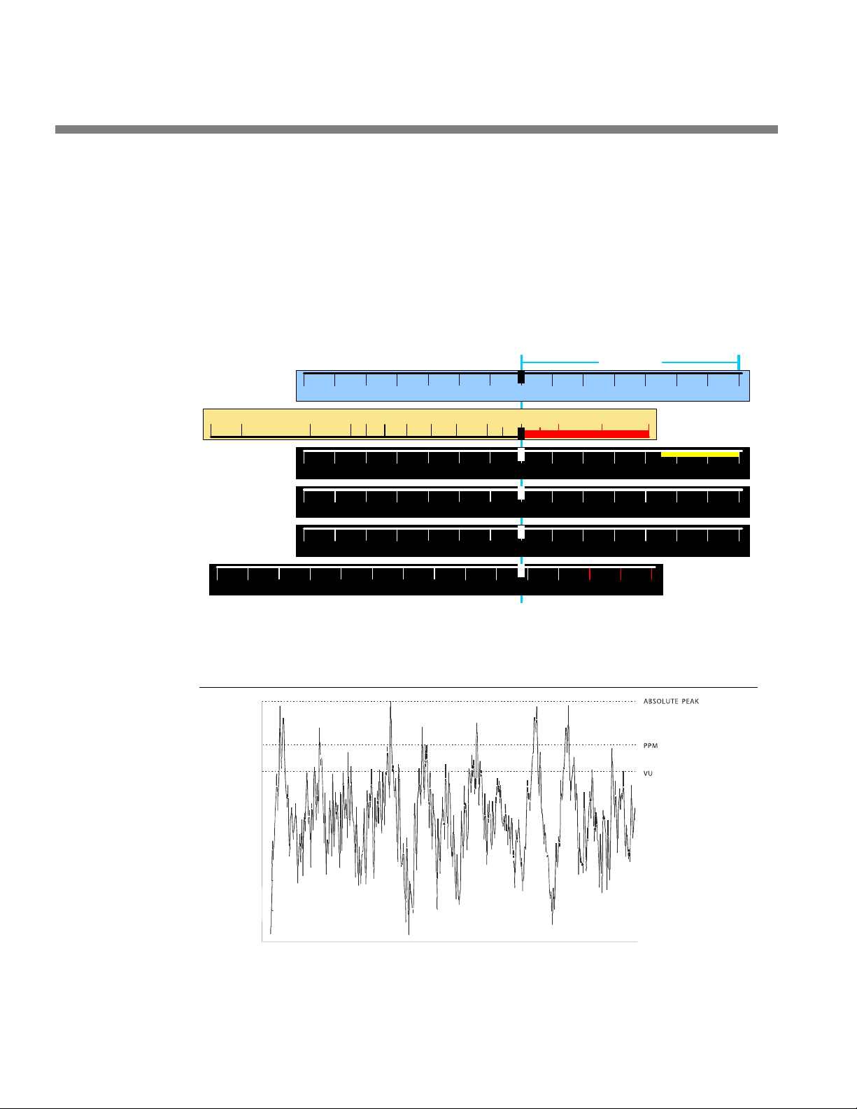
1-22
Figure 1-1: Common Audio Meter Scales, Aligned to the Same Reference Level
-20 -
10 -7
-
5
-3
-
2
-
1 0 +
1 +2
+3
-60
-50 -45
-40 -
35 -30
-25 -
20 -
6
-2
0-
4-
8
-
10-
15
-12 -10 -
8 -6
-4 -
2 0
+8
+
12 14+
10
+
6
+4
+2
1
2 3 4
6 7
5
-50
-30
-
5 +5-
40 0-
10-20
-36
-24 -
18 -12
-6
+6
+12
TEST
-42
0
dBFS
Reference
-
20
dBFS
HEADROOM
INTRODUCTION ORBAN MODEL 8600
In facilities that use PPMs that indicate level directly in dBu, maximum program and
line-up level is often +6dBu. Instantaneous peaks will reach +11dBu or more.
Transmission Levels
The transmission engineer is primarily concerned with the peak level of a program
to prevent overloading or over-modulation of the transmission system. This peak
overload level is defined differently, system to system.
Figure 1-2: Absolute Peak Level, VU and PPM Indications
Page 51
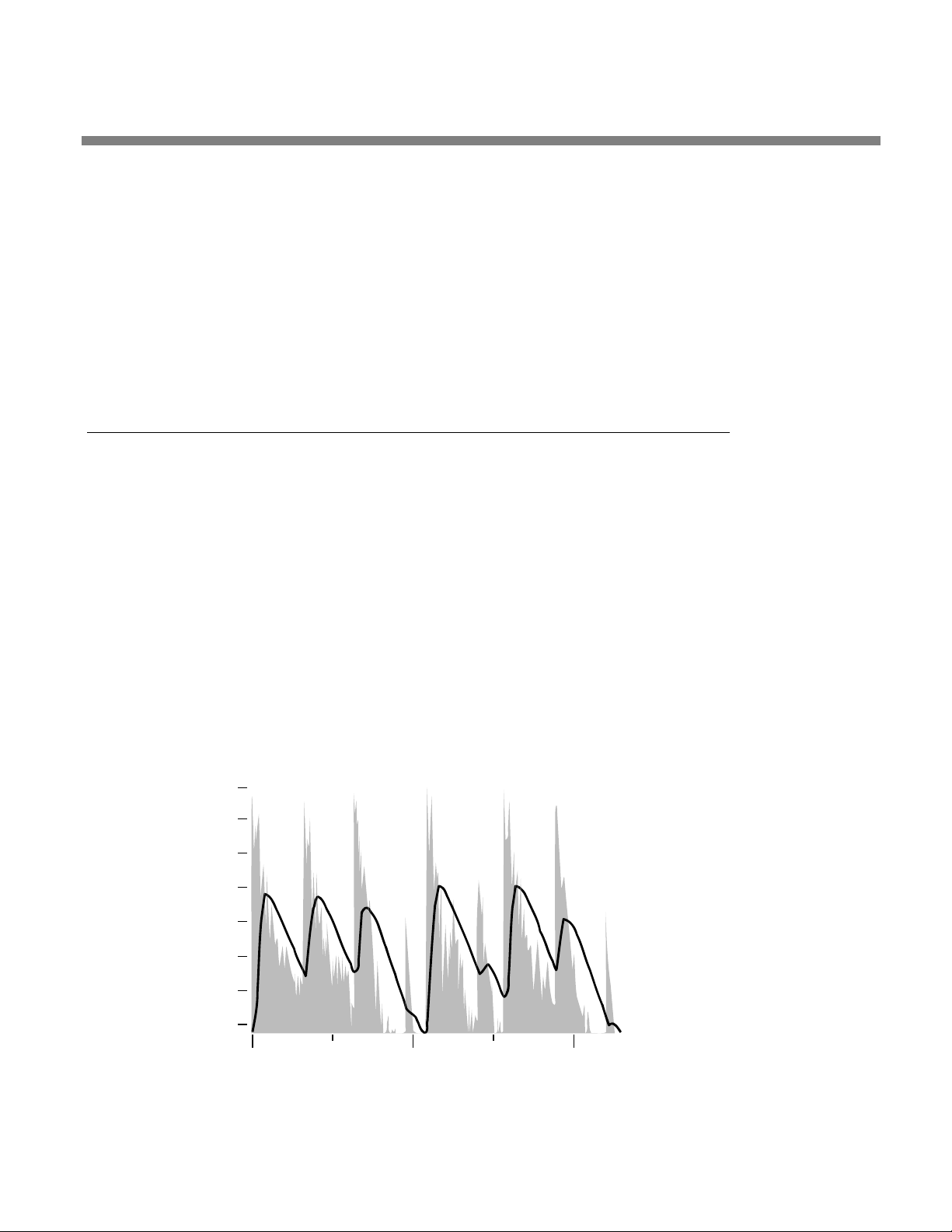
OPTIMOD-FM DIGITAL INTRODUCTION
0
-5
-10
-15
-20
-25
-30
-36
1
2
In FM modulation (FM / VHF radio and television broadcast, microwave or analog
satellite links), it is the maximum-permitted RF carrier frequency deviation. In AM
modulation, it is negative carrier pinch-off. In analog telephone / post / PTT transmission, it is the level above which serious crosstalk into other channels occurs, or
the level at which the amplifiers in the channel overload. In digital, it is the largest
possible digital word.
For metering, the transmission engineer uses an oscilloscope, absolute peak-sensing
meter, calibrated peak-sensing LED indicator, or a modulation meter. A modulation
meter usually has two components—a semi-peak reading meter (like a PPM) and a
peak-indicating light, which is calibrated to turn on whenever the instantaneous
peak modulation exceeds the overmodulation threshold.
Line-Up Facilities
Metering of Levels and Subjective Loudness
The meters on the 8600 show left/right input and output levels and composite modulation. Left and right input level is shown on a VU-type scale (0 to –40 dB), while
the metering indicates absolute instantaneous peak (much faster than a standard
PPM or VU meter). The input meter is scaled so that 0 dB on the scale corresponds
+27 dBu, which is the absolute maximum peak level that the 8600 can accept. If you
are using the AES3 digital input, a full-scale digital word corresponds to the 0 dB
point on the 8600’s input meter.
1-23
Left/right Output Level
Left and right output level is shown on a VU-type scale. The metering indicates absolute instantaneous peak (much faster than a standard PPM or VU meter). The meter
is scaled so that 0 dB is calibrated to the highest left and right peak modulation level, before de-emphasis, that the processing will produce, under any program, pro-
cessing, or setup condition (except when the processing is switched to B
YPASS). The
Figure 1-3: VU Meter Indication Compared to Peak Level vs. Time
Page 52
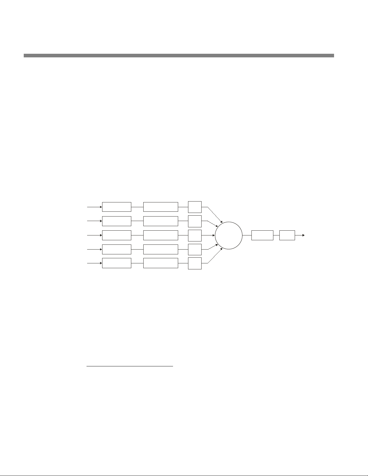
1-24
BS.1770-01
Measured
loudness
x
L
K-filter
Mean square
y
L
G
L
x
R
K-filter
Mean square
y
R
G
R
x
C
K-filter Mean square
y
C
G
C
x
Ls
K-filter
Mean square
y
Ls
G
Ls
x
Rs
K-filter Mean square
y
Rs
G
Rs
z
L
z
R
z
C
z
sL
z
Rs
10 Log
10
Gate
S
INTRODUCTION ORBAN MODEL 8600
meter indication is not affected by the setting of the output level control.
Composite Output Level
The Orban 8600 Audio Processor controls instantaneous, absolute peak levels to a
tolerance of approximately ±0.1 dB. Composite modulation is indicated in percentage modulation, absolute instantaneous peak indicating. 100% is calibrated to the
highest composite peak modulation level that the processing will produce, including
the pilot tone, under any program, processing, or setup condition (except when the
processing is switched to
BYPASS). 100% ordinarily corresponds to ±75 kHz-carrier
deviation.
Note that if the 8600’s subcarrier inputs are used, the meter will not indicate the
subcarriers’ effect on composite modulation because the subcarriers are mixed into
the composite signal in the analog domain, after the composite signal is metered.
Therefore, you must mentally add the subcarriers to the meter indication or refer to
an external, calibrated modulation monitor.
BS.1770 Loudness Level
Figure 1-4: BS.1770 Loudness Meter Block Dia gram (from ITU-R document)
The subjective loudness meters, labeled L
OUDNESS in the 8600’s GUI, display the
loudness at the output of the digital radio processing chain and analog FM pro-
3
cessing chains, measured by the ITU-R BS.1770-3
algorithm.
The loudness meter indicates both BS.1770 Short-Term and Integrated Loudness on
the same scale. The solid bar indicates the Integrated Loudness, while the floating
bar segment indicates the Short-Term Loudness. Per the BS.1770-3 specification, the
3
Recommendation ITU-R BS.1770-3 (08/2012): “Algorithms to measure audio programme loudness and true-peak audio level.” BS.1770-3 first introduced gating to
the loudness meter. For further information about the BS.1770-3 meter, please refer
to the following standards: ITU-R BS.1770, ATSC A/85 EBU R 128, EBU Tech 3341, EBU
Tech 3342, EBU Tech 3343, and EBU Tech 3344. These are free downloads that can be
found easily with a search engine.
Page 53

OPTIMOD-FM DIGITAL INTRODUCTION
integration time of the Short-Term Meter is always 3 seconds, while the Integrated
Meter uses silence gating and its integration time is 10 seconds. Because the meter is
always monitoring program material, it integrates the previous 10 seconds of program material and weights all program material equally within the specified time
window. For example, material occurring 3 seconds in the past and 8 seconds in the
past both contribute equally to the meter’s current indication; newer program material in the specified time window is not favored over older program material.
Because loudness perception combines the contributions of all acoustic sources,
there is only one Loudness Level meter indication for both stereo channels.
The unit of measure in the BS.1770 meter is LKFS or LUFS, which are the same, differing only in nomenclature. A change of 1 LUFS is the same as a change of 1 dB.
In the digital radio chain, “LKFS” and “LUFS” are absolute loudness measurements
with respect to digital full scale. “LK” and “LU” (without the “FS”) are relative loudness measurements, where “0” on the meter corresponds to a user-preset “BS.1770
Reference Level,” which you set via your Optimod’s BS.1770
THRESHOLD control. The BS.1770 meter on your Optimod indicates “LK” or “LU”; you
can choose which label to use via a control available on the HD
SETUP. The other BS.1770-associated controls for digital radio are also there.
I/O
LOUDNESS CONTROL
DIGITAL RADIO tab in
1-25
The meter is scaled so that the loudness level at the consumer’s receiver is correct
when the 8600’s digital radio processing chain is adjusted to make the dominant
program material indicate “0 dB” on the 8600’s Loudness Level meter and the
BS.1770
is equal to that specified by the regulatory authority in your country.
In the analog radio processing chain, the BS.1770 meter and Safety Limiter are calibrated per EBU Tech 3344
produce an FM carrier deviation of ±10 kHz without pilot tone. This corresponds to
13.33% modulation without pilot tone. This calibration includes 50µs transmission
preemphasis. The loudness meter is calibrated so that “0” corresponds to the setting
of the BS.1770
Built-in Calibrated Line-up Tones
To facilitate matching the output level of the 8600 to the transmission system that it
is driving, the 8600 contains an adjustable test tone oscillator that produces sine
waves at 8600’s (analog or digital) left, right, and composite outputs. The frequency
and modulation level of the line-up tones can be adjusted from the front panel (as
described on page 3-84).
The stereo encoder is calibrated so that 100% left or right modulation will provide
100% modulation of the stereo composite signal, including pilot tone, but excluding
any SCA subcarriers.
REFERENCE LEVEL (which you must enter manually) in I/O SETUP > HD RADIO
4
, Section 5.9. This calls for a 1 kHz sinewave at –23 LUFS to
LOUDNESS CONTROL THRESHOLD control in INPUT/OUTPUT > UTILITY.
4
EBU – TECH 3344: “Practical guidelines for distribution systems in accordance with
EBU R 128; Supplementary information for EBU R 128,” available for free download.
Use a search engine to find the latest version.
Page 54

1-26
INTRODUCTION ORBAN MODEL 8600
The pilot tone stereo system has an interleaving property, which means that the stereo composite modulation is approximately equal to the higher of the left or right
channels.
Because the pilot tone is phase-synchronous with the stereo subcarrier,
the composite modulation will actually increase about 2.7% when the
modulation is changed from pure single-channel to L+R modulation
while the peak audio level is held constant.
When the 8600’s left/right analog output is switched to FLAT, a de-emphasis filter is
inserted between output of the 8600’s audio processing and its line output. Thus, as
the frequency of the Test Tone is changed, the level at the 8600’s line output will follow the selected de-emphasis curve. In most cases, the preemphasis filter in the driven equipment will undo the effect of the 8600’s internal de-emphasis, so the 8600’s
output level should be adjusted such that the tone produces 100% modulation of
the transmission link as measured after the link’s preemphasis filter. At 100Hz,
switching the de-emphasis out or in will have negligible effect on the level appearing at the 8600’s left and right audio outputs.
You can adjust the frequency and modulation level of the built-in line-up tone. You
can use the front panel, the PC Control software, or the opto-isolated remote control interface ports to activate the Test Tone.
Built-in Calibrated Bypass Test Mode
YPASS Test Mode is available to transparently pass line-up tones generated earlier
A B
in the system. It will also pass program material, applying no gain reduction or protection against overmodulation. It can transparently pass any line-up tone applied to
its input up to about 130% output modulation, at which point clipping may occur.
Monitoring on Loudspeakers and Headphones
In live operations, highly processed audio often causes a problem with the DJ or
presenter’s headphones. When an “MX” preset is active, the delay through the
8600 can be as much as 270 milliseconds. This delay will be audible as a distinct echo
that almost no one can tolerate in his or her headphones while speaking. The “Multipath Mitigator” phase skew corrector adds about 250 ms of delay.
The 8600 offers two main solutions to this problem:
• Using a non-MX preset, which provides the same algorithms and performance as
Optimod-FM 8500.
• Using the 8600’s low-delay “monitor” output to drive talent headphones.
Because of the need to apply Multipath Mitigator processing equally to
the FM analog and HD processing chains (to ensure seamless crossfades at
the receiver), the Multipath Mitigator is located immediately after the
AGC in the signal path. It therefore adds delay to all presets and to the
monitor output, making it unusable to headphone monitoring. If you
need to use the monitor output to drive headphones, defeat the Multipath Mitigator in Setup.
Page 55

OPTIMOD-FM DIGITAL INTRODUCTION
Using the monitor output is appropriate for both HD Radio and non-HD Radio operations, while using a non-MX preset on-air is only useful in non-HD Radio operations
where no diversity delay has been applied to the analog FM transmission.
Because of their higher performance, we recommend using MX presets in HD Radio
operations. In this context, the preset delay becomes part of the HD Radio diversity
delay and the 8600 automatically compensates for the preset delay to ensure that
the diversity delay always agrees with the value you specified when setting the 8600
up.
With non-MX presets, the normal delay through the 8600 (from input to FM out-
puts) is about 18 ms when H
ARD or MEDIUM bass clipping is selected, as it is in all non-
MX factory presets other than those with “LL” (“low latency”) or “UL” (“ultra-low
latency”) in their names. An 18 ms delay is workable for most talent (although it
may require some acclimatization) because 18 ms is below the psychoacoustic “echo
fusion threshold,” which means that talent will not hear discrete slap echoes in their
headphones. This means that they can monitor comfortably off-air without being
distracted or confused. Moreover, off-air cueing of remote talent is routine.
Some talent moving from an analog processing chain will require a learning period
to become accustomed to the voice coloration caused by “bone-conduction” comb
filtering. This is caused by the delayed headphone sound’s mixing with the live voice
sound, which introduces notches in the spectrum that the talent hears when he or
she talks. All digital processors induce this coloration to a greater or lesser extent.
Fortunately, it does not cause confusion or hesitation in the talent’s performance unless the delay is above the psychoacoustic “echo fusion” (Haas) threshold of approximately 20-25 ms, where the talent starts to hear slap echo in addition to frequency
response colorations.
1-27
Two lower-delay options are available. “Low latency” reduces input-to-FM-output
delay to 13 ms and “ultra-low latency” reduces delay to about 3.7 ms. The trade-off
for this reduction is approximately 1 dB decrease in loudness compared to the 8600’s
full look-ahead processing for low latency and about 2.5 dB loudness decrease for
ultra-low latency.
• When using a non-MX preset, you can invoke the low latency mode by setting
ASSCLIPMODE control (in the CLIPPERS page of ADVANCED CONTROL) to
the B
LLH
ARD. You can also recall a preset with “LL” as part of its name.
LLHARD differs in two ways from the normal HARD mode of the bass clip-
per:
• LLHARD automatically defeats the compressor lookahead. (This action
is functionally equivalent to setting the L
cept that it reduces input/output delay by 5 ms).
• LLHARD prevents the bass clipper from switching to Medium mode
whenever speech is detected. By constraining the system in these
ways, it ensures that the delay is always 13 ms.
Switching the BASSCLIPMODE to LLHARD (from any other mode) removes
five milliseconds of delay from the signal path. If it occurs during program material, switching can cause audible clicks, pops, or thumps (due
OOKAHEAD control to OUT, ex-
Page 56

1-28
INTRODUCTION ORBAN MODEL 8600
to waveform discontinuity). If you have some presets with LLHARD bass
clipper mode and some without, switching between these presets is likely
to cause clicks unless you do it during silence. However, these clicks will
never cause modulation to exceed 100%.
One of the essential differences between the H
per modes is that switching between H
lay and is therefore less likely to cause audible clicks.
ARD and MED does not change de-
ARD and LLHARD bass clip-
• Ultra-low latency processing uses a separate, parallel processing structure and is
invoked by recalling any “UL” preset. This structure operates simultaneously with
other code, so, unlike the similar structure in Orban’s Optimod 8300, it does not
require a code re-load and does not cause a gap in programming.
The only way to create an ultra-low latency user preset is to start with a
“UL” factory preset and then edit that preset. “UL” user presets cannot
be directly converted to low latency or optimum latency presets because
the preset customization controls are different—UL presets have fewer
available controls because of the difference in processing structure.
UL presets are the closest emulations of Optimod 8200 processing available in the 8600. These presets differ from Optimod 8200 processing in
two main ways: (1) the 8600 UL presets still use the 8600’s stereo enhancement, equalization section, advanced-technology AGC, composite
limiter, and multiplex power controller, and (2) the 8600 UL presets use
anti-aliased clippers operating at 256 kHz sample rate.
Some talent moving from an analog processing chain will require a learning period
to become accustomed to the voice coloration caused by “bone-conduction” comb
filtering. This is caused by the delayed headphone sound’s mixing with the live voice
sound and introducing notches in the spectrum that the talent hears when he or she
talks. All digital processors induce this coloration to a greater or lesser extent. Fortunately, it does not cause confusion or hesitation in the talent’s performance unless
the delay is above the psychoacoustic “echo fusion” (Haas) threshold of approximately 20 - 25 ms and the talent starts to hear slap echo in addition to frequency response colorations.
Low-Delay Monitoring
The 8600’s analog outputs can be switched to provide a low-delay monitoring
feed (see step 15 on page 2-39). This feed has no peak limiting and thus cannot
drive a transmitter, but its 3 to 8 ms delay is likely to be more comfortable to talent
than the 18 ms delay of the full processing chain because of less bone conduction
comb filtering.
If the talent relies principally on headphones to determine whether the station is on
the air, simple loss-of-carrier and loss-of-audio alarms should be added to the system. The 8600 can be interfaced to such alarms through any of its eight its GPI remote control inputs, cutting off the low-delay audio to the talent’s phones when an
audio or carrier failure occurs.
The front panel headphone jack provides output matching the Analog Output, except that it is always de-emphasized (even if the Analog Output is set with
preemphasis).
Page 57

OPTIMOD-FM DIGITAL INTRODUCTION
Because of system architecture, it is necessary to include the Multipath
Mitigator/Phase Corrector in the signal path before the low delay monitor output. If this is activated in I/O Setup (step 8 on page 2-32), it adds
about 250 ms delay, and the “low delay” output will no longer be usable
for its intended purpose. If you use the Phase Corrector, we recommend
using a separate monitor processor (like an old analog Optimod-FM) for
headphones.
EAS Test
For stations participating in the Emergency Alert System (EAS) in the United States,
broadcast of EAS tones and data is accomplished in two different ways:
Note: Normal 8600 processing may not allow the full modulation level as required by EAS standards. It is therefore necessary to temporarily defeat the
8600’s processing during the broadcast of EAS tones and data. Placing the 8600
in its B
lows a fixed gain trim through the 8600. See “Test Modes,” on page 3-84 for
more information.
1. Place the 8600 in Bypass mode locally.
YPASS Test Mode can defeat the processing. The BYPASS GAIN control al-
1-29
OCATE to SYSTEM SETUP on the pop-up Menu display, then press ENTER but-
A) L
ton.
B) Select T
C) L
OCATE to BYPASS, then press ENTER button.
EST MODES > LOCATE to TEST MODES icon and press ENTER button.
D) Begin EAS broadcast.
After the EAS broadcast, resume normal processing:
E) L
OCATE to OPERATE in the Test Modes screen, then press ENTER button.
This will restore the processing preset in use prior to the Test Mode.
2. Place the 8600 in Bypass mode by remote control.
To do this, you must first program any two Remote Interface inputs for “Bypass”
and “Exit Test,” respectively:
A) Connect two outputs from your station remote control system to the R
INTERFACE connector on the rear panel of the 8600. See Figure 2-2 on page 2-
4.
OCATE to SYSTEM SETUP on the pop-up Menu display, then press ENTER but-
B) L
ton.
C) Select N
NTER button.
E
ETWORK REMOTE > LOCATE to NETWORK REMOTE MODES icon and press
EMOTE
D) Press and hold L
OCATE right to the System Setup > Network / Remote 2 screen.
E) Select the desired Remote Interface input (1-8), using L
F) Turn the control knob to display B
YPASS, then press the ENTER button.
OCATE button.
Page 58

1-30
INTRODUCTION ORBAN MODEL 8600
G) L
OCATE to a different Remote Interface input, turn the control knob to display
XIT TEST, then press the ENTER button.
E
Once you have completed these initial steps, you can place the 8600 in Bypass
mode by remote control at any time:
A) Switch the 8600 into B
tion’s remote control to the input programmed as B
B) Begin EAS broadcast.
Be sure that you have set drive levels into the 8600 to prevent overmodulation during the test, as the 8600 provides no peak limiting in BYPASS
mode.
C) When the EAS broadcast is finished, switch the 8600 from BYPASS mode by a
momentary command from your station’s remote control to the input pro-
grammed as E
You may also choose to insert EAS broadcast tones and data directly into the transmitter, thus bypassing the 8600 for the duration of the EAS tones and data broadcast.
XIT TEST.
YPASS mode by a momentary command from your sta-
YPASS.
PC Control and Security Passcode
PC software control provides access to OPTIMOD-FM via network, modem or direct
(null modem cable) connection, with IBM PC-compatible computers running Windows. PC access is permitted only with a valid user-defined passcode.
PC remote control can be ended from the front panel; this feature effectively prevents simultaneous remote and local control.
See Security and Passcode Programming on page 2-44.
Warranty, User Feedback
User Feedback
We are very interested in your comments about this product. We will carefully review your suggestions for improvements to either the product or the manual. Please
email us at [email protected].
LIMITED WARRANTY
[Valid only for products purchased and used in the United States]
Orban warrants Orban products against defects in material or workmanship for a
period of five years from the date of original purchase for use, and agrees to repair
or, at our option, replace any defective item without charge for either parts or labor.
Page 59

OPTIMOD-FM DIGITAL INTRODUCTION
IMPORTANT: This warranty does not cover damage resulting from accident, misuse
or abuse, lack of reasonable care, the affixing of any attachment not provided with
the product, loss of parts, or connecting the product to any but the specified receptacles. This warranty is void unless service or repairs are performed by an authorized
service center. No responsibility is assumed for any special, incidental, or consequential damages. However, the limitation of any right or remedy shall not be effective
where such is prohibited or restricted by law.
Simply take or ship your Orban products prepaid to our service department. Be sure
to include a copy of your sales slip as proof of purchase date. We will not repair
transit damage under the no-charge terms of this warranty. Orban will pay return
shipping. (See Technical Support on page 5-12.)
No other warranty, written or oral, is authorized for Orban Products.
This warranty gives you specific legal rights and you may have other rights that vary
from state to state. Some states do not allow the exclusion of limitations of incidental or consequential damages or limitations on how long an implied warranty
lasts, so the above exclusions and limitations may not apply to you.
1-31
INTERNATIONAL WARRANTY
Orban warrants Orban products against evident defects in material and workmanship for a period of five years from the date of original purchase for use. This warranty does not cover damage resulting from misuse or abuse, or lack of reasonable
care, or inadequate repairs performed by unauthorized service centers. Performance
of repairs or replacements under this warranty is subject to submission of this Warranty/Registration Card, completed and signed by the dealer on the day of purchase,
and the sales slip. Shipment of the defective item is for repair under this warranty
will be at the customer’s own risk and expense. This warranty is valid for the original
purchaser only.
Page 60

Page 61

OPTIMOD-FM DIGITAL INSTALLATION
B) Save all packing materials! If you should ever have to ship the 8700 (e.g., for
I
Section 2
Installation
Installing the 8600
Allow about 2 hours for installation.
Installation consists of: (1) unpacking and inspecting the 8600, (2) checking the line
voltage setting, fuse, and power cord, (3) mounting the 8600 in a rack, (4) connecting inputs, outputs and power, (5) optional connecting of remote control leads and
(6) optional connecting of computer interface control leads.
When you have finished installing the 8600, proceed to “Quick Setup,” on page 2-
18.
2-1
DO NOT connect power to the unit yet!
1. Unpack and inspect.
A) If you note obvious physical damage, contact the carrier immediately to make
a damage claim. Packed with the 8600 are:
Quantity Item
1 Operating Manual
2 Line Cords (domestic, European)
2 Fuses (½ A-250V Slow-Blow for 115V; 250 mA-250V for 230V)
2 Fuse holders (gray for 115V fuses and black for 230V fuses)
4 Rack-mounting screws, 10-32 x ¾—with washers, #10
1 Null modem cable (for software upgrades and PC Remote connection)
1 Ethernet crossover cable
1 PC Remote Software CD
servicing), it is best to ship it in the original carton with its packing materials
because both the carton and packing material have been carefully designed
to protect the unit.
C) Complete the Registration Card and return it to Orban. (please)
The Registration Card enables us to inform you of new applications, performance improvements, software updates, and service aids that may be
developed and it helps us respond promptly to claims under warranty
Page 62
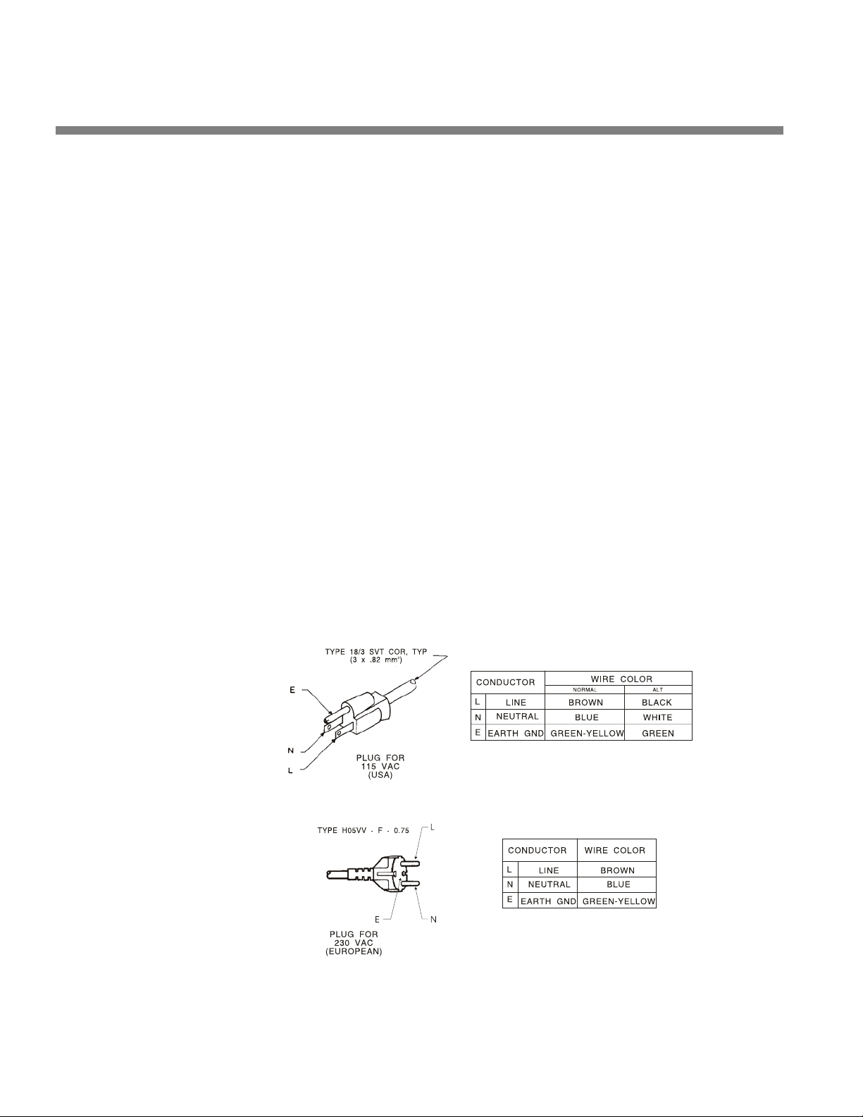
2-2
INSTALLATION ORBAN MODEL 8600
without our having to request a copy of your bill of sale or other proof of
purchase. Please fill in the Registration Card and send it to us today. (The
Registration Card is located after the cover page).
Customer names and information are confidential and are not sold to
anyone.
2. Check the line voltage, fuse and power cord.
We strongly recommend powering your Optimod from an Uninterruptable Power Supply (UPS). This will protect your Optimod from damage caused by line
surges and will prevent audio interruptions caused by brownout-induced reboots.
A) DO NOT connect power to the unit yet!
B) Check the V
The 8600 is shipped from the factory with the V
to the 230V position. Check and set the V
local voltage requirements. To change the operating voltage, set the
OLTAGE SELECT to 115V (for 90-130V) or 230V (for 200-250V) as appro-
V
priate.
C) Install the proper fuse and fuse holder, per your country’s standards.
The 8600 is shipped from the factory with the fuse and fuse holder removed. Select the appropriate fuse holder and fuse from the supplied
parts in the accessory kit. Use the gray fuse holder for domestic / 115V
operation, or the black fuse holder for European / 230V operation. For
safety, use ½ A-250 V Slow-Blow for 115V and 250mA-250V for 230V for
230V.
OLTAGE SELECT switch. This is on the rear panel.
OLTAGE SELECT switch set
OLTAGE SELECT switch to your
Figure 2-1: AC Line Cord Wire Standard)
Page 63

OPTIMOD-FM DIGITAL INSTALLATION
D) Check power cord.
AC power passes through an IEC-standard mains connector and an RF filter designed to meet the standards of all international safety authorities.
The power cord is terminated in a “U-ground” plug (USA standard), or
CEE7 / 7 plug (Continental Europe). The green / yellow wire is connected
directly to the 8600 chassis.
If you need to change the plug to meet your country’s standard and you
are qualified to do so, see Figure 2-1: AC Line Cord Wire Standard). Otherwise, purchase a new mains cord with the correct line plug attached.
3. Mount the 8600 in a rack.
The 8600 requires three standard rack units (5 inches / 12.7 cm).
There should be a good ground connection between the rack and the 8600 chassis—check this with an ohmmeter to verify that the resistance is less than 0.5Ω.
Mounting the unit over large heat-producing devices (such as a vacuum-tube
power amplifier) may shorten component life and is not recommended. Ambient
temperature should not exceed 45°C (113°F) when equipment is powered.
2-3
Equipment life will be extended if the unit is mounted away from sources of vibration, such as large blowers and is operated as cool as possible.
4. Connect inputs and outputs.
See the hookup and grounding information on the following pages.
Audio Input and Output Connections ............................................................ Page 2-6
AES3 Digital Input and Output ....................................................................... Page 2-7
Connecting a Ratings Encoder ........................................................................ Page 2-8
Composite Output and Subcarrier Inputs ...................................................... Page 2-9
Grounding ...................................................................................................... Page 2-12
5. Connect remote control interface. (optional)
For a full listing of 8600’s extensive remote control provisions, refer to “Remote Control Interface Programming” on page 2-60.
Optically isolated remote control connections are terminated in a type DB-25 male
connector located on the rear panel. It is wired according to Figure 2-2.
To select the desired function, apply a 5-12V AC or DC pulse between the appropriate Remote Interface terminals. The (−) terminals can be connected together and
then connected to power common at pin 1 to create a Remote Common. A currentlimited +12VDC source is available on pin 25. If you use 48V, connect a 2kΩ ±10%, 2watt carbon composition resistor in series with the Remote Common or the (+) terminal to provide current limiting.
In a high-RF environment, these wires should be short and should be run through
foil-shielded cable, with the shield connected to CHASSIS GROUND at both ends.
Page 64
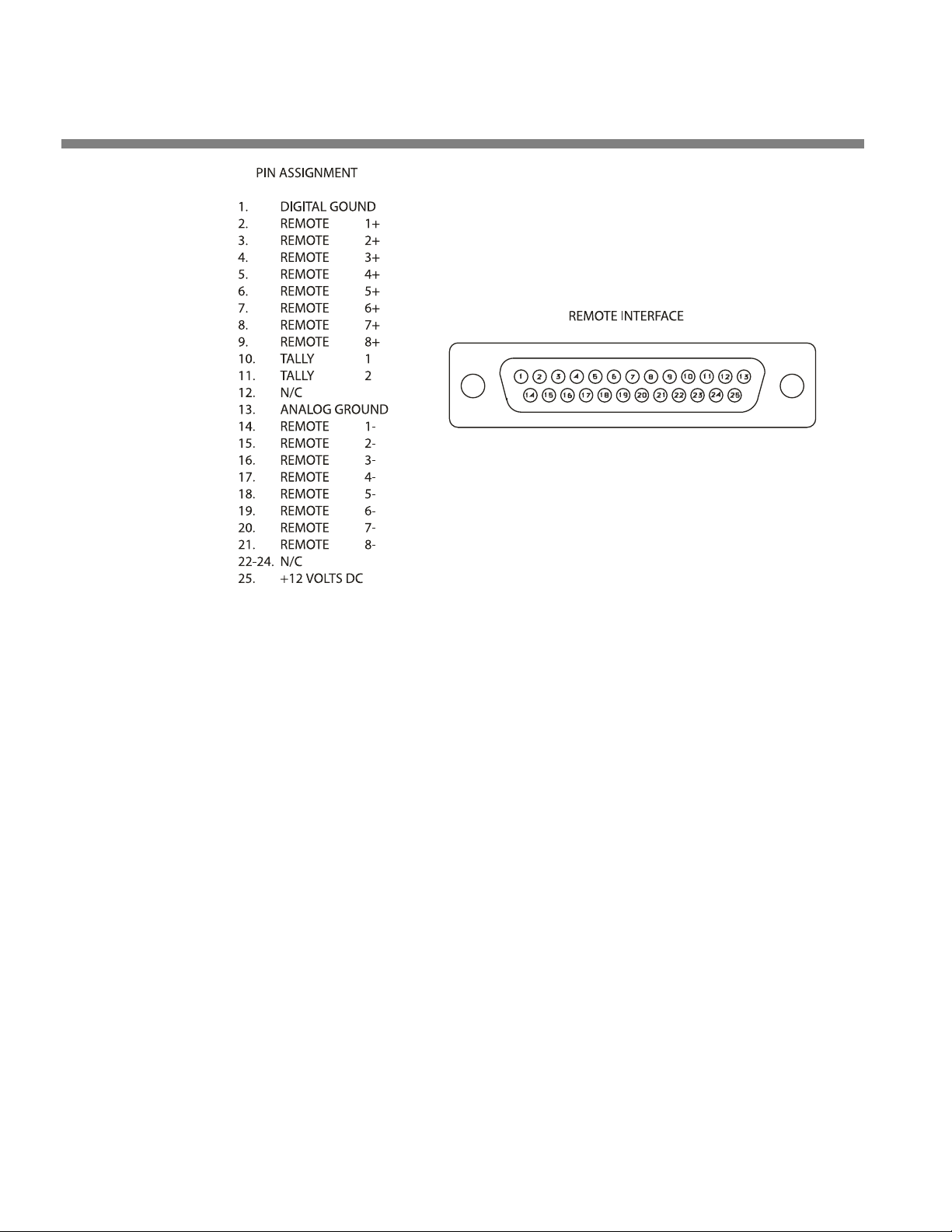
2-4
I
impedance
voltage source! The tally outputs are not protected against this
INSTALLATION ORBAN MODEL 8600
Figure 2-2: Wiring the 25-pin Remote Interfac e Connector
6. Connect tally outputs (optional)
See the schematic on page 6-42.
There are two tally outputs, which are NPN open-collector and operate with respect to pin 1 (common). Therefore, the voltage applied to the load (such as a relay or optoisolator) must be positive. You can use the 12 VDC source on pin 25 to
drive the high side of the load, taking into account the fact that the voltage on
pin 25 is current limited by a 310 Ω resistor.
The tally outputs are protected against reverse polarity.
To avoid damaging the 8600, limit the current into a tally output to
30 mA. DO NOT connect a tally output directly to a low-
Note that the tally outputs have no special RFI protection. Therefore, it is wise to
use shielded cable to make connections to them.
See Tally Output Programming on page 2-62 for instructions on using the tally
outputs.
abuse and Q3 or Q4 is likely to burn out.
Page 65

OPTIMOD-FM DIGITAL INSTALLATION
7. Connect to a computer
You can connect to a computer via the 8600’s serial connector or via an Ethernet
network. (See Networking on page 2-63.)
See Installing 8600 PC Remote Control Software on page 2-66 for more detail.
8600 Rear Panel
The Voltage Select switch can be set to 115V (for 90-130V operation) or 230V (for
180-260V operation).
Fuse values can be changed to support 115V or 230V operation. For safety, use ½ A250V Slow-Blow for 115V and 250 mA-250V for 230V.
The Power Cord is detachable and is terminated in a “U-ground” plug (USA stand-
ard), or CEE7 / 7 plug (Continental Europe), as appropriate to your 8600’s Model
Number.
An RS-232 (PC Remote) Computer Interface, labeled Serial 1, is provided to
connect the 8600 to IBM PC-compatible computers, directly or via modem, for remote control, metering and software downloads. An additional RS-232 port, labeled
Serial 2, can be used for administering security and for recalling presets via simple
ASCII strings. See Administering the 8600 through its Serial Ports or Ethernet on
page 2-48.
2-5
A Remote Interface Connector is provided to connect the 8600 to your existing
transmitter remote control. The 8600 remote control supports user-programmable
selection of up to eight optically isolated GPI inputs. The 8600 remote control accepts a DB-25 connector.
For a list and description of the programmable GPI functions, see Remote
Control Interface Programming on page 2-60.
The Ethernet port is a female RJ45 connector for use with CAT5 cable in 100 Mbps
Ethernet networks running the TCP/IP protocol. Use a normal Ethernet cable to connect the port to a switch or hub, or a crossover Ethernet cable to connect it directly
to your computer’s Ethernet port. See Networking and Remote Control on page 2-
63.
Digital AES3 Input and Outputs are provided to support two-channel AES3-
standard digital audio signals through XLR-type connectors. In addition, an AES11
Sync Input is provided to accept house sync, if required.
Analog Inputs and Outputs are provided to support left and right audio signals
through XLR-type connectors. The digital outputs and the analog output can all be
independently switched to emit the FM-processed signal, the digital radio processed
signal, or the low-delay monitor signal.
Two Composite Baseband Outputs are provided, each with independent output
level control. Each output uses a BNC connector.
Page 66

2-6
INSTALLATION ORBAN MODEL 8600
Two SCA Inputs are provided for stations that use additional subcarriers (SCAs).
Each input uses a BNC connector. The second SCA input can be reconfigured via an
internal hardware jumper as a Pilot Reference Output useful for RDS (RBDS) subcarrier generators that require an external sync reference.
Audio Input and Output Connections
Cable
We recommend using two-conductor foil-shielded cable (such as Belden 8451 or
equivalent), because signal current flows through the two conductors only. The
shield does not carry signal and is used only for shielding.
Connectors
• Input and output connectors are XLR-type connectors.
In the XLR-type connectors, pin 1 is CHASSIS GROUND, while pin 2 and
pin 3 are a balanced, floating pair. This wiring scheme is compatible with
any studio-wiring standard: If pin 2 or 3 is considered LOW, the other pin
is automatically HIGH.
Analog Audio Input
• The 8600 will operate normally with nominal input levels between –14 dBu and
+8 dBu.
(0 dBu = 0.775Vrms. For this application, the dBm @600Ω scale on voltmeters can be read as if it were calibrated in dBu.)
• The peak input level that causes overload depends on the setting of the Analog
Input C
• The electronically balanced input uses an ultra low noise and distortion differen-
tial amplifier for best common mode rejection. It is compatible with most professional and semi-professional audio equipment, balanced or unbalanced, having
a source impedance of 600Ω or less. The input is EMI suppressed.
• Input connections are the same whether the driving source is balanced or unbal-
anced.
• Connect the red (or white) wire to the pin on the XLR-type connector (#2 or #3)
that is considered HIGH by the standards of your organization. Connect the
black wire to the pin on the XLR-type connector (#3 or #2) that is considered
LOW by the standards of your organization.
LIP LEVEL control. It is adjustable from 0 dBu to +27.0 dBu.
• In low RF fields (like a studio site), connect the cable shield at 8600 input only—it
should not be connected at the source end. In high RF fields (like a transmitter
Page 67

OPTIMOD-FM DIGITAL INSTALLATION
site), also connect the shield to pin 1 of the male XLR-type connector at the 8600
input.
• If the output of the driving unit is unbalanced and does not have separate
CHASSIS GROUND and (–) (or LOW) output terminals, connect both the shield
and the black wire to the common (–) or ground terminal of the driving unit.
Analog Audio Output
• Electronically balanced and floating outputs simulate a true transformer output.
The source impedance is 50Ω. The output can drive loads of 600Ω or higher; the
Analog O
+24 dBu range. The outputs are EMI suppressed.
• If an unbalanced output is required (to drive unbalanced inputs of other equip-
ment), take it between pin 2 and pin 3 of the XLR-type connector. Connect the
LOW pin of the XLR-type connector (#3 or #2, depending on your organization’s
standards) to circuit ground and take the HIGH output from the remaining pin.
No special precautions are required even though one side of the output is
grounded.
UT LEVEL control adjusts the 100% modulation level over a –6 dBu to
2-7
• Use two-conductor foil-shielded cable (Belden 8451, or equivalent).
• At the 8600’s output (and at the output of other equipment in the system), do
not connect the cable’s shield to the CHASSIS GROUND terminal (pin 1) on the
XLR-type connector. Instead, connect the shield to the input destination. Connect the red (or white) wire to the pin on the XLR-type connector (#2 or #3) that
is considered HIGH by the standards of your organization. Connect the black
wire to the pin on the XLR-type connector (#3 or #2) that is considered LOW by
the standards of your organization.
AES3 Digital Input and Output
In a standard 8600, there are two digital inputs and two digital outputs. One input
accepts program audio; the other accepts AES11 house sync, although sync is not required. Either output can be programmed to emit the signal intended for the analog FM channel and/or the signal intended for the digital channel.
If you intend to use the BS.1770 Safety Limiter to drive a digital radio chain, we suggest that you use Digital Output 1 to drive the digital radio transmitter. The BS.1770
safety limiter in the analog processing chain is calibrated with reference to 100%
modulation (see page 1-25) and is usable with the analog, digital, and composite
outputs.
The program input and output are both equipped with sample rate converters and
can operate at 32 kHz, 44.1 kHz, 48 kHz, 88.2 kHz, and 96 kHz.
Page 68

2-8
INSTALLATION ORBAN MODEL 8600
Per the AES3 standard, each digital input or output line carries both the
left and right stereo channels. The connection is 110Ω balanced. The
AES3 standard specifies a maximum cable length of 100 meters. While
almost any balanced, shielded cable will work for relatively short runs (5
meters or less), longer runs require used of 110Ω balanced cable like
Belden 1800B, 1801B (plenum rated), multi-pair 180xF, 185xF, or 78xxA.
Single-pair category 5, 5e, and 6 Ethernet cable will also work well if you
do not require shielding. (In most cases, the tight balance of Category
5/5e/6 cable makes shielding unnecessary.)
The AES3id standard is best for very long cable runs (up to 1000 meters).
This specifies 75Ω unbalanced coaxial cable, terminated in BNC connectors. A 110Ω/75Ω balun transformer is required to interface an AES3id
connection to your Optimod’s digital input or output.
The digital input clip level is fixed at 0 dB relative to the maximum digital word. The
maximum digital input will make the 8600 input meters display 0 dB. The reference
level is adjustable using the Digital R
The 8600 is a “multirate” system whose internal sample rate is 64 kHz and multiples
thereof (up to 512 kHz). The outputs processed for analog FM are band-limited to
16.5 kHz, with a stopband that begins at 18 kHz. Therefore, the output can be
passed through a 44.1 kHz (or higher) uncompressed link without adding significant
overshoot. Because sample rate conversion is ordinarily a phase-linear process that
does not add bandwidth, the 8600’s output signal will continue to be compatible
with 44.1 kHz links even if it undergoes intermediate sample rate conversions (for
example, 44.1 kHz to 96 kHz to 44.1 kHz) at various points in the program chain.
EFERENCE LEVEL control.
The audio bandwidth of the AES output dedicated to the HD-processed signal is adjustable from 15 kHz to 20 kHz in 1 kHz steps.
Connecting a Ratings Encoder
This allows a ratings encoder having AES3 inputs and outputs to be driven from your
Optimod’s DIGITAL OUTPUT #2, while the rating encoder’s output drives your Optimod’s SYNC INPUT. The ratings encoder may be embedded in one of two places:
• At the output of the AGC before the analog-FM and HD processing paths split,
allowing a single ratings encoder to be used for both the analog FM and HD
channels while still receiving level-controlled audio. Set the AES
trol to AGC>R
• Between your Optimod’s left/right audio processing and stereo encoder, main-
taining consistently high audio drive levels into the ratings encoder while allow-
ing your Optimod’s composite limiter to be used. Set the AES
to L
IMIT>RATINGS in PC Remote or LIM>RE on the Optimod.
In Rating Encoder mode, if a valid AES3 signal is not detected at its SYNC input, your
Optimod will automatically bypass the loop-through. While this will prevent dead
air, it means that ratings encoding will not be applied to your broadcast.
ATINGS in PC Remote or AGC>RE on the Optimod.
2 SOURCE con-
2 SOURCE control
Page 69

OPTIMOD-FM DIGITAL INSTALLATION
Because of the importance of proper ratings encoder operation, your Optimod will
flash a warning on its screen and on PC Remote if it enters the fallback mode. This
will help detect potential failures in the ratings encoder hardware.
All 8600 units manufactured before April 2013 require a minor hardware modification to support ratings encoder loop-through operation. The modification consists
of adding one jumper and removing one resistor. Field Engineering Bulletin #2,
downloadable from ftp.orban.com/8600/Field_Engineering_Bulletins, provides re-
work instructions.
CAUTION: You will be working on a surface-mount circuit board, so to avoid damaging the circuit board you must perform the rework with tools and procedures compatible with surface-mount rework. Do not attempt the rework if you are not skilled
in these procedures. Your warranty does not cover damage caused by incorrect rework tools or procedures.
Orban can perform this rework for a flat fee of $100. If you are in doubt, please contact Orban customer service to obtain a Return Authorization. See Technical Support
starting on page 5-12.
2-9
Composite Output and Subcarrier Inputs
There are two composite outputs. These carry the encoded stereo signal, the ste-
reo pilot tone, and any subcarriers that may have been applied to the 8600’s subcarrier inputs.
Each output’s level is independently adjustable from –13.7 dBu to +10.6 dBu.
The output impedance of composite output #1 and composite output #2 can be set
to 0Ω or 75Ω via jumpers J2 and J3 respectively (located on the I/O Board). As
shipped, the link is on pins 3 and 4, yielding 0 Ω impedance. To reset a given output
to 75Ω, place the link on pins 1 and 2 of its associated jumper. (See the schematic on
page 6-56 and the parts locator diagram on page 6-53.)
Each output can drive up to 75Ω in parallel with 0.047µF before performance deteriorates significantly (see Figure 2-3on page 2-10).
Connect the 8600’s composite output to the exciter input with up to 100 feet
(30.5m) of RG-58 / U or RG-59 / U coaxial cable terminated in BNC connectors.
Longer runs of coax may increase problems with noise, hum, and RF
pickup at the exciter. In general, the least troublesome installations place
the 8600 close to the exciter and limit the length of the composite cable
to less than 6 feet (1.8m).
We do not recommend terminating the exciter input by 50Ω or 75Ω unless this is unavoidable. The frequencies in the stereo baseband are low
by comparison to RF and video and the characteristic impedance of coaxial cable is not constant at very low frequencies. Therefore, the transmission system will usually have more accurate amplitude and phase response (and thus, better stereo separation) if the coax is driven by a very
low impedance source and is terminated by greater than 1kΩ at the ex-
Page 70
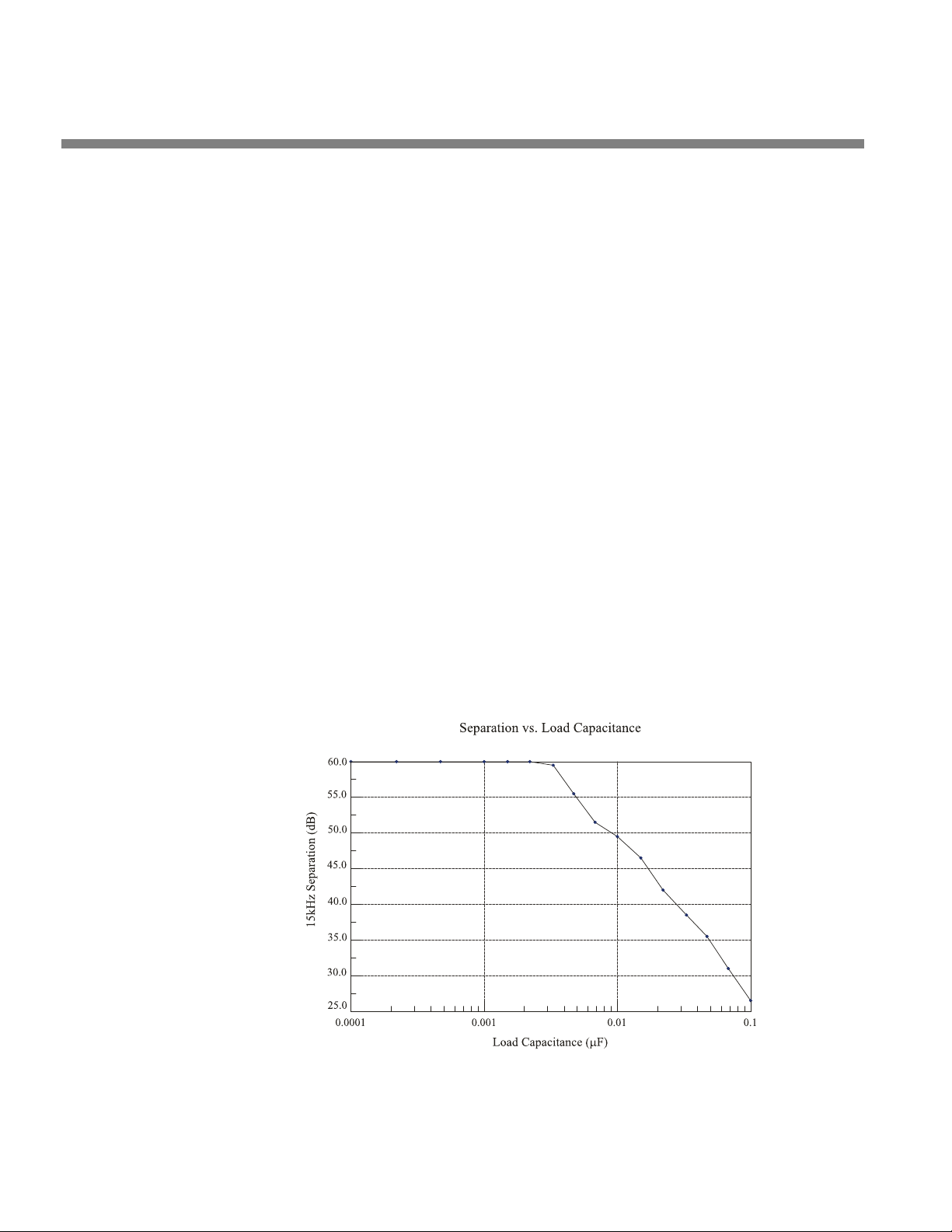
2-10
INSTALLATION ORBAN MODEL 8600
citer end. This also eases thermal stresses on the output amplifier in the
stereo encoder and can thus extend equipment life.
If a composite isolation transformer is used to break a ground loop, the
exciter must present a 1kΩ or greater load to the transformer for proper
transformer operation. See page 1-15.
Even when its composite limiter is being used heavily, the 8600 will always protect the stereo pilot tone by at least 60 dB (±250Hz from 19 kHz)
and will protect the region from 55 kHz to 100 kHz by at least 75 dB (re
100% modulation). See Figure 5-1 on page 5-4.
The subcarrier inputs are provided for convenience in summing subcarriers into
the baseband prior to their presentation to the FM exciter.
The subcarrier inputs will accept any subcarrier (or combinations of subcarriers) above 23 kHz. Below 5 kHz, sensitivity rolls off at 6 dB/octave to
suppress hum that might otherwise be introduced into the subcarrier inputs, which are unbalanced.
The subcarrier inputs are mixed into the 8600’s composite output in the
analog domain, after D/A conversion of the 8600 stereo encoder’s output
but before the digitally controlled attenuators that set the composite
output levels.
As shipped from the factory, the second SCA connector emits a stereo pilot tone
reference for RDS or RBDS subcarrier generators. If you wish to reconfigure it to accept an SCA signal, move the link on jumper J400 (on the I/O board) from pins 3 and
4 to pins 1 and 2.
To access J400, remove the 8600’s top cover according to the instructions
in step 1 on page 4-2. To find J400, see page 6-53 for the I/O board parts
locator drawing. To find the I/O board, see the circuit board locator
Figure 2-3: Separation vs. load capacitance
Page 71

OPTIMOD-FM DIGITAL INSTALLATION
drawing on page 6-37. The schematic diagram showing J400 is on page 6-
56.
Connect your subcarrier generator(s) to the 8600’s subcarrier input(s)
with coaxial cable terminated with BNC connectors.
The subcarrier inputs have greater than 600Ω load impedance and are
unbalanced. Their sensitivity is variable from 220 mV p-p to > 10 V p-p to
produce 10% injection via trimmers that are accessible for screwdriver
adjustment through holes in the rear panel.
Using the P
screen), you can set the phase of the reference to 0°, 90°, 180°, or 270°
with respect to the pilot tone appearing at the composite output.
ILOT REFERENCE control (in the INPUT/OUTPUT > COMPOSITE
You can use the 19K REF control in SETUP to determine whether the 19 kHz pilot
reference output will be in-phase (0
site output or will lead it by 90 degrees (90
tions. Use 90
DEG only if your RDS/RBDS generator’s 19 kHz reference input specifi-
DEG) with the pilot tone present in the compo-
DEG). 0 DEG is correct for most installa-
cally requires this phase relationship.
Digital Composite Outputs
In MPX hardware, there is also an AES3 digital composite output at 192 kHz sample
rate. Its output level is set in the Input/Output 5 screen titled Composite 2. At the PC
remote, it is located in the I/O
SETUP SCREEN with the tab DIGITAL ENCODER.
2-11
This output appears on a male XLR-type connector on the breakout cable supplied
with your Optimod. This output is fully compatible with and interoperable with the
de-facto industry standard digital connection being implemented by transmitter
manufacturers and others.
Digitized Subcarrier Inputs
In MPX hardware, two additional subcarrier inputs are provided on the breakout
cable. These are digitized and are summed only into the digital composite output.
Their mix level is set in the Input/Output 5 screen titled Composite 2. At the PC re-
mote, they are located in the I/O
SETUP SCREEN with the tab DIGITAL ENCODER.
If you need to use both the digital and analog composite outputs, you must split the
outputs of your SCA generators with Y cables so that each generator output drives
one digitized SCA input and one non-digitized SCA input.
Wordclock/10 MHz Sync Reference Input
The sync reference input (labeled R
EF IN) appears on a female BNC jack at the end of
the breakout cable that connects to the digital composite connector. It is available
only on MPX hardware. It accepts a 1x 5V p-p squarewave wordclock signal at 32,
44.1, 48, 88.2, or 96 kHz, or a 10 MHz sinewave or squarewave signal, 0.5 to 5 V
peak. 10 MHz is a common output frequency produced by GPS and rubidium frequency standards. You can configure the 8600 to lock its 19 kHz pilot tone and output sample frequency to this input.
Page 72

2-12
INSTALLATION ORBAN MODEL 8600
When a valid reference signal is applied to this input, it locks the Optimod’s Internal
DSP clock to this input, so if a given AES3 L/R output’s sync source is set to I
the sample frequency at that output will be locked to this reference signal.
Do not apply an AES3 signal to this input.
NTERNAL,
Grounding
Very often, grounding is approached in a “hit or miss” manner. Nevertheless, with
care it is possible to wire an audio studio so that it provides maximum protection
from power faults and is free from ground loops (which induce hum and can cause
oscillation).
In an ideal system:
• All units in the system should have balanced inputs. In a modern system with low
output impedances and high input impedances, a balanced input will provide
common-mode rejection and prevent ground loops—regardless of whether it is
driven from a balanced or unbalanced source.
The 8600 has balanced inputs. Its subcarrier inputs are unbalanced, but
frequency response is rolled off at low frequencies to reject hum.
• All equipment circuit grounds must be connected to each other; all equipment
chassis grounds must be connected together.
• In a low RF field, cable shields should be connected at one end only—preferably
the source (output) end.
• In a high RF field, audio cable shields should be connected to a solid earth
ground at both ends to achieve best shielding against RFI.
• Whenever coaxial cable is used, shields are automatically grounded at both ends
through the terminating BNC connectors.
Power Ground
• Ground the 8600 chassis through the third wire in the power cord. Proper
grounding techniques never leave equipment chassis unconnected to power or
earth ground. A proper power ground is essential for safe operation. Lifting a
chassis from power ground creates a potential safety hazard.
Circuit Ground
To maintain the same potential in all equipment, the circuit (audio) grounds must be
connected together:
• Circuit and chassis ground are always connected
Page 73

OPTIMOD-FM DIGITAL INSTALLATION
If you encounter a ground loop when feeding an unbalanced exciter input, you can balance and float the it with a Jensen JT-123-BMCF transformer (see page 2-15).
• In high RF fields, the system is usually grounded through the equipment rack in
which the 8600 is mounted. The rack should be connected to a solid earth
ground by a wide copper strap—wire is completely ineffective at VHF because of
the wire’s self-inductance.
8600 Front Panel
• Headphone Jack allows you to monitor the output of the processing through
headphones. Headphone impedance should be 75Ω or higher.
• You can switch the headphone feed to receive the digital radio (HD) signal, the
low-delay monitor signal, or the analog FM-processed signal before the diversity
delay. This control is located on the I
• Headphone Level Control (the small blue control knob to the right of the jack)
adjusts headphone output.
NPUT/OUPUT > OUTPUT 2 screen.
2-13
• The red Enter button allows you to choose pop-up menu items, icons and but-
tons. If you are in the Preset screen, it allows you to put a Factory or User Preset
on-air once you have selected it.
If you edit a Factory Preset, you must save it as a new User Preset to retain your edit permanently. Even if not saved, your edited preset will be
retained automatically even if the 8600 is powered down and will be restored on-air upon power-up. If not saved, your edited preset will appear
in the RECALL list of available presets as the name of its parent present
prefixed by the abbreviation “modif” (for “modified”).
However, if you edit another preset before you save your old modified
preset, your old edited preset will be lost—the 8600 automatically retains
only one “modified” preset. Therefore, it is wise to rename and save any
edited preset you wish to keep, using the 8600’s SAVE main menu item.
This ensures that your edited preset will not be overwritten accidentally.
• The green joystick, labeled Locate, is a pointing device that allows you to navi-
gate to settings and controls on each screen. Pressing and holding the knob left
or right moves you to the previous and next function screens (when multiple
screens are available).
• A yellow Escape button allows you to navigate quickly to underlying screens,
higher-level screens or the Meters screen and displays the pop-up menu.
When a pop-up item, like Menu, is onscreen, ESCAPE always returns you
to the underlying screen.
Pressing E
Date / Time 1 takes you back to the top level; in this case, the System Setup screen.
SCAPE from a secondary screen page, like System Setup > Place /
Page 74

2-14
INSTALLATION ORBAN MODEL 8600
ESCAPE from top-level screens (like the System Setup screen), brings you
back to the Meters screen. (If you are already in the Meters screen,
ESCAPE displays the pop-up Menu.)
• The Control Knob is the large blue knob on the front panel. Turning the knob
scrolls through displayed lists (like the Preset screen list) or changes a setting that
is highlighted onscreen (e.g., the setting last selected by the Locate joystick).
Pushing the knob in, towards the front panel, displays the pop-up Menu over the
previous screen.
• Screen Display supplies control setting information and screen help and dis-
plays the gain reduction and level meters (described directly below).
The 8600’s screen displays the following meters and indicators:
• I
N METERS show the peak input level applied to the 8600’s analog or digital
inputs with reference to 0 dB = digital full-scale.
• AGC
METERS show the gain reduction of the slow AGC processing that pre-
cedes the multiband compressor. Full-scale is 25 dB gain reduction.
Because the AGC is a two-band unit with Orban’s patented bass coupling
system, the two meters indicate the gain reduction of the AGC Master
and Bass bands.
• GATE INDICATORS show gate activity. They light up when the input audio
falls below the threshold set by the gate threshold controls. (There are two
gating circuits—one for the AGC and one for the multiband limiter—each
with its own Gate Thresh control.) When gating occurs, the AGC and compressor’s recovery times are slowed drastically to prevent noise rush-up during low-level passages.
• M
ULTIBAND GAIN REDUCTION METERS show the gain reduction in the multi-
band compressor. Full-scale is 25 dB gain reduction. The MB
GR METER
switch (in INPUT/OUTPUT > UTILITIES) determines what signals the 2-Band and
5-Band Compressor gain reduction meters indicate. The switch can be set
to FM, HD, or S
PLIT. In SPLIT mode, the 8600’s front panel display shows the
gain reduction of the FM analog multiband compressors on the left side of
the split meters and the gain reduction of the digital radio compressors on
the right. If the left and right channel gain reductions are not identical in a
given band, its meter displays the larger of the left or right channel gain
reductions.
• 2B
HF meters display the gain reductions in dB of the independent left and
right channel high frequency limiters in the 8600’s Two-Band structure.
These meters appear only when the 8600 is in Two-Band mode.
• O
UT METERS display 8600’s instantaneous peak output level.
OMP METER displays the stereo encoder’s output level before the COMP 1 or
• C
C
OMP 2 attenuators, in percent scale over a 125 to 0 range.
Page 75

OPTIMOD-FM DIGITAL INSTALLATION
• HD METERS display the gain reduction of the left and right look-ahead lim-
iters that feed the HD outputs.
2-15
• The
• The L
• M
LOUDNESS LEVEL meters, which uses the ITU-R BS.1770-3 algorithm, in-
dicates the relative loudness level at the output of the digital and analog
radio processing chains. The reference level for the analog and digital processing chains are set independently. The loudness level for the analog radio chain is shown as a number at the bottom of the main meter screen on
the 8600 unit; it is shown as a meter on PC Remote. See BS.1770 Loudness
Level on page 1-24.
OUDNESS GR meters indicate the amount of gain reduction produced
by the BS.1770 Safety Limiters in the digital and analog radio processing
chains.
ULTIPLEX POWER GR / BS.1770 GR METER uses a two-color display to indi-
cate the action of the ITU Multiplex Power controller and the BS.1770 safety limiter in the analog radio processing chain. It shows how much the Multiplex Power Controller and BS.1770 Safety Limiter have reduced the clipper drive, reducing the average power in the processed audio. The BS.1770
gain reduction is shown in cyan and the multiplex power gain reduction is
shown in dark blue.
This meter, labeled “PWR,” is displayed on the 8600’s color LCD. It always
appears when the Two-Band Structure is active. When the Five-Band
Structure is active, the meter only appears when the Multiplex Power
Controller is turned on.
External AGC Installation (optional)
[Skip this section if you are not using an external AGC ahead of the 8600. Continue
with “Quick Setup” below.]
• As of this writing, the currently manufactured Orban products that can be used
as external AGCs are Optimod-PC 1101/1101e and Optimod 6300. Their manuals
contain instructions on how to use them in this application. They are the preferred choices because their AGCs are identical to the AGC in the 8600.
• Discontinued Orban products usable as external AGCs include the 8200ST, 464A
“Co-Operator,” 8100AST, and Optimod-PC1100. In this manual, we do not provide step-by-step instructions for setting up all of these older products, although
it should be easy to extrapolate from the instructions we provide for the 8200ST
below.
• If you are using an Orban 8100AST (or 8100A/ST) external AGC, refer to page 1-
19.
Page 76
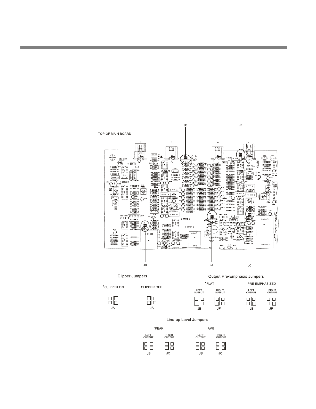
2-16
INSTALLATION ORBAN MODEL 8600
If you are using an Orban 8200ST external AGC:
If the STL uses preemphasis, its input preemphasis filter will probably introduce
overshoots that will increase peak modulation without any increase in average
modulation. We therefore strongly recommend that the STL transmitter’s preemphasis be defeated (freeing the STL from such potential overshoot) and that the 8200ST
be used to provide the necessary preemphasis.
If the STL transmitter’s preemphasis cannot be defeated, then configure the 8200ST
for flat output. In this case average modulation levels of the STL may have to be re-
Figure 2-4: 8200ST Jumper Settings (*Factory Configuration)
Page 77

OPTIMOD-FM DIGITAL INSTALLATION
duced to accommodate the overshoots.
1. Configure the 8200ST’s internal jumpers.
A) Remove all screws holding the 8200ST’s cover in place; then lift it off.
Refer to Figure 2-4 on page 2-16.
2-17
B) Place jumper JA in the C
C) If you have defeated the STL transmitter’s preemphasis, place jumpers JE and
JF in the P
D) If you cannot defeat the STL transmitter’s preemphasis, place jumpers JE and
JF in the F
E) Replace the top cover and then replace all screws snugly. (Be careful not to
strip the threads by fastening the screws too tightly.)
2. Install the 8200ST in the rack. Connect the 8200ST’s audio input and out-
put.
Refer to the 8200ST Operating Manual if you require information about installation, audio input, and audio output connections to the 8200ST.
3. Set 8200ST Output Level with tone.
A) Press the TONE button on the 8200ST.
The TONE lamp should light and the modulation meters should indicate
“0.” If they do not, re-strap jumpers JB and JC to “peak.” (Refer to Figure
2-4 on page 2-16.)
The 8200ST is now producing a 400Hz sine wave at each output. The peak
level of this tone corresponds to 100% modulation.
RE-EMPHASIZED position.
LAT position.
LIPPER ON position.
B) Adjust the 8200ST’s L
ing driven to 100% modulation.
L OUT and R OUT controls are now correctly calibrated to the transmit-
The
ter. If no significant overshoot occurs in the transmitter, the
meter will now give an accurate indication of peak modulation of the
STL.
C) Turn off the tone by pressing the T
If the STL transmitter suffers from bounce or overshoot, you may have to
reduce the
modulation caused by overshoots on certain audio signals.
4. Set controls for normal operation with program material.
The following assumes that a VU meter is used to determine 8200ST line drive
levels with program material.
A) Set controls as follows:
HF LIMITER .... Set to match the preemphasis of the transmission system
L&R Out ............................................................................... do not change
L OUT and R OUT control settings to avoid peak over-
OUT and R OUT controls so that the STL transmitter is be-
MODULATION
ONE button.
Page 78

2-18
INSTALLATION ORBAN MODEL 8600
GATE .................................................................................................... 12:00
RELEASE ............................................................................................... 12:00
VOICE ...................................................................................................... OFF
AGC .......................................................................................................... ON
COUPLE .................................................................................................... ON
B) Feed the 8200ST either with tone at your system reference level (0VU), or with
typical program material at normal levels.
C) Adjust the G
We recommend 8-15 dB gain reduction for most formats.
If the STL uses preemphasis, its input preemphasis network will probably
introduce overshoots that will increase peak modulation without any increase in average modulation. We therefore strongly recommend that
the STL transmitter’s preemphasis be defeated (freeing the STL from such
potential overshoot) and that the 464A be used to provide the necessary
preemphasis.
If the STL transmitter’s preemphasis cannot be defeated, configure the
8200ST for flat output. In this case, average modulation levels of the STL
may have to be reduced to accommodate the overshoots.
AIN REDUCTION control for the desired amount of gain reduction.
Quick Setup
The 8600’s Quick Setup feature provides a guided, systematic procedure for setting
up the 8600. It should be adequate for most users without special or esoteric requirements. Following this section, you can find more detailed information regarding setup outside the Quick Setup screens. Mostly, you will not need this extra information.
Quick Setup configures the 8600 for an analog-FM facility only. If you are setting up
an digital radio facility (HD Radio, DAB/DAB+, etc.), you must use the detailed instructions found after this Quick Setup section.
For the following adjustments, use L
NTER) to select parameters. After you have highlighted the desired parameter on
E
the screen, use the front panel control knob to adjust the parameter settings, as desired.
1. From the pop-up Menu display, Locate to System Setup, then press the
Enter button.
If the pop-up Menu isn’t onscreen, press the control knob in.
2. From the System Setup screen, Locate to the Quick Setup icon, then
press the Enter button.
Quick Setup presents a guided sequence of screens into which you must insert information about your particular requirements.
OCATE (the green joystick, between ESCAPE and
Page 79

OPTIMOD-FM DIGITAL INSTALLATION
Each Quick Setup page is titled in the top right corner (e.g., page 1 is System Setup > Quick Setup 1).
3. Set time and date.
OCATE to the Time & Date screen (System Setup > Quick Setup 2).
A) L
B) Choose Time Format as desired (either 24-hour time or 12-hour AM / PM-style
time).
C) Set hours, minutes, and seconds, in that order, using a 24-hour format for en-
tering hours even if you have set the time format to 12-hour.
Seconds will stop advancing when you set hours and minutes. So set seconds last.
D) Choose the desired date format.
E) Set today’s date.
F) If you want the clock to reset itself automatically to conform to Daylight Sav-
ing Time (Summer Time), use the B
EGINS and ENDS fields to specify when Day-
light Saving Time begins and ends in your area. If you do not wish to use this
feature, leave the B
EGINS and ENDS fields set to Off.
2-19
Note that the clock will set itself automatically if you have set the 8600 to
synchronize to an Internet timeserver. See Synchronizing Optimod to a
Network Time Server in page 2-69.
4. Set preemphasis in regional settings screen.
OCATE to the Regional Settings screen (SYSTEM SETUP > QUICK SETUP 3).
A) L
B) Select the preemphasis (either 75µS or 50µS) used in your country.
Because there is only one field in this screen, you do not have to LOCATE
to the Preemphasis field; it will automatically be active.
There may be a slight time delay between when you move the knob and
when the preemphasis indication changes.
You can change the preemphasis later from the
INPUT/OUTPUT >
UTILITIES screen.
5. Set External AGC mode.
OCATE to Studio Configuration screen (SYSTEM SETUP > QUICK SETUP 4).
A) L
B) Set the External AGC mode.
• Set the field to Y
ES if you have an external AGC (such as an Orban 1100,
1101, 6300, 8200ST OPTIMOD-Studio, Orban 464A Co-Operator, or similar
AGC) installed at your studio feeding the studio-to-transmitter link. This
setting defeats the 8600’s AGC for all presets.
• If you do not have an external AGC installed, set the field to N
ting allows the selected preset to determine the 8600 AGC status.
O; this set-
Page 80

2-20
INSTALLATION ORBAN MODEL 8600
• If you are using an Orban 4000 Transmission Limiter, set field to N
O (so that
the AGC function in the 8600 continues to work). The Orban 4000 is a
transmission system overload protection device; it is normally operated below threshold. It is not designed to perform an AGC or gain-riding function
and it cannot substitute for the AGC function in the 8600.
Most of the processing structures in the 8600 control level with a preliminary AGC (Automatic Gain Control). If you are using a suitable Automatic
Gain Control at the studio, the AGC in the 8600 should be defeated. This
is so that the two AGCs do not “fight” each other and so they do not
simultaneously increase gain, resulting in increased noise.
6. Set input levels.
A) Prepare to adjust the Input Reference Levels.
a) Feed normal Program material to the 8600.
Play program material from your studio, peaking at normal program levels (typically 0VU if your console uses VU meters).
b) LOCATE to the Reference Levels screen (SYSTEM SETUP > QUICK SETUP 5).
The Reference Level screen allows you to match the 8600 to the normal
operating level to be expected at the 8600, so the 8600’s AGC can operate in the range for which it was designed. There are separate settings
for the analog and digital inputs. If you provide both analog and digital
inputs to the 8600, optimum adjustment is achieved when the same
amount of processing is indicated for either analog or digital inputs. This
will allow you to switch between analog and digital inputs without sudden level changes.
B) Using the SET INPUT TO field, set the input to ANALOG.
[Skip this step if you are not using the analog input.]
a) Adjust the A
NALOG REFERENCE LEVEL so that the meter reads an average of
10 dB gain reduction.
[−9 dBu to +13 dBu (VU), or –2 to +20 dBu (PPM)] in 0.5 dB steps
NALOG REFERENCE LEVEL VU and PPM settings track each other with
The A
an offset of 8 dB. This compensates for the typical indications with program material of a VU meter versus the higher indications on a PPM.
If you know the reference VU or PPM level that will be presented to the
8600, set the
ANALOG REFERENCE LEVEL to this level, but please verify it with
the steps shown directly below.
b) If the AGC gain reduction meter averages less than 10 dB gain reduction
(higher on the meter), re-adjust the A
NALOG REFERENCE LEVEL to a lower
level.
c) If the AGC gain reduction meter averages more gain reduction (lower on
the meter), re-adjust the A
This control has no effect on the AES3 digital input.
NALOG REFERENCE LEVEL to a higher level.
C) Using the SET INPUT TO field, set the input to DIGITAL.
Page 81

OPTIMOD-FM DIGITAL INSTALLATION
[Skip this step if you are not using the digital input.]
2-21
a) Adjust the D
IGITAL INPUT REFERENCE so that the meter reads an average of
10 dB gain reduction.
[−30 to –10 dBFS (VU), or –23 to –3 dBFS (PPM)] in 0.5 dB steps.]
IGITAL REFERENCE LEVEL VU and PPM settings track each other with
The D
an offset of 8 dB. This compensates for the typical indications with program material of a VU meter versus the higher indications on a PPM.
If you know the reference VU or PPM level that will be presented to the
8600, set the
DIGITAL REFERENCE LEVEL to this level, but do verify it with the
steps shown directly below.
b) If the AGC gain reduction meter averages less than 10 dB gain reduction
(higher on the meter), re-adjust the D
IGITAL REFERENCE LEVEL to a lower
level.
c) If the AGC gain reduction meter averages more gain reduction (lower on
the meter), re-adjust the D
This control has no effect on the analog inputs.
IGITAL REFERENCE LEVEL to a higher level.
D) Select primary Input Source:
Using the S
ET INPUT TO field, set the input to the source (analog, digital,
or DIG+J17) that you will use for normal programming.
DIG+J17 applies J.17 de-emphasis to the incoming digital signal. It is only
applicable to certain STLs (like NICAM) that use this type of preemphasis
and that have not applied their own de-emphasis prior to their3 AES
outputs.
7. Configure output.
OCATE to the Output Configuration screen (SYSTEM SETUP > QUICK SETUP 6).
A) L
B) Set the A
NALOG OUTPUT PRE / FLAT control to PRE-E (for preemphasis) or FLAT.
[Skip this step if you will not be using the analog output.]
If you will use the analog output to drive a stereo encoder,
vides the best performance because this stereo encoder does not have to
restore the preemphasis. However, if you cannot defeat the preemphasis
in your stereo encoder, or if you will use the analog output for monitor-
ing, set the output F
LAT.
If you are sending the output of the 8600 through a digital link that uses
lossy compression (like MPEG, APT-X, or Dolby), set the output FLAT. Lossy
codecs cannot handle pre-emphasized signals.
C) Set the D
IGITAL OUTPUT #1 PRE / FLAT control to PRE-E (for preemphasis), FLAT,
or PRE-E+J17.
[Skip this step if you will not be using the “AES1” digital output.]
(See the notes immediately above.)
PRE-E pro-
Page 82

2-22
INSTALLATION ORBAN MODEL 8600
PRE-E+J17 applies both FM preemphasis and J.17 preemphasis (in cas-
cade) to the signal and is only used with STLs using J.17 preemphasis
when their own J.17 preemphasis filters are bypassed. These are rare.
D) Set the DIGITAL OUTPUT #1 SAMPLE RATE to 32, 44.1, 48, 88.2, or 96 kHz.
[Skip this step if you will not be using the “AES1” digital output.]
The 8600’s fundamental sample rate is always 64 kHz, but the internal
sample rate converter sets the rate at the 8600’s digital output. This adjustment sets the output sample rate to ensure compatibility with equipment requiring a fixed sample rate.
8. Set output levels.
A) Locate to the Set Output Levels screen (S
YSTEM SETUP > QUICK SETUP 7).
B) You can use either program material or tone to set the output level (and thus,
the on-air modulation). If you want to use tone, set the 400H
TONE
to ON.
Z CALIBRATION
C) Using a modulation monitor or modulation analyzer, adjust the outputs you
are using (analog, digital, composite 1 and composite 2) to make the modulation monitor read 100% modulation (usually ±75 kHz deviation).
D) If you are using program material, make sure that the program material is
loud enough to produce peaks of frequent recurrence that hit the 8600’s peak
limiting system, thereby defining the maximum peak level that the 8600 will
produce. In the U.S., we recommend using 900µs peak weighting on the peak
modulation indicator, as permitted by F.C.C. rules. This will cause the monitor
to ignore very low energy overshoots and will produce the highest peak modulation permitted by law.
In other countries, use a peak-indicating instrument as specified by the
regulatory authority in your country.
If you are required to implement the multiplex power limits specified by
ITU-R 412, you may seldom see peaks hitting ±75 kHz deviation. In this
case, we advise you to set the output level using the 8600’s reference
400Hz tone.
In the United States, F.C.C. Rules permit you to add 0.5% modulation for
every 1% increase in subcarrier injection. For example, if your subcarrier
injection totals 20%, you can set the total modulation to 110% (±82.5
kHz deviation).
The 8600 can reduce audio modulation to compensate for subcarriers.
Once you are finished with Quick Setup, navigate to SYSTEM
NETWORK REMOTE 1 and program the Remote Interface Terminal for
OD. REDUCTION 1 or MOD. REDUCTION 2. Set the amount of modulation re-
M
duction by navigating to INPUT/OUTPUT > COMPOSITE and adjusting the
MOD. RED. 1 and MOD. RED. 2 parameters. When both are active, the mod-
ulation reduction is the sum of their settings. In general, set the modulation reduction to one-half the injection of the associated subcarrier.
For example, if your subcarrier injection totals 20% from two 10% subcarriers, set M
your audio modulation to 90% (100% – 5% – 5%). When you add back
OD. RED. 1 to “5%” and MOD. RED. 2 to 5%. This will reduce
SETUP >
Page 83

OPTIMOD-FM DIGITAL INSTALLATION
the 20% modulation due to the subcarriers, you get the required 110%
total modulation.
OD. REDUCTION function is active as long as signal is applied to its as-
The M
sociated GPI input.
The advantage of using the M
jection stays constant when the audio modulation is reduced. However,
using the M
quires programming and activating at least one 8600 GPI input. If you
have the same subcarrier injection at all times, a more convenient alternative is to set the desired modulation level by using the C
control(s). Then turn up the PILOT LEVEL control (in the INPUT / OUTPUT >
COMPOSITE screen) until the injection equals 9% modulation.
OD. REDUCTION function is slightly inconvenient because it re-
OD. REDUCTION function is that the pilot in-
OMPOSITE LEVEL
9. Choose a factory preset.
OCATE to the Choose Preset screen (SYSTEM SETUP > QUICK SETUP 8).
A) L
2-23
B) Using the L
light a preset corresponding to your format. Press E
OCATE joystick up/down control or turning the control knob, high-
NTER to put the highlight-
ed preset on the air.
Preset names are just suggestions. Some of the most competitive presets
(the “Loud” and “Impact” families) are intentionally not named for formats because these presets can be used in a wide variety of competitive
mass-appeal music formats. Feel free to audition different presets and to
choose the one whose sound you prefer. This preset may have a very different name than the name of your format. This is OK.
You can easily modify a preset with the 8600’s one-knob L
ture. After you have finished with Quick Setup, Navigate to the B
MODIFY screen. If you do not see the LESS-MORE screen immediately, press
and hold the LOCATE joystick to the right or left until you find the screen.
Turning L
cessing artifacts like distortion and unpleasant density. Turning L
MORE down will make the sound cleaner, more open, and easier to listen
to, but will also make it quieter.
ESS-MORE up will produce more loudness but also more pro-
ESS-MORE fea-
ASIC
ESS-
C) Congratulations! You are now on the air with your initial sound. Feel free to
read the material in Section 3 of this manual, which describes the various presets and how you can customize them to an almost unlimited extent.
10. Complete Station ID.
The Station ID is an optional setting that you can provide to associate the 8600
with the station providing the program material (e.g., “KABC”). The Station ID
appears on the Meters screen to the left of the date, and on many other screens,
in the left pane, above the date.
A) Locate to the Station Identifier screen (System Setup > Quick Setup 9).
B) To erase the default Station ID name, use L
press E
NTER.
OCATE to highlight CLEAR, then
C) Enter in your Station ID name.
For each keypad item, Locate to the item and press E
NTER.
Page 84

2-24
INSTALLATION ORBAN MODEL 8600
For upper case letters, first L
OCATE to the SHIFT key and then press ENTER.
D) When finished entering your name, highlight S
AVE and press ENTER.
11. Complete Quick Setup.
A) Locate to the Finished screen (S
B) Press E
SCAPE once to return to the System Setup screen, or twice to display
YSTEM SETUP > QUICK SETUP 10).
the Meters screen. Alternatively, press the control knob to display the pop-up
Menu.
Quick Setup is finished, unless your country is required to meet ITU-R 412-7 requirements (see next step)
Note that Quick Setup only guides you through setting up the processing for the
analog FM output. To set up the HD output, see About the 8600’s HD / Digital Radio
Processing on page 3-71.
12. If you are required to meet the “multiplex power” limitations of ITU-R
412-7 in your country, activate the 8600’s ITU-R 412 controller.
[Skip this step if your country does not enforce ITU-R 412. At the time of this
writing, it is only enforced in certain European countries.]
A) Navigate to the I
NPUT/OUTPUT > UTILITIES screen.
a) Press the control knob to display the pop-up Menu.
b) Turn the knob to highlight I
c) L
OCATE to the INPUT/OUTPUT > UTILITIES screen.
B) Set the M
ULTIPLEX POWER THRESHOLD to “0.0 dB.”
NPUT/OUTPUT and press the knob.
If your transmission system introduces overshoot in the signal path after
the 8600 (including the transmitter), instead set the M
ULTIPLEX POWER
THRESHOLD so that it equals the amount of peak overshoot (in dB) in the
transmission system. If you do not do this, the 8600’s ITU-R 412 controller
will set the average multiplex power too low.
The easiest way to measure system overshoot is to turn the multiplex
power controller off temporarily. Then set the 8600’s output level, using
its built-in 400Hz reference tone, so that the transmitter produces ±75
kHz deviation. Finally, play program material with lots of high frequency
energy and bass transients (like bright rock music with heavy kick drum)
and observe the peak deviation produced by the program material. The
overshoot is the amount (in dB) by which the deviation with program
material exceeds ±75 kHz deviation.
If your country does not enforce ITU-R 412, the MULTIPLEX POWER
THRESHOLD should be set to OFF.
Because the multiplex power controller sometimes uses the output of the
8600’s stereo encoder as its reference, set the C
trol (page 3-43) to O
FF If you are using the 8600’s analog or digital out-
OMPOSITE LIMIT DRIVE con-
put (not its composite output) to drive the transmission system.
Page 85

OPTIMOD-FM DIGITAL INSTALLATION
The total gain reduction of the BS.1770 controller (see step 13 below) and
MPX power controller is split before and after the FM peak limiter such
that the first 3 dB of gain reduction occurs before the peak limiter.
Hence, you can achieve full ±75 kHz deviation when the gain reduction is
between 0 and 3 dB. Any gain reduction greater than 3 dB is applied after the peak limiter, permitting you to achieve more of the “FM limiter
sound” with higher amounts of gain reduction. (Because some of the
gain control is applied after the peak limiter, the peak deviation may be
limited to less than ±75 kHz.)
2-25
See the notes on the Multiplex Power Offset
more information on the multiplex power controller, refer to ITU-R Mul-
tiplex Power Controller on page 3-80.
For “MX” presets or anytime the diversity delay is active, the 8600 computes the multiplex power from the left and right outputs of the audio
processing because there is too much delay to use the output of the stereo encoder. Under these circumstances, the 8600 cannot directly take into account the setting of the C
13. Set up and activate the BS.1770 Safety Limiter in the analog radio pro-
cessing chain (optional)
The BS.1770 safety limiter and meter have been included to allow your Optimod
to comply with government regulations in countries that enforce BS.1770-based
loudness control (per EBU Recommendation R 128) in analog FM transmission.
Unless your country requires this, leave the BS.1770 Safety Limiter off.
The analog-chain BS.1770 safety limiter and meter are calibrated with reference
to 100% modulation with 50µs preemphasis (±75 kHz deviation) per section 5.9
of EBU Tech 3344 (“Practical guidelines for distribution systems in accordance
with EBU R 128”).
The BS.1770 Safety Limiter is usually used in conjunction with the BS.412 Multiplex Power Limiter. The processing chain is configured as follows:
MPX Offset Control → BS.1770 controller (0 to 3dB GR) → Peak Limiter →
BS.1770 controller (>3dB GR) → BS.412 Controller
OMPOSITE LIMIT DRIVE control.
control on page 3-44. For
The MPX
BS.1770/BS.412 chain to prevent excessive amounts of gain reduction. This arrangement allows you to apply as much “FM processor sound” as you want to
the audio. Turn the MPX
limiters harder.
We recommend using as little gain reduction as possible to prevent unnatural
sounding source-dependent loudness variations—a limitation of the BS.1770 algorithm itself, which can over-indicate the loudness of material with substantial
dynamics compression by up to 3 dB compared to subjective impressions by lis-
POWER OFFSET control allows you to reduce the drive level into the
POWER OFFSET control up (closer to 0) to drive the peak
Page 86

2-26
INSTALLATION ORBAN MODEL 8600
1
teners
. We suggest using a maximum of 3 dB gain reduction in the BS.1770 safe-
ty limiter.
A) Navigate to the I
B) Turn the 1770
C) Set the 1770
NPUT/OUTPUT > UTILITIES screen.
SAFETY LIMITER control ON.
LOUDNESS THRESH control to the target loudness specified by your
country’s governing authority. EBU B 128 specifies –23 LUFS.
The BS.1770 Loudness Meter is calibrated in relative units (LU) so that it
indicates “0” when the loudness is equal to the target loudness set by the
1770 LOUDNESS THRESH control. In an overshoot-free transmission system,
a 1 kHz sinewave at –23 LUFS must produce an FM carrier deviation of
±10 kHz without pilot tone. This corresponds to 13.33% modulation
without pilot tone. This calibration includes 50µs transmission preemphasis.
Note for version 2.0.2 software: We have found that with typical pop
music, a –23 LUFS setting typically produces about –5 dB BS.412 MPX
Power and rarely produces ±75 kHz peak carrier deviation. 0dB MPX
power is not reached unless the BS.1770
proximately –17 LUFS. This behavior seems odd (the low modulation level
significantly compromises the received S/N ratio in weak signal areas and
in moving vehicles), so we are unsure if our interpretation of EBU Tech
3344 is correct in this initial release and we welcome any feedback.
Please email Bob Orban at the address shown at
http://www.orban.com/contact/ if you discover an error in our calibration.
THRESHOLD control is set to ap-
D) The calibration of the 1770 LOUDNESS THRESH control is correct if the transmit-
ter’s modulation level was calibrated using your Optimod’s built-in lineup
tone (step 8 on page 2-22). If you turned down the drive level to the FM
transmitter (via the C
OMPOSITE OUT, DO 100%, or AO 100% controls depending
on how you are driving your transmitter) to compensate for overshoots in the
signal path following the Optimod, turn the 1770
LOUDNESS THRESH control up
by the same amount that you turned the output level control down. This will
preserve correct loudness at the receiver.
For example, assume that you turned down the output level control by
2 dB compared to its calibration using your Optimod’s tone generator, so
that a line-up tone that would produce ±75 kHz deviation in an overshoot-free transmission system instead produces ±59.6 kHz deviation to
allow for 2 dB of overshoot with program material. In this case, set the
LOUDNESS THRESH control to –21 LUFS instead of –23 LUFS.
1770
E) If you have not already done so in step 12 on page 2-24, activate the MPX
Power Controller by setting it to some setting other than O
to enable the M
ULTIPLEX POWER OFFSET control.
FF. This is necessary
1
See Begnert, Fabian; Ekman, Håkan; Berg, Jan, “Difference between the EBU R-128
Meter Recommendation and Human Subjective Loudness Perception,” AES Convention Paper 8489, 131
st
AES Convention, (October 2011). This paper states, “These
loudness-equalized signals gave rise to a perceived maximum loudness difference of
2.8 dB.”
Page 87

OPTIMOD-FM DIGITAL INSTALLATION
Using program material typical of your format, adjust the MULTIPLEX
POWER OFFSET control so that the BS.1770 Safety Limiter produces about
3 dB of gain reduction on typical program material. This control is part of
the processing preset, so after you have set the control, save the preset as
a User Preset.
You must adjust the MULTIPLEX POWER OFFSET control for each processing
preset you plan to use and then save each one as a user preset.
The following material provides detailed instructions on how to set up the 8600. If
Quick Setup does not fully address your setup needs or if you wish to customize your
system beyond those provided with Quick Setup, then you may need the additional
information in the sections below. You will need this information if you are setting
up a digital radio facility. However, for most users, this material is only for reference,
because Quick Setup has enabled them to set up the 8600 correctly.
Analog and Digital I/O Setup
2-27
For the following I/O calibration parameters, use the LOCATE joystick to highlight in-
put/output parameters. When the desired parameter is highlighted, turn the front
panel control knob to adjust the parameter settings as desired.
Analog and digital parameters appear on the same screen. If you are not using a
given input or output, ignore the parameters associated with it.
1. Specify processing preemphasis.
Navigate to the I
control to select the preemphasis (either 75µS or 50µS) used in your country
2. Temporarily set the External AGC mode to “No.”
Navigate to the I
If you are using an external AGC, you will restore this setting to YES after
the setup procedure is complete.
3. Adjust input selector.
A) Navigate back to the I
B) Set the I
4. Adjust Clip Level control.
NPUT to ANALOG.
NPUT/OUTPUT > UTILITIES screen. Use the PROCESS PREEMPHASIS
NPUT/OUTPUT > UTILITIES screen and set EXTERNAL AGC to NO.
NPUT/OUTPUT > INPUT screen.
[0 dBu to +27 dBu] in 0.5 dB steps
This step matches the level at which the 8600’s A-D (Analog-to-Digital) converter
clips to the absolute maximum peak level that your installation supplies to the
8600’s analog input.
Page 88

2-28
INSTALLATION ORBAN MODEL 8600
This setup maximizes the 8600’s signal-to-noise ratio. If the clip level is set too
low, the 8600’s analog-to-digital converters will overload and distort on program
peaks. If the clip level is set too high, the signal-to-noise ratio will suffer. Use care
and attention in setting this adjustment.
We have found that the single most common reason for distorted sound on-air in
other Orban digital processors is maladjustment of the C
that the A/D converter is clipping and distorting. This will always be clearly indi-
cated by the I
If you are adjusting the 8600 during normal programming and cannot interrupt
or distort the program to play program material from your studio at a much
higher level than normal, follow the directions to:
• Calibrate while on air with normal programming: step (A) on page 2-28.
If you are able to interrupt or distort normal programming, you can achieve calibration that is more precise. Follow the directions to:
• Calibrate with unprocessed audio: step (B), page 2-28, or
• Calibrate with a Studio Level Control System that has a built-in 100% Calibra-
tion Tone, such as the Orban 6300, 8200ST-Studio Level Controller or 4000
Transmission Limiter: step (C), page 2-29, or
NPUT meters’ going into the red part of their scale.
LIP LEVEL control, such
• Calibrate with an Orban 464A Co-Operator: step (D), page 2-29, or
• Calibrate with an Orban 1100 or 1101 OPTIMOD-PC
as appropriate.
Note that in this step, you are calibrating to the absolute peak level; this is quite
different from the maximum peak indication of the studio meters.
A) Calibrate with program material and normal programming levels.
[Skip this step if you are calibrating in another manner.]
a) Adjust the C
on the input meters.
Observe the meters on the 8600 screen for a long period; be sure to observe live announcer voice. If this setting is misadjusted, distortion will result.
0 dB indicates input clipping on the 8600. These meters should never
peak as high as 0 dB with program material; always leave a safety margin
of headroom.
B) Calibrate with program material and worst-case programming levels (best
method):
[Skip this step if you are calibrating in another manner.]
a) Play program material from your studio at a much higher level than nor-
mal—turn the faders up all the way!
LIP LEVEL so that program peaks indicate approximately –15 dB
This will usually produce the highest peak level output that your system
can produce.
Page 89

OPTIMOD-FM DIGITAL INSTALLATION
METER CAL
0
set to preemphasis of your STL; if no preemphasis, set to 25µs
OUTPUT ATTEN
0
INPUT ATTEN
10
GATE THRESH
0
RELEASE TIME
0
REL SHAPE
SOFT
LEVEL
OFF
COMPR
OFF
HF LIMIT
OPERATE
SYSTEM
OPERATE
POWER
ON
MODE
DUAL
b) Adjust the 8600’s CLIP LEVEL so that on program peaks the input meters in-
dicate no more than approximately –2 dB.
0 dB indicates input clipping on the 8600. These meters should never
peak as high as 0 dB with program material; always leave a safety margin
of headroom.
C) Calibrate with a Studio Level Control System that has a built-in 100% Calibra-
tion Tone, such as the Orban 6300 Optimod-DAB, 8200ST-Studio Level Controller or 4000 Transmission Limiter:
[Skip this step if you are calibrating in another manner.]
a) Turn on the Studio Level Control System’s 100% Calibration Tone.
On the Orban 4000 Transmission Limiter, press both of the 4000’s front
panel TONE buttons.
b) Adjust the output level of the Studio Level Control System for 100% modu-
lation of the STL.
2-29
c) Adjust the 8600’s C
LIP LEVEL to indicate –2 dB on the input meters.
D) Calibrate with an Orban 464A Co-Operator:
[Skip this step if you are calibrating in another manner.]
The 464A does not have a built-in 100% tone. The easiest way to set the
8600 input peak clipping level is to temporarily re-adjust the 464A to
produce clipped waveforms on program material to give a clear indication of peak clipping level.
a) Record the normal operating settings of the 464A.
b) Set both channels of the 464A controls as follows:
HF LIMIT PREEMPHASIS
c) Play program material from your studio.
d) Adjust the 464A’s METER
464A’s PEAK
OUTPUT LEVEL meter just illuminates on program peaks.
e) Adjust the 464A’s OUTPUT
lation.
CAL controls so that the 0 dB segment on the
ATTEN controls to drive the STL to 100% modu-
Page 90

2-30
INSTALLATION ORBAN MODEL 8600
f) Adjust the 8600’s C
mately –2 dB on the meter on the screen.
g) Return the 464A to the normal settings.
E) Calibrate with an Orban 1100 or 1101/1101e Optimod-PC:
[Skip this step if you are calibrating in another manner.]
Refer to the Optimod-PC manual for instructions on setting it up as an
external AGC. You will usually use one of its three AGC presets.
Optimod-PC does not have a built-in 100% tone generator. The easiest
way to set the 8600 input peak clipping level is to recall a “loud” preset
in Optimod-PC that will produce substantial amounts of gain reduction in
Optimod-PC’s look-ahead limiter. This will produce frequent peaks at the
maximum peak level at OPTIMOD-PC’s output.
a) If you have customized your normal AGC preset in Optimod-PC, save it as a
User Preset.
b) Apply program material at normal level to Optimod-PC’s input.
LIP LEVEL so that the program peaks indicate approxi-
c) Recall the IMPACT preset and verify that the Optimod-PC L
indicate substantial gain reduction.
d) Adjust the 8600’s C
mately –2 dB on the meter on the screen.
e) Recall your regular AGC preset in Optimod-PC.
5. Adjust the Analog Input’s Reference Level.
[−9 dBu to +13 dBu (VU), or –2 to +20 dBu (PPM)] in 0.5 dB steps]
EFERENCE LEVEL VU and PPM (Peak) settings track each other with an offset
The R
of 8 dB. This compensates for the typical indications with program material of a
VU meter versus the higher indications on a PPM.
This step sets the center of the 8600’s gain reduction range to the level to which
your studio operators peak their program material on the studio meters. This ensures that the 8600’s processing presets will operate in their preferred range.
You may adjust this level with a standard reference / line-up level tone from your
studio or with program material.
Note that in this step, you are calibrating to the normal indication of the studio
meters; this is quite different from the actual peak level.
If you know the reference VU or PPM level that the 8600 will receive, set the
EFERENCE LEVEL to this level, but do verify it with the steps shown directly be-
R
low.
LIP LEVEL so that the program peaks indicate approxi-
IMITER meters
A) From the pop-up Menu, select the P
B) Highlight the
C) Press the E
ROCK-MEDIUM preset.
NTER button to select the preset.
RESETS screen.
Page 91

OPTIMOD-FM DIGITAL INSTALLATION
D) Calibrate using Tone.
[Skip this step if you are using program material to calibrate the 8600 to
your standard studio level. Skip to step (E).]
2-31
a) Verify E
XTERNAL AGC is set to NO.
Refer to step 1 on page 2-27 above.
b) Feed a tone at your reference level to the 8600
• If you are not using an external AGC, feed a tone through your con-
sole at normal program levels (typically 0VU if your console uses VU
meters).
• If you are using an Orban 4000 Transmission Limiter, press its two
TEST buttons. Feed a tone through your console at the level to which
you normally peak program material (typically 0VU if your console uses VU meters).
• If you are using a Studio Level Controller that performs an AGC func-
tion, such as an Orban 8200ST OPTIMOD-Studio or 464A, adjust it for
normal operation.
c) Adjust the REFERENCE LEVEL to make the 8600’s AGC meters indicate 10 dB
gain reduction.
d) When finished, reset E
setting prior to setting R
XTERNAL AGC to YES, if required (e.g., if that was its
EFERENCE LEVEL).
e) Skip to step 6.
E) Calibrate using Program.
[Skip this step if you are using tone to calibrate the 8600 to your standard
studio level—see step (D) above.]
a) Verify E
XTERNAL AGC is set to NO.
Refer to step 1 on page 2-27 above.
b) Feed normal Program material to the 8600
Play program material from your studio, peaking at the level to which
you normally peak program material (typically 0VU if your console uses
VU meters).
c) Adjust the REFERENCE LEVEL to make the 8600’s AGC meters indicate an av-
erage of 10 dB gain reduction when the console’s VU or PPM is peaking at
its normal level.
• If the AGC gain reduction meter averages less than 10 dB gain reduc-
tion (higher on the meter), set the R
• If the AGC gain reduction meter averages more gain reduction (lower
on the meter), set the REFERENCE LEVEL to a higher level.
EFERENCE LEVEL to a lower level.
d) When finished, reset EXTERNAL AGC to YES, if required (e.g., if that was its
setting prior to setting the R
EFERENCE LEVEL).
Page 92

2-32
INSTALLATION ORBAN MODEL 8600
6. Adjust the Analog Input’s Right Channel Balance.
[Skip this step if the channels are already satisfactorily balanced.]
[−3 dB to +3 dB] on right channel only, 0.1 dB steps
Adjust R
IGHT BALANCE to achieve correct left/right channel balance.
This is not a balance control like those found in consumer audio products.
This control changes gain of the right channel only. Use this control if the
right analog input to the 8600 is not at exactly the same level as the left
input. Be certain that the imbalance is not from a certain program
source, but only through distribution between the console output and
8600 input. This is best accomplished by playing program material that is
known to be monophonic, or by setting the mixing console into mono
mode (if available).
7. Adjust the Digital Input Reference Level and Right Balance controls.
If you will be using the digital input, set the input to D
and 6 above using the R
IGITAL section.
D
EFERENCE LEVEL and RIGHT BALANCE controls for the
IGITAL and repeat steps 5
8. Activate or Defeat the “Multipath Mitigator” Left/Right Skew Corrector.
See “Multipath Mitigator” Left/Right Phase Skew Correction on page 3-8.
The Phase Corrector controls are found in the active Processing Preset. Because
the Phase Corrector adds about 250 ms of delay to the audio path, if you do not
wish to use it, we recommend defeating it in S
YSTEM > UTILITIES via the PHASE
CORRECT DEFEAT control. If you defeat it, this will override the PHASE CORRECTOR
control in the active Processing Preset.
9. Set response to an invalid or missing digital input signal. (optional)
Refer to step 17 on page 2-40
10. Set up and activate the BS.1770 Safety Limiter in the digital radio pro-
cessing chain (optional)
The BS.1770 Safety Limiter prevents the BS.1770-3 integrated loudness in the dig-
ital radio processing chain from exceeding a value set by the BS.1770
LOUDNESS
CONTROL THRESHOLD control. If your country requires that the integrated loud-
ness of your digital radio broadcast to be constrained according to the BS.1770-3
loudness measurement algorithm, execute the steps below. If your country does
not require this, leave the BS.1770 Safety Limiter off.
A) Navigate to the I
B) Set the BS.1770
NPUT/OUTPUT > HD RADIO screen.
LOUDNESS CONTROL THRESHOLD control to be equal to the tar-
get integrated loudness of your broadcast as specified by the regulatory authority in your country.
C) Using the O
N radio button, turn the BS.1770 SAFETY LIMITER control ON.
Page 93

OPTIMOD-FM DIGITAL INSTALLATION
D) To use the BS.1770 Safety Limiter, you must assign the output source of one of
the Digital Outputs to HD. We suggest using Digital Output 1 to drive the digital radio transmitter.
To facilitate error-free loudness calibration through your transmission
system, activating the BS.1770 Safety Limiter changes the behavior of the
Digital Output 100% PEAK LEVEL control. Normally, changing the setting
of this control changes both the loudness and peak level of the signal
appearing at the Digital Output driving your digital radio transmitter.
However, when the BS.1770 Safety Limiter is turned ON, the Digital Output becomes the "Loudness Reference Output" and the Digital Output
PEAK LEVEL control sets only the peak level, not the loudness. In this
100%
case, the output loudness is always calibrated correctly with respect to
0 dBFS.
(Note: If both Digital Output 1 and Digital Output 2 are sourced from
“HD,” then Digital Output 2 becomes the “Loudness Reference Output”
instead of Digital Output 1.)
For example, setting the Digital Output 1 100% PEAK LEVEL control to
–3 dBFS always constrains the maximum peak level appearing at Digital
Output 1 to –3 dBFS, but changing the setting of the Digital Output 1
PEAK LEVEL control does not change loudness. This is because when
100%
the BS.1770 Safety Limiter is turned ON, a second “hidden” gain control
is inserted before the input of the peak limiter. The gain set by the “hidden” control complements the setting of the Digital Output 1 100%
LEVEL control. For example, when the Digital Output 1 100% PEAK LEVEL
control is set to –3 dBFS, the “hidden” control adds 3 dB of gain before
the peak limiters to compensate for the 3 dB of loss that the 100%
LEVEL control introduces after the peak limiters. Unless the peak limiters
produce gain reduction, this arrangement keeps the overall gain constant
from the input of the peak limiter to the Digital Output.
If the peak limiters produce enough gain reduction to reduce loudness
audibly, this gain reduction will cause the output loudness to be lower
than the setting of the BS.1770
never occur with BS.1770 reference levels normally used in digital radio
(–18 LUFS) and digital television (–23 LUFS or –24 LUFS) because with
these reference levels, any peak limiting that occurs will be too brief to
audibly affect loudness.
LOUDNESS CONTROL THRESHOLD. This will
PEAK
PEAK
2-33
Unless the 100% PEAK LEVEL control is set to 0 dBFS, this arrangement
causes the output loudness to change when you toggle the BS.1770
SAFETY LIMITER control ON and OFF. In our example, the loudness will decrease by 3 dB when you set the BS.1770
SAFETY LIMITER to OFF.
E) After you have chosen a Processing Preset and adjusted it to your taste (step
20 on page 2-41, you must set the preset’s HD
FINAL LIMITER DRIVE to create the
appropriate amount of gain reduction in the BS.1770 Safety Limiter. Then
save the result as a User Preset. We recommend allowing the BS.1770 Safety
Limiter to produce no more than 3 dB of gain reduction.
11. Set output and configuration level.
A) Navigate to the I
NPUT/OUTPUT > OUTPUT1 screen.
Page 94

2-34
INSTALLATION ORBAN MODEL 8600
You can use either program material or tone to set your output level
(and thus, your on-air modulation). If you want to use tone, turn the
400Hz calibration tone on.
B) Set the A
NALOG OUT SOURCE to FM or FM+DELAY, depending on whether you
need to apply diversity delay to that source. See Diversity Delay on page 2-74.
Be aware that this setting can be toggled between FM and FM+DELAY by
several means in addition to the ANALOG OUT SOURCE control in the
INPUT/OUTPUT > OUTPUT1 screen. These additional means include the 8600’s
GPI inputs (page 2-60), its serial ports (page 2-48), its Ethernet input (via
8600 PC Remote or a terminal program), and its clock-based automation
(page 2-42).
C) Set the ANALOG OUTPUT PRE / FLAT control to PRE-E (for preemphasis) or FLAT.
[Skip this step if you will not be using the analog output.]
If you will use the analog output to drive a stereo encoder,
PRE-E pro-
vides the best performance because this stereo encoder does not have to
restore the preemphasis. However, if you cannot defeat the preemphasis
in your stereo encoder or if you will use the analog output for monitor-
ing, set the output F
LAT.
If you are sending the analog output of the 8600 through a digital link
that uses lossy compression (like MPEG, APT-X, or Dolby), set the output
LAT. Lossy codecs cannot handle pre-emphasized signals.
F
[Skip steps (D) through (I) if you will not be using the”AES1” digital
output. Note that both the “AES1” and “AES2” digital outputs have
identical functionality, so you could use either one in the steps below.]
D) Set the AES1
ONITOR.
M
•
• HD is not available in 8600FM units.
OUT SOURCE control to the desired source: FM, FM+DELAY, HD, or
In most facilities, you will set it to FM.
E) Set the AES1 PRE/FLAT control to PRE-E (for preemphasis), FLAT, or PRE-E+J17.
• See the notes immediately above.
• P
RE-E+J17 applies both FM preemphasis and J.17 preemphasis (in cas-
cade) to the signal and is only used with STLs using J.17 preemphasis
when their own J.17 preemphasis filters are bypassed. These are rare.
F) Set the AES1 output SAMP RATE (sample rate).
[32], [44.1], [48], [88.2], or [96], in kHz
The 8600’s base sample rate is always 64 kHz, but the internal sample rate
converter sets the rate at the 8600’s digital output. This adjustment sets
the 8600’s output sample rate to ensure compatibility with equipment
requiring a fixed sample rate.
G) Adjust the AES1 SR
SYNC control.
[Internal / Sync In / Input]
Page 95

OPTIMOD-FM DIGITAL INSTALLATION
You can lock the sample rate of each of the 8600’s AES3 outputs to the
sample rate of a reference AES3 signal that is applied to the AES3 input
or to an AES11 signal that is applied to the SYNC input.
If you wish to operate the two AES3 outputs at different sample rates,
only one output can be synced to the signal at the SYNC input. However,
in this case the other output could be synced to the signal appearing at
the digital input.
2-35
The selections for each of the two AES outputs are I
NTERNAL, SYNC IN, and
INPUT. INPUT sets a given AES3 output sample rate and synchronization to
the same sample rate present at the 8600’s AES3 (audio) input. Likewise,
YNC IN uses the AES11 sync input’s sample rate and synchronization as
S
the source. I
8600’s internal clock and uses the S
NTERNAL synchronizes the given AES3 output rate to the
AMP RATE setting to determine its out-
put sample rate.
For a given AES3 output, the output sample-rate selector (“S
has no effect in the I
NPUT and SYNC IN modes unless sync is lost. Then the
AMP RATE”)
output reverts to internal sync at the sample rate that is preset by the
sample-rate selector for that output. Otherwise, the output sample rate
follows the sample rate present at the selected input regardless of the
setting of the output sample rate selector.
If no signal is provided to the 8600 digital input or S
NTERNAL and select the desired output sample rate.
to I
MPX hardware provides a sync reference input (labeled R
YNC IN, set SR SYNC
EF IN) on a fe-
male BNC jack at the end of the breakout cable that connects to the digital composite connector. It accepts a 1x 5V p-p squarewave wordclock
signal at 32, 44.1, 48, 88.2, or 96 kHz, or a 10 MHz sinewave or
squarewave signal, 0.5 to 5 V peak. 10 MHz is a common output frequency produced by GPS and rubidium frequency standards. You can configure the 8600 to lock its 19 kHz pilot tone and output sample frequency to
this input.
When a valid reference signal is applied to this input, it locks the Optimod’s Internal DSP clock to this input, so if a given AES3 L/R output’s sync
source is set to Internal, the sample frequency at that output will be
locked to this reference signal. This will also lock the 192 kHz sample rate
of the digital composite output and the pilot tone frequency appearing
at both the analog and digital composite outputs to the reference signal.
See Digital Composite Outputs on p. 2-11, Digitized Subcarrier Inputs on
p. 2-11, and Wordclock/10 MHz Sync Reference Input on p. 2-11
H) Set the desired output W
RD LENGTH (word length).
[14], [16], [18], [20], or [24] bits
The largest valid word length in the 8600 is 24 bits. The 8600 can also
truncate its output word length to 20, 18, 16 or 14 bits. The 8600 can also
add dither and you should set it to do so if the input material is insufficiently dithered for these lower word lengths. (See the next step.)
I) Adjust D
ITHER to IN or OUT, as desired.
Page 96

2-36
INSTALLATION ORBAN MODEL 8600
[In] or [Out]
It is wise to leave this control set to I
When set to I
N, the 8600 adds “high-pass” dither before any truncation
N.
of the output word. The amount of dither automatically tracks the set-
ting of the W
ORD LENGTH control. This is first-order noise-shaped dither
that reduces added noise in the midrange considerably by comparison to
white PDF dither. However, unlike extreme noise shaping, it adds a maximum of 3 dB of excess total noise power when compared to white PDF
dither. Thus, it is a good compromise between white PDF dither and extreme noise shaping.
J) If you are using the AES2 output, repeat steps (D) through (I) for this output.
Its controls are located on the I
NPUT/OUTPUT > OUTPUT2 screen.
K) If you are using the Ratings Encoder Loop-through feature, perform the fol-
lowing steps (see Connecting a Ratings Encoder on page 2-8):
a) Set the AES2
OUT SOURCE control to AGC>RATINGS or LIMIT>RATINGS.
b) Connect your Optimod’s AES2 output to the input of the ratings encoder.
c) Connect the ratings encoder’s output to your Optimod’s S
Depending on whether you choose AGC>RATINGS or LIMIT>RATINGS, the
SYNC input is repurposed automatically to drive the input of the FM/HD
split point or your Optimod’s stereo encoder. AGC applies a controlled
audio level to the encoder and allows you to use one ratings encoder for
both FM and HD; L
ings encoder but requires two ratings encoders if you are transmitting
HD.
IMIT applies the highest possible audio level to the rat-
YNC INPUT.
d) Set the AES2 output SAMP RATE to 48 kHz.
e) Set the AES2 output W
RD LENGTH to 24-bit.
• In Ratings Encoder Loop-through mode, you cannot use your Optimod’s
S
YNC INPUT to receive a sync reference signal. You can still lock your Opti-
mod’s output sample rate to a signal applied to its AES3 input.
• The Ratings Encoder Loop-through mode has a standard fallback strategy:
To prevent an audio mute, your Optimod will automatically bypass the
loop-though if there is no valid AES3 signal at your Optimod’s Sync Input.
When this happens ratings encoding does not occur, so warnings will flash
on both the Optimod’s front panel and in PC Remote (if previously connected to your Optimod). Nevertheless, we recommend monitoring the
presence of valid ratings encoding via the monitor supplied by the ratings
provider.
L) Using a modulation monitor or modulation analyzer, adjust the outputs you
are using (analog and/or digital) to make the modulation monitor read 100%
modulation (usually ±75 kHz deviation).
If you are using program material, make sure that the program material
is loud enough to produce peaks of frequent recurrence that hit the
8600’s peak limiting system, thereby defining the maximum peak level
Page 97

OPTIMOD-FM DIGITAL INSTALLATION
that the 8600 will produce. In the U.S., we recommend using 900µs peak
weighting on the peak modulation indicator, as permitted by F.C.C. rules.
This will cause the monitor to ignore very low energy overshoots and will
result in the highest peak modulation permitted by law.
In other countries, use a peak-indicating instrument as specified by the
regulatory authority in your country.
If you are required to implement the average modulation limits specified
by ITU-R 412-7, you may seldom see peaks hitting ±75 kHz deviation. In
this case, we advise you to set the output level using the 8600’s reference
400Hz tone.
In the United States, F.C.C. Rules permit you to add 0.5% modulation for
every 1% increase in subcarrier injection. For example, if your subcarrier
injection totals 20%, you can set the total modulation to 110% (±82.5
kHz deviation). This implies that you must set the 8600’s composite output level for the equivalent of 90% modulation, not counting the subcarriers. (90% + 20% = 110%.) This will mean that pilot injection will be
about 8% modulation instead of the desired 9%. From the Input/output
> Composite screen, adjust
9% modulation (±6.75 kHz deviation). This will ordinarily require you to
set the
PILOT LEVEL parameter to “10%.”
PILOT LEVEL control as necessary to produce
2-37
12. Set preemphasis mode of Output meters (optional).
When the M
UTLEVEL, the 8600’s Output meters normally indicates the peak output level
FMO
ETER SELECT switch (in INPUT/OUTPUT > HD DIGITAL RADIO) is set to
of the FM analog processing, which is always pre-emphasized. If you wish to ap-
ply de-emphasis before these meters, navigate to I
the FM
The default is P
OUTPUT METER to DE-EMPH.
RE-EMP.
NPUT/OUTPUT > UTILITIES and set
13. Set the polarity of the analog FM processing (optional).
In HD Radio installations, this command is useful when switching the 8600 between transmitters if the transmitters’ exciters produce opposite FM modulation
polarities when driven by identical digital audio input signals. This setting affects
any output emitting the analog FM processed signal, including the composite
output.
A) Navigate to the I
B) Set the FM
NPUT/OUTPUT > UTILITES screen.
POLARITY control to POSITIVE or NEGATIVE as appropriate for your
transmitter.
14. Configure composite outputs.
[Skip this step if you are not using the composite baseband outputs.]
A) Navigate to the I
NPUT/OUTPUT > COMPOSITE screen.
B) Adjust the composite level at the composite output(s) you are using so that
the FM carrier is modulated to 100% on modulation peaks. Alternately, you
can use tone.
Page 98

2-38
INSTALLATION ORBAN MODEL 8600
If you are using subcarriers, this screen allows you to specify the amount
by which the 8600 automatically reduces main and stereo subchannel
modulation to accommodate the subcarrier within the modulation limits
specified by the governing authority.
See step (8.C) on page 2-22 for a more detailed discussion.
C) Set the M
ODULATION MODE to STEREO
In addition to STEREO. the MODULATION MODE control also allows you to set
the modulation mode to MONO-L, MONO-R, and MONO-SUM (mono modulation sourced from the left input, right input, or sum of the left and
right inputs). For testing, it also offers a P
a stereo waveform with no pilot tone.
SSB will operate the stereo encoder in its experimental single-sideband
mode (see SSB Stereo Encoder Operation on page 3-11) and will activate
a peak modulation controller to prevent composite modulation from exceeding 100% when this controller is used in conjunction with the 8600’s
composite limiter. We recommend setting the Composite Limit Drive control to 0dB for SSB operation. This control is part of the active processing
preset and can be accessed from either the Intermediate Control or Advanced Control screen.
ILOT OFF mode, which transmits
D) Set the PILOT LEVEL to 9% modulation.
If you have to reduce the setting of the COMPOSITE LEVEL control to accommodate overshoots in the transmission path following the 8600 (including the transmitter), you may have to increase the setting of the
ILOT LEVEL so that the transmitted pilot is still at 9% modulation.
P
E) Set the DIVERSITY DELAY control to IN or OUT as appropriate for your installa-
tion.
Digital Composite Setup
In MPX hardware, there is one AES3 digital composite output at 192 kHz sample
rate. Its sample rate is locked to the 8600’s internal clock unless you have applied
a valid clock signal to the R
EF INPUT BNC on the Digital Composite daughter
board, in which case it will be locked to this clock, as will the stereo pilot tone
frequency. See Wordclock/10 MHz Sync Reference Input on page 1-11.
F) If you will be using subcarriers, connect your subcarrier generators to the dig-
itized SCA inputs, located on the breakout cable.
G) Navigate to the I
H) Adjust the SCA
NPUT/OUTPUT > COMPOSITE2 screen.
INPUT 1 and SCA INPUT 2 controls to produce the desired
amount of subcarrier injection.
Refer to step 8 on page 2-22 for more information on setting modulation
levels.
I) Adjust the C
OMPOSITE OUT control to achieve the desired modulation level.
In 8600 PC Remote, this control is located in I/O SETUP > DIGITAL ENCODER.
Page 99

OPTIMOD-FM DIGITAL INSTALLATION
15. Set up a low-delay headphone monitoring system (optional).
If you are using an “MX” preset and/or using the diversity delay, it is impossible
for talent to monitor the signal off-air while speaking because the delay is too
large. To provide a talent headphone feed, you can configure any of the 8600’s
left/right outputs (analog, AES1, and AES2) to receive the output of a special version of the multiband compressor (without look-ahead). The input/output delay
is approximately 3-8 milliseconds (depending on the setting of AGC
CROSSOVER
TYPE) and should be comfortable for talent. See the discussion in Monitoring on
Loudspeakers and Headphones on page 1-26.
Note that the Multipath Mitigator adds about 250 ms of delay to the audio path, including the monitor output, so you must defeat it in Setup if
you wish to use the low-delay monitor output.
To configure any output for Low-Delay Monitoring:
2-39
A) Locate to the I
outputs. Locate to the I
NPUT/OUTPUT > OUTPUT1 screen to configure the analog or AES1
NPUT/OUTPUT > OUTPUT2 screen to configure the AES2
output.
B) Choose O
UT SOURCE > MONITOR.
C) Set the preemphasis control to F
ing.
CAUTION: The low-delay output has no peak limiting and is therefore
not suited for driving a transmitter. If you use the low delay output, you
must drive your transmitter with a digital output or with the composite
output.
If you need a low-delay output that can drive a transmitter, configure the
8600’s outputs for O
presets. See Ultra-Low-Latency Five-Band on page 3-20.
If you use the low-delay output to drive both your studio monitor speakers and talent headphones (which may be necessary if your console has
only one monitor input for both), we recommend connecting a loss-ofcarrier alarm to one of the 8600’s GPI inputs and programming this input
to mute the monitor output in the event that carrier is lost. This simulates
normal “off air” monitor functionality and immediately alerts the staff if
the transmitter goes off the air unexpectedly.
You can program any GPI terminal for Monitor Mute functionality from
YSTEM SETUP > NETWORK/REMOTE 1 (the REMOTE screen). The OUT SOURCE
S
parameter located in the I
to MONITOR to make the Monitor Mute feature work.
UT FEEDS: TRANSMITTER and use one of the 8600’s UL
NPUT/OUTPUT > OUTPUT1 screen needs to be set
LAT for the output you are using for monitor-
16. Defeat the final clipper (optional).
If you are using the 8600 to drive a network with protection audio processors
(like Orban’s Optimod-FM 2300 or 5500) at each transmitter, you may wish to defeat the 8600’s final clipper to prevent double clipping, which can unnecessarily
increase distortion on-air. To do this:
A) Put a non-MX preset on air. (Clipper defeat is not supported in MX presets.)
B) Locate to the I
NPUT/OUTPUT > UTILITIES screen.
Page 100

2-40
INSTALLATION ORBAN MODEL 8600
C) Set F
INAL CLIP DEFEAT to DEFEAT.
This will also defeat the overshoot compensator.
Note that defeating the final clipper and overshoot compensator will increase peak output levels, possibly to the point where the 8600’s output
amplifier and/or digital output clips. It is wise to customize any presets
you are using by reducing the F
INAL CLIP DRIVE and OSHOOT COMP DRIVE
controls to their minimum values. This will greatly reduce the probability
of inadvertently clipping the 8600’s output.
Unless defeated, the 8600’s composite limiter will continue to control the
composite output level. However, you should not use the composite output when the 8600’s final clipper is defeated because this will remove the
advantages of the distortion cancellation in the 8600’s final clipper. (The
composite limiter does not cancel distortion.)
17. Program Silence Sense (optional)
You can program the 8600 to switch automatically from its digital input to its
analog inputs if the I
NPUT SOURCE is set to DIGITAL and the signal at the digital in-
put falls silent. Conversely, you can also program the 8600 to switch automatical-
ly from its analog inputs to its digital input if the I
NPUT SOURCE is set to ANALOG
and the signal at the analog input falls silent.
There are two silence detectors, one for the analog input and one for the
digital input. The silence sense parameters apply to both simultaneously.
Both detectors are available to drive the 8600’s tally outputs, and either
silence detector can be used to instigate automatic input switching. (See
Tally Output Programming on page 2-62.)
Silence sense will be activated if either channel falls silent, protecting
against “loss-of-one-stereo-channel” faults.
If silence is detected at both the analog and digital inputs (as in the case
of a studio operational fault), automatic switching will not occur.
When an active signal is restored to the preferred input, the 8600 will automatically switch back to that input.
When the digital input is in the silence detect fallback state, the unit and
PC will show the input as being D
silence detect fallback, they will indicate ANASILENCE.
IGSILENCE; when the analog input is in
A) Navigate to INPUT/OUTPUT > SILENCE DETECT.
B) Set the S
ILENCE THRESHOLD to the level below which the 8600 will interpret
the input as being silent.
This setting is with respect to the current analog reference level and digital reference level.
C) Set the SILENCE DELAY to the amount of time that the input must be below
ILENCE THRESHOLD before the 8600 automatically switches to the analog
the S
input.
D) Set the A
from the digital to analog input when silence is detected. Set the control to
N
NALOG FALLBACK to YES if you wish the 8600 to automatically switch
O to defeat automatic switching.
 Loading...