

Page 1

Operating Manual
OPTIMOD-FM
8200
Digital Audio Processor
®
Page 2
IMPORTANT NOTE: Refer to the unit ’s rear panel for your Model #.
Model Number: Description:
8200/U3S OPTIMOD-FM 8200 DIGITAL with three DSP cards, Stereo Encoder,
Protection Structure, Two-band Purist Structure, Two-band Normal
Structure, Multi-band Processing Structure, set to 115V (for 90-130V
operation), switchable to 50µs or 75µs.
8200/E3S OPTIMOD-FM 8200 DIGITAL with three DSP cards, Stereo Encoder,
Protection Structure, Two-band Purist Structure, Two-band Normal
Structure, Multi-band Processing Structure, set to 230V, (for 180-260V
operation), switchable to 50µs or 75µs.
OPTIONS A VAILABLE:
Model Number: Description:
CIT25 Composite Isolation Transformer.
8200D/32 Digital I/O Card, 32kHz
8200 PC Remote Control Software for IBM PC compatible computers
MANUAL:
Part Number: Description:
95100-301-01 8200 Manual (includes 8200 PC Manual)
CAUTION: TO REDUCE THE RISK OF ELECTRICAL S HO CK , DO NO T REMOVE COVER (OR BACK).
NO USER SERV I CE A B LE PARTS I NS I DE . REFER SERVICING TO QUA LIFIED SERVICE P E RS ONNEL.
WARNING: TO REDUCE THE RISK OF FIRE OR ELECTRICAL SHO CK,
DO NOT EXPOSE THIS APPLIANCE TO RAIN OR MOISTURE.
This symbol, wherever i t appears , This symbol, wherever i t appears ,
alerts you to the presence of unins ul ate d alerts you to important operat ing and
dangerous voltage inside the enc los ure — volt age maintenance instruc tions i n the ac c ompany in g
that may be suff ic i ent t o constitute a risk of shock. literature. Read the manual.
Page 3

All the safety and operating instructions should be read before the appliance is operated.
Retain Instructions:
The safety and operation instructions should be retained for future reference.
Heed Warnings:
All warnings on the appliance and in the operating instructions should be adhered to.
Follow Instructions:
All operation and user instructions should be followed.
Water and Moisture:
The appliance should not be used near water (e.g., near a bathtub, washbowl, kitchen sink, laundry tub, in a wet
basement, or near a swimming pool, etc.).
Ventilation:
The appliance should be situated so that its location or position does not interfere with its proper ventilation. For example, the
appliance should not be situated on a bed, sofa, rug, or similar surface that may block the ventilation openings; or, placed in a built-in
installation, such as a bookcase or cabinet that may impede the flow of air through the ventilation openings.
Heat:
The appliance should be situated away from heat sources such as radiators, heat registers, stoves, or other appliances (including
amplifiers) that produce heat.
Power Sources:
The appliance should be connected to a power supply only of the type described in the operating instructions or as
marked on the appliance.
Grounding or Polarization:
Precautions should be taken so that the grounding or polarization means of an applianceis not defeated.
Power-Cord Protection:
Power-supply cords should be routed so that they are not likely to be walked on or pinched by items placed
upon or against them,paying particular attention to cords at plugs,convenience receptacles, and the point where they exit from the appliance.
Cleaning:
The appliance should be cleaned only as recommended by the manufacturer.
Non-Use Periods:
The power cord of the appliance should be unplugged from the outlet when left unused for a long period of time.
Object and Liquid Entry:
Care should be taken so that objects do not fall and liquids are not spilled into the enclosure through
openings.
Damage Requiring Service:
The appliance should be serviced by qualified service personnel when:
The power supply cord or the plug has been damaged; or
Objects have fallen, or liquid has been spilled into the appliance; or
The appliance has been exposed to rain; or
The appliance does not appear to operate normally or exhibits a marked change in performance; or
The appliance has been dropped, or the enclosure damaged.
Servicing:
The user should not attempt to service the appliance beyond that described in the operating instructions. All other servicing
should be referred to qualified service personnel.
The Appliance should be used only with a cart or stand that is recommended by the manufacturer.
Safety Instruct ions (European)
Notice For U.K. Customers If Your Unit Is Equipped With A Power Cord.
WARNING: THIS APPLIANCE MUST BE EARTHED.
The cores in the mains lead are coloured in accordance with the following code:
GREEN and YELLOW - Earth BLUE - Neutral BROWN - Live
As colours of the cores in the mains lead of this appliance may not correspond with the coloured markings identifying the terminals in your
plug, proceed as follows:
The core which is coloured green and yellow must be connected to the terminal in the plug marked with the letter E, or with the earth symbol,
( ), or coloured green, or green and yellow.
The core which is coloured blue must be connected to the terminal marked N or coloured black.
The core which is coloured brown must be connected to the terminal marked L or coloured red.
The power cord is terminated in a CEE7/7 plug (Continental Europe). The green/yellow wi re i s connected direc tl y to the unit ’s chassis. If
you need to change the plug and if you are qualified to do so, refer to the table below.
WARNING: If the ground is defeated, certain f ault conditions in the unit or in the sys tem to which it is conne cted ca n result in full line
voltage between chassis and eart h ground. Severe injury or de ath can then re sult if the chassis and earth ground are touched simultaneously.
AC Power Cord Color Coding
IMPORTANT SAFETY INSTRUCTIONS
CONDUCTOR
WIRE COLOR
Normal Alt
L LIVE BROWN BLACK
NEUTRAL BLUE WHITE
EARTH GND GREEN-YELLOW GREEN
N
E
Page 4
Safety Instruc tions ( G erm an)
Gerät nur an der am Leistungsschild vermerkten Spannung und Stromart betreiben.
Sicherungen nur durch solche, gleicher Stromstärke und gleichen Abschaltverhaltens ersetzen. Sicherungen nie überbrücken.
Jedwede Beschädigung des Netzkabels vermeiden. Netzkabel nicht knicken oder quetschen. Beim Abziehen des Netzkabels den
Stecker und nicht das Kabel enfassen. Beschädigte Netzkabel sofort auswechseln.
Gerät und Netzkabel keinen übertriebenen mechanischen Beaspruchungen aussetzen.
Um Berührung gefährlicher elektrischer Spannungen zu vermeiden, darf das Gerät nicht geöffnet werden. Im Fall von Betriebsstörun-
gen darf das Gerät nur Von befugten Servicestellen instandgesetzt werden. Im Gerät befinden sich keine, durch den Benutzer
reparierbare Teile.
Zur Vermeidung von elektrischen Schlägen und Feuer ist das Gerät vor Nässe zu schützen. Eindringen von Feuchtigkeit und
Flüssigkeiten in das Gerät vermeiden.
Bei Betriebsstörungen bzw. nach Eindringen von Flüssigkeiten oder anderen Gegenständen, das Gerät sofort vom Netz trennen und
eine qualifizierte Servicestelle kontaktieren.
Safety Instruct ions (Fr ench)
On sassurera toujours que la tension et la nature du courant utilisé correspondent bien à ceux indiqués sur la plaque de lappareil.
Nutiliser que des fusibles de même intensité et du même principe de mise hors circuit que les fusibles dorigine. Ne jamais shunter les
fusibles.
Eviter tout ce qui risque dendommager le câble seceur. On ne devra ni le plier, ni laplatir. Lorsquon débranche lappareil, tirer la fiche
et non le cäble. Si un cäble est endommagé, le remplacer immédiatement.
Ne jamais exposer lappareil ou le cäble ä une contrainte mécanique excessive.
Pour éviter tout contact averc une tension électrique dangereuse, on noouvrira jamais lappareil. En cas de dysfonctionnement,
lappareil ne peut être réparé que dans un atelier autorisé. Aucun élément de cet appareil ne peut être réparé par lutilisateur.
Pour éviter les risques de décharge électrique et dincendie, protéger lappareil de lhumidité. Eviter toute pénétration dhumidité ou fr
liquide dans lappareil.
En cas de dysfonctionnement ou si un liquide ou toutautre objet apénétré dans lappareil couper aussitôt lappareil de son alimentation
et sadresser à un point de service aprésvente autorisé.
Safety Instructions ( Spanish)
Hacer funcionar el aparato sólo con la tensión y clase de corriente señaladas en la placa indicadora de características.
Reemplazar los fusibles sólo por otros de la misma intensidad de corriente y sistema de desconexión. No poner nunca los fusibles en
puente.
Proteger el cable de alimentación contra toda clase de daños. No doblar o apretar el cable. Al desenchufar, asir el enchufe y no el
cable. Sustituir inmediatamente cables dañados.
No someter el aparato y el cable de alimentación a esfuerzo mecánico excesivo.
Para evitar el contacto con tensiones eléctricaspeligrosas, el aparato no debe abrirse. En caso de producirse fallosde funcionamiento,
debe ser reparado sólo por talleres de servicio autorizados. Enel aparato no se encuentra ninguna pieza que pudiera ser reparada por
el usuario.
Para evitar descargas eléctricas e incendios, el aparato debe protegerse contra la humedad, impidiendo que penetren ésta o líquidos
en el mismo.
En caso de producirse fallas de funcionamiento como consecuencia de la penetración de líquidos u otros objetos en el aparato, hay
que desconectarlo inmediatamente de la red y ponerse en contacto con un taller de servicio autorizado.
Safety Instructions (Italian)
Far funzionare lapparecchio solo con la tensione e il tipo di corrente indicati sulla targa riportante i dati sulle prestazioni.
Sostituire i dispositivi di protezione (valvole,fusibili ecc.) solo con dispositivi aventi lo stesso amperaggio e lo stesso comportamento di
interruzione. Non cavallottare mai i dispositivi di protezione.
Evitare qualsiasi danno al cavo di collegamento alla rete. Non piegare o schiacciare il cavo. Per staccare il cavo, tirare la presa e mai
il cavo. Sostituire subito i cavi danneggiati.
Non esporre lapparecchio e il cavo ad esagerate sollecitazioni meccaniche.
Per evitare il contatto con le tensioni elettriche pericolose, lapparecchio non deve venir aperto. In caso di anomalie di funzionamento
lapparecchio deve venir riparato soloda centri di servizio autorizzati. Nellapparecchionon si trovano partiche possano essereriparate
dallutente.
Per evitare scosse elettriche o incendi, lapparecchio va protetto dallumidità. Evitare che umidità o liquidi entrino nellapparecchio.
In caso di anomalie di funzionamento rispettivamente dopo la penetrazione di liquidi o oggetti nellapparecchio, staccare immedi-
atamente lapparecchio dalla rete e contattare un centro di servizio qualificato.
Page 5
PLEASE READ THIS FIRST!
Manual
The Operating Manual contains instructions to verify the proper operation of this unit and initialization of certain options.
You will find these operations are most conveniently performed on the bench before you install the unit in the rack.
Please review the Manual, especially the installation section, before unpacking the unit.
Trial Period Precautions
If your unit has been provided on a trial basis:
You should observe the following precautions to avoid reconditioning charges in case you later wish to return the unit to
your dealer.
Note the packing technique and save all packing materials. It is not wise to ship in other than the factory carton. (Replace-
ments cost $35.00).
(1) Avoid scratching the paint or plating. Set the unit on soft, clean surfaces.
(2) Do not cut the grounding pin from the line cord.
(3) Use care and proper tools in removing and tightening screws to avoid burring the heads.
(4) Use the nylon-washered rack screws supplied, if possible, to avoid damaging the panel. Support the unit when
tightening the screws so that the threads do not scrape the paint inside the slotted holes.
Packing
When you pack the unit for shipping:
Tighten all screws on any barrier strip(s) so the screws do not fall out from vibration.
Wrap the unit in its original plastic bag to avoid abrading the paint.
Seal the inner and outer cartons with tape.
If you are returning the unit permanently (for credit), be sure to enclose:
•
The Manual(s)
•
The Registration Card
•
The Line Cord
•
All Miscellaneous Hardware (including the Rack Screws)
•
The Extender Card
•
The COAX Connecting Cable
Your dealer may charge you for any missing items.
If you are returning a unit for repair, do not enclose any of the above items.
Further advice on proper packing and shipping is included in Section 5: Troubleshooting.
Trouble
If you have problems with installation or operation:
(1) Check everything you have done so far against the instructions in the Manual. The information contained therein is
based on our years of experience with OPTIMOD and broadcast stations.
(2) Check the other sections of the Manual (consult the Table of Contents and Index) to see if there might be some
suggestions regarding your problem.
(3) After reading the section on Factory Assistance, you may call Orban Customer Service for advice during normal
California business hours. The number is (1) 510/351-3500.
®
Page 6

MAINTAINING 8200 SECURITY
Important: Ensure 8200 se curity by making it standard polic y for each 8200 user to manually
re-enable loc kout when finished with normal operation.
If your 8200 uses security pascodes and TIMEOUT TO AUTO LOCK is OFF (as set in the
SET
PASCODE
screen), the last s ucce ssfu l pas code e ntry de fines th e cur re nt secur ity le vel. U ntil locko ut
is re-enabled , subs equent us er s with a low er se curity level will ha ve acc ess to mor e func tion s than
they should.
Therefore, we recommend that each user re-enable lockout mode when finished with normal
operation. R e-en abling lo ckou t ens ur es that ea ch us er is a llowed to enter a p ascode to hav e acc ess
to the correct amount of functions for which their pascode was previously assigned.
If a previous user does for ge t to re- ena bl e l oc kout , sim pl y com pl e te the fo ll owi ng ste ps:
If the
IDLE G/R screen does not appear, press ESC repeatedly until you see it.
Hold down the ESC button, while pressing HELP button.
With 8200 lockout now re-enabled, enter a valid pascode and continue with normal operation.
®
Page 7

Manual Addendum
8200 Version 3.0 Upgrade
For OPTIMOD-FM 8200 Digital
8200 Version 3.0 Manual Addendum
New Format Presets
Insert the following page, titled “New Format Presets In Version 3.00,” into
your 8200 Operation Manual, in Section 3, directly after the blue-tabbed
“About Processing Structures” page, at page 3-9.
There are 21 new format-specific presets, each named for a programming
format. There are two Urban/Rap presets, for instance, that add bottom-end
slam to the sound. Three new Rock presets add punch and sizzle while Adult
Contemporary and Country presets balance warmth and clarity, with up-front
vocals that stand out. There are also presets for Pop, Classical, Instrumental,
Jazz, Folk/Traditional, News, and Sports. There are even two Oldies presets
that ensure consistent sound balance with material from different eras.
Programmed by Bob Orban and Greg Ogonowski, each preset has full
LESS-MORE capability.
Multi-Band Controls
Insert the following “New Multi-Band Features For Version 3.00” pages into
your 8200 Operation Manual, in Section 3, at the end of the discussion on
“The Multi-Band Structure,” directly preceding the red-tabbed “Screen
Displays” page.
New controls include: High Frequency Coupling, Multi-Band Output Mix
controls, Bass Clip Threshold, and Phase Rotator In/Out. The range for the
existing Final Clip Drive has also been extended.
D-O Status Enable?
[Yes] or [No]
For 8200s equipped with the 8200 D/SRC, the 8200's controls now include a
switch that allows you to defeat Orban's special implementation of AES/EBU
status bits which are used to control Orban 8208 and 8218 Stereo Encoders.
This special implementation may be defeated to accommodate certain digital
STLs that misinterpret these status bits.
Beginning with V 1.20 software and revision 3.0 of the 8200D/SRC Digital
I/O board, the 8200 set the emphasis bits in the AES/EBU status bits (byte 0,
bits 2 through 4) accord ing to an Or ban p rop rietary standar d that extends the
AES/EBU official definition. The Orban standard allows the 8200 to
automatically set the 8218 (and 8208) Stereo Encoder's emphasis/deemphasis to complement the 8200's emphasis/de-emphasis.
Page 8

I-2
MANUAL ADDENDUM Orban
Byte 0 Bits 2-4 AES/EBU Definition 8200 Implementation 8218 Response
000 not indicated not indicated applies FM pre-emphasis
001 undefined undefined doesn't alter emphasis
010 undefined undefined doesn't alter emphasis
011 undefined undefined doesn't alter emphasis
100 no emphasis no emphasis applies FM pre-emphasis
101 undefined J.17+FM pre-e* applies J.17 de-emphasis
110 50/15µs FM pre-e* doesn't alter emphasis
111 J.17 J.17 applies J.17 de-emphasis
and FM pre-emphasis
* FM pre-emphasis is 50 or 75µs
Since the implementation of the Orban standard, some digital STLs were
released that misinterpret these status bits. Some respond to the AES/EBU
emphasis bits (110) by applying an EIAJ (50/15uS) shelving de-emphasis.
This will cause an audible (10.5 dB) loss of high frequencies. Version 3.00
software allows the user to enable- or disable the Orban implementation of
status bits. When disabled, the 8200 sends status bits identifying that
emphasis is “not indicated,” which ensures that the affected digital STLs will
not inappropriately apply EIAJ de-emphasis.
When these digital STLs are used in combination with an 8200 and 8218 (or
8208), DO STATUS ENABLE must be set to No, and the 8218 (or 8208),
cannot utilize the “AES determines emphasis” feature.
PC Security Enable
[On] or [Off]
The OPTIMOD 8200 with software Version 3.00 or higher, can be
controlled with a computer utilizing RS-232 and the Orban supplied 8200PC
software for Microsoft Windows, or through binary commands.
The Orban 8200PC software offers full access to all 8200 features, while the
binary communications method can only recall presets.
When set to On (default), this control allows remote control of the 8200
through RS-232 communications, only with the Orban supplied 8200PC
software for Microsoft Windows. Access to the 8200 is the same as under
Version 1.2x.
When set to Off, this mode disables all password protection entirely. PC
access using binary commands is allowed for recalling presets only.
Complete control by 8200PC is still allowed, however password protection is
Page 9

OPTIMOD-FM 8200 V3.00 UPGRADE MANUAL ADDENDUM
disabled. Please note that in this mode, unauthorized access is possible, so
take measures to insure that a secure link is used to the 8200. Concurrent
8200PC and binary communications method is not possible.
The binary communications method is intended to be used primarily by
programmers for third-party software development. Orban Customer Service
will supply a developer's white paper upon request. We cannot, however,
provide any technical support for third-party software.
New Format Presets In Version 3.00
The 21 named format presets in Version 3.00 are entirely new. They exploit new Version
3.00 features, including the OUTPUT MIX controls for the 5-Band Limiter and the
HIGH FREQUENCY COUPLING control. They apply appropriate amounts of BASS,
PRESENCE, and BRILLIANCE equalization.
Of these 21 presets, five are duplicates because we felt that they were appropriate for
more than one format. So there are actually 16 distinct and different presets. Each preset
has full
presets from which they were taken and the nominal
LESS-MORE
Capability. The table below shows the presets, including the source
LESS-MORE
setting of each preset.
I-3
Many of the presets come in several “flavors,” like “dense,” “medium,” and “open.”
These refer to the density produced by the processing. “Open” uses SLOW multi-band
release time, “Medium” uses MEDIUM-SLOW release, and “Dense” uses MEDIUMFAST. FAST release is only used in the NEWS/TALK and SPORTS presets.
Important!
control to trade off loudness against processing artifacts and side effects.
Once you have used LESS-MORE, save your edited preset as a USER
PRESET.
Do not be afraid to experiment with presets other than the ones named for your format if
you think these other presets have a more appropriate sound. Also, if you want to finetune the frequency balance of the programming, feel free to enter FULL CONTROL and
make small changes to the BASS, PRESENCE, and BRILLIANCE controls. Remember
to do this after you have decided on a
have edited a preset using FULL CONTROL,
that edited preset. (Of course,
want to go back to it. There is no way you can erase or otherwise damage the factory
presets. So feel free to experiment.)
These presets are only suggestions. Try using the LESS-MORE
LESS-MORE
LESS-MORE
is still available for the unedited preset if you
setting that's right for you. Once you
LESS-MORE
is no longer available for
Page 10

I-4
MANUAL ADDENDUM Orban
## PRESET NAME SOURCE PRESET NORMAL
LESS-MORE
____ __
FB GENERAL-MEDIUM ADLT CONTEMP-MED 5.0
FC GENERAL-OPEN ADLT CONTMP-OPEN 5.0
FD URBAN/RAP-DENSE URBAN/RAP-DENSE 7.0
FE URBAN/RAP-MEDIUM URBAN/RAP-MEDIUM 7.0
FF ROCK-DENSE ROCK-DENSE 7.0
FG ROCK-MEDIUM ROCK-MEDIUM 7.0
FH ROCK-OPEN ROCK-OPEN 7.0
FI ADLT CONTEMP-MED ADLT CONTEMP-MED 5.0
FJ ADLT CONTMP-OPEN ADLT CONTMP-OPEN 5.0
FK COUNTRY-MEDIUM ADLT CONTEMP-MED 5.0
FL COUNTRY-OPEN ADLT CONTMP-OPEN 5.0
FM POP-DENSE POP-DENSE 5.0
FN POP-MEDIUM POP-MEDIUM 5.0
FO POP-OPEN POP-OPEN 5.0
FP JAZZ JAZZ 5.0
FQ INSTRUMENTAL JAZZ 5.0
FR OLDIES-DENSE OLDIES-DENSE 7.0
FS OLDIES-OPEN OLDIES-OPEN 7.0
FT FOLK/TRADITIONAL POP-MEDIUM 5.0
FU NEWS/TALK N EWS/TALK 5.0
FV SPORTS SPORTS 5.0
Page 11

OPTIMOD-FM 8200 V3.00 UPGRADE MANUAL ADDENDUM
I-5
ROCK:
(although not as exaggerated as the URBAN/RAP presets). There is enough presence
energy to ensure that vocals stand out. A modest amount of HIGH FREQUENCY
COUPLING allows reasonable amounts of automatic HF equalization (to correct dull
program material), while still preventing exaggerated frequency balances and excessive
HF density. These presets are appropriate for general rock and contemporary
programming. For Contemporary Hit Radio (CHR) we recommend the DENSE or
MEDIUM versions. For Album-Oriented Rock (AOR) use ROCK-MEDIUM or OPEN,
although you might prefer the more conservative Adult Contemporary presets here.
URBAN/RAP:
more bass. They use the 3-pole (18dB/octave) shape on the bass equalizer. They are
appropriate for Urban, Rap, Black, R&B, Dance and other similar formats.
ADLT CONTEMP:
and POP. They have a gentle bass and treble lift, along with enough presence energy to
help vocals to stand out. This preset is also used for COUNTRY, and is a useful
candidate for AOR formats.
POP:
substantial HIGH FREQUENCY COUPLING to ensure that the high frequencie s do not
become dense. This is an ideal preset for formats designed primarily for women listeners
(who, by and large, dislike hyped treble) or for any preset designed for long time-spentlistening formats because of its open, clean sound, which leads to very low listener
fatigue. Because of its conservative nature, this preset is also used for the
FOLK/TRADITIONAL preset.
The ROCK presets are designed for a bright high end and punchy low end
The URBAN/RAP presets are similar to the ROCK presets, but with
The Adult Contemporary presets are a compromise between ROCK
POP is a more conservative preset designed for a mellow, open high end. There is
OLDIES:
less. This allows the preset to do substantially more automatic equalization than ROCK,
making recordings of different eras more uniform. OLDIES-OPEN might be a useful
alternative to FOLK/TRADITIONAL if the recordings being played are very
inconsistent in frequency balance.
JAZZ:
play mostly instrumental music. It has a relatively mellow high end and produces very
low listening fatigue.
NEWS/TALK:
FAST 5 Band Release Time setting, so it can quickly perform automatic equalization of
substandard program material, including telephone. It is very useful for creating a
uniform, intelligible sound from widely varying source material, particularly source
material that is “hot from the field” with uncontrolled quality.
SPORTS:
GATE THRESHOLD is higher. This recognizes that most sports programming has very
low signal-to-noise ratio due to crowd noise and other on-field sounds, so the preset does
not pump this up as the NEWS/TALK preset would tend to do.
OLDIES is similar to ROCK except HIGH FREQUENCY COUPLING is
JAZZ is quite similar to POP, and is specifically tailored toward stations that
This preset is quite different from the others above. It is based on the
Similar to NEWS/TALK except the AGC RELEASE TIME is slower and the
Page 12

I-6
MANUAL ADDENDUM Orban
New Multi-Band Features For Version 3.00
High Frequency Coupling Control (Band 3&4 Coupling)
High Frequency Coupling couples a certain percentage of the Band 3 gain control signal
into Bands 4 and 5. This forces Bands 4 and 5 to follow the gain reduction in Band 3 to a
user-adjustable extent. Because Band 3 has a slower release time than Bands 4 and 5,
this results in a more open high end. It also limits the amount of dynamic HF boost that
the processing can produce.
Even with the control at 100%, Bands 4 and 5 are still active and will produce further
gain reduction if this is necessary to prevent distortion. So in this mode they are acting as
a high frequency limiter.
Multi-Band Mix Controls (Band 1-5 Out Mix dB)
All of the equalization described so far occurs
advantage of this is that the multi-band limiter protects you against overloads or program
material with unusual spectral balance, which might otherwise combine with your
equalization curve to cause unpleasant distortion or coloration. In particular, it protects
the final clipper from being overdriven.
However, the
limiter tends to fight equalization settings that you made with the various equalizer
controls, reducing their effect. We have therefore provided a mix control with a ±3dB
range at the
These act as fixed equalizer controls because no gain reduction occurs after them. They
determine the overall target spectral balance of the processing when the multi-band
limiter exhibits substantial amounts of gain reduction. In popular music formats this is
almost always the case.
Please note that these controls are
limiter and multi-band clippers were tuned at great length to ensure that under virtually
no circumstances would program material come along to cause unpleasant clipping
distortion in the following clippers. By adjusting the multi-band mix controls, you upset
this carefully tuned relationship. Therefore, program material can come along that causes
unexpected (and sometimes very nasty-sounding) distortion because the final clippers are
being overdriven. This will occur if the program material in question has a significant
part of its energy concentrated in a frequency band that is being boosted.
downside
output
is that the “automatic equalization” effect of the multi-band
of each limiter in the five-band limiter.
very risky
. The thresholds of OPTIMOD-FM's 5-band
before
the multi-band limiter. The
In general, it is safe to turn a given output mix control
without danger of introducing distortion. However, you will lose loudness. If you turn an
output mix control up (+0.5 to +3dB range), you should listen at great length to a wide
variety of program material to make sure that nothing falls apart due to excessive
down
(in the 0 to –3dB range)
Page 13

OPTIMOD-FM 8200 V3.00 UPGRADE MANUAL ADDENDUM
clipping distortion. If it does, you will need to back off the control in question and/or
back off the
If you turn up the control for Band 1 (below 100 Hz), you may wish to turn down the
Bass Clip Thrsh dB
between the bass multi-band clipper and the final clipper.
Final Clip
control.
control by an equal amount. This will preserve the relationship
Bass Clip Threshold Control (Bass Clip Thrsh dB)
The 8200 uses Orban's patented multi-band distortion-cancelling clipper system to
achieve a low peak-to-average ratio without creating audible distortion due to clipping.
The bass clipper is part of this system. It is embedded in the multi-band crossover so that
harmonics created by clipping are rolled off by part of the crossover filters. The
threshold of this clipper is ordinarily set between 4dB and 6dB below the threshold of
the final clipper in the processing chain, depending on the setting of the
control in the parent preset upon which you are basing your full control adjustments.
This provides headroom for contributions from the other four bands, so that bass
transients don't smash against the final clipper and “shut it down,” momentarily blocking
any other program material and causing a sound similar to very hard pumping. The bass
clipper also protects against overt intermodulation distortion between the bass and higher
frequency program material.
LESS-MORE
I-7
Some 8200 users feel that the bass clipper unnecessarily reduces bass punch at its factory
settings. To accommodate these users, Version 3.00 software makes the threshold of the
bass clipper a user-adjustable control. The range (with reference to the final clip
threshold) is 0 to –6dB. As you raise the threshold of the clipper you will get more bass
but also more distortion and pumping. Be careful when setting this control; do not adjust
it casually. Listen to program material with heavy bass combined with spectrally sparse
midrange material (like a singer) and listen for IM distortion induced by the bass'
pushing the midrange into the final clippers. In general, unless you have a very good
reason to set the control elsewhere, we recommend leaving it at the factory settings,
which were determined as a result of exhaustive listening tests with many types of
critical program material.
Phase Rotator In/Out
The multi-band limiter receives the output of a three-pole phase rotation circuit. This has
a flat frequency response but a phase response that is nonlinear with frequency. Its
purpose is to make voice waveforms symmetrical, which minimizes clipping distortion
and makes voice (particularly live voice from microphone feeds) sound cleaner.
The downside of the phase rotator is that it subtly reduces the clarity and definition of
music. While this is unlikely to be heard on the vast majority of consumer radios, many
people listening with audiophile-quality gear will be able to perceive it. We therefore
have provided the ability to bypass this circuit, leaving only the phase rotation intrinsic
to the crossover topology in the multi-band limiter. This residual phase rotation is
Page 14

I-8
MANUAL ADDENDUM Orban
approximately 25% of the total phase rotation that occurs when the three-pole phase
rotator is active.
When you bypass the phase rotator, many voices sound audibly harsher because more
clipping occurs. This can be particularly problematical if you are processing heavily for
loudness. If you notice increased harshness on voice, we recommend that you use
external phase rotation (three cascaded poles, each tuned to 200Hz) in your live
microphone chain and in your production studio mic chain. If this is impractical, we
recommend leaving the 8200's built-in phase rotator active because we find the increased
voice distortion caused by leaving it off substantially more objectionable than the slight
loss of clarity that results when it is active.
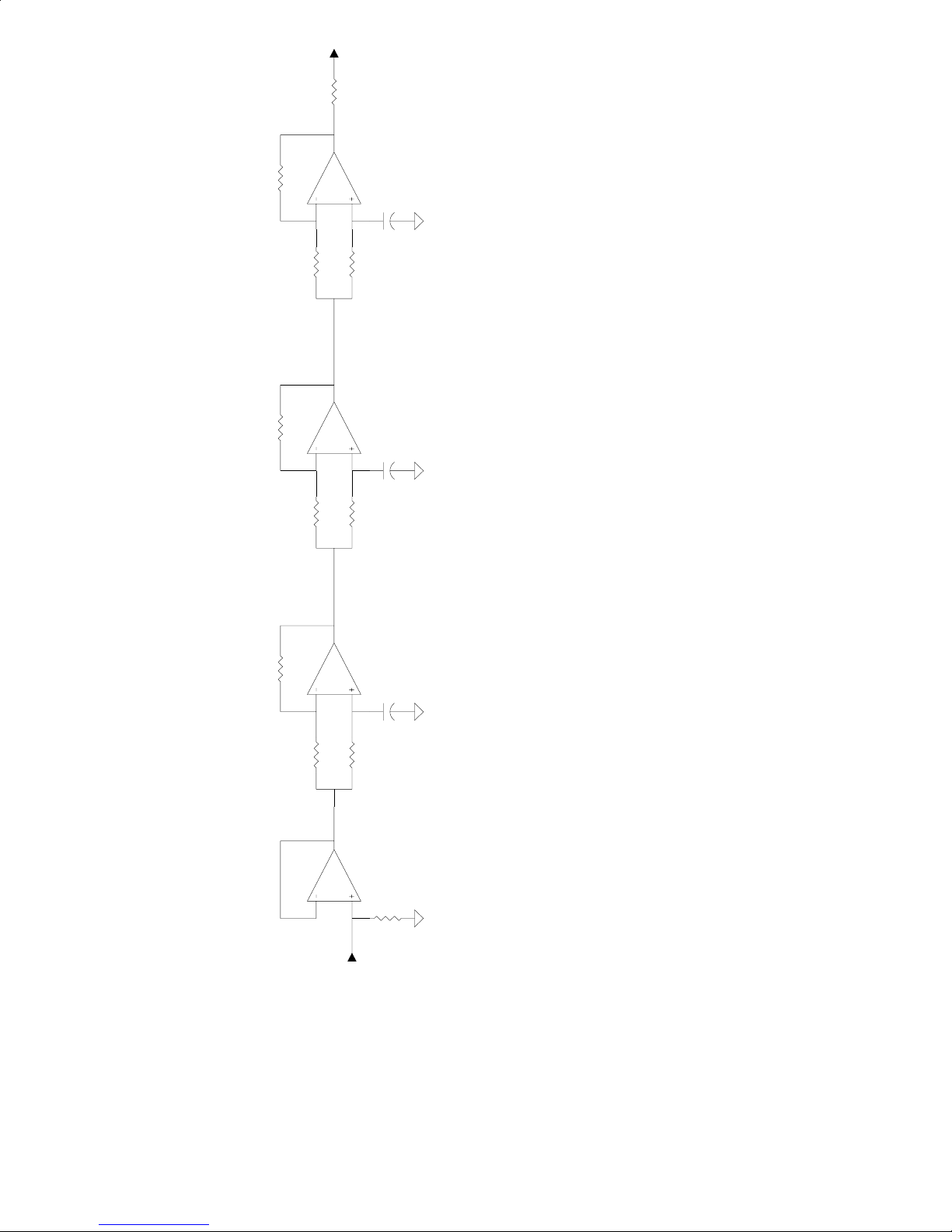
Refer to the “Phase Rotator For Microphone Channel” diagram, on the following page.
Page 15
OUTPUT
OPTIMOD-FM 8200 V3.00 UPGRADE MANUAL ADDENDUM
10K 1%
10K 1%
1K 5%
10K 1%
10K 1%
1/4 TL074
0.01uF 10%
82K 5%
1/4 TL074
0.01uF 10%
82K 5%
50V
50V
I-9
10K 1%
10K 1%
1/4 TL074
1/4 TL074
INPUT
0.01uF 10%
82K 5%
82K 5%
50V
Figure 1: Phase Rotator for Microphone Channel
If you substitute a high-speed amplifier, layout and power supply bypassing become more critical.
Many audio opamps could be substituted for the TL074, like a pair of NE5532s.
Bypass (+) and (−) Power Leads of TL074 to Ground with 0.1µF 50V monolithic ceramic capacitors.
Operate from +15V and −15V DC power.
Notes: Unity Gain, Line Level.
Page 16

I-10
MANUAL ADDENDUM Orban
Final Clip Drive Control
Version 3.00 extends the range of the
end of its range. This means that you can turn down the clipping by 3dB by comparison
to earlier versions of 8200 software. The purpose of this extension is to allow users in
ITU countries to comply with the requirements of ITU-R Recommendation BS.412-7 if
they are required to do so by the regulatory authority in their country.
Based on measurements with a wide variety of program material using the RundfunkBetriebstechnik, GMBH Hubmess System MPX-EBENE (a modulation analyzer), we
have developed the following formula for ensuring compliance. First, you must start with
one of the basic 2-Band or 5-Band factory presets with
then edit the preset (using
following settings:
Preset LESS-MORE Final Clip Drive
DA 5B SLOW 1.0 –1.5
DB 5B-MEDIUM SLOW 1.0 –1.5
DC 5B-MEDIUM FAST 1.0 –3.0
DD 5B-FAST 1.0 –2.5
FULL CONTROL
FINAL CLIP DRIVE
LESS-MORE
) to set the
control by 3dB at the lower
at 1.0. You must
FINAL CLIP DRIVE
to the
CA 2B-NOR PROCESSED 1.0 –1.5
To ensure that you meet the requirements, do not increase the settings of these controls
beyond the settings provided in
MULTI-BAND DRIVE
Note:
The BB (Purist Classical) and BA (Purist Processed) presets will comply with a
CLIPPING setting of –2 or lower. There is no need to reset the
control when using these presets.
The Protection Limiter Structure will not comply and cannot be adjusted to do so.
However, you can use the BB (Purist Classical) preset instead and set its
control to –2.
If you want to use any of the new presets in Version 3.00, you should follow a similar
formula. Set them for
1.5, except for “dense” presets (
CLIP DRIVE
presets using this formula and therefore cannot guarantee compliance, we believe that
compliance is nevertheless very likely.
= –2.5). While we have not specifically measured all of the Version 3.00
.
LESS-MORE
LESS-MORE
= 1.0. Then edit the
FINAL CLIP DRIVE
= 1.0:
RELEASE TIME, CLIPPING
FINAL CLIP DRIVE
CLIPPING
FINAL CLIP DRIVE
= –3.0) and News or Sports (
control for –
, and
FINAL
Page 17

OPTIMOD-FM 8200 V3.00 UPGRADE MANUAL ADDENDUM
8200 Software History
Version 3.00
•
Replaces the original factory “format” presets FB - FO with new format presets
FB- FV.
•
Adds new Multi-Band Control: High Frequency Coupling.
•
Removes EBS Test Mode.
Version 2.00
Multi-Band Controls
•
New controls include: Multi-Band Output Mix controls, Bass Clip
Threshold, and Phase Rotator In/Out. The range for the existing Final Clip
Drive has also been extended.
I-11
D-O Status Enable?
•
[Yes] or [No]
For 8200s equipped with the 8200 D/SRC, the 8200's controls now include a
switch that allows you to defeat Orban's special implementation of AES/EBU
status bits which are used to control Orban 8208 and 8218 Stereo Encoders.
This special implementation may be defeated to accommodate certain digital
STLs that misinterpret these status bits.
PC Security Enable
•
[On] or [Off]
When set to Off, password security is disabled, allowing access to 8200 via
remote PC, utilizing custom-developed software, and limited to recalling
presets only. When set to On, 8200 functions the same as under Version
1.2x, with full password security.
Version 1.20
•
8200PC Remote Control Software for Windows™
•
TIME TO SCREEN SAVER default setting is now 1:00 HRS. Removed Off
setting.
•
AGC IDLE GR (for Two-Band Normal, Two-Band Purist and Five-Band
processing) is now a value proportional to the AGC DRIVE, instead of a fixed
value of–10dB.
•
With Two-Band Normal, LF noise is no longer detectable at low drive levels.
•
For Five-Band processing, bass boost at low signal levels has been eliminated.
Page 18

I-12
MANUAL ADDENDUM Orban
•
A-O 100% LVL dB resolution has been increased for more accurate level
adjustment.
•
Cleaner Audio When Switching Between Analog and Digital Source Material.
•
Pressing DISABLE EBS now eliminates the EBS TEST button from the
RECALL PRESET
•
AGC DRIVE Control adjustable range changed to –10 to 25; previously 0 to
25.
screen.
Version 1.10
•
Software to control 8200D/SRC Digital Sampling Rate Converter.
•
D-O 100% LVL dB maximum level increased from –2.75dBFS to 0dBFS;
resolution has been increased for more accurate level adjustment.
Version 1.00
Calibration Controls
•
Adds Transmitter Overshoot and SCA Modulation Compensation.
•
Adds control for Stereo Encoder Modulation Type: [STEREO], [MONO
FROM L], [MONO FROM R].
•
Input Analog or Digital.
•
Clock Sync To, for synchronizing the 8200's real-time clock to the AC line
frequency (LINE) or to the internal crystal oscillator (XTAL).
•
Adds Pilot On/Off control.
Time and Date Controls
•
Daylight Savings Time.
•
Screen Saver.
Other Changes
•
Additional Remote Control Interface functions. Complete list includes: ##
PRESET NUMBER AND NAME, ST STEREO, ML MONO FROMLEFT,
MR MONO FROM RIGHT, ET EXIT TEST, TX1 MOD COMP %, TX2
MOD COMP %, SC1 MOD COMP %, SC2 MOD COMP %, IA INPUT
ANALOG, ID INPUT DIGITAL, RH RESET CLOCK TO HOUR, RM
RESET CLOCK TO MIDNIGHT.
•
EBS tone preset for use with the USA Emergency Broadcast System.
Page 19

OPTIMOD-FM 8200 V3.00 UPGRADE MANUAL ADDENDUM
•
Security PASCODE authorized for SYSTEM SETUP.
•
Protection Structure pre-emphasis filters are now phase-linear.
•
Adds Protection Limiter control: 30 Hz HPF switch to set the 30Hz high-pass
filter prior to the limiter in or out of the signal path.
•
Adds Two-Band Purist Structures: 2B-PUR PROCESSED, 2B-PUR
CLASSICAL.
•
Adds Two-Band control: AGC SWITCH.
•
Additional Multi-Band Controls, including: AGC SWITCH, HIGH
FREQUENCY CLIPPING, PRESENCE, LOW BASS BOOST, MID BASS
BOOST, BASS COUPLING, DJ BASS BOOST, NOISE REDUCTION
THRESHOLD, 30Hz HPF (Highpass Filter) switch.
•
EXIT TEST Test preset now stored as the BACKUP preset.
I-13
Page 20

I-14
MANUAL ADDENDUM Orban
This Page Intentionally Left Blank!
Page 21

Operating Manual
OPTIMOD-FM
8200
Digital Audio Processor
®
Page 22

The OPTIMOD-FM 8200 Digital Audio Processor is prot ec t ed by U.S. patents 4,249,042; 4, 208,548; 4,460,871; and U.K. patent 2, 001 ,495.
Other patents pending.
Orban and Hadamard Transform Baseband E ncoder are regi st ered tradem ark s.
All trademarks are property of their res pec ti v e compani es.
This manual is part number 95100-301-01
Copyright 1999/2000
1525 Alvarado Street, San Leandro, CA 94577 USA
Phone: (1) 510/351-3500; Fax: (1) 510/351-0500; E-mail: custserv@orban.com; Web: www.orban.com
WARNING
“This digital apparatus does not exceed the Class A limits for radio noise emissions
from digital apparatus set out in the Radio Interference Regulations of the Canadian
Department of Communicat ions.” “Le present appareil numerique n’em et pas de bruits
radioelectriques depassant les limites applicables aux appareils numeriques (de las
class A) prescrites dans le Reglement sur le brouillage radioelectrique edicte par le
ministere des Communic at ions du Canada.”
WARNING
This equipment generates, uses, and can radiate radio-frequency energy. If it is not
installed and used as directed by this manual, it may cause interference to radio
communication. This equipment complies with the limits for a Class A computing
device, as specified by FCC Rules, Part 15, Subpart J, which are designed to provide
reasonable protection against such interference when this type of equipment is operated in a commercial envi ronment . Operat ion of t hi s equipm ent in a res ident i al area i s
likely to cause interference. If it does, the user will be required to eliminate the
interference at the user’s expense.
IMPORTANT
Perform the installation under static control conditions. Simply walking across a rug can
generate a static charge of 20,000 volts. This is the spark or shock you may have felt when
touching a doorknob or some other conductive item. A much s maller static dis charge is likely to
completely destroy one or more of the CMOS semiconductors employed in OPTIMOD-FM or
the software module. Static dam age will not be covered under warrant y.
There are many common sources of static. Most involve some type of friction between two
dissimilar materials. Some examples are combing your hair, sliding across a seat cover or
rolling a cart across the floor. S ince t he thres hol d of human perc ept ion for a st at ic dis charge i s
3000 volts, many damaging disc harges will not even be noticed.
Basic damage prevention consists of minimizing generation, discharging any accumulated
static charge on your body or work station and prevent ing that di scharge f rom bei ng sent to o r
through an electronic component. A static grounding strap (grounded through a protective
resistor) and a static safe workbenc h with a conductive surfac e should be used. This will prevent
any buildup of damaging st at ic .
Page 23

Orban
OPTIMOD-FM
8200
Operating Manual
page contents
1-1 Section 1: Introduction
OPTIMOD-FM 8200 DIGI TAL Audio Proces sor
ESCape and HELP
Presets in the 8200
Input/Output Configurations
Location of OPTIMO D-F M
About Trans m iss ion Lev els and M eter ing
Line-Up Facilities
Internal Clock
Future Updates
Warrant y, Feedback
2-1 Section 2: Installat ion
Installation of 8200
Installation of Studio Level Cont roller
System Setup Using QUICK SETUP
System Setup Using Individual Calibration Contr ols
Time and Dat e
Security and Pascode Programm ing
Remote Control Interf ace Pr ogram ming
3-1 Section 3: Operation
8200 Controls and Meters
Introduction to Processing
Customizing the 8200’s Sound
About the Processing Struc tures
Factory Programming Presets
The Protection Limiter Structure
The T wo-Band Str uctur es
The Multi-Band Structure
8200 Screen Displays
Page 24

Orban
OPTIMOD-FM
8200
Operating Manual
page contents
4-1 Section 4: Maintenance
Routine Maintenance
Getting Inside the Chassis
In-System Testing (“Proof of Perform ance ”)
Field Audit of Performance
Field Alignment
5-1 Section 5: Troubleshooting
Problems and Possible Causes
Troubleshoot ing I C Opam ps
Technical Support
Factory Service
Shipping Instructions
6-1 Section 6: Technical Data
Specifications
Circuit Description
Parts List
Schematics, Assembly Dr awings
Abbreviations
8200 PC Operating Manual
1-1 Section 1: Introlduction
2-1 Section 2: Installation
3-1 Section 3: Operation
4-1 Section 4: Troubles hooting
A1-1 Appendix 1: Cables (Diagr am s)
A2-1 Appendix 2: M odem s
INDEX on next page
Page 25

Index
!
4000 2-37
464A 2-27, 2-31
8100A1 1-16
8100AST 1-16
8100AXT2 1-16
A
abbreviations 6-81
AC line cord wire standard 2-13
AGC
(exter nal) setu p 2-27
defeating 3-28, 3-40
external 1-16
analog I/O 6-10
analog input clip level 2-57
analog input ref level 2-58
analog input sens itivity 2- 7
analog input termination 2-6
arrow keys 2-25, 3-3
assembly drawings 6-45
audible di stortion 3-5, 3-7 , 5- 2
audible noise 5-3
audio
connections 2-16
input 2-16, 6-2
output 2-17, 6-3
AUTOMATION
buttons 3-60
Daily Events 3-60
Date Events 3-60
flow char t 3-61
screens 3-59 - 3-60
B
balance ad just 2-58
balanced
inputs 2-16
output transformer 2-17
Bass Coupling 3-39
bass equalization 3-37
block diagram 6-46
brightness 3-39
brillianc e 3-38
buttons
AUTOMATION 3-60
ESC 2-25, 3-3
HELP 2-25, 3-3
IDLE G/R LOCKOUT 3-42, 3-76
IDLE I/O LOCKOUT 3-42, 3-76
MODIFY FULL CONTROL 3-51
MODIFY FULL G/R 3-51
MODIFY LESS-MORE 3-51
RECALL PRESET 3-46
SAVE CHANGES 3-57
SET PASCODE 3-68, 3-71
SYSTEM SETUP 3-64
buzzes 5-2
bypass preset 1-20
C
cable 2-14, 2-16
cable shie lding 2-16 - 2-17
calibration 3-64
chassis
getting inside 4-3
ground 2-19
circuit boards
access to 4-3
front pane l 4-3
circuit description 6-9
circuit ground 2-19
CIT25 2-12, 6-7
cleaning 4-2
clicks 5-2
clipping 3-5, 3-19, 3-36, 3-39
transient 3-18
clock
internal 1-21, 2-61
common-mo de re je ction 2-16, 2-19
composite
isolation transf ormer 2-12 , 6-7
metering 6-19
COMPOSITE LEVEL contro l 2-25, 3-3
composit e level output 1/2 2-25, 3-3
composit e me te ring 1-19
composite output impedance 2-5
compression 3-5, 3-3 5
computer in te rface 1-10, 2-14
connectors
audio 2-16
CONTRAST
control 2-25, 3-3
Control board 6-2 1
contro l knob
settings 2-25, 3-3
controls 2-24, 3-3
COMPOSITE LEVEL 1 2-25, 3-3
COMPOSITE LEVEL 2 2-25, 3-3
CONTRAST 2-25, 3-3
PILOT LEVEL 2-25, 2-60, 3-3
SEPARAT ION 2-25, 3-3
customer service 5-8
D
D-connector board 4-6, 6-26
date set 2- 65
daylight savings time 2-65
dBm (defined) 6-81
dBu (defined) 6-81
density 3-25, 3-35 - 3-36
digital i/ o 1- 8
digital input ref level 2-61
digital input/output connectors 2-19
disassembly 4-3
distortio n 3-19 , 3-3 6, 3-39, 5-2
DJ Bass Boost 3-39
Downward Expander 3-39
dsp boards 6-19
dull sound 5-4
E
EBS
modify screen 2-62
EBS MODIFY screen 3-67
EBS tones
failure 5-5
escape button 2-25, 3-3
exciter interface 2-21
EXIT TEST
button 3-46
F
factory service 5-9
factory test presets 1-7
field audi t 4-15
final clipper drive 3-28, 3-38
flow charts
AUTOMATION 3-61
I/O CALIB CONTROL 3-67
I/O CALIB I/O 3-67
IDLE G/R LOCKOUT 3-77
IDLE I/O LOCKOUT 3-77
MODIFY FULL CONTROL 3-54 - 3-55
MODIFY FULL G/R 3-54 - 3-55
MODIFY LESS-MORE 3-52 - 3-53
RECALL PRESET 3-47
SET PASCODE 3-74
SYSTEM SETUP 3-65
FM Smart Clipper 3-18
frequency response verification 4-15
front pa nel 2-24, 3-3
fuse 2-12
G
gain reduct io n 3-8, 3-15, 3-25, 3-35, 3-40
metering 3-40
gate compressor 3-28
gating 3-18, 3-25 , 3-28, 3-38
grounding 2-19 - 2-20 , 5-2
diff icult situations 2-12
ground loop 2-12
H
harshness 5-4
HELP button 2-25, 3-3
HF limiting 3-20, 3-27
high-frequency
clipping 3-39
equalization 3-38
limiting 3-20, 3-2 7
high-pass fil te r 3-17, 3-29, 3-40
hum 5-2
Page 26

I
I/O CALIB CONTROL
flow char t 3-67
I/O CALIB I/O
flow char t 3-67
IDLE G/R LOCKOUT
buttons 3- 42, 3-76
flow char t 3-77
screens 3-41, 3-7 5 - 3 -76
IDLE I/O LOCKOUT
buttons 3- 42, 3-76
flow char t 3-77
screens 3-41, 3-7 5 - 3 -76
impedance 2-16 - 2-17
input
balanced 2-16
buffer 6-10
filter board 4-5, 6-25
impedance 2-16
level 2-16
overload point 2-16
sensit ivity 2-7
termination 2-6
unbalanced 2-16
input level
line-up 1-18
input leve l me ters 1-19
input select A or D 2-61
inspection of contents 2-3
installation 2-1
internal cloc k 1-21, 2-61
J
jumpers
access to 4-3
analog I/O card 2-6
input sensitivit y 2-7
options 2-6
L
L-R null 4-10
level calibra tion 2-28
limiting 3-5
high-freque nc y 3-20, 3-27
line voltage 2-12
line-up tones
failure 5-5
location 2-13
location of 82 00 1-12
loudness 3-5, 3-25, 3-35 - 3-36, 3-38
]
M
MAIN TO SUB switch 2 -25 , 3-3
maintenance, routine 4-2
metering
composite 6-19
meters
PPM 2-50
studio 1-17
VU 2-50
MODIFY
screens 3-49
MODIFY FULL CONTROL
buttons 3-51
flow chart 3-54 - 3-55
screens 3-50
MODIFY FULL G/R
buttons 3-51
flow chart 3-54 - 3-55
screens 3-50
MODIFY LESS-MORE
buttons 3-51
flow chart 3-52 - 3-53
screens 3-49
modulation
cannot control 5-2
mono
performance verification 4-8
mono/stereo select 2-60
multi-ban d st ruc ture 3-31
bass 3-37
brightness 3-39
clipping 3-36, 3-39
compression 3-35
customizing sett ings 3-34
density 3-35
distortion 3-36, 3-39
equalization 3-37 - 3-38
high-freque nc y 3-38
loudness 3-35 - 3-36
on-air 3-33
setup 3-35
multi-ban d st ructures
bass coup li ng 3-39
gating 3-38
loudness, densit y 3-35
N
nastinesses, various 3-24
noise 6-2
noise and di st ortion verification 4-15
O
OPERATE switch 2-25, 3-3
ordering parts 6-28
output
impedance 2-17
level 2-17
unbalanced 2-17
output level meters 1-19
overshoot 5-2
overshoot compensator 2-59
overshoot reduction 1-16
P
packing for shipmen t 5-9
packing li st 2-3
parts
list 6-27
ordering 6-28
pascode
forgotte n 5-7
peak cont rol 3-26
peak control criteria 1-11
peak modulation
cannot control 5-2
phase-linear processing 3-21
physical dimensions 6-4
PILOT LEVEL control 2-25, 2-60, 3-3
pilot, ultrastable 1-9
power 2-12
cord 2-12
LED 2-25, 3-3
requireme nt s 6-4
supply 4-6, 6-25
PPM meter 2-50
pre-emphasis 3-5
select ion 2-57
problems 5-2
processing st ructures 3-9
processing trade-offs 3-6
programming prese ts 3-9 - 3-10
proof of performance 4-7
protectio n li mi te r s tru ct ure 3-15
distort ion 3-19
high-freque nc y 3-20
setup 3-15
protectio n structures
high-pass fi lt er 3-15
Q
quick setup 2-42 , 3-65
R
rack-mounting un it 2-13
rear pa nel 4-4
rear pa nel connections 2-11
RECALL PRESET
buttons 3-46
flow char t 3-47
screen 3-45 - 3-46
registration card 1-22
remote control 1-10, 2-14
remote control programming 2-75
return authorization 5-9
RF suppres si on 5-2
RFI 2-12, 2-19, 4-3
filter 2-12
Page 27

S
SA VE CHANGES
button 3-57
screen 3-57
schematics 6-45
screen displa ys 3-41
screen saver 2-67
screens
AUTOMATION 3-59 - 3-60
IDLE G/R LOCKOUT 3-41, 3-75 - 3-76
IDLE I/O LOCKOUT 3-41, 3-75 - 3-76
MODIFY 3-49
MODIFY FULL CONTROL 3-50
MODIFY FULL G/R 3-50
MODIFY LESS-MORE 3-49
RECALL PRESET 3-45 - 3-46
SAVE CHANGES 3-57
SET PASCODE 3-68, 3-71
SYSTEM SETUP 3-63 - 3-64
SEP A RATION con tro l 2-25 , 3-3
service 5-9
SET PASCODE
buttons 3- 68, 3-71
flow char t 3-74
screen 3-68, 3-71
setup
expanded 2-55
quick 2-42
system 2-41
shipping
damage 2-3
instructions 5-9
shrilln ess 5-4
sinewaves , modulation of 3-19
soft keys 2-25, 3-3
software updates 1-21
source mate ria l 3-8
specifications 6-2
spectral gain intermodulation 3-17
speech
bass boost 3-39
stereo
encoder board 6-15
interferenc e 5-5
performance verification 4-9
stereo /mono sele ct 2-60
STL systems 1-13
structures
multi-band 3-31
protection limiter 3-15
two-band 3-21
studio chassis 2- 46
SUB TO MAIN switch 2 -25 , 3-3
subcarrier input 1-8, 2-18
switches
MAIN TO SUB 2-25, 3-3
OPERATE 2-25, 3-3
SUB TO MAIN 2-25, 3-3
TEST 2-25, 3-3
SYSTEM SETUP 2-41
buttons 3-64
flow char t 3-65
screens 3-63 - 3-64
T
technical support 5-8
telephone/post lines 6-2
temperature 2-13
TEST switch 2-25 , 3-3
time set 2-65
tone generator
internal 1-20
troubleshooting 5-1
IC opamps 5-8
two-band structure
setup 3-24
two-band structures 3-21
g/r metering 3-24
gating 3-28
high-frequency limiting 3-27
high-pass fi lt er 3-29
loudness, densit y 3-25
peak control 3-26
setup 3-23
spectral balanc e 3-26
U
unbalanced
input 2-16
load 2-17
user tone pres et 1-20
V
voice
bass boost 3-39
VU meter 2-50
W
warranty 6-8
whistle, on air 5-4
X
XLR connectors 1-7, 2-16
Page 28

This Page Intenti ona l ly Lef t Bl ank.
Page 29

pagecontents
Section 1
Introduction
page contents
1-3 OPTIMOD-FM 8200 DIGITAL Audio Processor
1-6 ESCape and HELP
1-6 Presets in the 8200
1-7 Input/Output Configurati ons
1-11 Location of OPTIMOD-FM
1-17 About Transmission Levels and Metering
1-17 Figure 1-1: Absolute Peak Level, VU and PPM Reading
1-19
Line-Up Facilities
1-21 Internal Clock
1-21 Future Updates
1-22 Warranty, Feedback
OPTIMOD-FM 8200 INTRODUCTION
1-1
Page 30

CONTROL KNOB
ARROW
KEYS
SCREEN
CONTRAST
CONTROL
SOFT KEY
BUTTONS
ESC
BUTTON
HELP
BUTTON
TEST
SWITCH
POWER
LED
STEREO
ENCODER
CONTROLS
1-2
INTRODUCTION OPTIMOD-FM 8200
Page 31

OPTIMOD-FM 8200 DIGITAL Audio Processor
Orban’s OPTIMOD-FM 8200 DIGITAL Audio Processor is a complete audio processing
system for FM broadcast.
User-Friendly Interf ace
•
A large liquid-crystal displa y (LCD) make s se tup, ad jus tmen t and program min g
of the 8200 easy. The screen clearly shows all metering functions of the processing structure in use.
•
Push one of the clearly labeled soft keys to RECALL a preset, to MODIFY
processing, to program Automation Preset Switching, or to access SYSTEM
SETUP.
•
HELP is always available a t the push of a b utton. If you g et lost, ESC will a lways
bring you back home. If you desire, you don’t even need this manual to adjust and
program the 8200. Step-by-step instructions are on the screen.
Absolute Control of Peak Modulation
•
The 8200 provides universal transmitter protection and audio processing for FM
broadcast. I t can be configured to in terface ideally with any common ly-found
transmission system in the world.
•
The 8200 Audio Processor provides pre-emphasis limiting for the internationallyused pre- emphasis curves of 50
µs and 75µs. Its pr e-emphasis control is almost
never audibly apparent, producing a clean, open sound with subjective brightness
matching the original program.
•
The 8200 achieves extremely tight peak control; overshoot is limited to <0.3dB!
•
The 8200’s st ereo encoder (ster eo generator) us es Orban’s ROM-base d, digitally controlled Hadamard-Transform circuit topology to produce a circuit with
excellent specs , h igh sta bility , a nd un compromising ba se ba nd sp ec tru m con tro l.
The encoder has two outputs with independent level controls, each capable of
driving 75Ω in parallel with 47,000pF, (100ft/30m of coaxial cable).
•
By integrating the stereo encoder with the audio processing, the 8200 eliminates
the overshoot problems that waste valuable modulation in traditional external
encoders.
•
The 8200 prevents aliasing distortion in subsequent stereo encoders or transmission links by providing band width-limiting and over shoot compens ated 15kHz
low-pass filters ahead of the 8200’s audio outputs and stereo encoder.
Flexible Config urati on to Inter face Wit h Analo g and Dig ital Systems
•
The 8200 Audio Processor is designed to meet all applicable international safety
standards.
OPTIMOD-FM 8200 INTRODUCTION
1-3
Page 32

•
The 8200 Audio Processor can be configured for analog and/or digital inputs and
outputs.
•
The analog inputs are transformerless, balanced 10kΩ instrumentation-amplifier
circuits, and the outputs are transformerless , balanced, and floating with 30Ω
impedance to ensure highest transparency and accurate pulse response.
•
The optional Digital I/O follows the AES/ E BU stan da rd, op eratin g at 32 kHz .
•
All input, output, and power connections are rigorously RFI-suppressed to Orban’s traditional exacting standards, ensuring trouble-free installation.
•
The 8200 Audio Proc essor is designed to work perfectly with Orban’s studio
level contro l units (which are common ly used to protect tran smission links in
installations where the audio is passed from studio to transmitter in left/right
form, using telephone/post lines, dual-microwave STLs, or similar).
Adaptability Through Switchable Aud io Processin g Structu res
•
A processing structure is a program that operates as a complete audio processing
system. Only one p rocessing str ucture can be active at a time. Ju st as there are
many possible ways of configuring a processing system using analog components
(such as equalizers, compressors, limiters, and clippers), there are many possible
processing s tructures achie vable by the 8200. The 8 200 realizes its pr ocessing
structures as a s eries of high-sp ee d mathematical computations mad e b y Dig ital
Signal Process in g (DSP) chi ps .
•
The 8200 is sh ipped in var ious versio ns containing d ifferent se ts of proce ssing
structures. R efer to the unit’s re ar pane l for your Mod el # and the insid e of the
front cover of this manual for the structures included in your model.
•
The optional Multi-Band Structure is the ultimate processing for the competitive
major market sound. I t gives your statio n more pun ch, more co nsistency, more
presence, a nd more brightn ess, without pump ing or other un natural artif acts. It
lets you set the speed limit — FAST, MEDIUM FAST, MEDIUM SLOW,
SLOW. FAST creates a synthetic sound, an illusion, a dramatic, “theatrical”
sound that is ideal for competitive, high-energy hit music formats. SLOW creates
a very open s ound, a sound that is v ery life -like with a d istinct impro vemen t in
clarity.
•
The Two-Band Normal Structure is an improved version of Orban’s classic
8100A OPTIMOD-FM sound that has helped make thousands of stations successful. It produces an open and natural sound, whether used for light control over
levels, or for the heavier processing often desired for some popular music
formats. It can be set up to maintain high fidelity to the source mater ial, or to
create a sound that is loud and dense.
•
The Two-Band Purist Structure is designed for the purist who wants to trade-off
3dB of loudness for constant group delay at all frequencies (linear phase)
throughout the 30Hz to 15kHz range.
1-4
INTRODUCTION OPTIMOD-FM 8200
Page 33

•
The Protection Structure is desig ned for sta tions wanting the highest possible
fidelity to the source, such as a station broadcasting concert music at night.
•
The 8200 applies to d igital proc essing a dis tillation of Orba n’s sixteen ye ars of
market-leading analog processing experience; the unit builds and improves on the
uniquely successful sound of the Orban analog processors.
•
All structures except th e Protec tion Str uctur e ride gain ov er a ran ge of as much
as 25dB, reducing dynamic range and compensating for gain riding errors on the
part of operators. The amount of dynamic range reduction ordinarily produced is
adjustable.
•
The 8200 can be changed from one processing structure to another almost
instantly.
Programmable
•
The 8200 is supplied from the factory with factory-programmed presets for
virtually all progr am f or mats . P r esets spe cif y bo th a processing struc tur e an d its
control settings.
•
Factory P re se ts ca n be user-modifie d a nd sto re d in 32 us er presets. They c an be
recalled either locally or by remote control.
Controllable
•
The 8200 Audio Processo r contains a versatile real-time clock, which pe rmits
presets to be recalled at pre-programmed times.
•
All compression, limiting, and clipping can be defeated by remote control to
permit broadcast system test and alignment or “proof of performance” tests.
The 8200 Audio Processor is fully remote-controllable from an RS-232/RS-422
serial port (for computer or modem interface) using the optional 8200 PC Remote
Control Softw are, and b y optically- isolated te rminals that ca n be operated with
contact closure s (to facilitate interfacing to older-te chnology remote controls) .
Orban’s optional 8200 PC Remote Control Program for IBM PC compatibles lets
you do everyth ing from the remote comp uter that you can do from the 8200’s
front panel.
•
The 8200 Audio Processor contains a built-in line-up tone generator, facilitating
quick and accu rate leve l setting in any syste m, as we ll as a Bes sel-null ton e for
calibrating modulation.
•
The 8200 Audio Processor can produce the standard EBS (U.S. standard Emergency Broadcast System ) to nes. It is FCC type ac cept ed.
Expandable
•
The 8200 is expandable, so you can add more DSP processing power as needed
to accommodate future software upgrades and processing structures.
OPTIMOD-FM 8200 INTRODUCTION
1-5
Page 34

ESCape and HELP
The front-panel ESCape and HELP buttons are always there to aid you in your travels
around the 8200’s functions.
Use ESCape to get back to the previous screen. Pressing ESC repeatedly will get you back
to the main gain reduction meter screen (
IDLE G/R), no matter where you are.
The 8200 offe rs exten sive on-sc reen help. Whe rever yo u are, you can press the dedic ated
HELP button to give you a b rie f e xp lan atio n o f wh at th at s cr ee n is show in g yo u, and wh at
it does. The names of the buttons of the screen being explained remain at the bottom. Press
a button, and you will get a detailed explanation of what that button will do. Press ESCape
to go back to the screen information. Press ESCape again to return to the screen from where
you first requested HELP.
Presets in the 8200
There are th ree distinc t kinds of pres ets in the 8200: Fa ctory Process ing Presets, Factory
Test Presets, and User Presets.
Factory Processing Presets (including Factory Programming Presets)
Factory Processing Presets are various “factory recommended settings” for each processing
structure. They are indicated on the RECALL PRESET list on the 8200 by a two-letter
designation followed by a description, such as “AA PROTECTION 0dB” or “DB 5BMEDIUM SLOW.” The description indicates the processing structure and the type of
processing.
Each Factory Processing Preset on the RECALL PRESET list is really a library of 20
separate presets, selected using the MODIFY LESS-MORE control to adjust the 8200 for
more or less processing.
Factory Pro cessing Presets are sto red in the 8200’s non-volatile memor y, and cannot be
erased. You can change the settings of a Factory Processing Preset, but you must then store
those settings as a User Preset, which you are free to name as you wish. The factory preset
remains unch an ged.
Factory Programming Presets are our “factory recommended settings” for various program
formats or types. They are indicated on the RECALL PRESET list on the 8200 by a
two-letter des ignatio n (b eginn ing w ith the letter F ) fo llowed b y a fo rmat de sc ription , such
as “FA CLASSICAL” or “FO TALK.” Each Factory Programming Preset is a Factory
Processing Preset set to the LESS-MORE setting that is likely to be appropriate for that
program format.
1-6
INTRODUCTION OPTIMOD-FM 8200
Page 35

Factory Test Presets
Factory Test Presets include TO USER TONE and BY BYPASS. But unlike Factory
Processing P re se ts, th e se tting s of F a cto ry T es t P r es ets ca n b e c hang ed , a nd these changes
are remembered in the Factory Test Preset. For example, you use the TO USER TONE
preset in the same way that you use any normal oscillator. Set the frequency and level, and
they remain that way until you change them.
User Presets
User Prese ts permit yo u to change a F actory P rocess ing Pres et or a Facto ry Test Pres et to
suit your requirements, and store those changes. You may store up to 32 User Presets. They
are indicated on the RECALL PRESET list by a number designation from 01 to 32, follo wed
by a description. You may enter in any description you wish, up to 16 characters.
User Presets cannot be created from “scratch.” You must always start by recalling a Factory
Preset. You ca n then immediately stor e this in a User Prese t, give it whatever name you
wish, then make changes to the settings. Or you can recall a Factory Preset, make the
changes, then store this in a User Pre set.
Either way, the Fa ctory Preset remains for you to retur n to if you wish.
Input/Output Configurations
The OPTIMOD-FM 8200 DIGIT AL is de sig ne d t o sim ul t aneo us ly ac co m mod at e:
•
analog left/right inputs and outputs
•
stereo analog baseband composite output
•
Digital AES/EBU left/righ t in put s an d ou tput s.
Each of these is accomplished with a plug-in ca rd. The standard configuration includes
analog in/out and stereo composite out. AES/EBU in/out is accommodated by a separate
optional, user-installed card, available from your dealer.
Analog Left/Righ t Inpu t/Ou tput
The left and right analog inputs are on XLR-type female connectors on the rear panel. Input
impedance is greater than 10kΩ; balanced and floating. Inputs can accommodate up to
+27dBu (0dBu = 0.775Vrms). The left and right analog outputs are on XLR-type male
connectors on the rear panel. Output impedance is 30Ω; balanced and floating. Outputs can
drive up to +24dBm into 600Ω.
Level control of the analog inputs and outputs is via software control through SYSTEM
SETUP. (See page 2-41 an d 2- 55 .)
Provided that th e A nalo g I/O Card is installe d, the left and right analog outputs are a lway s
available regardless of whether the Stereo Encoder Card and/or Digital I/O Card is installed.
OPTIMOD-FM 8200 INTRODUCTION
1-7
Page 36

Digital AES/EBU Left/Right In put/Ou tput
The digital input and output follow the professional AES/EBU standard. The left/right
digital input is on one XLR -type female connector on the rear p anel; the left/righ t digital
output is on one XLR-type male con nect o r on the rear pan el.
If digital AES/EBU left/right input or output is required and presently not installed, install
the Digital I/O Card according to the instructions provided with it.
The 8200 is designed to simultaneously accommodate digital and analog inputs and outputs.
You select whether the 8200 uses the digital or the analog input on the SYSTEM SETUP
I/O CALIB screen or by REMOTE INTERFACE. Both analog and digital outputs are
active continuously. Level control of the AES/EBU input is via software control through
SYSTEM SETUP.
At the time o f pu blic atio n of th is man ua l ( Ja nu ary, 1 995) , the re a re two a va ilab le ve rs ion s
of the optional Digital I/O Card. The less expensive version (8200D/32) operates at a 32kHz
sample rate, th e sta ndar d sample rate use d for transmission o f 15 kH z ba nd w idth au dio. Its
output is pre-emp hasized to the 50µs o r 75µs curve se lected for th e process ing. It cannot
provide a “flat” output. The more advan ced versio n (8200 D/SRC) in corporate s sampl e rate
conversion of 32, 44.1, or 48kHz.
Please note that the AES/EBU standard is not the same as the S/P-DIF
(Sony/Philips Digital Inte rface) standard u sed in consum er digita l applica tions, such as the “digital outputs” of CD player s. The AES/EBU inte rface
will not work with S/P-DIF signals.
Stereo Analog Baseband Com posi te Outp ut
The stereo encoder has two unbalanced analog baseband outputs on two BNC connectors
on the rear p anel. Each output can b e strapp ed for 0Ω or 75Ω so urce impedan ce, and can
drive up to 8V peak-to-peak into 75Ω in parallel with up to 0.047
µF (100ft/ 30m of RG- 59/U
cable) before any noticeable performance degradation occurs.
Level control of eac h ou tput is via a separa te sc re wdriver control ac ce ssible from the front
panel.
A ground lift s witch is ava ilable on th e rear p anel. This is u seful to preve nt ground loop s
between the 8200 and the transmitter.
Subcarriers
The stereo encoder has an unbalanced 600Ω subcarrier (SCA) input with rear-panel BNC
connector to accept any subcarrier at or above 23kHz. The subcarrier will be mixed into each
composite output, and its level will be affected by the composite level control for that output.
The gain is scaled so that 1.5V peak at the subcarrier input produces 10% subcarrier
injection with reference to 100% deviation of the FM carrier.
If the stereo en co de r is installed, a 19kH z TTL -le vel square wav e is a va ilab le on pin 18 of
the REMOTE INTERFACE, located on the rear panel of th e unit. This prov ides a means for
synchronizing an external subcarrier generator, like an RDS (Radio Data Systems) subcarrier, to the 19kHz pilot tone.
1-8
INTRODUCTION OPTIMOD-FM 8200
Page 37

The correct peak level of the stereo program applied to the stereo encoder sometimes
depends on the nu mbe r o f s ub ca rriers in use. S ome re gu lato ry auth orities require tha t total
baseband modulation be maintained within specified limits. Thus the level of the stereo main
and subchann el m us t b e redu ce d whe n a su bcarrier is turned on.
The 8200’s remo te control feature allo ws you to reduce the s tereo main and sub -channel
level by co nnecting an on /off signal f rom y our su bcar rier genera tor ( See p age 2-1 4). Yo u
define the amount of reduction in % on the SYSTEM SETUP
I/O CALIB screen (Se e
page 2-60). See page 2-74 for information on programming the remote control.
Ultrastable Pilot for the 8200 Stereo Enco der
This section explains how the OPTIMOD 8200 Stereo Encoder Board can be modified to
generate a pilot with ultrastable frequency.
This modification will allow a station’s carrier frequency to be maintained within 100Hz of
the assigned channel fr equency when using the 8200 ’s stereo p ilot as a refer ence. With a
100MHz carrier, this requires a stability of 1 part per million (ppm). This stability can only
be realized with a Temperature Compensated Crystal Oscillator (TCXO).
The 8200 Ster eo E ncod er B oar d ha s fo ur u nused pads that ar e spa ced f or a c er tain TCXO
package to be soldered into place. Four components also have to be removed from the Stereo
Encoder Board to make room for the TCXO. They are R102, Y1, C40 and C41.
We have found three different TCXOs th at c an be us ed on the 8 20 0 St ereo E ncod er Bo ard.
They are:
Manufacturer Model Frequency Stability
Monitor Produ ct s 7402 Series, Mo de l B 4.864MHz ±1.5ppm (−25°C to +60°C)
Raltron TF69100-4.864 4.864MHz ±1ppm (0°C to +50°C)
RXD 621B 4.864MHz ±1ppm (−10°C to +50°C)
As we do not have a Retrofit Kit available at the time this manual was printed, you will need
to contact the manu facturer’s repre sentative directly to pla ce an order. Add resses for the
manufacturers and their reps are listed below.
Monitor Products Raltron RXD
502 Vi a Del M onte 2315 NW 107th Ave. P.O. Box 1494
Oceanside, CA 92054 M iami , FL 33172 Norfolk, NE 68701
(619) 433-4510/434-0255 (fax) (305) 593-6033/594-3973 (fax) (402) 379-0112/3 79-30 74 (fax)
DLDI Kelex Electronics California Capacitor
13455 Ventura Blvd #220 16631 Milliken Ave. 1579 Centre Pointe Dr .
Sherman Oaks, CA 91423 Irvine, CA 92714 Milpitas, CA 95035
(408) 496-6996/(818) 995-6451 (fax) (714) 863-1230/474-1231 (fax) (408) 262-6000/262-0272 (fax)
OPTIMOD-FM 8200 INTRODUCTION
1-9
Page 38

Remote Control Interface
The Remote Control Interface is a set of eight optically-isolated inputs on a DB-25
connector that c an be activated by 6-24V DC or 6-24V AC 50 /60Hz signals. They can
control various functions of the 8200:
1) Recall any Factory Processing Preset, Factory Test Preset, User Preset, or exit from a test
preset to the previous processing preset.
2) Switch the stereo encoder to stereo, mono from left audio input, or mono from right audio
input.
3) Switch the 8200 to use either the analog input or the digital input.
4) Reduce the stereo main and subchannel modulation to compensate for transmitter
overshoot an d su bc arri e r inp ut s (SCAs).
The remote contro l o f ov er sh oo t comp en sation and SCA modulation (See page 2-59) is
not latching. You must su pp ly a continuo us c urre nt to the remote to hold the ga in a t its
compensated lev el. U se the status outputs of y ou r tr an smitte r a nd /or SCA generators to
provide the switching signal, so the compensation will automatically follow the transmitter and/or subcarrier generator on the air.
5) Reset the 8200’s internal clock to the nearest hour or to midnight.
The functions of the ei ght inputs can be re-configured by th e user via SYSTEM SETUP. For
example, if you are not using the ster eo encoder, the thr ee inputs ordinarily d edicated to
controlling the state of the stereo encoder can instead be re-configured to call three
additional presets. See page 2-74 for information on programming the remote control
interface.
Computer Interf ace
Your Orban dealer can provide a program for any IBM-comp atib le PC (ru nn ing Mic rosoft
Windows 3.1 or higher) that permits you to adjus t any 8200 preset by remote control, or to
do most anythin g else tha t you can do fr om the 8200’ s front pan el controls. Th e program
displays all of the 8200’s “soft meters” on the computer screen to aid remote adjustment. It
can run on systems using VGA graphics and can drive a modem or create a direct connection
between the computer and the 8200 through their RS-232 serial ports.
There are tw o serial connectors. One meets the RS-232 standard; you can connect it to any
modem designed to interface with an IBM or compatible PC. You can also establish
connection between the 82 00 and a n I B M PC o r comp atib le b y con ne cting the comp ute r’ s
COM port to the 8200’s RS-232 port through a null modem cable. (The other connector
meets the RS-422 standard.)
1-10
INTRODUCTION OPTIMOD-FM 8200
Page 39

Location of OPTIMOD-FM
Optimal Cont ro l of Peak Modulation Levels
The audio processing circu i try in OPTIMOD-FM pro du ce s a sig na l th at i s pre- emp ha siz ed
to either the 50
µs or 75µs standar d curve, is precise ly and abso lutely high frequen cy-con-
trolled and pe ak-c on trolled to pre vent o ver- modula tion, a nd is f iltered at 15kH z to prote ct
the 19kHz pilot and prevent distortion caused by aliasing-related non-linear crosstalk.
If this signal is fe d d ire ctly into a s ter eo enc oder , pe ak modu latio n lev els on the air will be
precisely controlled. But if the audio processor’s signal is fed to the stereo encoder through
any circuitry with frequency response errors and/or non-constant group delay, the peaks will
be magnified. P eak modu lation w ill incr ease , but ave rage modulatio n will not. The modu lation level mu st the re fore be redu ced to ac commod ate th e larg er peak s. R educed aver age
modulation leve l will result in reduc ed loudness, and a poor er signal-to- noise ratio at the
receiver.
Frequency r esponse e rrors and no n-constan t group delay a re typically intr oduced by land
line equalizers, transformers, and 15kHz low-pass filters and pre-emphasis networks in
stereo enco de rs .
There are three criteria for preservation of peak levels through the audio system:
1) The system g roup delay must be essentia lly constant throughout the f requency range
containing sign ificant energy (30-15,000Hz ). If low-pass filters are pres ent, this may
require the us e of delay e qualizatio n. The d eviation f rom linear phase must no t exceed
±10° from 30-15,000H z.
2) The low-frequency −3dB point of the system must be placed at 0.15Hz or lower (this is
not a misprint!) . This is necessa ry to ensure less tha n 1% overshoo t in a 50Hz square
wave and essentially constant group delay to 30Hz.
3) Any pre-emphasis used in the audio transmission system prior to the stereo encoder must
be canceled by a precisely complementary de-emphasis: Every pole and zero in the
pre-emphasis filter must be complemented by a zero and pole of identical complex
frequency in the de-emphasis network (an all-pole de-emphasis network is not appropriate).
Low-pass filters (including anti-aliasing filters in digital links), high-pass filters, transformers, distribution amplifiers, and long transmission lines can all cause the above criteria to be
violated, and must be tested and qualified.
It is clear that the above criteria for optimal control of peak modulation levels are most easily
met when the audio processor directly feeds the stereo encoder. In the 8200, no circuit
elements that migh t distort the shape of the w aveform are interposed be tween the audio
processor and the stereo encoder. We therefore recommend using the 8200 with its built-in
stereo encoder whenever practi ca l .
OPTIMOD-FM 8200 INTRODUCTION
1-11
Page 40

Best Location for OP T I MO D-F M
The best location for OPTIMOD-FM is as close as possible to the transmitter, so that its
stereo encoder output can be connected to the transmitter through a circuit path that
introduces the least possible change in the shape of OPTIMOD-FM’s carefully peak-limited
waveform — a short length of coaxial cable.
If this is impos sible, the next best arrangement is to feed the s tereo encoder’s bas eband
output to the transmitter ’s exciter either via a well-co nditioned broadband STL radio or
digital link with essentially flat frequency response and constant group delay from 30Hz to
53kHz.
Use the 8200’s left and right analog audio outputs in situations where the stereo encoder and
exciter are u nder the jur isdiction of an indepen dent transmis sion authority, and where the
programming agency’s jurisdiction ends at the interface between the audio plant and the link
connecting the audio plant to the transmitter. (The link might be telephone/post lines, analog
microwave radio, or various types of digital paths.) This situation is not ideal because
artifacts that cannot be controlled by the audio processor can be introduced by the link to the
transmitter, by transmitter peak limiters, or by the external stereo encoder.
If the transmitter is not accessible:
All audio proce ssing must be done at th e studio, and you must toler ate any damage that
occurs later.
If you can obtain a broadband (0-75kHz) phase-linear link to the transmitter, and the
transmitter au tho rity w ill ac ce pt the d eliv er y of a b as eb an d en co de d s ign al, us e th e 8 20 0’ s
internal stere o encoder at th e studio lo cation to f eed the STL. Then feed the output of the
STL receiver directly into the transmitter’s exciter with no intervening processing.
If only an audio link is availab le, use the 8200’s le ft and right a udio outputs an d feed the
audio, withou t p re -e mph asis, directly in to the link . I f p os sib le, re qu es t that any transmitter
protection limiters be adjusted for minimum possible action — OPTIMOD-FM does most
of that work. Transmitter protection limiters should respond only to signals caused by faults
or by spurious peaks introduced by imperfections in the link.
To ensure maximum qu ality, all equipment in the signal pa th after the studio should be
carefully aligned and qualified to meet the appropriate standards for bandwidth, distortion ,
group delay and gain stability, and such e quipment should be re-qualifie d at reasonable
intervals. (See Optimal Control of Peak Modulation Levels on page 1-11).
If the transmitter is accessible:
You can achieve the m ost accurate control o f modulatio n peaks by l ocating OPTIMOD-FM
at the transmitter site, and using its stereo encoder to drive the transmitter. You can usually
also obtain good results by locating OPTIMOD-FM at the studio and connecting the
baseband output of its stereo encoder to the transmitter through a composite baseband STL
(see next page). However, many composite baseband STLs do not control peaks perfectly
because of bounce (see next page), and locating OPTIMOD-FM at the transmitter site
(where it can control peaks just prior to the transmitter’s RF exciter) is thus likely to
maximize loudnes s.
1-12
INTRODUCTION OPTIMOD-FM 8200
Page 41

Because OPTIMOD-FM controls peaks, it is irrelevant whether the audio link feeding
OPTIMOD-FM’s inpu t term inal s is p hase -linea r. Ho wever, the lin k sh ould have lo w nois e,
the flattest possible frequency response from 30-15,000Hz, and low non-linear distortion.
We very str ong ly re commen d tha t you us e th e 820 0’s in ter nal s tere o enco der to fe ed
the output of the encoder dir ectly to the baseband input of t he exciter through less than
100 feet (30 meters) of coaxial cable. You will achieve a louder sound on the air, with
better control of peak modulation, than if you use an external stereo encoder.
The shorter the baseband cable run from OPTIMOD-FM to exciter, the less likely that
ground loops or o ther noise problems will occ ur in the installation. If you req uire a long
cable run, yo u can use Orban’s CIT25 Com posite Isolatio n Transformer to brea k any ground
loops. This transformer will ordinarily cure even the most stubborn hum or noise caused by
the composite connection between OPTIMOD-FM and the exciter. Its instruction manual
contains complete information on its installation and application.
If a separate stereo encoder must be used, feed the encoder directly from the 8200’s left and
right ana log outputs . If p ossib le, bypas s the p re-e mphas is netw ork an d the in put low -pass
filters in the encoder so that they cannot introduce spurious peaks. Because of their special
design, OPTIMOD-FM’s pre-emphasis network and low-pass filters perform the same
functions while retaining tight peak control.
T ran smi ssi o n f ro m Stud io t o Transmitter
There are five types of studio-to-transmitter links (STLs) in common use in FM stereo
service: compos ite baseband microwave, dig ital, video STLs with PCM ada pters, analog
land line (telephone/post line), and dual microwave.
Except for the composite baseband microwave STL and certain digital links, all these links
carry the lef t and right chann els directly or in so me encoded form oth er than the stand ard
19kHz pilot-ton e stereo base band. These links a re normally fed both lef t and right audio
channels in non-encoded form, and their output is in the form of left and right channels.
Composite baseband microwave:
The composite baseband mic rowave S TL carries the standa rd pilot-ton e stereo ba seband,
and is therefore fed from the output of a stereo encoder located at the studio site. The receiver
output of the c omp os ite S TL is th e ste re o ba se ba nd signal, which is a pp lied directly to the
wideband input of the FM broadcast transmitter’s exciter. Thus, no stereo encoder is needed
at the transmitter.
In general, a composite microwave STL provides the highest audio quality, as long as there
is a line-of-sight transmission path from studio to transmitter of less than 10 miles (16 km).
If not, RF signal-to-noise ratio, multipath distortion, and diffraction effects can cause serious
quality problems.
Where a composite STL is used, use the 8200’s ste reo encoder to drive the composite STL
transmitter from the encoder’s composite output.
OPTIMOD-FM 8200 INTRODUCTION
1-13
Page 42

Although a microw ave STL exhibits satisfac tory stereo separa tion, it is nevertheless not
unusual for it to bounce because of a large infrasonic peak in its frequency response caused
by an under-damped automatic frequency control (AFC) phase-locked loop. This bounce
can increa se the pe ak carrie r devia tion by as much as 1dB, redu cing aver age modula tion.
Many commercial STLs (and FM exciters as well) have this problem.
Some consultants p resently offer modific ations to minimize or eliminate this problem. If
your exciter or STL has this problem, you may contact Orban Customer Service for the latest
information on such services.
Digital links:
There are sever al types of digital links presently available. One type encodes the entire
composite stereo baseband on the link, functionally replacing a composite microwave STL.
Such a link should be driven by the 8200’s stereo encoder.
Other digital lin ks pa ss the au dio in le ft a nd rig ht f or m, a nd may apply data-rate-re du ctio n
processing to th e sign al to redu ce the nu mber o f bits per second r equired for transmis sion
through the digital link. Such processing may distort peak levels, and such links must
therefore be c ar ef ully q ua lifie d be fo re y ou u se th em to ca rr y the p ea k- co ntr olle d outp ut o f
the 8200 to the stereo encoder.
Older-technol ogy links may use straight forward PCM (puls e-code modul ation) withou t data
rate reduction. These can be very transparent and can exhibit accurate pulse response
provided that their input anti-aliasing filters and output reconstruction filters are rigorously
designed to achieve constant group delay over the frequency range that contains significant
program energy. This is not particularly difficult to do with modern over-sampled converter
technology.
Older-tech nology converter s usually exhib it rapid change s in group delay a round cut-off
because their analog filters are ordinarily not group-delay equalized. Additionally, they may
exhibit quantization distortion unless they have been correctly dithered. The installing
engineer sho uld be aw a re of all of th es e pote ntia l problems when designing a transmission
system.
Video microwave STLs with PCM adapt e rs:
The video STLs in u se typically o perate a bove 20GHz , with consume r PCM adap ters (from
Sony or dbx, for example) to encode left and right audio into a video-like signal. The quality
of signal receiv ed at the transmitter th rough this type of STL is high. However, the high
carrier frequencies make these links subject to rain fading. Other potential problems include
very sharp high-frequency cut-off, rapid changes in group delay around cut-off, and
quantization distortion.
The Sony and db x encoders are no longe r manufactured, but may be found on the used
market.
1-14
INTRODUCTION OPTIMOD-FM 8200
Page 43

Analog land line (PTT /post office line):
Analog land line quality is extremely variable, ranging from excellent to poor. Whether land
lines should be used or not depends upon the quality of the lines locally available, and upon
the availability o f other alternatives. Even the b est land lines tend to slightly veil a udio
quality, due to line equalizer char acteristics and phase shif ts. Slight frequency respons e
irregularities and non-constant group delay cha racteris tics will alter the peak-to-average
ratio, and w ill thus reduce the effective ness of any peak limiting per formed prior to their
inputs (see Optimal Control of Peak Modulation Levels on page 1-11).
Dual microwave STLs:
Dual microwave STLs offer greater noise immunity than composite microwave STLs.
However, problems include gain- and phase-matching of the left and right channels,
overloads indu ced by p re-emph asis, an d requir ements tha t the audio applied to the microwave transmitters be processed to prevent over-modulation of the microwave system.
Unless care fully designed, dual microwave S TLs can also introduce non-cons tant group
delay in the audio spectrum, thus distorting peak levels.
Some left/righ t microwave links can be mod ified to meet the specific ation for frequency
response and phase linearity stated in Optimal Control of Peak Modulation Levels on page
1-11. Many such links have been designed to be easily configured at the factory for
composite operation, where the entire FM stereo baseband is passed, including the pilot tone
and stereo subchannel. The requir ements for maintaining ste reo separation in comp osite
operation are s imilar to the requiremen ts for high waveform fide lity with low overshoot.
Therefore, most lin ks have the po tential for excellen t wav ef or m fid elity if th ey are con figured for co mposite opera tion (even if a comp osite FM stereo s ignal is not actua lly being
applied to the link).
Nevertheless, in a dual-microwave system, the 8200 is usually located at the main FM
transmitter and is d riven by the microwave receive rs. The microwave transmitters at the
studio are pr ote cted f ro m over loa d by one of Orban ’s Stud io Lev el Con trol Sy stems, such
as the Co-Operator 464A. These units also perform the gain riding function ordinarily
executed by the AGC se ction of the 8200’s p rocessing, and optimizes the sig nal-to-noise
ratio obtainable from the dual-microwave link.
If the STL microwave uses pre-emphasis, its inp ut pre-emphasis netwo rk will probably
introduce over shoots that will incr ease peak mod ulation without any incr eases in aver age
modulation. If the Stud io Lev el Contr ol Sy stem is c apab le of p roducin g a pre -e mphas ized
output, we strongly recommend that microwave STL’s pre-emphasis be defeated, and
pre-emphas is performed in the S tudio Level Control Sy stem. This frees the sys tem from
political overshoot. (The Orban 464A C o-Operator can be easily conf igured to produc e a
pre-emphasized output.)
OPTIMOD-FM 8200 INTRODUCTION
1-15
Page 44

Level Control Before the STL
If the audio link between the studio and the transmitter is noisy, you c an minimize th e
audibility of this noise by performing the gain-riding function at the studio site. Gain-riding
applied before the link to the transmitter improves the signal-to-noise ratio because average
level on the lin k w ill be gr eater, so its n ois e will h av e les s ef fe ct on th e o ve ra ll no ise lev el
of the broadcast.
You can use the Orban Co-Operator 464A to perform OPTIMOD-FM’s AGC function
before the STL. The 464A also contains high-frequency and peak control circuitry to protect
the STL transmitters or digital encoders from over-modulation.
When you use an y s tudio level controller, defeat the gain-riding func tion in the main 820 0
processing. This is covered in the setup information in Section 2 (page 2-46 or 2-56).
If you are using an Orban 4000 Transmission Limiter to protect your STL, do not defeat the
gain-riding function in the main 8200 processing. The Orban 4000 is a transmission system
overload prote ction device; it is normally op erated below thresho ld. It is not designed to
perform an AGC or gain-riding function, and cannot substitute for the AGC function in the
8200.
Using the Orban 8100AST (or 8100A/ST) Studio Chassis with the 8200
If you have an OPTIMOD-FM 8100A1 (or 8100A or 8100A/1) installation that uses an
Orban 8100AST (or 8100A/ST) Studio Chassis at the studio to protect an STL (with the
main 8100A, 8100A1 or 8100 A/1 chassis at the transmitter ), you may wish to continue to
use the Studio Chassis to protect the STL when you install the 820 0 at the transmitter.
If you are keeping your analog OPTIMOD-FM as a standby processor, you will probably
want to use the Studio Chassis to drive both the 8200 and the 8100A1 (or 8100A/1)
transmitter chassis in parallel. This is usually practical, although complications will occur if
you are not using an Orban 8100AXT2 (or 8100A/XT2) Six-Band Limiter Accessory with
your 8100A1 (or 8100 A/1) , bec ause , t o co rrect ly drive an 82 00, the St udi o Ch assi s mu st be
strapped as if it were driving an 8100A1 (or 8100A/1) + 8100AXT2 (or 8100A/XT2)
system. There fo re , if yo u ha ve only an 8100 A 1 (o r 81 00 A /1) , yo u will hav e to re -s tra p th e
Studio Chassis f or oper ation without the XT2 before yo u can put the standby 81 00A1 (or
8100A/1) on the air.
STL and Exciter Over sho ot
Earlier in this section, we discussed at length what is required to prevent STLs from
overshooting. There are similar requirements for FM exciters. Nevertheless, in some
installations some overshoot is inevitable. If this is a problem in your installation, the 8200’s
remote control feature offers the means to reduce the peak level of the 8200’s audio output
as necessary.
This way, you can still us e the 8200’s line- up tone to adjust the ste ady-state deviatio n to
±7 5kHz. Yet the redu ced peak leve l of the audio emitted from the 8 200 ensures th at the
carrier deviates no further than ±75kHz after overshoot.
This overshoot reduction can be selected on the SYSTEM SETUP
I/O CALIB screen.
1-16
INTRODUCTION OPTIMOD-FM 8200
Page 45

About Transmission Levels and Metering
Meters
Studio engineers and transmission engineers consider audio levels and th eir measurements
differently, so they typically use different methods of metering to monitor these levels.
The VU meter is an average- responding mete r (measuring the appr oximate RMS leve l) with
a 300ms rise time and de ca y time; th e VU in dic atio n u sually un de r-indicates the tru e p eak
level by 8 to 14dB.
The Peak Program Meter (PPM) indicates a level between RMS and the actual peak. The
PPM has an attack time of 10ms, slow enough to cause the meter to ignore narrow peaks
and under-indicate the true peak level by 5dB or more.
The absolute peak-sensing meter or LED indicator sho ws the true peak level. I t has an
instantaneous attack time, and a release time slow enou gh to allow the e ngineer to e asily
read the peak level.
Figure 1-1 shows the relative difference between the absolute peak level, and the indications
of a VU meter and a PPM.
For a Few Seconds of Music Pr ogram
ABSOLUTE PEAK
PPM
VU
Figure 1-1: Absolute Peak Level, VU and PPM Reading
OPTIMOD-FM 8200 INTRODUCTION
1-17
Page 46

Studio Line-up Levels and Headroom
The studio enginee r is primarily con cerned with calibr ating the equipment to prov ide the
required input level for proper operation of each device, and so that all devices operate with
the same input and output levels. This facilitates patching devices in and out without
recalibration . For line-up, the s tudio engineer uses a calibration tone at a stud io standard
level, commonly called line-up level, reference level, or operating level.
Metering at the studio is by a VU meter or PPM (Peak Program Meter). As discussed above,
the VU or PPM indi c ati o n l a gs t he tru e p ea k l e ve l. Mos t m od er n s tud i o a ud i o d ev i ce s ha ve
a clipping level of no less than +21dBu, and often +24dBu or more. So the studio
standardizes on a maximum program indication on the meter that is lower than the clipping
level, so that pea ks that the meter doesn’t indic ate will not be clipped. Line-up level is
usually at this same maximum meter indication.
In facilities that use VU meters, this level is usually at 0VU, which corresponds to the studio
standard level, typically +4 or +8dBu. For facilities using +4dBu standard level, instantaneous peaks can reach +18dBu or higher (particularly if the operator overdrives the console or
desk). Older facilities with +8dBu standard level and equipment that clips at +18 or +21dBu
will experience noticeable clipping on some program material.
In facilities that use the BBC-standard PPM, maximum program level is usually PPM4 for
music, PPM6 f or speech. Line-up leve l is usually PPM4, which corres ponds to +4dBu.
Instantaneous peaks will reach +17dBu or more on voice.
In facilities that use PPMs that indicate level directly in dBu, maximum program and line-up
level is often +6dBu. Instantaneous peaks will reach +11dBu or more.
T ran smission Levels
The transmission engineer is primarily concerned with the peak level of a program to
prevent ove rloading or over-modu lation of the transmission s ystem. This peak overloa d
level is defined differently, system to system. In FM modulation (FM/VHF radio and
television broadc as t, microwave or analog satellite links ), it is the maximu m-p ermitted RF
carrier fr equency de viation. In A M modulation, it is negative carrier p inch-off. In analog
telephone/post/P TT transmission, it is the le vel above which serious crosstalk into other
channels occurs, or the level at which the amplifiers in the channel overload. In digital, it is
the largest possible digital word.
For metering, the transmission engineer uses an oscilloscope, absolute peak-sensing meter,
calibrated peak-sensing LED indicator, or a modulation meter. A modulation meter usually
has two compone nts — a semi -peak readi ng met er (like a PPM) , and a p eak-indi cating l ight
which is calibrated to turn on whenever the ins tantaneous peak modulation exceeds the
over-modulation threshold.
1-18
INTRODUCTION OPTIMOD-FM 8200
Page 47

Line-Up Facilities
Metering of Levels
The
I/O (Input/Output) METER screen on the 8200 shows left/right input and output
levels, and composite modulation.
Left/Right Input Level
Left and right inpu t level is sh own on a V U-type s cale ( −20 to +3dB), while the mete ring
indicates absolute instantaneous peak (much faster than a standard PPM or VU meter).
Depending upon your requirements, you can operate the left/right input metering in one of
two basic styles: METERS INDICATE CLIP o r METERS INDICATE REFerence. You can
choose between these styles on the SYSTEM SETUP
I/O CALIB screen.
When METERS INDICATE CLIP is chosen, the input meter is scaled so that 0dB corresponds to the ab so lute max imum p ea k le ve l that the 8200 can ac ce pt, at the cu rrent setting
of its A-I level (Analog Input) control. If you are using the AES/EBU digital input, the
maximum digital word at the input corresponds to the 0dB point on the 8200’s input meter.
When METERS INDICATE REFerence is chosen, the left/right input meters are recalibrated to match your station’s line-up or reference level, as set on the SYSTEM SETUP
I/O CALIB screen. Progr am material produce s frequent pe aks that will read full-s cale
due to the absolute instantaneous peak response of the meters. Reference tone should be set
to indicate 0dB on these meters.
Left/Right Output Level
Left and right output level is shown on a VU-type scale (−20 to +3dB), where the metering
indicates absolute instantaneous peak (much faster than a standard PPM or VU meter).
The meter is sca led so that 0dB is calibr ated to the highest le ft and right pea k modulation
level, before de-emphasis, that the processing will produce, under any program, processing,
or setup condition (except when the processing is switched to bypass). The meter indication
is not affected by the setting of the output level control.
Composite Output Level
The Orban 8200 Audio Processor controls instantaneous, absolute peak levels to a tolerance
of approximately ±0.1dB. Composite modula tion is indicated in % modulation, absolute
instantaneous peak indicating. 100% is calibrated to the highest composite peak modulation
level that the processing will produce, including the pilot tone, under any program, processing, or setup condition (except when the processing is switched to bypass).
100% ordinarily corresponds to ±75kHz carrier deviation. Note that if subcarriers (SCAs)
are used, the meter will ordinarily read high er than 100%. For example, in the U.S.A. , if two
subcarriers are used, the meter will usually read peaks of 110%, corresponding to ±82.5kHz
deviation.
OPTIMOD-FM 8200 INTRODUCTION
1-19
Page 48

Built-in Calibrated Line-up Tones
To facilitate matchin g the o utput level of the 8200 to the tra nsmission system that it is
driving, the 8200 contains an adjustable USER TONE that produces sine waves at 8200’s
left, right and co mposite outpu ts. Th e f requ ency an d modu lation le vel of the line -u p tones
can be adjusted from the front panel.
The stereo encod er is calibrated so that 100% left o r right modulatio n will provide 100%
modulation of the s tereo composite signal, inclu ding pilot tone, but excluding any SC A
subcarriers (See the note about interleaving on page 4-9).
When the 8200’s left/right analog output is switched to FLAT, a de-emphasis filter is
inserted be tween output of the 8 200’s audio proces sing and its line output. Thus, a s the
frequency o f the to ne pre set is ch anged, the level a t the 8200 ’s line ou tput will fo llow the
selected de-emphasis curve.
In most cas es the pre-empha sis filter in the dr iven equipment w ill undo the effect of th e
8200’s internal de-emphasis, and the 8200’s output level should be adjusted so that the tone
produces 100% modulation of the transmission link as measured after the link’s pre-emphasis filter. At 100Hz, switchin g the de- empha sis out or in will have ne glig ible ef fect o n the
level appearing at the 8200’s left and right audio outputs.
You can adjust the frequency and modulation level of the built-in line up tone, and then save
this to a user prese t, so that recalling this preset turns on the tone at the freq uency and
modulation level you preset. You can use the front panel, the serial port, or the opto-isolated
remote control interface ports to recall the preset.
Built-in Calibrated BYPASS Preset
A bypass preset is available to transparently pass line-up tones generated earlier in the
system. It will also pass program material, with no gain reduction or protection again st
overmodulation. It can transp aren tly pass any lin e-up to ne app lied to its inpu t up to abo ut
130% output modulation, at which point clipping may occur.
1-20
INTRODUCTION OPTIMOD-FM 8200
Page 49

Internal Clock
The 8200 contains an internal clock that is used to automatically change presets on a
programmed time and date schedule.
The clock is designed to provide short-term and long-term accuracy sufficient for the
application of cha nging the soun d of the proces sing. It run s from the 8200’s inte rnal time
base, which provides exceptionally good short-term stability, and is usually accurate to
better than one se cond in 24 hours. At the same time, the clock mon itors the AC mains
frequency. In most developed countries, the power company maintains long-term accu ra cy
of the mains to pre cis ely 60H z or 50 H z. On ce eac h 24 hou rs , at ap pr ox imately one minute
after midnight, the 8200 resets its internal clock to the long-term (24 hour) average
frequency of the mains.
For installations that require better accuracy, clock reset capability is provided at the Remote
Control Interface connector. Using a pulse generated by your station’s standard clock
system, you can reset the 8200’s clock to the nearest hour, or to 00:00:00 (midnight).
For installations where the power company does not maintain long-ter m accuracy of the
main’s frequency, the clock can be set to run only from the 8200’s internal time base.
For more information, see page 2-74.
Future Updates
From time to time, Orban will introduce new features to the control system or the processing.
As these featu res are introduced, you will be given the opportunity to purchase the new
features. Some may only require software updating; some may require additional hardware.
To be assured of receiving notification of updates, stop now, complete the Registration Card
that came with the unit, and mail it in to us.
Software upda tes will be distributed o n a module that plugs into a socke t on the Control
Card. Instructions will be provide d.
OPTIMOD-FM 8200 INTRODUCTION
1-21
Page 50

Warranty, Feedback
Warranty
The warranty, w hich can be enjoyed on ly by the first en d-user of reco rd, is locate d on the
inside back cover of this man ual. S ave it fo r f uture refe renc e. De tails on ob taining fac tory
service ar e provided on page 5-9.
User Feedback Form
We are very interested in your comments about this product. Your suggestions for improvements to either the product or the manual will be carefully reviewed. A postpaid User
Feedback Form is provided in the back of this manual for your convenience. If it is missing,
please write us at the address printed in the front of the manual, or call or fax our offices at
the number listed. We will be happy to hear from you.
1-22
INTRODUCTION OPTIMOD-FM 8200
 Loading...