

Page 1
orban
FIELD ENGINEERING BULLETIN
July 22, 2002
OPTIMOD-FM 8400
How to Replace the Composite Output Circuit Board
These instructions cover how to remove (and replace) the Composite Output circuit board assembly from
the FM I/O Module of OPTIMOD-FM.
Before you begin:
procedure below. DO NOT skip any of the following steps, because damage will result.
Tools you will need:
• 9/16” wrench, (hexagonal deep socket recommended, if availa ble).
• Screwdriver, “00” size flat blade.
• Screwdriver, #1 Phillips (preferably magnetized).
To avoid likely damage to the Composite board, the FMIO board, or both, follow the
Important:
Perform the replacement under static control conditions. Simply walking across a rug can generate a static
charge of 20,000 volts. This is the spark or shock you may ha ve felt when touching a doorknob or some
other conductive item. A much smaller static discharge is likely to completely destroy one or more of the
CMOS semiconductors employed in OPTIMOD-FM or the software chip. Static damage will not be
covered under warranty.
There are many common sources of static. Most involve some type of friction between two dissimilar
materials. Some examples are combing your hair, sliding across a seat cover or rolling a cart across the
floor. Since the threshold of human perception for a static discharge is 3000 volts, many damaging
discharges will not even be noticed.
Basic damage prevention consists of minimizing generation, discharging any accumulated static charge on
your body or work station and preventing that discharge from being sent to or through an electronic
component. A static wriststrap (grounded through a protective resistor) and a static safe workbench with a
conductive surface should be used. This will prevent any buildup of damaging static.
Page 2
Field Engineering Bulletin Page 2 of 5
How to Replace the Composite Output Circuit Board
Procedure:
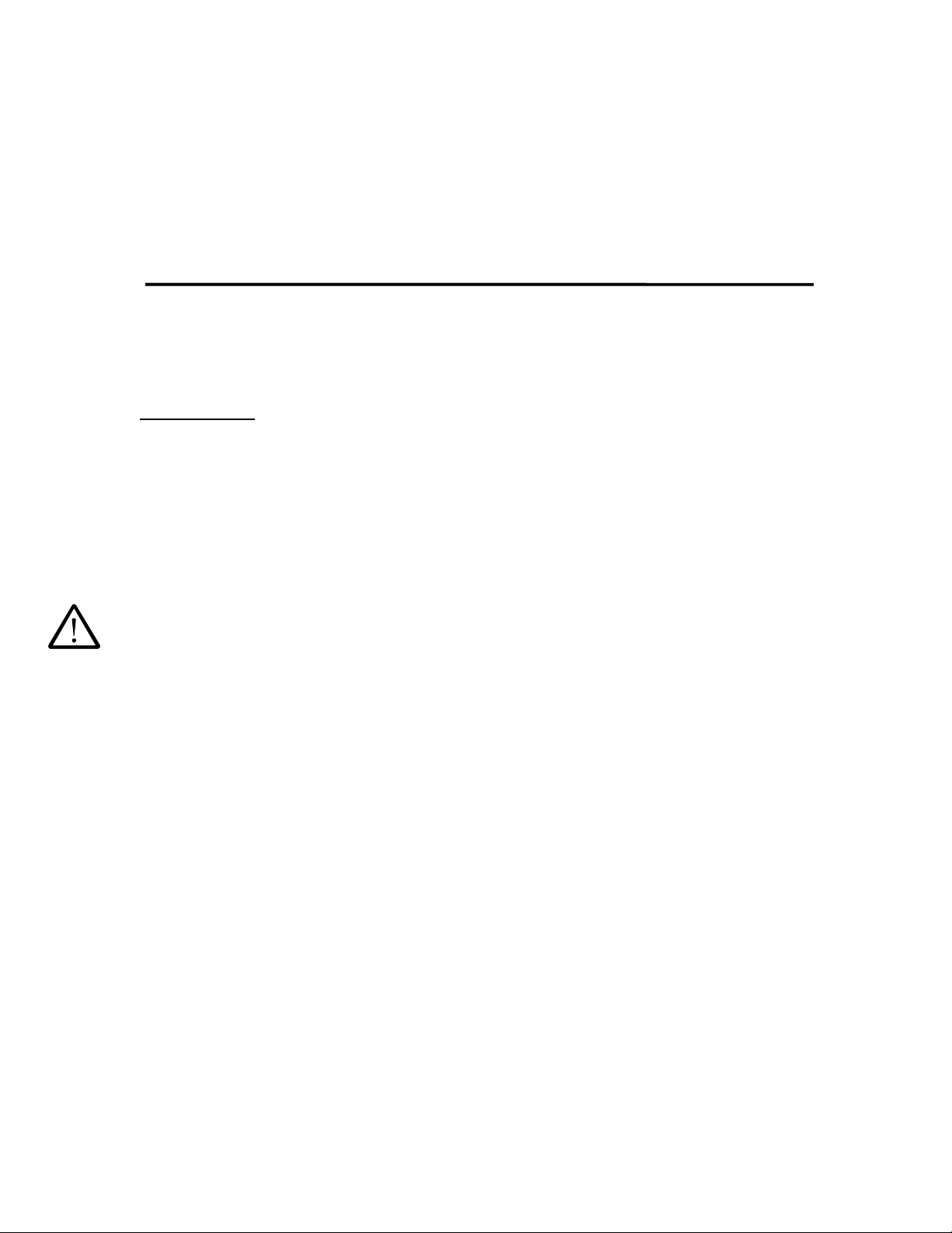
I. Place the removed FMIO module on a convenient workspace, such as an anti-static workbench.
(Figure 1).
Figure 1: Fully-assembled FMIO with Composite board
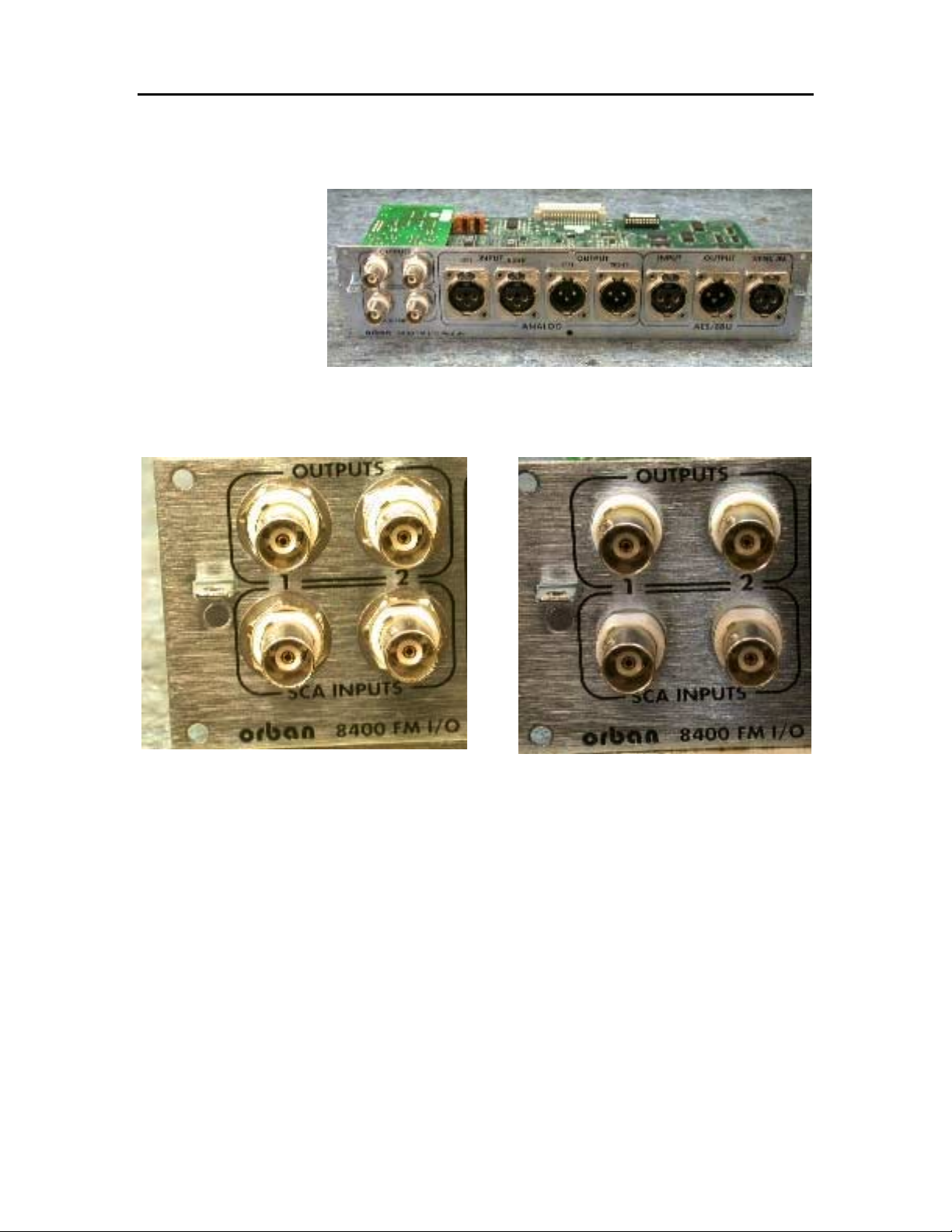
II. Using a 9/16” wrench, remove four hex nuts and washers retaining the BNC connectors for composite
outputs and SCA inputs. (Figure 2 and Figure 3)
Figure 2: Rear-panel FMIO, BNC detail with
hardware
Figure 3: BNC detail, hardware removed
Page 3

Field Engineering Bulletin Page 3 of 5
How to Replace the Composite Output Circuit Board
III. Release XLR inserts from the metal shells riveted to the rear panel. Do not drill out the rivets!
A. IMPORTANT! Use the correct tool to unlock the XLR inserts: “00” size flat-head
screwdriver (Figure 4). Using an improperly-sized screwdriver may damage the locking cam
mechanism, or compromise the chassis grounding integrity to the connector. Because it is the
wrong size, DO NOT use the Orban “greenie” screwdriver for this purpose.
Figure 4: "00" size, flat-head screwdriver
B. Locate the hole in each XLR insert; unlock all inserts with ¼-turn counter-clockwise (Figure
5). When each insert is properly unlocked, a slight movement will be visible from the rear of the
connector with gentle inward pressure on the insert.
Figure 5: Unlocking XLR insert from its shell
Page 4

Field Engineering Bulletin Page 4 of 5
How to Replace the Composite Output Circuit Board
IV. Remove seven (7) Phillips-head machine screws which mount the FMIO printed circuit board to the
rear panel mounting bracket. These screws are situated in-between each XLR shell (Figure 6). A
magnetized screwdriver will make retrieval of the screws easier, and make re-assembly easier.
Figure 6: Board mounting screws, detail
V. With all BNC mounting hardware removed, all XLR inserts unlocked from their shells, and all 7
screws removed, gently
separate the rear-panel bracket away from the connectors (Figure 7).
Figure 7: Separating rear panel from circuit boards
Page 5

Field Engineering Bulletin Page 5 of 5
How to Replace the Composite Output Circuit Board
VI. With the rear-panel bracket completely separated from the circuit boards, the composite board can be
removed for servicing (Figure 8 and Figure 9).
Figure 8: Rear panel removed from FMIO/Composite boards
Figure 9: Composite board removed from FMIO board
VII. To reassemble the FMIO module, reverse the steps above. Carefully check the fully re-assembled
module to make sure that all XLR inserts are properly locked into their shells, and otherwise visually check
for proper mechanical mating of all connectors and headers.
orban
1525 Alvarado Street, San Leandro, California 94577 USA
Phone: 510/351-3500 Fax: 510/351-0500 E-mail: custserv@orban.com
Web: www.orban.com
FTP: ftp.orban.com
 Loading...