

Page 1

Operating Manual
OPTIMOD-FM
2200
Digital Audio Processor
Models 2200 and 2200-D
®
Page 2
IMPORTANT NOTE: Refer to the unit’s rear panel for your Model #.
Model Number: Description:
2200-D/U OPTIMOD-FM 2200 DIGITAL, Stereo Encoder, Digital I/O,
Protection Structure, Two-Band Structure,
set to 115V (for 98-130V operation), switchable to 50µs or 75µs.
2200-D/E OPTIMOD-FM 2200 DIGITAL, Stereo Encoder, Digital I/O,
Protection Structure, Two-Band Structure,
set to 230V (for 196-264V operation), switchable to 50µs or 75µs.
2200-D/J OPTIMOD-FM 2200 DIGITAL, Stereo Encoder, Digital I/O,
Protection Structure, Two-Band Structure,
set to 100V (for 89-120V operation), switchable to 50µs or 75µs.
2200/U OPTIMOD-FM 2200 DIGITAL, Stereo Encoder,
Protection Structure, Two-Band Structure,
set to 115V (for 98-130V operation), switchable to 50µs or 75µs.
2200/E OPTIMOD-FM 2200 DIGITAL, Stereo Encoder,
Protection Structure, Two-Band Structure,
set to 230V (for 196-264V operation), switchable to 50µs or 75µs.
2200/J OPTIMOD-FM 2200 DIGITAL, Stereo Encoder,
Protection Structure, Two-Band Structure,
set to 100V (for 89-120V operation), switchable to 50µs or 75µs.
MANUAL:
Part Number: Description:
96079-000-04 2200/2200-D Manual
CAUTION: TO REDUCE THE RI S K OF ELECTRICAL SHOCK, DO NOT REMOVE COVER (OR BACK ).
NO USER SERV ICEABLE PA RTS INSIDE. REFER SE RVICING TO QUALIFI E D S E RVICE PERSONNEL.
WARNING: TO REDUCE THE RISK OF FIRE O R E LE CTRI CAL SHOCK,
DO NOT EXPOSE THIS APPLIANCE TO RAIN OR MOISTURE.
This symbol, wherever it appears, This symbol, wherever it appears,
alerts you to the presence of uninsul at e d alerts you to important operating and
dangerous voltage inside the enc los ure — volt age maintenance instruc tions i n the ac company i n g
that may be suff icient to constitute a risk of s hock. literature. Read the manual.
Page 3

IMPORTANT SAFETY INSTRUCTIONS
All the safety and operating inst ruc tions shoul d be read bef ore t he applianc e is operated.
Retain Instructions: The saf ety and operati on ins truc t i ons should be ret ai ned for f uture ref erenc e.
Heed Warnings: All warnings on the appliance and in the operat i ng inst ruc ti ons should be adhered to.
Follow Instructions: All operation and user instructions should be foll owed.
Water and Moisture: The appliance should not be used near water (e.g., near a batht ub, was hbowl, kitc hen si nk , laundry tub, in a wet
basement, or near a swimming pool, etc .).
Ventilation: The appliance s hould be situated s o that its locat ion or posit ion does not int erfere wit h its proper ventilat ion. For example, the
appliance should not be situated on a bed, sofa, rug, or similar surface that may block the ventilation openings; or, placed in a built-in
installation, suc h as a book cas e or cabinet that m ay im pede the f low of air t hrough the v ent il at ion openi ngs.
Heat: The appliance should be situated away from heat sources such as radiators, heat registers, stoves, or other appliances (including
amplifiers) that produce heat .
Power Sources: The appliance should be connected to a power supply only of the type described in the operating instructions or as
marked on the appliance.
Grounding or Polarization: Precautions should be taken so that t he grounding or polarizati on means of an appliance is not defeat ed.
Power-Cord Protection: Power-supply cords should be routed so that they are not likely to be walked on or pinched by items placed
upon or against them, paying particular attent ion to cords at plugs, convenienc e receptacles, and the point where they exit from the appli ance.
Cleaning: The appliance should be cleaned onl y as recomm ended by the manuf ac t urer.
Non-Use Periods: The power cord of the appliance shoul d be unplugged from the out let when l eft unused f or a long peri od of time.
Object and Liquid Entry: Care should be taken so that objects do not fall and liquids are not spilled into the enclosure through
openings.
Damage Requiring Service: The appliance should be serv ic ed by quali f ied serv i ce pers onnel when:
The power supply cord or the plug has been damaged; or
Objects have fall en, or li quid has been s pi ll ed into the appliance; or
The appliance has been expos ed t o rai n; or
The appliance does not appear to operate normally or exhibi t s a mark ed change i n perf ormance; o r
The appliance has been dropped, or t he enclosure damaged.
Servicing: The user should not attempt to service the appliance beyond that described in the operating instructions. All other servicing
should be referred to qualified service pers onnel.
The Appliance should be used only with a cart or stand that is recommended by the manufacturer.
Safety Instructions ( European)
Notice For U.K. Customers If Your Unit Is Equipped With A Power Cord.
WARNING: THIS APPL IANCE MUST BE EARTHED.
The cores in the mains lead are coloured in accordanc e wi t h the f oll owing code:
As colours of the cores in the mai ns lead of thi s applianc e may not corres pond wi th the c oloured m ark ings i dent ify ing t he t ermi nals in your
plug, proceed as follows :
The core which is coloured green and yellow must be connec t ed to t he term inal in the pl ug mark ed wi t h the let ter E , or wit h the eart h sy mbol ,
( ), or coloured green, or green and yellow.
The core which is coloured blue must be connect ed to t he termi nal m ark ed N or coloured bl ack .
The core which is coloured brown must be connected t o the t erm inal mark ed L or coloured red.
GREEN and YELLOW - Eart h BLUE - Neutral BROWN - Live
The power cord is terminated in a CEE7/7 plug (Continental Europe). The green/yellow wi re i s connected direc tl y to the unit’s c h assis. If
you need to change the plug and if you are qualified to do so, refer to the ta ble below.
WARNING: If the ground is defeated, ce rtain f ault conditions in the unit or in the system to which it is conne cted ca n result in full line
voltage between chassis and eart h ground. Severe i njury or death can then resul t if the chassis and earth ground are touched simultaneously.
CONDUCTOR
L LIVE BROWN BLACK
NEUTRAL BLUE WHITE
N
EARTH GND GREEN-YELLOW GREEN
E
WIRE COLOR
Normal Alt
AC Power Cord Color Coding
Page 4

Safety Instruct ions ( German)
Gerät nur an der am Leistungsschild verm erk t en Spannung und S tromart bet rei ben.
Sicherungen nur durch solche, gleicher S troms t ärk e und gl eic hen Abs chal t verhalt ens ers et zen. Si cherungen nie überbrücken.
Jedwede Beschädigung des Netzkabels vermeiden. Netzkabel nicht knicken oder quetschen. Beim Abziehen des Netzkabels den
Stecker und nicht das Kabel enf as sen. Beschädigte Netzkabel sofort auswechseln.
Gerät und Netzkabel keinen übert riebenen mec hanis chen B eas pruchungen aus s etz en.
Um Berührung gefährlicher elektris cher Spannungen zu vermei den, darf das G erät nicht geöffnet werden. Im Fall von Betriebsstörun-
gen darf das Gerät nur Von befugten Servicestellen instandgesetzt werden. Im Gerät befinden sich keine, durch den Benutzer
reparierbare Teile.
Zur Vermeidung von elektrischen Schlägen und Feuer ist das Gerät vor Nässe zu schützen. Eindringen von Feuchtigkeit und
Flüssigkeiten in das G erät vermeiden.
Bei Betriebsstörungen bzw. nach Eindringen von Flüssigkeiten oder anderen G egenständen, das Gerät sofort vom Netz trennen und
eine qualifizierte Servi ces t elle k ont ak tieren.
Safety Instruct ions (Fr ench)
On s’assurera toujours que la tension et l a nature du c ourant util isé corres pondent bien à ceux indiqués sur la pl aque de l’appareil.
N’utiliser que des fus ibles de même int ensit é et du même princ ipe de mise hors circui t que les fusibles d’origine. Ne jamais shunter les
fusibles.
Eviter tout ce qui risque d’endommager le câble sec eur. On ne devra ni le plier, ni l’aplatir. Lorsqu’on débranche l’appareil, tirer la fiche
et non le cäble. Si un cäble est endommagé, le rem plac er i mmédiatement.
Ne jamais exposer l’apparei l ou le cäble ä une contrainte mécanique excessive.
Pour éviter tout contact averc une tension électrique dangereuse, on n’oouvrira jamais l’appareil. En cas de dysfonctionnement,
l’appareil ne peut être réparé que dans un at eli er aut oris é. Aucun élément de cet appareil ne peut être réparé par l’utilisateur.
Pour éviter les risques de décharge électrique et d’incendie, protéger l’appareil de l’humidité. Eviter toute pénétration d’humidité ou fr
liquide dans l’appareil.
En cas de dysfonctionnement ou si un liquide ou tout autre objet a pénétré dans l’appareil couper aus sitôt l’appareil de son aliment ation
et s’adresser à un point de serv ice aprés v ent e aut ori sé.
Safety Instructions ( Spanish)
Hacer funcionar el aparato sólo con l a tens ión y clas e de c orriente s eñaladas en la placa indicadora de características.
Reemplazar los fusibles sólo por otros de la misma intens idad de corrient e y sist ema de des conexi ón. No poner nunc a l os f usi bles en
puente.
Proteger el cable de alimentación contra toda clase de daños. No doblar o apretar el cable. Al desenchufar, asir el enchufe y no el
cable. Sustituir inmedi at ament e cabl es dañados.
No someter el aparato y el cable de aliment ac i ón a esfuerzo mecánico excesivo.
Para evitar el contacto con tens iones eléctric as peligrosas, el aparato no debe abrirse. En caso de produc irse fallos de funcionami ento,
debe ser reparado sólo por talleres de servicio autori zados. En el aparato no se enc uentra ninguna pieza que pudiera ser reparada por
el usuario.
Para evitar descargas eléc t ri cas e inc endi os, el aparat o debe prot egers e cont ra l a humedad, impidi endo que penet ren ésta o líquidos
en el mismo.
En caso de producirse fallas de funcionamiento como consecuencia de la penetración de líquidos u otros objetos en el aparato, hay
que desconectarlo inmediat ament e de la red y ponerse en c ont ac to con un t all er de serv ic io a utoriz ado.
Safety Instructions (Italian)
Far funzionare l’apparecchio sol o con la tens i one e il tipo di corrent e indi cat i sul la targa ri port ant e i dat i sull e pres t az ioni.
Sostituire i dispositi vi di protezione (v alvole, fusibil i ecc.) sol o con disposi tivi av enti lo stes so amperaggio e lo stesso co mportamento di
interruzione. Non cavallot t are mai i dis pos iti vi di protez ione.
Evitare qualsiasi danno al cavo di collegamento all a rete. Non piegare o schiac ci are il cavo. Per stac c are il cavo, tirare l a pres a e mai
il cavo. Sostituire s ubito i cavi danneggiati.
Non esporre l’apparecchio e il cavo ad esagerate s ol lec it az ioni mecc ani che.
Per evitare il contatto con le tensioni elettriche pericolose, l’apparecchio non deve venir aperto. In caso di anomal ie di funz ionam ent o
l’apparecchio deve venir ri parato solo da c entri di serv izio autorizz ati. Nell’apparec chio non si trovano parti che possano essere riparate
dall’utente.
Per evitare scosse elet tric he o i nc endi, l’apparecchio va protetto dall’umidità. E v itare c he umidità o liquidi entrino nell’apparecchio.
In caso di anomalie di funzionamento rispettivamente dopo la penetrazione di liquidi o oggetti nell’apparecchio, staccare immedi-
atamente l’apparecchi o dalla ret e e c ont at tare un c ent ro di serv i z io qual ifi cat o.
Page 5

®
PLEASE READ THIS FIRST!
Manual
The Operating Manual contains inst ruc ti ons to verif y the proper operat i on of this unit and init ial izat i on of cert ain opt ions .
You will find these operations are most conv enient ly performed on t he benc h bef ore you i ns tall the unit i n the rac k.
Please review the Manual, es pec ial ly the i ns tall at ion s ect i on, before unpac k ing the uni t .
Trial Period Precautions
If your unit has been provided on a trial bas is:
You should observe the following precaut ions to av oi d rec ondit i oning charges i n case y ou later wi s h to ret urn the unit to
your dealer.
Note the packing technique and sav e all pack ing mat erial s. It is not wi se to s hip in ot her t han t he fac tory cart on. (Replac e-
ments cost $35.00).
(1) Avoid scratching t he paint or plat i ng. Set the uni t on sof t, cl ean surf ac es .
(2) Do not cut the grounding pin from the line cord.
(3) Use care and proper tools in removing and tight eni ng sc rews to avoid burri ng t he heads.
(4) Use the nylon-washered rack screws supplied, i f pos sibl e, to av oid damaging t he panel . S upport the unit when
tightening the screws s o t hat the threads do not scrape the paint ins ide the s l otted holes.
Packing
When you pack the unit for shipping:
Tighten all s crews on any barrier st ri p(s ) so t he sc rews do not fall out from vi brat ion.
Wrap the unit in its original plast i c bag to av oid abradi ng the paint .
Seal the inner and outer cartons wit h tape.
If you are returning the unit permanently (for credit ), be sure t o enc los e:
• The Manual(s)
•
The Registration Card
• The Line Cord
•
All Miscellaneous Hardware (including the Rack Screws)
•
The Extender Card
•
The COAX Connecting Cable
Your dealer may charge you for any missing items.
If you are returning a unit for repair, do not enclose any of the above items.
Further advice on proper packing and shi pping i s inc luded in S ec ti on 5: Troubleshooting.
Trouble
If you have problems with ins tall at ion or operat i on:
(1) Check everything you have done so far agai ns t t he ins truc t ions in t he Manual. The inf orm at ion cont ai ned therein i s
based on our years of experience with OPTIMOD and broadcast stations.
(2) Check the other sections of the M anual (cons ul t the Table of Contents and Index) to s ee i f there mi ght be some
suggestions regarding your problem.
(3) After reading the section on Factory Assist ance, you may call Orban Customer S ervi ce for advice during normal
California business hours. The num ber is (1) 510/351-3500.
Page 6
OPTIMOD-FM 2200 CONDENSED SETUP
Condensed Setup of OPTIMOD-FM Models
2200 and 2200-D
This setup gu ide is f or qualif ied pe rsonne l only. Use this gu ide to h elp you get y our 220 0
installed and ope rating as quick ly as possible. If, at any time, you require more deta ils to
complete installation, refer to the relevant steps in Section 2 of the 2200 Operating Manual.
1. Unpack and inspect. ( Refer to page 2-2.)
A If you note obviou s physical damage, contact the carrier immed iately to make a
damage claim. A complete list of items included in the 2200 package is on page 2-2.
B Save all packing materials, in case you should ever have to ship the 2200.
C Complete the Registration Card and return it to Orban.
2. Change standard factor y configuration, if req ui r ed. (Refer to page 2-3.)
CS-1
[Skip this step if your installation does not have any special requirements.]
The 2200 is s upplied from the f ac tory with its jumpe rs set to th e con figur ation c orre ct
for most installations.
Stereo Encoder Composite Output Impedance 0Ω
Input Impedance 10kΩ
Input Sensitivity −10dBu or greater (+5dBu to +27dBu peak)
A If you are changing any jumper settings, remove the top cover of the 2200 to access
the main circuit board. (Make sure power is not connected.)
B Refer to Figure 2-1 in the manual to find the jump ers on the main c ircuit board and
to position them according to your application .
C Replace the 220 0 top cover.
3. Check the line voltage, f use an d p ow er cord. (Refer to page 2-7.)
A DO NOT connect power to the unit yet!
B Check the voltage selector on the rear panel, and change the setting if it is incorrect.
Refer to the unit’s re ar panel fo r your Model Numb er and the in side o f th e
front cover of the 2200 manual for your Model Number’s line voltage
setting.
C Check the value of the fuse and change the fuse if the value is incorrect.
For safety, the fuse must be Slow-Blow 1⁄2-amp for 115V, or 250mA
1
(
⁄4-amp) “T” type fo r 23 0V.
Page 7

CS-2
QUICK SETUP OPTIMOD-FM 2200
D Check power cord.
If you need to change the plug to meet your country’s standard and you are
qualified to do so, refer to the manual. Otherwise, purchase a new mains
cord with the correct line plu g attach ed .
4. Set Ground Lift swi t ch. ( Refer to page 2-8.)
The
GND LIFT switch, located o n the rear panel, is ship pe d f ro m the fa cto ry se t to GND
(to connect the 2200’s circuit ground to its chassis ground). If you are using the 2200’s
stereo encoder, and are dr iving its composite output into an unbalanced exciter input,
set the
using it to drive a balanced exciter input, set the
GND LIFT switch to LIFT. If you are not using the 2200’s stereo encoder, or are
GND LIFT switch to GND.
5. Mount the 2200 in a r ack. (Refer to page 2-8.)
3
The 2200 requir es on e s tanda rd ra ck un it (1
⁄4 inches/4.4 cm). Th er e shou ld be a goo d
ground connection between the rack and the 2200 chassis — check this with an
ohmmeter to verify that the resistance is less than 0.5Ω.
6. Connect remote contr ol ( optional). (Refer to page 2- 2. )
7. Connect inputs and ou tp ut s. (Refer to page 2-9.)
See the hook-up and grounding information in the manual.
8. Power up the 2200. (r efer to page 2-14.)
A Plug in the 2200’s power cord.
With no i np ut pr og ra m mat eri al, the re d Gat ed LE D and o ne of t he green
Function LEDs should be on. The AGC meter should indicate 10.0. The
main screen app ears in the front window display.
9. Recall Classical Pro tect preset. (Refer to page 2-17.)
A Press Recall Preset button, turn control knob until next: is CLASSICAL PROTECT, then
press the
RECALL NEXT soft key button.
10. Set pre-emphasis to the standard used in your country. (Refer to page
2-18.)
A Press System Setup button, press STEREO ENCODER soft key button, then set
processing (
PROC PRE-E) to your country’s standards:
75µs NORTH, CENTRAL, SOUTH AMERICA
50µs EUROPE, ASIA, AFRICA, P ACIFICA
75
EXCEPT
µs TAIWAN, KOREA, THAILAND
Page 8

OPTIMOD-FM 2200
CONDENSED SETUP
1 1. Set Analo g Outp ut pre-em phasi s. (Refer to page 2-18. )
[Skip this step if you are not using the 2200’s analog outputs.]
A Access ANLG OUTP CALIB control screen: Press System Setup button, press I/O CALIB
soft key button, then press ANLG OUTP CALIB soft key button .
B Set Analog Output pre-emphasis to [flat] or [pre-emph].
This controls whether the analog left/right outputs produce a flat signal, or a
pre-emphasiz ed signal, following the pre- emphasis set with Ster eo Encode r
PRE-E
control in the previous step.
PROC
12. Model 2200-D only: Set Digital O utput pr e-emphasis stat us. (Refer to pag e
2-19.)
[Skip this step if you are not using the 2200-D’s digital output.]
A Access I/O CALIB control screen: Press System Setup button, press the I/O CALIB soft
key button, then press
DIG OUTP CALIB soft ke y bu tt on ..
CS-3
B Set DO PRE-E (Digital Output pre-emphasis status).
See page 2-19 for an explana tion of the the fo llowin g options:
[
flat], [pre-emph], [J.17], or [J.17+pre -e ].
13. Model 2200-D only: Enable Analog Inputs. (Refer to page 2-20.)
[Skip this step if you are not using the 2200-D’s analog inputs.]
A Access ANLG INP CALIB contro l screen: Press System Setu p button, press the I/O
CALIB soft key button, then press ANLG INP CALIB soft key button.
B Enable Analog Inputs.
14. Adjust analog l eft/right input peak cli pping level. (Refer to pag e 2-20.)
[Skip this step if you are not using the 2200’s analog inputs.]
A Press the meter button so that the L/R Channel Input meters are active.
B Access ANLG INP CALIB control screen: Press Sy ste m S etu p butto n, pr es s I/O CALIB
soft key button, then press ANLG INP CALIB.
C Set Analog Input Clip level.
This step calibrates th e level at which the 2200’s A-D (Analog-to-Digital)
converter clips to the absolute maximum peak level that your installation
supplies to the 2200’s analog input.
This setup maximizes the 2200’s signal-to-noise ratio. If the clip level is
set too low, the 2200’s analog-to-digital converters will overload and
Page 9

CS-4
QUICK SETUP OPTIMOD-FM 2200
distort on program peaks. If the clip level is set too high, the signal-to -noise
ratio will suffer. Use care and atten tion in setting this adju stm ent.
a) Play program material from your studio at a much higher level than
normal — turn the fad ers up all th e way! This will produ ce the highest
peak level output that your system can produce .
b) Adjust th e 2200’ s
on the L/R Chan nel Input meters.
AI CLIP so that the program peaks just reach to −3dB
Hold down the button directly below the words “
control knob to scroll from +5.0dBu to +27.0dBu (or −17.0dBu to
+5dBu, if input sensitivity jumpe rs were reset), then release the button.
Observe the L/R Channel Input meters on the 2200 for a long
period of time; be sure to observe live announcer voice. If this
setting is mis-adjusted, distortion will result.
0dB indicates input clipping on the 2200. These meters should
never peak as high as 0dB with pro gram material.
c) If you are using an Orban 4000A Transmission Limiter or Orban
8200ST OPTIMOD ahead of the 2200, activate the tone oscillator on
either unit. Then adjust the 2200’s
Channel Input meters reads −3dB.
AI PEAK so that the 2200’s L/R
AI CLIP,” turn the
15. Calibrate analog in puts to your standar d studio level . (Refer to page 2-22. )
[Skip this step if you are not using the 2200’s analog inputs.]
A Press the meter button so that the L/R Channel Input meters are active.
B Access ANLG INP CALIB control screen: Press Sy ste m S etu p butto n, pr es s I/O CALIB
soft key button, then press ANLG INP CALIB.
C Set Analog Input Reference level.
This step calibrates the 2200 to the level to which your studio operators
peak their program material on the studio meters. This assures that the
2200’s processing prese ts will ope ra te in their preferred range.
If you are able to interrupt or distort programming, use a standard reference/line-up level tone from your studio or pla y program material; this will
achieve the most prec ise calibration . Adjust the appro priate 2200 refe rence
level control (either
on the Master Gain Reduction meter when audio is peaking at normal
levels (e.g., 0VU).
If you cannot interrupt or distort programming, calibrate by numbers,
adjusting the appropria te 2200 ref erence le vel contro l (either
AI REF PPM) to your s tudio’s reference level.
AI REF VU or AI REF PPM) for an average of −10dB
AI REF VU or
16. Model 2200-D only: Enab le Di gital Input. (Refer to page 2-23. )
[Skip this step if you are not using the digital input.]
Page 10

OPTIMOD-FM 2200
A Access DIG INP CALIB control screen: Press System Setup button, press the I/O CALIB
CONDENSED SETUP
soft key button, then press DIG INP CALIB.
Note: If DIG STAT is no lo ck , then the AES/EBU digital input i s not valid .
Check connections, cab ling , an d dig ital sour ce .
B Enable Digital Input.
17. Calibrate Digi tal I n p u t to yo ur stan dard studio level. (Refer to pag e 2-22.)
[Skip this step if you do not hav e Model 2200-D or if you are not using the 2200-D’s
digital input.]
A Pre ss Sy stem Se tup button, press the I/O CALIB soft ke y button, then pr ess DIG INP
CALIB.
B Set Digital Input Reference level.
This step calibrates the 2200 to the level to which your studio operators
peak their program material on the studio meters. This assures that the
2200’s processing prese ts will ope ra te in their preferred range.
If you are able to interrupt or distort programming, pla y program mater ial;
this will achieve the most precise calibration. Then adjust the appropriate
2200 reference level control (either
average of −10dB on the AGC Gain Reduction meter when audio is
peaking at normal levels (e.g., 0VU).
If you cannot interrupt or distort programming, calibrate by numbers,
adjusting the appropriate 2200 reference level control (either
or DI REF PPM) to your studio ’s referenc e level. Note th at the numbers yo u
see represent dB below digital full-scale.
DI REF VU or DI REF PPM) for an
DI REF VU
CS-5
18. Adjust Composi t e Out p u t level co ntrols. (Refer to page 2-25.)
[Skip this ste p if you are not us ing the 22 00 ’s co m po site ou tpu ts. T he se are the outputs
of the 2200’s stereo encoder .]
A Feed the 2200 with program material or activate the built-in 400Hz TEST tone.
To turn on the TEST tone : Press System Setup b utton, p ress TEST sof t key
button, set
control knob to 400 Hz, then release the button), and activate 400Hz test
tone (hold d own the
to
tone, then release the button).
To turn off
control knob to scroll to
B Adjust the 2200’s Comp 1 and Comp 2 level controls — screwdriver slots on the left
TONE to 400Hz (hold down the TONE sof t key b utton, tur n the
MODE soft key button, turn the control kn ob to scroll
TEST tone, hold d own the MODE tone soft key bu tton, turn th e
operate, the n re lea se the button.
side of the fr ont p anel — fo r 100% Total Peak Mod ulation of your F M exc iter, as
indicated on a modulation monitor, or modulation indicator on your exciter.
In the U.S., you can modulate higher than 100% when using SCAs. Refer
to the appropriate FCC rules.
Page 11

CS-6
QUICK SETUP OPTIMOD-FM 2200
19. Adjust Analog Left/Right or Digital Output level controls. (Refer to page
2-25.)
[Skip this step if you are not using the analog Left/Right or Digital Outputs.]
A Access analog or digital output level control: Press System Setup button, then press
ANLG OUTP CALIB or DIG OUTP CALIB as required.
B Set Output level.
Hold down AO 100% or DO 100%, as applicable, and adjust the knob.
Adjust the output level controls for 100% Total Modulation of your FM
exciter, or discr ete left/r ight ST L, a s indica ted on a modulatio n monito r, or
modulation indicator o n your exciter or STL . In the U.S., you can m odulate
higher than 100% when using SCAs. Refer to the ap pr opria te F CC rule s.
20. Select a preset that complements the program format of your station.
(Refer to page 2-26.)
A Press Recall Preset button to access the Recall Preset screen, then select a preset.
21. Quick Setup Compl et ed!
If you want to set up additional input/outp ut parame ters, or re set any setup
adjustments, continue to “System Setup Controls,” starting on page 2-27.
If you are ready to use the 2200, proceed to Section 3 for important 2200
operation informa tion.
Page 12

Operating Manual
OPTIMOD-FM
2200
Digital Audio Processor
Models 2200 and 2200-D
®
Page 13
WARNING
This equipment generates, uses, and can radiate radio-frequency energy. If it is not
installed and used as directed by this manual, it may cause interference to radio
communication. This equipment complies with the limits for a Class A computing
device, as specified by FCC Rules, Part 15, Subpart J, which are designed to provide
reasonable protection against such interference when this type of equipment is operated in a commercial envi ronment . Operat ion of thi s equipm ent i n a res ident i al area is
likely to cause interference. If it does, the user will be required to eliminate the
interference at the user’s expense.
WARNING
“This digital apparatus does not exceed the Class A limits for radio noise emissions
from digital apparatus set out in the Radio Interference Regulations of the Canadian
Department of Communicat ions.” “Le present appareil numerique n’emet pas de bruits
radioelectriques depassant les limites applicables aux appareils numeriques (de las
class A) prescrites dans le Reglement sur le brouillage radioelectrique edicte par le
ministere des Communications du Canada.”
IMPORTANT
Perform the installation under static control conditions. Simply walking across a rug can
generate a static charge of 20,000 volts. This is the spark or shock you may have felt when
touching a doorknob or some other conductive item. A much smal ler static disc harge is likely to
completely destroy one or more of the CMOS semiconductors employed in OPTIMOD-FM.
Static damage will not be covered under warranty.
There are many common sources of static. Most involve some type of friction between two
dissimilar materials. Some examples are combing your hair, sliding across a seat cover or
rolling a cart across the floor. S ince t he thres hol d of human percept ion f or a stat ic dis charge is
3000 volts, many damaging dis c harges will not even be noticed.
Basic damage prevention consists of minimizing generation, discharging any accumulated
static charge on your body or work station and preventing t hat dis charge f rom bei ng sent to or
through an electronic component. A static grounding strap (grounded through a protective
resistor) and a static safe workbenc h with a conductive surfac e should be used. This will prevent
any buildup of damaging static.
The OPTIMOD-FM 2200 Digi t al A udi o P roc es s or is protected by U.S. pat ent s 4,208,548; 4,249,042; 4,412,100; 4, 460,871; 5,050,217;
and U.K. patent 2,001, 495. Other patents pending.
Orban is a registered trademark.
All trademarks are property of their res pec ti ve compani es .
This manual is part number 96079-000-04
Copyright 2000
1525 Alvarado Street, San Leandro, CA 94577 USA
Phone: (1) 510/351-3500; Fax: (1) 510/351-0500; E-mail: custserv@orban.com; Web: www.orban.com
Page 14

OPTIMOD-FM
Operating Manual
page contents
1-1 Section 1: Introduction
OPTIMOD-FM 2200 DIGI TAL Audio Processor
Presets in the 2200
The T wo-Band Str uctur e
Protection Limiting: Orban’s Approach
Input/Output Configurations
Location of OPTIMO D-F M
About Trans m iss ion Lev els and M eter ing
Line-Up Facilities
Warrant y, Feedback
Orban
2200
2-1 Section 2: Installat ion
Installation of 2200
Basic System Setup
System Setup Controls
3-1 Section 3: Operation
2200 Controls and Meters
Introduction to Processing
About the Processing Struct ures
Factory Programming Pres et s
Customizing the 2200’s Two-Band Sound
T wo-Band St ruct ur es Pr oces sing Cont rols Det ails
Customizing the Protect ion Lim it er St r uct ur e Sound
2200 Screen Displays
Continued on next page
Page 15

OPTIMOD-FM
Operating Manual
page contents
4-1 Section 4: Maintenance
Routine Maintenance
Getting Inside the Chassis
In-System Testing (“Proof of Performance”)
Field Audit of Performance
Field Alignment
Orban
2200
5-1 Section 5: Troubleshooting
Problems and Possible Causes
Troubleshoot ing IC O pam ps
Technical Support
Factory Service
Shipping Instructions
6-1 Section 6: Technical Data
Specifications
Circuit Description
Parts List
Schematics, Assembly Dr awings
Abbreviations
INDEX on next page
Page 16

Index
!
4000 2-21
8200ST 2-21
A
abbreviations 6-51
AC line cord wire standard 2-7
AGC
defeating 3-13
AGC meter 2-16
analog input clip level 2-21, 2-29
analog input reference level 2-22, 2-28
analog input sensitivity 2- 4
analog input termination 2-3
analog inputs 2-20, 2-22
assembly drawings 6-34
audible di stortion 3-5, 5-2
audible no ise 5-3
audio
connections 2-10
input 2-10, 6-2
output 2-11, 6-2
B
balanced
inputs 2-10
output transformer 2-11
bass equalizati on 3-11
Bass meter 2-16
block diagram 6-35
buttons
Function 2-16
buzzes 5-2
bypass gain 2-36
bypass mode 2-35
bypass preset 1-10
C
cable 2-8, 2-10
cable shie lding 2-10 - 2-11
chassis
getting inside 4-3
ground 2-12
circuit boards
access to 4-3
front pane l 4-3
circuit description 6-5
circuit ground 2-12
CIT25 0-2, 2-8
cleaning 4-2
clicks 5-2
clipping 3-5
common-mode rejection 2-10, 2-1 2
Comp 1 level control 3-4
Comp 2 level control 3-4
composite
isolation transformer 0-2, 2-8
metering 1-9
composit e level control 2-1 6
composit e level output 2-16
Composite meter 2-16, 3-4
composite output impedance 2-3
compression 3-5
computer inte rfa ce 0-2
connectors
audio 2-10
Constrast bu tt on 3-3
Contrast
control 2-15, 3-3
control knob 2-15, 3-3
controls 2-15, 3-3
Comp 1 3-4
Comp 2 3-4
Composite 1 2-16
Composite 2 2-16
Contrast 2-15, 3-3
Escape 2-15
Escape bu tton 3-3
Modify Processing 2-16
System Setup 2-16
crosstalk test 2-33
customer service 5-7
D
D-connector 6-9
dBm (defined) 6-51
dBu (defined) 6-51
density 3-14
digital i/ o 1-6
digital in pu t 2-23, 2-30
digital input/output connectors 2-11
digital ou tp ut 2-30
distortion 5-2
dull sound 5-4
E
EBS tones
failure 5-5
enabling analog inputs 2-20
enabling digital input 2-23
Escape butt on 2-15, 3-3
exciter interface 2-13
F
factory service 5-8
field audi t 4-16
final clip pe r d riv e 3-17
frequency response verification 4-16
front panel 2-15, 3-3
Function button 2-16, 3-4
Function meter 2-16 , 3-4
fuse 2-7
G
gain reduct ion 3-14, 3-19
meters 3-4
Gain Reduction meters 2-16
gate compressor 3-13
Gated LED 2-16, 3-4
gating 3-13 - 3-14
grounding 2-1 2 - 2-13 , 5-2
diffic ul t si tu ations 0-2, 2-8
ground loop 0-2, 2-8
H
harshness 5-4
HF Limiting 2-16, 3-4, 3-15
LEDs 2-16
high-frequency
limiting 3-15
high-pass filter 3-11
protection structure 3-19
hum 5-2
I
impedance 2-10 - 2-11
input
balanced 2-10
impedance 2-10
level 2-10
overloa d point 2-10
sensitivity 2-4
termination 2-3
unbalanced 2-10
input leve l
line-up 1-8
input leve l me ters 1-9
input select A or D 2-28, 2-30
inspecti on of contents 0-1 , 2- 2
installation 2-1
internal cloc k 2-30
introduction 1-1
J
jumpers
access to 4-3
analog I/O card 2-3
input sensitivity 2-4
options 2-3
L
L-R null 4-11
LEDs
Gated 2-16, 3-4
HF Limiting 2-16, 3-4
limiting 3-5
high-freque nc y 3-15
line voltage 2-7
line-up tones
failure 5-4
location 2-8
location of 2200 1-7
digital in pu t 2 -30
loudness 3-5, 3-14
Page 17

M
mainsub 2-33
maintenance, routine 4-2
Master meters 2-16
meters
AGC 2-16
Bass 2-16
Composite 2-16 , 3-4
Function 2-16, 3-4
Gain Reduction 2-16
Master 2-16
PPM 2-22 - 2-23
studio 1-7
VU 2-22 - 2-23
Modify Processing
control 2-16
modulation
cannot control 5-2
modulation mode 2-33
mono
performance verification 4-8
mono left 2-33
mono right 2-33
mono sum 2-33
mono/stereo select 2-33
N
noise and distortion verific at io n 4 -16
O
operate mode 2-35
operation 3-1
ordering parts 6-23
output
impedance 2-11
level 2-11
unbalanced 2-11
output level meters 1-9
overshoot 5-2
P
packing for shipmen t 5-8
packing li st 2-2
parts
list 6-22
ordering 6-23
peak cont rol 3-16
peak modulation
cannot control 5-2
physical dimensions 6-4
pilot leve l 2-33
pilotoff 2-33
power 0-2, 2-7
cord 0-2, 2-6 - 2-7
requirements 6-4
PPM meter 2-22 - 2-23
pre-emphasis 2-30, 3-5
selection 2-18, 2-32, 2-35 - 2-36
problems 5-2
processing st ructures 3-7
remote control 2-34
programming prese ts 3-7
proof of performance 4-7
protectio n li mi ter structure
high-pass fi lt er 3-19
R
rack-mounting un it 2-8
rear panel
connections 2-6
digital in pu t 2 -30
registration card 1-10
remote control 0-2, 2-9
return authoriza tion 5-8
RF suppression 5-2
RFI 2-7, 2-13
filter 2-7
rotary encoder
control knob 2-15
controls 3-3
S
digital ou tp ut 2-31
schematics 6-34
screen
contrast 3-3
display 3-3
saver 3-3
screen displa ys 2-15
screen saver 2-15
screens
Constrast button 2-15
presets 2-26
selectin g a preset 2-26
service 5-8
setup
expanded 2-27
system 2-17
shipping
damage 0-1, 2-2
instructions 5-8
shrilln ess 5-4
soft keys 2-15, 3-3
specifications 6-2
spectral gain intermod ul at io n 1-5
stereo
interference 5-5
performance verification 4-10
stereo modu la tion 2-33
stereo/mono select 2-33
structures
two-band 1-4
submain 2-33
subcarrier input 2-12
digital ou tp ut 2-31
System Setup 2-1 6 - 2-17 , 3-4
T
technical support 5-7
temperature 2-8
test mode 2-35
test tone 2-36
tone 2-36
tone generator
internal 1-10
tone mode 2-35
troubleshooting 5-1
IC opamps 5-7
two-band structure
bass eq 3-11
setup 3-13
two-band structures 1-4
gating 3-13
high-frequency limiting 3-15
high-pass filter 3-11
loudness, densit y 3-14
peak control 3-16
setup 1-4
spectral balanc e 3-15
U
unbalanced
input 2-10
load 2-11
user tone pres et 1-10
V
VU meter 2-22 - 2-23
W
warranty 6-4
whistle, on air 5-4
X
XLR connectors 1-6, 2-10
Page 18

OPTIMOD-FM 2200 INTRODUCTION
pagecontents
Section 1
Introduction
page contents
1-3 OPTIMOD-FM 2200 DIGITAL Audio Processor
1-4 Presets in the 2200
1-4 The Two-Band Structure
1-1
1-5 Protection Limiting: Orban’s Approach
1-6 Input/Output Configurati ons
1-7 Location of OPTIMOD-FM
1-7 About Transmission Levels and Metering
1-8 Figure 1-1: Absolute Peak Level, VU and PPM Reading
1-9
1-10 Warranty, Feedback
Line-Up Facilities
Page 19

1-2
INTRODUCTION OPTIMOD-FM 2200
Page 20

OPTIMOD-FM 2200 INTRODUCTION
OPTIMOD-FM 2200 DIGITAL Audio Processor
Orban’s OPTIMOD-FM 2200 DIGITAL Audio Processor is a complete audio processing
system for FM br oadcas t. Mode l 2200 is conf igured fo r analog inp uts and outputs . Model
2200-D also includes digital inputs and outputs. Features for all versions include:
Universal transmitter protection and audio processing for FM broadcast. The
•
2200 can be configured to interface ideally with any commonly-found transmission system in the world .
User-friendly Interface: A simple liquid-crystal display (LCD) makes setup,
•
adjustment and pro gramming easy. Front panel bar graphs show me tering fu nctions of the proce ss ing pre set in use. Push one of th e cle ar ly lab ele d soft keys to
RECALL a preset, to MODIFY PROCESSING, or to access SYSTEM SETUP
controls.
8 factory-programmed presets, based on Orban’s Two-Band and Protection/Lim-
•
iting Processing Structures. These presets can be modified and saved.
1-3
8 user presets to store customized settings.
•
Pre-emphas is limiting for the in ternationally -used pre-e mphasis cur ves of 50µs
•
and 75
µs. The pre-emphasis control is almost never audibly apparent, producing
a clean, open sound with subjective brightness matching the original program.
Extremely tight peak control; overshoot is limited to ±0.3dB!
•
DSP-based stereo encoder (stereo generator) produces a circuit with excellent
•
specs, high stability, and uncompromis ing baseband spec trum control.
Remote-control, via optically-isolated terminals that can be operated with contact
•
closures (to facilitate interfacing to older-technology remote controls).
Built-in line-up tone generator facilitating quick and accurate level setting in any
•
system and a Bessel Null tone for calibrating modulation.
Page 21

1-4
INTRODUCTION OPTIMOD-FM 2200
Presets in the 2200
There are two distinct kinds of pr esets in the 2200: Facto ry Processing P resets and User
Presets.
The 8 Factory P rocessin g Prese ts include a protec tion/limiting pres et, a two-ban d general
purpose pres et, an d 6 oth er pr es ets de rived from th e two- band s tructu re. A ll of the fac tory
processing presets are stored in the 2200’s non-volatile memory, and cannot be erased. You
can change the settings of a Factory Processing Preset, but you must then store those settings
as a User Prese t. The fa ctory pre set rema ins uncha nged. You may sto re your new settings
in one of the 8 numbered User Presets.
User Presets cannot be created from “scratch.” You must always start by recalling a Factory
Preset, make changes, then store the changes in a User Preset.
The Two-Band Structure
The Two-Band Structure consists of a slow single-band gated AGC (Automatic Gain
Control) for g ain riding, followed by a gated two-band compr essor and a high- frequency
limiter. A two-band equalizer is available before the input of the Two-Band structure.
The Two-Band Structure is an improved version of Orban’s classic 8100A OPTIMODFM, but with increased high frequency clarity. (This is the same structure used in our
OPTIMOD-FM 8200.) It is ope rated after a phase ro tator (time-di spersion filte r) to improve
its loudness capability b y making positive an d negative pea ks more symmetric al, particularly with voice.
The Two-Band Structu re has an o pen, easy-to -listen-to so und that is simila r to the source
material if the source material is of good quality. However, if the spectral balance between
the bass and high- frequency energy of the pro gram material is incorrect, the Two- Band
Structure ( when its ba ss coupling control —
gently correct it without introducing obvious coloration.
Two-Band Presets
The Two-Band Factory Programming Presets are designed to help you get on the air quickly.
In most cases, th ey will su it yo ur needs without the need for further adju stme nt. Or , if yo u
desire, you can always experiment with the
to your taste.
The basic Two-B and prese t, 2B G ener al Pur pose , pr ovide s an ave ra ge amou nt of p roce ssing. The other Two-Band presets provide a sound tailored for a specific program format. For
example, Mus ic-Light produces a very open, unprocessed sound while Music+Bass Me dium provide s a very punchy, clean, open so un d. P re se ts in clu de:
TALK, MUSIC-LIGHT, MUSIC-MEDIUM, MUSIC HEAVY, MUSIC+BASS MEDIUM and MUSIC+BASS HEAVY.
BASS COUPL — is operated toward 0%) ca n
LESS-MORE control to fine-tune the processing
2B GENERAL PURPOSE,
Page 22

OPTIMOD-FM 2200 INTRODUCTION
Using the Two-Band Structure for Classical M u si c
Classical music is traditionally broadcast with a wide dynamic range. However, with many
recordings a nd live performances, th e dynamic range is so grea t that the quiet passages
disappear into the noise on most car, portable, and table radios. As a result, the listener either
hears nothin g, or must turn up the volume control to hear all the mus ic. Then, when the
music gets loud, the radio blasts and distorts, making the listening rather unpleasant.
The Two-Band S tructure is well-suited for classical for mats during daytime hours when
most people in the a ud ien ce a re lik ely to b e liste nin g in a uto s o r to be us ing the sta tion fo r
background mus ic. This audience is best served when the dynamic rang e of the program
material is compressed 10-15dB so that quiet passages in the music never fade into
inaudibility under these less-favorable listening conditions. OPTIMOD-FM controls the
level of the music in ways that are, for all practical purposes, inaudible to the listen er.
Low-level passages are increased in level by up to 10dB, while the dynamics of crescendos
are maintained.
The same station ma y wish to sw itch to the P rotec tion Structu re durin g the eve ning hour s
when the audience is more likely to listen critically.
1-5
Protection Limiting: Orban’s Approach
The Protection Limiter Structure is designed for stations wanting the highest possible
fidelity to the source, such as a station broadcasting concert music at night when it’s
audience is likely to listen in a more critical manner. While the Protection Limiter Structure
can readily red uce the dynamic ra nge, it is design ed to do so withou t increasing program
density, loudness, or the consistency of sound from different sources. It’s primary function
is to protect th e tra ns mitter f ro m o ve r- de via tion wh ile pr es erving the spectr al an d te xtu re d
quality of the source material.
The 2200 has one Protection Limiter factory preset , named
Traditionally, protection limiters have used peak-sensing automatic gain control (AGC)
processors to control peak levels. This approach ignores one crucial requirement for
protection limiter performance: the limiter must provide natural-sounding con trol that is
undetectable to the ear except by an A/B compar ison to the original source material. To
achieve natur al sound quality , the gain con trol s ection of the limiter mus t re spond lik e the
ear. This means that the gain control must respond approximately to the power (not the peak
level) in the signal. Further, because the sensitivity of the ear decreases dramatically below
150Hz, the control must be frequency-weighted to compensate. Otherwise, heavy bass
would audibly modulate the loudness of midrange program material, a problem called
spectral gain interm odulation.
CLASSICAL PROTECT.
Page 23

1-6
INTRODUCTION OPTIMOD-FM 2200
Input/Output Configurations
The OPTIMOD-FM 2200 DIGIT AL is de sig ne d t o simu l tan eo us ly ac co m mod ate :
analog left/right inputs and outputs
•
Digital AES/EBU left/righ t in put s an d ou tput s (Mod el 22 00 -D on ly)
•
stereo analog baseband composite output
•
Analog Left/Right In put/Ou tp ut
The left and right analog inputs are on XLR-type female connectors on the rear panel. Input
impedance is greater than 10kΩ; balanced and floating. Inputs can accommodate up to
+27dBu (0dBu = 0.775Vrms). The left and right analog outputs are on XLR-type male
connectors on the rear panel. Output impedance is 30Ω; balanced and floating. Outputs can
drive up to +20dBm into 600Ω.
Level control of the analog inputs and outputs is via software control through SYSTEM
SETUP. (See page 2-20 an d 2-6. )
Digital AES/EBU Lef t/Ri ght Input/Output (Model 2200-D only)
The digital input and output follow the professional AES/EBU standard. The left/right
digital input is on one XLR- type female connector on the rear pan el; the left/righ t digital
output is on one XLR-type male con necto r on the rear pan el.
The 2200-D is designed to simultaneously accommodate digital and analog inputs and
outputs. You sele ct whether the 2 200-D uses the digital o r the analog input via s oftware
control through System Setup (
interface. Both analog and digital outputs are active continuously. Level control of the
AES/EBU input is via so ftwa re con trol th roug h Sys tem Set u p.
The 2200-D’s digital I/O operates at a 32kHz, 44.1kHz, or 48kHz sample rate. Its output can
be flat, pre-emphasized (to the 50µs or 75µs curve selected for the processing), J.17
pre-emphasized, or J.17 plus 50µs or 75µs pre-emphasized.
Please note that the AES/EBU standard is not the same as the S/P-DIF
(Sony/Philips Digital Inte rface) standard use d in consum er digita l applica tions, such as the “digital outputs” of CD player s. The AES/EBU inte rface
will not work with S/P-DIF signals.
A 2200 cannot be upgraded to a 2200-D.
DIG INP CALIB or ANLG INP CALIB screen), or by remote
Stereo Analog Baseband Compo site Ou tp ut
The stereo encoder has two unbalanced analog baseband outputs on two BNC connectors
on the rear pan el. Each ou tput can b e strapp ed for 0Ω or 75Ω so urce impedan ce, and can
drive up to 8V peak-to-peak into 75Ω in parallel with up to 0.047
cable) before any noticeable performance degradation occurs.
µF (100ft/3 0m of RG- 59/U
Page 24

OPTIMOD-FM 2200 INTRODUCTION
Level control of eac h ou tput is via a separate screwdriver co ntrol accessible from th e fro nt
panel.
A ground lift s witch is ava ilable on th e rear p anel. This is u seful to preve nt ground loops
between the 2200 and the transmitter.
Location of OPTIMOD-FM
Best Location for OP T IM O D-F M
The best location for OPTIMOD-FM is as close as possible to the transmitter, so that its
stereo encoder output can be connected to the transmitter through a circuit path that
introduces the least possible change in the shape of OPTIMOD-FM’s carefully peak-limited
waveform — a short length of coaxial cable.
We very stro ngly re comm end that yo u use the 22 00’s internal st ereo e ncoder a nd feed
its output directly to the baseband input of the exciter through less than 100 feet (30
meters) of coaxial cable. You wi ll achieve a louder sound on the air, with bet ter control
of peak modulation, than if you use an external stereo encoder.
1-7
About Transmission Levels and Metering
Meters
Studio engineers and transmission engine ers consider audio levels and their measuremen ts
differently, so they typically use different methods of metering to monitor these levels.
The VU meter is an average- responding mete r (measuring the appr oximate RMS leve l) with
a 300ms rise time an d de ca y time; th e VU in dic ation u su ally un de r- indicates the true pea k
level by 8 to 14dB.
The Peak Program Meter (PPM) indicates a level between RMS and the actual peak. The
PPM has an attack time of 10ms, slow enough to cause the meter to ignore narrow peaks
and under-indicate the true peak level by 5dB or more.
The absolute peak-sensing meter or LED indicator shows the true p eak level. It has an
instantaneous attack time, and a release time slow enough to allow the e ngineer to eas ily
read the peak level.
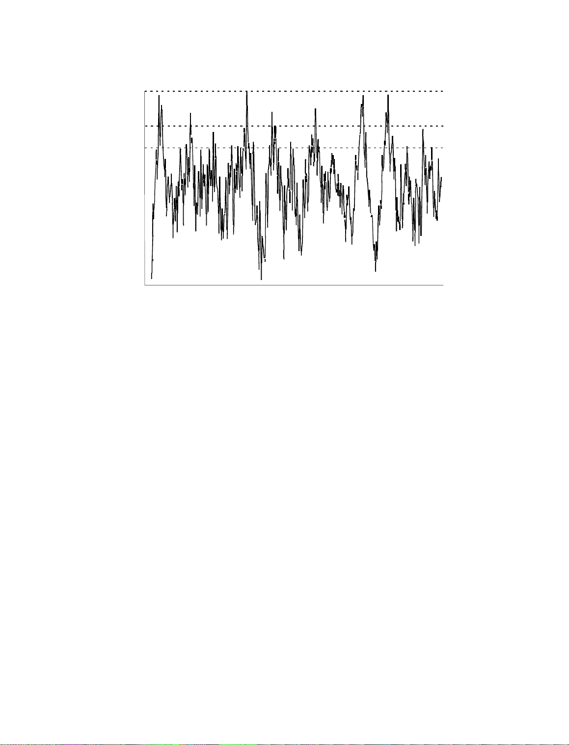
Figure 1-1 shows the relative difference between the absolute peak level, and the indications
of a VU meter and a PPM.
Page 25
1-8
INTRODUCTION OPTIMOD-FM 2200
ABSOLUTE PEAK
PPM
VU
Figure 1-1: Absolute Peak Lev el, VU and PPM Reading
For a Few Seconds of Music Pr ogram
Studio Line-u p Levels and Headroom
The studio enginee r is primarily con cerned with calibr ating the equipment to prov ide the
required input level for proper operation of each device, and so that all devices operate with
the same input and output levels. This facilitates patching devices in and out without
recalibration . For line-up, the s tudio engineer uses a calibration tone at a stud io standard
level, commonly called line-up level, reference level, or operating level.
Metering at the studio is by a VU meter or PPM (Peak Program Meter). As discussed above,
the VU or PPM indi c ati o n l a gs the t ru e p ea k l evel. Most modern st ud io a udio devices have
a clipping level of no less than +21dBu, and often +24dBu or more. So the studio
standardizes on a maximum program indication on the meter that is lower than the clipping
level, so that pea ks that the meter doesn’t indicate will no t be clipped. Line-up level is
usually at this same maximum meter indication.
In facilities that use VU meters, this level is usually at 0VU, which corresponds to the studio
standard level, typically +4 or +8dBu. For facilities using +4dBu standard level, instantaneous peaks can reach +18dBu or higher (particularly if the operator overdrives the console or
desk). Older facilities with +8dBu standard level and equipment that clips at +18 or +21dBu
will experience noticeable clipping on some program material.
In facilities that use the BBC-standard PPM, maximum program level is usually PPM4 for
music, PPM6 f or speech. Line-up leve l is usually PPM4, which corres ponds to +4dBu.
Instantaneous peaks will reach +17dBu or more on voice.
In facilities that use PPMs that indicate level directly in dBu, maximum program and line-up
level is often +6dBu. Instantaneous peaks will reach +11dBu or more.
Page 26

OPTIMOD-FM 2200 INTRODUCTION
T ran smi ssi on Levels
The transmission engineer is primarily concerned with the peak level of a program to
prevent ove rloading or over-modulatio n of the transmission s ystem. This peak overloa d
level is defined differently, system to system. In FM modulation (FM/VHF radio and
television broadc as t, micr owave or an alo g sa tellite links ), it is the maximu m-p er mitted RF
carrier fr equency de viation. In AM modulation, it is negative c arrier p inch-off. In analog
telephone/post/P TT transmission, it is the le vel above which serious cr osstalk into other
channels occurs, or the level at which the amplifiers in the channel overload. In digital, it is
the largest possible digital word.
For metering, the transmission engineer uses an oscilloscope, absolute peak-sensing meter,
calibrated peak-sensing LED indicator, or a modulation meter. A modulation meter usually
has two compone nts — a semi -peak readi ng meter (like a PPM) , and a p eak-indi cating l ight
which is calibrated to turn on whenever the instantaneous peak modula tion exceeds the
over-modulation threshold.
Line-Up Facilities
1-9
Metering of Levels
The 2200’s front panel metering includes bargraphs displaying the following I/O levels: L/R
Input, L/R Output and Composite Output.
L/R Input Level
Left and right input level is shown on a VU-type scale (0dB to −27dB), while the metering
indicates absolute instantaneous peak (much faster than a standard PPM or VU meter ). 0dB
indicates A/D conve rter clipp ing (analog input) or digital full-s cale (digita l input, 2200-D
only).
Left/Right Output Level
Left and right output level is shown on a VU-type scale (0dB to −27dB), where the metering
indicates absolute instantaneous peak (much faster than a standard PPM or VU meter).
The meter is sca led so tha t 0dB is calibrate d to the highest left a nd right pea k modulation
level, before de-emphasis, that the processing will produce, under any program, processing,
or setup condition (except when the processing is switched to bypass). The meter indication
is not affected by the setting of the analog or digital output level control.
Composite Output Level
The Orban 2200 Audio Processor controls instantaneous, absolute peak levels to a tolerance
of approximately ±0.3dB. Composite modulation is indicate d in % modulation, absolute
instantaneous peak indicating. 100% is calibrated to the highest composite peak modulation
level that the processing will produce, including the pilot tone, under any program, processing, or setup condition (except when the processing is switched to bypass). 100% ordinarily
corresponds t o ±75kHz carrier deviation.
Page 27

1-10
INTRODUCTION OPTIMOD-FM 2200
Built-in Calibrated Line-up Tones
To facilitate matchin g the output level of the 2200 to the tra nsmission system that it is
driving, the 2200 c ontains an adjustable ton e that produces sine w aves at 2200’s analog ,
digital and compos ite ou tputs. The frequen cy of the lin e- up tone s can be ad jus ted fr om the
front panel. The modulation is always 100%.
When the 2200’s left/right analog output is switched to flat, a de-emphasis filter is inserted
between the output of the 2200’s audio processing and its line output. Thus, as the frequency
of the tone pres et is changed, the level at the 2200 ’s line output will follow the selecte d
de-emphas i s cu rv e.
In most cases the pre-empha sis filter in the dr iven equipment w ill undo the effect of th e
2200’s internal de-emphasis, and the 2200’s output level should be adjusted so that the tone
produces 100% modulation of the transmission link as measured after the link’s pre-emphasis filter. At 100Hz, switchin g the de- emphasis out or in will ha ve ne gligible ef fect o n the
level appearing at the 2200’s left and right audio outputs.
Built-in Calibrated Bypass
Bypass is available to transparently pass line-up tones generated earlier in the system. It will
also pass program material, with no gain reduction or protection against overmodulation. It
can transparently pass any line-up tone applied to its input up to about 130% output
modulation, at w hich point c lipp ing ma y oc cur. Acc ess b ypas s in the S ystem S etup TEST
MODE screen.
Note that BYPASS applies 50µs or 75µs pre-e mphasis, as determined by the setting of
PROC PRE-E, in the System Setup STEREO ENCODER screen.
Warranty, Feedback
Warranty
The warranty, whic h can be enjo yed only by the first end- user of reco rd, is located on the
inside back cover of this manua l. Sa ve it fo r futu re re fe renc e. De tails on ob taining factor y
service are provided on page 5-9.
User Feedback Form
We are very interested in your comments about this product. Your suggestions for improvements to either the product or the manual will be carefully reviewed. A postpaid User
Feedback Form is provided in the back of this manual for your convenience. If it is missing,
please write us at the address printed in the front of the manual, or call or fax our offices at
the number listed. We will be happy to hear from you.
Page 28

OPTIMOD-FM 2200 INSTALLATION
Section 2
Installation
page contents
2-2 Installation of 2200
2-7 Figure 2-1: AC Line Cord Wire Standard
2-9 Figure 2-2: Wiring the 25-pin Remote Control Connector
2-1
2-17
2-27 System Setup Controls
2-27 I/O CALIB (I/O Calib rat ion )
2-32 Stereo Encoder (and processing Pre-Emphasis)
2-34 Remote Inte rface
2-35 TEST Mod e
Basic System Setup
CAUTION
The installation and servicing instructions in this manual are for
use by qualified personnel only. To avoid electric shock, do not
perform any servicing other than that contained in the Operating
Instructions unless you are qualified to do so. Refer all servicing
to qualified service personnel.
pagecontents
Page 29

2-2
INSTALLATION OPTIMOD-FM 2200
Installation of 2200
Allow about 2 hours for installation.
Installation co nsists of: (1) unpacking and insp ecting the 2200, (2) optional rese tting of
jumpers for 2200 op tions (compos ite output impedance , input termination, inp ut sensitivity), (3) checking the line voltage setting, fuses and power cord, (4) mounting the 2200 in a
rack, (5) connecting inputs, outputs and power, (6) setting the
optional connecting of remote control leads.
When you have finished installing the 2200, proceed to “System Setup,” on page 2-16.
1. Unpack and inspect.
A If you note obviou s physical damage, contact the carrier immed iately to make a
damage claim. Packed with the 2200 are:
1 Operating Manual
1 Quick Setup Guide
1Line Cord
2
1
⁄2A Replacement Fuses for “U” and “J” V ersions
2 250mA Replacement Fuses for “E” Version
1 Orban green screwdriver (Xcelite R3323)
1 Booklet: Audio Quality in the FM Plant
GROUND LIFT switch, (7 ) and
B Save all packing materials! If you should ever have to ship the 2200 (e.g., for
servicing), it is best to ship it in the original carton with its packing materials because
both the carton and packing material have been carefully designed to protect the unit.
C Complete the Registration Card and return i t to Orban. (please)
The Registration Card enables us to inform you of new applications,
performance improve ments, and service aids tha t may be develo ped, and it
helps us respond promptly to cla ims unde r warr anty with out our hav ing to
request a copy of your bill of sale or other proof of purchase . Please f ill in
the Registration Card and send it to us today. (The Registration Card is
located aft er the cover page).
We do not sell or give away our customer’s names to anyone.
Page 30

OPTIMOD-FM 2200 INSTALLATION
2. Change standard factor y con fi g uration, if required.
[Skip this step if your installation does not have any special requirements.]
The 2200 is s upplied from the f ac tory with its jumpe rs set to th e con figur ation c orre ct
for most installations.
Stereo Encoder Composite Output Impedance 0Ω
Input Impedance 10kΩ
Input Sensitivity −10dBu or greater (+5dBu to +27dBu peak)
A To change any jumpers you must remove the top cover of the 2200 to access the main
circuit board. (Make sure p ower is not con nected. ) Remove all scr ews ho lding the
cover in place, then lift it off. (B e caref ul not to strip threads when opening the
cover.)
B Refer to Figure 2-1 to find the jumpers on the main circuit board and to position them
according to your application.
The following inf ormation is provided to explain each jumper and its settings in detail.
2-3
Stereo encoder composite output impedance.
•
[Do not change the default 0Ω jumper setting unless your installation
needs 75Ω source impedance.]
The stereo encoder is shipp ed from the facto ry with 0Ω source impedan ce.
This is correct for virtually all installations. However, the 2200 stereo
encoder can be changed to 75Ω source impedance if desired.
The frequencies in the stereo baseband are low by comparison to RF or
video, and the ch aracteristic imped ance of coaxial cab le is not 75Ω at lower
frequencies, so the transmission system will ha ve more accu rate amplitud e
and phase response (and thus, better stereo separ ation) if the cab le is driven
by a very low source impedance (0Ω) and is terminated with greater than
1kΩ at the exciter.
However, a few broadcast organizations require that FM composite be
transmitted in impedan ce-matche d coaxial ca ble with 75Ω sourc e and load
impedances.
To change the source impedance of one or both of the composite
outputs:
To change the sou rc e imp ed ance of comp osite ou tpu t #1, move jum per JA
to the “75Ω” position (Fig 2-1). To change the source impedance of
composite output #2, move jumpe r JB to the “7 5Ω” po sition (Fig 2-1).
Analog left/right input termination.
•
[Do not change the default setting unless your installation requires 600Ω
termination on the analog left/right inputs.]
The analog left/right inputs are shipped from the factory with balanced
bridging (1 0kΩ) input impe dance. Howev er, the 2200 a nalog inputs ca n be
changed to 600Ω input impedance.
Page 31

2-4
INSTALLATION OPTIMOD-FM 2200
To change the input impedance of the analog left /rig ht inputs:
Move jumpers J301 and J305 according to Figure 2-1. Jumper J301 sets
the left channel and jumpe r J305 sets the right channel.
Set analog left/right input sensitivity.
•
[Skip this step if your installation will supply the 22 00 with nominal input
level of −10dBu or greater (+5dBu to +27dBu peak).]
The analog left/right inputs are shipped from the factory with input sensitivity to accommodate inputs whose absolute maximum peak level is
between +5dBu and +27dBu.
If VU meters are used, +5dBu to +27dBu absolute peak corresponds to a
0VU level of approximate ly −9dBu to +13dBu.
If PPMs are used, +5dBu to +27dBu absolute peak corresponds to a PPM
level of approximate ly −2dBu to +20dBu.
However, in unusual circumstances where the input level is very low, the
2200 analog inputs can be changed for greater sensitivity. This usually
occurs only when the stu dio-to-transmitter link is a lon g te lephone or post
line with a passive equalize r at the re ceive end a nd no amplifier to make u p
the loss of the line and the equalizer .
To increase the input sensitivity of the analog input to accommodate
absolute peak levels of −17dBu to +5dBu (nominal levels down to
−30dBu):
Move jumpers J302, J303, J306, J307 and J308 according to Figure 2-1.
Jumpers J30 2 and J303 set the left channel and jumpers J306 and J307 se t
the right channel. Jumper J308 sets the co ntrol cir cuit to r ecogniz e the n ew
input sensitivity.
C Replace the 220 0 top cover.
Replace all screws snugly. (Be ca re ful not to strip thr ea ds by fa stenin g the
screws too tightly.)
Page 32

OPTIMOD-FM 2200 INSTALLATION
2-5
Page 33

2-6
INSTALLATION OPTIMOD-FM 2200
2200 Rear Panel
Voltage Selector (for Model Numbers 2200/U, 2200-D/U, 2200/E and 2200-D/E) can
be set to 115V (for 100-132V operation) or 230V (for 200-264V operation); (for
Model 2200/J and 2200-D/J) set to 115V (for 89-120V operation).
Fuse values can be changed to support 115V or 230V operation. Fuse must be 3AG
Slow-Blow,
Power Cord is detachabl e and is termina ted in a “U- ground ” plug (USA st andard), or
CEE7/7 plug (Continental Europe), as appropriate to your 2200’s Model Number.
GND LIFT (Ground Lift) Switch can be set to
ground to its chassis) , or to
driving its composite output into an unbalanced exciter input).
Remote Cont rol In terf ace is pr ov ided to conn ect the 2200 to a re mote contr ol. Th e
2200 remote control accepts a DB-25 connector and supports user-programmable
selection of up to eight inputs fo r any one of the fo llowing para meters: u ser presets ,
factory presets, bypass, tone, exit test, stereo, mono left, mono right, mono sum, analog
input, digital inp ut (Model 2200-D only), digital input + J.17 pre-emphas is (Model
2200-D only).
COMPOSITE 1 OUTPUT and COMPO SITE 2 OUTPUT are provided, each with
independent output level control (via front panel Comp 1 and Comp 2 controls). Each
output uses a BNC connector.
1
⁄2-amp for 115V, or 1⁄4-amp (250mA) “T ” type for 230V.
GND ( to connect the 2 200’s circuit
LIFT (if you a re using the 2200 ’s ster eo enc oder, an d are
A valid signal is a momentary tr ansition from no-c urrent to cu rrent flowing
through the particular remote signal pins. Current must flow for at least
50ms for the signal to be interpreted as valid. It is acceptable to apply
current continuously to an input, DC or AC. Do not exceed 9 volts unless
you use an external current-limiting resistor that limits curr ent to 10mA.
ANALOG INPUT and ANALOG OUTPUT provided to support left and right audio
signals through XLR-type connectors.
Digital AES/EBU INPUT and AES/EBU OUTPUT (Model 2200-D only) are
provided to support two-channel AES/EBU-standard digital audio signals through
XLR-type connectors.
Page 34

OPTIMOD-FM 2200 INSTALLATION
3. Check the line voltage, fuse an d power cord.
A DO NOT connect power to the unit yet!
B Check the voltage selector. This is on the rear panel.
Refer to the unit’s re ar panel fo r your Model Numb er and the in side o f th e
front cover of this manual for your Model Number’s line volta ge settin g.
Model Numbers 2200/U, 2200-D/U, 2200/E and 2200-D/E are shipped
configured for either 100-132V or 200-264V, 50Hz or 60Hz operation, as
indicated on the rear pane l. To change the opera ting voltage, set the voltag e
selector to 115V (for 100-132V) or 230V (f or 200 -264 V) as appro pr iate .
Model Number 2200/J and 2200-D/J are shipped for 89-120V, 50/60Hz
operation. The voltage selecto r shou ld be set to 115V (f or 89-12 0V) .
C Check the value of the fuse and change the fuse if the value is incorrect.
For safety, the fuse must be Slow-Blow 1⁄2-amp for 115V, or 250mA
1
(
⁄4-amp) “T” type fo r 23 0V.
TYPE 18/3 SVT COR, TYP
(3 x .82 mm2)
WIRE COLOR
NORMAL ALT
BROWN
BLUE
GREEN-YELLOW
BLACK
WHITE
GREEN
PLUG FOR
115 VAC
(USA)
CONDUCTOR
L
LINE
NEUTRAL
N
E
EARTH GND
2-7
TYPE H05VV - F - 0.75
PLUG FOR
(EUROPEAN)
Figure 2-1: AC Line Cord Wire Standar d
D Check power cord.
AC power passes through an IEC-standard mains connector and an RF
filter designed to meet the standa rd s of all inter na tion al sa fe ty au tho ritie s.
The power cord is terminated in a “U-ground” plug (USA standard), or
CEE7/7 plug (Continental Europe), as appropriate to your 2200’s Model
Number. The green/yellow wire is connected directly to the 2200 chassis.
If you need to change the plug to meet your country’s standard and you are
qualified to do so, see Figure 2-2. Otherwise, purchase a new mains cord
with the correct line plug attache d.
230 VAC
CONDUCTOR WIRE COLOR
L
NEUTRAL
N
E
EARTH GND
LINE
BROWN
BLUE
GREEN-YELLOW
Page 35

2-8
INSTALLATION OPTIMOD-FM 2200
4. Set Ground Lift switch.
GND LIFT switch is located on the rear panel.
The
GND LIFT switch is shipped fr om the fac tory set to ground (to co nnect the 2200’s
The
circuit ground to its chassis ground). If you are using the 2200’s stereo encoder, and are
driving its composite outp ut into an unbalanced exciter input, s et the
to
LIFT.
GND LIFT switch
This will break a ground loop that could otherwise occur.
Unbalanced exciter inputs can cause hum and noise because it is difficult to control the
system ground ing. If hum or n oise appears that cannot be c ured by rese tting the
LIFT
switch, we suggest that y ou ins tall the optional Orban CIT25 Composite Iso latio n
Transformer at the exciter’s input to balance it. If you use the CIT25, set the 2200’s
LIFT
switch to GND.
GND
GND
If you are not using the 2200’s stereo encoder, set the GND LIFT switch to ground.
5. Mount the 2200 in a r ack.
The 2200 requires one standard rack unit (1
3
⁄4 inches/4.4 cm).
There shou ld be a good gr ound connec tion betwee n the rack a nd the 2200 ch assis —
check this with an ohmmeter to verify that the resistance is less than 0.5Ω.
Mounting the unit o ver large heat-producing devic es (such as a vacuum- tube power
amplifier) may sh or ten c omp on en t lif e an d is no t recommended. A mbie nt te mpe rature
should not exceed 113°F/45°C when equipment is powered.
Equipment life will be exten de d if the unit is mou nte d away from sou rc es of vibration,
such as large blowers.
The shorter the baseband cable run from the 2200 to exciter, the less likely that ground
loops or other nois e problems will oc cu r in the in sta llatio n. I f yo u re qu ire a lo ng c ab le
run, it is usually best to mount the RF exciter close to the 2200 , and to make the long
cable carry the RF output from the exciter to the transmitter’s RF power amplifiers.
Page 36

OPTIMOD-FM 2200 INSTALLATION
6. Connect remote control. (optional)
The 2200 has extensive remote control provisions, which are described on page 2-34.
Optically-isolated remote control connections are terminated in a type DB-25 male
connector located on the rear panel. It is wired according to Fig. 2-2. To select the desired
function, apply a 5-12V A C or DC pulse be tween the a ppropriate
The (−) terminals can be conne cted togethe r and then c onnected to gr ound at pin 1 to
create a
composition resistor in series with the
current limiting. A current-limited +9VDC source is available on pin 25.
REMOTE COMMON. If you use 48V, connect a 3.6K 10%, 1-watt carbon
REMOTE COMMON or the (+) terminal to provide
In a high-RF environment, these wires should be short and should be run
through foil-shielded cable, with the shield connected to the connector
shell at both ends.
PIN ASSIGNMENT
REMOTE terminals.
2-9
REMOTE INTERFACE
Figure 2-2: Wiring the 25-pin Remote Control Connector
7. Connect inputs and outputs.
See the hook-up and grounding information on the following pages.
Audio Input and Audio Output Connections Page 2-10
Composite Output Page 2-12
AES/EBU Digital Input and Output (2200-D only) Page 2-11
Grounding Page 2-12
Page 37

2-10
INSTALLATION OPTIMOD-FM 2200
Audio Input and Output Connections
Cable
We recommend usin g two-conductor foil-shielded cable (such as Belden 8451 or
equivalent), because signal current flows through the two conductors only. The shield
does not carry signal, and is used only for shielding.
Connectors
Input and output connectors are XLR-type connectors.
•
In the XLR-type c onne ctors, pin 1 is CHASSIS GROUND, while pin 2 and
pin 3 are a balanced, floating pair. This wiring scheme is compatible with
any studio wiring standard: If one pin is considered
automatically
HIGH.
Analog Audio Input
LOW, the other pin is
Nominal input level between −30dBu and +8dBu will result in normal operati on
•
of the 2200. (See step 2 on page 2-3 for a full discussion).
(0dBu = 0.775Vrms. For this application, the dBm @600Ω scale on
voltmeters can be read as if it were ca libr ate d in dBu. )
The peak input level that causes overload is dependent on the se tting of the AI
•
CLIP control. It is adjustable from −17dBu to +27dBu in two ranges.
The electronically -bal anced i nput uses an ultra low noise and distortion differ-
•
ential amplifier for best common mode rejection, and is co mpatible with most
professional and semi-pro fessional audio equipment, balanced or unbalanced,
having a source impedance of 600Ω or less. The input is EMI suppressed.
Input connec tion s a re th e sa me w he the r the d riv ing sou rc e is balanced or unbal-
•
anced.
Connect the red (or white) wire to the pin on the XLR-type connec tor (#2 or #3)
•
that is considered
wire to the pin on the XLR - typ e c on ne cto r (# 3 or #2) th at is considered
the standards of your organization. (Note: International Standard is pin 2
*In low RF fields (like a studio site), do not connect the cable shield at the 2200
•
input — it should be con ne cte d at the sou rc e en d on ly. In h igh RF fields (like a
transmitter site), also connect the shield to pin 1 of the male XLR-type connector
at the 2200 input.
HIGH by the standards of your organization. Connect the black
LOW by
HIGH .)
If the output of the driving unit is unbalanced and does not have separate CHASSIS
•
GROUND and (−) (or LO) output terminals, con nect both the shield and the black
wire to the common (−) or ground terminal of the driving unit.
Page 38

OPTIMOD-FM 2200 INSTALLATION
Analog Audio Output
Electronically-balanced and floating outputs simulate a tr ue tra ns forme r o ut-
•
put. The source impedance is 30Ω. The output is capable of driving loads of 600Ω
or higher; maximum output level is +20dBu. The outpu t s are EM I suppressed.
If an unbalanced output is required (to drive unbalanced inputs of other equip-
•
ment), it should be taken between pin 2 and pin 3 of the XLR-type connector.
Connect the
organization ’s standards) to circu it ground, and take the
remaining pin. No special pr ecaution s are re quired eve n though one side of the
output is grounded.
Use two-conductor foil-shielded cable (Belden 8451, or equivalent).
•
At the 2200’s output (and at the output of other equipment in the system), connect
•
the cable’s shie ld to the
connector. Connect the red (or white) wire to the pin on the XLR-type connector
(#2 or #3) th at is co nside red
the black wire to the p in on the XLR-type conn ector (#3 o r #2) tha t is c onsidered
LOW by the standards of your organization.
LOW pin of the XLR-type c onnector ( #3 or #2 , depending o n your
HIGH output from th e
CHASSIS GROUND terminal (pin 1) on the XLR- type
HIGH by the standards of your organization. Connect
2-11
AES/EBU Digital Input and Output (2200-D Only)
Model 2200-D includes an AES/EBU digital input/output connector. These follow the
AES/EBU standa rd.
Use 110Ω shielded twisted-pair cable (Belden 1800A, or equivalent). The length
•
of cable, cable characteristics, and quality of termination become extremely
important because AES/EBU signals have a spectrum with significant energy to
6MHz. Do not use standard au di o cab le fo r AES/E BU a pplica tion s.
Impedance mismatch ing and noise are the most common causes of trouble
with AES/EBU signals, usually manifestin g as pops or clicks in the o utput
audio, or total loss of synchronization lock. Impedance mismatching can
be caused by use of an inappropriate cable type, poor cable termination
technique, or improper termination of the transmission line either in the
source, or receiver equipment. Induced noise may prevent the AES/EBU
receiver from locking to the incoming data stream. For this reason, cable
length is generally rec ommended to be less tha n 100 meters (a pprox. 328’).
Each digital input or output line carries both the left and right stereo
channels. The digital input clip level is fixed at 0dB relative to the maximum digital word (0dBFS). Sin ce the inp ut meter s mo nitor clip le vel s, th e
maximum digital input will make the meters display 0dB. The reference
level is adjustable using either the
reference level determines the amount of gain reduction. The output level
is adjustable using the
to full scale, and is adjustable from 0.0dBFS to −20dBFS.
DO 100% control. This control is in dB, referenced
DI REF VU or DI REF PPM contro ls. The
Page 39

2-12
INSTALLATION OPTIMOD-FM 2200
Composite Output
There are two independent composite baseband outputs (containing the encoded
•
stereo signal and the stereo pilot tone).
Each output has an independent output level control and can be strapped
for 0Ω or 75Ω source im pe danc e. Ea ch outpu t ca n d rive u p to 8V peak -to peak into 75Ω in para llel with up to 0.047
before any noticeable performance degradation occurs.
Connect the 2200’s c omposite output to the exciter input with up to 100 feet
•
(30.5m) of RG-58/U or RG-59 /U coaxial cable termina ted with BNC connectors.
Longer runs of coax may increase problems with noise, hum, and RF
pickup at the exciter. In general, the least troublesome installations place
the 2200 close to the excite r a nd limit th e le ng th o f th e c om posite ca ble to
less than 6 feet (1.8m).
We do not recommend that the excite r inpu t be ter minate d by 50Ω or 75Ω
unless this is unavoidable. Because the frequencies in the stereo baseband
are low by comparison to RF or video, and because the characteristic
impedance of coaxial cable is not constant at very low frequencies, the
transmission system tends to have more accurate amplitude and phase
response (and thus, better stere o sepa ration ) if the coax is driv en by a ver y
low impedance source and is terminated with greater than 1kΩ at the
exciter end. This also eases thermal stresses on the output amplifier in the
stereo encoder, and can thu s increase equip ment life.
If the Orban CIT25 Composite Isolation Transformer is used, the exciter
must present a 1kΩ or greater load to the transformer for proper trans-
former operation.
Designed to be installed adjacent to each exciter, the CIT25 Composite
Isolation Transformer provides ground loop isolation between the OPTIMOD-FM composite output and the exciter’s input, and presents OPTIMOD-FM with a balanced floating loa d.
µF in cable and input capacita nce
Grounding
Very often, g rounding is approach ed in a “hit or miss” manner. But with ca re it is
possible to wire an au dio studio so that it provides maximum protec tion from powe r
faults and is free from ground loops (which induce hum and can cause oscillation).
In an ideal system:
All units in the system should have balanced inputs. In a modern system with low
•
output impedances and high input impedances, a balanced input will provide
common-mode rejection and prevent ground loops — regardless of whether it is
driven from a balanced or unbalanced source.
The 2200 ha s b a lanced input s.
Page 40

OPTIMOD-FM 2200 INSTALLATION
(Grounding continued)
All equipment circuit grounds must be conne cted to each other; all equipmen t
•
chassis grounds must be connected together.
In a low RF field, aud io cable shields should be connected at one end only —
•
preferably the source (output) end.
In a high RF field, audio cable shields should be connected to a solid earth ground
•
at both ends to achieve best shielding against RFI.
Whenever coaxial cable is used, shields are automatically grounded at both ends
•
through the terminating BNC connectors.
Power Ground
Ground the 2200 chassis through the third wire in the power cord. Proper
•
grounding t echniqu es never leave equipment chassis unconnected to power/earth
ground. A proper power ground is essential to safe operation. Lifting a chassis
from power ground creates a potential safety ha zard.
2-13
Circuit Ground
To maintain the same potential in all equipme nt, the circu it (audio) grou nds mus t be
connected togeth er:
Circuit and chassis ground should always be connected by setting the 2200’s GND
•
LIFT switch to GND, except w hen the 2200 ’s optional s tereo encode r composite
output is driving an unbalanced exciter input. This is an unbalanced-to-unbalanced connection, so the ground loop that would otherwise occur must be broken
by setting the 2200’s
Alternately, you can balance and float the exciter input with the Orban
CIT25 Composite Isolation Transformer — (call Orban Customer Service).
In high RF fields, th e s ystem is usually gro un de d th roug h th e e qu ipme nt r ac k in
•
which the 2200 is mounted. The rack should be connected to a solid earth ground
by a wide copper strap — wire is completely ineffective at VHF because of the
wire’s self-inductance.
GROUND LIFT switch to LIFT.
Older Exciters
Most exciters have straightforward wideband inputs, and no special considerations are involved. If you have an older exciter requiring special wideband interfaces,
contact Orban Customer Service.
Page 41

2-14
INSTALLATION OPTIMOD-FM 2200
8. Power up the 2200.
A Plug in the 2200’s power cord.
With no i np ut pr og ra m mat eri al, the re d Gat ed LE D and o ne of t he green
Function LEDs should be on. The AGC meter should ind ica te 10.0 .
The main screen app ears in the front window display.
on air:CLASSICAL PROTECT
AnlgIn_Stereo
The main or “home” screen shows which processing preset is selected to
be on-air, th e type of in put (analo g or digital), and the stereo enco der mode.
If the main screen does not a ppear, repeated ly press the Escape butto n until
it does appear.
9. Physical install at i on i s com plete.
A Continue with system software configuration, on page 2-16.
We recommend you browse through the explanation of 2200 front panel
controls and mete rs (on the f ollowing page s) befo re y ou bein g conf igurin g
system software.
Page 42

OPTIMOD-FM 2200 INSTALLATION
2200 Front Panel
Screen Display labels the four soft key buttons and provides control setting information.
Screen Saver feature: The screen has a built-in screen saver that turns off
the backlight afte r appro ximately one hour. The screen turns back on when
any front panel control is touched. Note that buttons don’t perform their
normal function when the screen is blank. Similarly, the control knob’s
first turn is not read, until it stops for a second or so.
Contrast Button adjusts the optimum viewing angle of the screen display. Press this
button to cycle through four contrast settings for the screen display.
Four Soft Key Buttons provide access to all 2200 functions and controls. The
functions of the buttons change with each screen according to the labels at the bottom
of each screen. Push a button:
To select options (always identified on the screen by all-capital-letter
words surrounded by left and right vertical bars), press the button directly
below the option.
To change a para meter setting (always identified by lower-case letter s or
numerals), hold down the button directly be low the param eter setting, turn
the control knob to scro ll throu gh ch oic es, and re lea se the button to set th e
parameter.
2-15
Control Knob is used for changing data in one of three methods.
To scroll through submenu choices: Presets (on Recall Preset screen),
FULL CONTROL parameters (on Modify Processing FULL CONTROL
screen) and 8 Remote Inter fa ces (on System Setu p REMOTE INT ERFACE
screen).
To change a para meter setting, by sim ultaneously holding down a soft key .
The parameters being changed take effect immediately, except for the
following system level contro ls:
Encoder sc reen),
XTLK TEST. The setting for these controls do not take effect until the soft
key is released.
To adjust the
sound immediately.
INPUT, AO PRE-E, DO PRE-E, DO RATE, DO SYNC an d
LESS-MORE control. Adjusting this control changes the
MODE (on test sc re en ), MODE ( on Stereo
Escape Button returns the user to the previous screen; pressing this button repeatedly
will always return you to main screen, which shows the on-air preset name.
Recall Preset Button brings up a screen that displays the current on-air preset and next
preset (w hich ca n be c hanged by tur ning the contro l knob). To pu t a differ ent pr eset
on-air, turn the control knob to fin d the preset desir ed, then pres s the
RECALL NEXT
soft key.
When the button’s yellow LED is lit, the Recall Pre set scre en is display ed.
Page 43

2-16
INSTALLATION OPTIMOD-FM 2200
Modify Proces sing Butt on brings up a screen to modify par ameters for the current
on-air pres et. For Two-Band pr esets:
Protection preset,
When the button’s yellow LED is lit, th e Modify Proc essing screen (or one
of its submenus) is displayed.
DRIVE and 30HzHPF.
LESS-MORE, EQ and FULL CONTROL. For the
System Setup Button brings up a screen to modify system settings (such as I/O
levels). There are four System S etup submenus:
MOTE INTERFACE
When the button’s yellow LED is lit, the System Setup screen (or one of
its submenus) is displayed.
, TEST.
I/O CALIB, STEREO ENCODER, RE-
Gain Reduction Meters indicate AGC, Bass, and Master Gain Reduction. All three
meters operate over a −25.0dB to 2.5dB range. Note that the AGC and Bass meters are
off when the Prot ect preset is on-air.
HF Limiting LEDs light when the high-freque nc y con ten t of au dio is b eing limite d
by the very fast high-frequency limiters. These LEDs indicate when greater than 0.5dB
HF limiting is occurring.
Gated LED indicates gate activity, lighting when the input audio falls below the
threshold se t by the gate threshold control (Mo dify Processing screen
GATE THRS
control). When th is happe ns, th e comp ress or’s re cove ry time is dras tica lly slowed to
prevent noise rush-up during low-level passages.
Composite Meter is a 10-segment bargraph showing the stereo encoder’s composite
output level before the composite level controls.
Function Button selects which of three functions are displayed in the Function
meters: Enhance, L/R Input or L/R Output.
Function LEDs indicate which function is currently displayed by the Function meters:
Enhance, L/R In put or L/R O utput. Press the Function button to tog gle between th e
three functions.
Function Meter indicates level of Enhance, L/R Channel Input or Output, as selected
with Function button. The meters operate over a −27dB to 0dB range. Input meters are
referenced to clip leve l. Output mete rs are ref erence d to 100% modulation leve l. HF
Enhance meter shows the active amount of enhancement activity. Since the HF
Enhancement is program-dependent, it will vary with source material and the HF
parameter. Note: HF Enhance is displayed only on the left-ha nd meter, be low “HF. ”
Stereo Encoder Screwdriver-Adjustable Controls
Orban supplies a special green-handled flat-blade screwdriver (Xcelite
R3323) to adjust the stereo encoder controls.
Comp 1 sets the output level of Composite Output 1.
Comp 2 sets the output level of Composite Output 2.
Page 44

OPTIMOD-FM 2200 INSTALLATION
Basic System Setup
Allow about about 30 minutes for system setup.
You can set up all of the 2200’s required settings through Basic System Setup. It is a guided
procedure for adjusting all of the setup adjustments n eeded to get y ou on the air. System
setup consists of: (1 ) setting the pre- emphasis, (2) se tting the analog input pe ak level, (3)
setting the input reference le vel, (4) adjusting composite, analog or digital output level and
(5) recalling a processing preset.
The 2200 also contains a few special-feature parameters that are not included in this section.
These parameter s can be adjusted immediately af ter Ba sic System S etup is co mpleted, o r
they can be implemented during normal operation. All the I/O CALIB, STEREO ENCODER, REMOTE INTERFACE and TEST parameters are covered in depth, beginning on
page 2-27.
To complete the following steps, you need to have a basic understanding of how to use the
2200’s front panel controls:
To change display c ontrast, re peatedly pre ss the Contrast button to adju st
the display for best clarity.
To select options (always identified on the screen by all-capital-letter
words surrounded by left and right vertical bars), press the button directly
below the option.
To change a para meter setting (always identified by lower-case letter s or
numerals), hold down the button directly be low the param eter setting, turn
the control knob to scro ll throu gh ch oic es, and re lea se the button to set th e
parameter. Note that most parameters take effect immediately when you
turn the control knob. Some settings (e.g., INPUT status) will not take
effect until the soft key button is released.
2-17
1. Begin System Setup.
A If yo u have not done s o already, plug in the 2200’s power cord. The main scr een
(shown below) appears in the window display.
If the main screen does not appear, repeatedly press ESC until it does
appear.
on air:CLASSICAL PROTECT
AnlgIn_Stereo
Change preset to
most accurate initial setup: If on-air: is not
the Recall Preset button, hold down the
control knob to scroll through preset list to
release the button and press
Note: User can choose their preferred preset after setup is completed.
CLASSICAL PROTECT — This preset facilitates the
CLASSICAL PROTECT, press
next: soft key button and turn the
CLASSICAL PROTECT, then
RECALL NEXT soft key button.
Page 45

2-18
INSTALLATION OPTIMOD-FM 2200
2. Set pre-emphasis to the st and ard used in your country.
A Press System Setup button to access the System Setup screen.
| I/O | STEREO | REMOTE | TEST |
| CALIB | ENCODER | INTERFACE| |
B From the System Setup screen, press the STEREO ENCODER soft key button.
|PROC PRE-E| MODE |PILOTLVL|XTLK TEST|
| 75 us| stereo | 9.0 %| normal |
C Set processing Pre-Emphasis
[50µs] or [75µs]
This controls the pre -empha sis of the inte rnal pr ocessing’s high-freq uency
limiters, and the pre-emphasis of the stereo encoder’s output. It does not
control whether analog or digital left/right outputs are flat or pre-emphasized.
Set this control to the pre-emphasis standard in your country:
75
µs NORTH, CENTRAL, SOUTH AMERICA
50µs EUROPE, ASIA, AFRICA, P ACIFICA
75
Hold down the button directly below the words “
control knob counterclockwise to choose 50
75
µs, then release the button.
EXCEPT
µs TAIWAN, KOREA, THAILAND
PROC PRE-E,” turn the
µs, or clockwise to choose
3. Set Analog O utpu t pr e-em ph asis.
[Skip this step if you are not using the 2200’s analog outputs.]
A Press System Setup button to access the main System Setup screen.
B From the System Setup screen, press the I/O CALIB soft key bu t t on .
|ANLG INP| DIG INP | ANLG OUTP|DIG OUTP|
| CALIB | CALIB | CALIB | CALIB |
C Press ANLG OUTP CALIB soft key button.
Page 46

OPTIMOD-FM 2200 INSTALLATION
| AO 100%| AO PRE-E |
|_22.1dBu|pre-emph |
D Set Analog Output pre-emphasis status.
[flat] or [pre-emph]
This controls whether the an alog lef t/right outpu ts produce a fla t signal, or
a pre-emphasized signal, following the pre-emphasis set with Stereo Encoder
PROC PRE-E control in step 2 abov e.
Hold down the button directly below the words “
control knob counterclockwise to choose flat, or clockwise to choose
pre-emphasis, then release the button.
4. Set Digital Output pre-emphasis status.
[Skip this step if you are not using th e 2200- D’s digital ou tput. D igital I /O param eter s
only available with Model 2200-D.]
AO PRE-E,” turn the
2-19
A Press System Setup button to access the main System Setup screen.
B From the System Setup screen, press the I/O CALIB soft key bu t t on .
|ANLG INP| DIG INP | ANLG OUTP|DIG OUTP|
| CALIB | CALIB | CALIB | CALIB |
C Press DIG OUTP CALIB soft key button.
| DO 100% | DO PRE-E |DO RATE | DO SYNC|
| -2,8dBFS| flat | 32kHz |internal|
D Set DO PRE-E (Digital Output pre-emphasis statu s).
[flat], [pre-emph], [J.17], or [J.17+pre -e ]
Within the audio processing, the audio signal is pre-emphasized to either
50µs or 75µs (as set with Stereo Encoder PROC PRE-E control in step 2
above).
Hold down the button directly below the words “
control knob to scroll through the output pre-emphasis choices, then
release the button to set the parameter.
DO PRE-E,” turn the
Page 47

2-20
INSTALLATION OPTIMOD-FM 2200
[flat]: Set the 2200-D’s digital output to flat if the output feeds a dig ital STL
modem using lossy bit-rate re du ctio n (su ch as Marti MD-2, Moseley DSP
6000, and TFT DMM92); these modems are not d esigned to c arry pre-em phasized AES/EBU data.
[
pre-emph]: Use the pre-emph setting when the AES/EBU digital output
of the 2200-D is sent directly to the AES/EBU input of a digital exciter,
such as the Harris “Digit. ” Also, if you ar e using a digital link with no data
rate reduction, the 22 00 -D’ s ou tpu t should remain pre-emphasized .
[J.17], or [J.17+pre-e]: Use these settings to apply J.17 pre-emphasis or
J.17 plus the pre-emphasis set in step 2 above.
5. Enable Analog Inputs.
[Skip this s tep if you do not have Mode l 220 0-D o r if y ou a re not using the analo g inputs.]
A Press System Setup button to access the main System Setup screen.
B From the System Setup screen, press the I/O CALIB soft key bu t t on .
|ANLG INP| DIG INP | ANLG OUTP|DIG OUTP|
| CALIB | CALIB | CALIB | CALIB |
C Press ANLG INP CALIB soft key button.
| INPUT | AI REF VU|AI REF PPM| AI CLIP|
|analog | +4.0 dBu| +9.0 dBu |+20.0dBu|
D Enable Analog Inputs.
[analog], [digital] or [dig+J17]
Hold down the button directly below the word “
knob counterclo ck wise to c ho ose analog, then relea se the bu tton to set the
parameter.
6. Adjust analog l eft / ri ght input peak clippi ng level.
[Skip this step if you are not using the 2200’s analog inputs.]
INPUT,” turn the control
A Press the meter button so that the L/R Channel Input meters are active.
B Press System Setup button to access the System Setup screen.
Page 48

OPTIMOD-FM 2200 INSTALLATION
| I/O | STEREO | REMOTE | TEST |
| CALIB | ENCODER | INTERFACE| |
C From the System Setup screen, press I/O CALIB soft key button.
|ANLG INP| DIG INP | ANLG OUTP|DIG OUTP|
| CALIB | CALIB | CALIB | CALIB |
D Press ANLG INP CALIB.
| INPUT | AI REF VU|AI REF PPM| AI CLIP|
|analog | +4.0 dBu| +9.0 dBu |+20.0dBu|
2-21
E Set Analog Input Clip level.
This step calibrates th e level at which the 2200’s A-D (Analog-to-Digital)
converter clips to the absolute maximum peak level that your installation
supplies to the 2200’s analog input.
This setup maximizes the 2200’s signal-to-noise ratio. If the clip level is
set too low, the 2200’s analog-to-digital converters will overload and
distort on program peaks. If the clip level is set too high, the signal-to -noise
ratio will suffer. Use care and atten tion in setting this adju stm ent.
a) Play program material from your studio at a much higher level than
normal — turn the fad ers up all th e way! This will produ ce the highest
peak level output that your system can produce .
b) Adjust th e 2200’ s
−3dB on the L/R Channel Input meters.
Hold down the button directly below the words “
control knob to scroll from +5.0dBu to +27.0dBu (or −17.0dBu to
+5dBu, if input sensitivity jumpe rs were reset), then release the button.
Observe the L/R Channel Input meters on the 2200 for a long
period of time; be sure to observe live announcer voice. If this
setting is mis-adjusted, distortion will result.
0dB indicates input clipping on the 2200. These meters should
never peak as high as 0dB with pro gram material.
c) If you are using an Orban 4000A Transmission Limiter or Orban
8200ST OPTIMOD ahead of the 2200, activate the tone oscillator on
either unit. Then adjust the 2200’s
Channe l Input meter s r eads −3dB.
AI CLIP so that the program peaks just reach to about
AI CLIP,” turn the
AI PEAK so that the 2200’s L/R
Page 49

2-22
INSTALLATION OPTIMOD-FM 2200
7. Calibrate analog i nputs to your standard studio l evel .
[Skip this step if you are not using the 2200’s analog inputs.]
A Press the meter button so that the L/R Channel Input meters are active.
B Press System Setup button to access the System Setup screen.
| I/O | STEREO | REMOTE | TEST |
| CALIB | ENCODER | INTERFACE| |
C From the System Setup screen, press I/O CALIB soft key button.
|ANLG INP| DIG INP | ANLG OUTP|DIG OUTP|
| CALIB | CALIB | CALIB | CALIB |
D Press ANLG INP CALIB.
| INPUT | AI REF VU|AI REF PPM| AI CLIP|
|analog | +4.0 dBu| +9.0 dBu |+20.0dBu|
E Set Analog Input Reference level.
This step calibrates the 2200 to the level to which your studio operators
peak their program material on the studio meters. This assures that the
2200’s processing prese ts will ope ra te in their preferred range.
Note that in this step, we are calibrating to the normal indication of the
studio meters; this is quite diffe rent from the actual peak level.
Calibration with Audio: Follow these steps if y ou ar e able to in terru pt or
distort programming. This will achieve the most precise calibration. You
may adjust this level with a standard refer ence/line-up le vel tone from your
studio or with program material.
Calibration by Numbers: Follow these steps if you cannot interrupt or
distort programming.
Calibration with Audio
a) Depending on whether you monitor program levels by VU or PPM
meters at the console or mixer, adjust the appropriate 2200 reference
level control (either
−10dB on the Master Gain Reduction meter when audio is peaking at
normal levels (e.g., 0VU).
AI REF VU or AI REF PPM) for an aver age of
Page 50

OPTIMOD-FM 2200 INSTALLATION
Hold down the appropriate reference level soft key button, turn the
control knob to scroll to the appropriate level, then release the button.
Calibration by Numbers
a) Depending on whether you monitor program levels by VU or PPM
meters at the console or mixer, adjust the appropriate 2200 reference
level control (either
referenc e level.
Hold down the appropriate reference level soft key button, turn the
control knob to scroll to the appropriate level, then release the button.
AI REF VU or AI REF PPM) to your studio’s
8. Enable Digital Input.
[Skip this s tep if you do not have Mo del 220 0-D or if y ou are not using the digital input.]
A Press System Setup button to access the main System Setup screen.
B From the System Setup screen, press the I/O CALIB soft key bu t t on .
2-23
|ANLG INP| DIG INP | ANLG OUTP|DIG OUTP|
| CALIB | CALIB | CALIB | CALIB |
C Press DIG INP CALIB soft key button.
| INPUT |DIG STAT| DI REF VU|DI REF PPM|
|analog | lock |_19.5dBFS |_19.5dBFS |
Note: If DIG STAT is no lo ck , then the AES/EBU digital input i s not valid .
Check connections, cab ling , an d dig ital sour ce .
D Enable Digital Input.
[analog], [digital] or [dig+J17]
Hold down the button directly below the word “
knob clockwise to choose digita l, or digital+ J17, th en rele ase the butto n to
set the parameter.
9. Calibrate Digi tal I n p u t to yo ur stan dar d studio level.
INPUT,” turn the control
[Skip this step if you do not hav e Model 2200-D or if you are not using the 2200-D’s
digital input.]
Page 51

2-24
INSTALLATION OPTIMOD-FM 2200
A Press System Setup button to access the System Setup screen.
| I/O | STEREO | REMOTE | TEST |
| CALIB | ENCODER | INTERFACE| |
B From the System Setup screen, press the I/O CALIB soft key bu t t on .
|ANLG INP| DIG INP | ANLG OUTP|DIG OUTP|
| CALIB | CALIB | CALIB | CALIB |
C Press DIG INP CALIB.
| INPUT |DIG STAT| DI REF VU|DI REF PPM|
|analog | lock |_19.5dBFS |_19.5dBFS |
D Set Digital Input Reference level.
This step calibrates the 2200 to the level to which your studio operators
peak their program material on the studio meters. This assures that the
2200’s processing prese ts will ope ra te in their preferred range.
Calibrate with Audio if you are able to interrupt or distort programming.
This will achieve the most precise calibration.
Calibrate by Numbers if you cannot interrupt or distort programming.
Calibrate with Audio
a) Play program material from your studio , peak ing at the lev el to whic h
you normally peak program material (typically 0VU if your console
uses VU meters).
b) Adjust the ap propria te 2200 ref eren ce lev el c ontro l (eithe r
or DI REF PPM) for −10dB on the AGC Gain Reduction meter.
Hold down the appropriate reference level soft key button, turn the
control knob to scroll to the appropriate level, then release the button.
Calibrate by Numbers
a) Adjust the appropria te 2200 ref eren ce lev el c ontro l (eithe r
or DI REF PPM) for your studio’s reference level. Note that the
numbers you see represent dB below digital full-scale.
DI REF VU
DI REF VU
Hold down the appropriate reference level soft key button, turn the
control knob to scroll to the appropriate level, then release the button.
Page 52

OPTIMOD-FM 2200 INSTALLATION
10. Adjust Composi t e Out p u t level co nt ro l s.
[Skip this step if you are not using the 2200’s composite outputs.]
A Feed the 2200 with program material or the built-in 400Hz TEST tone.
To turn on the TEST tone:
a) Press System Setup button.
b) Press
c) Set
d) Activate 400Hz test tone: Hold down the
To turn off
Hold down the
to
operate, the n re lea se the button.
B Adjust the 2200’s Comp 1 and Comp 2 level controls — screwdriver slots on the left
TEST soft key button.
TONE to 400Hz: Hold down the TONE soft key button, turn the
control knob to 400 Hz, then rele asing the bu tton .
MODE soft key button, turn
the control knob to scroll to
TEST tone:
MODE tone soft key button, turn the control knob to scroll
tone, then release the button.
side of the fr ont p anel — fo r 100% Total Peak Mod ulation of your F M exc iter, as
indicated on a modu lation monito r, or mod ulation ind icator on your exc iter. In the
U.S., you can modulate higher than 10 0% when using SCAs. Refer to th e appropriate
FCC rules.
If using a composite STL, adjust the 2200’s Comp 1 and Comp 2 level
controls for 100% Total Modula tion of yo ur composite ST L transmitte r, as
indicated on the STL’s modulation indicator. Then adjust your STL’s
receiver output level control and/or FM exciter composite input level
control for 100% Total Modulation of your FM exciter, as indicated on a
modulation monitor, or modulation ind ica tor on your exciter.
2-25
C Continue to step 12 .
1 1. Adju st Analo g Lef t/Rig ht or Di git al Outp ut level control s.
[Skip this step if you are not using the analog Left/Right or Digital Outputs.]
A Press System Setup button to access the main System Setup screen.
B Access analog or digital output level control. (Press ANLG OUTP CALIB or DIG OUTP
CALIB as required.)
| AO 100%| AO PRE-E |
|_22.1dBu| pre-emph |
or
| DO 100% | DO PRE-E |DO RATE | DO SYNC|
| _2.8dBFS| flat | 32kHz |internal|
Page 53

2-26
INSTALLATION OPTIMOD-FM 2200
C Set Output level.
Hold down AO 100% or DO 100%, as applicable, and adjust the knob.
Adjust the output level controls for 100% Total Modulation of your FM
exciter, or discr ete left/r ight ST L, a s indica ted on a modulatio n monito r, or
modulation indicator o n your exciter or STL . In the U.S., you can m odulate
higher than 100% when using SCAs. Refer to the ap pr opria te F CC rule s.
12. Select a preset that co mp l emen ts t he p rogram format of your stati on.
This step selects the processing to complement the program format of your station.
After this step, y ou can always s elect a different pro cessing prese t, modify presets to
customize your sound, and store these presets as user presets.
A Press Recall Preset button to access the Recall Preset screen.
on air:CLASSICAL PROTECT |RECALL|
next: 2B GENERAL PURPOSE | NEXT |
B From the Recall Preset screen, select a preset.
Turn the control knob to scroll through the preset list. When you find a
desired preset, press the
button to return to main screen.
RECALL NEXT soft key button. Press Escape
13. System Setup Completed !
If you want to set up additional input/outp ut parame ters, or re set any setup
adjustments, continue to “System Setup Con trols,” on th e followin g pages.
If you are ready to use the 2200, proceed to Section 3 for important 2200
operation informa tion.
Page 54

OPTIMOD-FM 2200 INSTALLATION
System Setup Controls
System Setup includes access to the following 2200 controls: I/O Calibration, Stereo
Encoder, Remote Interface and Test mode. This section provides steps to access these
System Setup controls, and descriptions of their respective controls and parameters.
I/O CALIB (I/O Calibration)
I/O Calibration provides the user with control of the audio input and output settings. Model
2200 provides control of analog I/O settings. Model 2200-D provides control for both analog
and digital I/O settings.
To access I/O Calibration controls:
A Press the meter Function button so that the L/R Channel Input meters are active.
B Press System Setup button to access the System Setup screen.
2-27
| I/O | STEREO | REMOTE | TEST |
| CALIB | ENCODER | INTERFACE| |
C From the System Setup screen, press I/O CALIB soft key button.
|ANLG INP| DIG INP | ANLG OUTP|DIG OUTP|
| CALIB | CALIB | CALIB | CALIB |
D Access the desired input and output controls. Press the appropriate soft key, located
directly below the words that indicate the I/O control you wish to adjust.
To change any of the I/O Calibration controls, hold down the soft key
button directly below the screen function you wish to change, turn the
control knob counterclock wise and/or clockwise to find the desire d setting,
then release the button .
Page 55

2-28
INSTALLATION OPTIMOD-FM 2200
ANLG INP CALIB (Analog Inpu t Calibratio n)
INPUT
•
[analog], [digital] or [dig+J17]
This sets the analog inputs, the AES/EBU digital input, or the AES/EBU
digital input + J.17 pre-emphasis as the audio sour ce .
Note: Digital sources are only available with Model 2200-D.
If digital lock is lost, the unit automatically switches to analog input. The
unit automatically retur ns to digita l inpu t afte r 1 second of lock.
Note that dig+j17 de- emphasizes th e digital signa l according to the CCITT
J.17 standard.
AI REF VU and AI REF PPM
•
Analog Input REFerence VU: in two ranges, [−18.0dBu to +21.0dB u] or
[−40.0dBu to −1 .0 dBu] , jum pe r- selectable, in 0.5dB steps.
Analog Input REFerence PPM: in two ranges, [ −13.0dBu to +26.0dBu] or
[−35.0dBu to +4 .0 dBu] , jum pe r- selectable, in 0.5dB steps.
Note:
AI REF VU and AI REF PPM have two ranges; high and low,
dependent on the input sensitivity jumper settings (see page 2-3). As
shipped, the 2200 uses the hig he r ra nge.
Note:
AI REF VU and AI REF PPM are the same control at the system level
and simply display the data in two scales. Moving either one changes the
other.
This step sets the center of the 2200’s gain reduction range to the level to
which your studio operators peak their program material on the studio
meters. This assures that the 2200’s processin g presets will operate in their
preferre d range.
You may adjust thi s level with a sta ndard re ferenc e/line-up le vel tone from
your studio or with program material.
Note that in this step, we are calibrating to the normal indication of the
studio meters; this is quite different from the actual peak level or, in the
case of PPMs, the actual average or RMS level.
If you know the reference VU or PPM level that will be presented to the
2200, se t the appr opria te
shown directly below.
The complete procedure for calibrating
System Setup, step E, page 2-22. Follow the complete procedure to calibrate the 2200 to your standard studio level.
To verify the correct setting of AI REF level with progra m material:
Recall the
Observe the Gain Reduction meter on a wide range of program material,
voice and music. It should average between 5.0 and 15.0dB.
Also observe the Gated indicator. It shou ld go out when progra m is present.
If the Gain Reduction meter averages less gain reduction (higher on the
meter), or if the Gated indicato r stays on when program mater ial is present,
go back to the I/O CALIB screen, an d re-adjust the AI REF lev el to a lower
level.
CLASSICAL PROTECT preset.
AI REF to this level, but d o verify it with th e steps
AI REF level is given in Basic
Page 56

OPTIMOD-FM 2200
If the AGC Gain Reduction meter av erag es more gain re ductio n (lo wer on
the meter), go back to the I/O CALIB screen, and re-adjust the AI REF
level to a higher level.
When finished, reset AGC to
prior to verifying AI REF level).
Model 2200-D only: This control has no effect on the AES/EBU digital
input.
AI CLIP (Analog Input Peak/Clip Level)
•
[+5.0dBu to +27.0dBu] or [−17.0dBu to +5.0dBu] , 0.5dB steps.
Note:
sensitivity jumper settings (see page 2-3). As shipped, the 2200 uses the
higher rang e.
This setting calibrates the lev el at wh ich the 2200 ’s A-D (Ana log-to -Dig ital) converter clips to the absolu te ma ximum peak level that your installation supplies to the 2200’s analog input.
This setting maximiz es the 2200’s sign al-to-noise r atio. If th e
is set too low, the 2200’s analog-to-digital converters will overload and
distort on program peaks. I f
will suffer. Use care and attention in setting this adjustment.
The complete procedure for calibrating
System Setup, step 6, page 2-20. Follow the complete procedure to calibrate the 2200 to your standard studio level.
If you know the maximum peak level that will be prese nted to the 2200, set
AI CLIP to about 2dB higher than this leve l (for sa fe ty) .
To verify the correct setting of AI CLIP with program materia l:
Press L/R Channel Input button to view the Input meters.
Access the AI CLIP control in the System Setup AI INP CALIB screen.
Observe the L and R Input meters (the two meters on the right) on a wide
range of program material, inc lud ing live studio voice. The meters should
never reach as high as 0dB, which is the level at which the input A-D
converter clips. But on the highest pea ks, the meters should in dicate as hig h
as −3dB.
Be sure to observe the meters on live voice, which tends to have higher
level peaks than record ed music.
If necessary, re-adjust the
Model 2200-D only: This control has no effect on the AES/EBU digital
input.
out if required, (e.g., if that was its setting
AI CLIP has two ranges; high and low, dependent on the input
AI CLIP level
AI CLIP is set too high, the sig nal-to-noise ratio
AI CLIP level is given in Basic
AI CLIP level.
INSTALLATION
2-29
ANLG OUTP CALIB (Analog Out put Calib ration )
AO 100% (Analog Output Level)
•
[−22.1dBu to +20.0dBu], 0.1dB steps
Adjusts the analog left/rig ht output level. The level in dication on the scree n
is the maximum peak output level that the processing will produce to
modulate the transmitter to 100% peak modula tion.
AO PRE-E (Analog Output)
•
[flat] or [pre-emph]
Page 57

2-30
INSTALLATION OPTIMOD-FM 2200
Controls whether the analog left/right outputs produce a flat signal, or a
pre-emphasized signal, following the pre-emphasis set with Stereo Encoder
PROC PRE-E control.
DIG INP CALIB (Digital Inpu t Calibrati on)
Note: Digital Input controls are only applicable to Model 2200-D. Digital input uses sample
rate conversion. The internal process rate is always based on internal clock.
INPUT
•
[analog], [digital] or [dig+J17]
This selects the digital or analog input of the 2200-D. When digital (or
digital+J17) is selected, and the digital input (incoming clock) is lost, the
2200-D will switch to a nalog input. the unit automatically return s to dig ital
input after 1 second of lock. Note that you can also manually switch
between analog input an d digital input.
Note that dig+J17 applies J.17 de-e mpha sis to the inc oming digital audio.
DIG STAT
•
[lock] or [no lock]
DIG STAT is not user-adjustable . It indicates the status of the dig ital input,
either locked (if the AES/EBU digital input is valid) or unlocked (if it is
not valid). When digital input is unlocke d and input was selected as digital,
then the input has automatica lly switc he d to the ana log inpu t.
DI REF VU and DI REF PPM
•
Digital Input REFerence VU: [−30.0dBFS to −10dBFS], in 0.5dBFS steps.
Digital Input REFerence PPM: [−22.0dBFS to −2.0dBFS], in 0.5dBFS
steps.
Note: DI REF VU and DI REF PPM are the same control at the system
level and simply displa y the data in two scales. Moving e ither on e chan ges
the other.
The incoming audio signal can be referenced from −30dB to −10dB of the
maximum allowable digital word.
DIG OUTP CALIB (Digital Outp ut Cal ibration )
Note: Digital Output controls are only applicable to Model 2200-D.
DO 100% (Digital Output Level)
•
[−20.0dBFS to 0.0dBFS], in 0.1dB steps
This control provide s up to 20 dB of attenuation to the digital output le ve l.
This level indicates the digital outpu t leve l corre spon din g to 100% mo dulation, in dB below digital full-scale.
DO PRE-E
•
[flat], [pre-e mp h] , [J.1 7] or [J.1 7+ pr e-e]
Within the audio processing, the audio signal is pre-emphasized to either
50µs or 75µs (as set with Stereo Encoder
control sets whether the digital AES/EBU output rema ins pre-emphasiz ed,
PROC PRE-E control). This
Page 58

OPTIMOD-FM 2200
produces a flat signal, applies J.1 7 pre-e mphasis, or app lies a combin ation
of J.17 and previously set pre-emphasis.
Important: The 2200-D has the ability to produce an AES/EBU output
signal with the pre-emphasis removed. It is sometimes desirable to locate
the 2200 at the studio site, with its output feed ing a digita l STL . Howev er,
digital STL modems using lossy bit-rate reduction (such as Marti MD-2,
Moseley DSP 6000, and TFT DMM92) are not designed to carry pre-emphasized AES/EBU data. The AES/E BU inputs applied to th ese units must
be flat. If this is your configuration, you must make the 2200-D’s
AES/EBU output flat.
When the AES/EBU digital output of the 2200-D is sent directly to the
AES/EBU input of a digital exciter, such as the Harris “Digit,” the 2200D’s output should remain pre-emphasized. Also, if you are using a digital
link with no data rate reductio n, the 2200-D’s outpu t should be pre-emp hasized.
DO (SAMPLING) RATE
•
[32kHz], [44.1kHz] or [4 8kHz]
This control sets the data rate of the OPTIMOD digital output to 32kHz,
44.1kHz or 48kHz.
INSTALLATION
2-31
DO SYNC
•
[internal] or [external]
This control deter mines whe the r the digita l outpu t samp le ra te i s locke d to
the digital input sample rate, or whether internal sync (clock) is provided
for 32, 44.1 and 48kHz output sample rates.
External sync is provided to sync the output to the input rate. In external
mode, the digital output rate is derived from and frequency-locked to the
digital input rate. If the input is 32kHz, the output will be 32kHz. If the
input is 44.1kHz, the output will be 44.1kHz. If the input is 48kHz, the
output will be 48kHz. The unit auto matically switch es to inter nal sync and
selected output sample rate if the input rate exceeds +/-4% of the selected
output rate (
after 1 second at a valid sample rate.
DO SYNC may be external while INPUT is analog; in this case, the an alo g
input provides the au dio source and the d igital input p rovides sync only for
the digital output.
DO RATE). The unit automatically returns to external sync
Page 59

2-32
INSTALLATION OPTIMOD-FM 2200
Stereo Encoder (and processing Pre-Emphasis)
Stereo Encoder provides the user with control of the digital stereo encoder.
To access Stereo Encoder controls:
A Press System Setup button to access the System Setup screen.
| I/O | STEREO | REMOTE | TEST |
| CALIB | ENCODER | INTERFACE| |
B From the System Setup screen, press STEREO ENCODER soft key button.
|PROC PRE_E| MODE |PILOTLVL|XTLK TEST|
| 75 us| stereo | 9.0 %| normal |
To change any of these controls, hold down the soft key button directly
below the screen function you wish to change, turn the control knob
counterclockwise and/o r cloc kwise to find th e de sired setting, then rele ase
the button.
PROC PRE-E
•
[50µs] or [75µs]
This controls the pre -empha sis of the inte rnal pr ocessing’s high-freq uency
limiters, and the pre-emphasis of the stereo encoder’s output. It does not
control whether analog left/right outputs are flat or pre-emphasized; they
are controlled by
Set this control to the pre-emphasis standard in your country:
75
µs NORTH, CENTRAL, SOUTH AMERICA
50
µs EUROPE, ASIA, AFRICA, P ACIFICA
75µs TAIWAN, KOREA, THAILAND
AO PRE-E in the System Setup ANLG OUTP screen.
EXCEPT
Page 60

OPTIMOD-FM 2200
MODE (modulation)
•
[stereo], [pilotoff], [mono-L],[mono-R], [mono-SUM]
This control sets the mod ula tion type, as follows:
stereo switches the 2200’s stereo encoder on, with pilot on. The level of
the pilot tone is adjustable with the
[
pilotoff] switches the 2200’s 19kHz stereo pilot tone off.
mono-L (mono from le ft) switches th e 22 00’s ster eo e ncoder off, using the
left input as the program source.
mono-R (mono from right) switches the 2200’s stereo encoder off, using
the right input as the prog ram source.
mono-SUM (mono from sum) sums the audio prior to processing and
switches the 2200’s stereo encoder off.
PILOTLVL (Pilot Level)
•
[8.0 % to 10.0 %] , 0.1 steps
This control sets th e level of the 2200’s 19kHz ste reo pilot tone in per cent
modulation. The pilot will go off au tomatically if a mono mode i s selected.
XTLK TEST (Stereo Generator Test)
•
[normal], [main>sub] or [sub>main]
To facilitate measurement of main channel-to-subchannel [
channel-to-main channel [
vided. These apply the right channel audio directly to the main channel
(L+R) or subchannel (L−R) inputs of the stereo encoder.
This control only affec ts the stereo encode r output, not the analo g or digital
audio outputs.
With
to stereo, and
returns
was active when the test was first entered.
PILOTLVL control (see below).
m>s]and sub-
s>m] crosstalk, two special test modes are pro-
XTLK TEST set to m>s or s>m, the MODE is automatically switc he d
MODE is then limited to stereo or pilot off. When the user
XTLK TEST to operate, the unit reverts to the MODE setting that
INSTALLATION
2-33
Page 61

2-34
INSTALLATION OPTIMOD-FM 2200
Remote Interface
The 2200 features eight rear panel opto-isolated inputs that allow you to direct the 2200
to perform certain functions when a voltage (6-24V) is presented to the input. Functions
are assigned in the System Setup Remote Interface control screen.
To access Remote Interface control s:
A Press System Setup button to access the System Setup screen.
| I/O | STEREO | REMOTE | TEST |
| CALIB | ENCODER | INTERFACE| |
B From the System Setup screen, press the REMOTE INTERFACE soft key button.
|REM INTF 1|REM INTF 2|REM INTF 3| MORE|
|user pst 1|user pst 2|user pst 3| >>|
To change any of these controls, hold down the soft key button directly
below the screen function you wish to change, turn the control knob
counterclockwise and/o r cloc kwise to find th e de sired setting, then rele ase
the button.
The actions of the re mote interfa ce will update the main scr een accord ingly
with the new on-air preset ( e.g., preset name , tone or bypa ss). They will not
change any other 2200 screen.
Remote Interface poin ts ca n be assign ed as follows:
[user pst x], where x stands for a numeral betwe en 1 and 8: Switches a use r
preset on the air. Any of the eight user programming presets may be
recalled by the co ntrol inte rface. A momentary pulse of volta ge will switc h
this function.
[x], where x stands for a fa cto ry preset na me : Switc he s a fa cto ry p re set o n
the air. Any of the eight factory programming presets may be recalled by
the control interface. A momentary pulse of voltage will switch this
function.
[bypass]: Switches the 2200’s into bypass mode. A momentary pulse of
voltage will switch this function.
[tone]: Switches the 2200’s test ton e on. A momentary pul se of voltage will
switch this function.
[exit test]: If a test preset is switched on the air,
previous processing preset (from either tone or bypass modes, or from
XTLK TEST).
[stereo]: Switches the 2200’s stereo encoder on, and the pilot on (if it was
off). A momentary pulse of voltage will switch thi s function.
exit test reverts to the
Page 62

OPTIMOD-FM 2200 INSTALLATION
[mono-L]: Switches the 2200’s stereo encoder off, using the left input as
the program source. A momentary pulse of voltage will switch this function.
[mono-R]: Switches the 2200’s stereo enco der off, using the right inp ut as
the program source. A momentary pulse of voltage will switch this function.
[mono-SUM]: Switches the 220 0’s stereo encode r off, sum min g the aud io
prior to processing. A momentary pulse of voltage will switch this function.
[analog in]: Selects the analog inputs as the audio source. A momentary
pulse of voltage will switch this function.
[digital in]: In Model 2200-D only; Selects the AES/EBU digital input as
the audio source. A momentar y pul se of voltag e will switch thi s function
[dig+J17 in]: In model 2200-D only ; Selects the AES/EBU digital inp ut as
the audio source and applies J.17 de-emphasis prior to the processing. A
momentary pulse of voltage will switch this function
TEST Mode
The 2200’s Test Mode allow the user to calibrate, set up and test the transmission chain.
2-35
To access Test Mode controls:
A Press System Setup button to access the System Setup screen.
| I/O | STEREO | REMOTE | TEST |
| CALIB | ENCODER | INTERFACE| |
B From the System Setup screen, press TEST soft key button.
| MODE | TONE |BYPASS GAIN|
|operate | 1000 Hz | _6 dB |
To change any of these controls, hold down the soft key button directly
below the screen function you wish to change, turn the control knob
counterclockwise and/o r cloc kwise to find th e de sired setting, then rele ase
the button.
MODE
•
[operate], [tone] or [bypass]
This control activates Tone Mo de, Bypass Mode, o r normal oper ate mode .
Select operate to use 2200 processing.
Select Tone to put a tone on-air. Test tone s ap ply 100% L +R modulation.
Page 63

2-36
INSTALLATION OPTIMOD-FM 2200
Select Bypass to bypass 2200 processing. Note that bypass includes 50µs
µs pre-emphasis.
or 75
TONE
•
[30 Hz], [100 Hz], [400 Hz], [1 000 Hz] , [1 0000 Hz], [BESSEL]
or [150 00 Hz]
This control set the freq uency of the test tone. The ton e is activated in T one
Mode (see above). The default tone frequency is 100Hz. The be ssel tone is
13.5868kHz. It causes +/-75kHz deviation of the FM carrier when the
carrier frequ ency (as o bserved on a spectr um analyz er) nul ls for the second
time as the level of the tone is increa se d from zer o modu latio n.
BYPASS GAIN
•
[−18dB to +15dB], in steps of 1dB
This control sets the level of signal passed through the 2200 in Bypass
Mode. The default bypass gain setting is 0dB. Increase or decrease the
Bypass signal level, as desired.
Page 64

OPTIMOD-FM 2200 OPERATION
Section 3
Operation
page contents
3-3 2200 Controls and Meters
3-5 Introduction to Processing
3-7 About the Processing Struct ures
3-1
3-7 Factory Programming Presets
3-9 Customizing the 2200’s Two-Band Sound
3-11 Two-Band Processing Control Details
3-19 Customizing The Protection Limiter Structure Sound
3-19 Protection/L imitin g Contro l Deta ils
3-21 2200 Screen Displays
Caution
The installation and servicing instructions in this manual are for
use by qualified personnel only. To avoid electric shock do not
perform any servicing other than that contained in the Operating
Instructions unless you are qualified to do so. Refer all servicing
to qualified service personnel.
Page 65

3-2
OPERATION OPTIMOD-FM 2200
page
Page 66

OPTIMOD-FM 2200
2200 Controls and Meters
2200 Front Panel
Screen Display labels the four soft key buttons and provides control setting information.
Screen Saver feature: The screen has a built-in screen saver that turns off
the backlight afte r appro ximately one hour. The screen turns back on when
any front panel control is touched. Note that buttons don’t perform their
normal function when the screen is blank. Similarly, the control knob’s
first turn is not read, until it stops for a second or so.
Contrast Button adjusts the optimum viewing angle of the screen display. Press this
button to cycle through four contrast settings for the screen display.
Four Soft Key Buttons provide access to all 2200 functions and controls. The
functions of the buttons change with each screen according to the labels at the bottom
of each screen. Push a button:
To select options (always identified on the screen by all-capital-letter
words surrounded by left and right vertical bars), press the button directly
below the option.
To change a para meter setting (always identified by lower-case letter s or
numerals), hold down the button directly be low the param eter setting, turn
the control knob to scro ll throu gh ch oic es, and re lea se the button to set th e
parameter.
OPERATION
3-3
Control Knob is used for changing data in one of three methods.
To scroll through submenu choices: Presets (on Recall Preset screen),
FULL CONTROL parameters (on Modify Processing FULL CONTROL
screen) and 8 Remote Inter fa ces (on System Setu p REMOTE INT ERFACE
screen).
To change a para meter setting, by sim ultaneously holding down a soft key .
The parameters being changed take effect immediately, except for the
following system level contro ls:
Encoder sc reen),
XTLK TEST. The setting for these controls do not take effect until the soft
key is released.
To adjust the
sound immediately.
INPUT, AO PRE-E, DO PRE-E, DO RATE, DO SYNC an d
LESS-MORE control. Adjusting this control changes the
MODE (on test sc re en ), MODE ( on Stereo
Escape Button returns the user to the previous screen; pressing this button repeatedly
will always return you to main screen, which shows the on-air preset name.
Recall Preset Button brings up a screen that displays the current on-air preset and next
preset (w hich ca n be c hanged by tur ning the contro l knob). To pu t a differ ent pr eset
on-air, turn the control knob to fin d the preset desir ed, then pres s the
RECALL NEXT
soft key.
When the button’s yellow LED is lit, the Recall Pre set scre en is display ed.
Page 67

3-4
OPERATION OPTIMOD-FM 2200
Modify Proces sing Butt on brings up a screen to modify par ameters for the current
on-air pres et. For Two-Band pr esets:
Protection preset,
When the button’s yellow LED is lit, th e Modify Proc essing screen (or one
of its submenus) is displayed.
DRIVE and 30HzHPF.
LESS-MORE, EQ and FULL CONTROL. For the
System Setup Button brings up a screen to modify system settings (such as I/O
levels). There are four System S etup submenus:
MOTE INTERFACE
When the button’s yellow LED is lit, the System Setup screen (or one of
its submenus) is displayed.
, TEST.
I/O CALIB, STEREO ENCODER, RE-
HF Limiting LEDs light when the high-fr equency c ontent of audio is being limite d
by the very fast high-frequency limiters. These LEDs indicate when greater than 0.5dB
HF limiting is occurring.
Gated LED indicates gate activity, lighting when the input audio falls below the
threshold se t by the gate threshold control (Mo dify Processing screen
GATE THRS
control). When th is happe ns, th e comp ress or’s re cove ry time is dras tica lly slowed to
prevent noise rush-up during low-level passages.
Composite Meter is a 10-segment bargraph showing the stereo encoder’s composite
output level before the composite level controls.
Function Button selects which of three functions are displayed in the Function
meters: Enhance, L/R Input or L/R Output.
Function LEDs indicate which function is currently displayed by the Function meters:
Enhance, L/R In put or L/R O utput. Press the Function button to tog gle between th e
three functions.
Function Meter indicates level of Enhance, L/R Channel Input or Output, as selected
with Function button. The meters operate over a −27dB to 0dB range. Input meters are
referenced to clip leve l. Output mete rs are ref erence d to 100% modulation leve l. HF
Enhance meter shows the active amount of enhancement activity. Since the HF
Enhancement is program-dependent, it will vary with source material and the HF
parameter. Note: HF Enhance is displayed only on the left-ha nd meter, be low “HF. ”
Stereo Encoder Screwdriver-Adjustable Controls
Orban supplies a special green-handled flat-blade screwdriver (Xcelite
R3323) to adjust the stereo encoder controls.
Comp 1 sets the output level of Composite Output 1.
Comp 2 sets the output level of Composite Output 2.
Page 68

OPTIMOD-FM 2200 OPERATION
Introduction to Proces sing
Some Audio Processing Con cepts
Loudness is increased by reducing the peak-to-average ratio of the audio. If peaks are
reduced, the a verage level can be incr eased within the permitted mod ulation limits. The
effectiveness with wh ich this can be accomplish ed with out intro ducing obje ctionable sid e
effects (such as clipping distortion) is the single best measure of audio processing effectiveness.
Compression reduces the difference in level between the soft and loud sounds to make more
efficient use of permitted peak level limits, resulting in a subjective increase in the loudness
of soft soun ds. It cannot make loud s ounds seem louder. Compres sion reduces dynamic
range relatively slo wly in a man ne r simila r to riding the gain: limiting and clipp ing , on the
other hand, reduce the short-term peak-to-average ratio of the audio.
Limiting increases audio density. Increasing density can make loud sounds seem louder, but
can also result in an unattractive busier, flatter, or denser sound. It is important to be aware
of the many negative subjective side effects of excessive density when setting controls that
affect the density of the processed sound.
3-5
Clipping sharp peaks does no t produce any audible s ide effects when don e moderately.
Excessive clipping will be perceived as audible distortion.
Distortion in Processi ng
In a competently-designed processor, distortion occurs only when the processor is clipping
peaks to preve nt the aud io from ex ceed ing the peak modulation limits of the tr ansmis sion
channel. The less clippin g that occurs, the les s likely that the listener w ill hear distortion.
However, to reduce clipping , you must de crease the d rive level to the clipper, whic h caus es
the average lev el (and thus, the loudness) to decrease proportionally.
The FM pre-emphasis curve introduc es further complicatio ns. Pre-emphasis boosts the
treble at 6dB/oc tav e sta rtin g at 2.1k H z (f or 75
This reduces the headroom available at high frequencies, and makes it difficult to achieve a
bright sound. T his is b ecause bright sound require s consid erable h igh-f requen cy pow er to
appear at the output of the receiver’s de -emphasis filter, and thus requires a very large
amount of high-f requ ency powe r to be tran smitted so that a suff icie nt amoun t will survive
the de-emphasis process.
Without very artful pr ocessing, the pre-emphasis will radic ally increase the level of the
peaks and force you to decrease the average level proportionally. Orban’s high-frequency
limiting and distor tion-canceling clipping systems greatly ease this trade-of f, but cannot
entirely eliminate it. Therefore, you can only increase brightness by reducing average
modulation (loudne ss) — unles s you acce pt the incre ased distor tion caus ed by driving the
final clippers harder.
µs countries) or 3.2kHz (for 50µs countries).
Page 69

3-6
OPERATION OPTIMOD-FM 2200
Loudness, Brightness and Distortion.
In process ing, th ere is a dire ct trad e-off betwe en lou dnes s, br igh tness , and distortio n. You
can improve o ne only at the expense of on e or both of the oth er two. Thanks to Orban’s
psychoacoustically-optimized designs, this is less true of Orban processors than of any
others. Nevertheless, all intelligent processor designers must acknowledge and work within
the laws of physics as they apply to this trade-off.
Perhaps the most difficult part of adjusting a processor is determining the best trade-off for
a given situatio n. We feel that it is usually wiser to give up ultimate lo udness to achiev e
brightness and low d istortio n. A liste ner c an co mpens ate fo r loud ness by simp ly adju sting
the volume control. But there is nothing the listener can do to make an excessively-clipped
signal sound clean again, or to undo the effects of excessive high-frequency limiting.
If processing for high quality is done car efully, the sound will also be excellent on small
radios. Although su ch a sign al might fall slig htly short of ultimate loud ness , it will tend to
compensate with an openness, depth, and punch (even on small radios) that cannot be
obtained when the signal is excess ively squashed.
If women form a significant portion of the station’s audience, bear in mind that women are
more sensitive to distortion and listening fatigue than men . In any forma t requiring long term listening to achieve market share, great care should be taken not to alienate women by
excessive stridency, harshness, or distortion.
OPTIMOD-FM — from Bach t o rock
OPTIMOD-FM can be adju sted so t hat th e outp ut soun ds as cl ose as p ossibl e to the input a t
all times (using the Protection Limiter Structure), or so that it sounds open but more uniform
in frequency balance (and often more dramatic) than the input (using the Two-Band
Structure) . The loudnes s/brightness/d istortion trade -off explain ed above app lies to any of
these setups.
You will achieve best results if Engineering, Programming, and Management go out of their
way to communicate and cooperate with each other. It is important that Engineering
understand the sound that Programming desires, and that Management fully understand the
trade-offs involved in optimizing one parameter (such as loudness) at the expense of others
(such as brightness, distortion, or excessive density).
Never lose sight of the fa ct that, while the listener can ea sily control loudness, he or she
cannot undo ex cessive high -frequency limiting or make a distorted signal clean again. I f
such excessive processing is permitted to audibly degrade the sound of the original program
material, the signal is irrevocably contaminated and the original quality can never be
recovered.
Page 70

OPTIMOD-FM 2200
About the Processing Structures
In the 2200, a processing structure is a program that operates as a complete audio processing
system. Only one processing structure can be active at a time.
There are two processing structures in the 2200:
Two-Band
Protection/Limiting
Unlike an analog system, where creating a complete processing system involves physically
wiring its various comp on en ts tog eth er , the 220 0 re aliz es all of its pr oc essing structures a s
a series of high -speed mat hematica l comput ations m ade by Dig ital Signa l Process ing (DSP)
integrated circuit chips. So the 2200 can be changed from one structure to another by loading
new software from high-speed semiconductor memory within the 2200.
OPERATION
3-7
Factory Programming Presets
Factory Presets are our “recommended settings” for various program formats. These presets
were designed by our experienced engineers as good starting points for the program format.
In many case s, the sound of th e factory prese t will suit your needs w ithout the need for
further adjustment.
There are eight factory presets:
Classical-Protect
2B General Purpose
Talk
Music-Light
Music-Medium
Music-Heavy
Music+Bass Medium
Music+Bass Heavy
Classical-Protect produces a very clean, open sound that is ideal for
stations whose success depends on attracting and holding audiences for
very long periods of time. It uses the Protection/Limiting structure. All
other presets use the Two-Band structure.
2B General Purpose provides an average amount of processing;
Talk provides processing for Talk format stations that primarily feature
news, call-in shows, interviews, and other voice material.
levels of announcers and guests consistent, and keeps a proper balance
between voice and commercials.
Music-Light produces a ver y ope n, unpr oces sed s ound . This is a sou nd
that is easily listenable for many hours without fatiguing listeners.
TALK keeps the
Page 71

3-8
OPERATION OPTIMOD-FM 2200
Music-Medium provides processing that is between Music-Light and
Music-Heavy. This is a good choice for man y stations.
Music-Heavy provides aggressive processing for stations that want to
maximize on-air loudness, and that do not assume that a listen er will listen
to the station for hours at a time.
Music+Bass Medium produces a ver y punchy, clean , open sound.
Music+Bass Heavy provides aggressive processing with additional bass
punch.
Start with one of thes e presets . Spend some time listen ing critically to your on -air sound .
Listen to a wide range of program material typical of your format, and listen on several types
of radios (not just on your studio monitors). Then, if you wish, customize your sound using
LESS-MORE, EQ and FULL CONTROL.
To recall a preset:
Press Recall Preset Button. Turn the control knob to scroll through preset
list and stop when you find a desired preset. Press RECALL NEXT soft
key button.
It is normal for the audio to mute for about a second when switching
between a preset based on the Two-Band structure and a preset based on
the Protection/Lim iting structure. This gives the 220 0 time to download the
appropriate code to its DSP chips.
Page 72

OPTIMOD-FM 2200 OPERATION
Customizing the 2200’s Two-Band Sound
The subjective setup controls on the 2200 give you the flexibility to customize your station’s
sound. But, as with any audio processing system, proper adjustment of these controls
consists of balancing the trade-offs between loudness, density, brightness, and audible
distortion.
When you start with one of our Two-Band factory presets, there are three levels of subjective
adjustment available to you to let you customize the factory preset to your requirements:
LESS-MORE
EQ
FULL CONTROL.
LESS-MORE
3-9
After selecting a factory preset,
As you go from less to more, the air sound will become louder, but (as with any processor)
processing ar tifacts will inc rease. The sing le
processing controls at the same time.
Many users w ill never need to go beyond the
combinations of subjective setup control settings produced by this control have been
optimized by Orban’s audio processing experts on the basis of years of experience designing
audio processing, and upon hundred of hours of listening tests.
To adjust Less-More:
Press Modify Proce ssing Button , then press L ESS-MORE soft key button.
Hold the LESS-MORE button down while turning the control knob to
change LESS-MORE setting . When you find a settin g you like , re lease th e
LESS-MORE button.
EQ
After LESS-MORE, EQ is the next level of adjustment. It gives you equalization control
independent o f the
(boost) control and HF Enhancement. We give a detailed description of the EQ controls on
page 3-11 (Two-Band Processing Control Details.)
LESS-MORE control. EQ provides a 30Hz High-Pass Filter, Low Bass
LESS-MORE is the next level of adjustment.
LESS-MORE control change s many different
LESS-MORE level of co ntrol, because the
To adjust EQ control
Press the Modify Processing Button, then press the EQ soft key button.
From the EQ display, ho ld down the soft key bu tton for th e EQ co ntrol you
want to change, turn the control knob to scroll through choices and release
the button when you find a desired setting.
Page 73

3-10
OPERATION OPTIMOD-FM 2200
FULL CONTROL
With
FULL CONTROL you can modify a ny subjectiv e process ing control to create a so und
exactly to your taste. Use
use
FULL CONTROL to make small changes to get the sound you want.
To adjust FULL CONTROL settings:
Press Modify Proce ssing Button, then press the FULL CONTROL soft key
button. From the FULL CONT ROL display, hold do wn the soft key butto n
for the control you want to ch an ge , tur n th e control knob to scroll throug h
choices and release the button whe n you find a de sired setting.
Saving Your Custom Settings
To save a custom setting:
Press Escape button until the on-air screen is displayed. Press SAVE
CHANGES soft key button, then turn the control knob to choose one of th e
eight USER PRESET names. Press the SAVE CHANGES button to save
custom setting.
LESS-MORE to get as close as possible to your desired sound. Then
Page 74

OPTIMOD-FM 2200 OPERATION
Two-Band Processing Control Details
The Two-Band Str ucture is an improved version of Orban’s class ic 8100A OPTI MOD-FM,
but with increased high frequency clarity and more features (Gated AGC, Bass Equalizer,
High Frequency Enhancer).
Depending on how it is adjusted, it can produce an open, easy-to-listen sound that is similar
to the source material, or it can produce a highly processed very loud sound that will never
“get lost on the dial.”
The Two-Band Structure’s EQ controls
3-11
The Two-Band Str uc ture has 3 equalizatio n c on tro ls th at wo rk ind epen de ntly of the
MORE
control. The EQ controls are as follows:
30HzHPF (30Hz High Pass Filter) control determines if the 30Hz high-pass filter prior to
the AGC is
The 30Hz high-pass filter has an 18dB/octave slope, is down 0.5dB at 30Hz, and is located
before the gain-riding AGC. It can b e swi tch ed in o r out- of-circuit b y the
This filter eliminates modulation-wasting subsonic energy from acoustic and turntable
rumble, and remo ves most of the energy from po ps caused by breath blasts into micro phones. It prevents any such subson ic energy fro m modulating the audio processo r’s AGC
and compressor control signals (which could cause unpleasant distortion), and prevents the
automatic freque ncy control loops in FM exciters from introducing modula tion distortion
into the audio or even becoming entirely unlocked.
The cutoff fre quency of this filter is so low that th e only common musical instruments
producing lower fundamental frequencies are the pipe organ and synthesizer. The bass
energy in most po p music occu rs above 4 0Hz. We reco mmend oper ating the system w ith
30HzHPF control set in.
the
LOW BASS (Low Bass Boost) control is an equalization con trol des igned to add pu nch
and slam to rock and urb an music . It pr ov ide s a sh elving boost from 0dB to +12dB in 1dB
steps. The equalizer operates at 110Hz and below.
in or out of the signal path.
30HzHPF control.
LESS-
Because the Two- Band S truc tur e ofte n incr ease s the b rightn ess o f pro gram ma ter ial when
HF ENHANCE control is used, some bass boost is usually de sirable to keep the sound
the
spectrally well-balanced. Adjustment of bass equalization must be determined by individual
taste and by the r equirements of your fo rmat. Be su re to listen on a wide variety of ra dios
— it is possible to cre ate sev er e dis tortion on poor-quality speakers by over- eq ualizing the
bass. Be careful!
Page 75

3
-
12
OPERATION OPTIMOD-FM 2200
Page 76

OPTIMOD-FM 2200 OPERATION
The moderate-s lope (12 dB/octa ve) she lving boo st achieves a ba ss boost tha t is audible on
smaller radios , but which can sound boomy on high-quality re ceivers. Ther e are no easy
choices here; y ou must choose the amount of boost you want by identifying your targ et
audience and the receivers they are most likely to be using. In general, we recommend a +1
to +4dB boost for most formats.
HF ENHANCE (HF Enhancement) control sets the a mount of high freque ncy energy
added to progr am material. Th is enhancement is d ynamically deter mined by the progr am
material: Continuous analysis of program materia l intelligently and automatically determines the amoun t of equalization neces sary at each moment to ach ieve detailed, define d
program material that is never shrill or over-sibilant.
3-13
On mixed program material,
0 to 5 range; the detail and definition of the progr am material is improved, yet the material
does not sound excessively shrill. Always use your ears and judge how the processing
affects the material.
Generally, if the mater ial is very bright to begin with, you will hear little effect; if the
program material is dull, you will hear very significant brightening. HF Enhancement works
seamlessly with program material that contains previously enhanced tracks, like CD-quality
music, because the 2200’s enhancement detects that such material already has considerable
HF power and reduce s i t s en ha nc em e nt ac co rdingly.
The Two-Band Structure’s Full Setup Controls
GATE THR (Gate Threshold) control determines the lowest input level that will be
recognized as program by OPTIMOD-FM; lower levels are considered to be noise or
background sounds, and cause the compressor to gate, effectively freezing its gain.
The AGC and the Two-Band gain reduction will eventually recover to their no minal levels.
However, recovery is slow enough to be imperceptible. This avoids OPTIMOD-FM’s
getting stuck with a large amo unt of ga in reduction on a long, low -level musica l passage
immediately following a loud passage.
It is common to set th e
for radio drama, outside sports broadcasts, and other non-musical programming that contain
ambiance, low-le vel crowd noise, and the like. Slightly higher settings may increas e the
musicality of the c ompression by slowing down recov ery on moderate- level to low-level
musical passages. When such passages cause the gate to cycle on and off, recovery time will
be slowed down by the ratio of the “on time” to the “off time.” This effectively slows down
the release time as the input gets quieter and quieter, thus pre serving musical values in
material with wide dynamic range (classical music, for example). The control can be set to
off or adjusted over a range from −44dB to −15dB.
HF ENHANCE usually produces the best sound if adjusted in the
GATE THRS control to −40dB. Higher settings are p rimarily usef ul
AGC (Automati c Gain Co ntrol) on/off control activates or defeats the slow AGC prior to
the two-band compressor. If you are using an external compressor before the 2200 to protect
an STL (like the Orban 8200ST OPTI MOD- Stud io), set th e AGC on the 220 0 to
AGC DRIVE control adjusts signal level going into the slow AGC, and therefore determines the amount of gain reduction in the AGC. This also adjusts the “idle gain” — the
off.
Page 77

3-14
OPERATION OPTIMOD-FM 2200
amount of gain reduction in the AGC section when the structure is gated. (It gates whenever
the input level to the structure is below the threshold of gating.)
The total amount of gain reduction in the Two-Band Structure is the sum of the gain
reduction in the AGC and the gain reduction in the two-band compressor. The total gain
reduction determines how much the loudness of quiet passages will be increased (and,
therefore, how consis tent over all loudness w ill be). To tal gain reductio n is deter mined by
the setting of the
peaked, and by the setting of the
The range of th e
AGC DRIVE control, by the lev el at whic h the c onso le VU m eter or PPM is
2B DRIVE compressor contr ol, discussed dir ectly below.
AGC DRIVE control is -10dB to +25dB.
REL TIME (Release Time) control determines how fast the two-band compressor
releases (and therefore how fast loudness increases) when the level of the program material
decreases.
It can be adjusted from 1dB/Second (slow) to 20dB/Second (fast). Settings toward
20dB/Second re sult in a more consistently loud sound on th e air, while settings toward
1dB/Second allow a wider variation of dynamic range. The actual release time of the
compressor is determined by both the setting of the
REL TIME control and the dynamics and
level of the program material. In general, you should use faster release times for mass-appeal
pop or rock formats oriented toward y ounger audiences, and slower release times for more
conservative, a dult-oriented forma ts (particularly if wo men are an importan t part of your
target audience).
The action of the REL TIME control has been optimized for resolution and
adjustability. But its setting is critical to sound quality — listen carefully
as you adjust it. There is a point beyond which increasing density (with
faster settings of the
and will simply degrade the punch and definitio n of the soun d.
When the
settings), the amount of gain reduction is surprisingly non-critical. Since
gating prevents noise from being brought up during short pauses, and
pumping does not occur at high levels of gain reduction, the primary
danger of using large amounts of gain reduction is that the level of quiet
passages in input material with wide dynamic range may eventually be
increased unna tur ally . Therefore, when you ope rate the
between 8 and 1dB/Second, it may be wise to defeat the gain-riding AGC
and to permit the two-band compressor to perform all of the gain-riding.
This will prevent excessive reduction of dynamic range, and will produce
the most natural sound achievable from the Two-Band Structure.
With faster
change substantially with the amount of gain reduction in the two-band
compressor. This means that you should activate the gain-riding AGC to
ensure that the two-band comp ressor is always bein g driven at the le vel that
produces the amount of gain reduction desired. Decide on the basis of
listening tests how much gain reduction gives you the density you want
without creating a feeling of over-compressio n an d fa tigu e.
Release in the two-ban d compressor auto matica lly becomes fa ster as more
gain reduction is applied (up to about 10dB). This makes the program
progressively denser, creating a sense of increasing loudness even though
peaks are not actually increasing. If th e gain-riding AGC is defea ted (with
the
of dynamic rang e. Once 10dB of gain red uction is exceeded, full loudness
REL TIME control is set between 8 and 1dB/Second (th e slowest
REL TIME control settings (above 8 dB/Second), the sou nd will
AGC control), you can use this characteristic to preserve some feeling
REL TIME control) will n o longer yield more lo udness,
REL TIME control
Page 78

OPTIMOD-FM 2200 OPERATION
is achieved — no further increase in short-ter m density occurs as more ga in
reduction is applied. This avoids the unnatural, fatiguing sound often
produced by processors at high gain reduction levels, and makes OPTIMOD-FM remarkably resistan t to ope ra tor gain -r idin g er ro rs.
2B DRIVE control adjusts signal level going into the two-band compressor, and therefore
controls the dynamic range of the output audio by determining the amount of gain reduction
in the two-band compressor. Depending on the setting of the REL TIME control (see above),
the resulting s ou nd te xtu re c an b e op en a nd tr an sp ar ent (low settings o f 2B DR IV E), so lid
and dense (high settings of 2B DRIVE), or somewh ere in be twee n.
Regardless of th e re lease time setting, we feel that the optimal amount of gain reduction in
the two-band compressor for popular music and talk formats is 10-15dB. If less gain
reduction is used, loudness can be lost.
For classical formats, operating with 0-10dB of gain reduction (with the
gain-riding AGC defeated ), ma intains a sen se of dynamic ran ge while still
controlling levels effectively. Because OPTIMOD-FM’s density gently
increases between 0 and 10dB of compression, 10dB of compression
sounds very natural, even on classical music.
BASS COUPL (Bass Coupling) control is used to se t the ba lance betwe en bass an d the
rest of the frequency spectrum.
3-15
The two-band co mpresso r processes audio in a Mas ter Band for a ll audio above appr oximately 200Hz, a nd a Bass Band for audio below approx imately 200Hz. The
BASS COUPL
control determines how closely the on-air balance of material below 200Hz matches that of
the program ma terial above 200Hz.
Settings toward 100% (wideband) make the output sound most like the input. Because
setting the
BASS COUPL control at 100% will sometimes cause bass loss, the most accurate
frequency bala nce will often be obtained with this control between 70% an d 90%. The
optimal setting d epends on the a mount of g ain red uction app lied. Adju st the
BASS COUPL
control until the Bass and Master Gain Reduction meters track as closely as possible.
With the Two-Ban d’s REL TIME co ntrol set to 2dB/Second, settin g the BASS
COUPL
control toward 0% (inde pe nd en t) will pro du ce a sound that is very
open, natural, and non-fatiguing, even with large amounts of gain reduction. Such settings will pr ovide a bass boost o n some program material th at
lacks bass.
With fast release times, settings of the
band) do not sound good. Instead, set the
(independent). This com binatio n of fast release and indepe ndent oper ation
of the bands provides the maximum loudness and density on small radios
achievable by the 2200. But such processing may fatigue listeners with
high-quality receiv ers, and also re quires you to activ ate the AGC to contr ol
the average drive level into the two-band compressor, preventing uncontrolled build-up of program density.
BASS COUPL toward 100% (wide-
BASS COUPL control toward 0%
HF LIMIT control determines how the p ro ce ss or a vo ids high-frequ en cy o ve rlo ad s du e to
the pre-emphasis curve. When set toward −4.0dB (soft), the highs are controlled mostly by
limiting (a form of dynamic filtering), which tends to soften highs — this could improve the
sound of marginally distorted program material. When set toward +2.0dB (hard), t h e hi g hs
are controlled mostly by clipping, which could potentially distort highs.
Page 79

3-16
OPERATION OPTIMOD-FM 2200
Control of highs by limiting te nds to slightly dull the sound. Control of hig hs by clipping
doesn’t reduce brightness, but the resulting sound can tend towards grittiness and smearing.
Because the OPTIMOD- FM distortio n-cancelin g clippe r does not produce
significant distortion at low frequencies, the
different effect on clipping distortion than you might expect. Outright
break-up (principally sibilance splatter) will not occur — you must listen
to the upper midrange and the highs to hear the effect of the clipper.
Program material containing highly equalized hi-hat cymbals will clearly
demonstrate the effec t of adjusting the control.
When the
control is set slower than 8dB/Second, it is possible to set the HF LIMIT
control to +2.0dB without producing objectionable distortion (provided
that the program material is very clean). If the
above 0.0 and/or faster release times are used (such that greater level and
density is produced), it is usually nece ssary to readjust the
closer to −2.0dB (soft) to avoid objectionable distortion. Fortunately, the
high-frequency limiter knows that greater density and level have been
produced when these other controls are set this way, and most of the
necessary increases in hig h-frequency limitin g will occur automatically. In
fact, you will clearly hear a loss of highs when you adjust any control to
produce greater loudness and density — this is an automatic response to
the loudness/brightness/distortion trade-off inherent to all broadcast processing.
We recommend tha t you examine the factory settings used by the “LE SSMORE” curves (adjust LESS-MORE to a given setting, then enter FULL
CONTROL to look at the settings). This will help you learn about the
trade-offs.
CLIPPING control is set to 0.0dB or below and the REL TIME
HF LIMIT control will have a
CLIPPING control is set
HF LIMIT contr ol
CLIPPING control adjus ts signal level going into the distortion-cance ling clippers and
therefore determines the amount of peak limiting done by c lipping. Range is −4.0dB to
+2.0dB. This control and the
FINAL CLIP control govern the trade-off between loudness and
distortion.
OPTIMOD-FM controls fast peaks by distortion-canceled clipping. The
CLIPPING control
adjusts the level of the audio driving the distortion-canceled clippers, and therefore adjusts
the peak-to -ave rage ra tio. The loud ness /dis tor tion tra de-o ff is p rima rily de ter mined by th e
CLIPPING control.
Turning up the
CLIPPING control drives the distortion-canceled clippers harder, reducing the
peak-to-average ratio, and increasing the loudness on the air. When the amount of clipping
is increase d, the audib le distortion c aused by clipp ing is incr eased. Low er setting s reduce
loudness, of course, but result in a cleaner sound and better high-frequency response.
In our opin ion, when the REL T IME control is set between 1 and 8dB/Second, the best setting for the
the program material is clean, this setting produces an output that sounds
undistorted even on high-qua lity re ceivers.
If you use faster settings of the
is not always clean, use lower settings of the
mately, your ears must judge how much distortion is acceptable. But
audition difficult program material like live voice and piano before you
make your final decision.
CLIPPING control is between −1.0 and 0.0. If
REL TIME control, or if program material
CLIPPING control. Ulti-
Page 80

OPTIMOD-FM 2200
If you are optimizing for live voice, you will probably want to reduce the
setting to the −3 to −4 range to eliminate any audible clipping.
OPERATION
FINAL CLIP (Drive) control determines the level driving the fina l clipper that perf or ms
protection pe ak limiting. This clipp er follow s the d istortion- cancelin g clippe r syste m, and
is not itself distortion-canceling.
The effect of adjusting this control is very critical — changes of 0.1dB
make clearly audible differences in the amount of distortion produced by
the processing. In most cases, we recommend that the user not adjust this
control and use the factor y preset settings instead; the contr ol has only been
made available for experienced, sophisticated users who need to achieve
the absolute maximu m on-air loudness and who are willing to tak e the time
necessary to listen to many different kinds of program material to verify
that nothing falls apar t after the clip per drive has bee n increased . The effe ct
of adjusting this control is ve ry similar to the e ffect of c hanging the amount
of clipping in a composite clipper, except that in the 2200 (unlike a
composite clipper), the SCA region of the baseband spectrum is always
perfectly protecte d fr om interference.
3-17
Page 81

3
-
18
OPERATION OPTIMOD-FM 2200
Page 82

OPTIMOD-FM 2200
OPERATION
Customizing The Protection Limiter Structure
Sound
The Protection Limiter Structure is designed for stations wanting the highest possible
fidelity to the source, such as a station broadcasting concert music at night when its audience
is likely to listen in a concentrated and critical way. While the Protection Limiter Structure
can readily red uce the dynamic ra nge, it is design ed to do so withou t increasing program
density, loudness , or th e con sisten cy of soun d fro m diffe rent s ourc es. I ts prima ry fun ction
is to protect th e tra ns mitter f ro m o ve r- de via tion wh ile pr es erving the spectr al an d te xtu re d
quality of the source material.
There are virtu ally no us er controls — the parameters of the s tructure have been chosen to
make it audibly undetectable.
Protection/Limiting Control Details
There are two parameters for the Classical-Protect preset:
3-19
DRIVE adjusts signa l le ve l g oin g into th e co mpr es sor, and ther ef or e co ntr ols th e dy na mic
range of the ou tput au dio by de termining th e amou nt of gain re duction in the compre ssor.
The range is 0-25 dB.
30Hz HPF determines if the 30Hz high-pass filter prior to the limiter is
path.
The 30Hz high-pass filter has an 18dB/octave slope and is down 0.5dB at
30Hz. It eliminates modula tion-wasting subsonic energy from acou stic and
turntable rumble, and removes most of the energy from pops caused by
breath blasts into microphone s. It pre vents an y such subsonic ener gy f rom
modulating the audio processor’s AGC and compressor control signals
(which could cause unpleasant distortion), and prevents the automatic
frequency control loops in FM exciters from introducing modulation distortion into the audio or eve n be co ming entirely unlocked.
The cutoff frequency of this filte r is so low th at th e o nly common musical
instruments producing lower fundamental frequencies are the pipe organ
and synthesizer. The bass energy in most pop music occurs above 40Hz.
We recommend operating the system with the
30Hz HPF control set in.
in or out of the signal
Page 83

3-20
OPERATION OPTIMOD-FM 2200
This Page Intentionally Left Blank!
Page 84

OPTIMOD-FM 2200 MAINTENANCE
Section 4
Maintenance
page contents
4-2 Routine Maintenance
4-3 Getting Inside the Chassis
4-7 In-System Testing (“Proof of Performance”)
4-8 Monophonic Performance Verification
4-10 Stereo Performance Verification
4-1
4-16 Field Audit of Performance
4-18 Test Power Supplies (optional )
4-22 Test Stereo Ba seb and Encoder
4-26 Figure 4-1: Separation Scope Trace
4-27
4-28 Prepare the Unit
4-28 System Default Settings
4-29 Calibrate and Test Analog Input/Output Circuitry
4-29 Return OPTIMOD-FM to Service
Field Alignment
CAUTION
The installation and servicing instructions in this manual are for
use by qualified personnel only. To avoid electric shock do not
perform any servicing other than that contained in the Operating
Instructions unless you are qualified to do so. Refer all servicing
to qualified service personnel.
Page 85

4-2
MAINTENANCE OPTIMOD-FM 2200
page
Routine Maintenance
The 2200 OPTIMOD-FM Audio Processor uses highly stable analog and digital circuitry
throughout. Recommended routine maintenance is minimal.
1. Periodically check aud i o level an d gain reduction meter readin g s.
Become familiar with normal audio level meter readings, and with the normal performance of the G/R metering. If any meter reading is ab normal, see Section 5 for troubleshooting information.
2. Listen to the 2200’s output.
A good ear will pick up many faults. Familiarize yourself with the “sound” of the 2200
as you have set it up, and be sensitive to changes or deteriorations. But if problems arise,
please don’t jump to the conclusion that the 2200 is at fault. The troubleshooting
information in Se ctio n 5 wi ll he lp you det ermine if the pro blem i s wi th OPT IMOD-FM
or is somewhere else in the station’s equipment.
3. Periodically ch eck fo r corr osi o n.
Particularly in humid or salt-spr ay envir onments, ch eck for co rrosion at the input an d
output connectors and at those places where the 2200 chassis contacts the rack.
4. Periodically check fo r lo ss of gr ou nding.
Check for loss of grounding due to corrosion or loosening of rack mounting screws.
5. Clean the front panel w hen i t gets so i l ed.
Wash the front panel with a mild household detergent and a damp cloth. Stronger
solvents should not be used because they may damage plastic parts, paint, or the
silk-screene d lettering (99% isopropyl alcohol can be safely used).
Page 86

OPTIMOD-FM 2200 MAINTENANCE
Getting Inside the Chassis
1. Removing the Top Cover.
To access the main boar d, power su pply board or display a ssembly, you must remove
the top cover.
A Disconnect the 2200 and remove it from the rack.
Be sure power is di sc onnected befo re removing the cover.
WARNING: Hazardous voltage is exposed with the unit open and the
power ON.
B Set the unit upright on a padded surface with the front panel facing you.
C Remove all twenty screws holding the top cover in place, and lift the top cover off.
Use a #1 Phillips screwdriver.
4-3
2. Removing the Displ ay Assemb ly.
Note: You will need to complete this step if you intend to remove the main board.
A Gently pull off the front panel control knob.
B Remove backlight power connector
C Detach the fo ur ribbon cables th at co nn ec t the dis pla y b oa rd to th e ma in b oa rd an d
power supply bo ar d.
a) First, identify the four cables:
A lar ger white fla t cable conne cting to jum per J200 on the m ain board;
A g ray ribbon cable connecting to a DIP header at jumper J203 on th e
main board.
A smaller white flat cable connecting the display assembly to the
power supply a t jumper J202.
A two-wir e cable connecting the display assembly to the power supply
at jumper J201.
b) Gently lift each cable up from where it connects to its jumper, so that
the jumper pins unseat without bending or breaking. (If present, you
must first remove the retainer clip from the DIP header at J203.)
D Remove the four nuts that connect the display board to the main chassis.
Use a 1⁄4“ long shafted nut driver or a fle xib le sh af t nut dr iver.
E Grasp the edges of the front panel, pull slightly forward, and, while holding the panel
vertical, guide it forward.
Page 87

4-4
MAINTENANCE OPTIMOD-FM 2200
3. Removing the Main Board.
A If y ou ha ve no t done so ye t, r emove the top cove r (S tep 1) an d remo ve the displa y
assembly (Step 2).
B Remove the display board’s metal shielding; this was left in place when the display
board was detached.
C Remove the two h ex nuts hold ing each co mposite output conn ector to the ch assis,
using a
D Remove the tw o hex nuts holding the Remote Interf ace connector to the ch assis,
using a
E Detach all 4 XLR c onnectors (or 6 with Model 2200-D), using a jeweler’s screw-
3
⁄16“ hex nut driver.
3
⁄16“ hex nut driver.
driver; engag e the locking mechanism and tu rn counterc lockwise un til the XLR is
no longer attached.
F Remove the two ribb on cables th at connect the pow er supply to the main board at
jumpers J900 and J901. (If present, you must first remove the black retainer clips.)
G Remove the four #1 Phillips screws that connect the main board to the chassis.
H Carefully pull the main board forward to clear XLRs from their housing and then out
of the chassis.
4. Removing the Power Supply Board .
A If you have not done so yet, remove the top cover (Step 1).
B If you have not done so yet, remove the ribbon cables that connect the display
assembly to the pow e r s up ply bo ar d (a t ju mpe rs J 201 an d J2 02 ), as w ell as the tw o
cables that connect the main board to the power supply (at jumpers J900 and J901).
C Remove the twelve #1 Phillips screws holding the heat sink to the side of the chassis
— note that some have nuts and some are tapped — and remove heat sink.
D Remove the two Phillips screws that hold the IEC connector to the chassis.
E Remove the four bolts that hold the transfo rmer; retain the four star wash ers and
eight plastic insulators.
F Remove the three Phillips screws holding the power supply board to the main
chassis.
G Remove the nut and star washer from the ground wire with a
H Carefully lift the power supply board up.
1
⁄4“ nut driver.
Page 88

OPTIMOD-FM 2200 MAINTENANCE
5. Reattaching the Pow er Su pp l y Boar d.
A Replace the two Phillips screws that hold the IEC connector.
B Replace the twelve #1 Phillips screws that hold the heat sink to the side of the chassis.
C Set power supply board into main chassis, so that it aligns with its mounting holes.
D Replace the grou nd wire nu t .
E Replace the three Phillips screws that hold the power supply board to the main
chassis.
F Replace the fou r bolts that hold the transfor mer; use the starwashers an d plastic
insulators.
G If the main board is installe d, reatta ch the two r ibbon ca bles that con nect the main
board to the power supply.
6. Replacing the Main Boar d.
4-5
A Set the main board into the main chassis, so that it aligns with its mounting holes.
B Reattach all 4 XLR connectors (or 6 with Model 2200-D), using a jeweler’s
screwdriver.
C Replace the two h ex nuts that hold the Remote Interfac e connector to the chassis,
using a
D Replace the two hex nuts that hold each Composite Output connector to the chassis,
using a
E Replace the four #1 Phillips screws that connect the main board to the chassis.
F If the power supply board is installed, reattach the two ribbon cables that connect the
3
⁄16“ hex nut driver.
9
⁄16“ hex nut driver.
main board to the power supply.
Page 89

4-6
MAINTENANCE OPTIMOD-FM 2200
7. Replacing the Display Boar d.
A Reattach the display board’s metal shielding to the main chassis.
B Set the display assembly in place so that it aligns with its mounting holes.
C Replace the four nuts that connect the display board to the main chassis.
Use a 1⁄4“ long shafted nut driver or a flexible shaft nut driver.
D Replace the four ribbon cables that connect the display board to the main board and
power supply bo ar d.
E Replace the front panel control knob.
8. Replacing the Top Cover.
A Place top on unit and reattach the twenty Phillips screws. (Be careful not to pinch the
ribbon cables or the two-wire backlight power connector.)
Page 90

OPTIMOD-FM 2200 MAINTENANCE
In-System Testing (“Proof of Performance”)
The FCC (Federal Communications Commission — U.S.A.) no longer requires periodic
Proof of Performance measurements for FM stations. However, many stations will still wish
to make periodic e quipment performan ce measurements to ensure tha t their transmission
system is working correctly and that they comply with all government regulations. The text
below provide s the gene ral info rmation that is ne eded to per form measu remen ts verifyin g
the performanc e of a transmission sy stem including the 2200. I nstructions for bench -top
verification of 220 0 performance outside of the tra nsmission system are found be low in
Field Audit of Performance starting on page 4-16.
These instruction s are written w ith the assumption that the analog inputs and outputs are
used. If the 2200-D’s digital I/O is used instead, follow the procedures below by analogy —
you will have to supply digitized test tones.
The NAB Broadcast and Audio System Test CD provides a good source of digitally-
generated test tones on compact disc. They supply tones at a 44.1kHz sampling rate that
can be applied to the 22 00 -D’s AES/EBU input. This test CD is available from :
4-7
NAB Services
1771 N Street N.W.
Washington, D.C. 2003 6, U.S.A.
order: (1) (8 00) 368-5644
Required Equipment:
Ultra-low distortion sine-wave oscillator/THD analyzer/audio voltmeter
•
(With verified residual distortion below 0.01%. Sound Tec hnology 1710B;
Audio Precision System One, or similar hig h-pe rf or manc e syste m. )
(The NAB Broadcast and Audio System Test CD is an excellent source
of test signals when used with a high-q ua lity CD pla ye r. )
Precision FM modulation monitor or demodulator
•
(Belar FMMA-1; TFT 844, or similar.)
Precision stereo monitor or demodulator
•
(Belar FMSA-1; TFT 844, or similar.)
optionally, baseband spectrum analyzer, 0-100kHz
•
(Tektronix 5L4 N plug-in with 5 111 bistable stora ge mainfram e or similar.)
Page 91

4-8
MAINTENANCE OPTIMOD-FM 2200
Monophonic Performance V erifi cation
Monophonic performance verif ication is straightforward. Begin with the 2200 in stereo
Mode, recall Bypass Test preset, and drive the Left OPTIMOD-FM Analog Input with the
test signal.
1. Prepare the unit.
A Use the front panel controls to set the 2200’s software controls to their default
settings, as follows:
Preset
2B GENERAL PURPOSE
I/O CALIB (ANLG INP CALIB)
INPUT analog
AI REF VU +4.0dBu
AI REF PPM +12.0dBu
AI CLIP +20.0dBu
I/O CALIB (DIG INP CALIB); 2200-D only
INPUT analog
DIG STAT no lock (depends if digital signal is present
DI REF VU −30.0dBFS
DI REF PPM −22.0dBFS
IO CALIB (ANLG OUTP CALIB)
AO 100% +10.0dBu
AO PRE-E flat
IO CALIB (DIG OUTP CALIB); 2200-D only
DO 100% −2.8dBFS
DO PRE-E flat
DO RATE 32kHz
DO SYNC internal
STEREO ENCODER
PROC PRE-E 50µs or 75µs, as appropriate to your country
MODE stereo
PILOTLVL 9.0%
XTLK TEST normal
TEST
MODE operate
TONE 400Hz
BYPASS GAIN 0dB
B Press System Setup button to access System Setup menu.
C Press TEST soft key to access Test menu.
D Recall TONE preset: Press MODE soft key , u se the co ntr ol k nob to sc ro ll to tone, then
release the
E Adjust CO MPOSITE 1 OUTPUT or COMPOS ITE 2 OUT PUT for a read ing of 100% on the
MODE soft key.
modulation meter.
Page 92

OPTIMOD-FM 2200 MAINTENANCE
F Press System Setup button to re-access System Setup menu.
G Press TEST soft key to access Test menu.
H Recall bypass preset: Pres s MODE soft key, use the control knob to scroll to bypass, then
release the
MODE soft key.
Bypass defeats all compression, limiting, and clipping, but leaves the
15kHz low-pass filter in the signal path.
I Inject both channels of the 2200 with a 50Hz signal, and adjust the signal generator’s
output level to obtain 100% composite modulation. (This level is the reference
level.)
J Inject Left Chan nel at 50Hz with the reference level input (as established in the
previous step).
Drive the left channel with the reference level input and ground the right
channel (by tying pins #2 and #3 toge ther).
K Press System Setup button to re-access System Setup menu.
L Press STEREO ENCODER soft key to access Stereo Encoder menu.
4-9
M Set 2200 for mono-L operation: Press MODE soft key, use th e control knob to scroll
to mono-L, then release the
N Verify 100% modulation level on the left and right modulation meters.
O Set 2200 for mono-R oper atio n: P re ss MODE soft key, use the co ntr ol kn ob to scr oll
to mono-R, then release the
P Verify no level on modulation meters.
Q Inject Right Channel at 50Hz with the reference level input (a s established in the
MODE soft key.
MODE soft key.
previous step).
Drive the right channel with the reference level input and ground the left
channel (by tying pins #2 and #3 toge ther).
R Press System Setup button to re-access System Setup menu.
S Press STEREO ENCODER soft key to access Stereo Encoder menu.
T Set 2200 for mono-R op eration: Press MODE soft key, use the co ntr ol kn ob to scroll
to mono-R, then release the
U Verify 100% modulation level on the left and right modulation meters.
V Set 2200 for mono-L operation: Press MODE soft key, use th e co ntr ol kn ob to scr oll
to mono-L, then release the
MODE soft key.
MODE soft key.
W Verify no level on modulation meters.
Page 93

4-10
MAINTENANCE OPTIMOD-FM 2200
Stereo Performance Verification
Many stations may wish to verify that they meet the requirements of the old part 73.322 of
the FCC Rules (which was deleted in 1983 , and which referred to st ereo performan ce). Part
73.322 referred to the performance of the transmitter only (starting with stereo encoder input
terminals), and measurements may be made by connecting the test oscillator directly to the
OPTIMOD-FM main aud io inputs. Fol lowing is a n outline o f the appropr iate measurem ents
and how to perform them.
1. Prepare the unit.
A Use the front panel controls to set the 2200’s software controls to their default
settings, as follows:
Preset
2B GENERAL PURPOSE
I/O CALIB (ANLG INP CALIB)
INPUT analog
AI REF VU +4.0dBu
AI REF PPM +12.0dBu
AI CLIP +20.0dBu
I/O CALIB (DIG INP CALIB); 2200-D only
INPUT analog
DIG STAT no lock (depends if digital signal is present)
DI REF VU −30.0dBFS
DI REF PPM −22.0dBFS
IO CALIB (ANLG OUTP CALIB)
AO 100% +10.0dBu
AO PRE-E flat
IO CALIB (DIG OUTP CALIB); 2200-D only
DO 100% −2.8dBFS
DO PRE-E flat
DO RATE 32kHz
DO SYNC internal
STEREO ENCODER
PROC PRE-E 50µs or 75µs, as appropriate to your country
MODE stereo
PILOTLVL 9.0%
XTLK TEST normal
TEST
MODE operate
TONE 400Hz
BYPASS GAIN 0dB
B Press System Setup button to access System Setup menu.
C Press TEST soft key to access Test menu.
Page 94

OPTIMOD-FM 2200
D Recall TONE preset: Press MODE soft key , u se the co ntr ol k nob to sc ro ll to tone, then
release the
E Adjust CO MPOSITE 1 OUTPUT or COMPOS ITE 2 OUT PUT for a read ing of 100% on the
MODE soft key.
MAINTENANCE
modulation meters.
F Press System Setup button to re-access System Setup menu.
G Press TEST soft key to access Test menu.
H Recall bypass preset: Pres s MODE soft key, use the control knob to scroll to bypass, then
release the
MODE soft key.
Bypass defeats all compression, limiting, and clipping, but leaves the
15kHz low-pass filter in the signal path.
I Inject both c hannels of the 2200 with a 50H z signal, and a djust its outpu t level to
obtain 100% composite modulation. (This level is the reference level.)
2. Test the main channel .
A Connect the oscillator to t h e le ft a nd rig ht OPT IMOD-FM an alo g i n pu ts in -p ola rit y
(“in-phase”).
4-11
B Set the oscillator to 50Hz and its level to the reference level (established in step 1-I,
above).
C Observe the L−R meter on your stereo monitor.
If L−R fails to null below −40dB, suspect a differential phase error
between the left and right chan nels with•j the 2200. Such an error will also
cause L+R and L−R to have p oor freq ue ncy respo nse, even i f t h e l ef t a nd
right channels have accurate frequency response. Such an error could be
caused by certain fa ilur es in the an alog input stage.
If you are doing the measurement from a remote location and driving the
oscillator into a transmission link prior to the 2200’s input terminals,
suspect a differential phase error be tween the left an d right channe ls of the
transmission link. If L−R fails to null below −20dB, this indicates that the
phase error is large enough to potentially cause audible errors in the
frequency response of the L+R signal.
D Using the L+R meter a nd output of your stereo monitor, measure the frequency
response, total harmonic distortion, and noise characteristics of the main channel.
As a minimum, measure harmonic distortion at 50, 100, 400, 1000, 5000,
10000, and 15000Hz, at 25%, 5 0%, an d 1 00% mo dulation. If you have an
automatic sweeping distortion test set, this can provide substantia lly m ore
detailed information about system performance than does the spot-frequency tests because the distortion is mea sured at many more frequenc ies.
However, bear in mind that the oscillator output level of any such instrument must be conditioned to follow the inverse of the FM pre-emphasis
curve to hold percentage modulation constant and to prevent over-modulation at high frequencies. (The NAB Broadca st and Audio Systems Test
CD has a series of tones whose levels precisely follow the 75
de-emphasis curves, and which can be applied to a pre- emphasized system
µs and 50µs
Page 95

4-12
MAINTENANCE OPTIMOD-FM 2200
without need to readjust levels to hold modulation approximately constant.)
The old FCC Rules were ambiguous regarding the bandwidth of the
stereophonic distortion measurements. Strict interpretation requires me asurement of all distortion products up to 30kHz. The only way this can be
done is by using a spectrum analyzer to examine the demodulated baseband, and by calculating a R.S.S. (root-sum-square) sum of all harmonics
to 30kHz with appropria te correctio n for de-e mphasis. Ho wever, a ll stereo
monitors introduce a sharp-cutoff lowpass filter at 15kHz, and practical
considerations thus limit statio ns without a spectr um analyzer to measuring
only distortion products extending to 15kHz.
If the monitor’s 15kHz lo wpass filter is inadeq uate, leakage of the pilot in to
the monitor output may influence both THD and noise measurements. If
this is the case, an external 19kHz notch filter may have to be used bef ore
the noise and distortion meter.
3. Test the stereophonic subchan nel .
A Reverse the polarity of the right channel input to the 2200.
B Observe the L+R meter on your stereo monitor.
You should see the same amount of crosstalk as seen in the subchannel in
step 2-C.
C Measure frequency response, total harmonic distortion, and noise for the stereo
subchannel using the same techniques that you used for the main channel, but using
the L−R meter and output of your stereo monitor.
Once again, only a spectrum analyzer can measure harmonic distortion to
30kHz (in this case, 38kHz±3 0kHz), and practical considerations usually
limit the bandwidth of the measur em en t to 15k Hz.
Measuring L−R noise is particularly problematical because most stereo
monitors have no provision for applying de-emphasis to the L−R meter.
Provided that the noise is uncorrelated (i.e., is dominated by hiss, rather
than hum or discrete tones), then you can calculate the L−R noise by the
formula:
where
s = 10 log (10
c/10
− 10
m/10
)
s is the L−R noise in dB below 100% modulation;
c is the left or right channel noise in dB below 100% modulation
(assuming left and right noise measurements are almost equal); and,
m is the L+R noise in dB below 100% modulation.
4. Measure separation.
Careful reading of the old FCC Rule 73.322 reveals that there are no explicit requirements for frequency response, harmonic distortion, or noise performance of left or right
channels. The only requirement specifically applicable to left and right channels is that
separation must exceed 29.7dB, 50 to 15,000Hz, left-into-right and right-into-left.
Page 96

OPTIMOD-FM 2200 MAINTENANCE
A Connect the oscillator to the left OPTIMOD-FM analog input.
B Short out the right OPTIMOD-FM analog input by connecting pin #2 of the input
XLR connector to pin #3.
If you fail to do this, the right input can pick up stray crosstalk from the
oscillator that will falsify the separation measurement.
C As a minimum, measure left-into-right separation at 50, 100, 400, 1000, 5000,
10000, and 15000Hz at 100% modulation.
Remember to reduce the oscillator lev el at hig h frequen cies to co mpensate
for the FM pre-emphasis curve.
Because of the instability of many stereo monitors, the monitor should
always be aligned according to the manufacturer’s instructions before
separation measurements are performed.
D Disconnect the oscillator from the left OPTIMOD-FM analog input, and connect it
to the right OPTIMOD-FM an al o g inp ut .
E Short out the left OPTIMOD-FM analog input by connecting pin #2 of the input
XLR connector to pin #3.
4-13
F As a minimum, measure right-into-left separation at 50, 100, 400, 1000, 5000,
10000, and 15000Hz at 100% modulation.
5. Measure main-channel-to-subchannel and subchannel-to-main-channel
crosstalk.
This step measure s the crosstalk in the transmitter by using the 2200’s crosstalk test
(
XTLK TEST) to eliminate trivial linear cr os stalk due to slight ph as e differences betwee n
the left and right channels.
OPTIMOD-FM’ s crosstalk test facilitates measurement of main-channel-to-subchannel
and subchannel-to-main-channel crosstalk. The test applies the output of the tone
generator d irectly to either the main chan nel or subchanne l stereo encoder input, and
scales interna l gains appropriately in the stereo en co de r to ke ep to tal co mpo site mo du lation constant.
A Verify bypass is still active: The Test menu should be displayed with the first
parameter,
MODE, set to bypass. (If bypass is not active, repeat steps 1-F thru 1-H, page
4-11.)
B Press System Setup button to re-access System Setup menu.
C Press STEREO ENCODER soft key to access Stereo Encoder menu.
D Set XTLK TEST to main>sub: Press XTLK TEST soft key, use the control knob to scroll to
main>sub, then release the XTLK TEST soft key.
E Press System Setup button to access System Setup menu.
Page 97

4-14
MAINTENANCE OPTIMOD-FM 2200
F Press TEST soft key to access Test menu.
G Recall TONE preset: Press MODE soft key, use the co ntr ol kno b to sc ro ll to tone, then
release the
H Set the tone to the desired frequency.
MODE soft key.
Do the te st a t 50, 100, 400, 1000, 5000, 10000, and 15000Hz.
I Measure th e signal leve l appearing in the stereo phonic subch annel (L−R) on your
stereo monitor. This is the main-channel to subchannel crosstalk.
J Set XTLK TEST to sub>main: Press XTLK TEST soft key, use the control knob to scroll to
sub>main, then release XTLK TEST soft key.
K Measure the signal level appearing in the stereophonic main channel (L+R) on your
stereo monitor. This is the subchannel to main-channel crosstalk.
Because crosstalk measurements on stereo monitors are usually derived
from stable passive filters, these measure ments ar e usually far m ore stable
and reliable than separa tion measurements.
You can also measure the crosstalk levels on a spectrum analyzer connected to the demodulated composite output of the modulation monitor.
This can be rev ea ling, be ca use the spe ctr um a nalyz er sho ws the diffe re nc e
between linear c rosstalk and n on-lin ear cr osstalk. Lin ear c rosstalk appe ars
in the main channel at the same frequency as the oscillator, and in the
subchannel at 38kHz ± [the oscillator frequency]. Non-linear crosstalk is
crosstalk appearing at other frequencies than the linear crosstalk. Linear
crosstalk is innocuous unless its level is very high (less than 20dB below
100% modulation), while non-linear crosstalk is distortion and will be
demodulated as such by the receiver.
L Repeat steps 5-B through 5-K for each frequency at which crosstalk is to be
measured.
6. Measure 38kHz Subcarrier Sup pr essi on .
A Recall bypass pres et: Press MODE soft key, use the control knob to scroll to bypass, then
release the
B Be sure that the oscillator is still connected to the 2200’s left analog input.
C Set the oscillator frequency to 7.5k Hz.
D Set the oscillator output level to produce 100% composite modulation.
E Set XTLK TEST to sub>main: Press XTLK TEST soft key, use the control knob to scroll to
sub>main, then release the XTLK TEST soft key.
F Measure the 38kHz subcarrier level on your stereo monitor.
MODE soft key.
Bypass defeats all compression, limiting, and clipping, but leaves the
15kHz low-pass filter in the signal path.
Page 98

OPTIMOD-FM 2200 MAINTENANCE
You can also measure the 38kHz subcarrier level on a spectrum analyzer
connected to the composite output of the modulation monitor.
7. Measure pilot tone frequency.
A Set XTLK TEST to normal: Pr es s XTLK TEST soft key, use control knob to scroll to normal,
then release the
B Sup press the oscillator.
C Connect a frequency counter to the 2200’s composite output.
D Make sure that the pilot tone is turned on, and, measure the pilot tone frequency on
XTLK TEST soft key.
the counter.
It should be 19,000Hz ±1Hz.
8. Measure pilot ton e i nj ect io n .
This is most easily measured on your s tereo monitor. All monitors have the ability to
directly indicate the pilot tone injection, which should be between 8% and 10%
modulation.
4-15
If you do not have a stereo monitor, you can measure the pilot to ne injection with a
spectrum ana lyzer con necte d to the 22 00’s composite output. The p ilot tone shou ld be
19kHz at −21dB below 100% modulation (for 9% injection).
The 2200 itself ha s a pilot level control. To reach it, pres s System Setup button, the n
STEREO ENCODER soft key . T o adjust the pilot level, press PILOTLVL soft key , turn the
press
control knob until the modulation meter reads 9%, and then release the
PILOTLVL soft key .
9. Test Over: Return to nor mal operation.
A To r eplace bypass with the previous on-air pr eset, simply press the Recall Pr eset
button once.
Page 99

4-16
MAINTENANCE OPTIMOD-FM 2200
Field Audit of Performanc e
Required Equipment:
Ultra-low distortion sine-wave oscillator/THD analyzer/audio voltmeter
•
(With verified residual distortion below 0.01%. Sound Tec hnology 1710B;
Audio Precision System One, or similar hig h-pe rf or manc e sy stem. )
(The NAB Broadcast and Audio System Test CD is an excellent source
of test signals when used with a high-q ua lity CD pla ye r. )
Spectrum analyze r with tracking generator
•
(Tektronix 5L4 N plug-in with 5111 bistab le storag e mainfr ame, or similar.
Alternatively, a swee p generato r with 50-15, 000Hz log arithmic swee p can
be used with an oscilloscope in X/Y mo de, or you can u se a computer -controlled test set like the Audio Pr ec isio n System One. )
Two 620Ω ±5% resistors.
•
This procedu re is useful f or detecting and diagnosin g problems with the 2200’s pe rformance. It includes checks of frequency response, noise and distortion performance, and output
level capability.
This performance audit assesses the performance of the analog-to-digital and digital-to-analog converters a nd v eri fie s tha t th e di g it al sig na l p ro ce ssi ng s ect i on (DSP) i s pa ssi ng sig na l
correctly. Ordinarily, there is a high probability that the DSP is performing the dynamic
signal processing correctly. There is therefore no need to measure such things as attack and
release times — these are defined by software, and will automatically be correct if the DSP
is otherwise operating normally.
It is often more co nv en ien t to ma ke mea su rements on the bench aw a y fr om hig h RF field s
which could affe ct results. In a high R F field it is, for exa mple , ve ry diff icu lt to acc ur ate ly
measure the v ery low THD produced by a prop erly-operating 2200 a t most frequencies.
However, in an emergency situation (and is there any other kind?), it is usually possible to
detect many of the more severe faults which co uld develop in the 2200 circuitry even in
high-RF environments.
See the assembly drawings in Section 6 for component locations. Be sure to turn the power
off before removing or installing circuit boards.
Follow these instr uct i ons in or der without skipping steps.
There are s ome countries where regulator y authorities require peak ou tput levels to not
exceed a spec ified level whe n driving pos t office lines . Germany, for example, limits the
level to 4.5Vpeak (+12.3dBu). The Analog Output calibration screen (accessed via the
System Setup button, then
output level (
absolute maximum outpu t leve l in any te st mode is 3 dB h igher than th is. So, for e xample ,
AO 100%) produced by the processing in its normal operating mode. The
I/O CALIB and ANLG OUTP soft keys) allows you to preset the peak
Page 100

OPTIMOD-FM 2200 MAINTENANCE
German user s should never preset the pe ak output level higher than +9.3dBu if they are
driving post lines.
There are no tests in this procedure that require output levels above +10dBu. Users in
countries wit h a +12.3dBu limit should therefore have no difficulty completing the tests.
(The maximum possible output level from the analog outputs is +20dBu.
1. Prepare the unit.
A Use the front panel controls to set the 2200’s software c ontrols to the following
settings:
I/O CALIB (ANLG INP CALIB)
INPUT analog
AI REF VU +4.0dBu
AI REF PPM +12.0dBu
AI CLIP +20.0dBu
I/O CALIB (DIG INP CALIB); 2200-D only
INPUT analog
DIG STAT no lock (depends if digital signal is present)
DI REF VU −30.0dBFS
DI REF PPM −22.0dBFS
IO CALIB (ANLG OUTP CALIB)
AO 100% +10.0dBu
AO PRE-E flat
IO CALIB (DIG OUTP CALIB); 2200-D only
DO 100% −2.8dBFS
DO PRE-E flat
DO RATE 32kHz
DO SYNC internal
STEREO ENCODER
PROC PRE-E 50µs or 75µs, as appropriate to your country
MODE stereo
PILOTLVL 9.0%
XTLK TEST normal
TEST
MODE operate
TONE 400Hz
BYPASS GAIN 0dB
4-17
B Set th e GROUND LIFT switch to the earth g round sy mbol settin g (down pos ition), so
that ground is connected.
C Press System Setup button to access System Setup menu.
D Press TEST soft key to access Test menu.
E Recall Bypa ss pres et: Press MODE soft ke y, use the contr ol knob to scroll to bypass,
then release the
MODE soft key.
 Loading...