

Page 1

OPI-2101
Quick Start Guide
Introduction
• Read this quick start guide carefully before installing and/or using this product.
• Keep this quick start guide for future reference and store it in a safe place.
Notice
• This quick start guide may be revised or withdrawn at any time without prior notice.
• This quick start guide may not, in whole or in part, be copied, photocopied, reproduced, translated or converted
to any electronic or machine readable form without prior written consent of Opticon.
• Trademarks used are property of their respective owners.
• Under no circumstances shall Opticon be held responsible for any special, incidental, consequential or indirect
damages howsoever caused.
Caution and Warning
1. Laser Safety
Do not stare into the laser beam.
2. Handling Instructions
【
OPI-2101
• Do not attempt to disassemble, modify or update this device.
• Operating the scanner while operating machinery or a vehicle can be distracting.
• Do not plug/unplug the connector before disconnecting the power.
• Do not drop or put heavy items on this product/cable.
• Do not pinch or forcibly bend the cable, especially at very low temperature.
• Do not swing the device around by the cable.
• Do not insert foreign substances into the device.
• Do not use/leave this device in the following areas.
• Do not throw the device into the fire.
• The instantaneous voltage drop by thunderbolt or other reasons may cause malfunctions.
• When cleaning this product, rub gently with either a soft dry cloth or a damp cloth with mild detergent.
【
AC/DC Adapter
• Do not use this product with a device which does not meet the specifications.
• Do not use any plug connectors other than the ones provided in this product package.
• Insert the plug connector properly into a socket.
• This product may produce heat when using but it does not affect its performance.
• Do not damage the cable.
• Do not bend or pull the cable forcibly.
• Do not place heavy objects on the cable.
• Do not hold the adapter on the cable when unpluging this product.
• Do not plug in or out this product with wet hands.
• Do not store or use this product in direct sunlight, near heating equipments or in dusty area.
• Do not cover this product with cloth.
• Please stop using this product if it starts producing heat or smoke.
• Unplug this product when it is not in use.
• Unplug this product when cleaning.
】
- In areas exposed to direct sunlight for long periods of time
- In dusty environments
- In risk for an exposure to chemicals
- Near water or other liquids, as well as in extremely high humidity
- Near heat sources, such as radiators, heat registers, stoves, or other types of devices that produce heat
- Near TVs, microwaves, medical devices, or low-power radio stations
- In the reach of blinking lights such as CRT
- In the reach of small children
】
(Please refer to the specification manual and instruction guide for details.)
Copyright© 2008, Opticon All ri ghts reserved.
Page 2
Before Getting Started
■
What's in the Box
Confirm that you have the following items before getting started. Please be noted that the contents may differ
depending on interface specifications. Please contact the nearest dealer if items are damaged or missing.
No. Item Product No. Function
1 Scanner OPI-2101 Imager Scanner
2 AC/ DC Adapter
3 Plug Connectors
4 Wedge branch cable
(*1)
(*2)
(*3)
SFP0602000P-PSE AC/ DC Adapter with Plu g Connector
−−−−−−−−−−−
−−−−−−−−−−−
For Europe, for the UK , for Australia and for the US and Japan.
Connects the keyboard and Wedge straight cable to the host computer.
5 Quick Start Guide OPI21019062-0-00 Pro vides product information and instruction g uide.
(*1)(*2)
Not enclosed in a package of the OPI-2101-USB.
(*3)
Enclosed only for the package of the OPI-2101-Wedge.
Overview
■
OPI-2101 Basic Specifications
Parameter Specifications
Size
Physical
Features
Weight Approx. 165g (excluding the cable)
Scan Confirmation
Operation
Section
Keys
RS-232C
Interfaces
USB
Wedge
ASIC
Control
Section
SDRAM
Flash ROM
Light Source
Scanning
Wavelength
Section
Scanning Method
Laser aiming spot
Wavelength/Output
Supported
Symbologies
(1D)
Supported
Symbologies
(2D)
Operating voltage
Power
Supply
Current
Section
consumption
(at 6.0V)
Operating Temp.
Durability
Storage Temp.
Operating Humidity
Storage Humidity
Ambient Light
Immunity
Dust-and Drip Proof
Static Electricity
Shock
Endurance
(*)
In case of enabling Codablock F, be sure to disable Code128. Damaged
Codablock F may be taken for Code 128. Read about configuration options
(by Opticonfigure) on www.opticon.com
(H)175 x (W) 72 x (D) 95 mm
Buzzer and LED
1 key (Trigger key)
9600bps
115.2kbps
to
Full-Speed 12Mbps ( HID/VCP ) Hi-Power Bus-powered
DOS-V Keyboard(Selectable of the
connection/disconnection of keyboard)
OEY-0402 CPU:ARM-1026EJ-S Core:160MHz
128 Mbits (1M x 4Banks x 32Bits)
16 Mbits (1M x 16Bits) Flash Memory
8 (for USB) to 10 InGaN White LEDs
Peak Wavelength: 468nm/568nm
SXGA CMOS area sensor (1280 x 1024 pixels)
1 Red Laser
650±10nm/1mW or less
JA N- 8/ 13 , EA N- 8/ 13 , UP C- A/ E, N W7(Codabar ), Code 39, Code 93, Cod e 128
(EAN-128), IATA, MSI /Plessey, Indust rial 2
of 5, Interleaved 2 of 5, RSS, S-Code, Korean
Postal Authority Code, UK-Plessey, Matrix 2
of 5, Telepen, Tri-Optic, CodablockF
PDF417, MicroPDF417, QR Code, Micro QR Code,
Data Matrix (ECC 0-140,200), Maxi Code (modes 2
to 5), Aztec Code, EAN.UCC Composite bar code
4.5 to 6.6V
Peak (when scanning or decoding): 600mA
Average (when scanning or decoding): 340mA
Stand-by: 120mA
-20 to 50 deg. C
-25 to 70 deg. C
5 to 95 % (non-condensing)
5 to 95 % (non-condensing)
(*)
Fluorescent: up to 10,000lx
Sunlight: up to 100,000lx
IP42
15kV (no destruction)
Dropped once from each of 5 angles onto
concrete floor from a height of 200cm with
no defects found. (Total 5 times)
■
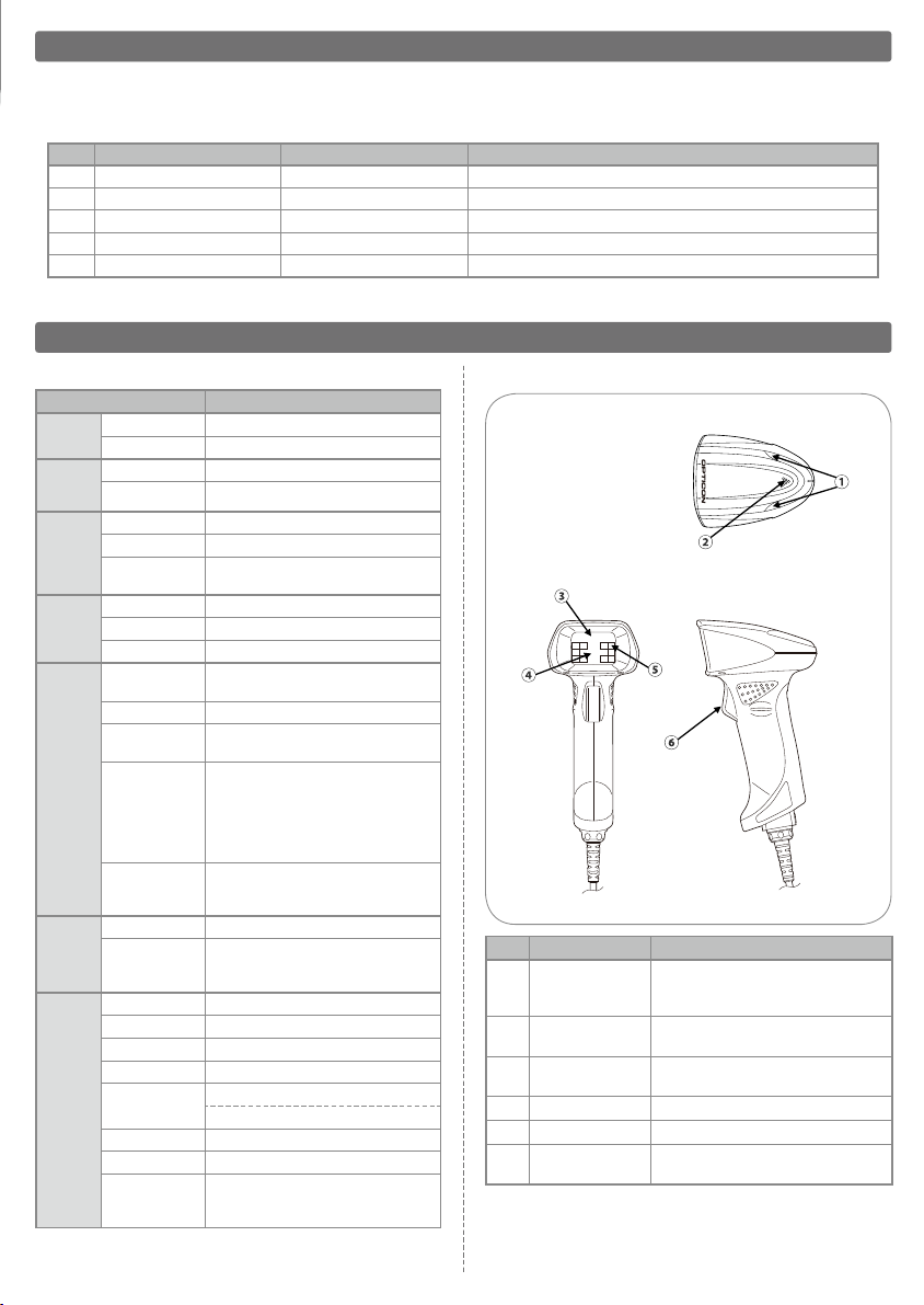
Detailed View
No. Part Function
Status LED
①
Buzzer Hole
②
Aiming Laser
③
Receiving Lens Receives images through the lens.
④
Floodlighting Illuminates barcodes in the dark.
⑤
Trigger Switch
⑥
Turns bl ue when th e OPI-2101
regi sters a su ccessfu l rea d and red
when it fails.
Buzz er s ounds throu gh the buzze r
hole.
Il lumi nate s lase r be am aim ing at
symbologies.
Starts scanning/decoding barcodes.
Page 3

DOS/V
HOST
DOS/V
SCAN
D
O
S
/
V
K
E
Y
Interface
The OPI-2101 supports RS-232C, USB, and Wedge interfaces.
RS-232C Interface
□
How to connect
❶
Connect the 9-pin D-Sub female connector to the
serial port of the host computer.
❷
Insert the AC/DC adaptor plug into the DC jack of the
interface cable. Start up the host computer.
OPI-2101
Connect to
D-Sub9 Pin (Female)
Connect to AC/DC Adapter
• Japanes e Kanji data or im ages can be trans mitted via RS232C i nterface.
Memo
the Host
USB-HI D ( Huma n I nter face Devi ce) and USB-V CP
(Virtual Communication Port) are available.
□
How t o Install a USB Driver for USB-VCP
To con nect th e O PI-21 01 to a h ost usi ng a d edica ted USB
cable, you must firs t install a de dicated USB d river on the host.
If the driver CD is no t inc luded in the b ox, v isit the O pticon
web site (w ww.o ptic on.c om) sec tion “Ser vice & Sup port” |
“
Downlo ad Software” to do wnload the a vailable dr iver.
Oper ating Enviro nments
OS : W indows 2000 / XP / VIST A
Hard D isk Space : 10MB or mor e
Memory : 64MB or m ore is reco mmended
Commun ication Port : USB1.1 o r higher
□
USB D river for US B-HID
The dr iver for US B-HID is in serted in t he operatin g system an d
does n ot require f urther inst allation.
• This interface d oes not req uire an AC/ DC adaptor.
• Japan ese Kanji da ta or images can be tran smitted via USB-VCP
interf ace not via USB-HID int erface.
• This interfac e nee d to be connect ed to a high-pow ered bus
(500 m A max.) USB terminal.
• W hen usi ng the USB-HID interfa ce do not c arry ou t scann ing
or keyboard operation before the ho st compu ter's op erating
system is fully ac tivated.
USB Interface
Wedge Interface
With Wed ge Interface, it is selectable to connect or disconnect the keyb oard.
□
How to connect
❶
Connect the Wedge Interface cable to the branch
■
Without keyboard
cable. Connect the 6-pin mini-DIN female connector
(marked as "DOS/V SCAN") to the 6-pin mini-DIN male
connector of the interface cable.
❷
Connect the 6-pin mini-DIN male connector (marked
as "DOS/V HOST") to the keyboard connector of the
host computer and connect the 6-pin mini-DIN female
connector (marked as "DOS/V KEY") to the keyboard.
❸
Insert the AC/DC adaptor plug into the DC jack of
the interface cable. Start up the host computer.
■
With keyboard
serial command : KL
serial command : KM
OPI-2101
Connect to AC/DC Adapter
Mini-Din 6 Pin (Female)
Connect to
the Keyboard
Mini-Din 6 Pin (Female)
Connect to Wedge branch cable
Mini-Din 6 Pin (Male)
Wedge branch cable
Connect to
the Host
Mini-Din 6 Pin (Male)
• Do not us e the k eyboard d uring dat a transmi ssion to the
host c omputer or d ata transmi ssion may f ail.
Memo
• Do no t tur n the ad apt er ON or O FF wh ile us ing t he
keyboa rd. Doing so may cause a malfuncti on.
• Japan ese Kanji data o r images cannot be transm itted via
this W edge interfa ce.
• Do not car ry o ut any scan ning or key boar d o perat ion
bef ore the h ost com puterʼs ope ratin g syste m is full y
activa ted.
Page 4

Auto Trigger Setting
(Di sable d by defau lt)
In auto trigger mode, the scanner captures a barcode image using the ambient light. The scanner detects the dark pixels
and light pixels in the detection area. The scanning operation stops within the designated duration.
■
Enable Auto Trigger
serial command : +I
■
Disable Auto Trigger
serial command : +F
Laser Beam Aiming Guide Setting
(Di sable d by defau lt)
In order to assist for clear recognition of the scanning area, the floodlight of this product using white LEDs is guided by a
red laser aiming spot.
■
Enable Laser beam aiming guide
serial command : D3D
■
Disable Laser beam aiming guide
serial command : D3E
Universal AC/DC Adapter
■
Basic Specifications for Universal AC/DC Adapter
Parame ter Specif ications
Physical
Features
Size
Cable Length 1.8m
(H)75 x (W)47.5 x (D)28mm (excluding boss)
Colour Black
Input
Output
Enviro nmental
Specif ication
Power Voltage
Supply Current
Power Voltage
Maximu m Current
Operating Temp.
Operating Humidity
Storage Temp.
Storage Humidity
AC 90V to 265V
500mA Max
5.7V to 6.3V
2A Max
0 to 40 deg. C
25 to 85% (non-condensing)
-20 to 60 deg. C
20 to 90% (non-condensing)
■
Plug Connectors
For
Europe
■
Universal AC/DC Adapter
For
the UK
For
Australia
φ
4.0±0.05
For the
US and Japan
φ
1.7±0.05
Contact
Please contact OPTICON or your local dealer.
The Netherlands
U.S.A.
France
Germany
Italy
Spain
More product details, additional support, and configuration options (from the Universal Menu Book) are available at www.opticon.com.
Opticon Sensors Europe B.V.
tel: +31 (0)23-5692700
Opticon Inc.
tel: 800-636-0090
Opticon S.A.S.
tel: +33 (0)1-41461260
Opticon Sensoren GmbH
tel: +49 (0)6074-91890-0
Opticon s.r.l.
tel: +39 (0)051-6321800
Opticon Sensores S.L.
tel: +34 (0)902-747469
email: sales@opticon.com
/
email: opticon@opticonUSA.com
/
email: opticon@opticon.fr
/
email: sales.de@opticon.com
/
email: opticon@opticonitalia.it
/
email: info@opticon.es
/
Sweden
United Kingdom
Taiwan
China
Australia
Brazil
Opticon Sensors Nordic AB
tel: +46 (0)8-58548560
Opticon Limited
tel: +44 (0)1582-635100
Opticon Far Eastern Ltd.
tel: +886 2-27597444 / email: taiwan@opticon.com
Opticon Sensors Europe B.V., Shanghai Representative Oce
tel: +86 21-64480881
Opticon Sensors Pty. Ltd.
tel: +61 (0)2-43402666
Opticon Sensors Europe B.V., Latin American Oce
tel: +55 11-5081 2088
email: henrik@opticon-sensors.se
/
email: sales@opticon.co.uk
/
email: china@opticon.com
/
email: sales@opticon.com.au
/
email: sales.la@opticon.com
/
OPI21019062-0 -00
 Loading...