

Page 1

Contents
Introduction............................. 0-1
Dropside ................................. 1-1
Double cab ............................. 2-1
Auxiliary heating system......... 3-1
Page 2
0-1 Introduction
Introduction
This manual contains supplementary
information regarding the operation
and use of specific conversions
available for your vehicle. This
manual should be used in conjunction
with the vehicle Owner's Manual.
You must always comply with the
specific laws of the country that you
are travelling through. These laws
may differ from the information in this
manual.
When instructed to consult a
workshop, we recommend that you
consult an Opel Service Partner. All
Opel Service Partners offer first-class
service at reasonable prices.
You will receive quick, reliable and
individual service.
Experienced mechanics, trained by
Opel, work according to specific Opel
instructions.
This manual should always be kept
together with the Owner’s Manual
and Service Booklet in the vehicle:
Ready to hand in the glove
compartment.
Make use of this manual:
Yellow arrows in the illustrations
serve as points of reference or
indicate some action to be
performed.
Black arrows in the illustrations
indicate a reaction or a second
action to be performed.
Directional data, e.g. left or right, or
front or back, in the descriptions
always relates to the direction of
travel.
Page references are indicated with
3. 3 means “see page”.
9 Warning, Caution
Vehicle passengers should be
informed accordingly.
9 Warning
Text marked 9 Warning provides
information on risk of accident or
injury. Disregard of these
instructions may result in injuries.
Caution
Text marked Caution provides
information on possible damage to
the vehicle. Disregard of these
instructions may lead to vehicle
damage.
Page 3
1-1Dropside
Dropside
Loading ................................. 1-1
Sideboards and tailboard ...... 1-2
Using the step....................... 1-2
Underfloor storage
compartments 3 ................. 1-3
Cleaning................................ 1-4
Owner’s checks..................... 1-4
Technical data ...................... 1-5
Loading1)
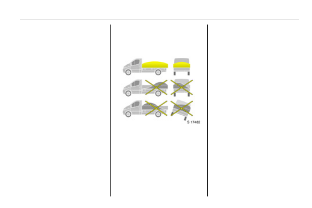
The dropside body is not designed for
carrying people or unsuitable/unsafe
materials.
Ensure the vehicle tailboard and
sideboards are securely closed
before loading.
Load vehicle evenly, distributing
the load across the body.
Secure any solid loads with
additional lashing equipment.
1)
Observe the national regulations on
securing loads.
Place loads onto the dropside body
from the minimum practicable
height. Do not drop loads onto the
body floor.
Do not overload the dropside body.
Ensure the load will not fall out or
endanger other road users.
Do not leave load deposits on
public roads or footpaths.
Do not drive with the tailboard or
sideboards down.
Page 4
1-2 Dropside
Sideboards and
tailboard
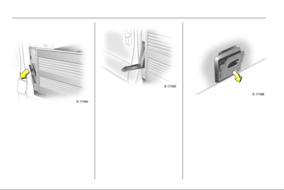
To lower the sideboard:
Release both sideboard levers by
pulling the lever outwards.
Pull the lever down until it contacts
the body and lower the sideboard
carefully.
To lower the tailboard:
Release both tailboard levers.
Lower the tailboard carefully.
To raise:
Raise the sideboard or tailboard and
push firmly against the body. Push
the lever up into its recess until an
audible click is heard. Check the
sideboard and the tailboard are
secure.
Using the step
Lowering:
With the tailboard down, swing the
step plate down to a horizontal
position.
Stowing:
Swing the step plate up into the
vertical position against the mounting
bracket.
Page 5
1-3Dropside
Lashing points
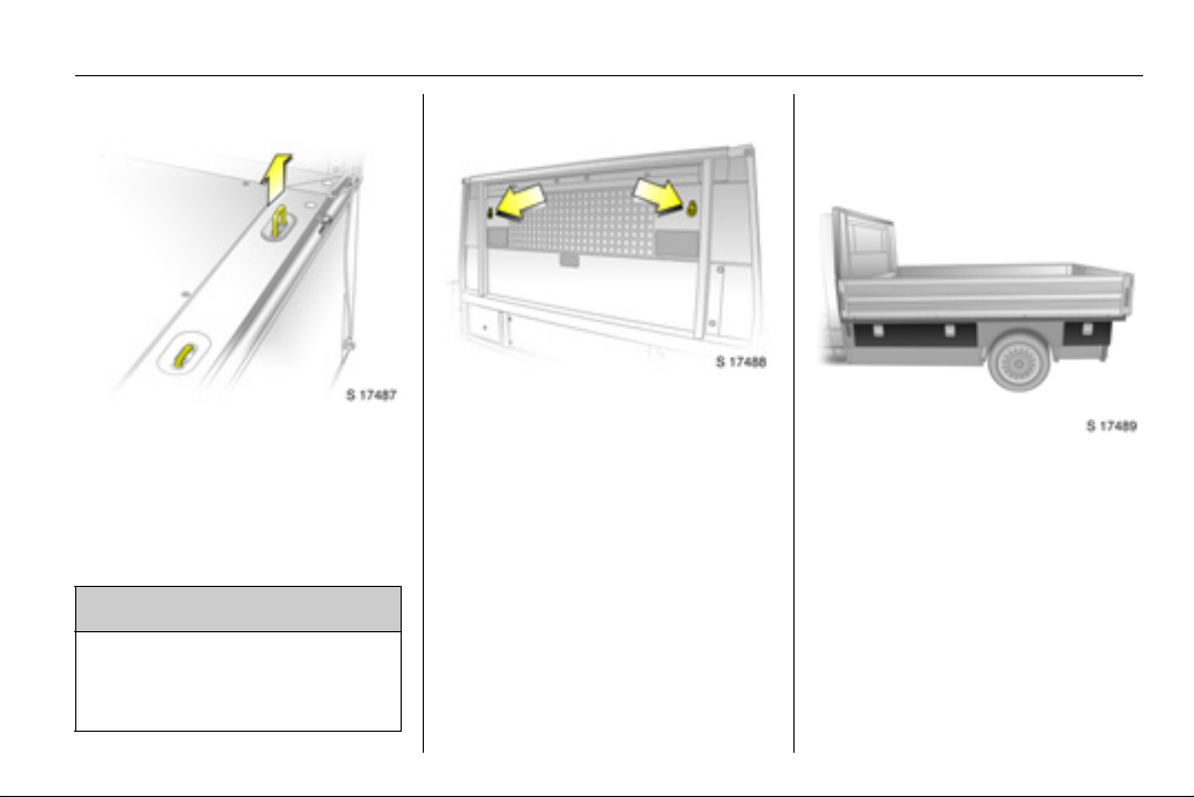
Pull up the lashing eyes as required.
Secure heavy objects with lashing
straps attached to the lashing points.
If heavy loads slip when the vehicle is
braked heavily or driven around a
bend, the handling of the vehicle may
change.
9 Warning
When loading heavy or bulky
items, the lashing point eyes must
be flush with the body floor to
avoid causing any damage.
The two additional lashing points on
the bulkhead should also be used to
secure the load whenever possible.
Observe the safety labels on the
bulkhead to avoid overloading.
Underfloor storage
compartments 3
Certain models feature five lockable
underfloor storage compartments.
For security, these can be locked with
the key provided.
Page 6

1-4 Dropside
To open, pull latch and lower flap.
Upon closing, ensure the flap is
pushed firmly until an audible click is
heard.
Cleaning
Dirt or mud which remains dry on the
body may become abrasive and can
damage paint, seals, locks and
hinges.
Clean the following parts of the
dropside if contaminated with dirt:
Sideboard and tailboard locks,
latches and hinges.
After cleaning, check and lubricate
the latches and hinges as necessary.
Owner’s checks
In conjunction with the Service items,
the following checks are additionally
required.
Every week:
Tailboard/sideboard latches and
hinges: check operation.
Every month:
Bolts and nuts of sub-frame
mounting: check tightening torque.
A workshop will also be able to advise
you if additional service operations
are recommended, depending on the
specific operating conditions of your
vehicle.
These operations can be performed
at the same time and intervals as a
vehicle Service.
Page 7
1-5Dropside
Technical data
The technical data is determined in
accordance with European
Community standards. We reserve
the right to make modifications.
Specifications in the vehicle
documents always have priority over
those stated here.
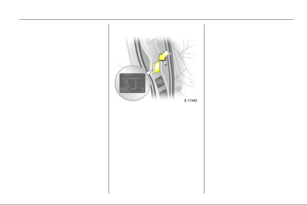
Vehicle identification
The Gross Vehicle Weight and Gross
Train Weight can be found on the
vehicle identification plate, which is
located on the right-hand door pillar.
Page 8

1-6 Dropside
Vehicle weights (approx. kg)
Model Wheelbase Engine GVW Kerb weight
Dropside Long M9R
G9U
F4R
1)
Without driver, base model including all fluids (tank 90% full).
2)
Kerb weight increases on models fitted with bad road equipment package - refer to VIN plate.
3060
3060-3065
2990
1990
2038-2051
1924
1)2)
Dimensions (approx. mm)
Model Dropside
Length 5350
Width
with exterior mirrors
Height (unladen) 2000
Wheelbase 3498
Track width
Front
Rear
1980
2206
1615
1630
Payload
1070
1014-1022
1066
Page 9

2-1Double cab
Double cab
Introduction ............................. 2-1
Technical data ........................ 2-3
Introduction
The double cab uses an additional
rear bench seat to provide increased
seating for up to six people.The rear
loadspace area is separated from the
passenger compartment by a
partition wall.
Page 10
2-2 Double cab
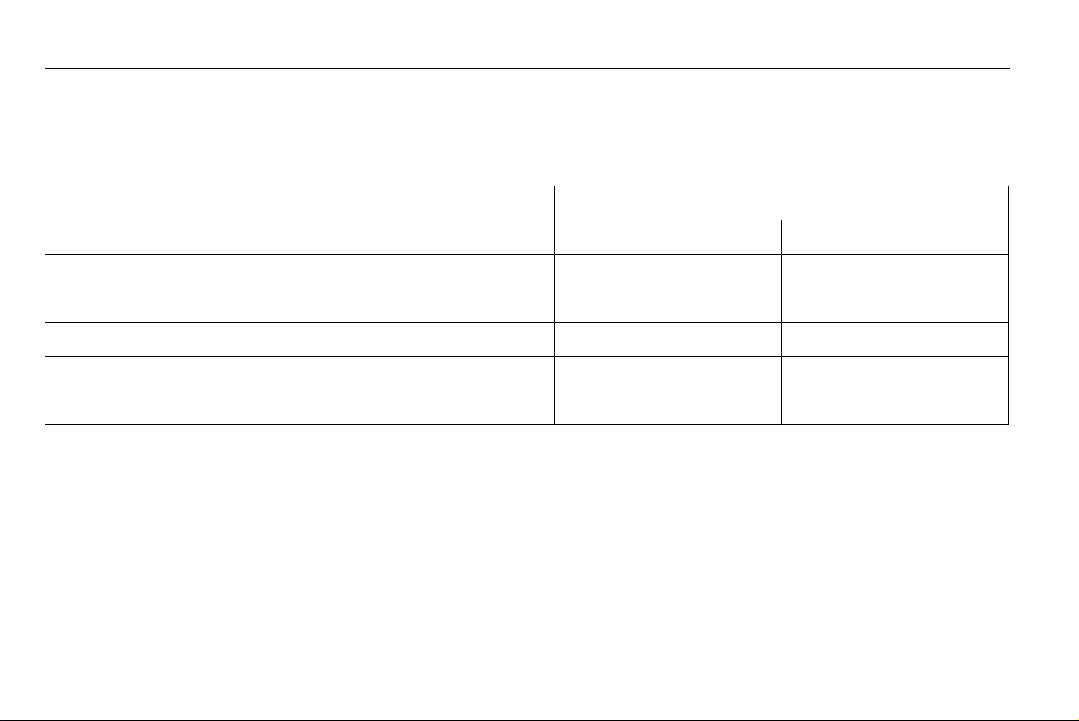
Child restraint systems 3
The table shows permissible locations for installing a child restraint system. Refer to Owner’s Manual for further information.
Rear seats
Group, weight and age class Facing
direction
0: up to 10 kg or approx. 10 months
Rearward XX
0+: up to 13 kg or approx. 2 years
I: 9 to 18 kg or approx. 8 months - 4 years Forward XX
II: 15 to 25 kg or approx. 3 - 7 years
Forward XX
III: 22 to 36 kg or approx. 6 - 12 years
X = Seat position not suitable for children of this mass group.
Outer Centre
Rear bench seat
Page 11
2-3Double cab
Technical data
The technical data is determined in
accordance with European
Community standards. We reserve
the right to make modifications.
Specifications in the vehicle
documents always have priority over
those stated here.
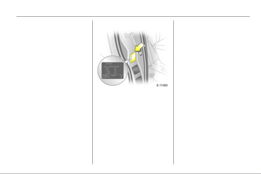
Vehicle identification
The Gross Vehicle Weight and Gross
Train Weight can be found on the
vehicle identification plate, which is
located on the right-hand door pillar.
Page 12

2-4 Double cab
Vehicle weights (approx. kg)
Model Wheelbase Roof Engine GVW
Double cab Short Standard M9R
G9U
F9Q
F4R
Long Standard M9R
G9U
F9Q
F4R
1)
Depending on transmission.
2)
Without driver, base model including all fluids (tank 90% full).
3)
Depending on transmission and optional equipment.
2935-2945
2985-2995
2620-2780
2645-2860
2930-2960
3005-3035
3065
2945
1)
Kerb weight
1804-1853
1852-1902
1560-1569
1835
1840-1889
1887-1937
1776
1835
2)3)
Payload
1092-1131
1093-1133
885-936
860-1025
1041-1120
1068-1148
1314
1110
Page 13

Loadspace dimensions (approx. mm)
Wheelbase Short Long
Roof Standard Standard
Maximum rear door aperture height 1320 1320
Rear door aperture width (at floor) 1390 1390
Maximum load area height 1387 1387
Maximum load area width 1690 1690
Width between wheel arches 1268 1268
Maximum load floor length 1906 2306
Loading height (unladen) 549 542
Sliding side door aperture width 1000 1000
Sliding side door aperture height 1285 1285
2-5Double cab
Page 14

3-1 Auxiliary heating system
Auxiliary heating
system
Coolant heater........................ 3-1
Manual control unit ................. 3-2
Remote control unit 3............. 3-3
Coolant heater
The Eberspächer engineindependent, fuel-powered coolant
heater, located under the vehicle,
provides rapid heating of the engine
coolant to enable heating of the
vehicle interior without running the
engine. It will also help the engine to
reach operational temperature more
quickly.
The heater can be programmed to
start at a specific time or switched on
for immediate use.
The heater is controlled with a control
unit on the instrument panel or with a
radio remote control 3.
Before switching the heater on or
programming heating operation, turn
the temperature switch on the heating
and ventilation system to the red
zone and set fan to position 1.
When the heater unit is on, fuel
consumption increases. Switch off
the unit whenever it is not required.
The heater will cease to operate if the
vehicle fuel level drops too low.
The heater unit stops automatically
after a maximum 2 hours of
continuous use. The fuel supply to
the heater is cut-off.
To ensure efficient performance, the
heater must be operated briefly once
a month.
If the heater does not start when
switched on, switch it off and back on
again. If it still does not start, seek the
assistance of a workshop.
9 Warning
Do not operate the heater in an
enclosed space and ensure it is
switched off when refuelling!
The additional exhaust pipe on
the right-hand side of the vehicle
becomes very hot during heater
operation.
Refer to the supplied instructions for
the heater unit for further information.
Page 15
3-2Auxiliary heating system
Control unit
Manual control unit
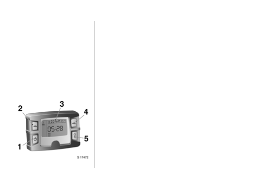
The heater control unit is located on
the instrument panel.
The heater unit can be switched on
for immediate use (one-off mode) and
the timer function 3 (programmed
mode) set using the four buttons on
the control unit.
The control unit can be used to
programme up to 3 preset departure
times 3, either during one day or over
one week.
1 Activation button
Switches timer on/off.
Switches between display
items.
2 Back button
Selects display options and
adjusts values.
3 Display
Display of settings and status.
4 Next button
Selects display options and
adjusts values.
5 OK button
Selects flashing items and
confirms inputs.
Switching heater on for
immediate use
Activate the control unit by pressing
activation button 1 until the menu and
the time/temperature 3 appears in
the display.
Press the back button 2 or next
button 4 until the heater symbol Y
flashes in the display and press OK
button 5 to select heating. The heater
symbol Y appears in the display.
The heating duration, e.g. L 30,
then flashes in the display.
If necessary, change the value and
press OK to confirm the heating
duration for this use of the heater
only. The value can be set from 10 to
120 minutes and continuous
operation can also be selected.
Switching heater off
With control unit activated, press the
back or next button until Y flashes in
the display and press OK; the
Y symbol extinguishes.
The display disappears after a brief
delay when the heater is switched off,
the vehicle lighting is switched off or if
no input is made.
Setting heating level
The heating level can be changed
between ECO and HIGH.
Page 16
3-3 Auxiliary heating system
With control unit activated, press the
back or next button until the heating
level arrow flashes in the display and
press OK. ECO or HIGH flashes in
the display. If necessary, change the
heating level and press OK.
The heating level arrow also appears
in the display when set.
Programming departure
times 3
With control unit activated, press the
back or next button until the P symbol
flashes in the display and press OK.
Preset memory location 1, 2 or 3
flashes.
Select desired program memory
location and press OK.
Weekday flashes.
Select weekday and press OK.
Hours flash.
Change hours and press OK.
Minutes flash.
Change minutes and press OK.
The symbol for heating Y,
ventilation x 3, or additional unit
3 flashes.
Select symbol Y and press OK.
The heating duration flashes.
If necessary, change the value and
press OK.
The next preset memory location to
be activated is underlined and the
corresponding weekday is also
displayed.
Repeat procedure to programme the
other preset memory locations.
Press activation button again during
procedure to exit without storing
programme adjustments.
A
Deleting departure times
Follow the steps for programming
departure times, until heating
symbol Y flashes.
Press the back or next button until
oFF appears in the display and press
OK to delete the programmed
departure times.
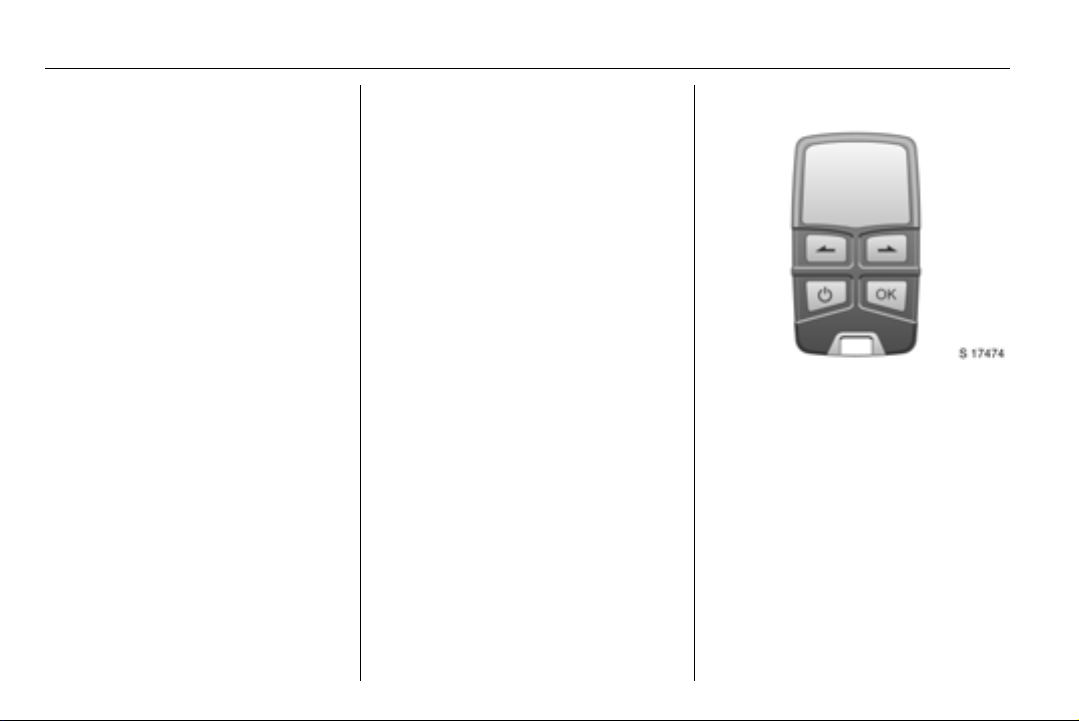
Remote control unit 3
D
Operation of the remote control is
similar to the manual control unit.
A temperature sensor is included, so
the time the heater begins to operate
is calculated depending on the
ambient temperature and the
selected heating level (ECO or
HIGH). The heater may switch on
automatically between 5 and 60
minutes before the preset departure
time, and switches off 5 minutes after
the programmed departure time.
Page 17
3-4Auxiliary heating system
To activate the remote control, press
activation button and release when
the menu appears in the display. The
signal indicator then appears briefly
in the display, followed by SENd
(display lighting switches off briefly),
then the temperature.
The remote control has a maximum
range of 1 000 metres. The range will
reduce due to environmental
conditions.
Press and hold the activation button
to switch off and prevent inadvertent
operation.
9 Warning
Always ensure the remote control
unit, as well as the heater is
switched off when refuelling!
Refer to the supplied instructions for
the heater and the remote control unit
for further information.
Battery replacement
Replace the battery (CR2430 or
equivalent) when the range of the
remote starts to become reduced or
when the battery charge symbol
indicates a weak battery. Change
immediately when the symbol flashes
in the display.
Open the rear cover using a coin and
replace battery. Ensure the new
batteries are installed correctly, with
the positive (+) sides facing the
positive terminals. Replace cover.
Dispose of old batteries in
accordance with environmental
regulations.
Resetting
If the power supply is interrupted or
the battery voltage is too low, the
current weekday, time and the default
heating duration for one-off mode and
all programmed departure times are
lost: The unit will need to be reset.
To reset weekday, time and heating
duration: activate the unit. The
weekday, time and clock symbol Ö
should appear.
Press the back or next button until the
clock symbol Ö flashes in the display
and press OK.
Weekday flashes.
Select weekday and press OK.
Hours flash.
Change hours and press OK.
Minutes flash.
Change minutes and press OK.
The heating duration flashes.
If necessary, change the value and
press OK.
 Loading...