

Page 1

Opel Blazer
Operation, Safety, Maintenance
Page 2

Your Blazer
Developed to the latest findings of automobile research, it offers
technical sophistication and exceptional comfort. Particular emphasis
was placed on using environmentally sound, recyclable materials,
throughout the design process. Your Blazer represents an ideal
synthesis of advanced technology, outstanding safety, environmental
compatibilty and economy in operation.
Your Blazer may use Premium, Premix or Unleaded fuel.
It now lies with you to drive your Blazer safety and to see it performs perfectly.
Make use of this owner’s manual:
It gives you all the necessary information
It has an index to help you find what you want.
It will familiarize you with the sophisticated technology.
It will increase you pleasure in your Blazer.
It will help you to handle your vehicle expertly.
The Owner’s Manual should always be kept in the vehicle:
ready to hand in the glove compartment.
Care and maintenance as detailed in the Owners Manual and
Maintenance Booklet ensure safe vehicle operation and
maintain the value of your car.
We wish you many hours of pleasurable driving
Your Opel team
Page 3
Opel Blazer Owner’s Manual
How to Use this Manual ................................................................................................... ii
Important Safety Precautions ........................................................................................... iii
Instrumentation and Controls ......................................................................................... 1-1
Seats and Safety Belts .................................................................................................... 2-1
Starting and Operating Instructions ................................................................................ 3-1
Service and Maintenance ................................................................................................ 4-1
Problems on the Road .................................................................................................... 5-1
Index ............................................................................................................................. 6-1
i
Page 4
Important Notes About
this Manual
This manual should be considered a permanent part
of the vehicle. Keep it with the vehicle when sold, to
provide the next owner with important operating, safety
and maintenance information.
How to Use this Manual
Use this manual to learn about the features of your new
vehicle and how they operate.
CAUTIONS and NOTICES alert you to conditions that
may result in injury, or that may damage your vehicle.
All information, illustration and specifications in this
manual are based on the latest product information
available at the time of printing. We reserve the right
to make changes in the product without further notice.
The illustration throughout the manual are typical and
are not intended to exact representations of any part of
your vehicle. Please be aware that the vehicle you
purchase may not be equipped with each option that is
explained in this manual.
When it comes to service, keep in mind that your
dealer knows your vehicle best and is commited to your
complete satisfaction. Your dealer invites you to return
for all of your service need both during and after the
warranty period. Should you have any concern that has
not been handled to your satisfaction, follow the steps
outlined in the Warranty and Owner Assistance
Information booklet.
CAUTION:
These mean there is something that could hurt you or
other people.
NOTICE:
These mean there is something that could damage
your vehicle.
ii
Page 5

Important Safety Precautions
CAUTION:
• Be sure the shift lever is in REVERSE (R)
and the parking brake is firmly applied
when you leave your vehicle.
• Idling the engine inside an enclosed area
such as garage, and/or with the air
conditioner’s fan off, may allow dangerous
exhaust fumes into your vehicle.
• Engine exhaust can kill. If you suspect
exhaus is coming into your vehicle, have it
fixed immediately.
CAUTION: (Continued)
CAUTION: (Continued)
• Always wear your safety belt. Be sure it is
adjusted properly at all times.
• Have your brakes checked immediately if
the warning lights stays on.
• When you are going down a steep hill, use a
lower shift range, along with the brakes, to
control the vehicle’s speed.
• Exercise extreme caution around the
electric engine fan. It sometimes starts by
itself, even when the engine is not running.
• When you open the fuel filler cap, open it
slightly at first to release the pressure inside the
tank, then turn it all the way.
iii
Page 6
NOTICE:
• If any warning light on the instrument
panel illuminates while you are driving,
immediately park your vehicle in a safe
place, and follow the instructions in
this manual.
• If the engine stalls while you are driving,
stop and park your vehicle in a safe place.
Without the engine running, the
power-assisted brake and steering systems
will not work properly, and braking and
steering will require substansial effort.
• Do not drive through deep puddles. If
water enters into an air inlet, it might
damage the engine. If you must drive
thriugh a puddle, drive carefully so as not
to allow the water to splash against the
underbody of the vehicle.
NOTICE: (Continued)
NOTICE: (Continued)
• After going through a car wash or driving
through a puddle, the brakes may not work
well. Apply light pedal pressure until the
brakes work normally.
• Do not put paper or flammable items into
an ashtray. They may catch the fire from a
cigarette. Do not carry combustible
materials, such as gasoline, in the rear area.
• Additional equipment, such as cellular
telephone, may interfere with the operation
of your vehicle’s engine, radio or other
electronic systems and even damage them.
Please consult an authorized dealer before
installing electronic equipment.
iv
Page 7

NOTES
v
Page 8

NOTES
vi
Page 9
Section 1 Instrumentation and Controls
This section describes the standard and optional features
and controls that may be on your vehicle. Some of the
features and controls may not be included in your
specific model.
Audio System
See the audio system supplement for information on
how to use your audio system and set the clock.
Antenna
The fixec mast antenna is designed to withstand most
car washes without damage. Check periodically to see
that the mast is securely tightened to the fender.
If the mast becomes slightly bent, you can straighten it by
hand. The mast antenna can be replaced if severely bent.
Mast antennas must be kept clean for good performance.
NOTICE:
Added sound euipment – like a mobile
telephone or two-way radio – may interfere with
the operation of your vehicle’s engine, radio or
other systems, and even damage them. Check
with your dealer.
1-1
Page 10
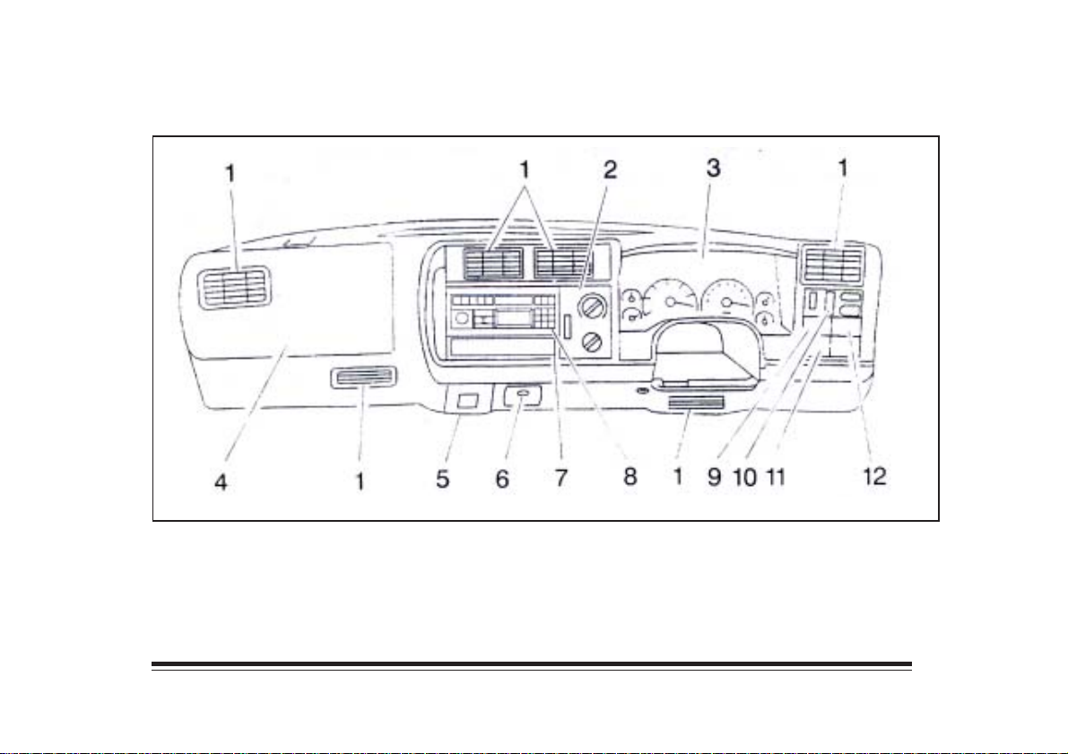
Instrument Panel
1. Air Vents
2. Comfort Controls
3. Instrument Cluster
4. Glove Box
5. Ashtray
6. Cigarette Lighter/Power
Auxiliary Outlets
(Option)
7. Storage Compartment
8. Audio System
9. Rear Window Defogger
10. Lamp Controls
11. Rear Window Washer/
Wiper (Option)
12. Fog Lamps (Option)
1-2
Page 11
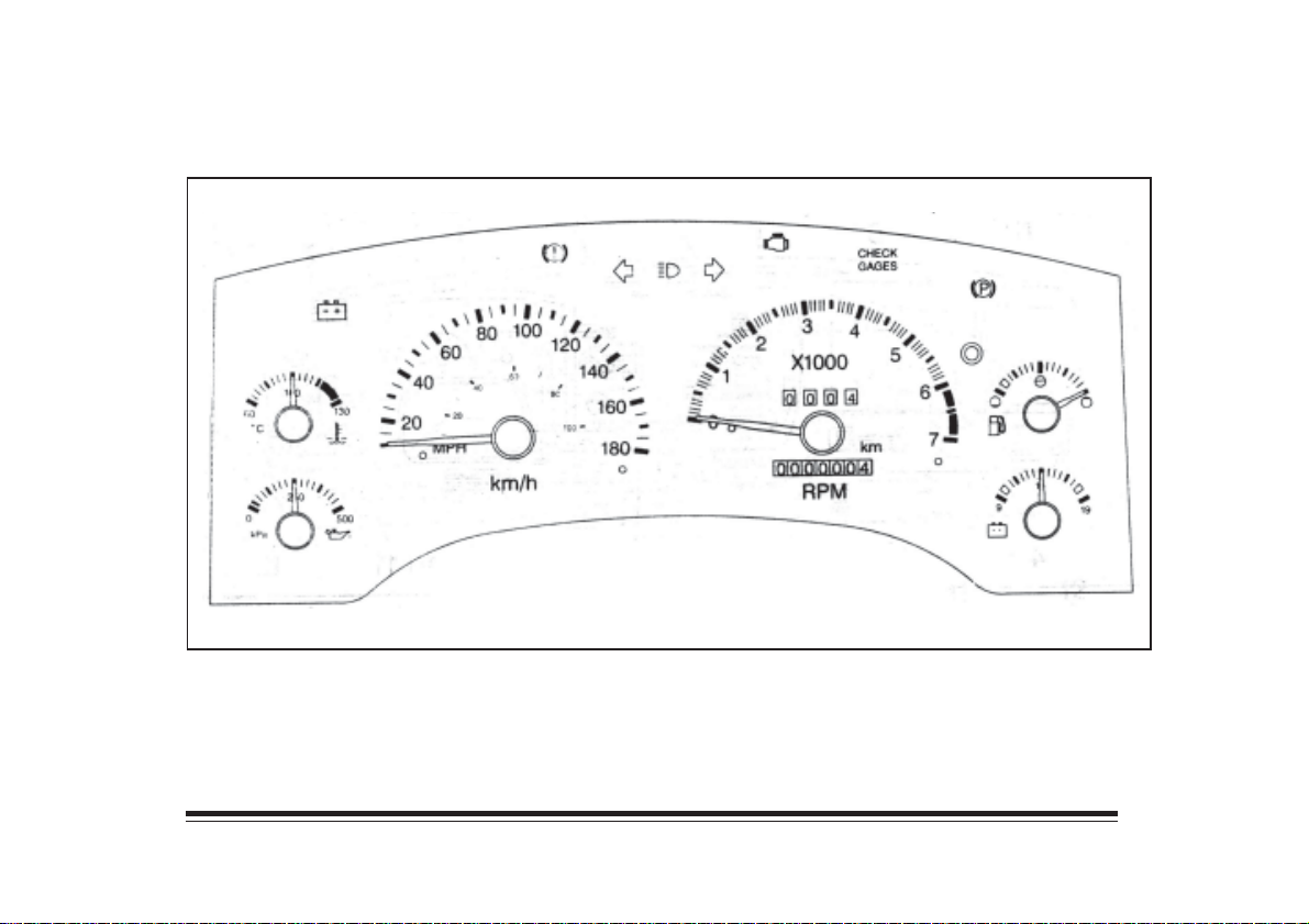
Instrument Panel Cluster
The instrument panel is designed to let you know at a glance how your vehicle is running.
1-3
Page 12
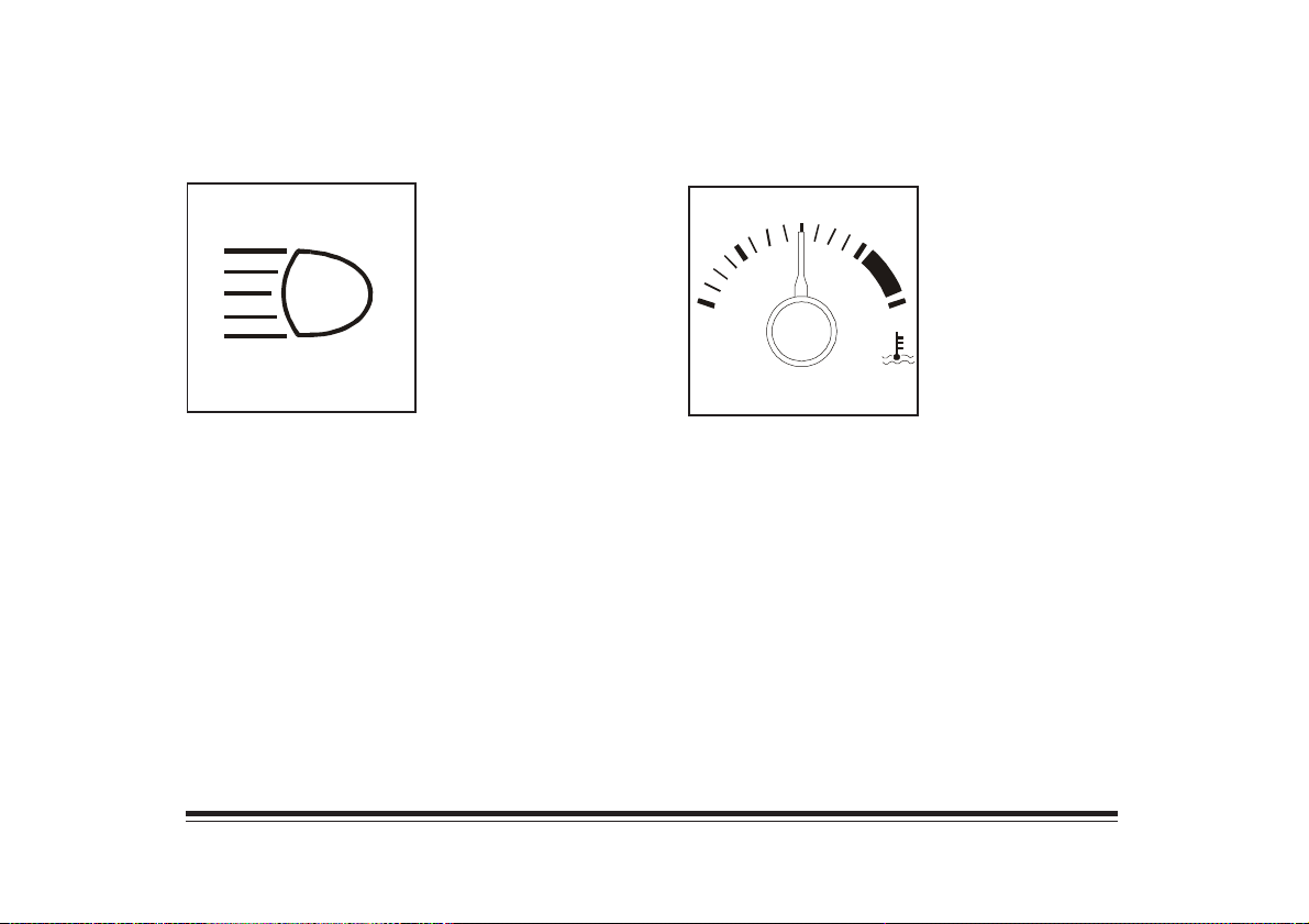
Headlamp High-Beam Indicator
Engine Coolant Temperature Gage
This indicator light comes
on when the headlamps are
set to high beam.
This gage shows the engine
coolant temperature. If the
100
60
o
C
If the engine coolant has overheated, turn the engine off
immediately. See Sections 4 and 5 for more information
on your vehicle’s cooling system.
pointer moves into the red
area, the engine is too hot!
130
1-4
Page 13
Odometer
The odometer shows how far your vehicle has been
driven. The odometer will show silver lines between the
numbers if someone tampers with it.
Trip Odometer
The trip odometer can tell you how far your vehicle has
been driven since you last set the trip odometer to zero.
To set the trip odometer to zero, press the button near
the readout.
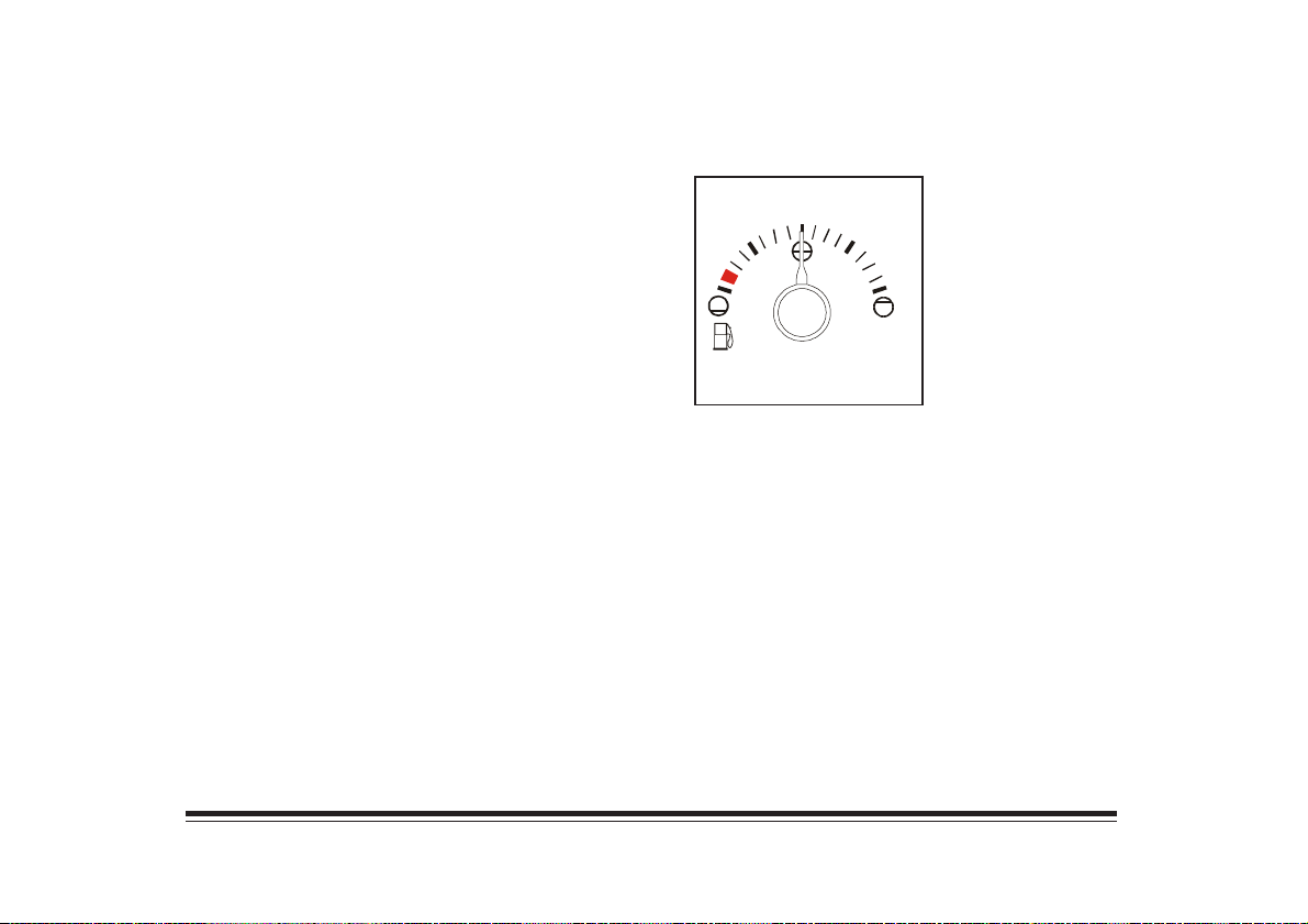
Fuel Gage
The fuel gage shows
how much fuel is in the
fuel tank. The fuel gage
works only when the
ignition switch is on.
Speedometer
The speedometer displays the vehicle’s speed.
Tachometer
The tachometer displays engine speed in thousands of
revolutions per minute (rpm).
NOTICE:
Do not operate the engine with the tachometer in the
red area, or engine damage may occur.
1-5
Page 14
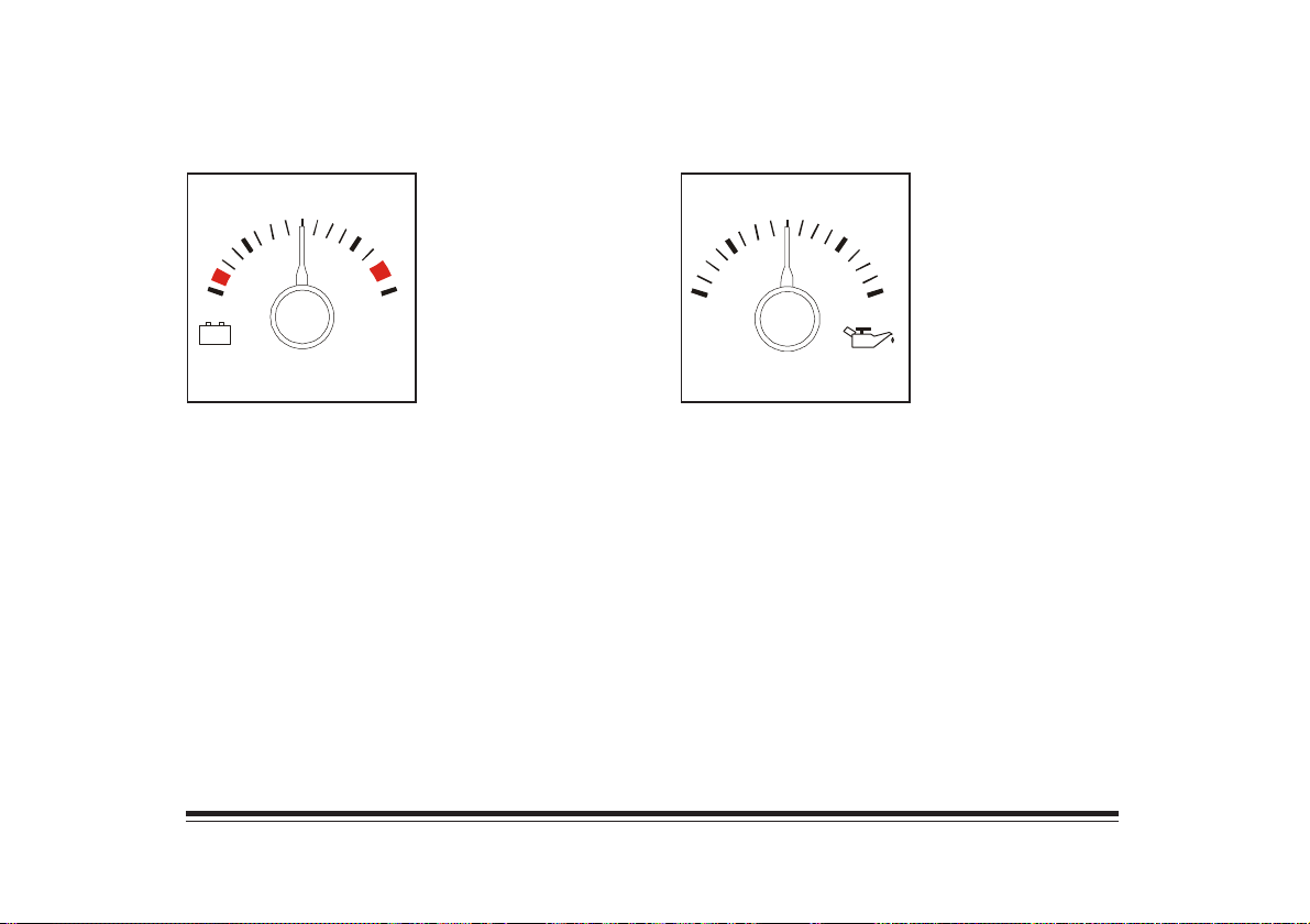
Voltmeter
+
--
14
When the engine is
operating, the voltmeter
indicates the charging
system voltage. When the
ignition is on, but the
engine is not running, it
199
indicates the state of
charge of the battery.
Oil Pressure Gage
250
kPa
The oil pressure gage
indicates the pressure at
which oil is being delivered
to the various parts of the
engine requiring lubrication.
5000
A meter reading continuously in either warning zone
indicates an electrical system malfunction. Have it
checked right away.
Gage readings which are consistently low may indicate
lubrication system and/or engine malfunction.
1-6
Page 15
Warning Lights
Your vehicle has a number of warning lights.
The warning lights go on when teher may be or there is
a problem with one of your vehicle’s functions. Some
warning lights come on briefly when you turn the
ignition key on just to let you know they’re
working properly.
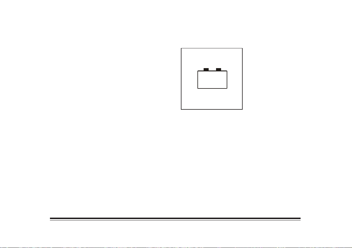
Charging System Light
This light will come on
briefly when you turn on the
ignition, but the engine is
not running, as a check to
show you it is working.
--
+
If it stays on, or comes on while you are driving, you
may have a problem with the electrical charging system.
Have it checked right away.
If you must drive a short distance with the light on, turn
off all accessories, such as the radio and air conditioner.
1-7
Page 16
Brake System Warning Light
Your vehicle has dual brake systems, one for the front
and one for the rear. If one system fails, the other
system can still stop your vehicle.
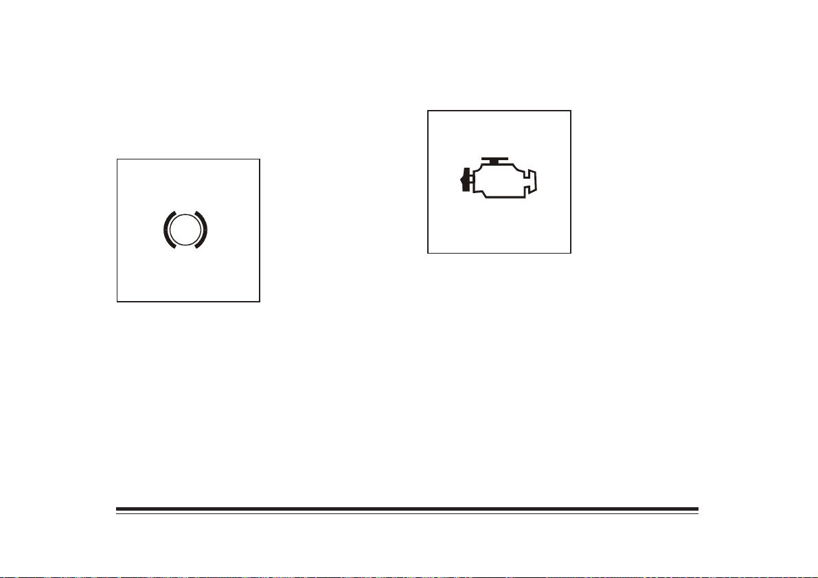
The brake system warning
light should come on as you
start the engine. If it doesn’t
come on, then have it fixed
so it will be ready to warn
!
If the warning light comes on when you are driving,
teher could be a problem with the brake system, the
rear wheel anti-lock system or the parking brake. Have
the brake system inspected right away.
you if there is a problem.
Malfunction Indicator Lamp
The malfunction indicator
lamp monitors the fuel, the
ignition and emission
control systems. The light
whould come on when the
ignition is on, but the
engine is not running, as
a check to show you it is
working properly.
If it does not come on at all, have it fixed right away.
If it stays on, or comes on while you are driving, take
your vehicle in for service.
1-8
Page 17
Safety Belt Reminder Light
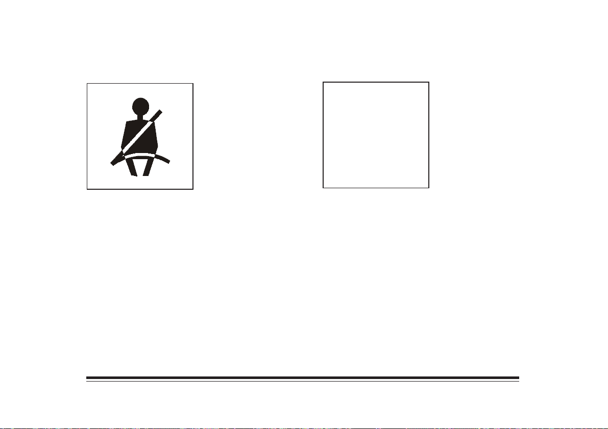
The ligh comes on when
the ignition is turned to
RUN or START as a
reminder to buckle up. A
tone may also sound. See
“Safety Belts” in the Index.
Check Gages Light
CHECK
GAGES
This light should come on
when you start the engine.
If this light comes on and
stays on while you are
driving, check the various
gages to see if they are in
the warning zones.
1-9
Page 18
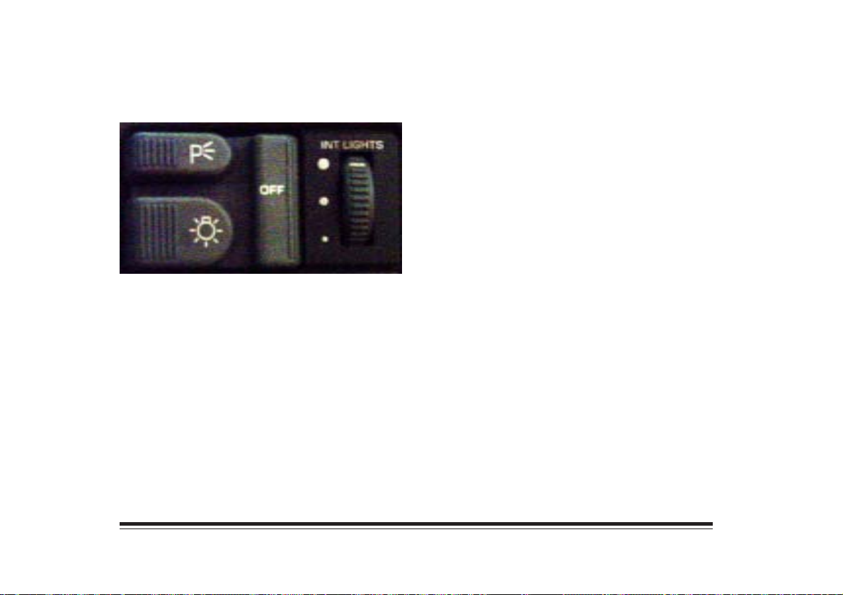
Lamps
The main lamp switch controls the following:
• Headlamps
• Taillamps
• Parking Lamps
• License Lamps
• Sidemarker Lamps
• Instrument Panel Lights
• Interior Courtesy Lamps
Press P to turn on your parking and other operating lamps.
The headlamps will not come on.
Press the master lamp symbol to turn on your
headlamps. The parking and other operating lamps will
also come on.
To change the lamps from low beam to high or high to
low, pull the multifunction lever toward you until you
hear a click. Then release it. When the high beams are on,
an indicator light on the instrument panel will also be on.
Press OFF to turn off the lamps.
Brightness Control
The INT LIGHTS switch controls the brightness of the
instrument panel lights. Rotate the switch all the way up
to turn on the interior lamps.
1-10
Page 19
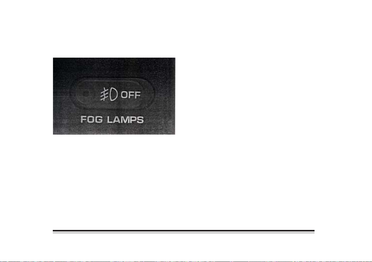
Fog Lamps (Option)
Press the side of the switch with the fog lamp symbol to
turn the fog lamps on. Press OFF to turn them off. A
light will glow in the switch shen to fog lamps are on.
Remember , fog lamps alone will not give off as much
light as your headlamps. Never use your fog lamps in
the darks without turning on your headlamps.
Fog lamps will go off whenever your high-beam
headlamps come on. When the high beams go off, the
fog lamps will come on again.
Dome Lamp
When the doors are opened, the dome lamp will come on.
Use your fog lamps for better vision in foggy or
misty conditions. Your parking lamps or low-beam
headlamps must be on for your fog lamps to work.
Lamps On Reminder (Option)
If you open the driver’s door while leaving the lamps on
and the ignition off, you will hear a warning tone.
1-11
Page 20
Hood Release
Use the hood release handle, located below the lower
right side of the instrument panel, to open the hood.
See “Hood Release” in the Index.
Accessory Power Outlets (Option)
The power outlets are near the lighter.
They can be used to plug in electrical equipment such as a
cellular telephone, portable computers, etc.
NOTICE:
The maximum load of any electrical equipment
should not exceed 20 amps.
Leaving electrical equipment on for extended
preiodes of time can drain your battery.
1-12
Page 21
Ashtrays and Cigarette Lighter
To use the lighter, press it in all the way, and let go.
When it’s ready, it wioll pop back by itself.
NOTICE:
Don’t hold a cigarette lighter in with your hand
while it is heating. If you do, it won’t be able to
back away from the heating element when it’s
ready. That can mae it overload, damaging the
lighter and the heating element.
The front ashtray must be completely pulled out to the
open position before the asthray cover opens and
smoking material can be deposited.
NOTICE:
Don’t put papers and other things that burn into
your ashtray. If you do, cigarettes or other smoking
materials could set them on fire, causing damage.
To remove the front ashtray, lift the release tabs as high
as possible, then remove the tray.
These vehicles have smaller ashtray inside the rear
doors. Press PUSH to turn the ashtray around for use.
1-13
Page 22
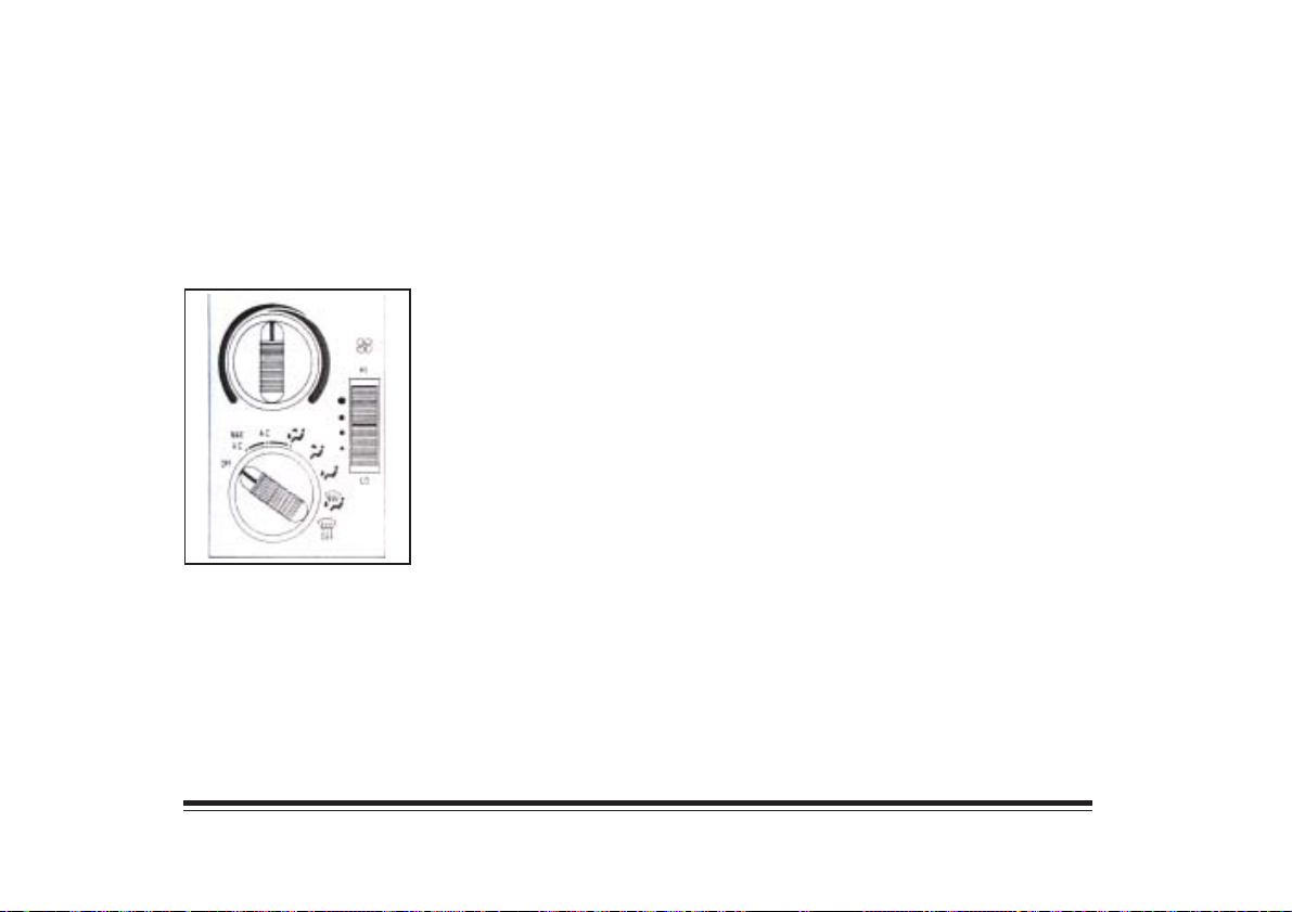
Comfort Controls
With this system, you can control the heating, cooling
and ventilation in your vehicle.
Fan Control
The Switch with the fan symbol changes the fan speed.
To increase the fan speed, move the switch upward. To
decrease the fan speed, move the switch downward.
Heating and Air Conditioning System
Temperature Knob
The upper knob regulates the temperature of the air
coming through the system. Turn the knob clockwise for
warmer air. Turn the knob counterclockwise for cooler air.
Mode Knob
The lower knob allows you to choose the direction of air
delivery.
1-14
Page 23
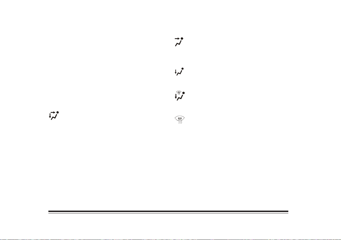
OFF: This setting turns the system off. Some outside
air will still enter the vehicle whenever the vehicle is
moving forward.
MAX A/C (Recirculate): This setting provides
maximum cooling with the least amount of work.
MAX A/C recirculates much of the air inside your
vehicle so it cools quickly.
VENT: This setting directs airflow through
the instrument panel outlets. The air conditioning
compressor is not working when VENT is selected.
HEAT: This setting directs warmed air through
the heater floor outlets and windshield defroster outlets.
A/C: This setting cools the air entering your vehicle
and directs it through the indtrument panel outlets.
BI-LEVEL A/C: Air is delivered through
the heater floor outlets as well as the instrument
panel outlets.
BLEND: Airflow is divided equally between the
heater floor outlets and the windshiels defroster outlets.
DEFROST: This setting directs most air through the
windshield defroster outlets and some through the heater
outlets.
1-15
Page 24
Air Conditioning
On hot days, open the windows long enough to let hot
inside air escape. This reduces the time it takes for your
vehicle to cool down. Then keep your window closed
for the air conditioner to work its best.
For quick cool-down on very hot days, use MAX A/C
with the temperature knob turned counterclockwise.
This setting should be used to keep odors nd/or dust
from entering the vehicle. For normal cooling on hot
days, use A/C with the temperature knob turned
counterclockwise.
On cool but sunny days, use BI-LEVEL A/C to deliver
warm air to the floor and coller air to the instrument
panel outlets.
Ventilation System
For mild outside temperatures, use VENT to direct
outside air through your vehicle. Air flows through the
instrument panel outlets.
Your vehicle’s ventilation system supplies outside air to
the inside of your vehicle when it is moving. When the
vehicle is not moving, you can get outside air to flow
through by selecting any mode and any fan speed. Keep
the air path under the front seats clear of objects. This
helps air to circulate throughout your vehicle.
You will find air outlets in the center and on the sides of
your instrument panel.
You can move the outlets to directs the flow of air, or
close the outlets altogether. When you close an outlet, it
will increase the flow of air coming out of any outlets
that are open.
1-16
Page 25
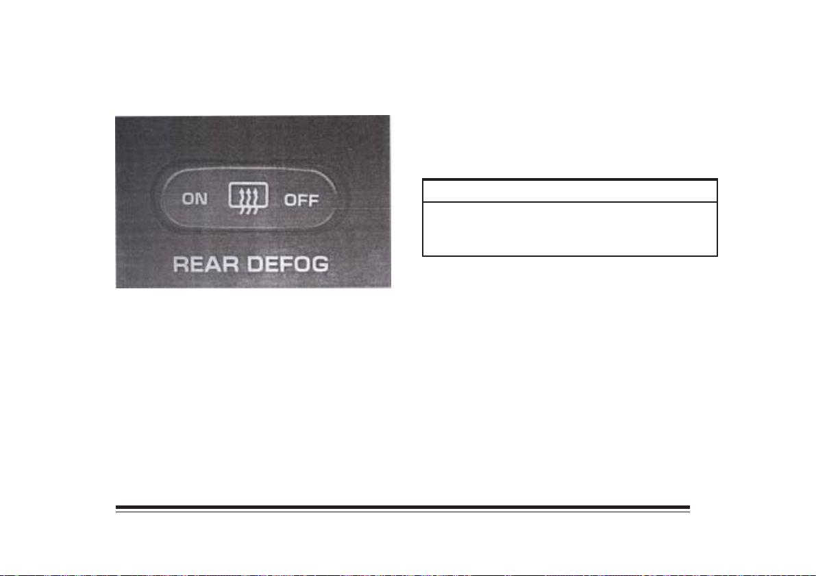
Rear Window Defogger (Option)
Press ON to remove fog from the rear window. An
indicator light will glow. The defogger will turn off
automatically after a few minutes. You can also turn the
defogger off by pressing OFF or by turning the ignition
switch to OFF.
NOTICE:
Don’t use a razor blade or something else sharp
on the inside the rear window. If you do, you
could cut or damage the warming grid.
1-17
Page 26
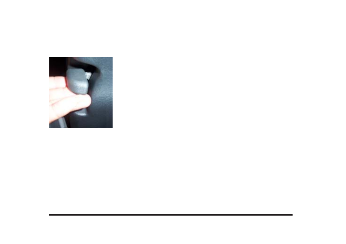
Steering Wheel/Column Controls
Tilt Wheel Lever
You can move the tilt
steering wheel to any one of
several different positions.
To tilt it, hold the steering
wheel and pull the lever
toward you.
Place the wheel where you like it and the release the
lever. It is recomended that you use the upper most
position only for entry and exit.
Horn
Sound the horn by pressing the horn symbols on the
steering wheel.
Hazard Warning Falshers
Press the switch on top the steering column all the
way down to make your turn signal lamps flash on and
off. It works whichever position your ignition key is in,
and even if the key isn’t in.
To turn the flashers off, press the switch down again.
When the flasher is on, your turn signal won’t work.
Ignition Switch
See “Ignition Switch” in the Index.
1-18
Page 27
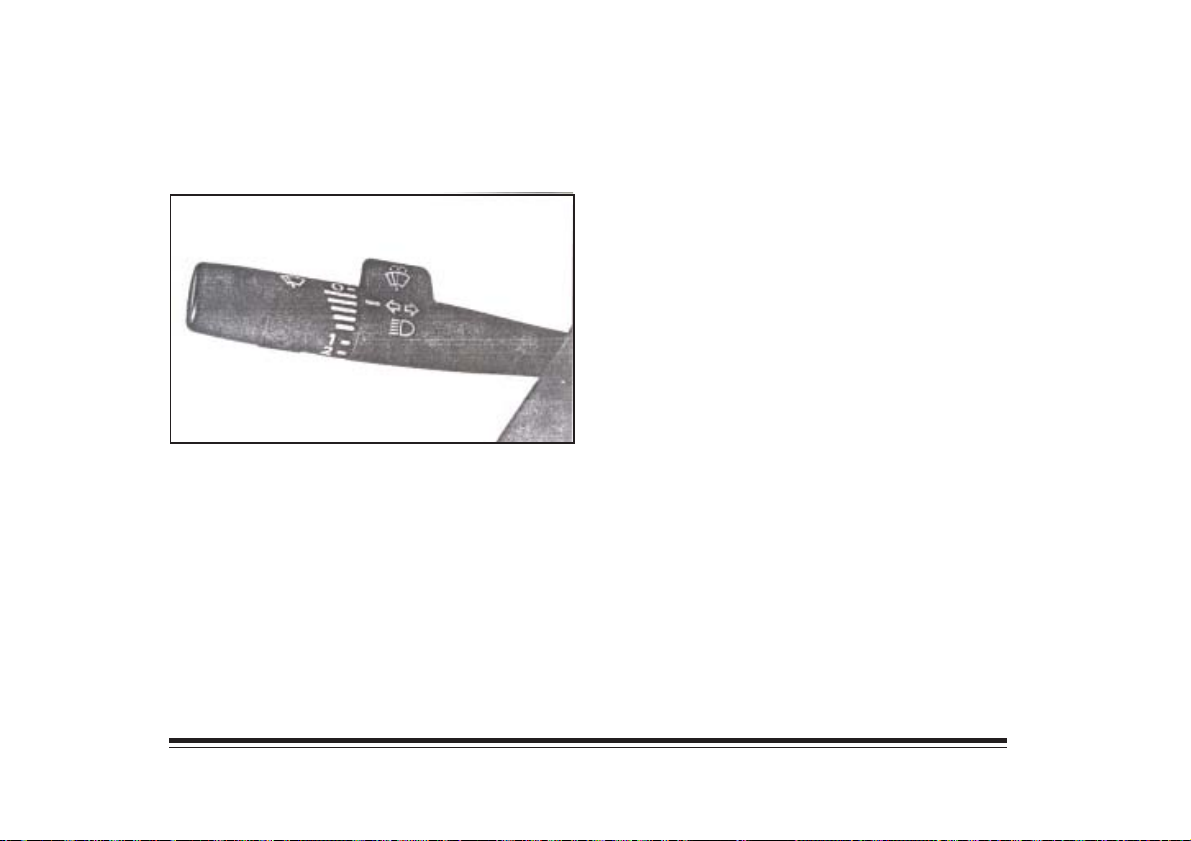
Multifunction Lever Turn and Lane Change Signals
To signal a turn, move the lever all the way up (right) or
down(left). When the turn is over, the lever will return
automatically. To signal a lane change, just raised or
lower the lever until the arrow starts to flash. Hold it
there until you complete your lane change. An arrow in
the instrument cluster will flash in the direction of the
turn or lane change.
Headlamp High/Low Beam Changer
Pull the multifunction lever toward you to select low or
high beam.
Flash-To-Pass Feature
Pull the multifunction lever toward you to operate this
feature.
1-19
Page 28
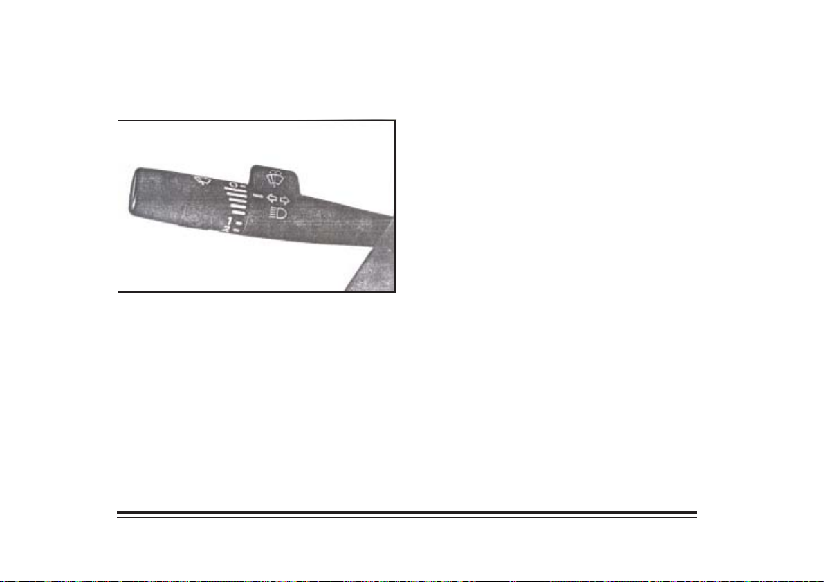
Windshield Wipers
Turn the band with the wiper symbol to circle
for a single wiping cycle. Turn the band back to the
longest bar to turn the wipers off. The rest of the bars
represent different wiper delays. Turn the band to 1 for
continuous low-speed wiping, or to 2 for continuous
high-speed wiping.
Windshield Washer
Press and release the paddle to spray washer fluid on the
windshield. The washer will spray several times and
then stop. The wipers will clear the windows and then
either stop or return to yout preset speed.
1-20
Page 29
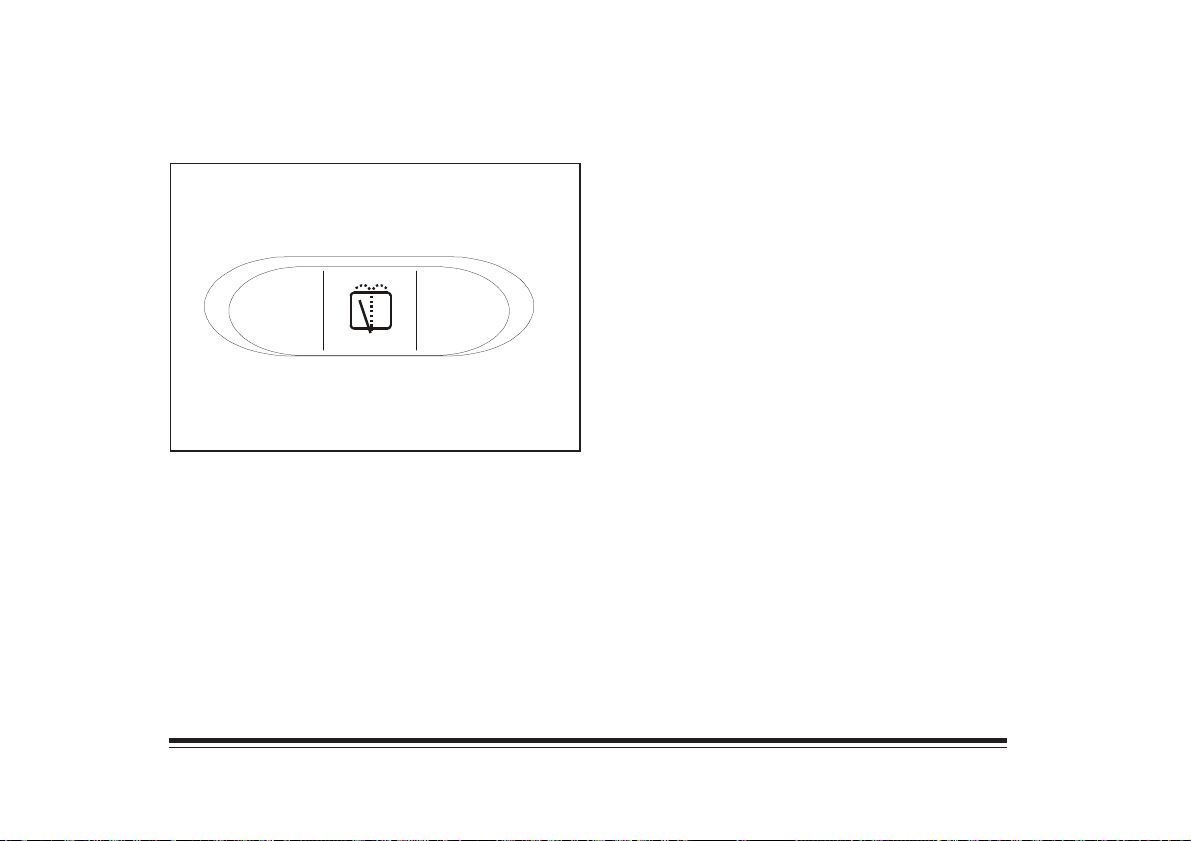
Rear Window Washer/Wiper (Option)
WASH
To turn the rear wiper on, press ON. The wipper will
operate in five seconds intervals.
To spray washer fluid on the rear window, press and
hold ON.
To turn the rear wiper off, press OFF.
ON
OFF
REAR WIPER
Some vehicles are equipped with a rear wiper for the
rear window.
The rear washer uses the same fluid bottle as the
windshield washer.
1-21
Page 30
Mirrors
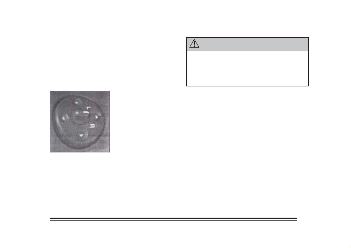
Outside Mirrors
Adjust the outside mirrors so that you can just
see the side of your vehicle when you are sitting in a
comfortable driving position. You should fold the
mirrors inward to prevent damage when going through a
car wash or narrow streets
The outside mirror control
is located on the driver’s
door armrest. Turn the
control to L or R to choose
the mirror, then press the
arrows on the outside switch
ring to adjust the mirror.
CAUTION:
The outside mirrors make object appear to be farther
away than they really are. Check your
inside mirror or glance over your shoulder before
changing lanes.
1-22
Page 31
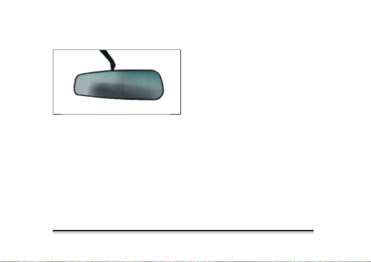
Inside Day/Night Rearview Mirror
The mirror has two pivots so that you can adjust it
up and down or side to side.
Pull the tab at the base of the mirror for night
driving and press it for day driving.
Sun Visors
To block out glare, you can swing down the top and
bottom visors. You can also swing the botton visor from
side to side. Your visors may have an extension that can
be pulled out for additional glare protection and a strap
for holding small items, such as maps.
Visor Vanity Mirror
Pull the sun visor down and lift the cover, if you have
one, to expose the vanity mirror.
1-23
Page 32
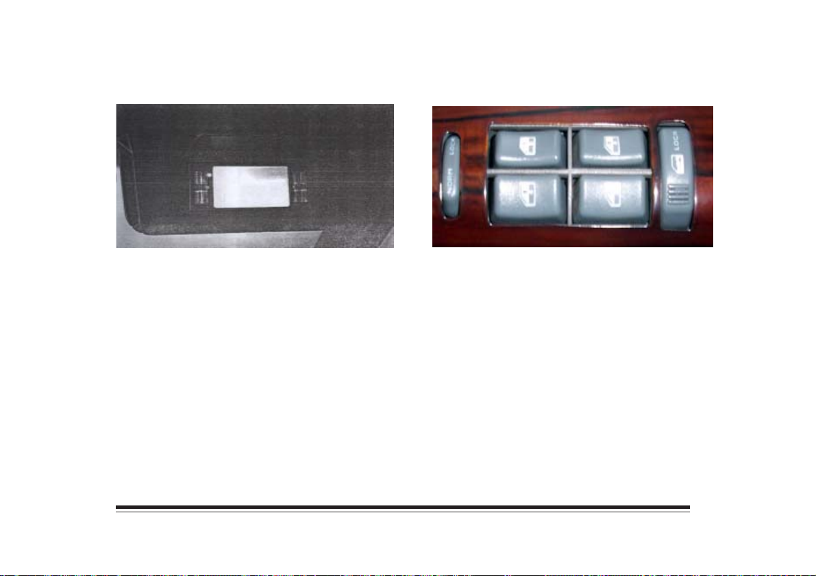
Illuminated Visor Vanity Mirror
Power Windows
Pull the passenger’s side sun visor down and lift the
mirror cover to turn on the lamps. You may also have
an illuminated mirror on the driver’s side.
Power window switches on the driver’s door control
each of the windows when the ignition is in the RUN
position. Press the side of the switch with the up arrow
to close a window. Press the side of the switch with the
down arrow to open a window.
Each passenger door has a control switch for its own
window.
1-24
Page 33
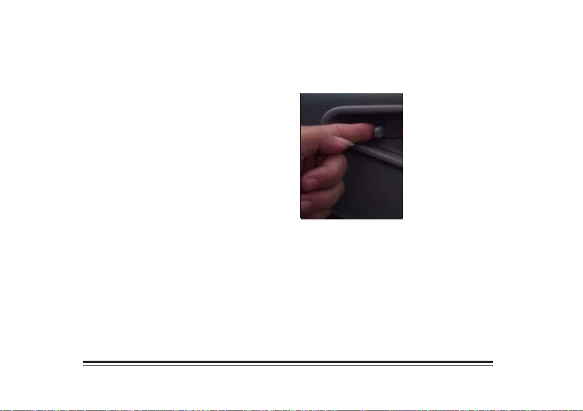
Lockout Switch
The lockout feature prevents passengers from
operating power windows. Press LOCK to activate
this feature. Press NORM and the windows return to
normal operation.
Doors
Door Locks
You can use the manual
door lock to lock and unlock
each door individually from
the inside.
Use your key to lock or unlock the front doors from the
outside.
For safety reason, only one side door can open with
key and if you want to open all door you must press
LOCK or UNLOCK to open and lock all door.
1-25
Page 34
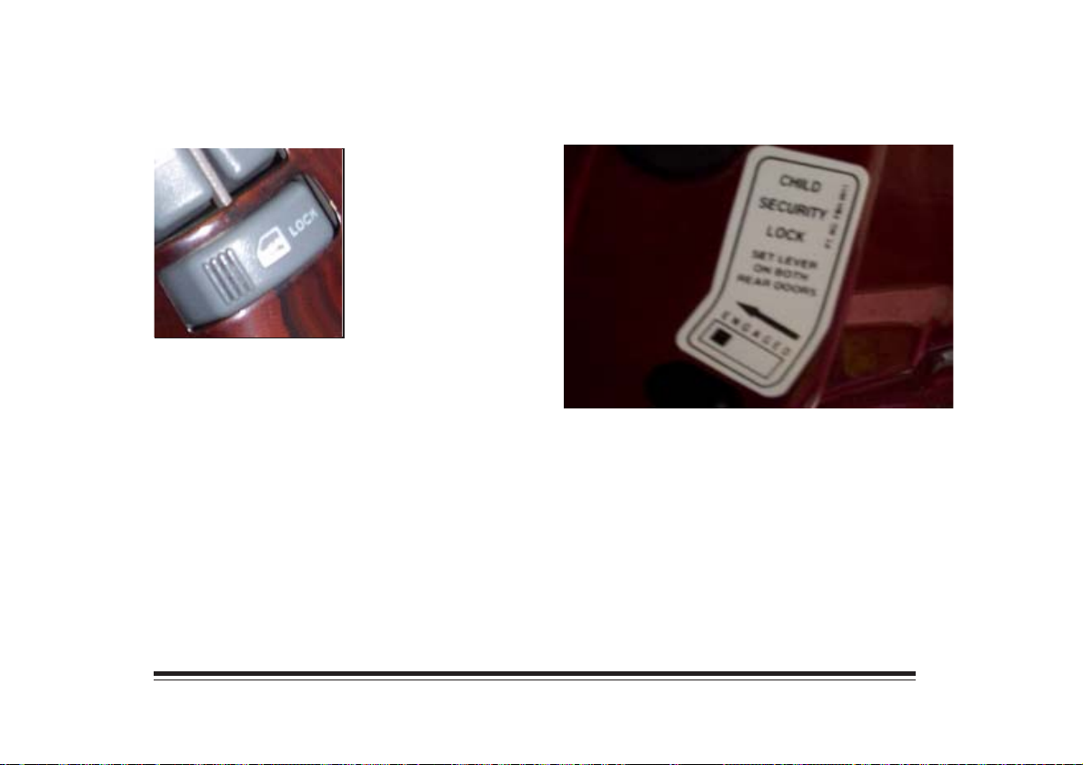
Power Door Locks
The switch is located on
the armrest.
Press LOCK to locak all the doors at once. To unlock the
doors, press the raised area next to the key symbol.
Rear Door Security Locks
The lever on each rear door works only that door’s lock.
The rear doors are equipped with locks that help prevent
pasengers, especially children, from opening the rear
doors from the inside.
To use this feature, open a rear door and move the
switch to ENGAGED. Open the door from the outside
and move the switch away from ENGAGED to
disengage this feature.
1-26
Page 35
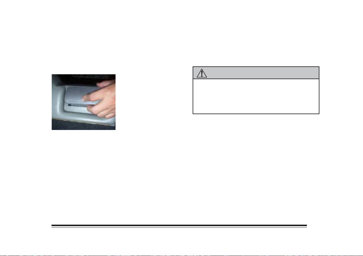
Rear Cargo Area
Endgate Release
Insert the key in the lock button and turn counterclock
wise. All the door will unlock.
Press the button to open
the glass and reach inside
the endgate to lift the
handle and open the
endgate. The endgate
can be opened without
a key if the passenger’s
door is unlocked.
To lock a power lock system from outside, insert the
key in the lock button and turn clockwise. All doors
will lock.
CAUTION:
It can be very dangerous to drive with the
endgate open. Carbon monoxide (CO) gas can
come into your vehicle. You can not see or smell
carbon monoxide. It can cause unconsciousness
and even death.
1-27
Page 36
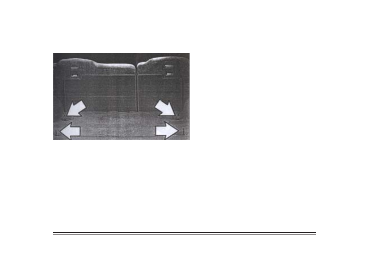
Cargo Tie Downs
Your vehicle is equipped with two cargo barriers and
four tie down loops fro securing objects in the rear area.
Jack and Spare Tire
The jack and spare tire are located in the rear area of
your vehicle. See Section 5 for more information on
spare tire removal and changing a flat tire.
Overhead Console (Option)
The front overhead console has reading lamps, garage
door opener provisions and storage compartments.
Each reading lamp has an on/off switch next to it.
There are two storage compartments. The center
compartment is for eyeglasses and the rear one is
for small items. Press the release button to open
either compartment.
1-28
Page 37
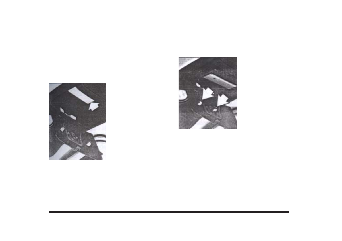
Installing a Garage Door Opener
If you have a garage door opener, the front overhead
compartment can be used to conveniently store the
opener.
To install the garage door opener, first open the
compartment door by pressing the latch forward.
Peel the protective backing
from the hook and loop
patch.
Press it firmly to the back of your garage door opener,
as close to the center of the opener as possible.
Center the garage door opener activation button over
the console door button and press the opener firmly
into place.
The pegs inside the
compartment door are used
to make sure the button on
the compartment door will
contact the control button
on the garage door opener.
Add one peg at a time until the garage door opener
operates with the compartment door closed when you
press the button.
1-29
Page 38
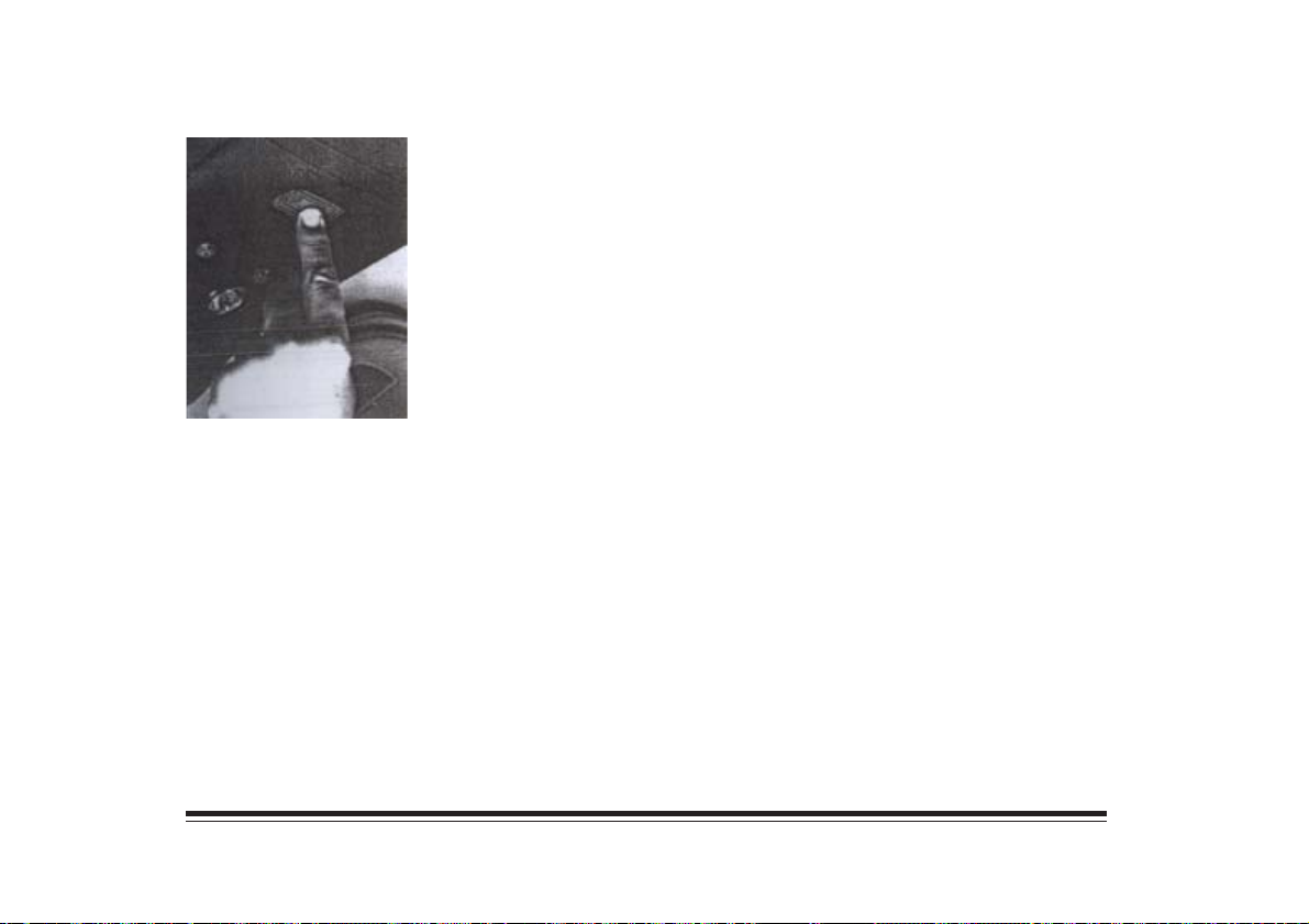
Now with the compartment
door closed, press the
button again to make sure
the garage door opener
operates properly.
With the garage door opener positioned properly and the
right number of pegs in place, you should only have to
press the button slightly to operate the opener. Adjust the
position of the garage door opener and add or remove
pegs, as needed, until the opener opertaes properly.
Turn the display on or off by pressing the ON/OFF
switch. Display the tempreature in either degrees
Fahrenheit (English) or Celcius (metric) by pressing the
US/MET switch.
Before you turn on the ignition and move the vehicle,
the temperature indicated will be the last outside
temperature recorded with the ignition on.
The compass is self-calibrating, so it does not need to
be manually set. However, when your vehicle is new,
the compass may function erratically. If it does, CAL
(Calibration) will appear on the display. To correct the
problem, drive in a complete 360° circle three times.
Storage
The front doors provide space fo storage.
There are also storage areas in the overhead console.
Temperature and Compass Display
The outside air temperature and the compass are
displayed at the front of the overhead console. The
control switches are located to the left of the display.
The glove box include cupholders.
You may have a console compartment which includes
cupholders, coinholders and a storage area for cassettes.
1-30
Page 39

NOTES
1-31
Page 40

NOTES
1-32
Page 41
Section 2 Seats and Safety Belts
Read this section to learn how to use the seat controls
and the safety belts. To help protect yourself and your
passengers, you must know how to use the safety belts
in your vehicle.
Seat Controls
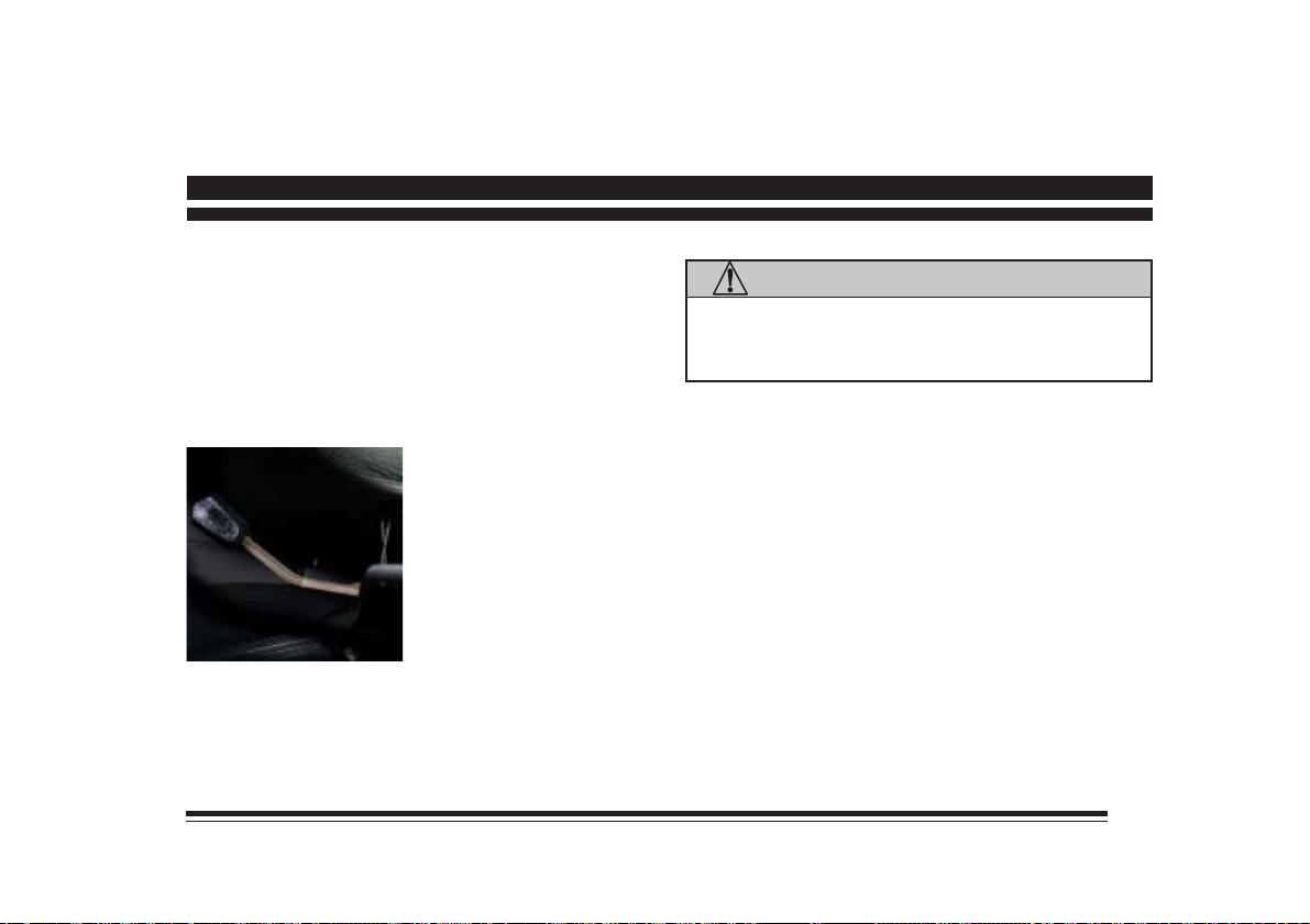
Manual Seat Lever
Move the lever to unlatch
the front seat. Slide the
seat to where you want it.
Release the lever and
make sure the seat is
locked into place.
CAUTION:
Do not adjust the driver’s seat when the vehicle
is moving. The seat could jerk and cause a loss
of control.
2-1
Page 42
Reclining Front Seatback
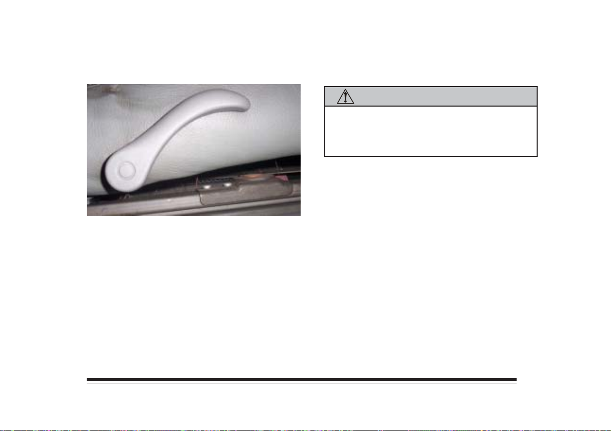
To recline the seatback, lift the lever and tilt the
seatback forward or backward, as desired. Release the
lever to lock the seatback in place.
CAUTION:
Sitting in a reclined position when your vehicle is
in motion can be dangerous. Even if you buckle
up, your safety belts can’t do their job when the
seatback is excessively reclined.
Head Restraints
For your convenience, the front head restraints are
removable for maintenance purposes.
2-2
Page 43
Folding Rear Seatback
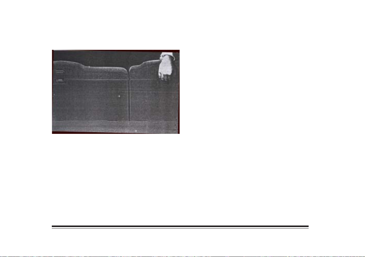
Your vehicle has a folding rear seta which let you fold
the seatbacks down for more cargo space. The rear seat
release handles are in the upper center of the rear of
the seatbacks.
To fold the seatback, push back on the seatback as you
pull up on the handles.
To raise the seatbacks, just lift up the seatbacks and push
until they lock in the upright position.
Push and pull on the seatbacks to check that the latches
have locked in the upright position. If they haven’t, have
them fixed immediately.
2-3
Page 44
Safety Belts
Lap-Shoulder Belt
CAUTION:
Do not let anyone ride where they cannot wear a
safety belt properly. If you are in a crash and you
are not wearing a safety belt, you can be seriously
injured or killed. In the same crash, you might
not be injured if you are buckled up. Always
fasten your safety belt, and check that your
passenger’s belts are fastened properly too.
The lap-shoulder belt should be worn properly, as
described. To fasten the belt:
1. Adjust the seat and sit up straight.
2. Pick up the latch belt.
3. Pull the belt across you. Do not let it get twisted.
2-4
Page 45
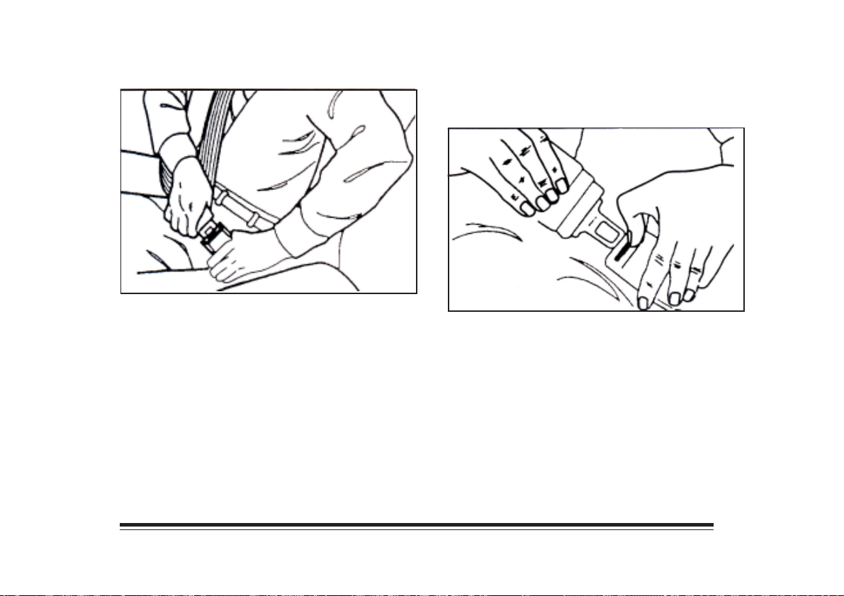
4. Push the latch plate into the buckle until it clicks. If
the rear seat belt stops before it reaches the buckle,
tilt the latch plate and keep pulling until you can
buckle it. Make sure the release button on the buckle
faces upward or outward.
5. Pull on the shoulder part to adjust the lap fit. To
unlatch the belt, press the button on the buckle.
2-5
Page 46
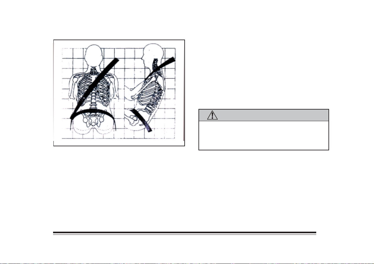
The lap part of the belt should be worn low and snug on
the hips, just touching the thighs. In a crash, this applies
force to the strong pelvic bones. And you’d be less
likely to slide under the lap belt. If you slid under it, the
belt would apply force at your abdomen. This could
cause serious or even fatal injuries. The shoulder belt
should go over the shoulder and across the chest.
These parts of the body are best able to take belt
restraining forces.
CAUTION:
Wear your belt fitted closely against the body.
Do not wear your shoulder belt under your
arm. Make sure the belt is not twisted across
your body.
2-6
Page 47
Shoulder Belt Height Adjuster
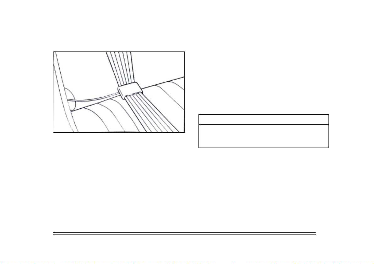
Your vehicle may be equipped with the rear shoulder belt
guides which provide comfort and support for small
adults and children. These guides work by pulling the
regular belt away from the neck and head.
To install the comfort guide:
1 Pull the elastic cord out from between the seat and
inside body of the vehicle and remove the guide
from the chip.
2 Place the guide over the belt, inserting the belt edges
into the slots of the guide.
3 Be sure the belt is not twisted and that the elastic
cord is under the belt and the guide is on top.
NOTICE:
Before you close the door, make sure the safety
belt is out of the way, Otherwise, the belt and/or
the vehicle body could be damaged.
2-7
Page 48
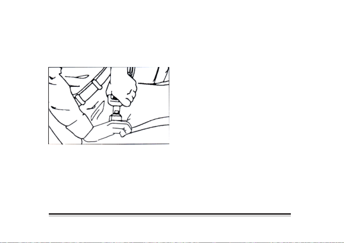
Lap Belt
The center passenger position has a lap safety belt with no
retractor. Follow these instructions to wear it properly:
1. Pull the latch plate as you tilt and extend the belt.
2. Push the latch plate into the buckle until it clicks.
Make sure the release button on the buckle faces
upward or outward.
3. To tighten the belt, hold the buckle and pull on
the slack.
To unlatch the belt, press the button on the buckle.
Replacing Safety Belts
If you have been in a collision where the belts may have
been stretched, or if the safety belt is cut or damaged,
the belt needs to be replaced. Repairs may be necessary
even if the safety belt was not used at the time of
the collision. Have the restraint system inspected
after a collision.
2-8
Page 49
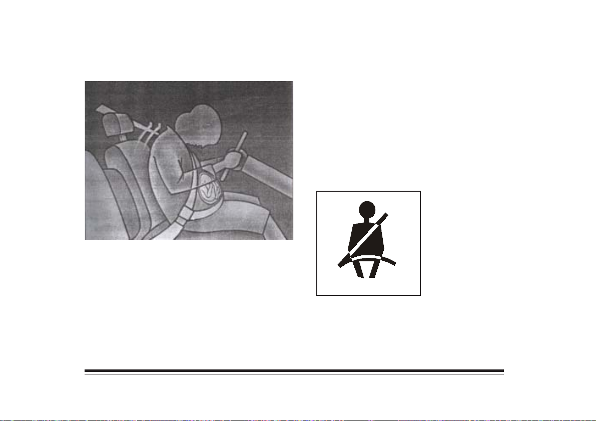
Safety Belt Use During Pregnancy
Safety belts work for everyone, including pregnant
women. Like all occupants, they are more likely to be
seriously injured if they don;t wear safety belts.
A pregnant woman should wear a lap-shoulder belt,
and the lap portion should be worn as low as possible,
below the rounding, throughout the pregnancy.
The best way to protect the fetus is to protect the
mother. When a safety belt is worn properly, it’s more
likely that the fetus won’t be hurt in a crash. For
pregnant women, as for anyone, the key to making
safety belts effective is wearing them properly.
Safety Belt Reminder Light
This light will come on
briefly when the ignition
key is turned to RUN or
START. A tone may also
sound.
2-9
Page 50
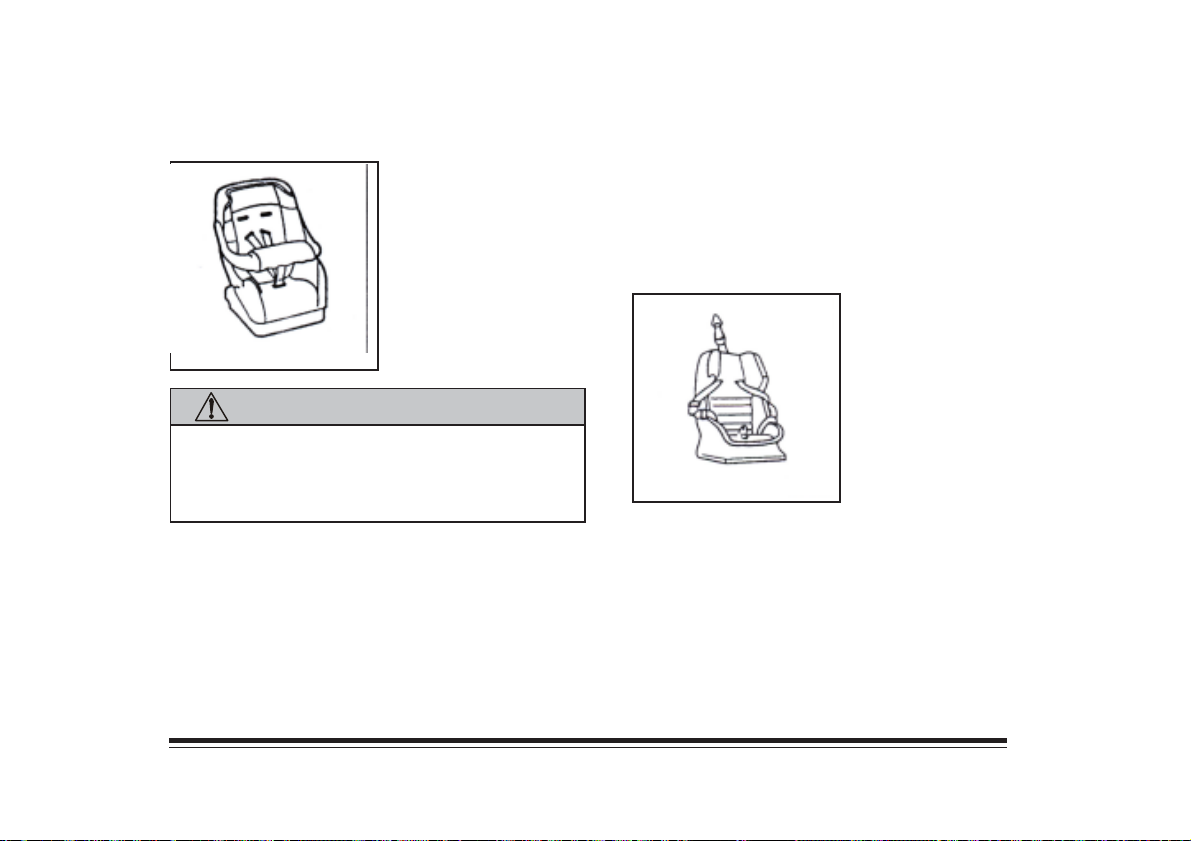
Child Restraints
CAUTION:
Children who are small enough should always
be restrained in an infant or child restraint.
Never hold a baby in your arms while riding in
a vehicle.
Children restrains use the safety belt system in your
vehicle, but the child also has to be secured within the
restraint to help reduce the chance of personal injury.
Follow the instructions that come with the infant or
child restraint.
Top Strap
A child restraint may have
a top strap. If it does, it
should be anchored. Ask
your dealer to install an
anchor bracket.
2-10
Page 51

NOTES
2-11
Page 52

NOTES
2-12
Page 53
Section 3 Starting and Operating Instructions
This section explains how to start and operate your
vehicle.
New Vehicle “Break-In”
NOTICE:
Your vehicle doesn’t need an elaborate
“break-in.” But it will perform better in the long
run if you follow these guidelines:
• Keep tour speed at 90 km/h or less for the
first 800 km.
NOTICE: (Continued)
NOTICE: (Continued)
• Don’t drive at a constant speed – fast or
slow – for the first 800 km. Don’t make
full-throttle starts.
• Avoid making hard stops for the first
320 km or so. Hard stops with the new brake
linings can mean premature wear. Follow
this brake-in guideline every time you get
new brake linings.
3-1
Page 54
Keys
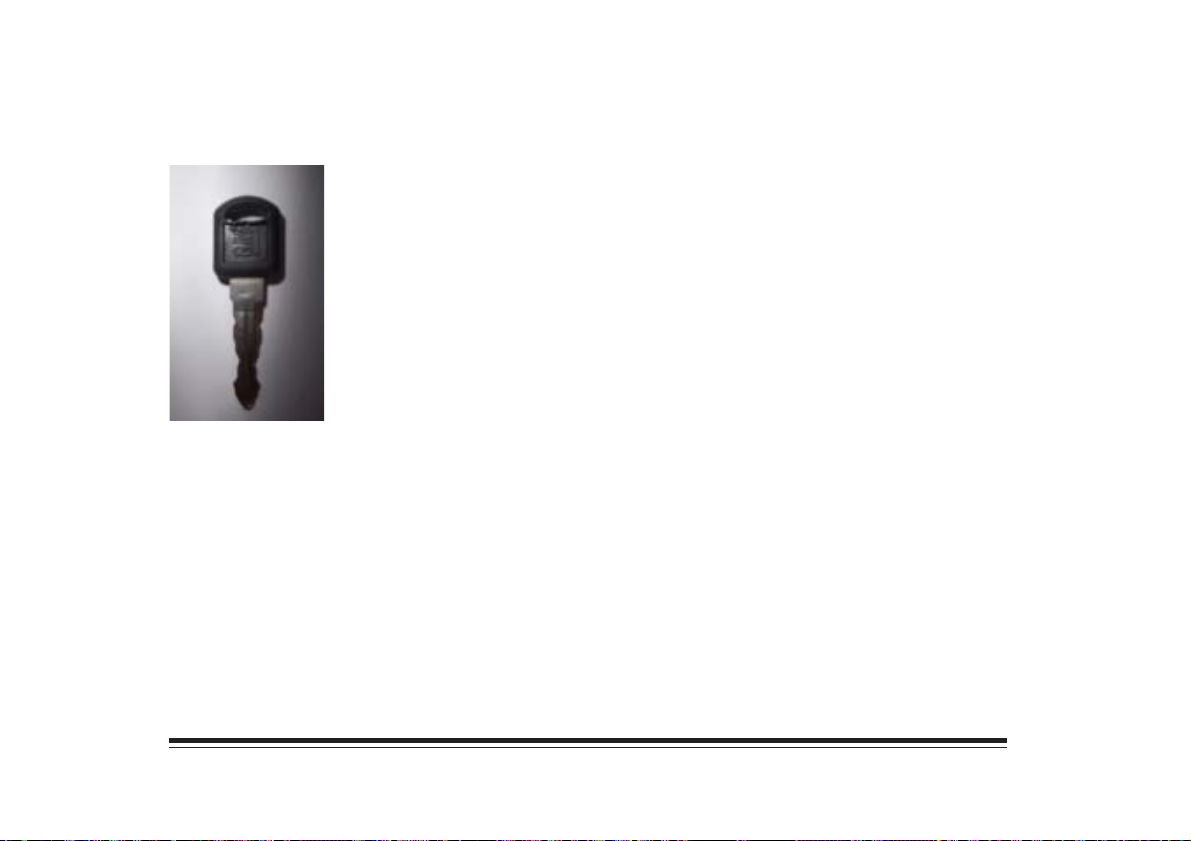
This vehicle has one
double-sided key which is
used for the ignition and
all the locks.
The key has a bar code tag which is given to the first
owner at delivery. The bar code tells your dealer or a
qualified locksmith how to make extra keys. Keep this
tag in a safe place. If you lose your keys, you’ll be able
to have new ones made easily using this tag.
3-2
Page 55
Ignition Switch
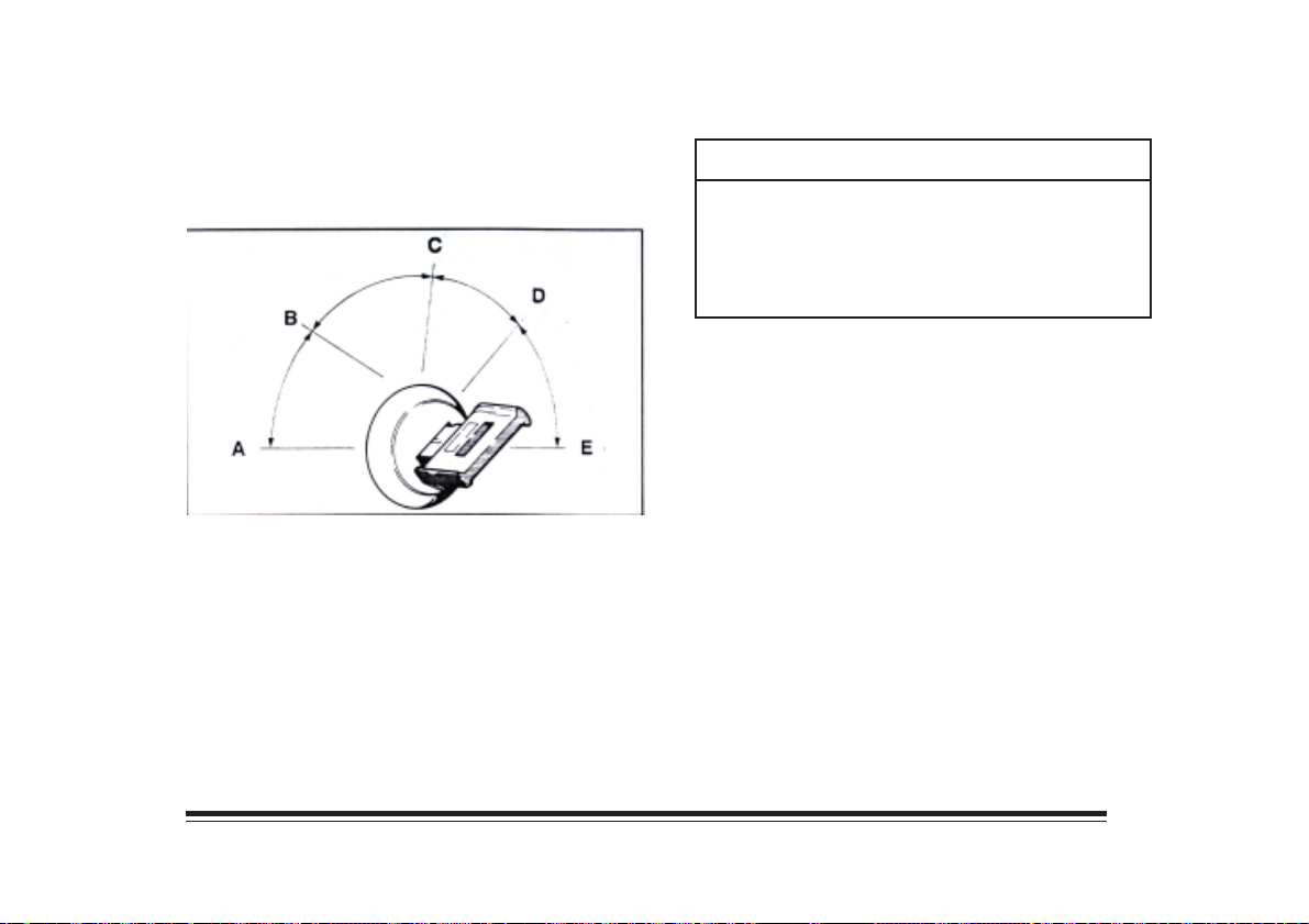
Use the key to turn the ignition switch to five different
positions.
ACCESORY (A): ACCESSORY lets you use things
like the radion and the windshield wipers when the
engine is off. Push in the key and turn it toward you.
Your steering wheel will remain locked, just as it was
beore you inserted the key.
NOTICE:
Don’t operate accessories in the ACCESSORY
position for long periods of time. Prolonged
operation of accessories in the ACCESSORY
position could drain your battery and prevent you
from starting your vehicle.
LOCK (B): This position locks your ignition and
steering wheel. It’s a theft-deterrent feature. You will
only be able to remove your key when the ignition is
turned to LOCK.
OFF (C): This position unlocks the steering wheel
and ignition. Use this position if your vehicle must be
pushed or towed, but never try to push-start the engine.
A warning tone will sound if you open the driver’s door
when the igniton is off and the key is in the ignition.
RUN (D): This is the position for driving.
START (E): This start your engine. When the engine
starts, release the key. The ignition switch will return
to RUN.
3-3
Page 56
NOTICE:
If your key seem stuck in LOCK and you can;t
turn it, be sure it is all the way in. If it is, then
turn the steering wheel left and right while you
turn the key hard. But turn the key only with
your hand. Using a tool to force it could break
the key or the ignition switch. If none of this
works, then your vehicle needs service.
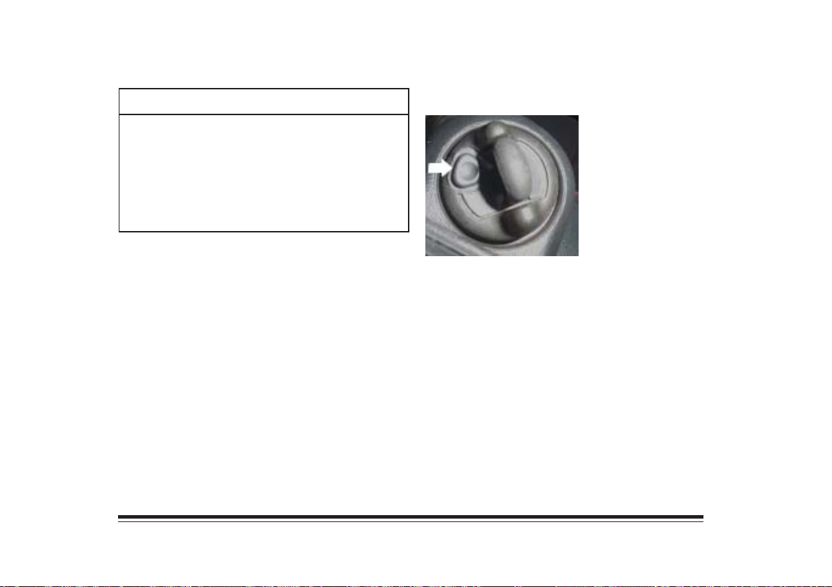
Key Release Button
The key cannot be removed
from the ignition unless the
key release button is used.
Press the button as you turn
the key toward you.
3-4
Page 57
Starting Instructions
The gear selector should be in NEUTRAL (N).
2. If it doesn’t start right away, hold your key in
START. If it doesn’t start in 10 seconds, push the
accelerator pedal all the way down for five seconds,
or until it starts.
CAUTION:
It can be dangerous to start your vehicle in any
other gear besides NEUTRAL (N). You or others
could be hurt. Be sure the shift lever is in
NEUTRAL (N) before starting your engine.
1. Without pushing the accelerator pedal, turn your
ignition key to START. When the engine starts, let
go of the key. The idle speed will go down as your
engine gets warm.
NOTICE:
Holding your key in START for longer than
15 seconds at a time will cause your battery to
be drained much sooner. And the excessive heat
can damage your starter motor.
3. If your engine still won’t start, wait 15 seconds to
let the starter motor cool down and do it all again.
When the engine starts, let go of the key and the
accelerator pedal.
NOTICE:
Your engine is designed to work with the
electronics in your vehicle. If you add the electrical
parts or accesories, you could change the way
engine operates. Before adding electrical
equipment, check with your dealer. If you don’t
your engine might not perform properly.
3-5
Page 58
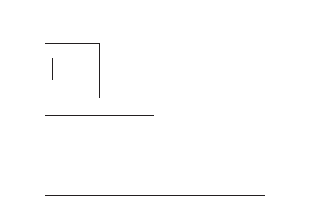
Manual Transmission
This is your vehicle’s
135
2
4R
shift pattern.
NOTICE:
Shift to REVERSED (R) only after your vehicle is
stopped. Shifting to REVERSE (R) while your
vehicle is moving could damage your transmission.
Vehicle Parking
Place your transmission in REVERSE (R) and firmly
apply the parking brake.
Control of A Vehicle
There are three systems that control the vehicle: the
steering, the brakes and the accelerator. To keep the
vehicle under control, do not push any of these systems
beyond their limit.
Steering
Power Steering
If you lose power steering assist because the engine
stops or the system is malfuntion ning, you can steer
but it will take much more effort.
3-6
Page 59
Brakes
If the engine stops as you are driving, brake normally but
don’t pump your brakes. If the engine stops, you will
have some power brake assist left, but it’s used up as you
brake.
Disc Brake Wear Indicators
Your vehicle has fron disc brakes and rear drum brakes.
Disc brake pads have built-in wear indicators that make a
hight-pitched warning sound when the brake pads are
worn and new ones are needed.
Rear Brakes
Your rear brakes don’t have the wear indicators. If you
ever hear a rear brake rubbing noise, have the rear brake
linings inspected. The rear brake drums should be
removed and inspected each time the tires are removed
for rotation or changing.
Brake Adjustment
Every time you make a moderate brake stop, your disc
brake adjust themselves for wear. If you almost never
make a moderate or heavier stop, then your disc brakes
might not adjust correctly. If you drive that way,
then – very carefully – make a few moderate
brake stops about every 1600 km, so your brakes
will adjust properly.
If the brake pedal goes down farther than normal, it may
be due to a lack of adjustment of the rear drum brakes.
To adjust them, drive backward and forward a few
times, applying the brakes firmly when going in
each direction.
3-7
Page 60
Brake Pedal Travel
See your dealer if the brake pedal does not return to
normal height, or if there is a rapid increase in pedal
travel. This could be a sign of brake trouble.
Anti-Lock Brake System
The anti-lock brake system helps you maintain
directional stability on wet or slippery road surfaces.
It automatically controls the brake operation
when braking.
This occur only during a brake application which
would have caused one or both the rear wheels to lock. You
don’t have to pump the brakes. Just hold the brake pedals
down. You may feel it pulsate, but this is normal.
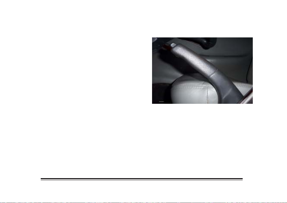
Parking Brake
The parking brake is on the floor, between the front
seats. Pull the lever to apply the parking brake.
Press the button and lower the lever to release the
parking brake.
3-8
Page 61
Vehicle Loading
Maximum Front and Rear Axle Weights
The GVWR (Gross Vehicle Weight Rating) is the
maximum permissible loaded weight of the vehicle,
taking into account the capability of the engine,
transmission, frame, springs, brakes, axles and tires.
The weight of the cargo load must be properly
distributed over both the front and rear axles. The
Certification label shows the maximum weight that the
front axle can carry (fron GAWR) and the maximum
weight that the rear axle can carry (rear GAWR).
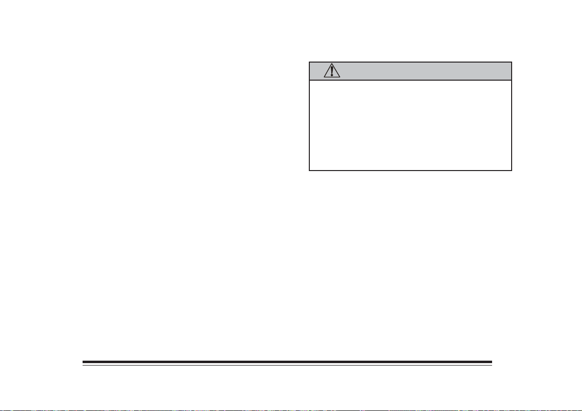
CAUTION:
The components of your vehicle are designed to
provide satisfactory service if the vehicle is not
loaded in excess of front and rear Gross Axle
Weight Ratings (GAWR’s). Overloading can
result in loss of the vehicle control and personal
injury. It can also shorten the service life of
your vehicle.
3-9
Page 62
Certification Label
Your Certification label shows the GVWR and both
front and rear GAWR’s. The label is located on the edge
of the driver’s door.
Suspension
The suspension system in your vehicle is designed to
keep the vehicle level and to provide a smooth and
controlled ride.
3-10
Page 63
Section 4 Service and Maintenance
This section contains information about fuel
requirements, maintenance items and specifications.
Leaded Fuel
You should use 88RON leaded gasoline. The use of
other gasolines may cause engine knock. Continued
use can cause engine damage.
If you detect a heavy engine knock even when using
88RON leaded gasoline, have the engine checked.
Short periods of engine knock during hill climbing and
acceleration are acceptable.
CAUTION:
Gasoline vapor is highly flammable. Keep
sparks, flames and smoking materials away
from gasoline.
Filling the Tank
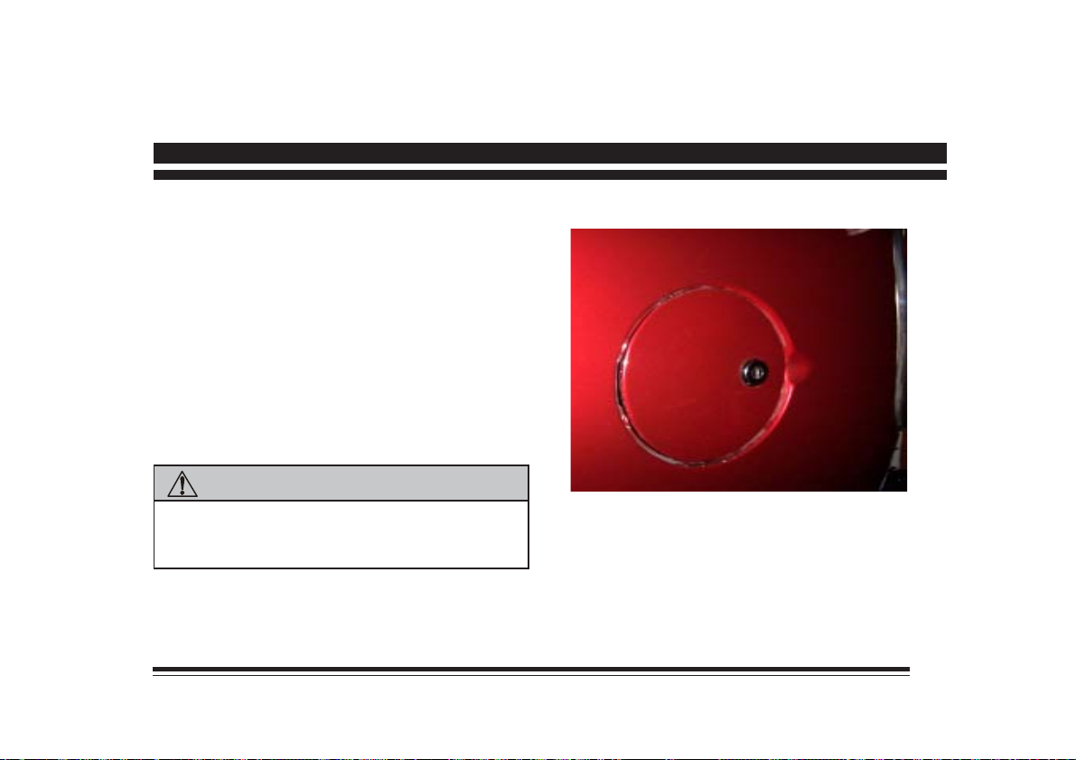
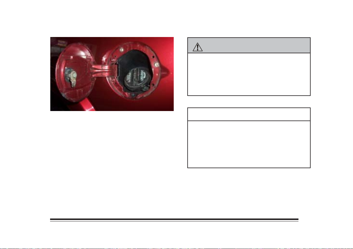
The cap is behind a hinged door on the left side of your
vehicle. Use the ignition key to unlock the door.
4-1
Page 64
CAUTION:
If you open the cap rapidly while pressure inside
the tank is high, gasoline may spray out from the
tank. Before you fully open the cap, turn it
slightly to release the pressure from inside the
tank to avoid possible injury.
Remove the fuel filler cap by slowly turning it
counterclockwise. Replace it by turning it clockwise.
When you put the cap back on, continue to turn it
clockwise until you hear a clicking noise.
NOTICE:
If you have to get a new cap, be sure to get the
right one. Otherwise the cap might not have
the proper venting. This could lead to serious
fuel system and other damage. Your dealer
knows the correct cap for your vehicle.
4-2
Page 65
Hood Release
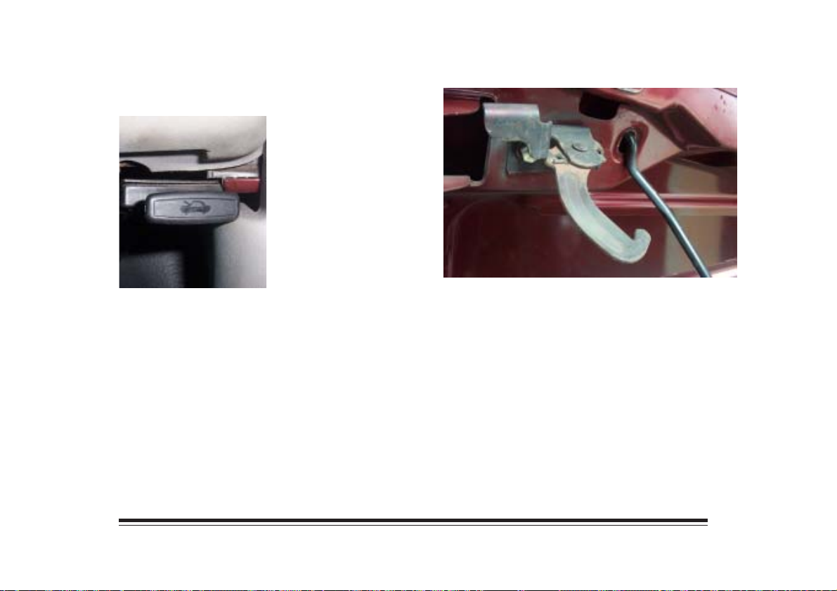
To open the hood, first pull
the handle inside the
vehicle, located below the
lower right side of the
instrument panel.
Then go to the front of the vehicle and release the
secondary hood release. Lift the hood.
Hold the hood open with the hood prop.
4-3
Page 66
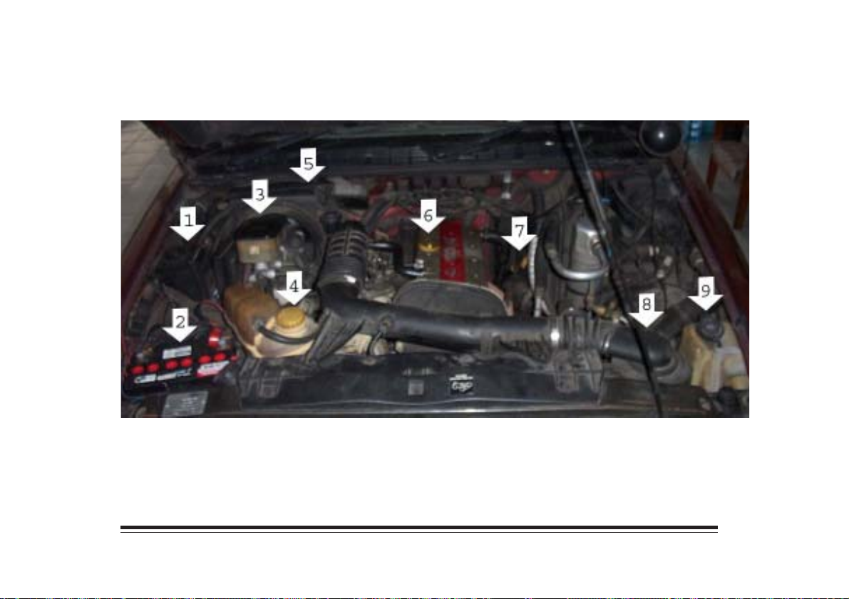
When you open the hood of the dual cam engine, you’ll see:
1. Power Steering Reservoir
2. Battery
3. Brake Master Cylinder
4. Engine Coolant Reservoir
5. Hydraulic Clutch Reservoir
6. Engine Oil Fill Cap
7. Engine Oil Dipstick
8. Air Cleaner Filter
9. Windshield Washer Reservoir
4-4
Page 67
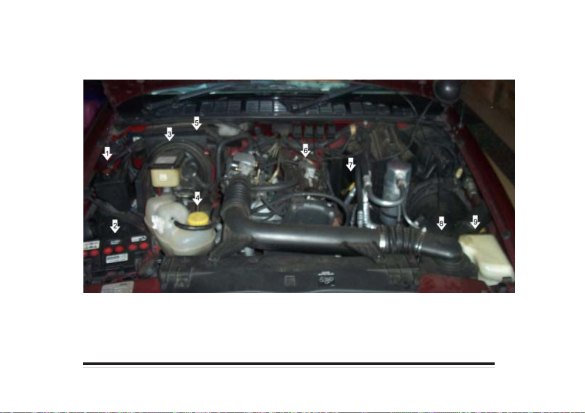
When you open the hood of the single cam engine, you’ll see:
1. Power Steering Reservoir
2. Battery
3. Brake Master Cylinder
4. Engine Coolant Reservoir
5. Hydraulic Clutch Reservoir
6. Engine Oil Fill Cap
7. Engine Oil Dipstick
8. Air Cleaner Filter
9. Windshield Washer Reservoir
4-5
Page 68
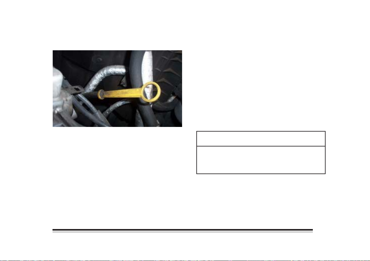
Engine Oil
few minutes to drain back into the oil pan. If you
don’t, the oil dipstick might not show the actual level.
Pull out the dipstick and clean it with a paper towel or
cloth, then push it back in all the way. Remove it
again, keeping the tip down, and check the level.
If the oil is at or below the MIN, then you’ll need to
add some oil. But you must use the right kind. This
part explains what kind of oil to use. For crankcase
capacity, see “Capacities and Specifications” in the
Index.
It is the owner’s responsibility to check the engine oil
level regularly. Turn off the engine and give the oil a
NOTICE:
Don’t add too much oil. If your engine has so much
oil that the oil level gets above MAX, your engine
could be damaged.
4-6
Page 69
Just fill it enough to put the level somewher in the
proper operating range. Push the dipstick all the way
back in when you’re through.
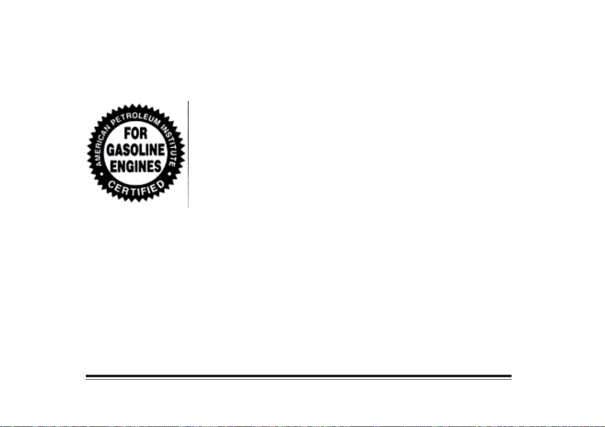
Oils recommended for
your vehicle can be
identified by looking for
the “Startbust” symbol.
This symbol indicates that the oil has been certified
by the American Petroleum Institute (API). Use
engine oil type with code API classification SG or
higher.
You should use 10W-30, 10W-40 or 10W-50 oil
for your vehicle. Do not use other viscosity oils,
such as 80W-90.
These number on an oil container show its viscosity, or
thickness.
Don’t add anything to your oil. Your dealer is
ready to advise you if you think something should
be added.
4-7
Page 70
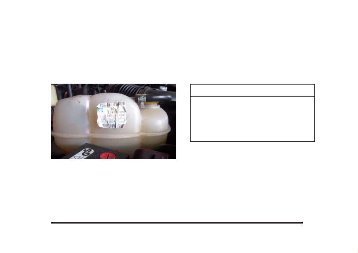
Engine Coolant
The cooling system in your vehicle is filled with the
new long life engine coolant.
If you have a problem with engine overheating, see
“Engine Overheating” in the Index.
You should check the coolant level regularly. When
your engine is cold, the coolant level should be at
COLD or a little higher. If you need more coolant, add
a 50/50 mix of clean water and extended life coolant at
the coolant recovery tank. Be careful not to spill it.
NOTICE:
When adding coolant, it is important that you use
long life coolant. If silicated coolant is added to
the system, premature engine, heater core or
radiator corrosion may result and the coolant will
require change sooner.
4-8
Page 71
CAUTION:
NOTICE:
Adding only plain water to your cooling system
can be dangerous. Plain water, or some other
liquid like alcohol, can boil before the proper
coolant mix will. With plain water or the wrong
mix, your engine could get too hot but you
wouldn’t get the overheat warning. Your engine
could catch fire and you or others could be
burned. Use a 50/50 mix of clean water and
extended life coolant.
If you use an improper coolant mix, your engine
could overheat and be badly damaged. Too much
water in the mix can freeze and crack the engine,
radiator, heater core and other parts.
CAUTION:
You can be burned if you spill collant on hot
engine parts. Coolant contains ethylene glycol,
and it will burn if the engine parts are hot
enough. Don’t spill coolant on a hot engine.
4-9
Page 72
Manual Transmission Fluid
A good time to have it checked is when the engine oil is
changed. However, the fluid in your manual transmission
doesn’t require changing.
Check the fluid level only when your engine is off, the
vehicle is parked on a level place and the transmission
is cool enough for you to rest your fingers on the
transmission case.
Then, follow these steps:
1. Remove the filler plug.
2. Check that the lubricant level is up to the bottom of
the filter plug hole.
3. If the fluid level is good, install the plug and be sure
it is fully seated. If the fluid level is low, add more
fluid as described in the next steps.
To add fluid:
1. Remove the filler plug.
2. Add fluid at the filler plug hole. Add only enough
fluid to bring the fluid level up to the bottom of
the filler plug hole.
3. Install the filter plug. Be sure the plug is fully
seated.
Hydraulic Clutch Fluid
The hydraulic clutch in your vehicle is self adjusting.
A slight amount of play (2/3 cm to 1 ½ cm) in the pedal
is normal.
The proper fluid should be added if the level does not
reach the bottom of the diaphragm when it’s in place in
the reservoir. See the instruction on the reservoir cap.
Power Steering Fluid
It is not necessary to regularly check power steering
fluid unless you suspect there is a leak in the system or
you hear an unusual noise. A fluid loss in this system
could indicate a problem. Have the system inspected
and repaired.
4-10
Page 73
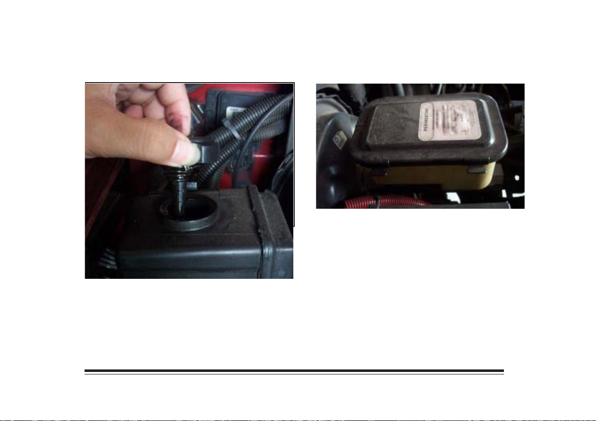
How To Check Power Steering Fluid
When the engine compartment is cool, unscrew the cap
and wipe the dipstick with a clean rag. The level
should be at the C mark. If necessary, add only enough
fluid to bring the level up to the proper range. Replace
the cap and completely tighten it. Then remove the cap
again and look at the fluid level on the dipstick.
Brake Master Cylinder Fluid
There are only two reasons why the brake fluid level in
the reservoir might go down. The first is that the brake
fluid goes down to an acceptable level during normal
brake lining wear. When new linings are put in, the
fluid level goes back up. The other reason is that fluid
is leaking out of the brake system. If it is, you should
have your brake system fixed, since a leak means that
sooner or later your brakes won’t work well, or won’t
work at all.
4-11
Page 74
It isn’t a good idea to “top off” your brake fluid. Adding
brake fluid won’t correct a leak. If you add fluid when
your linings are worn, then you’ll have too much fluid
when you get new brake linings. You should add (or
remove) brake fluid, as necessary, only when work is done
on the brake hydraulic system.
CAUTION:
If you have too much brake fluid, it can spill on the
engine. The fluid will burn if the engine is hot
enough. You or others could be burned, and your
vehicle could be damaged. Add brake fluid only
when work is done on the brake hydraulic system.
You can check the brake fluid without yaking off the cap.
Just look at the windows on the brake fluid reservoir.
The fluid levels should be above MIN. If they aren’t,
have your brake system checked to see if there is a leak.
Air Conditioning Refrigerants
Not all air conditioning refrigerants are the same.
If the air conditioning system in your vehicle needs
refrigerant, be sure the proper refrigerant is used. Use
only R-134a refrigerant.
4-12
Page 75
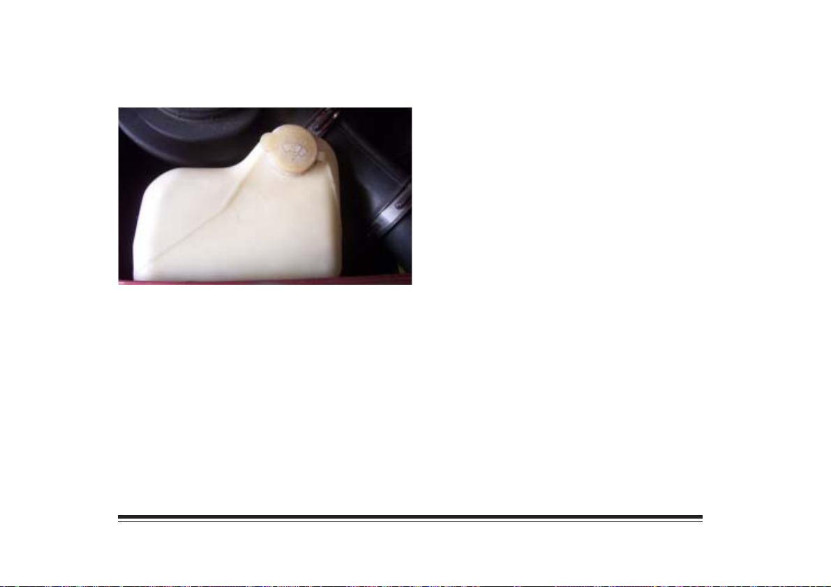
Windshield Washer Fluid
Use Prestone Windshield Washer Solvent, or an
equivalent, rather than water for better cleaning.
Battery
You should check the electrolyte level regularly.
Remove the vent plug. If the level is low, add
drinking-quality water that is colorless and odorless.
Add water until the level reaches the split vent located
in the bottom of the vent well. Do not overfill.
Overfilling will result in poor performance, short life
and excessive corrosion.
Check the outside of the battery periodically for
damage. Remove acid film and dirt with diluted
ammonia and flush with water.
4-13
Page 76
Vehicle Storage
If you’re not going to drive your vehicle for 25 days or
more, take off the black, negative (-) cable from the
battery. This will help keep your battery from running
down.
Contact your dealer to learn how to prepare your
vehicle for longer storage periods.
Air Cleaner Filter
Follow these instructions to change the air filter.
1. Remove the clamp from the fender to air intake.
In addtion, remove the clamp from the air duct to
the engine.
2. Unsnap the air cleaner clips that hold the two
assembly halves together.
3. Unsnap the band that holds the air cleaner
assembly to the vehicle.
4. Lift off the top half of the air cleaner.
5. Remove the filter element.
6. Clean any dirt and debris from the bottom of the
housing.
7. Reverse Steps 1 through 5 to install a new air
filter.
4-14
Page 77
Tires
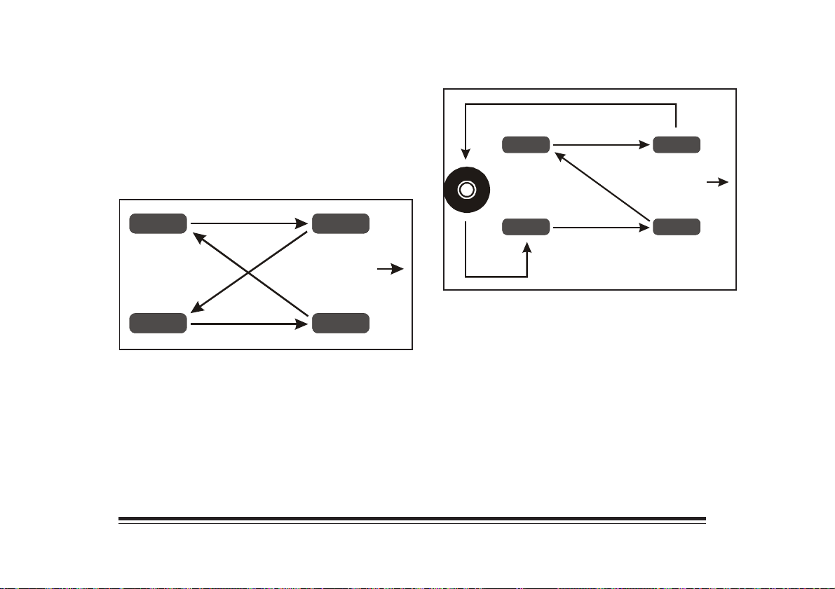
Tire Inspection and Rotation
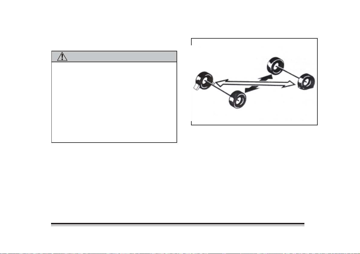
To make your tires last longer, have them inspected and
rotated at the recommended mileages. When rotating
your tires, always use one of the correct patterns shown
here.
After rotation, adjust the front and rear tire pressures.
4-15
Page 78
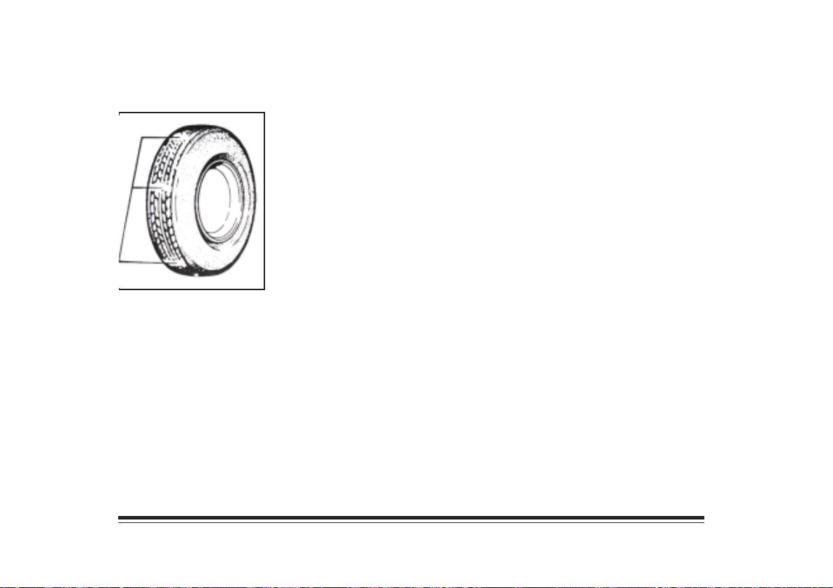
Tire replacement
One way to tell when it’s
time for a new tires is to
check the threadwear
indicators, which will
appear when your tires
have only 1.6 mm or less
of tread remaining.
You need a new tire if any of the following statements
are true:
• You can see the indicators at three or more places
around the tire.
• You an see cord or fabric showing through the
tire’s rubber.
• The tread or sidewall is cracked, cut or snagged
deep enough to show cord or fabric.
• The tire has a bump, bulge or split.
• The tire has a puncture, cut or other damage that
can’t be reapired well because of the size or location
of the damage.
When replacing tires, you should use the same size,
load range and construction type as the original tires on
the vehicle. If replacing only a single tire, it should be
paired on the same axle with the least worn tire of the
other three.
4-16
Page 79
CAUTION:
NOTICE:
Never dirve faster than the speed for which your tires
are rated, regardless of the legal speed limit. If you
anticipate driving your vehicle at high speeds
frequently and/or for prolonged periods of time, check
with your dealer for the proper type of tires to use for
your specific driving and weather conditions.
Vehicles left standing for an extended period of time
may be prone to exhibit flat spotting on the tires.
4-17
Page 80
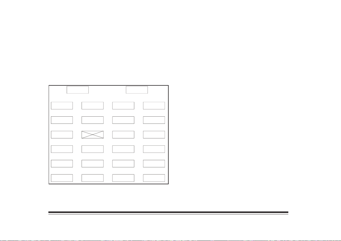
Fuses and Circuit Breakers
The fuse block is on the driver’s side of the instrument
panel. You can remove the fuses with a fuse extractor.
Look at the silver-colored band inside the fuse. If the
band is broken or melted, replace the fuse. Be sure you
replace a bad fuse with a new one of the identical size
and rating.
B
PWR
4WD
ELECT
SHIFT
FOG
F/PMP
RLY+2
1
9
2
0
2
1
2
2
2
3
2
4
WDO
RDO
BATT
TURN
B/U
BRAKEEST IGN
1
3
1
4
1
5
1
6
1
7
1
8
Fuse/Circuit Breaker ................................Usage
A ................................................... Power Door Locks
B ...................................................... Power Windows
1 ........................................ Stoplamp, Hazard Flasher
PWR
R/DEFRILLUM
ECM
BATT
ECM
ENG
A
AUX
IGN
FAN
PWR
ACCY
7
8
9
1
0
1
1
1
2
STOP
HAZ
HORN
DM
T/L
R. WASH
GAUGES
INJINJWIPERRADIO
HTR
A/C
1
2
3
4
5
6
Fuse/Circuit Breaker ................................Usage
2 ........................... Horn, Power Mirror, Interior Lamp
3 .............................. Parking Lamp, Underhood Lamp
4 .............................................. Cluster, Transmission,
Rear Wiper, Alarm Module
5 ...................................................... Injectors 2 and 4
6 ......................... Heater/Ventilation/Air Conditioning
Control Module
7 ............................................Auxiliary Power Outlets
8 ............................................................. Rear Defog
9 ............................................. Rear Wheel Anti-Lock,
Engine Control Module, Fuel Pump Relay
10 ............................. Ignition, Engine Control Module
11 ..................................................... Injectors 1 and 3
12 ............................................................ Cooling Fan
13 .................................................................... Radio
14 ................................................ Tail/Parking Lamps
16 ....................... Turn Signal Lamps, Back-Up Lamps
17 .................................................. Windshield Wiper
18 .................................. Vehicle Speed Sensor Buffer,
Rear Wheel Anti-Lock Module
21 .............................................................. Fog Lamps
22 ................................... Redundant Fuel Pump Relay
23 ..................................................................... Radio
24 ......................................... Electronic Spark Timing
4-18
Page 81
Bulb Replacement
Before you replace any bulbs, be sure that all the lamps
are off and the engine isn’t running. See “Replacement
Bulbs” in the Index for the proper type of bulb to use.
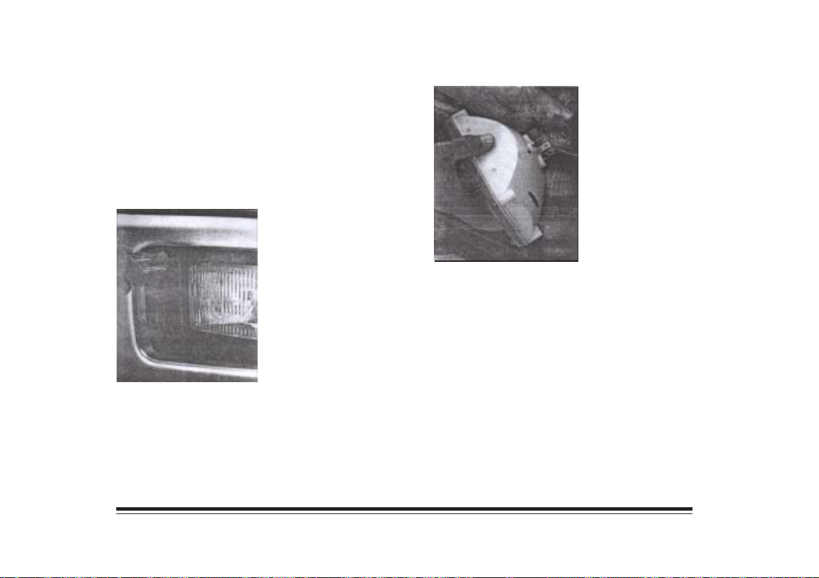
Headlamps
Sealed Beam Lamps
1. Remove the screws from
the headlamp retainer.
2. Pull the headlamp
out and remove the
retainer.
3. Unplug and remove the headlamps.
4. Plug in the new headlamp and put it in place.
5. Put the retainer on headlamp and install and
tighten the screws.
4-19
Page 82
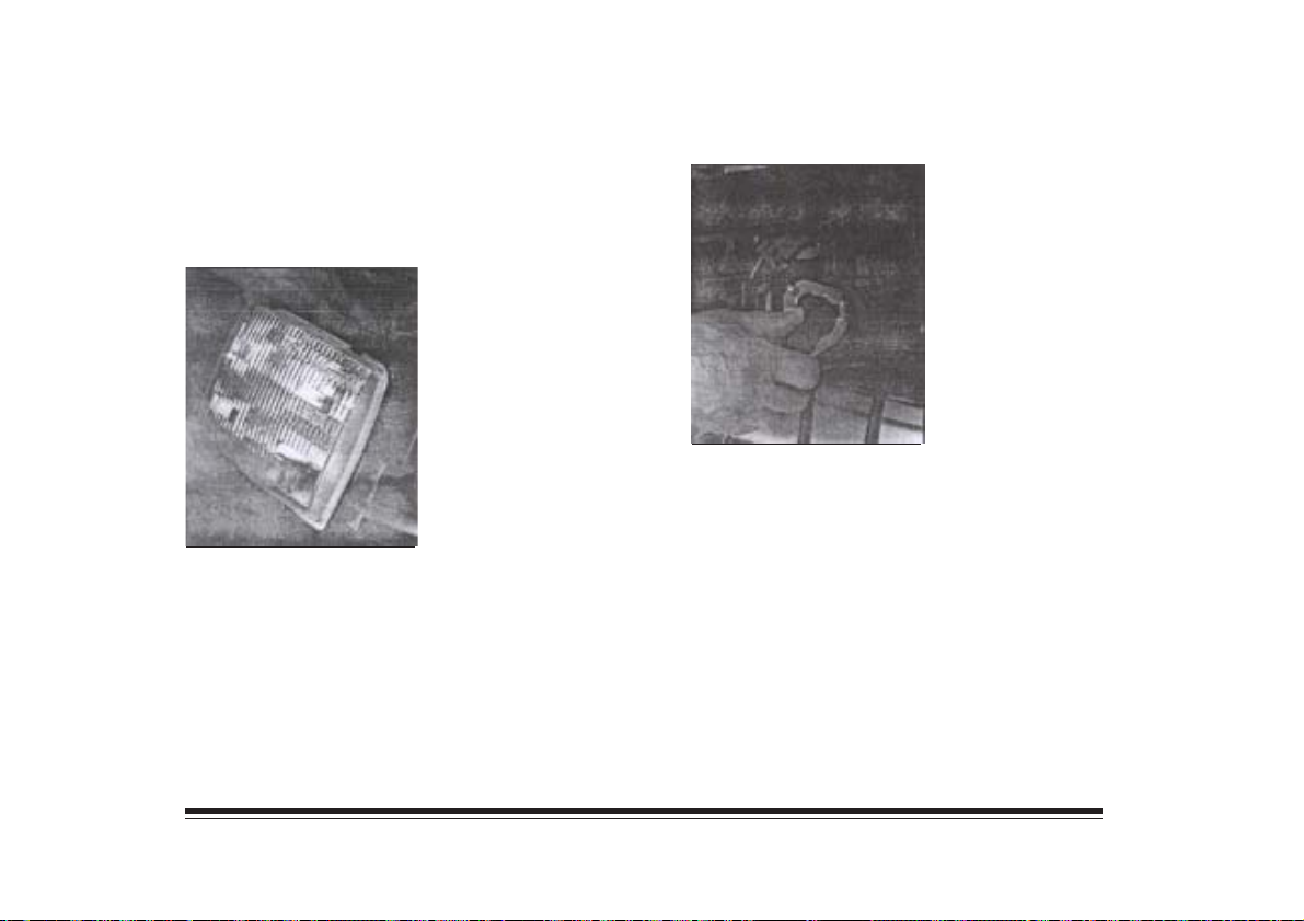
Composite Headlamps
1. Open the hood.
2. Remove the black protective caps from the
removal pins at the top the radiator support. Use a
hex socket to unscrew the pins.
3. Pull the headlamp lens
assembly out. (Some
vehicles may have
side-by-side bulbs).
4. Unplug the electrical connector.
5. Turn the bulb
counterclockwise to
remove it.
6. Put the new bulb into the headlamp lens assembly
and turn it clockwise until it is tight.
7. Plug in the electrical connector.
8. Put the headlamp lens assembly back into the
vehicle. Install and tighten the screws.
4-20
Page 83
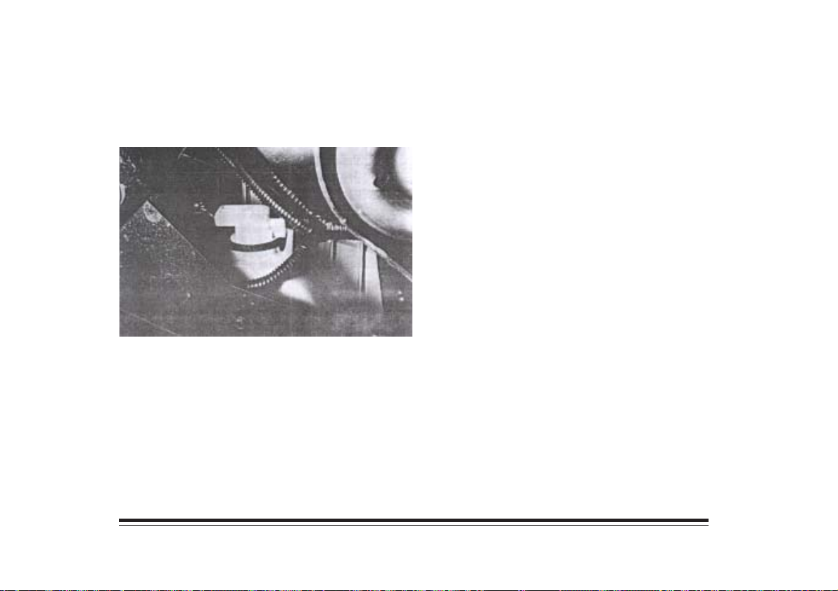
Turn Signal Lamps
If you have fog lamps, the fog lamp bracket must be
removed before you can replace the front turn signal lamps.
1. Reach under the bumper and behind the turn
signal assembly.
2. Turn the socket counterclockwise and pull it out.
3. Holding the base of the bulb, pull the bulb straight
out of the socket.
4. Push the new bulb into the socket until it clicks.
5. Put the socket back into the turn signal lamp
assembly and turn it clockwise until it locks in
place.
4-21
Page 84
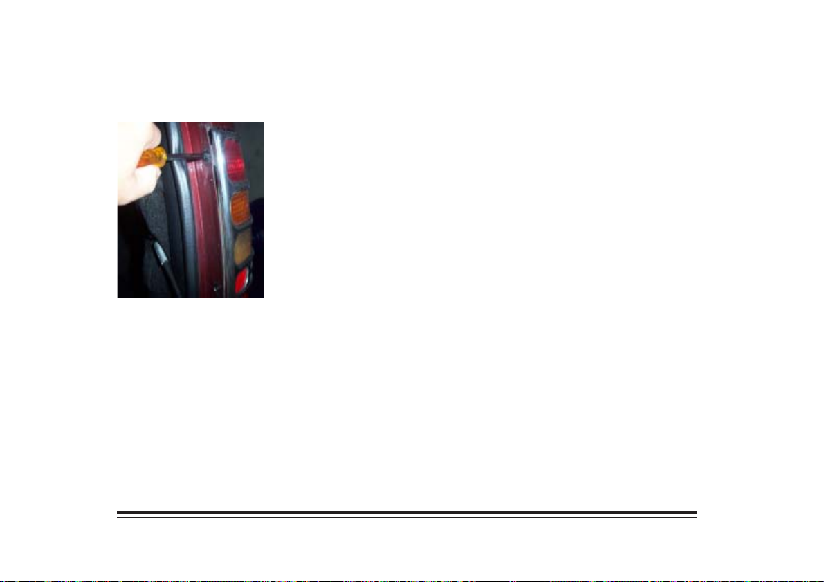
Taillamps
1. Open the endgate.
2. Remove the two
screws from the lamp
assembly.
3. Pull the assembly away from the fender.
4. Turn the socket counterclockwise to remove it.
Push the tab in while you turn the socket
counterclockwise.
5. Holding the base of the bulb, pull the bulb straight
out of the socket.
6. Push the new bulb straight into the socket until it
clicks.
7. Put the socket into the lamp assembly and turn the
socket clockwise until it locks in place.
8. Install the lamp assembly and screws.
9. Close the endgate.
4-22
Page 85
Replacement Bulbs
Lamps
Halogen Headlamps, Sealed Beam
Halogen Headlamps, Composite Low Beam
Halogen Headlamps, Composite High Beam
Tail and Stoplamps
Turn Signal Lamps
Capacities and Specifications
Vendor Identification Number
Type
Displacement
Firing Order
Horsepower
Thermostat Specification
Quantity
2
2
2
4
2
S
L4
2.2L
1-4-3-2
127 hp at 5200 rpm
82° C
Number
2EI
9006 HB4
9005 HB3
3057
3157 NA
H
L4
2.2L
1-4-3-2
138 hp at 5600 rpm
82° C
4-23
Page 86
Capacities (Approximate)
Cooling System* ..................................... 8.5 L
Crankcase* ............................................. 4.1 L
Fuel tank ................................................. 68 L
A/C Refrigerant (R-134a) .................. 0.795 kg
* After refill , the level must be checked.
Wheel Nut Torque
Aluminium Wheel (Static) ............ 85-135 N.m
Aluminium Wheel (Dynamic) ..... 100-130 N.m
Steel Wheel (Static) ...................... 95-145 N.m
Steel Wheel (Dynamic) ................ 110-140 N.m
Vehicle Dimensions
Wheelbase ........................................ 271.8 cm
Length (Rear bumper not included) ... 460.2 cm
Height .............................................. 167.4 cm
Width ............................................... 169.0 cm
Front Tread ....................................... 139.6 cm
Rear Tread ........................................ 137.5 cm
4-24
Page 87
Section 5 Problems on the Road
This section describes procedures to follow when
attempting to solve some of the problems that can occur
on the road. Pay close attention to the CAUTION and
NOTICE warnings to protect yourself and your vehicle.
Jump Starting
If your battery has run down, you may use another
vehicle with a 12-volt battery and some jumper cables
to start your vehicle.
NOTICE:
Ignoring these steps could result in costly damage
to your vehice.
CAUTION:
Batteries can hurt you. They can be dangerous
because:
• They contain acid that can burn you.
• They contain gas that cam explote or ignite.
• They contain enough electricity to burn you.
If you don’t follow these steps exactly, some or all
of these things can hurt you.
5-1
Page 88
1. Check the other vehicle. It must have a 12-volt
battery with a negative ground system.
NOTICE:
If the other system isn’t a 12-volt system with a
negative ground, both vehicles can be damaged.
3. Turn off the ignition on both vehicles. Unplug
unnecessary accesories plugged into the cigarette
lighter, or accessory power outlets, if you have this
option. Turn off all lamps that aren’t needed as
well as radios. This will avoid sparks and help
save both batteries. In addition, it could save your
radio!
2. Get the vehicles close enough so the jumper cables
can reach, but be sure the vehicles aren’t touching
each other. If they are, it could cause a ground
connection you don’t want. You wouldn’t be able
to start your vehicle, and the bad grounding could
damage the electrical systems.
You could be injured if the vehicles roll. Set the
parking brake firmly in each vehicle.
4. Open both hoods and locate the batteries. Find the
positive (+) and negative (-) terminals on each
battery.
CAUTION:
Using a match near a battery can cause battery gas
to explode. People have been hurt doing this, and
some have been blinded. Use a flashlight if you
need more light.
5-2
Page 89
5. Check that the jumper cables don’t have loose or
missing insulation. If they do, you could get a
shock. The vehicles could be damaged too.
Before you connect the cables, here are some basic
things you should know. Positive (+) will go to
positive (+) and negative (-) will go to negative (-)
or a metal engine part. Don’t connect positive (+)
to negative (-) or you’ll get a short that would
damage the battery and may be other parts too.
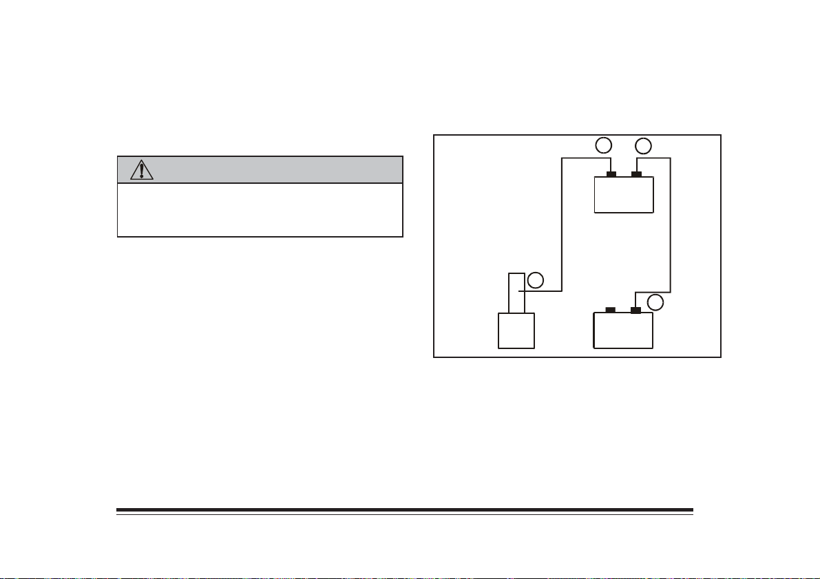
6. Connect the red positive (+) cable to the positive
(+) terminal of the vehicle with the dead battery.
7. Don’t let the other end touch metal. Connect it to
the positive (+) terminal of the good battery.
8. Now connect the black negative (-) cable to the
good battery’s negative (-) terminal.
Don’t let the other end touch anything until the next
step. The other end of the negative (-) cable
doesn’t go to the dead battery. It goes to a heavy
unpainted metal part on the engine of the vehicle
with the dead battery.
9. Attach the cable at least 45 cm away from the
dead battery, but not near engine parts that move.
The electrical connection is just as good there, but
the chance of sparks getting back to the battery is
much less.
10. Now start the vehicle with the good battery and
run the engine for a while.
5-3
Page 90
11. Try to start the vehicle with the dead battery. If it
won’t start after a few tries make sure all
connections are good. If it still won’t start, it
probably needs service.
CAUTION:
Fans or other moving engine parts can injure you
badly. Keep your hands away from moving parts
once the engines are running.
12. Remove the cables in reverse order to prevent
electrical shorting. Take care that they don’t touch
each other or any other metal.
2
3
+
--
B
1
4
A
A. Heavy Metal Engine part
B. Good Battery
C. Dead Battery
+
--
C
5-4
Page 91
Towing
NOTICE:
Don’t have your vehicle towed on the rear wheels,
unless you must. If you cannot avoid towing the
vehicle on the drive wheels, do not drive faster
than 50 km/h or farther than 80 km.
To help avoid damage to the vehicle once it is
secured to the tow truck:
1. Turn the ignition key to the OFF position
2. Have the steering whell calmped in a
straight-ahead position. Do not use the
vehicle’s steering column lock for this.
3. Shif the gear level to NEUTRAL (N).
4. Release the parking brake.
Towing Devices
Front and rear towing devices are attached on the left
side. Towing devices are rated at one half of the Gross
Vehicle Weight.
Make sure you use a 10 cm x 10 cm wood plank to
avoid damaging the frame of the license plate.
5-5
Page 92
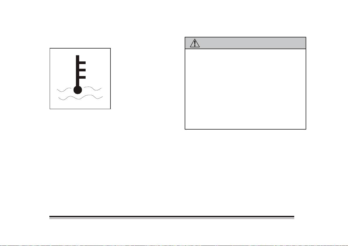
Engine Overheating
If you see or hear steam
coming from the engine,
stop and turn off the engine.
Do not open the hood until
the engine has cooled down.
CAUTION:
Steam from an overheated engine can burn you
badly, even if you just open the hood. Stay away
from the engine if you see or hear steam coming
from it. Just turn it off and get everyone away from
the vehicle until it cools down. Wait until there is
no sign of the steam or coolant before opening the
hood.
If you keep driving when your engine is overheated,
the liquids in it can catch fire. You or others could
be badly burned. Stop your engine if it overheats,
and get out of the vehicle until the engine is cool.
5-6
Page 93
NOTICE:
If your engine catches fire because you keep driving
with no coolant, your vehicle can be badly
damaged.
If the coolant temperature gage shows an overheat
condition, but you see or hear no steam, try this for a
minute or so:
1. Turn off your air conditioner and turn on your heater
to full hot at the highest fan speed. Open the window
as necessary.
2. If you’re in a traffic jam, shift to NEUTRAL (N);
otherwise, shift to the highest gear while driving.
If you no longer have the overheat warning, you can
drive. Just to be safe, drive slower for about 10
minutes. If the warning doesn’t come back on, you can
drive normally.
If the warning continues, pull over, stop and park your
vehicle right away.
You may decide not to lift the hood but to get service
help right away.
If you decide to open the hood and the coolant inside
the coolant tank is boiling, don’t do anything else until
it cools down.
5-7
Page 94
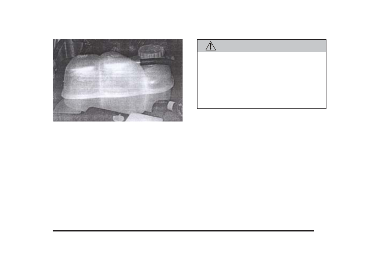
The coolant level should be at the COLD mark. If it
isn’t, you may have a leak in the radiator hoses, heater
hoses, radiator, water pump or somewhere else in the
cooling system.
CAUTION:
Heater and radiator hoses, and other engine
parts, can be very hot. Don’t touch them. If you
do, you can be burned.
Don’t run the engine if there is a leak. If you
run the engine, it could lose all coolant. That
could cause an engine fire, and you could be
burned. Get any leak fixed before you drive the
vehicle.
If you haven;t found a problem yet, but the coolant
level isn’t at the ADD mark, add a 5-/50 mixture of
clean water and extended life coolant at the coolant
recovery tank. (See “Engine Coolant” in the Index for
more information).
When the coolant in the coolant recovery tank is at the
COLD mark, start your vehicle.
5-8
Page 95
Changing a Flat Tire
CAUTION:
Changing a tire can cause an injury. The vehicle
can slip off the jack and injure you or other people.
Avoid further tire and wheel damage by driving
very slowly to a level place to change the tire.
Turn on your hazard warning flashers. To help
prevent the vehicle from moving while changing
the tire:
1. Shift into FIRST (1) or REVERSE (R).
2. Set the parking brake firmly.
3. Turn off the engine.
4. Put blocks at the front and rear of the tire
farthest away from the one being changed.
5-9
Page 96
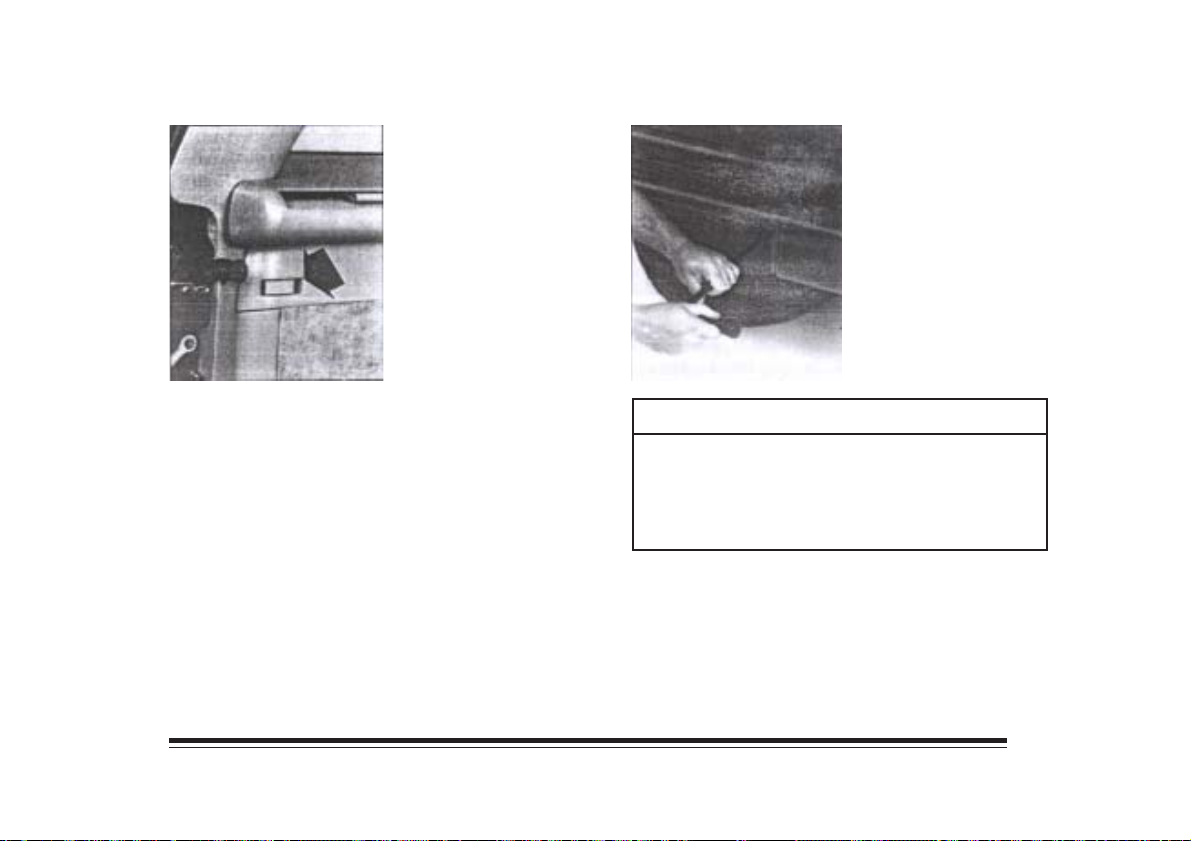
3. To remove the
underbody-mounted
spare, insert the
chisel end of the
wheel wrench, on an
angle, into the gole
in the rear bumper.
Be sure the chisel
end of the wheel
wrench connects into
the hoist shaft.
1. To remove your jack cover, pull up on the latch at
the end of the cover, near the endgate and the latch
on the top of the cover.
2. Remove the wheel blocks, jack and wheel wrench.
NOTICE:
Never remove or restow a tire from/to a stowage
position under the vehicle while the vehicle is
supported by a jack. Always tighten the tire fully
against the underside of the vehicle when
restowing.
5-10
Page 97
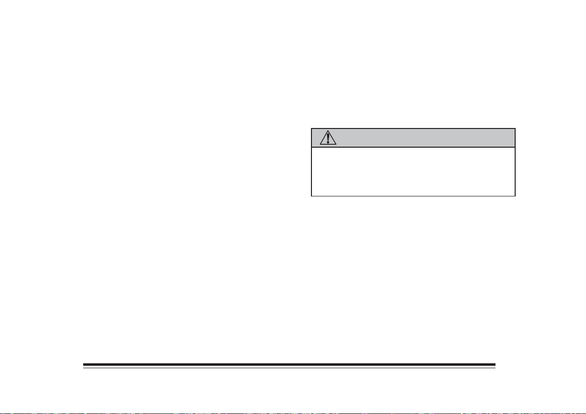
4. Turn the wheel wrench counterclockwise to lower
the spare tire. Keep turning the wheel wrench
until the spare tire can be pulled form under the
vehicle.
5. When the tire has been completely lowered, tilt
the retainer at the end of the cable and pull it
through the wheel opening. Pull the tire out from
under the vehicle.
6. If your vehicle has wheel nut caps, remove them
with the wheel nut wrench. The plastic hub cap
has imitation wheel nuts which the wheel nut
wrench will not fit. Do not try to remove these
nuts.
7. Pry the hub cap off with the flat end of the wheel
wrench.
8. Loosen the wheel nuts, but do not remove them
yet.
9. Place the jack under the jacking point nearest the
flat tire.
CAUTION:
Getting under a vehicle when it is jacked up is
dangerous. If the vehicle slips off the jack, you
could be badly injured or killed. Never get under
a vehicle when it is supported only by a jack.
5-11
Page 98
NOTICE:
Raising your vehicle with the jack improperly
positioned will damage the vehicle or may allow
the vehicle to fall off the jack. Be sure to fit the
jack lift head into the proper location before
raising tour vehicle.
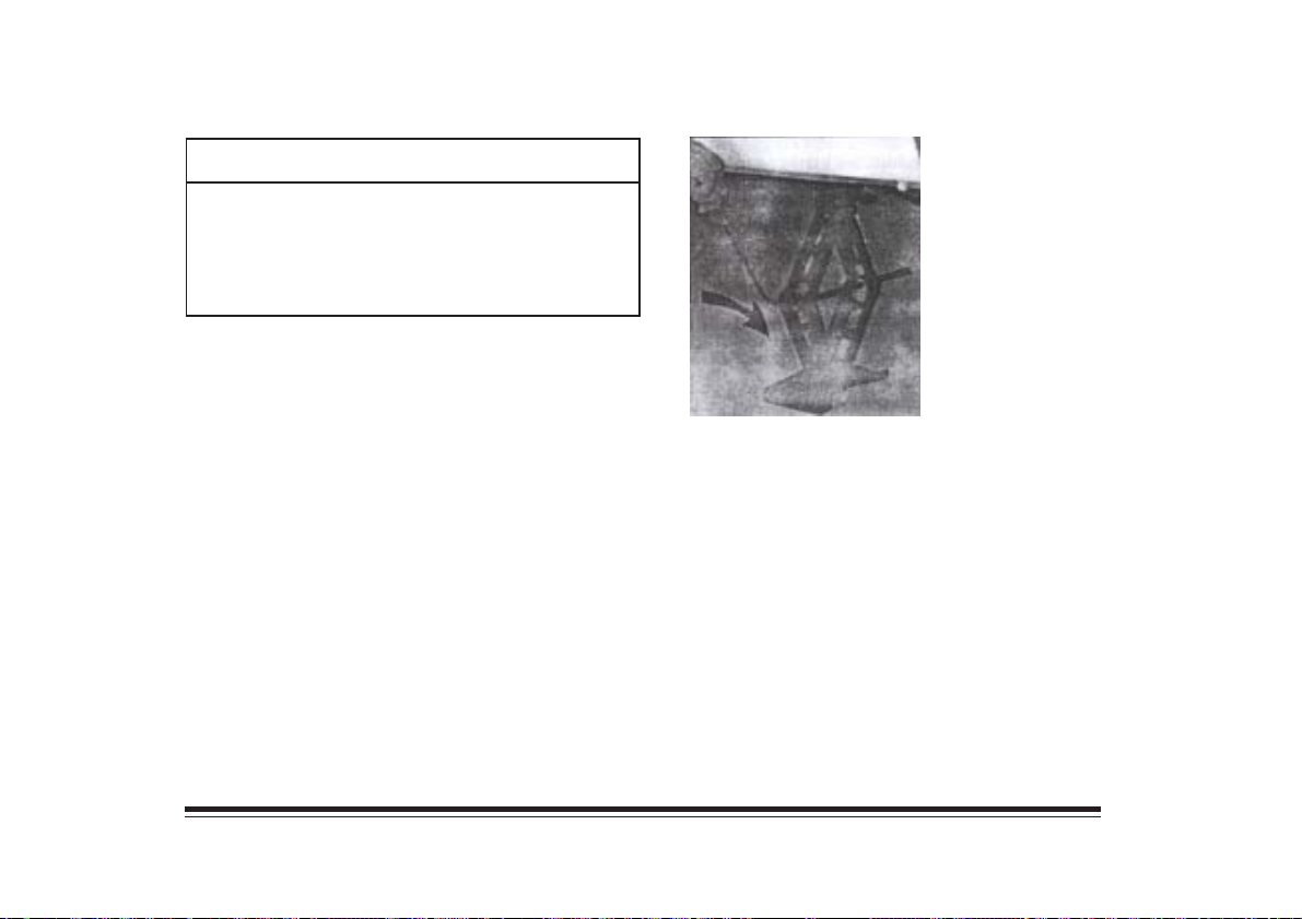
10. Raise the jack until
the jack head fits
fimly into the notch.
Then raise the
vehicle off the
ground until there is
room for the spare
tire to fit.
11. Remove all the wheel nuts and take off the flat
tire.
5-12
Page 99
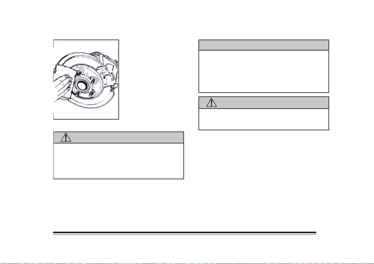
12. Remove any rust or dirt
from the wheel bolts,
mounting surfaces and
spare wheel.
CAUTION: (Continued)
wheel, remove any rust or dirt from the places
where the wheel attaches to the vehicle. In an
emergency, you can use a cloth or a paper towel
to do this; but be sure to use a scrapper or wire
brush later, if you need to, to get all the rust or
dirt off.
CAUTION:
Never use oil or grease on studs or nuts. If you do,
the nuts might come loose. Your wheel could fall
off, causing a serious accident.
CAUTION:
Rust or dirt on the wheel, or on the parts to
which it is fastened, can make the wheel nuts
become loose after a time. The wheel could come
off and cause an accident. When you change a
CAUTION: (Continued)
13. Place the spare on the wheel mounting surface.
5-13
Page 100
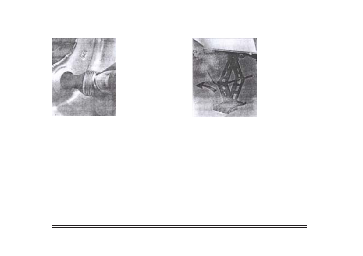
14. Install the wheel nuts
with the rounded end
toward the wheel.
Tighten each nut by
hand until the wheel is
held against the hub.
15. Lower the vehicle.
5-14
 Loading...