

Page 1

©
S
A
u
A
M
G
e49
Pre
p
I
n
C
o
mod
e
p
res
e
U
T
h
•••
H
W
T
h
give
n
•••
•
S
W
B
e
JRE
‘jav
a
b
e i
nTh
b
e d
o
http:
/
4958
M
a
emiconductor Com
p
gust 31, 2011
IS4
9
tting s
t
587 Ev
a
ared by: Ind
troductio
ngratulations,
h
m demonstrat
i
nt document
w
npack yo
u
e evaluation ki
•
2 AMIS-
4
p
lugged on
D
•
2 USB se
r
•
This man
u
W
requir
e
e material nec
hereunder:
•
1 PC run
n
free.
•
2 AMIS-
4
•
2 USB ca
b
•
2 mains
c
connector.
connect to
L
require
fore starting t
h
6.13 or highe
r
.com/getjava’.
stalled automa
t
e User Interfa
c
wnloaded fro
m
/www.onsemi.
7
ins connection
onents Industries, L
L
– Rev. 008
587
arted
w
luatio
n
ustrial ASSP
n
ere is the AM
I
on kit from O
N
ill help you to
r materi
a
t contains the
fo
9587 evaluatio
aughter Boar
d
ial cables
al
ments
essary to run
a
ing Windows
9587 evaluatio
les
ables. To con
n
(not included)
ine and Neutr
a
ments
e PLC UI, ma
k
is installed
o
On MS Wind
o
ically.
e Software an
d
:.
com/PowerSol
u
D
a
C, 2011
ith th
e
kit
- ON Semic
o
S-49587 pow
e
Semiconduct
o
get the kit wor
k
l
llowing elem
e
n boards (Mot
h
)
communicati
o
XP or higher
w
n boards
ect to the M
o
. Please take
l.
e sure the Jav
a
r download a
n
ws based plat
f
most recent d
o
tions/product.
ughter Board
Mothter Boar
AMIS
-
nductor
r line carrier
r, Inc.. The
ing quickly.
nts:
er Board and
n with the ki
t
ith 2 USB p
o
ther Board m
care to corre
c
Runtime Eng
d install it fr
o
orms the JRE
w
cumentation c
a
do?id=AMIS-
USB con
n
d
1
is
rts
ain
tly
ine
m
ill
n
c
odo
I
MdeDi
o
f
m
ection
AMIS-49587
RESET
The USB p
o
nverter. A de
d
wnload it fro
m
http://www.ft
d
Setting u
Once you get
t
Step 1:
Connect the b
o
Step 2:
Connect the P
L
Step 3
:
Power the PL
C
PORTANT
monstration
sconnect the
b
it. Be sure
anipulate it.
USB con
n
Mains conne
c
http://onse
m
rt communic
a
icated USB
d
the FTDI we
b
ichip.com/FT
D
p the har
d
he above liste
d
th PLC MOD
E
C MODEM
m
MODEM.
REMARK:
2
board. Kee
p
oard from t
h
that only tr
a
ection
tion
Publication
i.com
tes with a
F
river is need
e
site:
rivers.htm.
ware
elements, you
M’s to the US
ains plug to th
e
30V mains
a
the board
e mains befo
r
ained people
Order Number
:
AMIS-49587
TDI serial
U
d for this. Y
o
need to:
B ports of the
P
mains.
re present o
n
in a safe
e any manipu
l
are authoriz
e
ART
u can
C.
the
area.
ation
d to
Page 2

AMIS-49587
http://onsemi.com
2
Setting up the software
The kit is delivered with a CDROM. Insert the CDROM in the
CD drive. For MS Windows based platforms, an installer
application is available: ONSemiPLCInstall.exe. The installer
application checks if the required Java Runtime Engine is installed.
If it is not, the installer will start downloading it from the Sun
website and install it.
For non MS Windows based platforms see SW requirements.
When the required Java Runtime Engine is installed, installation
of the ON Semiconductor PLC Modem application will proceed.
1.4.7
| AMIS49587 GUI application note.pdf
| plcui.chm
| PlcUi.jar
| rxtxSerial.dll
| Slave 7.1.plc.xml
| Master 7.1.plc.xml
| Spy 7.1.plc.xml
|
\---lib
AbsoluteLayout.jar
appframework-1.0.3.jar
RXTXcomm.jar
swing-worker-1.1.jar
PlcUi.jar is the main application, ‘AMIS49587 GUI application
note.pdf’ is this manual and ‘Master 7.1.plc.xml’ and ‘Slave
7.1.plc.xml’ are MODEM configuration files. Plcui.chm is the
source code documentation.
All other files are supporting libraries.
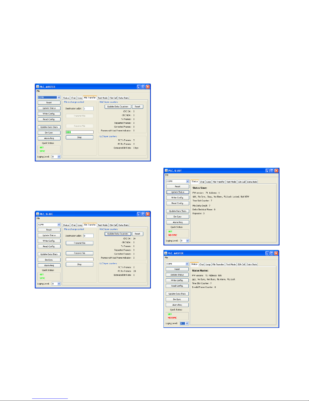
Running the Graphical user interface
The graphical user interface consists of 3 types of windows. The
main window allows the user to open a configuration file for a PLC
MODEM and implements a log of messages that traces user
activities and MODEM events. This event log can be cleared or
saved into a text file from the file menu. When a correct MODEM
configuration file is opened, a new window will appear,
implementing a user interface tailored to the type of configuration
that is opened (master, slave, monitor or spy). Master and slave
windows look very similar. Only the area where the MODEM’s
status is displayed is different. The application limits the number
of master or slave windows to 6.
The logging level can be set from 0 to 3 to choose the level of
detail of the log messages. Level 3 gives most details. The status
fields of the master and slave windows will update when the button
‘Update Status’, Reset’ or ‘Write Config’ are clicked or,
automatically, when the status pane is activated.
Figure 1 Main Window
Figure 2 Master Window
The MODEM’s can be forced to disconnect (lose
synchronization) by clicking the ‘De-sync’ button. The ‘Reset’
button shall be clicked when the modem is in an unknown state or
the user would like to start from a not configured MODEM.
When parameters, listed in the configuration file and exposed in
the GUI are changed, these changes can be saved into a new
configuration file by picking ‘Save Configuration’ from the master
or slave window file menu, or by pressing ‘CTRL-S’ (for now,
only the communication port and the MAC layer filter setting can
be changed from the GUI).
Note that all MODEM’s settings can be modified by editing the
configuration file in a text editor. The configuration file is an
XML file. Each MODEM parameter is encapsulated in parameter
name and value keywords. All parameters are to be coded in
hexadecimal numbers. Below is an example that shows how the
local MAC address is set to 0x555:
<LocalMac>
<Bits>16</Bits>
<Value>555</Value>
<Note>Number within FIMA to LIMA range</Note>
</LocalMac>
Only the value between <Value> and </Value> should be changed.
New settings can be activated by loading the new configuration file
from the main window.
The current PLC GUI implements a simple chat, data loop or file
transfer application between a master and a client. Before being
able to exchange data, one master configuration and at least one
slave configuration needs to be opened from the main window on
one or more PC’s.
To start communication, the following steps need to be executed
for both the master and the slave(s) windows:
Common to all 3 communication examples are:
1) Pick the serial port that is connecting the PLC master
MODEM. Only the serial communication ports available in
the PC are listed. Success or failure to open the chosen
communication port can be monitored in the log that is
displayed in the main window.
2) Click the ‘Reset’ button to bring the MODEM into a
known, not configured state.
3) Click the ‘Write Config.’ button to send the configuration
parameters to the MODEM. Check the main window log to
find out if this step completed without errors.
Page 3
AMIS-49587
http://onsemi.com
3
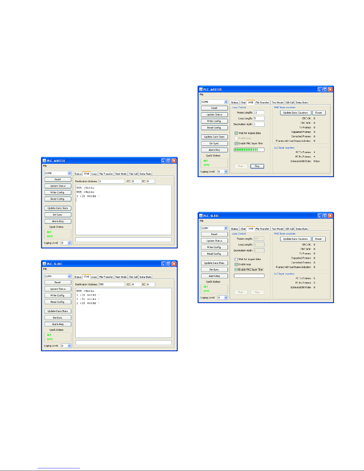
Chat Application
When the Chat application is chosen:
1) Type the address of the MODEM to whom you would like
to send a message in the ‘Destination Address’ field. The
MODEM address is coded in the configuration file and
displayed in the status area.
2) Type a message in the bottom single line text field and hit
‘Enter’.
When the first message is sent from the master window, the
slave will synchronize with the master and display the message it
received in its text frame above its text input field. Follow the log
in the main window to check if all goes well. The first message
always needs to be initiated from the master window. When the
slave is properly synchronized, messages can be transmitted from
slave to master.
Depending on the previous state of the master, the first message
may fail to deliver. Initiate the send request again.
Figure 3 Master Window, configured with chat trace
Figure 4 Slave Window with chat trace
Data Loop Application
In the data loop application a constant data frame is sent from
one node (master or slave) and is received by the addressed node.
The receiver node can be configured to send the data back to the
sending node, implementing a data loop.
To setup a data loop, make sure the configuration file is written
to the MODEMs and in one node:
1) Check the ‘Enable loop’ checkbox to make this node into a
receiver and loop node.
In the window of the transmitter node:
2) Enter the frame length. The maximum is 247 bytes, the
minimum is 13 bytes.
3) Enter the number of times the data needs to be transmitted
4) Enter the destination address
5) Check the ‘Wait for looped data’ checkbox to make sure the
transmitter doesn’t send a new frame before receiving the
looped data.
6) Click the start button
Figure 5 Initiator node of the data loop
The LLC layer counters indicate the number of transmitted and
received frames. The approximate bit rate is calculated at the end
of transmit and receive sequence.
Figure 6 Receiving and looping node
By clicking the ‘Update Data Counters’ button, the MAC layer
counters that are kept in the MODEM are retrieved. The number
of received frames is the total of ‘CRC OK’ and ‘CRC NOK’
frames. All counter values can be reset by clicking the ‘Reset’
button.
The current implementation of the data loop does not check for
errors in the looped data.
Page 4
AMIS-49587
http://onsemi.com
4
File Transfer Application
The file transfer application sends a file from the transmitter to
the receiver. Before initiating transmit, the addressed node should
be ready to receive the file. Click on ‘Receive File’ to open a file
save dialog box. Enter the file name. The receiver node is now
waiting for the complete file to arrive. On the transmitter node,
click the ‘Transmit File’ button. A file open dialog box will
appear. Choose the file to be sent. Transmit will start
immediately.
Figure 7 Node transmitting a file
Transmit or receive can be aborted at any time by clicking the
‘Stop’ button.
The file transfer application can be used to implement a BER
test. Bit error rate can be calculated by comparing the received file
with the original (not implemented by this application).
Figure 8 Node receiving a file
Special Scenarios
Repetition with Credit and Time Slot Counter change.
When the configuration for a server is setting the MODEM as a
repeater: set 1,2 or 3 in the Repeater section of the xml
configuration file, the MODEM will repeat messages addressed to
a different MODEM only when the current credit field in the data
frame is higher than 0
…
<Repeater>
<Bits>2</Bits>
<Value>3</Value>
<Note>
0 Never Repeater or Mode=Master,
1 Always Repeater,
2 Not Repeater (accept frame ISACall),
3 Repeater (accept frame ISACall)
</Note>
</Repeater>
The time slot counter is communicated to an external processor
or to the GUI by means of the time slot field in the status message.
The time slot counter should be used by the external processor to
block data transmission when repetition is ongoing.
The default value of the time slot counter is 7 (maximum
number of repetitions is 8: from 0 to 7) and indicates that the
communication channel is free for transmission. When the
MODEM is repeating a message, it is decrements it’s time slot
counter every time the MODEM autonomously sends the message
on the power line. At the same time the MODEM decrements the
current credit field in the frame.
This process can be partially visualized using the GUI. 3
MODEMS are needed:
One with master configuration
One with slave configuration
One with Spy configuration
Steps to follow, after all MODEMS have been configured:
1) Make sure the Spy window is set to logging level 1 and
master to level 3.
2) Make sure the master/slave are not synchronized
3) Check the status of both MODEMS and witness that the
time slot counter is in both 7.
4) Open the chat window in master
5) Set CC (Current Credit) and IC (Initial Credit) to 2
6) Set the Address field to an address that is different (!!)
from the slave address
Page 5

Y
o
time
0 or
1
Resp
W
agai
n
repe
a C
will
repe
a
the f
r
MO
N
MO
NMON
0
6
7MONMONMONMON
0
6
7MONMONMON
MO
N
0
6
7MONMONMONcorMON
7) Send a m
e
u will notice
t
slot counter in
, depending o
n
onse.
hen you upda
t
set at 7 beca
u
ted 2 times alr
e
heck the log t
h
be visible 3 t
i
ted by the sla
v
ame is lowere
d
ITOR:15:43
:
ITOR:15:43
:
ITOR:15:43
:
0 6c 6c 48
8 9 a b c
ITOR:15:43
:
ITOR:15:43
:
ITOR:15:43
:
ITOR:15:43
:
0 6c 6c 44
8 9 a b c
ITOR:15:43
:
ITOR:15:43
:
ITOR:15:43
:
ITOR:15:43
:
0 6c 6c 40
8 9 a b c
ITOR:15:43
:
ITOR:15:43
:
ITOR:15:43
:
rectly
ITOR:15:43
:
ssage from th
e
hat both MO
D
the slave wind
o
how fast and
w
e the slave sta
se by now th
e
ady.
e spy has gen
e
mes: one tim
e
e. Also check
each transmis
47:745:Spy
47:854:Spy
S
47:854: Re
c
55 50 6 15
d e f 10 1
1
47:854: Sp
y
47:854: Al
a
47:964:Spy
S
47:964: Re
c
55 50 6 15
d e f 10 1
1
48:073: Sp
y
48:073: Al
a
48:183:Spy
S
48:183: Re
c
55 50 6 15
d e f 10 1
1
48:183: Sp
y
48:183: Al
a
48:292: Sp
y
48:292: Re
c
master.
EMS synchr
o
w is different
w
hen the slave
tus, the time sl
received fra
m
rated. The tr
a
from the m
a
that the curre
n
sion.
Synchroniz
a
ubFrame
eived SDU:
41 41 41 41
12 13 14 1
No Alarm
F
rm pattern:
ubFrame
eived SDU:
41 41 41 41
12 13 14 1
No Alarm
F
rm pattern:
ubFrame
eived SDU:
41 41 41 41
12 13 14 1
No Alarm
F
rm pattern:
No Sub F
eived SDU:
A
nize and that
from 7. It will
sent out the s
y
ot counter will
e will have b
e
nsmitted mess
a
ster and 2 ti
m
t credit counte
r
tion Found,
41 1 2 3
4
5 39 f6 b7
ound
2 db
41 1 2 3
4
5 a3 8a 31
ound
2 fb
41 1 2 3
4
5 d2 f9 e6
ound
1 26
rame recei
v
MIS-49
5
http://onsemi.c
o
5
the
be
nc.
be
en
ge
es
in
5
5
5
ed
a
pdePLquthGU
to
ei
t
re
s
eBu
87
m
Sending an
a
When a slave
plication laye
r
cide to send
o
C master ap
p
erying more i
is behavior in
u
1) Make s
u
configur
a
<
NbAla
r
<Bi
t
<Va
l
<No
t
<
/NbAl
a
2) Open ma
s
3) Make su
r
couple o
f
chat appl
i
4) Hit the al
a
5) Hit the st
a
6) Witness t
h
Update exp
e
Not all MOD
E
I. To chang
e
be edited wit
h
her close the
m
load the new c
o
Note that aft
e
nd to the M
O
tton.
larm
encounters a
n
on the exter
n
ut an alarm n
o
lication layer
nformation on
sing the GUI:
re the Nb
A
tion file is set
t
m>
s>4</Bits>
ue>8</Value
e>Number of
Alarm, 0
functiona
rm>
ter and slave c
e master and s
characters fro
m
cation.
rm request bu
t
tus update but
t
at the status c
h
rt settings
M configurati
all parameter
a regular text
e
aster/slave/sp
y
nfiguration fr
o
r reloading th
e
DEM by cli
c
alarm condit
i
al controller,
tification on
t
will start sen
d
the alarm co
n
larm param
e
o 8.
>
repetition
for Disable
lity</Note>
onfiguration.
lave are synch
r
the master t
o
ton on the sla
v
on on the mas
t
anges from n
o
on settings ca
n
s, the configur
a
ditor. To acti
v
node frame a
n
m the node wi
n
configuratio
n
king ‘reset’
a
on, managed
b
the applicatio
n
he power line
.
ing out data
f
dition. To
m
ter in the
s of a Phy
Phy Alarm
onized by sen
d
the slave, usi
n
e window.
er window.
alarm to alar
m
be altered fr
o
tion .xml file
ate the new s
e
d open a new
o
dow file men
u
it still needs
nd ‘Write C
o
y the
may
The
rames
onitor
slave
ing a
g the
.
m the
needs
ttings
ne or
.
to be
nfig.’
Page 6
AMIS-49587
http://onsemi.com
6
All MODEM parameters are listed in the xml configuration file
as follows:
<parameter string representation>
<Bits> the number of bits</Bits>
<Value> the parameter value </Value>
<Note> Some notes on the parameter </Note>
</parameter string representation>
The parameter string representation and the number of bits
should not be modified!
All number fields in the xml configuration file are to be written
in hexadecimal numbers without prefix like ‘0x’.
Send and receive ISA call pattern
ISA or Repeater Call is part of the CIASE protocol. The purpose
of the RepeaterCall service is to adapt the repeater status of server
systems depending on the topology of the electrical network. It
allows the automatic configuration of the repeater status on the
whole network. In the RepeaterCall mode, the client and the
servers transmit short frames – two bytes long each – and measure
the level of the signal to determine if a server system should be a
repeater or not.
The ISA call request has 2 parameters:
1) Time slot: This pattern is transmitted on a pre definded
timeslot:
a. The local MAC address when the slave is not
having address yet or has address NEW.
b. A random time slot between Max_Adr_MAC and
Max_Adr_MAC + (Nb_Tslot_For_New * 21).
Max_Adr_MAC and Nb_Tslot_For_New are
transmitted to the servers in a regular
MA_DataRequest and are kept by the application
layer. Note that if Nb_Tslot_For_New is 0, the
servers in NEW state should not participate in the
ISA call.
2) Reception_Threshold or level represents the signal level
in dBµV threshold. The default value is 104.
The participation of the servers in the repeater call process and
the effect of the process on their repeater status depend on the
repeater management variable and the signal level heard:
1) Servers configured as never repeater do not participate:
they do not transmit during their sub-timeslot and their
repeater_status is not affected;
2) Servers configured as always repeater participate: they
transmit during their timeslot but their repeater_status is
not affected;
3) Servers configured as dynamic repeater participate: they
transmit during their sub-timeslot, if they have not heard
a signal before from the client or from any servers, which
is above the reception threshold. If during the whole
repeater call process, a server does not hear a signal from
the client or from other servers, which is above the
reception threshold, then its repeater status will be
TRUE: the server will repeat all frames. If a server hears
a signal from the client or from other servers, which is
above the reception threshold, then its repeater status will
be FALSE: the server won't repeat any frames. NOTE If
each server configured as dynamic repeater hears a
signal, which is above the reception threshold this means
that they are all close to a client, and no repetition is
needed. So, none of them will become a repeater.
The embedded SW in our PLC silicon only issues the error
message LM_SE, or syntax error at MAC level when:
1) The MODEM is master(client) and the transmission
position is different from 1.
2) The MODEM is slave(server) and the transmission
position is 0 or 1.
The embedded SW in our PLC silicon issues the error message
LM_TU1, or NEG at the MAC level when:
1) Slave MODEM is set to 'never repeater'
2) The MODEM is busy handling other events. In this case
the ISA call should be repeated until success.
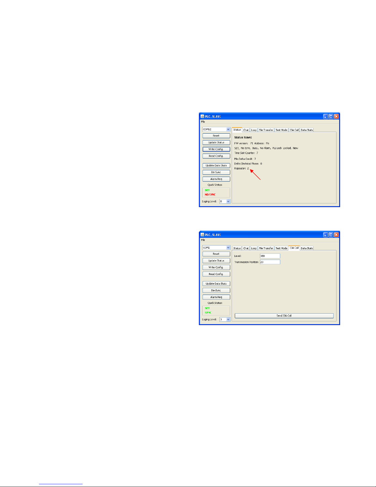
Build a setup with one master (client) and one slave (server).
Make sure the server or slave configuration sets the Repeater
mode to 2: No repeater, but support for ISA call, or dynamic
repeater. Open a slave or server node window.
Synchronize master and slave by typing few lines on the master
Chat application, use slave MAC address or any other.
Open the ISA call tab. Enter any timeslot different from 1 and
any level. Set the logging level to 3.
Hit the ‘Send ISA Call’ button many times quickly after each
other until the logging shows an ISA confirm message with data ff.
SLAVE :09:50:50:625: Sending ISAREQUEST
SLAVE :09:50:50:703: Message was sent to MODEM
SLAVE :09:50:50:703: Received message from
MODEM: 62 0
SLAVE :09:50:50:703:IsaConfirm
SLAVE :09:50:50:781: Sending ISAREQUEST
SLAVE :09:50:50:843: Message was sent to MODEM
SLAVE :09:50:50:843: Received message from
MODEM: 62 0
SLAVE :09:50:50:843:IsaConfirm
SLAVE :09:50:50:906: Sending ISAREQUEST
SLAVE :09:50:50:984: Message was sent to MODEM
SLAVE :09:50:51:203: Received message from
MODEM: 62 ff
SLAVE :09:50:51:203:IsaConfirm
Page 7
AMIS-49587
http://onsemi.com
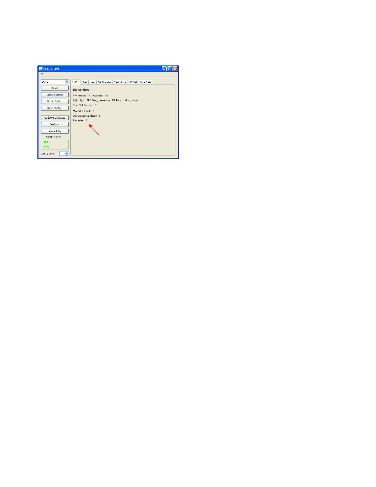
7
Go back to the status pane on the slave node and witness that the
repeater status has changed from no repeater to repeater because
the server did not receive any ISA call pattern from any other
MODEM.
Note that the MODEM may respond negative (62 00) many
times because its physical layer is busy. The management
application should send ISA call request in polling for success
(62 ff) loop.
Other scenarios can be tested where level and transmission
position is set depending on system topology in a multi-server
network with proper line attenuators.
Page 8

©
S
A
u
No
t
O
N
any
p
arisi
n
“Typ
i
oper
a
nor t
h
inten
Buy
e
and
d
asso
c
Opp
o
P
LI
T
Liter
a
P.O.
Pho
n
Fax:
Emai
emiconductor Com
p
gust 31, 2011
es
Semiconductor
a
roducts herein. S
g out of the appli
c
cal” parameters
w
ting parameters, i
n
e rights of others
.
ded to support or
r purchase or use
S
istributors harml
e
iated with such
u
rtunity/Affirmative
UBLICATION
O
ERATURE FULFI
L
ture Distribution Ce
n
Box 5163, Denver,
C
e: 303-675-2175 or
303-675-2176 or 80
0
l: orderlit@onsemi.
c
onents Industries, L
L
– Rev. 008
nd are registe
r
CILLC makes no
w
ation or use of an
hich may be prov
i
cluding “Typicals
”
SCILLC products
sustain life, or for
CILLC products f
o
ss against all clai
m
nintended or una
u
Action Employer.
RDERING IN
F
LMENT:
ter for ON Semicon
d
olorado 80217 US
A
800-344-3860 Toll
F
-344-3867 Toll Fre
e
om
C, 2011
ed trademarks of
S
arranty, represent
a
y product or circu
i
ded in SCILLC da
t
must be validate
d
are not designed,
any other applicat
i
r any such uninte
n
s, costs, damag
e
thorized use, eve
n
This literature is s
u
ORMATION
uctor
ree USA/Canada
USA/Canada
emiconductor Co
m
tion or guarantee
t, and specifically
a sheets and/or s
for each custome
r
intended, or autho
r
on in which the f
a
ded or unauthoriz
e
s, and expenses,
a
if such claim all
e
bject to all applica
N. Ameri
c
Toll Free
Europe,
Support:
Phone: 4
2
Japan C
u
Phone: 8
1
8
ponents Industri
e
regarding the suit
a
disclaims any and
pecifications can
a
application by cu
s
ized for use as co
m
ilure of the SCILL
C
d application, Bu
y
nd reasonable att
o
ges that SCILLC
w
ble copyright laws
an Technical Sup
p
USA/Canada
Middle East a
n
1 33 790 2910
stomer Focus Cen
t
-3-5773-3850
s, LLC (SCILLC).
S
bility of its produc
t
all liability, includ
i
nd do vary in diff
e
tomer's technical
e
ponents in syste
m
product could cr
e
er shall indemnify
a
rney fees arising
w
as negligent reg
a
and is not for resal
e
ort: 800-282-9855
d Africa Techni
ter
CILLC reserves th
e
t
s for any particul
a
ng without limitati
o
rent applications
xperts. SCILLC d
o
s intended for su
r
ate a situation w
h
nd hold SCILLC a
out of, directly or
rding the design
in any manner.
cal
ON Se
m
Order L
i
For add
Sales
R
Publication
right to make ch
a
r purpose, nor do
e
n special, conseq
and actual perfor
m
es not convey an
y
gical implant into
t
ere personal injur
y
nd its officers, em
p
indirectly, any cla
i
or manufacture of
iconductor Website
terature: http://www
.
itional information, p
epresentative
Order Number
:
AMIS-49587
nges without furt
h
s SCILLC assume
uential or incident
a
ance may vary o
v
license under its
p
he body, or other
a
or death may oc
c
loyees, subsidiari
e
m of personal inj
u
the part. SCILLC
: www.onsemi.com
onsemi.com/orderlit
lease contact your l
o
er notice to
any liability
l damages.
er time. All
atent rights
pplications
ur. Should
s, affiliates,
ry or death
is an Equal
cal
 Loading...