

Onkyo TX-8020B, TX-8020S Service Manual
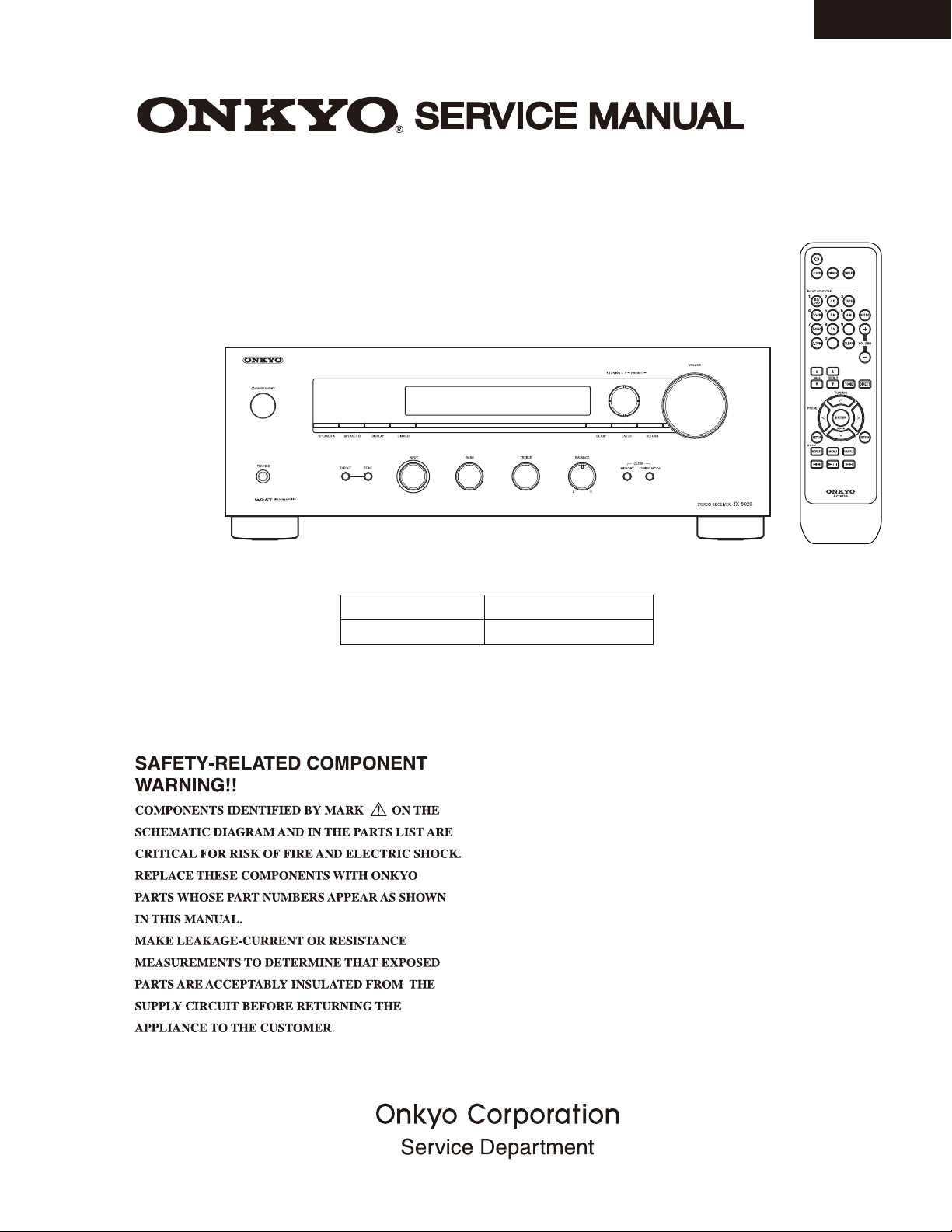
STEREO RECEIVER
MODEL TX-8020(B)/(S)
TX-8020
Ref. No. 4449
082013
Black and Silver models
B MDC
B MPP, S MPP
120V AC, 60Hz
230V AC, 50Hz
Features
50 Watts/Channel @ 8 Ω (FTC) (For North American Model)
90 Watts/Channel @ 6 Ω (IEC) (For European Model)
WRAT (Wide Range Amplifier Technology)
Discrete Amplifier Output Stage Circuitry
Massive EI Transformer
High-Current, Low-Impedance Drive
Direct Mode
5 Analog Audio Inputs and 1 Output
3 Digital Audio Inputs (1 Optical, 2 Coaxial) (European Model only)
Phono Input for Turntable Connection
Independent Bass, Treble, and Balance Controls
Subwoofer Pre-Out
Speaker A/B Terminals
Remote Interactive (RI) Input for Integrated Control of Compatible
Onkyo Components
Headphone Jack
40 FM/AM Random Presets
Preset Station Naming (Up to 8 Characters)
RDS (PS/PTY/RT) (European Model only)
3-Mode Display Dimmer (Normal/Dim/Dimmer)
Sleep Timer (via Remote)
Battery-Free Memory Back-up
Full-Sized, Full-Function RI Remote Control
RC-875S

TX-8020
SERVICE PROCEDURE
PRECAUTIONS
1. Ground for the work-desk.
Place a conductive sheet such as a sheet of copper (with impedance lower than 10Mohm) on the work-desk and place the set on
the conductive sheet so that the chassis.
2. Grounding for the test equipments and tools.
Test equipments and toolings should be grounded in order that their ground level is the same the ground of the power source.
3. Grounding for the human body.
Be sure to put on a wrist-strap for grounding whose other end is grounded.
Be particularly careful when the workers wear synthetic fiber clothes, or air is dry.
4. Select a soldering iron that permits no leakage and have the tip of the iron well-grounded.
5. Do not check the laser diode terminals with the probe of a circuit tester or oscilloscope.
REPLACING THE FUSE
This symbol located near the fuses indicates that the
fuse used is fast operating type. For continued protection
against fire hazard, replace with same type fuse. For
fuse rating refer to the marking adjacent to the symbol.
Ce symbole indique que le fusible utlise est a rapide.
Pour une protection permanente, n'untiliser que fusibles
de meme type. Ce darnier est la qu le present symbol
est appse.
To initialize the unit
Refer to “Initial setting for shipping” on “OPERATION CHECK-2”.
To check version of each Firmware
Refer to “Version confirmation” on “OPERATION CHECK-1”.
This symbol located near the fuses indicates that the
fuse used is slow operating type. For continued protection against fire hazard, replace with same type fuse. For
fuse rating refer to the marking adjacent to the symbol.
Ce symbole indique que le fusible utlise est e lent. Pour
une protection permanente, n'untiliser que fusibles de
meme type. Ce darnier est la qu le present symbol est
appse.

OPERATION CHECK-1
1.VERSION CONFIRMATION
Press [Display] + [Standby]
The version of main micom is displayed at FL tube.
2.CONFIRMATIONS OF OPERATIONS
Protect operation check
2-1. Voltage protection
a. Set to 1-05 of the TEST MODE
Refer to “4.TEST MODE” in OPERATIO CHECK-2
b. The speaker relay become OFF immediately after "D.C. 1.5V inputs" to CD SELECTOR to check L and R.
The same as above when "D.C. -1.5V" inputs at each place.
TX-8020
NOTE 1: Limit time to apply voltage is 0.5-1.0 seconds each channel.
NOTE 2: Don't connect load nor short speaker terminals.
2-2.Current protection
a. The unit receives the remote control signal D22F D1(K114) +D22F D9, it goes into the test mode (1-05)
b. The relay shall be ON when 2 ohm load is connected to each channel under the conditions of
peak-to-zero 20V output for L,R channels and no load by using the INTEGRA ampifier series
designated circuit with 50Hz square wave.
c. The relay shall be OFF when 0.5 ohm load is connected to each channel under the conditions of
peak-to-zero 20V output for L,R channels and no load by using the the INTEGRA ampifier series
designated circuit with 50Hz square wave.
2-3.
CONFIRMATION OF REMOTE CONTROL OPERATION
a.
Confirm that the specified operations for each button are made.
b.
Connect a compatible with RI unit, and confirm its operations.(RCA pin cord must be connected simultaneous)
CONFIRMATION OF RDS (RADIO DATA SYSTEM) OPERATION (Applied to
2-4.
a.
Input 98MHz,30dBμ signal modurated with RDS data.
b.
When a PS information is received, the name of the station "RDS TEST" shall be displayed within 2 seconds
instead of the frequency.
CONFIRMATION OF HEAD PHONE OPERATION
2-5.
Insert headphones plug in headphones Jack and confirm that the speaker output disappearing and the headphones
a.
indicator of the display turn on. into the PHONES jack.
Confirm that the output of SW_OUT in conjunction with speaker output A does not appear.
b.
When protection operation does not occur at once, try several times.
MPP ty
pe )
CONFIRMATION OF OUTPUT SENSOR AND THERMAL SENSER
2-6.
a.
Make volume level 5 .and Push ENTER_KEY.+STANDBY_KEY then Display (temperature ,VOLH,TAP) to FL TUBE.
Confirm outside temperature ±20C is displayed immediately after energizing.
Note that the error margin is caused by the rise of the temperature of the heat sink when time passes.
Confirm that turn the volume, and a value of VOLH changes.
b.
*If there is input, VOLH changes.
2-7.
MISCELLANEOUS
a. Confirm all input and output terminals operate normally.
b. Confirm FL TUBE TEST MODE
Please confirm FL displaying by the FL test mode.
And confirm the destination setting.
c. Confirm Key Operation
Confirm that the operation of all buttons and knobs works properly by the use of KEY test mode.
Table
TX-8020 EU R
TX-8020 US
: MPP
: MDC
OPERATION CHECK-2
Key Test
Comfirmation of VOLUME MIN
PROTECT
AUTO STOP,TUNED,STEREO
Comfirmation of MONO Output
Comfirmation of Destination and
Lit all segment
Lit '123456789ABCDE'
Lit an odd number segment
Lit a even number segment
Version display
IDLING Test
FL TEST
AF function
HUM,NOISE,
MIN NOIZ
TONE GAIN
BASS MAX
BASS MIN
TREBLE MAX
TREBLE MIN
BALANCE MAX
BALANCE MIN
MUTING
3.INITIAL SETTING FOR SHIPPING
a. Initialization of memories.
Press ON/STANDBY button while pressing down TUNING MODE button
when the unit is POWER ON, then the FL displays
"CLEAR", and turn to STAND-BY. Remove power cord from power line.
b.
POSITION OF KNOBS
Confirm that BALANCE knob are center position.
4. TEST MODE
Details of TEST MODE / TEST MODE tables
1. To TEST MODE
Set the volume position to 1.
Press [Enter] + [Standby]
Display as [Test _-__]
2. Select the TEST MODE in the following operations.
BASS UP TEST MODE UP
BASS DOWN
TREBLE UP
TREBLE DOWN
TEST MODE DOWN
TEST MODE UP
TEST MODE DOWN
1-00 --> 2-00 ----> 3-00 ...
3-00 ---> 2-00 ----> 1-00 ...
1-01 -->1-02 ----> 1-03 ...
1-03 -->1-02 ----> 1-01 ...
TX-8020
3.To EXIT
Press [Standby]
Display as [Clear]
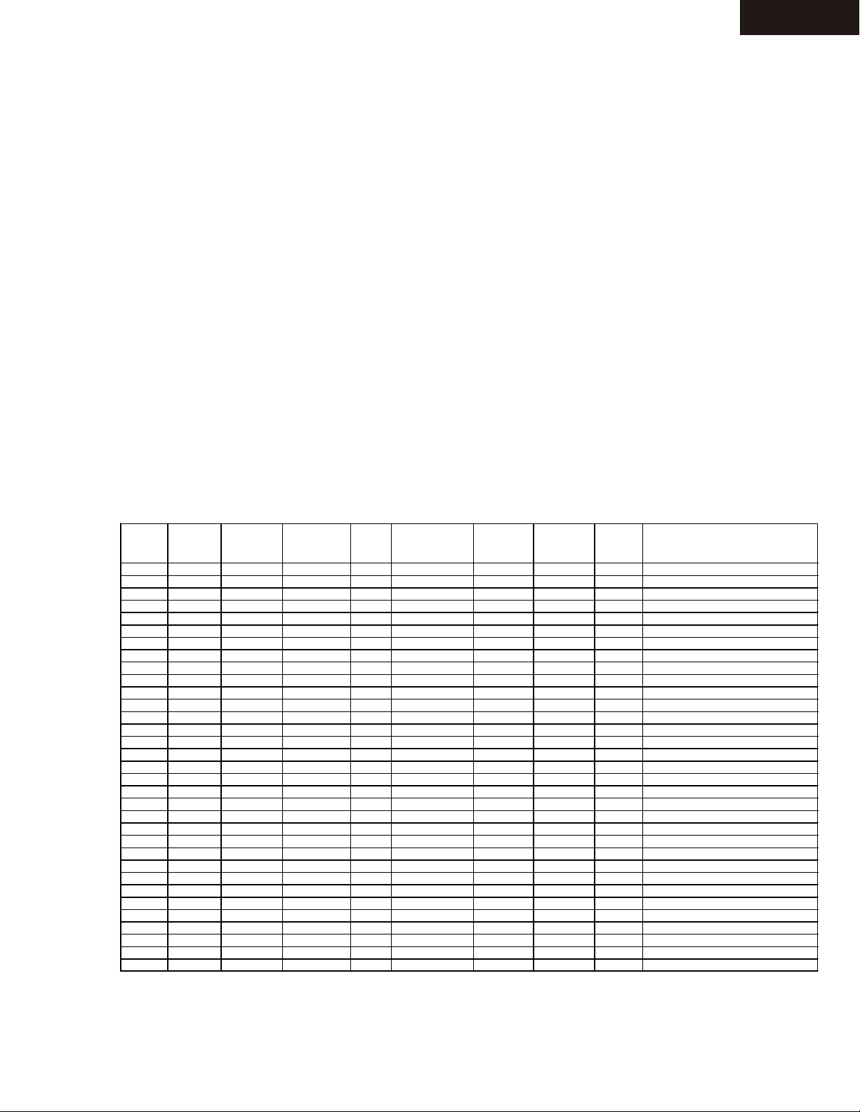
TEST INPUT Digital
No Input
1-00 CD ANALOG MIN 0 OFF AUTO OFF A
1-01 CD ANALOG MIN 0 OFF AUTO OFF A
1-02 CD ANALOG MIN 0 OFF AUTO OFF A
(0) CD ANALOG MIN 0 OFF AUTO OFF A
(1) CD ANALOG MIN 0 OFF AUTO OFF A
(2) CD ANALOG MIN 0 OFF AUTO OFF A
(3) CD ANALOG MIN 0 OFF AUTO OFF A
(4) CD ANALOG MIN 0 OFF AUTO OFF A
1-03 CD ANALOG MIN 0 OFF AUTO OFF A
1-04 CD ANALOG MIN 0 OFF AUTO OFF A
1-05 CD ANALOG MAX 0 Direct AUTO OFF A
2-00 CD ANALOG 70 0 Direct AUTO OFF B
2-01 CD ANALOG Max 0 Direct AUTO OFF AB
2-02 CD ANALOG Min 0 Direct AUTO OFF OFF
2-03 CD ANALOG 70 0 OFF AUTO OFF A
2-04 CD ANALOG 70 0 BASS MAX AUTO OFF A
2-05 CD ANALOG 70 0 BASS MIN AUTO OFF A
2-06 CD ANALOG 70 0 TREBLE MAX AUTO OFF A
2-07 CD ANALOG 70 0 TREBLE MIN AUTO OFF A
2-08 CD ANALOG 70 R-Max OFF AUTO OFF A
2-09 CD ANALOG 70 L-Max OFF AUTO OFF A
2-10 CD ANALOG 70 0 Direct AUTO ON A
3-0 PHONO ANALOG 34 0 Direct AUTO OFF A
3-1 PHONO ANALOG 20 0 Direct AUTO OFF A
3-2 PHONO ANALOG Max 0 Direct AUTO OFF A
3-3 CD OPT 70 0 Direct AUTO OFF A
3-4 CD COAX1 Max 0 Direct AUTO OFF A
3-5 FM ANALOG Min 0 Direct AUTO OFF A
('3-5) AM ANALOG Min 0 Direct AUTO OFF A Comfirmation of TUNED, Output
3-6 FM ANALOG Min 0 Direct OFF OFF A
3-7 AM ANALOG Min 0 Direct AUTO OFF A Comfirmation of TU
Master Vol. Balance Direct
Tuner Mode Muting Speaker
NED, Output
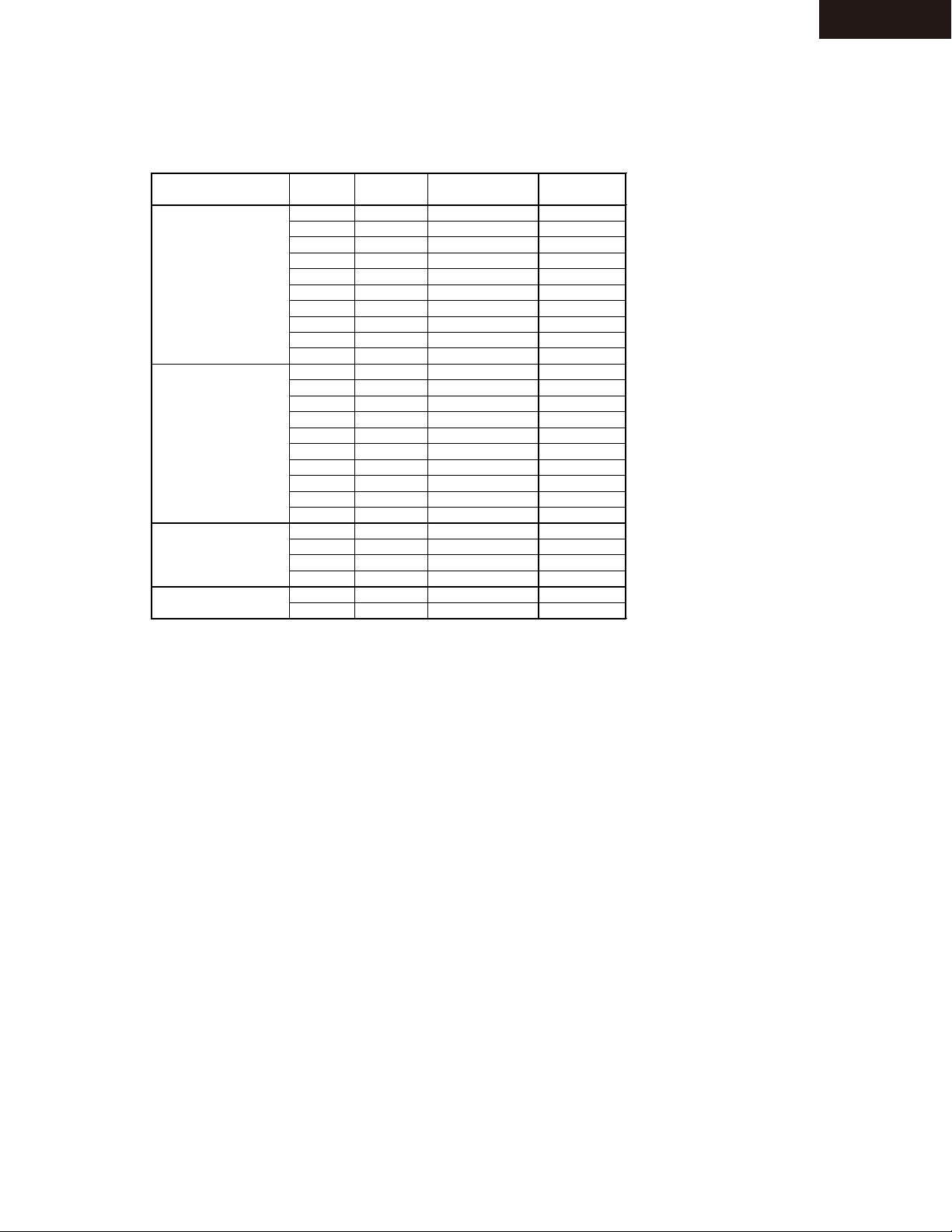
OPERATION CHECK-3
PRESET
No.
4. TEST MODE
Following frequencies are automatically written in the preset memory, when the unit goes into test mode.
TX-8020
1
2
3
4
FM 5
6
7
8
9
10
1
2
3
4
AM 5
6
7
8
9
10
11
FM 12
13
14
AM 11
12
MD* MP*,MG*
89.9MHz 89.90MHz 89.90MHz
97.9MHz 97.90MHz 97.90MHz
98.9MHz 98.90MHz 98.90MHz
107.1MHz 107.10MHz 107.10MHz
107.9MHz 107.90MHz 107.90MHz
100.1MHz 100.10MHz 100.10MHz
88.1MHz 88.10MHz 88.10MHz
104.1MHz 104.10MHz 104.10MHz
95.3MHz 95.30MHz 95.30MHz
106.7MHz 106.70MHz 106.70MHz
530KHz 530KHz 522KHz
630KHz 630KHz 630KHz
990KHz 990KHz 990KHz
1440KHz 1440KHz 1440KHz
1710KHz 1710KHz 1611KHz
670KHz 670KHz 666KHz
830KHz 830KHz 828KHz
1310KHz 1310KHz 1314KHz
1200KHz 1200KHz 1197KHz
530KHz 530KHz 522KHz
87.5MHz 87.50MHz 87.50MHz
107.9MHz 108.00MHz 108.00MHz
103.7MHz 104.00MHz 104.00MHz
104.5MHz 104.20MHz 104.20MHz
1180kHz 1180kHz 1179kHz
1220kHz 1220kHz 1215kHz
MW*(10k)
MW*(9k)
Special operation method
Method of temperature and VOLH
a.Set the volume position to 5.
b.Press [Enter] + [Standby]
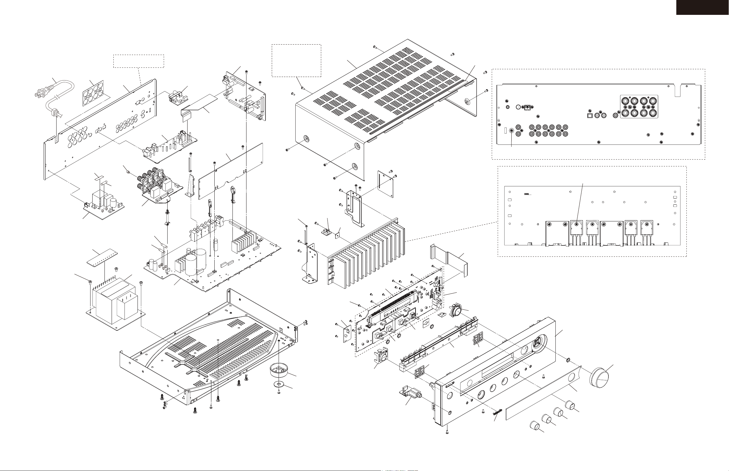
EXPLODED VIEWS-1
OVERALL
Refer to `Fig-1`
P901
A102
A101
U0050
U0040
P403
U0035
Black Model
3TTB+8B(3BC)
x 9 pcs.
Silver Model
3TTB+8B(3CM)SR
x 9 pcs.
TX-8020
<NOTE>
Please use the 3TTB+8B(BC) is screwed to the place that is not specified.
A340
A401
Fig-1
Rear Panel
F901E
U0036
U0011
SCREW
4TTC+8C(3BC)SR
x 4 pcs.
A421
x 8 pcs.
F901
U0034
T901
F6402
F6401
U0010
U0020
SCREW
3TTB+8B(3CM)SR
U0012
U0013
SCREW
2.6TTB+8B(3BC)
x 19 pcs.
U0031
DIS-1435
P701
U0030
A220
SCREW
3TTB+8B(3CM)SR
SCREW
3SMS6W.SW+14B(CU)
x 4 pcs.
Heatsink
Q6053
<NONE>
U0030 =
+ INPUT/BASS BOARD AS(BAETC-1446)
+
DISPLAY BOARD AS(BADIS-1435)
TREBLE BALANCE BOARD AS
BADIS-1435, BAETC-1442 and BAETC-1446 are connected by a jumper lead.
(BAETC-1442)
Q6050
Q6060Q6063
A003
x 4 pcs.
A004
x 4 pcs.
A213
ETC-1446
U0014
ETC-1442
A214
A203
A214
A204
A201
A321
A202
A211
A212
A212
A212
TX-8020
EXPLODED VIEWS-2
EXPLODED VIEW PARTS LIST
(B)MDC : 120V, Canadian/USA/(Mexico) model, Black
REF. NO. PART NAME DESCRIPTION Q'TY PART NO. (SN) REMARKS REF. NO. PART NAME DESCRIPTION Q'TY PART NO. (SN) REMARKS
[SEMI CONDUCTOR]
Q6050 TR 2SC5198-O 1 2203063
Q6050 or TR 2SC5198-R ( 1) 2203062
Q6053 TR 2SC5198-O 1 2203063
Q6053 or TR 2SC5198-R ( 1) 2203062
Q6060 TR 2SA1941-O 1 2203053
Q6060 or TR 2SA1941-R ( 1) 2203052
Q6063 TR 2SA1941-O 1 2203053
Q6063 or TR 2SA1941-R ( 1) 2203052
[CHASSIS SCREW]
A003 BOTTOM LEG phi48(313) 4 27175472
A004 CUSHION (ZUL) phi20 x phi8 4 28141900
A101 REAR PANEL MDC 1 27124533B
A102 LABEL (SP)2ch 1 29392373
[CABINET]
A201 F PANEL TX-8020(B)MDC 1 27213682
A202 CLEAR PLT TX-8020(B) 1 28192418
A203 KNOB (INP)B 1 28327158
A204 BADGE 1 28135317
A211 KNOB (TONE)(B)(8030) 1 28326952
A212 KNOB (INPUT)(B)(8030) 3 28326954
A213 KNOB (STBY)(B) 1 28326904
A214 KNOB (ZONE)(B)2pcs 2 28326945
A220 KNOB (CUR) 1 28326907B
A321 KNOB (VOL)AS(B) 1 28326914
A340 COVER (B) (Bent) 1 28210089A
A340 COVER (B) (Not Bent) 1 28210089AZ
A401 LABEL (COVER) 1 29390767
A402 LABEL HOOKUP-ONKYO 1 29363194
[TRANS COIL]
T901 P TRANS NPT-1618D 1 2302045
[SW TRM]
F6401 FUSE 10A-UL/T-233 1 252330GR
F6401 or FUSE 10A-T/UL-ST2 ( 1) 252333GR
F6402 FUSE 10A-UL/T-233 1 252330GR
F6402 or FUSE 10A-T/UL-ST2 ( 1) 252333GR
F901 FUSE 4A-UL/T-233 1 252325GR
F901 or FUSE 4A-T/UL-ST2 ( 1) 252257GR
P701 FFC NCFC7-332012 1 2047332012
P901 AC CORD AS-UC-2 1 253368AYUN
P901 or AC CORD AS-UC-2 ( 1) 253368BLTK
[TUNER UNIT]
U0010 AMP(ASP) PC BOARD AS BAAF-1472-1A 1 1B2935472-1A
U0011 TERMINAL(TRANS) PC BOARD AS BAETC-1475-1A 1 1B2935475-1A
U0012 THERMAL SENSOR PC BOARD AS BAETC-1477-1A 1 1B2935477-1A
U0013 FIX(SENSOR) PC BOARD AS BAETC-1478-1A 1 1B2935478-1A
U0014 PHONE JACK PC BOARD AS BAETC-1440-1A 1 1B2935440-1A
U0020 AMP(CLASS A) PC BOARD AS BACLA-1318-2A 1 1B2935318-2A
U0030 DISPLAY PC BOARD AS BADIS-1435-1A 1 1B2935435-1A
<NOTE>U0030 = DISPLAY BOARD AS(BADIS-1435)
+ INPUT/BASS BOARD AS(BAETC-1446)
+ TREBLE BALANCE BOARD AS(BAETC-1442)
BADIS-1435, BAETC-1442 and BAETC-1446 are connected by a jumper lead.
U0031 SWITCH(STANDBY) PC BOARD AS BADIS-1436-1A 1 1B2935436-1A
U0034 TERMINAL(SPEAKER) PC BOARD AS BATRM-1473-1A 1 1B2935473-1A
U0035 MPU PC BOARD AS BADG-1474-1A 1 1B2935474-1A
U0036 POWER SUPPLY PC BOARD AS BAPS-1476-1A 1 1B2935476-1A
U0040 TUNER PC BOARD AS BARF-1450-1A 1 1B2935450-1A
N
N
N
N
N
!
!
!
!
!
!
!
!
!
<Note>
Parts marked by "NSP" are generally unavailable because
they are not in our Master Spare Parts List.
(B)MPP : 230V, CE(European) country model, Black
[SEMI CONDUCTOR]
Q6050 TR 2SC5198-O 1 2203063
Q6050 or TR 2SC5198-R ( 1) 2203062
Q6053 TR 2SC5198-O 1 2203063
Q6053 or TR 2SC5198-R ( 1) 2203062
Q6060 TR 2SA1941-O 1 2203053
Q6060 or TR 2SA1941-R ( 1) 2203052
Q6063 TR 2SA1941-O 1 2203053
Q6063 or TR 2SA1941-R ( 1) 2203052
[CHASSIS SCREW]
A003 BOTTOM LEG phi48(313) 4 27175472
A004 CUSHION (ZUL) phi20 x phi8 4 28141900
A101 REAR PANEL MPP 1 27124534B
A102 LABEL (SP)2ch 1 29392373
[CABINET]
A201 F PANEL TX-8020(B)MDC 1 27213682
A202 CLEAR PLT TX-8020(B) 1 28192418
A203 KNOB (INP)B 1 28327158
A204 BADGE 1 28135317
A211 KNOB (TONE)(B)(8030) 1 28326952
A212 KNOB (INPUT)(B)(8030) 3 28326954
A213 KNOB (STBY)(B) 1 28326904
A214 KNOB (ZONE)(B)2pcs 2 28326945
A220 KNOB (CUR) 1 28326907B
A321 KNOB (VOL)AS(B) 1 28326914
A340 COVER (B) (Bent) 1 28210089A
A401 LABEL (COVER) 1 29390767
A421 P RIVET JB-407A-C 8 880052
[TRANS COIL]
T901 P TRANS NPT-1618P 1 2302046
[SW TRM]
F6401 FUSE 10A-UL/T-233 1 252330GR
F6401 or FUSE 10A-T/UL-ST2 ( 1) 252333GR
F6402 FUSE 10A-UL/T-233 1 252330GR
F6402 or FUSE 10A-T/UL-ST2 ( 1) 252333GR
F901 FUSE 2A-SE-EAK FUSE 1 252074GR
F901 or FUSE 2A-SE-TL250V ( 1) 252274GR
F901E FUSE LABEL T2AL250V 1 29363126
P403 FFC NCFC7-231212 1 2047231212
P701 FFC NCFC7-332012 1 2047332012
P901 AC CORD AS-CEE-2 1 253306VOL
P901 or AC CORD AS-CEE-2 ( 1) 253374YUN
[TUNER UNIT]
U0010 AMP(ASP) PC BOARD AS BAAF-1472-1B 1 1B2935472-1B
U0011 TERMINAL(TRANS) PC BOARD AS BAETC-1475-1B 1 1B2935475-1B
U0012 THERMAL SENSOR PC BOARD AS BAETC-1477-1B 1 1B2935477-1B
U0013 FIX(SENSOR) PC BOARD AS BAETC-1478-1B 1 1B2935478-1B
U0014 PHONE JACK PC BOARD AS BAETC-1440-1B 1 1B2935440-1B
U0020 AMP(CLASS A) PC BOARD AS BACLA-1318-2B 1 1B2935318-2B
U0030 DISPLAY PC BOARD AS BADIS-1435-1B 1 1B2935435-1B
<NOTE>U0030 = DISPLAY BOARD AS(BADIS-1435)
+ INPUT/BASS BOARD AS(BAETC-1446)
+ TREBLE BALANCE BOARD AS(BAETC-1442)
BADIS-1435, BAETC-1442 and BAETC-1446 are connected by a jumper lead.
U0031 SWITCH(STANDBY) PC BOARD AS BADIS-1436-1B 1 1B2935436-1B
U0034 TERMINAL(SPEAKER) PC BOARD AS BATRM-1473-1B 1 1B2935473-1B
U0035 MPU PC BOARD AS BADG-1474-1B 1 1B2935474-1B
U0036 POWER SUPPLY PC BOARD AS BAPS-1476-1B 1 1B2935476-1B
U0040 TUNER PC BOARD AS BARF-1450-1B 1 1B2935450-1B
U0050 DIGITAL PC BOARD AS BADG-1269-2B 1 1B2935269-2B
NOTE : THE COMPONENTS IDENTIFIED BY THE MARK
! ARE CRITICAL FOR RISK OF FIRE AND
ELECTRIC SHOCK. REPLACE ONLY WITH PART
NUMBER SPECIFIED.
N
N
N
N
N
!
!
!
!
!
!
!
!
!
!
 Loading...