

Page 1
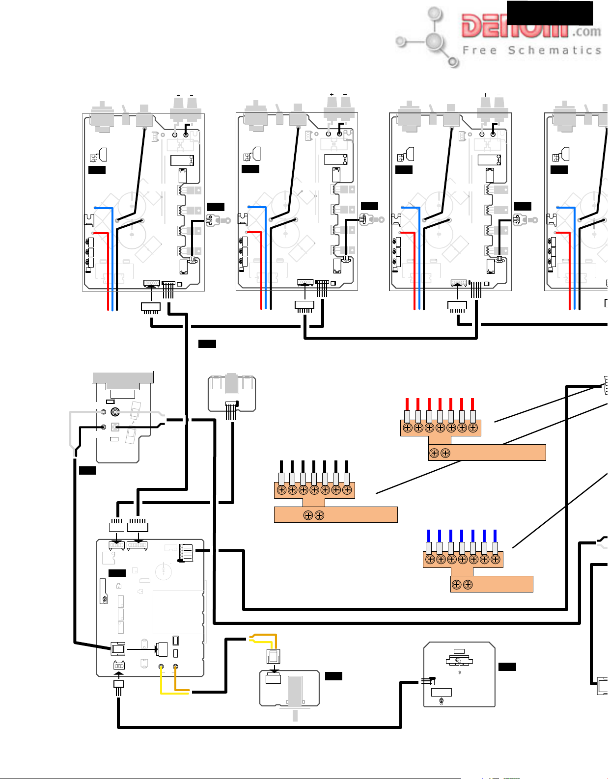
PC BOARD CONNECTION DIAGRAM
DTA-9.4
SURROUND BACK LEFT
XLR
INPUT
RCA
SELECT
P301
S301
P302
R430
P608B
OFFSET
U15
NAAF-7797
POWER AMPLIFIR PC BOARD
P601C
-B
BLUE
E601
P601A
P9911B
P9911A
U3
RED
DC
MODULATOR
OR
TEMPERATURE
P704
+B
OUTPUT
OPERATION
WARNING
CURRENT
P601B
P607A
INDICATOR
P702
GNDC
E
-B
+B
To NAPS-7789
AC INLET
P995
NL
AC-G
P997A
WHT
WHT
BLK
AC-H
BLK
F901
P996A
NAETC-7801
AC INLET PC BOARD
P608A
+5VC
OUTPUT
P607B
P501
WHITE
RL701
RL501
Q512
P502
BLACK
E501
HEAT SINK
P303
U16
R710
P703
JL701A
JL701B
NAAF-7798
U6
NAPS-7792
Q506 Q505 Q511
RL502
GMUTE
PHTCP
OUTRL
FMUTE
ERR
P701
SURROUND LEFT
XLR
INPUT
RCA
SELECT
P301
S301
P302
R430
P608B
OFFSET
U15
NAAF-7797
POWER AMPLIFIR PC BOARD
P601C
-B
BLUE
E601
+B
RED
P601A
DC
OUTPUT
OPERATION
MODULATOR
WARNING
INDICATOR
OR
CURRENT
TEMPERATURE
P704
P607A
+B
P601B
P702
GNDC
E
-B
P608A
+5VC
OUTPUT
P607B
P501
WHITE
RL701
RL501
Q512
P502
BLACK
E501
P303
U16
R710
JL701A
JL701B
NAAF-7798
Q506 Q505 Q511
RL502
P701
GMUTE
PHTCP
OUTRL
FMUTE
ERR
P703
XLR
P302
R430
OFFSET
U15
NAAF-7797
POWER AMPLIFIR PC BOARD
HEAT SINK
P601C
-B
BLUE
E601
+B
P601A
RED
DC
OUTPUT
OPERATION
MODULATOR
WARNING
INDICATOR
OR
CURRENT
TEMPERATURE
P704
P607A
+B
INPUT
SELECT
-B
S301
P601B
LEFT
P301
P608B
P702
RCA
GNDC
P303
P608A
ERR
+5VC
OUTPUT
P607B
P501
P502
WHITE
BLACK
E501
RL701
RL501
Q512
U16
R710
JL701B
Q506 Q505 Q511
JL701A
RL502
GMUTE
PHTCP
OUTRL
FMUTE
P701
P703
U15
NAAF-7797
HEAT SINK
P601C
BLUE
E601
RED
P601A
DC
MODULATOR
OR
TEMPERATURE
NAAF-7798
P704
E
CENTER
XLR
INPUT
RCA
SELECT
P301
S301
OFFSET
+B
P607A
P608B
P601B
P702
E
-B
P302
R430
POWER AMPLIFIR PC BOARD
-B
+B
OUTPUT
OPERATION
WARNING
INDICATOR
CURRENT
12V TRIGGER TERMINAL PC BOARD
12V TRIGGER IN
E9902
P9908A
P9910
E9903
To NAAF-7797
SURR BACK LEFT
SURR LEFT
LEFT
CENTER
RIGHT
SURR RIGHT
SURR BACK RIGHT
E
SURR BACK LEFT
SURR LEFT
LEFT
CENTER
RIGHT
To NAAF-7797
SURR RIGHT
SURR BACK RIGHT
+B
P9909
P9908B
U7
NAPS-7793
WARNING
POWERSUPPLY
CONTROL PC BOARD
D9805
F9801
P9907B
P9911C
YEL
T9801
AC-G
AC-H
P9904
JL9906A
BRN
U9
P9904A
NASW-7795
S9801
POWER
www.denom.com
POWER SWITCH
PC BOARD
SURR BACK LEFT
SURR LEFT
LEFT
CENTER
RIGHT
To NAAF-7797
POWER
D9812
A
P9907A
K
STAND-BY
WARNING
D9813
SURR RIGHT
SURR BACK RIGHT
-B
U8
NAETC-7794
DISPLAY LED
PC BOARD
Page 2
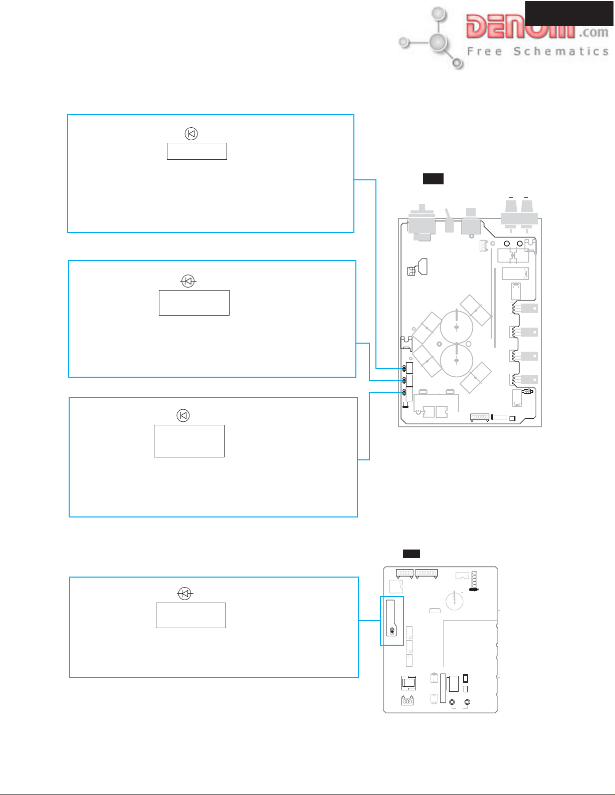
OPERATION CHECK-4
OPERATION INDICATOR IN THE UNIT-1
DTA-9.4
(RED)
D705
DC OUTPUT
D705 (DC OUTPUT)
This LEDTurned on when DC voltage is detected between speaker output
terminals.
Spealer output relay is turned off while having detected DC voltage.
The relay will return automatically, if DC voltage output is lost.
(ORANGE)
D710
MODULATOR
OPERATION
D710 (MODULATOR)
This LED shows the state of operation of an modulation circuit.
Immediately after a power supply injection, the light is switched on, and
this LED will put out the light, if operation of modulation circuit is started.
(RED)
D751
TEMPERATURE
OR
CURRENT
P601C
BLUE
E601
P601A
-B
+B
RED
DC
OUTPUT
OPERATION
MODULATOR
OR
CURRENT
TEMPERATURE
P704
XLR
R430
WARNING
INDICATOR
U15
SELECT
OFFSET
P607A
NAAF-7797
INPUT
RCA
P601B
P702
OUTPUT
E501
RL701
RL501
Q512
L505
Q506 Q505 Q511
JL701A
RL502
P701
P703
D751 (TEMPERATURE OR CURRENT)
This LED is turned on when an unusual temperature rise and unusual
over-current of an amplifier circuit are detected.
(RED)
D9805
POWER SUPPLY
WARNING
D9805(POWER SUPPLY WARNING)
This LED is turned on when abnormalities arise in the
power supply circuit.
SUPPLY
WARNING
POWER
D9805
U7
P9908B
NAPS-7793
P9909
Q9803
Q9827
Q9806
F9801
P9907B
1A/125V
P9911C
YEL
AC-H AC-G
P9904
JL9906A
T9801
BRN
www.denom.com
Page 3
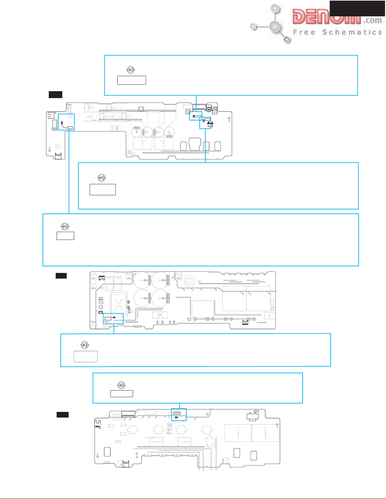
OPERATION CHECK-5
OPERATION INDICATOR IN THE UNIT-2
DTA-9.4
U2
GND2
+12V
PROT
+12V
RLRL+
JL9906B
P903B
(RED)
NAPS-7789
P161
PROT
TEST
E102
Q103
D161
PROT
RL+
RL-
GND2
D161
PROT
(RED)
REGULATED
This LED is turned on when the voltage of a secondary power supply output is normal.
D133
The detection circuit which is source of the drive about this LED is supervising only
the voltage difference between the positive power supply of secondary voltage, and the
negative power supply.
D133 (REGULATED)
E122 E121
E126 E125
(RED)
LOW
CURRENT
E124 E123
E101
D136
+B
E114
E
-B
E113
E174
E175
P101A
L102
E192
TH1
TH2+
TH2-
E112
E173
L101
E191
D136 (LOW CURRENT)
This LED is turned on when a low load measure circuit operates.
When the switching power supply of this unit has very little load to a power supply,
the voltage of a secondary side output rises rapidly.
In such a case, a problem is avoided by lowering voltage.
VOLTAGE
ADJUST
+B
+B
GND2
CTRL1
CTRL2
P131A
R139
REGULATED
D133
LOW
CURRENT
D136
D923
D920D921 D922
+B
-B
GND
VOLTAGE
CHECK
P108
JL132B
This circuit may operate temporarily at the time of a power supply ON.
D161 (PROT)
This LED is turned on when the protection circuit of a power supply operates.
The protection circuit of a power supply section consists of following detection circuits.
1. Over voltage detection of a secondary DC output.
2. Thermal detection of primary power supply circuit.
3. Thermal detection of secondary power supply circuit.
This LED may be turned on only for a moment. It is because the state of a protection circuit is not held in NAPS-7789.
U1
NAPS-7788
(RED)
PRI DC
LIVE
U5
NAPS-7790
PRI
E906
L103
P101B
GND
SEC
E984
L906
UDD UJJ
UJJ
UDD
E986
UDD
D102 D101D104 D103
E990
T901
UJJ
P902A
E991
E988
E987
T902
E985B
E985A
UDD
UJJ
VC+
VC-
VC-
E904
E902
E901
SEC
P997B
RL-
BLK
AC-H
P996B
AC-G
WHT
P903A
RL+
GND2
PRI
RL902
PRIDC
E905
RL902
RL901
BLK
P801A
AC-H2
E982
P801B
AC-G2
WHT
D907
LIVE
E981
E903
E983
D902
D907 (PRI DC LIVE)
D907
This LED is turned on when the electric charge remains in the primary side capacitor.
Do after discharging by resistance and checking putting out lights of this LED, when
disassembling a unit.
D851 (TH1 PROT)
This LED lights up at the time of the usual operation.
The light is put out when the thermal protection circuit of
a primary power supply section operates.
P803A
SEC
TH1
GND2
TH2-
TH2+
CTRL1+BCTRL2
+B
T854
E895
R861
Q884
R848
TH1 PROT
Q851
D851
E806
JL805B
Q882
T852
Q881
T853
Q883
R181
T851
E892
E893
E894
PRI
E891
E881
AC-H2 AC-G2
P801C
P801C
E841
(RED)
TH1 PRO
Q813
Q842
D851
Q801
Q817
Q812
Q814
P902B
E989
FORTEST
12V INPUT
+-
P904
www.denom.com
Page 4
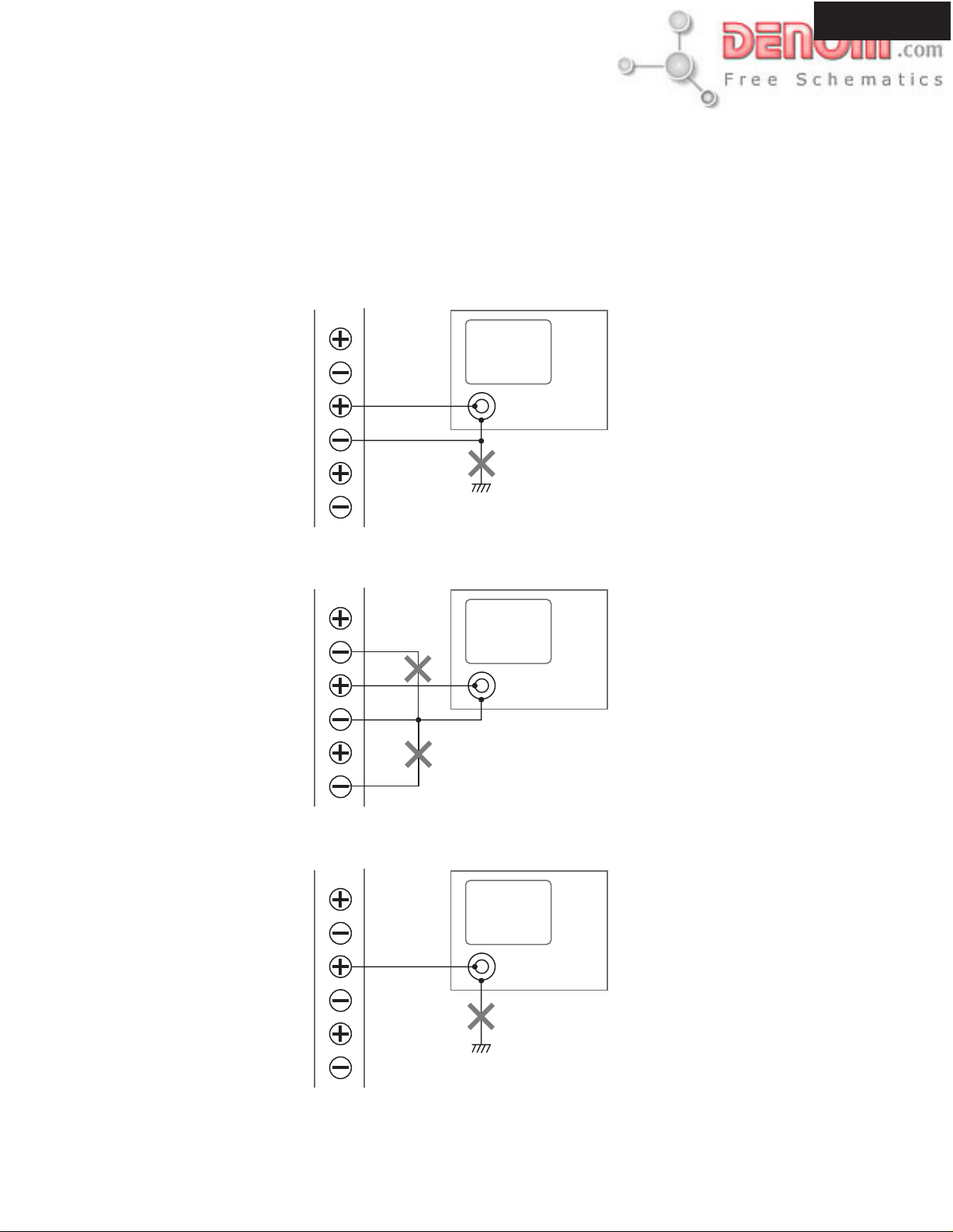
OPERATION CHECK-6
CAUTION IN THE CASE OF SPEAKER OUTPUT CHECK
The power amplifier circuit of DTA-9.4 is BTL system.
Therefore, in case you check speaker output, should be careful of the following point.
1. Do not connect the minus side OUTPUT terminal, and ground of the unit (Fig-1).
2. Do not connect minus of each OUTPUT terminal. (Fig-2).
3. Cannot check with an oscilloscope between the plus side of an OUTPUT terminal, and Chassis GND. (Fig-3).
Fig-1
OUTPUT
LEFT
CENTER
Oscilloscope
DTA-9.4
RIGHT
Fig-2
LEFT
CENTER
RIGHT
Fig-3
LEFT
Chassis GND of unit
OUTPUT
OUTPUT
CENTER
RIGHT
Chassis GND of unit
www.denom.com
Page 5

OPERATION CHECK-1
CURRENT DETECTION OF POWER SUPPLY
Notes
No load and No signal input.
How to check?
1. Connect the power supply card to a wall outlet.
2. Power On the unit.
3. Short-circuit the both ends of P161 on NAPS-7789.
4. Check that it is as follows.
GND2
+12V
PROT
+12V
RLRL+
JL9906B
P903B
DTA-9.4
P161
PROT
TEST
P161
PROT
TEST
E102
D161
PROT
RL+
RL-
GND2
Q103
U2
NAPS-7789
E122 E121
E126 E125
E124 E123
+B
E114
E
-B
E174
E175
E101
P101A
L102
E113
E192
TH2+
TH2-
E112
E173
L101
E191
+B
+B
TH1
GND2
CTRL1
CTRL2
P131A
REGULATED
D133
D136
D923
D920D921 D922
VOLTAGE
+B
-B
GND
ADJUST
VOLTAGE
CHECK
R139
P108
LOW
CURRENT
JL132B
Standby
Power
Lights
Blinks
RELAYS AND INDICATORS
How to check?
2. Connect the power supply card to a wall outlet.
4. Power On the unit.
5. Immediately after power switch On.
Check
Blinks
Power
Standby
4. About 1 second after turning On a power supply.
Check
RL501 and RL502 Relays ON.
5. About 10 seconds after turning On a power supply.
Check
RL701 Relays ON.
Check
Lights
XLR
INPUT
SELECT
P302
R430
OFFSET
U15
NAAF-7797
P601C
-B
BLUE
E601
P607A
+B
RED
P601A
DC
OUTPUT
OPERATION
MODULATOR
WARNING
INDICATOR
Q604
OR
CURRENT
TEMPERATURE
Q711
P704
Q717
RCA
P301
S301
P608B
P601B
P608A
Q603
P702
GNDC
OUTPUT
P607B
P501
P502
WHITE
P303
P504
L505
GMUTE
PHTCP
OUTRL
FMUTE
ERR
+5VC
BLACK
E501
RL701
RL501
Q512
P503
Q506 Q505 Q511
JL701A
RL502
P701
P703
RL701
RL501
RL502
Standby
Power
Blinks stop
www.denom.com
Page 6

OPERATION CHECK-2
DC VOLTAGE DETECTION OF POWER AMPLIFIER CIRCUIT
Notes
No load and No signal input.
How to check?
1. Connect the power supply card to a wall outlet.
2. Power On the unit.
3. Set the INPUT SELECT switch of a rear panel to the RCA side.
4. Apply DC+3V to a RCA terminal.
5. Check that the speaker relay RL701 is turned off.
6. Apply DC+3V to a RCA terminal.
7. Check that the speaker relay RL701 is turned off.
Rear panel
DTA-9.4
DC+3V or -3V
OVER CURRENT DETECTION OF POWER AMPLIFIER CIRCUIT
Notes
1. Check only one channel at a time.
2. Interrupt a input signal, immediately after a speaker relay goes out.
3. Don't change into the state where load was connected to amplifier, more than for 3 seconds.
How to check?
1. Set the output of the oscillator into the minimum level.
2. Connect the oscilloscope to the OUTPUT terminal.
3. Output a 200Hz rectangular wave from an oscillator, and input into a RCA terminal through the appointed differentiation circuit.
4. Turn on the unit.
5. Adjust the output level of oscillator so that the level of the waveform of the OUTPUT terminal become 35 Vp-p.
6. Connect 2-ohms load to the OUTPUT terminal.
7. Check that the speaker relay RL701 is not turned off .
8. Connect 0.3-ohm load to the OUTPUT terminal.
9. Check that the speaker relay RL701 is turned off immediately.
Differentiation
circuit.
200Hz
35Vp-p
Input
GND
3.3k
0.1 F
10k
1SS133
3.3k
Output
0.01 F
GND
www.denom.com
Page 7

OPERATION CHECK-3
THERMAL DETECTION OF POWER AMPLIFIER CIRCUIT
Notes
No load and No signal input.
How to check?
1. Connect the power supply card to a wall outlet.
2. Power On the unit.
3. Short-circuit the both ends of P703 on NAAF-7797.
4. Check that it is as follows.
U15
R430
OFFSET
NAAF-7797
POWER AMPLIFIER PC BOARD
DTA-9.4
Check
Light
D751
OR
TEMPERATURE
CURRENT
P601C
BLUE
E601
P601A
RED
DC
MODULATOR
TEMPERATURE
-B
P601B
P607A
+B
OUTPUT
OPERATION
WARNING
Q604
INDICATOR
OR
CURRENT
P704
Q603
Q711
Q717
P702
P703
P703
Short
www.denom.com
Page 8

DISASSEMBLING PROCEDURES-4
DISASSEMBLING OF POWER SUPPLY UNIT
Remove 18 soldering.
13
Front side
17
DTA-7
By doing the following work, You can separate NAPS-7789
and NAPS-7790.
1. Disconnect the terminal PCB assy NAPS-7791.
2. Remove the four screws.
NAPS-7791
Remove the four screws.
14
Remove the five screws.
15
By doing the following work, You can separate NAPS-7790
18
and the heat sink.
1. Remove two soldering.
2. Remove the six screws.
By doing the following work, You can separate NAPS-7789
19
and the heat sink.
1. Remove four soldering.
2. Remove the nine screws.
By disconnect the socket assy P801, You can remove
16
the PCB assy NAPS-7788.
www.denom.com
Page 9

DISASSEMBLING PROCEDURES-2
REMOVE A POWERB AMP. UNIT AND A POWER SUPPLY UNIT FROM CHASSIS
DTA-9.4
Remove the three screws.
1 4
Rear panel
Remove the four screws.
2
Front side
Move the power supply unit to front side.
Power supply unit
Front side
Take out a power amp. unit from the chassis.
5
Power amp. unit
Remove the eight screws.
3
Front side
www.denom.com
Page 10

DISASSEMBLING PROCEDURES-3
REMOVE A POWERB AMP. UNIT AND A POWER SUPPLY UNIT FROM CHASSIS
DTA-9.4
Remove the four screws.
7 11
Front side
Remove the four screws.
8
12
Move the power supply unit to up side.
Power supply unit
NAPS-7788
Soldering side
Power supply unit
9
Remove the two screws.
By removing each screw of three copper plates
10
(RETAINER), You can remove an amplifier unit
completely.
www.denom.com
Page 11

DTA-9.4
RCA
P301
P607B
P303
P608A
P702
GMUTE
PHTCP
OUTRL
FMUTE
ERR
+5VC
GNDC
GND2
+12V
PROT
+12V
RLRL+
JL9906B
E904
E902
SEC
E901
NAPS-7790
P701
WHITE
P501
Q512
Q506 Q505 Q511
E102
OUTPUT
P502
RL501
RL502
P703
D161
BLACK
RL701
JL701A
E501
P161
PROT
TEST
Q103
PROT
U16
R710
JL701B
NAAF-7798
XLR
P302
R430
U15
NAAF-7797
HEAT SINK
POWER AMPLIFIR PC BOARD
P601C
-B
BLUE
E601
+B
RED
P601A
DC
OUTPUT
OPERATION
MODULATOR
WARNING
INDICATOR
OR
CURRENT
TEMPERATURE
P704
E122 E121
E126 E125
INPUT
SELECT
OFFSET
P607A
E
-B
+B
E124 E123
U2
RL-
P903B
RL-
GND2
AC-H
P996B
P997B
AC-G
PRI
RL+
GND2
P903A
RL+
RL902
BLK
WHT
RL902
RL901
PRI DC
D907
LIVE
E981
E903
NAPS-7789
SECONDARY POWER SUPPLY
PC BOARD
E905
BLK
P801A
AC-H2
E982
P801B
AC-G2
WHT
E983
D902
U4
NAETC-7802
E881
E891
U5
SWITCHING CONTROL PC BOARD
P801C
PRI
AC-G2
AC-H2
RIGHT
RCA
P301
S301
P608B
P601B
P702
E892
P607B
P501
WHITE
P303
P608A
GMUTE
PHTCP
OUTRL
FMUTE
ERR
+5VC
GNDC
P701
+B
E
E175
E101
E113
TEMPERATRE
SENSOR
PC BOARD
PRI
JL805B
E894
E893
T851
R181
OUTPUT
P502
RL701
RL501
Q512
Q506 Q505 Q511
RL502
P703
E114
E906
U11
BLACK
E501
JL701A
-B
P101A
L102
E192
R184
L103
E984
UDD
R854
Q881
JL805B
T852
D851
SURROUND RIGHT
XLR
INPUT
SELECT
S301
P302
R430
OFFSET
U15
NAAF-7797
HEAT SINK
U16
R710
JL701B
NAAF-7798
E174
JL132A
P101B
GND
U1
NAPS-7788
PRIMARY POWER SUPPLY
PC BOARD
UDD UJJ
UJJ
NAETC-7802
Q882
E806
Q851
TH1 PROT
POWER AMPLIFIR PC BOARD
P601C
-B
BLUE
E601
P607A
+B
RED
P601A
DC
OUTPUT
OPERATION
MODULATOR
WARNING
INDICATOR
OR
CURRENT
TEMPERATURE
P704
E
-B
+B
+B
TH1
GND2
TH2+
TH2-
CTRL1
E112
E173
L101
E191
D920D921 D922
SEC
L906
E986
UDD
UJJ
TEMPERATRE
SENSOR
PC BOARD
R848
Q884
Q883
T853
TH2+
SEC
R861
E895
+B
CTRL1+BCTRL2
GND2
TH2-
TH1
P803A
P601B
+B
CTRL2
D133
E990
P902A
RCA
P301
P608B
P702
P131A
REGULATED
T901
T854
GNDC
D923
E988
UDD
P902B
P303
P608A
FMUTE
ERR
+5VC
D136
E985A
OUTRL
CURRENT
D102 D101D104 D103
PHTCP
GMUTE
VOLTAGE
ADJUST
R139
LOW
VC-
OUTPUT
P607B
P501
P502
WHITE
BLACK
E501
RL701
RL501
Q512
U16
R710
P703
JL701A
JL701B
NAAF-7798
P701
VOLTAGE
P108
Q506 Q505 Q511
RL502
+B
-B
GND
CHECK
SURROUND BACK RIGHT
XLR
INPUT
SELECT
S301
R430
P608B
OFFSET
P302
U15
NAAF-7797
HEAT SINK
POWER AMPLIFIR PC BOARD
P601C
-B
BLUE
E601
P601A
RED
DC
MODULATOR
TEMPERATURE
+B
OUTPUT
OPERATION
WARNING
OR
CURRENT
P704
INDICATOR
+B
P607A
P601B
E
-B
RCA
P301
P702
GNDC
P608A
+5VC
OUTPUT
P607B
P501
WHITE
RL701
RL501
Q512
P502
BLACK
E501
HEAT SINK
P303
U16
R710
JL701A
JL701B
NAAF-7798
Q506 Q505 Q511
RL502
P701
GMUTE
PHTCP
OUTRL
FMUTE
ERR
P703
JL132B
P131B
E991
E989
E987
U14
NAPS-7791
T902
FORTEST
12V INPUT
+-
P904
E985B
UJJ
VC+
VC-
P803B
Q842
E841
Q801
Q817
TERMINAL PC BOARD
[NOTES]
SOCKET ASSY
JUMPER WIRE
BORAD TO BOARD
www.denom.com
 Loading...