

Page 1
SERVICE MANUAL
SERVICE MANUAL
r
/
ON
BY
C
01
A
L
Compact Disc Playe
C-701A
Ref. No. 3696
092001
MODE
SMPP,SMGT
SMDT
SMGR
-701
7
Silver model
230-240V AC, 50Hz
120V AC, 60Hz
220-230V AC, 50/60Hz
SAFETY-RELATED COMPONENT
WARNING!!
COMPONENTS IDENTIFIED BY MARK ON THE
SCHEMATIC DIAGRAM AND IN THE PARTS LIST ARE
CRITICAL FOR RISK OF FIRE AND ELECTRIC SHOCK.
REPLACE THESE COMPONENTS WITH ONKYO
PARTS WHOSE PART NUMBERS APPEAR AS SHOWN
IN THIS MANUAL.
MAKE LEAKAGE-CURRENT OR RESISTANCE
MEASUREMENTS TO DETERMINE THAT EXPOSED
PARTS ARE ACCEPTABLY INSULATED FROM THE
SUPPLY CIRCUIT BEFORE RETURNING THE
APPLIANCE TO THE CUSTOMER.
Page 2
SERVICE PROCEDURES 1
PROTECTION OF EYES FROM LASER BEAM DURING SERVICING
C-701A
This set employs a laser. Therefore, be sure to follow
carefully the instructions below when servicing.
WARNING!!
SERVICE WARNING : DO NOT APPROACH THE
LASER EXIT WITH THE EYE TOO CLOSELY.
IN CASE IT IS NECESSARY TO CONFIRM LASER
BEAM EMISSION, BE SURE TO OBSERVE FROM
A DISTANCE OF MORE THAN 30cm FROM THE
SURFACE OF THE OBJECTIVE LENS ON THE
OPTICAL PICKUP BLOCK.
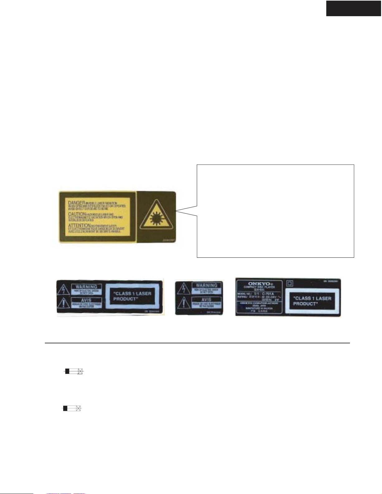
LASER WARNING LABEL
The labels shown below are affixed.
1. Warning label
Laser Diode Properties
Material: GaAS/GaAlAs
Wavelength: 780nm
Laser output: max. 0.5mW*
Emission Duration: continuous
*This output is the value measured at a distance about 1.8mm
from the objective lens surface on the Optical Pickup Block.
DANGER:
INVISIBLE LASER RADIATION WHEN OPEN AND
INTERLOCK FAILED OR DEFEATED. AVOID DIRECT
EXPOSURE TO BEAM.
CAUTION:
HAZARDOUS LASER AND ELECTROMAGNETIC
RADIATION WHEN OPEN AND INTERLOCK DEFEATED.
ATTENTION:
RAYONNEMENT LASER ET ELECTROMAGNETIQUE
DANGEREUX SI OUVERT AVEC L'ECLENCHEMENT
DE SECURITE ANNULE.
2. Class 1 label
MPP/MGT MDT MGR
1. Replacing the fuse
THIS SYMBOL LOCATED NEAR THE FUSE INDICATES
THAT THE FUSE USED IS SLOW OPERATING TYPE
FOR CONTINUED PROTECTION AGAINST FIRE
HAZARD,REPLACE WITH SAME TYPE FUSE. FOR FUSE
RATING REFER TO THE MARKING ADJACENT TO THE SYMBOL
CE SYMBOLE INDIQUE QUE LE FUSIBLE UTLISE EST
E LENT. POUR UNE PROTECTION PERMANENTE,N'UTILISER
QUE DES FUSIBLES DE MEME TYPE. CE DARNIER EST
INDIQUE LA QU LE PRESENT SYMBOL EST APPOSE.
REF. NO. PART NO. DESCRIPTION
F901 252074 2A-SE-EAK
<MPP,MGR,MGT>
2.Safety check out
(Only U.S.A. model)
After correcting the original service problem perform
the following safety check before releasing the set
to the customer.
Connect the insulating-resistance tester between the
plug of power supply cord and terminal GND on the
back panel.
Specifications: More than 10 M ohm at 500V.
Page 3
SERVICE PROCEDURES 2
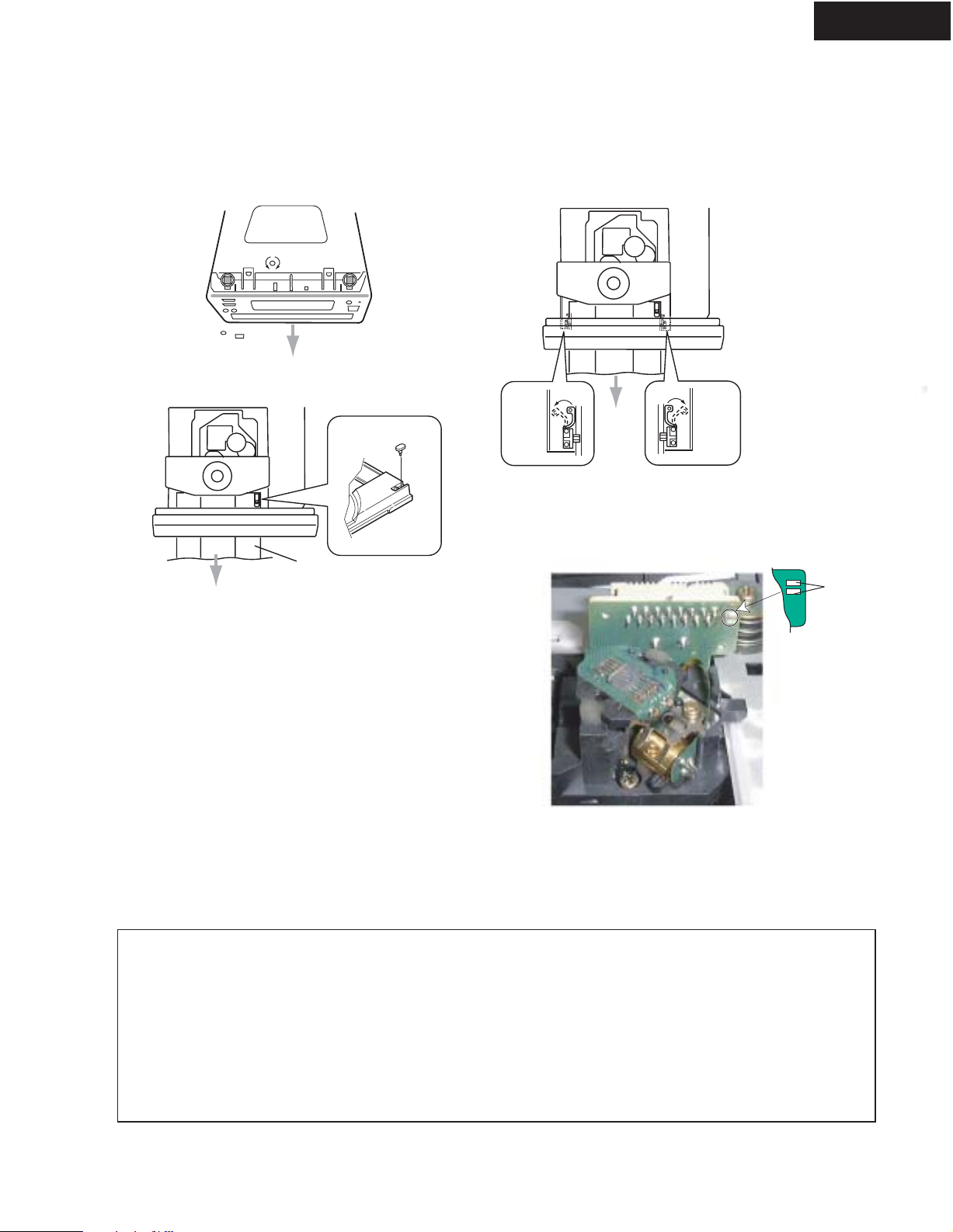
1. Removement of tray
1. Remove the top cover
2. Turn the locked screw to the clockwise to release the lock of gear.
(Refer to fig-1)
Fig-1
Bottom side
Lock
Unlock
C-701A
5. Press the tray stopper to the arrow mark direction and remove
the tray ass'y. (Refer to fig-3)
Fig-3
3. Pull out the tray.
4. Remove the stopper. (Refer to fig-2)
Front
Front
Fig-2
Stopper
Tray
2. Replacement of optical pick-up
The laser diode in the optical pickup block is so sensitive to static
electricity, surge current and etc. that the components are liable to
be broken down or its reliability remarkably deteriorated.
During repair, carefully take the following precautions.
1. Solder the LD short terminal on mechanism.
2. Disconnect the flexible flat cable P101.
3. Replace the optical pickup.
4. Connect the flexible flat cable P101.
5. Unsolder the LD short terminal on mechanism.
Tray
stopper
Front
Tray
stopper
LD Short
Terminal
NOTE
1. Ground for the work-desk.
Place a conductive sheet such as a sheet of copper
(with impedance lower than 10Mohm) on the work desk and place the set on the conductive sheet so that
the chassis can be grounded.
2. Grounding for the test equipments and tools.
Test equipments and toolings should be grounded in
order that their ground level is the same the ground of
the power source.
Pick up short land
3. Grounding for the human body.
Be sure to put on a wrist-strap for grounding whose
other end is grounded.
Be particularly careful when the workers wear
synthetic fiber clothes, or air is dry.
4. Select a soldering iron that permits no leakage and
have the tip of the iron well-grounded.
5. Do not check the laser diode terminals with the
probe of a circuit tester or oscilloscope.
Page 4

SPECIFICATIONS
C-701A
Signal readout system : Optical non-contact
Reading rotation : About 500 - 200 r.p.m.
(constant linear velocity)
Linear velocity : 1.2 - 1.4 m/s
Error correction system :
Cross Interleave Reed Solomon code
D/A converter : 1 bit D/A converter
Sampling frequency : 352.8 kHz
(Eight-times oversampling)
Number of channels : 2 (stereo)
Frequency response : 5 Hz - 20 kHz
Total harmonic distortion : 0.009% (at 1 kHz)
Dynamic range : 92 dB
Signal to noise ratio : 80 dB
Channel separation : 80 dB (at 1 kHz)
Specifications and external appearance are subject to
change without notice because of product improvements.
Wow and Flutter :
Below threshold of measurability
Output level : 2 volts r.m.s.
Power consumption :
AC 230-240 V, 50 Hz model : 8 watts
AC 220-230V, 50Hz/60Hz : 8 watts
AC 120 V, 60 Hz model : 9 watts
Power supply rating :
AC 230-240 V, 50 Hz
AC 220-230V, 50Hz/60Hz
AC 120 V, 60 Hz
Dimensions (W x H x D) :
155 x 76 x 283.5 mm <MGR> model
6-1/8" x 3" x 11-3/16"
155 x 76 x 281.5 mm <MPP/MGT> model
6-1/8" x 3" x 11-1/16"
155 x 76 x 277.5 mm <MDT> model
Weight : 2.0 kg, 4.4 lbs.
<MPP>: European model only
<MDT>: Taiwanese model only
<MGT>: Asian model only
<MGR>: Chinese model only
CONFIRM THE FL DISPLAY
1) Press the STANDBY key ON.
2) Press and hold down the STOP button, then
press the UP button.
After " 010702A" (Microprocessor version) is
displayed. All the segments of FL tube light up
after 1 seconds.
3) Press the STOP key . ("NO KEY" is displayed)
4) Confirm the each key.
5) Press the STANDBY key to release the test mode.
Page 5
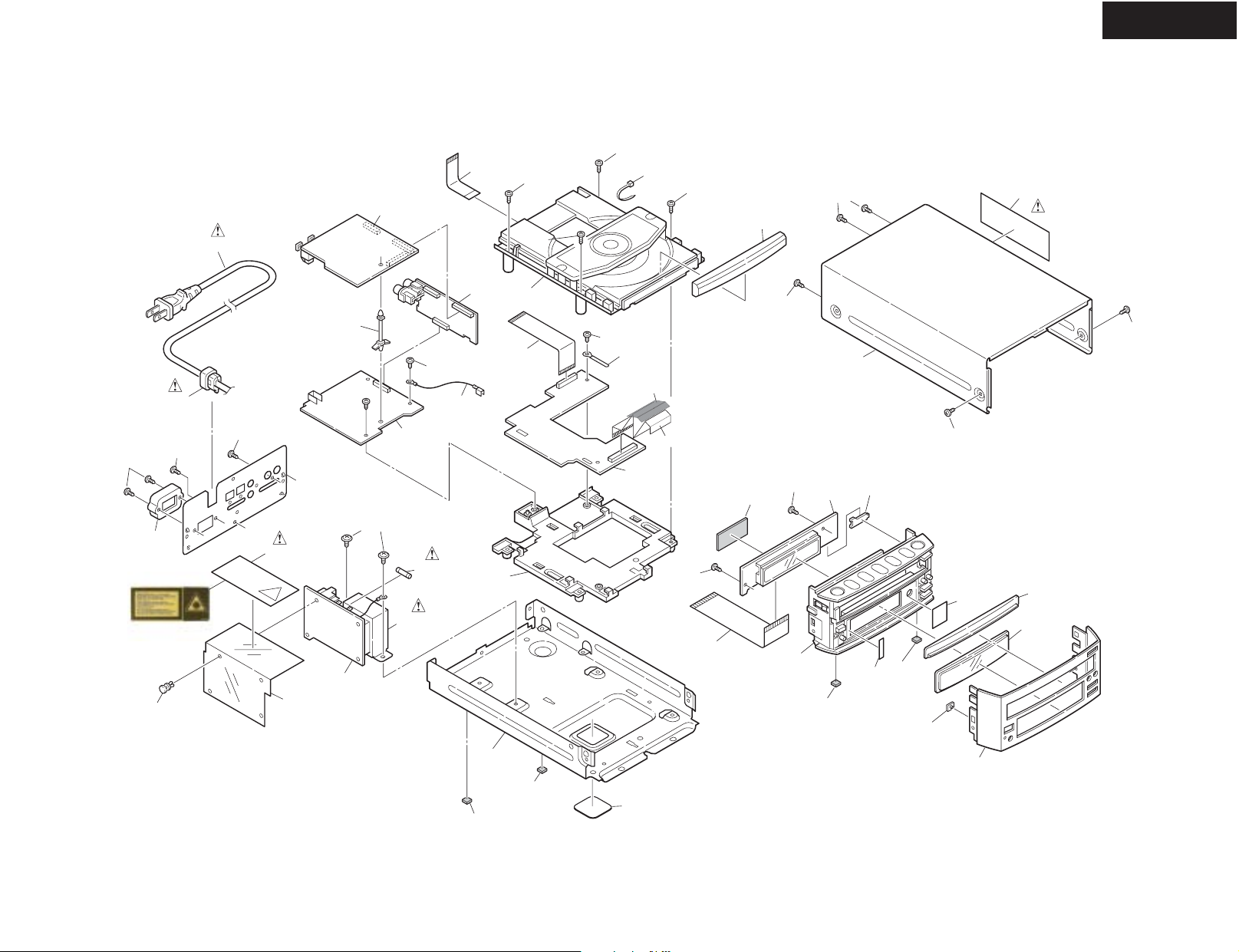
EXPLODED VIEW
P901
A15
A11
U1
A9
J904
P101
U3
A9
Z01
P701
A9
A9
A9
A25
A24
A27
A9
A210
A216
A216
A215
C-701A
A705
A216
<MGR>only
A104
A102
<MGR>only
A18
A103
A103
A105
A17
A101
U6
A13
U5
F901
T901
A1
A219
A5
A219
U2
A221
P701
A9
P701
A23
A20
A9
A219
U4
U7
A108
<MPP>only
A219
A203
A216
A107
A201
A204
A301
Page 6

EXPLODED VIEW PARTS LIST-1
REF. NO. PART NO. DESCRIPTION
A1 27100409 Chassis
A5 27191158A Holder, PCB
A9 838130088 Self tapping screw, 3TTB+8B
A11 27190369 Holder, PCB
A13 830440069 Self tapping screw, 4TTC+6C(BC)
A15 27300750 Bushing, S-RELIEF #2271
A17 27150476 Shield plate (PT)
A18 880048 Plastic rivet, P-3055B-8L
A20 27111246 Front bracket
A23 28141478 Cushion
A24 260208 Wire tie
A25 27255004 Clip, CS-1U
A27 29110083 Tape CROSS-16U 16 x 35mm
A101 27122925 Rear panel <MPP>
27122926 Rear panel <MDT>
27122927 Rear panel <MGR>
27122932 Rear panel <MGT>
A102 27191143 Holder Outlet <MGR>
A103 838430088 Self tapping screw, 3TTB+8B(BC)
A104 838430088 Self tapping screw, 3TTB+8B(BC) <MGR>
A105 29362285 Label
A107 27262674 Plate, WIN1
A108 27262675 Plate, WIN1<MPP>
A201 27212346 Front panel
A203 28198939 Facet (S)
A204 27268055 Guide (Tray)
A210 28148497 Door (Tray)
A215 28184825 Cover
A216 838930088 Self tapping screw, 3TTB+8B(UN)
A219 28141489 Cushion
A221 27262671 Plate (Bottom)
A301 28191952A Clear plate <MPP>
28191944A Clear plate <MDT,MGR,MGT>
A705 29362982 Label (AVIS&CLASS1) <MPP,MGT>
29362939 Label (WARNING) <MDT>
29362991 Label <MGR>
F901 252074 or Fuse, 2A-SE-EAK <MPP,MGR,MGT>
252074CC
J904 2063A14070 Crimp assy
P101 2042161022 Flexible flat cable, NCFC2-161022
P701 2045351022 Flexible flat cable, NCFC5-351022
P703 2047201012
C-701A
<MPP,MDT,MGT>
Flexible flat cable, NCFC7-201012
Page 7

EXPLODED VIEW PARTS LIST-2
REF. NO. PART NO. DESCRIPTION
P901 253335HIT or Power cord, AS-CEE <MPP,MGT>
253336VOL
253332HIT or Power cord, AS-UC-2 <MDT>
253333VOL
253337HIT or Power cord, AS-CCEE <MGR>
253338VOL
T901 2301553 Power transformer, NPT-1426P <MPP>
2301552 Power transformer, NPT-1426D <MDT>
2301555 Power transformer, NPT-1426G <MGR,MGT>
U1 1H477523-1B Main circuit PC board assy NADG-7323-1B <MGT>
1H477523-1C Main circuit PC board assy NADG-7323-1C <MDT>
1H477523-1D Main circuit PC board assy NADG-7323-1D <MGR>
1H477523-1E Main circuit PC board assy NADG-7323-1E <MPP>
U2 1H477524-1B Microprocessor circuit PC board, NADG-7324-1B <MGT>
1H477524-1C Microprocessor circuit PC board, NADG-7324-1C <MDT>
1H477524-1D Microprocessor circuit PC board, NADG-7324-1D <MGR>
1H477524-1E Microprocessor circuit PC board, NADG-7324-1E <MPP>
U3 1H477525-1B Driver circuit PC board assy, NAAF-7325-1B <MGT>
1H477525-1C Driver circuit PC board assy, NAAF-7325-1C <MDT>
1H477525-1D Driver circuit PC board assy, NAAF-7325-1D <MGR>
1H477525-1E Driver circuit PC board assy, NAAF-7325-1E <MPP>
U4 1H477526-1B Display circuit PC board assy, NADIS-7326-1B <MGT>
1H477526-1C Display circuit PC board assy, NADIS-7326-1C <MDT>
1H477526-1D Display circuit PC board assy, NADIS-7326-1D <MGR>
1H477526-1E Display circuit PC board assy, NADIS-7326-1E <MPP>
U5 1H477527-1B Regulator circuit PC board assy, NAPS-7327-1B <MGT>
1H477527-1C Regulator circuit PC board assy, NAPS-7327-1C <MDT>
1H477527-1D Regulator circuit PC board assy, NAPS-7327-1D <MGR>
1H477527-1E Regulator circuit PC board assy, NAPS-7327-1E <MPP>
U6 1H477528-1B Power transformer PC board assy, NAPS-7328-1B <MGT>
1H477528-1C Power transformer PC board assy, NAPS-7328-1C <MDT>
1H477528-1D Power transformer PC board assy, NAPS-7328-1D <MGR>
1H477528-1E Power transformer PC board assy, NAPS-7328-1E <MPP>
U7 1H477529-1B Open/ Close switch PC board assy, NASW-7329-1B <MGT>
1H477529-1C Open/ Close switch PC board assy, NASW-7329-1C <MDT>
1H477529-1D Open/ Close switch PC board assy, NASW-7329-1D <MGR>
1H477529-1E Open/ Close switch PC board assy, NASW-7329-1E <MPP>
Z01 24800018A
C-701A
CD mechanism assy, NCD-170S
<MPP>: European model only
<MDT>: Taiwanese model only
<MGT>: Asian model only
<MGR>: Chinese model only
NOTE: THE COMPONENTS IDENTIFIED BY MARK
ARE CRITICAL FOR RISK OF FIRE AND
ELECTRIC SHOCK. REPLACE ONLY WITH
PART NUMBER SPECIFIED.
Page 8

CD MECHANISM EXPLODED VIEW (1)
6
C-701A
7
9
5
8
10
13
14
15
16
19
20
29
4
3
2
1
28
27
26
6
12
14
15
21
6
11
6
16
17
16
13
14
15
16
12
14
15
18
PARTS LIST
Ref. No. Part No. Description
1 2646-290-01 Tray
2 Stopper
3 2625-544-01 Gear cover
4 2625-535-01 Tray Gear
5 2625-546-01 Chucking plate
6 PTPWH2.6x7, Screw
7 2625-537-01 Chucking yoke
8 1452-493-21 Magnet
9 2625-541-02 Damper
10 2646-291-01 Chucking pulley
11 2646-288-01 Sub chassis
12 2627-236-01 Coil spring (front)
13 2627-235-01 Coil spring (back)
14 2646-289-01 Washer
15 P2.6x10, Screw
-
-
-
25
24
22
23
Ref. No. Part No. Description
16 2627-234-01 Insulator
17
-
Drive unit
18 2625-552-06 Main chassis
19 3319-501-51 PTPWH2.6x16, Screw
20 2625-547-01 Drive Gear
21 2625-545-04 Control cam
22 1692-667-11 Leaf switch
23 1564-721-11 Socket
24 1640-523-11 Loading PC board
25 X2625-117-1 Loading motor
26 2625-274-02 Middle gear
27 2625-536-02 Loading pulley
28 3653-387-00 LM belt
29 B2.6x2.5, Screw
-
The mechanical parts with no part number
in the exploded views are not supplied.
Page 9

CD MECHANISM EXPLODED VIEW (2)
(Pickup drive unit)
C-701A
61
64
53
52
55
60
54
56
59
62
63
51
58
PARTS LIST
Ref. No. Part No. Description
51 X2625-984-1 Motor chassis ass'y
52 X2625-769-1 Motor gear ass'y
53 2656-908-01 Sled shaft
54 2625-188-02 Gear A
55 7621-255-15 P2x3, Screw
56 1572-085-11 Leaf switch
57 1639-678-12 Motor PC board
58 1564-722-11 Socket
59 2627-003-02 Gear B
60 2625-191-01 Coil spring
61 2625-477-01 Center ring
62 2641-386-01 Special screw, 2*5
63 2625-625-01 Reinforcement board
64 8848-483-05 KSS-213C, Pickup
57
Page 10

C-701A
BLOCK DIAGRAM
CD MECHA
NCD-170S
E
D
FOCUS
COIL
TRACKING
COIL
SLED
M
MOTOR
SPINDLE
M
MOTOR
LOADING
M
MOTOR
E
A+C
A
B
B+D
C
F
F
MD
LD
LASER D.
SWITCH
39
36
37
38
35
Q111
34
+5V_2
15
16
17
18
13
14
12
11
9
10 28
STOP
PLAY/
+5V_2
SERVO CONTROLLER
PAUSE
R123
FOCUS
GAIN
ADJUST
CLK
MDP
DRIVER
1
SSTOP
UP/FF
18
19
20
21
22
23
24
SSTOP
OPEN
CLOSE
DOWN/FR
DISPLAY
XLT
DAT
XRST
Q101
RF SIGNAL
PROCESSOR &
CXA2542AQ
155122531
FC
SLD
TR
326 623
Q102 BA5984FP
SLED/SPINDLE/LOADING MOTOR
FOCUS/TRACKING COIL
+5V_3
OPEN_SW
CLOSE_SW
+5V_2
14
13
12
79
11
COUT
10
SENS10
FOK
EFM
MDP
43
42
53
54
ON
STANDBY/
Q401
BUFFER
183521
28
AD0
CLOSE
OPEN/
DOUT
53
XRST
SENS20
37
12
27
AD1
Q301
CXD2589Q
DIGITAL SIGNAL
PROCESSOR
W/DA CONVERTER
8
9
765
4
57
SQSO
SCOR
SQCK
DATA
XLAT
CLOCK
SENS1
1191015161446
DIGIT
Q721
FL DISPLAY
HNA-09SS27T
F1
Q402
OPTICAL
OUT
XTAI
70
XTAO
71
OUT-L
67
74
OUT-R
+5V-1
D751
STBY
36
P1-P17
SEGMENT
F2
16.9344MHZ
LED
STANDBY
Q751
IND. SW
STAND-BY
X701
5MHZ
RESONATOR
Q403
OPTICAL
OUT
15
+5V-2
SCOR
Q701
MICROPROCESSOR
MPD78043FGF-087-3B9
G2-G9
Q705/Q706
FILAMENT
SWITCH
X301
X'TAL
34
35
59
FL ON/OFF
+5V_1
<MJJ> ONLY
Q702
RESET
17
38
+5V_3
+5V_1
POWER ON/OFF
+10V
-10V
Q501-1/2
NJM4565M-D
OP AMP
OP AMP
Q502-1/2
NJM4565M-D
Q712
REMOTE
CONTROL
SENSOR
47
Q904
+5V
REGULATOR
Q901
+5V
REGULATOR
Q902/Q903
+5V
CONTROL
OP AMP
Q501-2/2
NJM4565M-D
+10V
-10V
AMUT
RI OUT
13
+5V_1
+5V_1
Q761/Q762
MUTE
DRIVE
RI IN
18
19
71
OP AMP
Q502-2/2
NJM4565M-D
+5V_1
Q703
BUFFER
-27V+5V_2
Q905
-27V
REGULATOR
Q531
MUTE
SWITCH
Q532
MUTE
SWITCH
5
6
7
8
9
10
NPT-1426
P501
LCH
OUTPUT
RCH
P402
RI
IN/OUT
T901
4
3
2
T.F.
<MPP,MGT>:230-240V AC, 50Hz
<MDT> :120V AC, 60Hz
<MGR> :220-230V AC,50/60Hz
<MJJ> :100V AC, 50/60Hz
1
P903
AC IN
Page 11

C-701A
A
SCHEMATIC DIAGRAM
1
CD Mechanism
NCD-170S
P101B
1
FOCUSING
TRACKING
+5V
2
Vref
M002
SPINDLE
3
MOTOR
SLIDE
MOTOR
CLOSE
M003
LOADING
MOTOR
OPEN
M004
INNNER SW
M005
M006
4
P901
5
P901
16
1
P103B
P102B
5
F901
T2AL250V
P902P902
P903
P903
NAPS-7328 NAAR-7325
FC-
1
TRTR+
FC+
PD
VR
LD
LD-G
F
C
B
A
D
E
VC
FC- FC-
TR- TR-
TR+ TR+
FC+ FC+ CLK
PD PD XLT
VR
LD
LD-G
FF SENS1O
CC
BB
AA
DD
EE
+5VB+5VB
VC
16
P101A
NADG-7323
66
SP+
SP-
SL+
SL-
SSTOP
1
P103A
P102A
5
LD- RCH RCH
LD+ LCH LCH
OPEN_SW
CLOSE_SW GND2
11
TYPE RATING
MJJ AC100V 50/60HZ
MDT AC120V 60HZ
MGR AC220-230V 50/60HZ
MPP AC230-240V 50HZ
MGT AC220-230V 50/60HZ
TYPE P903 F901
MJJ,MDT
MGR
MPP,MGT
T901
5
T.F.
4
2
L901
NCH-3454
Power transformer
U6
PC board
BCDEFGH
L101
100K
C101
100/6.3
R169
4.7K
C191
220/16
P111
T901 P901
NPT-1426J AS-Y
NPT-1426D AS-UC2#18
NPT-1251G AS-CCEE
NPT-1251P AS-CEE
NPT-1251G
NSCT-2P1777 NO
NSCT-2P2508 YES
NSCT-2P1424 YES
AS-CEE
J6
C931
223Z
8
9
10
11
12
13
C192
104Z
C181
C104
103K
C103
103K
FC-
VO4+ 15
VO1+14
SL-
JL905A
VC
FC+
TR+
VO4- 16
VO1-13
SL+
SP-
U1
Main circuit PC board
R125
R176
0
R117
0
0
FOCUS
100/6.3
GAIN
R123
10KB
C110
102K
C109
223K
0
120K
R104
EFDBC
R160
5.6K
R161
Q102
2.2K
R158
R116
120K
R105
10K
OPOUT27 OPOUT322
3.3KR122
R124
0
R120
6.8K
0
R119
100
R121
C107
223K
0
37
R103
1K
47K
R106 47K
R107
TR
R163
R164
R162
2.7K
OPIN3+ 24
OPIN3- 23
OPOUT425
OPIN2+5
OPIN2-6
OPOUT14
R159
2.7K
R156
C186
104Z
C185
104Z
100/6.3
TEST-POINT1
P104
TE2
FE2
TE1
FE2
0
R177
TE2
TE1
C108
474Z
R172
0
R113
150K
R112
R111
100
100K
1SS352
Q111
2SA950-Y
C102
47
47
R102
R101
TR-
GND 19
BIAS 20
MUTE 21
VO3+ 17
VO3- 18
BA5984FP
VCC8
VO2+12
VO2-11
VOL+10
VOL9
SP+
LD-
LD+
C182
FE1
FE1
R173
D101
100/6.3
VC
R171
R155
NAPS-7327
U5
Regulator circuit PCboard
NJM78M05FA
D901-D904,D906
RL1N4003
JL905B
D904
C901
D901
3300/16
D902
C902
3300/16
D903
D906
R908
334TF
C923
334TF
C922
334 C921
C909
C908
47/35
R907*
100/50
0
PD2
FC
SLD
5.6K
F38
OPIN4- 26
OPIN1-3
D907
C121
FEO48
FZC47
VC46
TDFCT45
TZC44
ATSC43
LPFI42
TEO41
VEE40
E39
47K
R108
3.9K
3.9K
I
222K
C122
FEI
A
C158
10K
R165
OPIN4+ 27
OPIN1+2
R157
10K
CLOSE
Q904
G
Q905
2SA950-Y
1
PD136
2.2/50
REV 28
FWD1
O
UDZ27B
FC
1M
R126
474Z
C124
104K
R128
104K
C123
FGD 3
FLB 4
FE_O 5
FDFECT 2
Q101
CXA2542AQ
LD34
PD35
RFTC33
RF_M32
R138
15K
47K
R109
0
C157 020C
R179
PD
12K
R139
1M
R141
2.7K
2.7K
OPEN
100/16
C907
Q901
NJM78M05FA
I
O
G
C903
220/16
TYPE MPP OTHER
R907 5.6(1/2W)
C910
47/35
NADG-7324
Microprocessor circuit PC board
U2
D701
UDZ
5.1B
R702
R703
100
4.7K
C721
223Z
SQCK
1K
R789
1K
XLAT
C701
100/6.3
P702A
Q705
2SC2120-Y
R701
100
R781
DATA
CLOCK
1K
R710
0
C702
223Z
100/6.3
R792
1KR791
R790
1K
P702B
NADIS-7326
JL912A
-VDISP F1
F1
F2 G3 P5
P703A
O_SW AMUTE
P_ON/OFF
P703B
0
DIGITAL
OUT
NASW-7329
1
2
S701
OPEN/CLOSE
U7
Open/close
RI
switch PC
board
AUDIO
OUT
Lch
Rch
P501
3.3K
22K
PCO
FILO
FILI
FILI 31
PCO 29
FILO 30
Q301
CXD2589Q
XTAI70
XTAO71
XVSS
72
MCK
R333
1M
16.9344MHZ
X301
150
C357
C401
100/6.3
RI
Q501
3
2
2
3
Q502
C313
152K
CLTV
CLTV 33
AVSS1 32
XVDD69
AVSS368
150
C356
DOUT
8
4
R507
R508 2.2K
4
8
R325
1MR324
C314
101J
35
RF
BIAS 36
AVDD1 34
AIN166
AOUT165
LOUT1
67
C331
151J
C335
22/35
LCH
Q401
TC7WT241FU
8
VCC
7
G
Y16Y2
5
A2
1
C501
220J
2.2K
C502
220J
1
R327
R328
ASYI 37
LRCK 39
ASYO 38
PCMDI42
BCKI 44
VSS3 45
VDD246
XUGF47
C2PO50
XTSL 51
DOUT53
EMPH54
EMPHI
WFCK56
SCOR57
EXCK59
SYSM62
AVDD264
AVSS263
R343
12K
R345
12K
AMUTE
Q761
RN1407
GND
6
5
Q501
NJM4565M-D
0
R515
5
6
NJM4565M-D
100K
10K
40
LRCKI
PCMD
BCK 43
GFS
C4M52
VSS4
VDD3
61
C341
R332
10K
C333
D761
1SS352
1
G
2
A1
3
4
C533
0.47/50
C503
47/50
C504
47/50
Q502
41
49
55
60
XRST
7
7
R341
681J
R347
C315
104Z
12K
0
RN2403
R533
470K
0.47/50
DOUT
SCOR
C352
Q762
C451
101J
C316
103K
C321
104Z
104Z
SENS20
C761
R451 470
R509
220K
R510
220K
0
R331
0
R334
DOUT
CLOSE CLOSE
OPEN OPEN
C_SW C_SW C_SW
O_SW
P_ON/OFF
RI RI SQSO
+5VA +5VA
CLOCK CLOCK
XLAT XLAT
DATA DATA CLOSE
SENS1 OPEN
SQSO
SQCK SQCK
SCOR
XRST XRST
SENS20
R142
D762
1SS352
C762
220/6.3
102J
Q402
GP1FA
C403
550TZ
223Z
C404
Q403
223Z
GP1FA
550TZ
0
R403
P451
C452
223Z
R511
Q531
RN1441
1K
R531
1K
C531
104Z
C534
222K
104Z
C532
R532
1K
Q532
R512
RN1441
1K
TR
R175
0
C128
103K
C126
39K
4.7/50
R130
R133
R129
470K
C130
33K
R131
C129
101J
C125
101J
FE_M 6
RF_O31
R140
82K
C155
4.7K
C156
SRCH 7
RF_I30
222K
220J
R132
C127
10K
104K
12
TA_O
TG2 9
TGU 8
FSET 10
TA_M 11
SL_P
13
SL_M 14
SL_O 15
ISET 16
VCC 17
CLK 18
XLT 19
DATA 20
21
XRST
C.OUT 22
SENS1 23
24
SENS2
FOK25
CB28
CC127
CC226
CP29
C152
333K
RFO EFM
C154
103K
103K
C153
RFO AMUTE AMUTE SENS1
VC
P105
TR+
TR+
103K
C161
MDP
R153
R152
4.7K
10K
Q902
2SA950-Y
C905
R901
100/6.3
10K
1K
R902
Q903
RN1403
C904
220/6.3
R903
SLD
R174
0
R135
8.2K
4.7K
C131
3.3/50
33/35
C141
101J
R136
47K
R137
DAT
XRST
COUT
FOK FOK G9
C151
103K
TR
FC-
TR-
FC+
TR
FC-
TR-
FC+
10K
R151
10K
C183
120K
C143
101J
FC
SLD
MDP
OPEN
SSTOP
CLOSE
VC
FC
VC
SLD
MDP
OPEN
SSTOP
CLOSE
P911A
+5V
GND
P_ON/OFF P_ON/OFF
+5VB +5VB
GND
GND
GND
GND
-10V -10V
+10V +10V
C184
100/6.3
C142
104K
C_SW
CLOSE_SW
P911B
+5V
GND1
+5VA
GND2
GND3
GND4
GND5
104Z
SENS1O
O_SW
OPEN_SW
MDP
CLK
XLT
DAT
COUT
P914B
P914A
SSTOP
COUT
SENS1O
SENS20
MDP
EFM
FOK
CLK
XLT
DAT
P904
R321 1K
1K
R326
C305 104K
R318
R317
R316
R315
R314
R313
R312
R311
CLOCK
XLAT
DATA EMPH
SENS1
SQSO
SQCK
R338
1K
SCOR RI.IN RMCN
XRST RI.OUT SCOR
C391
220/6.3
C394
220/6.3
OPEN
CLOSE
C_SW
O_SW
MUTE
GND7
GND3 AD0 AD0 AD0
+5VB +5VB
+5VA +5VA
P_ON/OFF
R761
1K
20
1K
10K
1K
15
1K
1K
13 XPCK48
1K
1K
1K
8
1
VSS1
C343
104Z
C301
100/6.3
C337
223Z
R337
1K
K
L391
100
C392
104Z
L392 100K
104Z
C395
P_ON/OFF
P913A
P913B
R905 220
R906
C312
473K
R323
3.3K
R322
21
23
MDP
VDD4
80
VCKI 26
TES1 24
TEST
VCTL 28
V16M 27
PWMI 22
VPCO 25
AIN275
AOUT276
LOUT274
XRST79
AVDD377
AVSS473
AVSS578
VSS2
VDD119
FOK18
XLON17
SPOB16
SPOA
CLKO14
XLTO
DATO12
CNIN11
SEIN10
CLOK9
XLAT
DATA7
SENS6
SQSO5
SQCK4
RMUT3 SBSO58
LMUT2
XRST
C351
220/6.3
C342
104Z
R344
12K
R342
C332
12K
151J
R346
12K
C336
22/35
C334
681J
RCH
RI
MUTE
NJM4565M-D
100
R501
220K
R503
R505
2.7K
R506
2.7K
R504
220K
R502
100
NJM4565M-D
C592
220
C591
100/16
100/16
TO CD MECHA
2.2(1/2W)
JL912B
GND
-VDISP
F1
F2
U3
Driver circuit PC board
R704
10K
R705
10K
Q706
2SC2120-Y
R783
1K
R785
1K
R787
1K
R711
4.7K
Q702
BMR-0101D
O
V
G
C703
223Z
223Z
SENS20
P701B
P701A
SCOR
SQSO
SENS1
P17
P17
C704
P16G2P15G3P14G4P13G5P12
P16G2P15G3P14G4P13G5P12
C707
R7341KR733
S705
S704
STOP
Q721
HNA-09SS27T
8G5
F11
F1'2
G76
G9
4
F1G9G8G7G6G5G4G3G2
G2
P17
P16
P15
P14
FL_OFF
F2A
G1 79
G2 80
P15 75
P16 76
P17 77
G31
21
22
24
C705
NC20 78
G42
G53
G64
G75
G86
7
G9
VDD18
CLK9
DATA10
XLT11
SENS212
AMUT13
SQCK14
SENS15
SQSO16
RESET17
RI_IN18
RI_OUT19
AVSS20
NC1
NC2
NC323
NC4
NC6
AD127
NC5
25
26
C706
103K
103K
MPD78043FGF
-087-3B9
AD028
AVDD
AVREF
29
30
G4 P4
G5 P3
G6 P2
G7 P1
G8 FL_OFF
SENS20 O_SW
47K
D702
1SS352
Q703
RN2403
R722
2.7K
D703
R713
220K R712
RI
UDZ5.6B
R721
2.7K
CSTS5.00MGW
AD1
AD0
G6
G7
G9
P9
G9
P9
STANDBY/ON
P1320
P1419
P1518
P14
P13
P7
AD1P6AD0P5F2A
RMCNP8STBY
P7
AD1P6AD0P5F2A
RMCNP8STBY
AD1
P1023
P1122
P1221
P9
24
P9P8P7P6P5P4P3P2P1
P12
P11
P10
P825
P11G8P10
-VDISP
G6
G7
P11G8P10
-VDISP
R732
R731
470
820
S703
PLAY/PAUSE
UP/FF
S702
390
DOWN/FR
R741
390
S707
DISPLAY
NC1
G112
G211
G310
G49
G58
G67
U4
NC214NC315
P1617
P1716
13
P17
P16
R798
100K
-VDISP
R796
100K*9
Display circuit PC board
S706
P15
P13
P12
P12 72
P13 73
P14 74
Q701
VSS233
NC7
VSS131
32
X701
D751
SLR-332VR
P528
P627
P726
R797
100K*8
P9P8P7
P11
P10
-VDISP
P9 68
P10 69
P11 70
-VDISP 71
DSP_RESET37
STBY_LED36
X235
X134
R723
XRST
STBY
P4F1P3
P4F1P3P2P1
P231
P330
P429
P6
P6 65
P7 66
P8 67
P5 64
P4 63
P3 62
P2 61
P1 60
FL_OFF 59
NC19
NC18
NC17
NC16
CLOSE_SW54
OPEN_SW53
VDD2 52
NC15
NC14
NC13
VSS3 48
RMCN47
SCOR 46
NC12
NC11
CLOSE 43
OPEN 42
P_ON/OFF38
NC839NC940
0
P_ON/OFF
P2
+5VA
F2'34
P132
P5P4P3P2P1
58
57
56
55
51
50
49
45
44
41
NC10
10K
R724
223Z
C751
P1
C712
R730 NO YES
C711 YES
F235
F2A
10K
R726
Q751
RN1407
470
R751
STBY
10K
R730
*
100/6.3
MJJ OTHER
FL_OFF
10K
R727
Q711
GP1U271X
C711
223Z
*
NO
Page 12

A
SCHEMATIC DIAGRAM
1
CD Mechanism
NCD-170S
P101B
1
FOCUSING
TRACKING
+5V
2
Vref
M002
SPINDLE
3
MOTOR
SLIDE
MOTOR
CLOSE
M003
LOADING
MOTOR
OPEN
M004
INNNER SW
M005
M006
4
1
P103B
P102B
5
16
FCTRTR+
FC+
PD
VR
LD
LD-G
F
C
B
A
D
E
VC
BCDEFGH
U1
Main circuit PC board
FC
3.3KR122
R124
R120
0
100
1K
47K
R107
0
6.8K
37
1M
R126
C121
222K
0
C122
FEI
FEO48
FZC47
VC46
TDFCT45
TZC44
ATSC43
LPFI42
TEO41
VEE40
E39
F38
PD2
47K
R108
C158
1
PD136
R179
A
2.2/50
474Z
C123
FDFECT 2
PD35
47K
R109
PD
104K
FGD 3
LD34
0
C126
C124
104K
82K
R128
FLB 4
FE_M 6
FE_O 5
Q101
CXA2542AQ
RFTC33
RF_M32
RF_O31
R138
C155
15K
R140
4.7K
C157 020C
12K
C156
R139
1M
R141
R125
C182
VC
C185
100/6.3
R172
0
R113
R101
C108
474Z
R112
100K
Q111
2SA950-Y
C186
104Z
104Z
TEST-POINT1
P104
TE2
FE1
FE2
TE1
FE2
0
R177
TE2
TE1
FE1
R173
150K
R111
D101
100
1SS352
C102
100/6.3
47
47
R102
VC
0
R171
R176
R117
0
100/6.3
0
0
FOCUS
GAIN
R123
10KB
C110
102K
R119
R121
C109
223K
R116
0
120K
R105
120K
R104
EFDBC
C107
223K
R106 47K
R103
C181
1
FC- FC-
TR- TR-
TR+ TR+
FC+ FC+ CLK
PD PD XLT
VR
LD
LD-G
FF SENS1O
CC
BB
AA
DD
EE
+5VB+5VB
VC
16
P101A
C101
100/6.3
L101
100K
C104
103K
C103
103K
NADG-7323
TR
FC-
FC+
TR+
C192
104Z
TR-
VO3+ 17
VO4+ 15
VO4- 16
VO1+14
VO1-13
VO2+12
SL-
SL+
SP-
SP+
GND 19
BIAS 20
MUTE 21
VO3- 18
BA5984FP
VCC8
VO2-11
VOL+10
VOL9
LD-
LD+
66
SP+
SP-
SL+
SL-
SSTOP
1
R169
4.7K
P103A
C191
220/16
P102A
5
LD- RCH RCH
LD+ LCH LCH
OPEN_SW
CLOSE_SW GND2
11
P111
10K
R160
5.6K
R161
Q102
OPOUT27 OPOUT322
2.2K
R158
FC
10K
R163
3.9K
R164
R162
2.7K
R165
2.7K
REV 28
OPIN3+ 24
OPIN3- 23
OPIN4+ 27
OPIN4- 26
OPOUT425
FWD1
OPIN1+2
OPIN1-3
OPIN2+5
OPIN2-6
OPOUT14
R159
2.7K
2.7K
R157
R156
R155
SLD
3.9K
10K
CLOSE
MDP
OPEN
TR
R175
0
C128
103K
39K
4.7/50
R130
R133
R129
470K
C130
33K
R131
C129
101J
C125
101J
R132
C127
10K
104K
12
TA_O
TG2 9
TGU 8
FSET 10
SRCH 7
TA_M 11
SL_P
13
SL_M 14
SL_O 15
ISET 16
VCC 17
CLK 18
XLT 19
DATA 20
21
XRST
C.OUT 22
SENS1 23
24
SENS2
FOK25
CB28
CC127
CC226
CP29
RF_I30
C152
222K
220J
333K
RFO EFM
C154
103K
103K
C153
RFO AMUTE AMUTE SENS1
VC
P105
TR+
TR+
103K
C161
R153
R152
4.7K
10K
SLD
R174
0
R135
8.2K
4.7K
C131
3.3/50
33/35
C141
101J
C143
101J
FC
FC
120K
C183
SLD
MDP
OPEN
SSTOP
CLOSE
VC
VC
SLD
MDP
OPEN
SSTOP
CLOSE
R136
47K
R137
DAT
XRST
COUT
FOK FOK G9
C151
103K
TR
FC-
TR-
FC+
TR
FC-
TR-
FC+
10K
R151
C184
100/6.3
C142
104K
C_SW
CLOSE_SW
104Z
SENS1O
O_SW
OPEN_SW
MDP
CLK
XLT
DAT
COUT
P914B
P914A
SSTOP
COUT
SENS1O
SENS20
MDP
EFM
FOK
CLK
XLT
DAT
R321 1K
1K
R326
C305 104K
1K
R318
R317
10K
R316
1K
R315
1K
R314
1K
R313
1K
R312
1K
1K
R311
CLOCK
XLAT
DATA EMPH
SENS1
SQSO
SQCK
C301
100/6.3
R338
1K
C337
223Z
SCOR RI.IN RMCN
XRST RI.OUT SCOR
CLOSE
GND7
P_ON/OFF
R337
1K
K
L391
100
C392
104Z
C391
220/6.3
104Z
C394
C395
220/6.3
OPEN
C_SW
O_SW
MUTE
GND3 AD0 AD0 AD0
+5VB +5VB
+5VA +5VA
P913A
20
15
13 XPCK48
8
1
VSS1
C343
104Z
L392 100K
P_ON/OFF
P913B
JL905A
NAPS-7327
U5
Regulator circuit PCboard
D901-D904,D906
RL1N4003
JL905B
D904
D901
D902
D903
D906
334TF
C923
334TF
C922
334 C921
R907*
C908
100/50
C901
3300/16
C902
3300/16
C909
R908
47/35
Q904
NJM78M05FA
I
G
5.6K
D907
O
NJM78M05FA
C903
Q905
2SA950-Y
C910
UDZ27B
C907
Q901
I
220/16
47/35
Q902
2SA950-Y
100/16
R901
10K
1K
R902
O
G
TYPE MPP OTHER
R907 5.6(1/2W)
C904
RN1403
220/6.3
2.2(1/2W)
100/6.3
Q903
C905
R903
10K
P904
TO CD MECHA
P911A
GND
GND
GND
GND
JL912B
P911B
+5V
GND1
+5VA
GND2
GND3
GND4
GND5
+5V
P_ON/OFF P_ON/OFF
+5VB +5VB
GND
-10V -10V
+10V +10V
GND
-VDISP
F1
F2
R905 220
R761
1K
R906
U3
Driver circuit PC board
TYPE RATING
MJJ AC100V 50/60HZ
MDT AC120V 60HZ
MGR AC220-230V 50/60HZ
MPP AC230-240V 50HZ
MGT AC220-230V 50/60HZ
F901
T2AL250V
P902P902
P901
P903
5
5
P901
4
T901 P901
NPT-1426J AS-Y
NPT-1426D AS-UC2#18
NPT-1251G AS-CCEE
NPT-1251P AS-CEE
NPT-1251G
TYPE P903 F901
MJJ,MDT
NSCT-2P1777 NO
MGR
NSCT-2P2508 YES
MPP,MGT
NSCT-2P1424 YES
T901
C931
223Z
8
T.F.
9
10
AS-CEE
J6
11
P903
2
L901
NCH-3454
Power transformer
NAPS-7328 NAAR-7325
U6
PC board
12
13
Page 13

C-701A
R325
1MR324
C336
V16M 27
LOUT274
22/35
3.3K
22K
R322
PCO
FILO
PCO 29
FILO 30
VCTL 28
Q301
CXD2589Q
XTAO71
XVSS
AVSS473
72
MCK
16.9344MHZ
X301
C357
RCH
RI
FILI
R333
150
C313
152K
C314
101J
CLTV
35
RF
FILI 31
XTAI70
1M
AVSS1 32
XVDD69
C356
DOUT
ASYI 37
BIAS 36
CLTV 33
AVDD1 34
AIN166
AOUT165
LOUT1
AVDD264
AVSS368
67
C331
R343
12K
151J
R345
150
C335
22/35
LCH
C312
473K
R323
3.3K
21
23
MDP
VDD4
80
C351
PWMI 22
XRST79
XRST
R342
C334
12K
681J
TEST
AVSS578
C342
104Z
R344
12K
R346
12K
VCKI 26
TES1 24
VPCO 25
AIN275
AOUT276
AVDD377
C332
151J
VSS2
20
VDD119
FOK18
XLON17
SPOB16
SPOA
15
CLKO14
13 XPCK48
XLTO
DATO12
CNIN11
SEIN10
CLOK9
XLAT
8
DATA7
SENS6
SQSO5
SQCK4
RMUT3 SBSO58
LMUT2
1
VSS1
C343
104Z
220/6.3
L392 100K
P_ON/OFF
RN1407
MUTE
C401
100/6.3
Q401
TC7WT241FU
8
VCC
7
G
Y16Y2
5
A2
P913B
RI
R905 220
Q501
NJM4565M-D
100
R501
220K
R503
R505
2.7K
R506
2.7K
R504
220K
R502
100
NJM4565M-D
3
2
2
3
Q502
8
C501
4
220J
R507
R508 2.2K
C502
4
220J
8
1
1
6
5
R515
2.2K
5
6
R906
C592
220
C591
100/16
100/16
100K
R327
R328
10K
40
LRCKI
PCMD
LRCK 39
ASYO 38
PCMDI42
BCK 43
BCKI 44
VSS3 45
VDD246
XUGF47
GFS
C2PO50
XTSL 51
C4M52
DOUT53
EMPH54
EMPHI
WFCK56
SCOR57
EXCK59
VSS4
SYSM62
VDD3
AVSS263
61
C341
R332
10K
12K
C333
AMUTE
D761
1SS352
Q761
1
G
2
A1
3
4
GND
C533
0.47/50
Q501
NJM4565M-D
0
C503
47/50
C504
47/50
Q502
NJM4565M-D
41
49
55
60
7
7
104Z
R341
681J
R347
XRST
C315
0.47/50
DOUT
SCOR
12K
0
Q762
RN2403
R533
470K
C451
101J
103K
C321
104Z
104Z
C352
SENS20
C761
R451 470
R509
220K
R510
220K
C316
NADG-7324
Microprocessor circuit PC board
U2
D701
UDZ
5.1B
R702
R703
100
4.7K
C721
223Z
SQCK
1K
R789
1K
XLAT
C701
100/6.3
Q705
2SC2120-Y
R701
100
DATA
CLOCK
C702
R790
JL912A
-VDISP F1
F1
0
R331
0
R334
DOUT
CLOSE CLOSE
OPEN OPEN
C_SW C_SW C_SW
O_SW
P_ON/OFF
RI RI SQSO
+5VA +5VA
CLOCK CLOCK
XLAT XLAT
DATA DATA CLOSE
SENS1 OPEN
SQSO
SQCK SQCK
SCOR
XRST XRST
SENS20
R142
D762
1SS352
C762
220/6.3
F2 G3 P5
P703A
O_SW AMUTE
P_ON/OFF
P703B
0
102J
Q402
DIGITAL
GP1FA
C452
223Z
C534
C403
223Z
C404
223Z
P451
R531
R532
1K
1K
R511
222K
C532
R512
1K
1K
R403
C531
0
Q531
RN1441
104Z
104Z
Q532
RN1441
550TZ
Q403
GP1FA
550TZ
OUT
NASW-7329
1
2
U7
RI
AUDIO
OUT
Lch
Rch
P501
S701
OPEN/CLOSE
Open/close
switch PC
board
P702A
R704
10K
R705
10K
Q706
2SC2120-Y
R781
R783
1K
1K
R785
1K
R787
1K
R711
4.7K
Q702
BMR-0101D
R710
0
O
V
G
223Z
C703
223Z
C707
100/6.3
R792
1KR791
1K
SCOR
SQSO
SENS1
SENS20
P17
P16G2P15G3P14G4P13G5P12
P701B
P701A
P17
P16G2P15G3P14G4P13G5P12
P702B
R7341KR733
S705
STOP
Q721
HNA-09SS27T
8G5
F11
F1'2
G9
4
F1G9G8G7G6G5G4G3G2
NADIS-7326
FL_OFF
F2A
G4 P4
G5 P3
G6 P2
G7 P1
G8 FL_OFF
SENS20 O_SW
223Z
C704
47K
D702
1SS352
Q703
RN2403
D703
R713
220K R712
RI
UDZ5.6B
G6
G6
R732
470
820
S703
S704
PLAY/PAUSE
UP/FF
NC1
G112
G211
G310
G49
G58
G67
G76
U4
13
R798
-VDISP
Display circuit PC board
-VDISP
-VDISP
S702
S707
100K
R721
2.7K
NC214NC315
R722
2.7K
G7
G7
P11G8P10
P11G8P10
P17
7
21
22
24
C705
R731
390
DOWN/FR
R741
390
S706
DISPLAY
P1617
P1716
P16
P15
R796
100K*9
G2
P17
P16
G1 79
G2 80
P17 77
G31
NC20 78
G42
G53
G64
G75
G86
G9
VDD18
CLK9
DATA10
XLT11
MPD78043FGF
SENS212
AMUT13
-087-3B9
SQCK14
SENS15
SQSO16
RESET17
RI_IN18
RI_OUT19
AVSS20
NC1
NC2
NC323
NC4
NC6
AD028
AD127
NC5
25
26
C706
103K
103K
AD1
AD0
G9
P9
RMCNP8STBY
G9
P9
RMCNP8STBY
AD1
STANDBY/ON
P1023
P1122
P1221
P1320
P1419
P1518
P14
P13
P12
P11
P10
P15
P14
P13
P13 73
P14 74
P15 75
P16 76
Q701
NC7
VSS131
AVDD
AVREF
32
29
30
CSTS5.00MGW
P7
AD1P6AD0P5F2A
P7
AD1P6AD0P5F2A
P726
P825
P9
24
P9P8P7P6P5P4P3P2P1
R797
100K*8
P12
-VDISP
P12 72
-VDISP 71
X134
VSS233
X701
D751
SLR-332VR
P528
P627
P11
P429
P9P8P7
P6
P10
P7 66
P8 67
P9 68
P10 69
P11 70
FL_OFF 59
NC19
NC18
NC17
NC16
CLOSE_SW54
OPEN_SW53
VDD2 52
NC15
NC14
NC13
VSS3 48
RMCN47
SCOR 46
NC12
NC11
CLOSE 43
OPEN 42
DSP_RESET37
STBY_LED36
P_ON/OFF38
X235
NC839NC940
0
R723
XRST
STBY
P4F1P3
P2
+5VA
P4F1P3P2P1
F2'34
P132
P231
P330
P6 65
P5 64
P4 63
P3 62
P2 61
P1 60
58
57
56
55
51
50
49
45
44
41
NC10
P_ON/OFF
10K
R724
223Z
C751
P1
C712
R730 NO YES
C711 YES
F235
F2A
P5P4P3P2P1
10K
R726
Q751
RN1407
470
R751
STBY
10K
R730
*
100/6.3
MJJ OTHER
FL_OFF
10K
R727
Q711
GP1U271X
C711
223Z
*
NO
Page 14

PC BOARD CONNECTION VIEW
9
41
S-7327
C
y
d
6
C
d
SW
03B
03A
B
P7
JL905A
B
U4
U3
U5: Regulator circuit PC board
U5
C-701A
AC IN
MPP,MGT : 230-240V AC, 50Hz
MDT : 120V AC, 60Hz
MGR : 220-230V AC, 50/60Hz
WHT
BLK
P902
F901
U2
U2: Microprocessor
circuit PC board
JL912A
AC-G AC-H
P903
NAPS-7328
board
: Power transformer P
P7
NADG-7324
JL905
JL912B
: Driver circuit
PC board
P913A
P911B
P103A
11A
NAP
U1
U1: Main circuit PC board
NADG-7323
P913B
P105
P102A
P701A
P914B
CLOSE
OPEN
C-SW
P7
GND
O-SW
P-ON
AMUTERI+5VA
GND
GND
CLOCK
XLAT
DATA
SENS
SQSO
SQOK
SQCK
SCOR
XRST
SENS20
P914A
U7: Open/close
U7
switch P
boar
NA
P701
NAAF-7325
: Displa
circuit PC boar
NADIS-732
P104
P101A
Page 15

PRINTED CIRCUIT BOARD PARTS LIST-1
o
k
C-701A
U1: Main circuit PC board
(NADG-7323-1B/1C/1D/1E)
CIRCUIT NO. PART NO. DESCRIPTION CIRCUIT NO. PART NO. DESCRIPTION
ICs ICs
Q101 22241661R3 CXA2542AQ Q701 22241694R3 MPD78043FGF-087-3B9
Q301 22241500R3 CXD2589Q Q702 22241210 BMR-0101D
Q401 22241546R2 TC7WT241FU Transistors
Photo couplers Q703 2214540R2 RN2403
Q402,Q403 24120082 GP1FA550TZ Q705,Q706 2211164 2SC2120-Y
Transistors Q751 2216260R2 RN1407
Q111 2211504 2SA950-Y Oscillator
Q761 2216260R2 RN1407 X701 3010343 CSTS0500MG06
Q762 2214540R2 RN2403 Diodes
Resonator D701 224490510R2 UDZ5.1B, Zener
X301 3010308 HC-49/U0316.9344M D702 223234R2 or 1SS352 or
Diodes 223269R2 1SS355
D101,D761, 223234R2 or 1SS352 or D703 224490560R2
D762 223269R2 1SS355 224550560R2 UDZS5.6B
Coils Sockets
L101,L391, 231237K100R2, Cho
L392 P703A 25052216 NSCT-20P2113
Sockets JL912A 25051088 NSCT-4P875
P101A 25052316 NSCT-16P2213 Capacitors
P101A or 25052510 NSCT-16P2407 C701 354721019 100uF,6.3V,Elect.
P703B 25052216 NSCT-20P2113 C712 353721019 100uF,6.3V,Elect.
P913B 25051234 NSCT-9P1024
P914B 25051240 NSCT-15P1030 U3: Motor driver circuit PC board
Plugs (NAAF-7325-1B/1C/1D/1E)
P104,P105 25056132 NPLG-2P1071
Jack
P451 25045601 NPJ-2PDB409, Q102 22241696R2 BA5984FP
Capacitors Transistors
C101,C102, 354721019 100uF,6.3V,Elect. Q531,Q532 2215410R2 RN1441
C181-C183, Socket AS
C301 P102A 2002A391025 NSAS-10P0871
C126 354780479 4.7uF,50V,Elect P103A 2002A391220 NSAS-12P0846
C130 354763309 33uF,35V,Elect Socket
C131 354780339 33uF,50V,Elect P911B 25051237 NSCT-12P1027
C158 393380227 2.2uF,50V, (VX) Elect. Plugs
C315 353784799 0.47uF,50V,Elect P913A 25055705 NPLG-9P661
C335,C336 353762209 22uF,35V,Elect P914A 25055711 NPLG-15P667
C351,C391, 354722219 220uF,6.3V,Elect Jack
C394,C762 P501 25045628 NPJ-2PDRW435,
C401 354721019 100uF,6.3V,Elect Audio out
Resistor Capacitors
R123 5210262 N06HR10KBC, Trimmer C191 354742219 220uF,16V,Elect.
NCH-1475 P701B 25052372 NSCT-35P2269
RI terminal Q501,Q502 22241383R2 NJM4565M-D
U2: Microprocessor circuit PC board
(NADG-7324-1B/1C/1D/1E)
UDZ5.6B or
CIRCUIT NO. PART NO. DESCRIPTION
ICs
C503,C504 354784709 47uF,50V,Elect.
C533 354784799 0.47uF,50V,Elect.
C591,C592 354741019 100uF,16V,Elect.
Page 16

C-701A
PRINTED CIRCUIT BOARD PARTS LIST-2
U4: Display circuit PC board (NADIS-7326-1B/1C/1D/1E) U6: Power transformer PC board (NAPS-7328-1B/1C/1D/1E)
CIRCUIT NO. PART NO. DESCRIPTION CIRCUIT NO. PART NO. DESCRIPTION
FL tube Coils
Q721 212224 HNA-09SS28T L901 231222 NCH-3454,Choke
LED
D751 225338 SLR-332VR(h1=8mm) Fuse holders
Socket AS F901A,F901B 25050065
P702 200EE390408 NSAS-4P0893 Sockets
Socket JL905A 25051110 NSCT-6P897
P701A 25052372 NSCT-35P2269 P903 25051637 NSCT-2P1424, Outlet
Holder terminal <MPP,MGT>
Q721A 27191157 FL P903 25051990 NSCT-2P1777, Outlet
Switches terminal <MDT>
S702-S706 25035699 NPS-111-S662 P903 25052611 NSCT-2P2508, Outlet
U5: Power regulator circuit PC board (NAPS-7327-1B/1C/1D/1E) PLug
CIRCUIT NO. PART NO. DESCRIPTION
ICs
Q901,Q904 222780055JRC NJM78M05FA U7: Open/Close switch PC board (NAPS-7329-1B/1C/1D/1E)
Transistors
Q902,Q905 2211504 2SA950-Y Switch
Q903 2214480R2 RN1403 S701 25035699 NPS-111-S662, Open/Close
Diodes
D901-D904, 22380260 or RL1N4003 or
D906 22380035 GP104003E
D907 224492700R2 UDZ27B, Zener
Socket
JL905B 25050270 NSCT-6P98
Plugs
JL912B 25055625 NPLG-4P587
P911A 25055708 NPLG-12P664
Capacitors
C901,C902 394043327S 3300uF,16V,Elect. (RS)
C903,C904 354742219 220uF,6.3V,Elect.
C905 354721019 100uF,6.3V,Elect.
C907 354741019 100uF,16V,Elect.
C908 354781019 100uF,50V,Elect.
C909,C910 354764709 47uF,35V,Elect.
C921-C923 374723344 0.33uF+/-5%,50V,Plastic.
Resistors
R907 453530564 5.6 ohm+/-5%,1/2W, Metal
<MPP>
R907 453530224 2.2 ohm+/-5%,1/2W, Metal
<MGR,MDT,MGT>
Heat sinks
Q901A ,Q904A 27160492 RAD-158
Screws
Q901B,Q904B 82143010
3P+10FN(BC)
P902 25055676 NPLG-2P632
CIRCUIT NO. PART NO. DESCRIPTION
<MPP> : European model only
<MDT> : Taiwanese model only
<MGT> : Asian model only
<MGR> : Chinese model only
<MPP,MGR,MDT,MGT>
YSH403T
<MPP,MGR,MGT>
terminal <MGR>
Page 17

MICROPROCESSOR TERMINAL DESCRIPTION
Q701: uPD78043FGF
No. SIGNAL I/O DESCRIPTION No. SIGNAL I/O DESCRIPTION
1 3G O 36 STANDBY LED O Standby LED control terminal. H=ON, L=OFF
2 4G O 37 DSP RESET O Reset output terminal to signal processing IC.
3 5G O 38 POWER O Power source control output terminal. H=ON, L=OFF
4 6G O Grid control output terminals(G3-G9) 39 O
5 7G O | O Not used. (Open)
68G O 41 O
7 9G O 42 OPEN O Tray control output terminal.
8 +5V I Power supply +5V 43 CLOSE O Tray control output terminal.
9 CLK O Command transfer clock output terminal to signal processing IC. 44 O Not used. (Open)
10 DATA O Command transfer data output terminal to signal processing IC. 45 O
11 XLT O Command transfer latch data output terminal to signal processing IC. 46 SCOR I Sub-code frame detection signal input terminal from signal processing IC.
12 SENS2 I Sens. 2 signal input terminal from signal processing IC. 47 RMCN I Remote control signal input terminal.
13 AMUT O Muting output terminal to analog circuit. H=ON L=OFF 48 GND I Ground terminal.
14 SQCK O Sub-code data output terminal to signal processing IC. 49 O
15 SENS I Sens. Signal input terminal from signal processing IC. | O Not used. (Open)
16 SQSO I Sub-code data input terminal from signal processing IC. 51 O
17 RESET I Reset signal input terminal. 52 +5V I Power supply terminal. +5V
18 RI INPUT I System control signal input terminal. 53 OPEN SW I Tray open switch input terminal.
19 RI OUTPUT O System control signal output terminal. 54 CLOSE SW I Tray close switch input terminal.
20 GND I Power supply for A/D converter. (Ground) 55 I
21 O | I Not used. (Open)
| O Not used. (Open) 58 I
26 O 59 FL OFF O Control output terminal of FL tube. H=ON, L=OFF
27 AD1 I Operation input key for A/D converter. 60 P1 O
28 AD0 I Operation input key for A/D converter. | P2 O Segment signal output terminals.
29 +5V I Power supply terminal. +5V 70 P3 O
30 +5V I Power supply terminal for A/D converter. +5V 71 -VDISP Negative power supply terminal of FL tube.
31 GND I Not used. (To connect to ground) 72 P12 O
32 O Not used. (Open) | P13 O Segment signal output terminals.
33 GND I Ground terminal. 77 P14 O
34 X1 I System clock oscillation circuit input terminal. (5MHz) 78 O Not used. (Open)
35 X2 O System clock oscillation circuit output terminal. 79 1G O Grid signal output terminals.
80 2G
O
C-701A
Page 18

SLEEP
TIMER
RDS
RDM
MEM
RPT
ST
AUTO
AM
PM
kHz
MHz
RDM
MEM
RPT
FL TUBE VIEW
GRID ASSIGNMENT
C-701A
a
RPT
a
j
h
k
b
f
g
m
c
e
n
r
p
d
-
col
col
3G
a
j
h
k
b
f
g
m
c
e
n
r
p
d
RPT
-
-
ST
2G
a
j
h
k
b
f
g
m
c
e
n
r
p
d
-
-
-
1G
MEM
5G
a
j
h
k
b
f
g
m
c
e
n
r
p
d
RDM
-
-
4G
MEM
RDM
6G
a
j
h
k
b
f
g
m
c
e
n
r
p
d
-
9G
a
j
h
k
b
f
g
m
c
e
n
r
p
d
-
-
-
RDS
8G
m
7G
a
j
h
k
b
f
g
a
j
h
k
b
f
g
m
c
e
n
r
p
d
-
-
-
c
e
n
r
p
d
-
-
-
SLEEP
9G 8G 7G 6G 5G 4G 3G 2G 1G
ANODE CONNECTION
TIMER
P1
P2
P3
P4
P5
P6
P7
P8
P9
P10
P11
P12
P13
P14
P15
P16
P17
AUTO
AM
PM
kHz
MHz
-
-
-
-
-
-
-
-
-
-
-
-
-
-
-
-
-
f
h
g
r
e
p
d
(2G-9G)
j
b
k
m
n
c
PIN CONNECTION
PIN NO. 1 2 3 4 5 6 7 8 9 1011121314151617181920212223242526272829303132333435
CONNECTION F1 F1 NP 9G 8G 7G 6G 5G 4G 3G 2G 1G NP NP NP P17 P16 P15 P14 P13 P12 P11 P10 P9 P8 P7 P6 P5 P4 P3 P2 P1 NP F2 F2
Notes
1) Fn : Filament pin
2) nG : Grid pin
3) Pn : Anode pin
4) NP : No pin
5 NC : No connection
Page 19
ADJUSTMENT PROCEDURE
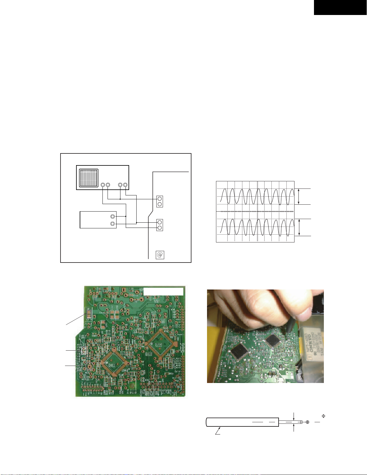
1. SERVO ADJUSTMENT
1-1. Preparation
Set the VR123 is center position.
Connect the cables to the test point. (Fig.-1)
1-2. Focus gain adjustment
Load the test disc (YEDS-18) on the tray and play the track 2.
Adjust R123 until 1kHz the waveform of channels 1 and 2 on
oscilloscope become specified level.
Check the jitter meter reading . It must be less than 12ns.
1-3. Remove the oscilloscope and audio oscillator.
Oscilloscope
CH 1 CH 2
GG
GG
+
++
NADG-7323
C-701A
(Fig.-2)
Wave form
P105
LD Short
Land
P104
R123
Focus Gain
Audio
Oscillator
+
GG
(Fig.-1)
Adjustment points
VC
P105
(RF)
FE2
P104
FE1
R123
NADG-7323
CH1
CH2
A
A:B=1:1.25
B
(Fig-2)
The driver for adjustment when adjusting is using the driver
for adjustment insulated so that it may not be effected of a hand.
Adjustment driver
The quality of the material insulated
Less than 1.4
Page 20

PACKING VIEW/ PARTS LIST
C-701A(S)
C-701A(
S)
P45
P61
C-701A
P83
P84
P85
P86
P87
P46
P41
P44
C-701A(S)
P71
C-701A(
S)
P48
P81
P82
P41
P73
PARTS LIST
REF. NO. PART NO. DESCRIPTION
P41
P44
P45
P46
P48
P61
P71
P73
P81 2010376 or Audio connection cable
29092023A Pad assy
29100123C Poly bag, 430 x 550
29110149 Cellophane tape
29110098 PP tape
29095906 Sheet
29100097-1A Poly bag, 350 x 250
29053835 Carton box
<MPP,MDT,MGT>
29053836 Carton box <MGR>
29362981A EAN label
2010396
REF. NO. PART NO. DESCRIPTION
P82 2010375 or RI cable
2010397
P83 29343190 Instruction manual, E
P84 29343191 Instruction manual, U3FSI <MPP>
P85 29343192 Instruction manual, U3GDSW <MPP>
P86 29343193 Instruction manual, CT
<MDT,MGR,MGT>
P87 29343203 Instruction manual, CS <MGR>
<MPP>: European model only
<MDT>: Taiwanese model only
<MGT>: Asian model only
<MGR>: Chinese model only
Page 21

C-701A
ONKYO CORPORATION
Sales & Product Planning Div. : 2-1, Nisshin-cho, Neyagawa-shi, OSAKA 572-8540, JAPAN
Tel: 072-831-8111 Fax: 072-833-5222
ONKYO U.S.A. CORPORATION
18 Park Way, Upper Saddle River, N.J. 07458, U.S.A.
Tel: 201-785-2600 Fax: 201-785-2650 E-mail: onkyo@onkyousa.com
ONKYO EUROPE ELECTRONICS GmbH
Industriestrasse 20, 82110 Germering, GERMANY
Tel: 089-849-320 Fax: 089-849-3265 E-mail: info@onkyo.de
ONKYO CHINA LIMITED
Units 2102-2107, Metroplaza Tower I, 223 Hing Fong Road, Kwai Chung,
N.T., HONG KONG Tel: 852-2429-3118 Fax: 852-2428-9039
HOMEPAGE
http://www.onkyo.co.jp/
 Loading...