

Omron ZG-RPD, ZG-RPD11, ZG-RPD41 Instruction Sheet
形
ZG-RPD□□
スマートセン サ
リア ルタイム パ ラレル 出 力 ユ ニット
取扱説明書
このたびは 、本製品をお買い上げいただきまして、まことにありがとうござ い
ます。ご使用に際しては、次の内容をお守りください 。
・電気の知識を有する専門家が扱ってください 。
・この取扱説明書をよくお読みになり、十分にご理解のうえ、正しくご使用
ください 。
・この取扱説明書はいつでも参照できるように大切に保管ください 。
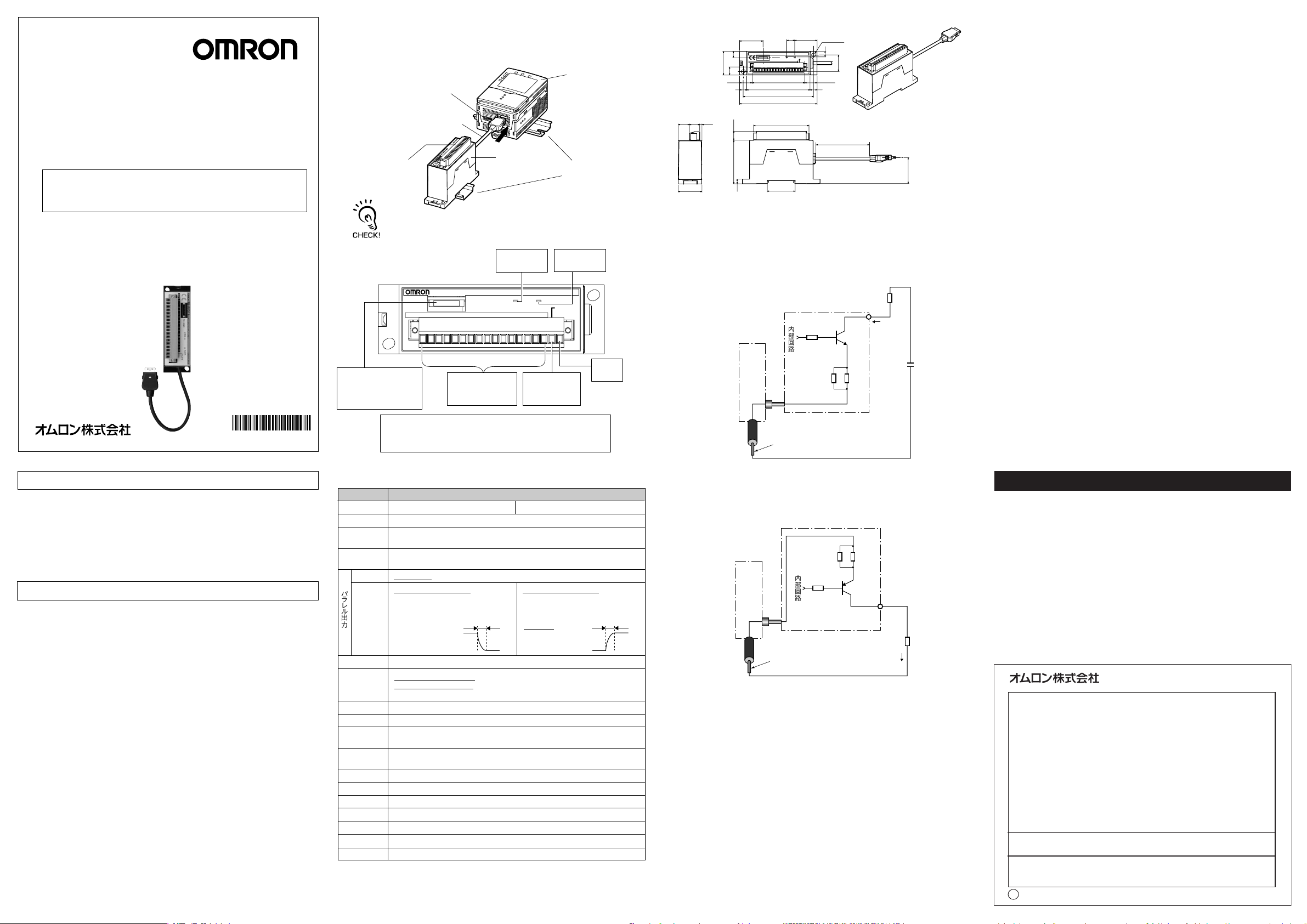
■システム構成
リアルタイムパラレル 出 力 ユニットは、形 ZG-RPD□□対応コントローラの RS-232C
コネクタに接 続して 使 用します 。
形 ZG-RPD□□対応コントローラの計測結果を、16bit バイナリデータ(2の補数)
に変換して出力します。
形ZG-RPD□□対応コントローラの
RS-232Cコネクタに接続
接続コネクタ
18極端子台
(着脱可能)
形ZG-RPD□□対応のコントローラ以 外 に 接 続しな い でください 。形ZG-RPD
□□対応コントローラ以 外 に 接 続 すると動 作しません。また 、故障の原因になりま
す。
■端子台配列(PINアサイン)
PARALLEL OUTPUT UNIT
ZG-RPD
RS-232C
DATA0123456789101112131415
形ZG-RPD□□
ERR表示灯
(点灯色:赤)
MADE IN JAPAN
形ZG-RPD□□対応
コントローラ
DINレール
PWR表示灯
(点灯色:緑)
PWRERR
GATE
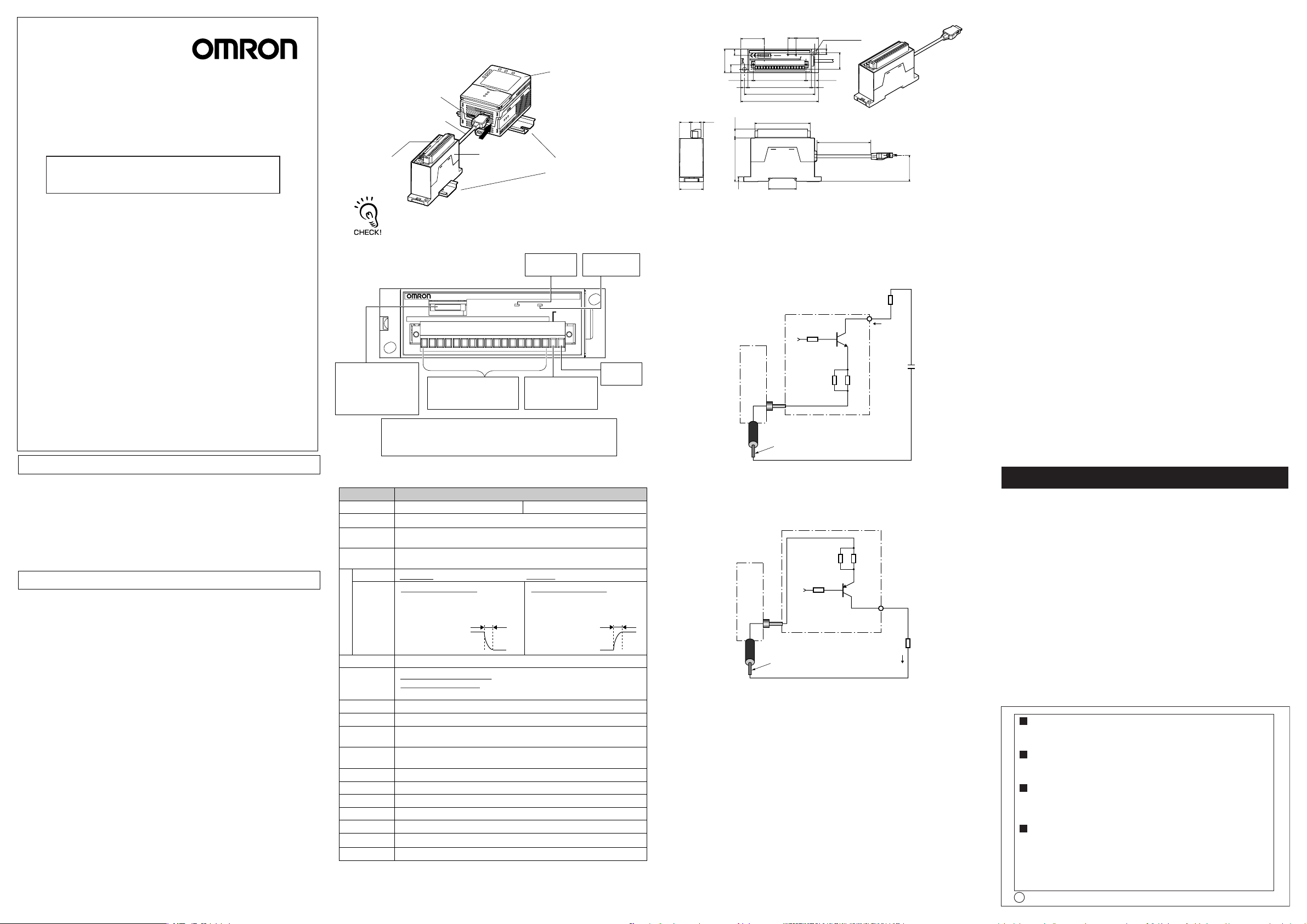
■外形寸法図
10
66.50
80
89
98
35.20
28.40
2−取付穴
7
21
15.65
9
70
(
150
),(2000)
(14.15) (2.85)
13
30
30
10.25
15.85
29.60
8
9
11.5
55
6
■出力回路図
(1)NPN出力タイプ(形ZG-RPD11)
データ出 力(D0-D15)およびGATE信号の計17出力すべてに
ついて、以下の回路構成を採用しています。
形ZG-RPD11
形ZG-RPD□□対応
コントローラ
内部回路
32.90
単位:(mm)
負荷
20mA(max.)
OMRON Corporation 2006 All Rights Reserved.
©
*9975150- 3C*
安全上の要点
以下に示すような項目は安全を確保する上で必要なことです の で 、必ず守ってください 。
1. 引火性、爆発性ガスの環境では使用しないでください 。
2. この製品は分解したり、修理、改造をしない でください 。
3. ロック機構のあるもの は必 ずロックしていることを 確 認して からご使用ください 。
4. 定格電圧を超える電圧や交流電源を使用しないでください 。
5. 負荷は定格以下でご使用ください 。
6. 廃棄するときは 、産業廃棄物として処 理してください 。
7. 原子力や人命に関わる装置などの安全回路には使用しないでください 。
使用上の注意
製品が動作不能、誤動作、または 性 能・機器への悪影響を防ぐため、以下の事を
守ってください 。
1. 下記の設置場所では使用しないでください 。
・ 直射日光のあたる場所や暖房器具のそば
・ 湿度が高く結露する恐れのある場所
・ 湿度変化が急激な場所
・ 凍結するような寒冷な場所
・ 腐食および可燃性ガスが発生する場所
・ 本体に直接振動や衝撃が加わる場所
・ ホコリや金属粉などがたまる場所
・ 有機溶剤や水、油などが本体にかかる場所
・ 強磁界、強電界の場所
・ 強い外乱光(レーザ光、アーク溶接光など)や強い電磁波が発生している場所
2. 電源および配線について
・ 本製品は形ZG-RPD□□対応コントローラ専用品です。形ZG-RPD□□対応
コントローラのRS-232Cコネクタに接 続して使 用してください 。
・ 形ZG-RPD□□対応コントローラ以外に接続すると動 作しません。また 、故障の
原因になります 。
・ 負荷用電源の逆接続および交流電源への接続はしないでください 。
・オープンコレクタ出力 は 、負荷を短絡させないでください 。
・ 高圧線、動力線と当製品の配線は別配線としてください 。同一配線あるいは同
一ダクトにすると誘 導を受 け、誤動作あるいは破損の原因になることがあります。
・市販のスイッチングレギュレータを使用する場合は、FG(フレームグランド)端子を
接地してください 。
・電源ラインにサージがある場合、使 用 環 境 に 応じてサージアブソーバを 接 続しご
使用ください 。
・ 周辺機器の着脱は、必 ず電源を切った状態で行ってください 。電源ONのまま行
うと故障の原因になります 。
RS-232Cコネクタ。形ZG
-RPD□□対応コントロー
ラのRS-232Cポートと 同
様に使用可能。
1PIN〜16PIN
パラレル 出 力
信号名:D0〜D15
【使用コネクタ形式】
・形ZG-RPD本体側⇒形SL3.5/18/90F-ORG(Weidmuller製)
・ケーブル接続側⇒ 形BL3.5/18F-ORG(Weidmuller製)
■定格/性能
項目 詳細
形ZG-RPD11(NPN出力タイプ)製品形式
データ出 力方式
データ
フォーマット
同期信号
信号名
パ
回路仕様
ラ
レ
ル
出力
状態表示灯
回路内電源電圧
絶縁抵抗
耐電圧
16bitパラレルオープンコレクタ出力
計測値データを、16bitバイナリデータ(2の補数)に変換し出力(信号名:D0〜D15)
データ確定タイミングを通知する同期信号(信号名:GATE)。
1bitオープンコレクタ出力
・バイナリ出力 信号名:D0〜D15(計16bit)・ゲート出力 信 号 名:GATE(計1bit)
・NPNオープンコレクタ出力
DC30Vmax.、20mAmax.、
残留電圧1.2V以下、
OFF→ON変化時ディレイ時 間:0.5μs
未満(24V、20mA時)
1ポート、最大115200bpsRS-232C
・PWR表示灯(点灯色:緑色)→形ZG-RPDが通電状態である場合に点灯する
・ERR表示灯(点灯色:赤色)→オープンコレクタ出力(データ出力:16bit、GATE:1bit)
の1bit以上に20mA以上の過電流が流れた場合、点灯する。
DC24VおよびDC3.3V。ただし、形ZG-RPD□□対応コントローラより、専用コネクタ経由で供給する。
0.5A以下消費電流
形ZG.-RPD□□対応コントローラに接続した状態で、形ZG-RPD□□対応コントローラ
のリード線一括とコントローラケ ース 間:20MΩ(250Vメガにて)
形ZG-RPD□□対応コントローラに接続した状態で、形ZG-RPD□□対応コントローラ
のリード線一括とコントローラケ ース 間:AC1000V50/60Hz1min
10〜150Hz(複振幅0.7mm)、X/Y/Z各方向 80min振動(耐久)
300m/s2 6方向 各3回(上下、左右、前後) 衝撃(耐久)
動作時0〜+50℃、保存時ー15〜60℃(ただし氷結、結露なきこと)周囲温度
動作時・保存時共に35〜85%RH(ただし、結露なきこと)周囲湿度
筐体:ABS材質
0.15m 、2mコード長
約130g(梱包材、付属品含まず)質量
17PIN
ゲート信号
信号名:GATE
形ZG−RPD41(PNP出力タイプ)
・PNPオープンコレクタ出力
20mAmax.、残留電圧1.2V以下、
OFF→ON変化時ディレイ時 間:0.5μs
未満(20mA時)
delay
18PIN
未使用
delay
15Ω
0V(
対応コントローラ
と内部で共通)
対応コントローラのGND線(ケーブル色:青)
5.1Ω
(2)PNP出力タイプ(形ZG−RPD41)
データ出 力(D0-D15)およびGATE信号の計17出力すべてに
ついて、以下の回路構成を採用しています。
形ZG-RPD□□対応
コントローラ
対応コントローラのGND(0V)線
(ケーブル色:青)
形ZG-RPD41
内部回路
DC24V
(対応コントローラと内部で共通)
15Ω
DC24V
5.1Ω
DC24V
負荷
20mA(max.)
ご使用に際してのご承諾事項
①安全を確保する目的で直接的または間接的に人体を検出する用途に、本製品を使用し
ないでください 。同用途には、当社センサカタログに掲載している安全センサをご使用く
ださい 。
②下記用途に使用される場合、当社営業担当者までご相談のうえ仕様書などによりご確
認いただくとともに、定格・性能に対し余裕を持った使い方や、万一故障があっても危険
を最小にする安全回路などの安全対策を講じてください 。
a)屋外の用途、潜在的な化学的汚染あるいは電気的妨害を被る用途
またはカタログ 、取扱説明書等に記載のない条件や環境での使用
b)原子力制御設備、焼却設備、鉄道・航空・車両設備、医用機械、娯楽機械、
安全装置、および行政機関や個別業界の規制に従う設備
c)人命や財産に危険が及びうるシ ステ ム・機械・装置
d)ガス、水道、電気の供給システムや24時間連続運転システムなどの
高い信頼性が必要な設備
e)その他、上記a)〜d)に準ずる、高度な安全性が必要とされる用 途
*上記は適合用途の条件の一部です。当社のベスト、総合カタログ・データシート等最新版
のカタログ、マニュアルに記載の保証・免責事項の内容をよく読 ん でご 使 用ください 。
●お問い合わせ先
カスタマサポートセンタ
フリー コ ー ル
携帯電話・PHSなどではご利用いただけませんので、その場合は下記電話番号へおかけください 。
電話055-982-5015(通話料がかかります )
〔技術のお問い合わせ時間〕
■
営業時間:8:00〜21:00
■営 業 日:365日
■上記フリ−コ−ル以外のセンシング機器の技術窓口:
電話055-982-5002(通話料がかかります )
〔営業のお問い合わせ時間〕
■
営業時間:9:00〜12:00/13:00〜17:30(土・日・祝祭日は休業)
■営 業 日:土・日・祝祭日/春期・夏期・年末年始休暇を除く
●FAXによるお問い合わせは下記をご利用ください 。
カスタマサポートセンタ お客様相談室 FAX055-982-5051
●その他のお問い合わせ先
納期・価格・修理・サンプ ル・仕様書は貴社のお取引先、
または貴社担当オムロン営業員にご相談ください 。
q
2009年10月
インダ ストリア ルオートメーションビジネスカンパニー
0120-919-066
Model
ZG-RPD□□
Smart Sensors
Real-time Parallel Output Unit
INSTRUCTION SHEET
Thank you for selecting OMRON product. This sheet primarily describes precautions required in installing and
operating the product.
Before operating the product, read the sheet thoroughly to
acquire sufficient knowledge of the product. For your convenience, keep the sheet at your disposal.
TRACEABILITY INFORMATION:
Representative in EU:
Omron Europe B.V.
Wegalaan 67-69
2132 JD Hoofddorp,
The Netherlands
The following notice applies only to products that carry the CE mark:
Notice:
This is a class A product. In residential areas it may cause radio
interference, in which case the user may be required to take adequate
measures to reduce interference.
OMRON Corporation
©
Precautions for Safe Use
Please observe the following precautions for safe use of the product:
1. Do not use the product in environments where it can be exposed to
inflammable/explosive gas.
2. Do not disassemble, repair or modify this product.
3. Be sure to make sure that locking mechanisms are locked before use.
4. The supply voltage must be within the rated range.
5. Use the power supply within the rated load.
6. Dispose of this product as industrial waste.
Please do not use ZG for the safety circuit such as devices related to nuclear power and life.
7.
Precautions for Correct Use
Please observe the following precautions to prevent failure to operate,malfunctions,
or undesirable effects on product performance.
1. Do not install the product in locations subjected to the following conditions:
・Direct sunlight or near heaters
・Condensation caused by high humidity
・Sudden changes in humidity
・Cold conditions that may cause freezing
・Presence of corrosive or flammable gases
・Direct vibration or shock
・Build-up of dust or metal chips
・Spraying by organic solvents, water, oil or other liquids
・Strong magnetic or electric field
・Reflection of intense light (such as other laser beams or electric arc-welding
machines) or generation of strong electromagnetic waves
2. Power Supply and Wiring
・This product is exclusively for the controller corresponding to ZG-RPD. Connect
it to the RS-232C connector of the controller corresponding to ZG-RPD for use.
・This product will not function or will break down if it is connected to a device
other than the controller corresponding to ZG-RPD.
・Do not reverse connect the power supply for the load or connect to an AC power supply.
・Open-collector outputs should not be short-circuited.
・High-voltage lines and power lines must be wired separately from this product.
Wiring them together or placing them in the same duct may cause induction,
resulting in malfunction or damage.
・When using a commercially available switching regulator, make sure that the FG
(Frame Ground) terminal is grounded.
・If surge currents are present in the power lines, connect surge absorbers that suit
the operating environment.
・Before connecting/disconnecting peripheral devices, make sure that the Data
Storage Unit is turned OFF. The Data Storage Unit may break down if it is
connected or disconnected while the power is ON.
Manufacturer:
Omron Corporation,
Shiokoji Horikawa, Shimogyo-ku,
Kyoto 600-8530 JAPAN
Ayabe Factory
3-2 Narutani, Nakayama-cho,
Ayabe-shi, Kyoto 623-0105 JAPAN
All Rights Reserved.
2006
■System Configuration
Connect the Real-time Parallel Output Unit to the RS-232C connector of the
controller corresponding to ZG-RPD for use.
The measurements results of the controller corresponding to ZG-RPD are converted
to 16-bit binary data(two’s complement) before they are output.
Connect to the RS-232C
connector of
the controller
corresponding to ZG-RPD.
The controller
corresponding to
ZG-RPD
Connector
18-pole
terminal block
ZG-RPD□□
DIN track
(detachable)
The ZG-RPD□□ is exclusively for the controller corresponding to ZG-RPD.
Do not connect to a device other than the controller corresponding to ZG-RPD.
The ZG-RPD□□ will not function or will break down if it is connected to a
device other than the controller corresponding to ZG-RPD.
■Terminal Block Pin Assignments
PARALLEL OUTPUT UNIT
ZG-RPD
RS-232C
DATA0123456789101112131415
RS-232C connector.
Can be used in the same
way as the RS-232C port
on the controller
corresponding to ZG-RPD.
Pin Nos.1 to 16
Parallel output
Signal names: D0 to D15
ERR indicator
(lit color: red)
MADE IN JAPAN
PWRERR
Pin No.17
Gate signal
Signal name: GATE
PWR indicator
(lit color: green)
GATE
Pin No.18
not used
[Type of Connectors Used]
・ZG-RPD body side ⇒ SL 3.5/18/90F-ORG (made by Weidmuller)
・Cable connection side ⇒ BL 3.5/18F-ORG (made by Weidmuller)
■Specifications
Item Details
Data output system
Data format
Synchronization
signal
Signal name
Circuit
specifications
Parallel output
Status
indicators
Circuit internal
power supply voltage
Current
consumption
Insulation
resistance
Dielectric
strength
Vibration resistance
(destructive)
Shock resistance
(destructive)
Ambient
temperature
Ambient humidity
ZG-RPD11 (NPN output type)Model
16-bit parallel open collector output
Measurement value data is converted to 16-bit binary data(two’s complement) before output.
(signal names: D0 to D15)
Synchronization signal for notifying data determination timing
(signal name: GATE)1-bit open collector output
・
Binary output: signal name: D0 to D15 (total 16 bits),
・NPN open collector output
30 VDC max., 20 mA max.,
residual voltage 1.2 V or less,
delay time at OFF → ON change:
less than 0.5μs
(at 24 V, 20 mA)
1 port, max. 115,200 bpsRS-232C
・PWR indicator (lit color: green) → Lights when ZG-RPD is energized.
ERR indicator (lit color: red) → Lights when an energizing current of 20 mA or more
・
flows to 1 bit or more of the open collector output (data output: 16 bits, GATE: 1 bit)
24 VDC and 3.3 VDC. Power supplied from the controller corresponding to ZG-RPD via exclusive connector.
0.5 A or less.
Connected to the controller corresponding to ZG-RPD, across all lead wires and controller
case of the controller corresponding to ZG-RPD: 20 MΩ (by 250 V megger)
Connected to the controller corresponding to ZG-RPD, across all lead wires and controller
case of the controller corresponding to ZG-RPD: 1000 VAC, 50/60 Hz, 1 min
10 to 150 Hz 0.7-mm double amplitude, 80 min each in X, Y and Z directions
300 m/s2 3 times each in six directions (up/down, left/right, forward/backward)
Operating: 0 to 50 ℃, Storage: -15 to +60 ℃ (with no icing or condensation)
Operating/storage: 35 to 85% RH (with no condensation)
Case: ABSMaterials
0.15m, 2mCable length
Approx. 130 g (excluding packing materials and accessories)Weight
ZG-RPD41 (PNP output type)
・
Gate output: signal name: GATE (total 16 bits)
・PNP open collector output
20 mA max.,
residual voltage 1.2 V or less,
delay time at OFF → ON change:
less than 0.5
(at 20 mA)
delay
μs
delay
■Dimensions
10
66.50
35.20
28.40
2-mounting hole
7
21
80
89
98
70
15.65
9
(
150
), (2000)
(14.15) (2.85)
13
30
29.60
8
30
10.25
15.85
9
11.5
55
6
■Output Circuit Diagrams
(1) NPN output type (ZG-RPD11)
The following circuit configuration is used for all 17 outputs
(data outputs (D0 to D15) and GATE signal).
ZG-RPD11
The controller
corresponding to ZG-RPD
Internal circuit
15Ω
0 V (shared internally
with the controller
corresponding to ZS-RPD)
The controller corresponding to ZG-RPD
GND lead (cable color: blue)
(2) PNP output type (ZG-RPD41)
The following circuit configuration is used for all 17 outputs
(data outputs (D0 to D15) and GATE signal).
ZG-RPD41
The controller
corresponding to ZG-RPD
Internal circuit
24 VDC (shared internally
with the controller corresponding
to ZG-RPD)
The controller corresponding
to ZG-RPD GND (0 V) lead
(cable color: blue)
15Ω
5.1Ω
DC24V
5.1Ω
Load
20mA(max.)
DC24V
Load
20mA(max.)
32.90
(unit: mm)
Suitability for Use
THE PRODUCTS CONTAINED IN THIS SHEET ARE NOT SAFETY RATED.
THEY ARE NOT DESIGNED OR RATED FOR ENSURING SAFETY OF
PERSONS, AND SHOULD NOT BE RELIED UPON AS A SAFETY
COMPONENT OR PROTECTIVE DEVICE FOR SUCH PURPOSES.
Please refer to separate catalogs for OMRON's safety rated products.
OMRON shall not be responsible for conformity with any standards, codes, or
regulations that apply to the combination of the products in the customer's
application or use of the product.
Take all necessary steps to determine the suitability of the product for the
systems, machines, and equipment with which it will be used.
Know and observe all prohibitions of use applicable to this product.
NEVER USE THE PRODUCTS FOR AN APPLICATION INVOLVING
SERIOUS RISK TO LIFE OR PROPERTY WITHOUT ENSURING THAT THE
SYSTEM AS A WHOLE HAS BEEN DESIGNED TO ADDRESS THE RISKS,
AND THAT THE OMRON PRODUCT IS PROPERLY RATED AND
INSTALLED FOR THE INTENDED USE WITHIN THE OVERALL
EQUIPMENT OR SYSTEM.
See also Product catalog for Warranty and Limitation of Liability.
EUROPE
OMRON EUROPE B.V. Sensor Business Unit
Carl-Benz Str.4, D-71154 Nufringen Germany
Phone:49-7032-811-0 Fax: 49-7032-811-199
NORTH AMERICA
OMRON ELECTRONICS LLC
One Commerce Drive Schaumburg,IL 60173-5302 U.S.A.
Phone:1-847-843-7900 Fax : 1-847-843-7787
ASIA-PACIFIC
OMRON ASIA PACIFIC PTE. LTD.
No. 438A Alexandra Road #05-05-08(Lobby 2),
Alexandra Technopark, Singapore 119967
Phone : 65-6835-3011 Fax :65-6835-2711
CHINA
OMRON(CHINA) CO., LTD.
Room 2211, Bank of China Tower,
200 Yin Cheng Zhong Road,
PuDong New Area, Shanghai, 200120, China
Phone : 86-21-5037-2222 Fax :86-21-5037-2200
OMRON Corporation
o
OCT, 2009
 Loading...