

Omron ZG2-WDC11, ZG2-WDC11A, ZG2-WDC41, ZG2-WDC41A Instruction Sheet
Model
ZG2-WDC□□
Smart Sensor
Sensor Controller
for ZG2-WDS□□□
INSTRUCTION SHEET
Thank you for selecting OMRON product. This sheet primarily describes
precautions required in installing and operating the product.
Before operating the product, read the sheet thoroughly to acquire
sufficient knowledge of the product. For your convenience, keep the
sheet at your disposal.
TRACEABILITY INFORMATION:
Importer in EU:
OMRON Europe B.V.
Wegalaan 67-69,
NL-2132 JD Hoofddorp
The Netherlands
The following notice applies only to products that carry the CE mark:
Notice:
This is a class A product. In residential areas it may cause radio
interference, in which case the user may be required to take adequate
measures to reduce interference.
OMRON Corporation
©
PRECAUTIONS FOR SAFE USE
Please observe the following precautions for safe use of the product:
1. Do not use the product in environments where it can be exposed to
inammable/explosive gas.
2. Do not disassemble, repair or modify this product.
3. Be sure to make sure that locking mechanisms are locked before use.
4. The supply voltage must be within the rated range.
5. Use the power supply within the rated load.
6. Dispose of this product as industrial waste.
PRECAUTIONS FOR CORRECT USE
1. Do not install the product in locations subjected to the following conditions:
・ Direct sunlight or near heaters
・ Condensation caused by high humidity
・ Sudden changes in humidity
・ Cold conditions that may cause freezing
・ Presence of corrosive or ammable gases
・ Direct vibration or shock
・ Build-up of dust or metal chips
・ Spraying by organic solvents, water, oil or other liquids
・ Strong magnetic or electric eld
・
Reection of intense light (such as other laser beams or electric arc-welding machines)
2. Power Supply and Wiring
・ Reverse connection of power supply is not allowed. Connection to AC power supply
is also not allowed.
・ Open-collector outputs should not be short-circuited.
・ Use the Extension Cable ZG2-XC□□CR: length 25m/15m/8m/3m for extending
the cable between the Sensor Head and Sensor Controller. The total length differs
according to the Extension cable.
・ High-voltage lines and power lines must be wired separately from this product.
Wiring them together or placing them in the same duct may cause induction,
resulting in malfunction or damage.
・ When using a commercially available switching regulator, make sure that the FG
(Frame Ground) terminal is grounded.
・ If surge currents are present in the power lines, connect surge absorbers that suit the
operating environment.
・ Before connecting/disconnecting the Sensor Head, make sure that the Sensor
Controller is turned OFF. The Sensor Controller may break down if it is connected
or disconnected while the power is ON.
・ Use only the specied combinations of Sensor Head and Sensor Controller.
Manufacturer:
OMRON Corporation,
Shiokoji Horikawa, Shimogyo-ku,
Kyoto. 600-8530 JAPAN
2016 All Rights Reserved.
9309251-6B
3. Orientation when Installing the Sensor Controller
To improve heat radiation, install the Sensor Controller only in the orientation show
below.
Correct
Do not install the Sensor Controller in the following orientations.
IncorrectIncorrect
4. Cleaning
・ Do not use paint thinner, benzene, acetone or kerosene to clean the Sensor
Controller. Doing so will melt the surface of the Sensor Controller.
・ Use commercially available alcohol.
■Communication with a Host Device
Before communicating with a host device, make sure that the product has started up.
Also, clear the receive buffers on the device in use or perform other measures since
undetermined signals might be output from the host interface when this product is
started up.
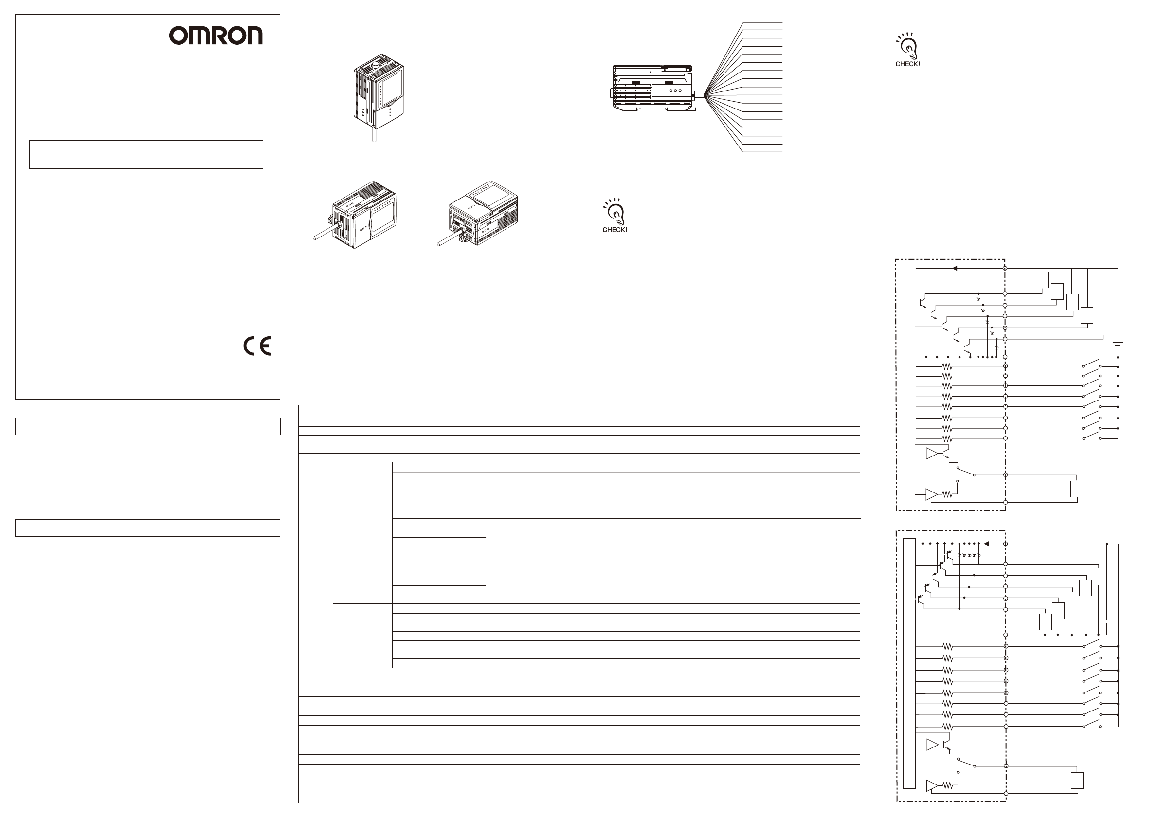
■Specifications
Item Model
Output method
No. of mounted Sensors
Measurement time
Unit of minimum display
Range of display
Display LCD monitor
LED monitor
Analog output
Output
Judgement output
(ALL-PASS/NG/ERROR)
External
I/F
Input
Trigger assistance output
(ENABLE/GATE)
Laser off input(LD-OFF)
Zero reset input(ZERO-RESET)
Trigger input (TRIG)
Bank setting input
(BANK A/BANK B/BANK C/BANK D)
Serial I/O
Functions
USB2.0
RS-232C
Bank selection
Sensitivity adjustment
Measurement items
Trigger mode
Power supply voltage
Current consumption
Dialectic strength
Ambient temperature
Ambient humidity
Degree of protection
Vibration resistance (destructive)
Shock resistance (destructive)
Materials
Cord length
Weight
Accessories
ZG2-WDC11/WDC11A
NPN
1 per Sensor Controller
5ms/8ms/16ms
10nm
-999.99999~999.99999
TFT2.2-inch Color LCD (display dots:557×234pix)
・
Judgement result indicator (color:orange):T1/T2/T3/T4 ・Laser on indicator (color:green):LD ON
・
Zero reset indicator (color:green):ZERO-RESET ・Trigger indicator (color:green):TRIG
Selectable from 2types voltage/current output (selected by side switch on base)
・
At voltage output:-10 to +10V,output impedance:40Ω
・
At current output:4 to 20mA,max.load resistance:300Ω
NPN open-collector,30VDC,50mA max.,
Residual voltage:1.2V max.
ON:Short-circuited with 0V terminal or 1.5V max.
OFF:Open (leakage current:0.1mA max.)
1 port,FULL-SPEED[max.12Mbps],MINI-B
1 port,max. 115200bps
16banks per Sensor Controller
MULTI/HIGH SPEED MULTI/AUTO/FIXED
Height/2-point step/3-point step/Edge position/Edge width/Angle/Intersection angle/Intersection coordinates/
Cross-sectional area/Calculations between tasks (max. 8 items simultaneously selectable)
External trigger/Continuous
21.6V DC to 26.4V DC(including ripple)
0.8A max.
Across all lead wires and controller case,1000VAC,50/60Hz,1min
Operating:0 to 50℃,Storage:-15 to 60℃ (with no icing or condensation)
Operating and storage:35% to 85% RH (with no condensation)
IEC60529,IP20
Destruction:10 to 150Hz,0.35-mm single amplitude,10 times each X,Y,and Z directions for 8min
Destruction:150m/s ,3 times each 6 directions(up/down,left/right,forward/backward)
2
Case: Polycarbonate (PC), Cable sheath: heat-resistant PVC
2m
Approx.300g(including cord)
ZG2-WDC□1 : ferrite core (large) (1 p’ ce), Insure Lock (1 p’ ce), Instruction Sheet (This sheet)
ZG2-WDC□1A : ferrite core (large) (1 p’ ce), ferrite core (small) (2 p’ ces),
Insure Lock (1 p’ ce), Instruction Sheet (This sheet), Smart Monitor ZG2 (exclusive PC software, CD-ROM), USB cable
■External I/O
Brown
Blue
Red
Green
Black
Pink
Gray
Co-axial (black)
Shield
Yellow
Light blue
Yellow green
Yellow/Black
Purple
White
Orange
White/Black
(1) Power supply(24V)
(2) GND(0V)
(3) OUT0
(4) OUT1
(5) OUT2
(6) OUT3
(7) OUT4
(8) Analog output
(9) Analog GND
(10) IN0
(11) IN1
(12) IN2
(13) IN3
(14) IN4
(15) IN5
(16) IN6
(17) IN7
(1) Power supply
This connects the 24 V DC (±10%) power supply. When using a Sensor
Controller with a PNP output, the power supply terminal is also the common I/O
terminal for all I/O except for the Analog output.
・
Supply power from a DC power supply unit that has a countermeasure (safety
ultra-low voltage circuit) built-in for preventing high voltages from occurring.
・ Wire the power supply separately from other devices. Wiring them together
or placing them in the same duct may cause induction, resulting in
malfunction or damage.
(2) GND
The GND terminal is the 0V power supply terminal. When using a Sensor
Controller with an NPN output, the GND terminal is also the common I/O
terminal for all I/O except for the Analog output.
(3) OUT0 (ALL PASS output)
This outputs judgment results (ALL PASS).
(4) OUT1 (NG output)
This outputs judgment results (NG).
(5) OUT2 (ERROR output)
This turns on when an error is generated.
(6) OUT3 (ENABLE output)
This turns ON when the sensor is ready for TRIG input.
(7) OUT4 (GATE output)
This turns ON when the measurement data can be aquired.
(8) Analog output
The Analog output outputs a current or voltage in accordance with the measured value.
ZG2-WDC41/WDC41A
PNP
PNP open-collector,50mA max.,
Residual voltage:1.2V max.
ON:
Supply voltage short-circuited or within supply voltage -1.5V max.
OFF:Open (leakage current:0.1mA max.)
(9) Analog GND
The Analog GND terminal is the 0V terminal for the Analog output.
・This ground wire must be wired separately from the other ground
wires.
(10) IN0 (BANK A)
Bank switching input A.
(11) IN1 (BANK B)
Bank switching input B.
(12) IN2 (BANK C)
Bank switching input C.
(13) IN3 (BANK D)
Bank switching input D.
(14) IN4 (LD-OFF)
Laser ON/OFF switch input. If this signal is set on,the laser will stop emission.
(15) IN5 (ZERO-RESET)
Zero reset input.
(16) IN6 (TRIG)
External Trigger input.
(17) IN7 (HOLD-RESET)
Hold reset input.
■I/O circuit diagrams
・NPN type (ZG2-WDC11/WDC11A)
Brown
24 V DC
Load
Red
OUT0
OUT1
OUT2
OUT3
OUT4
GND (0V)
IN0
IN1
IN2
IN3
IN4
IN5
IN6
IN7
24 V DC
OUT0
OUT1
OUT2
OUT3
OUT4
Load
GND(0V)
IN0
IN1
IN2
IN3
IN4
IN5
IN6
IN7
Load
Analog output
Analog GND
Load
Analog output
Analog GND
Load
Load
Load
Current output: 300 Ω or lower
Load
Voltage output: 10 k
Load
Load
Load
Current output: 300 Ω or lower
Load
Voltage output: 10 kΩ or higher
24 V
DC
24 V DC
Ω
or higher
Internal circuit
Current output
40Ω
4 to 20mA
Voltage output
±10V
Current/voltage
output switch
・PNP type (ZG2-WDC41/WDC41A)
Internal circuit
Current output
40Ω
4 to 20mA
Voltage output
±10V
Current/voltage
output switch
Green
Black
Pink
Gray
Blue
Yellow
Light blue
Yellow green
Yellow/Black
Purple
White
Orange
White/Black
Co-axial (black)
Shield
Brown
Red
Green
Black
Pink
Gray
Blue
Yellow
Light blue
Yellow green
Yellow/Black
Purple
White
Orange
White/Black
Co-axial (black)
Shield
■Attaching the ferrite core
Attach the ferrite core (provided with the Sensor Controller) to the I/O cable of the
Sensor Controller.
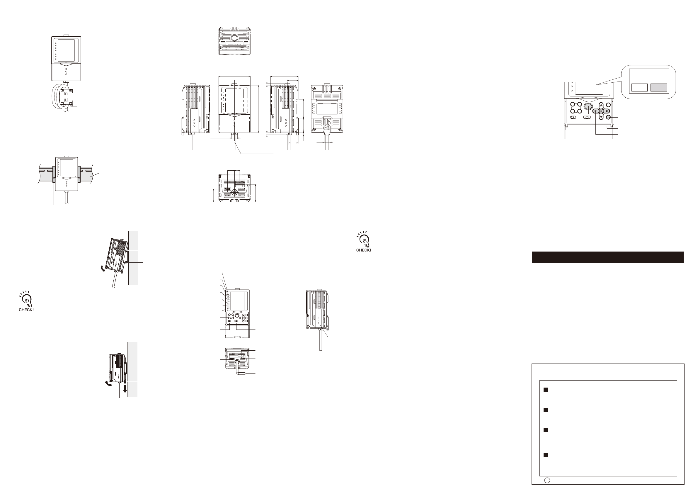
■Dimensions
(unit: mm)
(6)ZERO-RESET indicator
The ZERO-RESET indicator lights when the zero reset function is enabled.
(7) TRIG indicator
The TRIG indicator lights while inputting the trigger signal.
(8) Control keys
The Control keys are for setting measurement conditions and information.
■How to Switch the Display Language to English
Only when power supply rst time is turned on,The language switch menu is
automatically displayed.Please select[ENG(English)] or [JPN(Japanese)] with a right
and left key,and decide it with the SET key.
The content of the selection is reected when starting.
*If you want to start language selection menu since the second times,Please turn on
power while pushing the menu key.
Ferrite core
Insulation lock
*Please two turns and install the cable.
■Mounting
DIN track (sold separately)
PFP-100N (1 m)
PFP-50N (0.5 m)
PFP-100N2 (1 m)
End plate (sold separately)
PFP-M
■Installing the DIN track
The following describes how to attach the 35 mm wide DIN track by quick, easy operation.
① Hook the hook on the connector end
onto the DIN track.
Hook on connector
end
②
Push the Sensor Controller down onto
the DIN track until the hook on the I/O
Hook on I/O cable
end
cable side is locked.
Push down until you hear it snap into
place.
When Sensor Controllers are used gang-mounted, attach the End
Plate (sold separately PFP-M) on the DIN track beforehand.
Always hook the hook on the connector end on the DIN track rst.
Hooking the I/O cable end on the DIN track rst may impair the
mounting strength of the DIN track attachment.
■Removing the DIN track
The following describes how to remove the Sensor Controller from the DIN track.
① Pull the hook on the I/O cable end of
the Sensor Controller downwards.
60
11.7mmdia.
HEAT-RESISTANTPVCCORD
5.7DIA.,16CORES,
STANDARDLENGTH2M
10
13
24.2
■Part Names and Functions
(1)T1 indicator
(2)T2 indicator
(3)T3 indicator
(4)T4 indicator
(5)LD ON indicator
(6)ZERO-RESET indicator
(7)TRIG indicator
(8)Control keys
(17)USB port
52.5
3.34
90
3.9
32.9
(12)Sensor Head connector
(11)LCD monitor
(10)Mode selector switch(9)Menu selector switch
(14)RS-232C connector
(15)Voltage/current switch
20.8
18.4
(9) Menu selector switch
This switch selects the setup menu.
STD : Standard menu.Select this mode when setting the minimum require
items for measurement.
EXP : Expert menu.Select this mode when making a more detailed setup.
PLEASESELECT
LANGUAGE
ENG
JPN
(10) Mode selector switch
35.527.94.3
10.8
This switch selects the operating mode.
FUN : Select this mode when setting measurement conditions.
ADJ : Select this mode when adjusting the judgement threshold value.
RUN : Select this mode when performing measurement.
Output is performed only when the RUN mode is currently selected.
(11) LCD monitor
MENUkey
SETkey
RIGHTkey
LEFTkey
The LCD monitor displays setup menus and images captured from the sensor
head.
(12) Sensor Head connector
This connector connects the Sensor Head.
(13) Coupler
This coupler connects the Controller Unit when gang-mounting Sensor
Controllers.
(14) RS-232C connector
Connect the RS-232C cable when you are connecting the Sensor Controller to a
PLC or a personal computer.
(15) Voltage/current switch
The Voltage/Current switch selects between voltage output and current output.
Before operating this switch, make sure that the Sensor Controller is turned OFF.
Also, make sure that the load connected to "Analog output wire (co-axial)
- Analog GND wire" satises the rating (see I/O circuit diagram) of the set
• Notice for Korea Radio Law
A급 기기(업무용 방송통신기자재)
이 기기는 업무용(A급) 전자파적합기기로서 판매자
또는 사용자는 이 점을 주의하시기 바라며,가정외의
지역에서 사용하는 것을 목적으로 합니다.
state (voltage or current output) before turning the Sensor Controller ON.
Otherwise, the Sensor Controller may be damaged.
(16) I/O cable
The I/O cable connects the Sensor Controller to the power supply and external
devices, such as sync sensors or programmable controllers.
(17) USB port
Connect the USB cable to the USB port to connect to a personal computer.
Omron Companies shall not be responsible for conformity with any standards,
codes or regulations which apply to the combination of the Product in the
Buyer’s application or use of the Product. At Buyer’s request, Omron will
provide applicable third party certification documents identifying ratings and
limitations of use which apply to the Product. This information by itself is not
sufficient for a complete determination of the suitability of the Product in
Suitability for Use
combination with the end product, machine, system, or other application or
use. Buyer shall be solely responsible for determining appropriateness of the
particular Product with respect to Buyer’s application, product or system.
Buyer shall take application responsibility in all cases.
NEVER USE THE PRODUCT FOR AN APPLICATION INVOLVING
SERIOUS RISK TO LIFE OR PROPERTY WITHOUT ENSURING THAT THE
(13)Coupler
SYSTEM AS A WHOLE HAS BEEN DESIGNED TO ADDRESS THE RISKS,
AND THAT THE OMRON PRODUCT(S) IS PROPERLY RATED AND
INSTALLED FOR THE INTENDED USE WITHIN THE OVERALL
EQUIPMENT OR SYSTEM.
See also Product catalog for Warranty and Limitation of Liability.
② Lift up the Sensor Controller from the
I/O cable, and remove it from the DIN
track.
Hook on I/O cable
end
(16)I/O cable
(1) T1 indicator
The T1 indicator lights When the judgement result of TASK1/TASK5 is [OK].
(2) T2 indicator
The T2 indicator lights When the judgement result of TASK2/TASK6 is [OK].
(3) T3 indicator
The T3 indicator lights When the judgement result of TASK3/TASK7 is [OK].
(4) T4 indicator
The T4 indicator lights When the judgement result of TASK4/TASK8 is [OK].
(5) LD ON indicator
The LD ON indicator lights while the Sensor Head is emitting a laser beam.
OMRON Corporation
Tokyo, JAPAN
Regional Headquarters
OMRON EUROPE B.V.
Sensor Business Unit
Carl-Benz-Str. 4, D-71154 Nufringen, Germany
Tel: (49) 7032-811-0/Fax: (49) 7032-811-199
OMRON ELECTRONICS LLC
2895 Greenspoint Parkway, Suite 200
Hoffman Estates, IL 60169 U.S.A.
Tel: (1) 847-843-7900/Fax: (1) 847-843-7787
OMRON ASIA PACIFIC PTE. LTD.
No. 438A Alexandra Road # 05-05/08 (Lobby 2),
Alexandra Technopark,
Singapore 119967
Tel: (65) 6835-3011/Fax: (65) 6835-2711
OMRON (CHINA) CO., LTD.
Room 2211, Bank of China Tower,
200 Yin Cheng Zhong Road,
PuDong New Area, Shanghai, 200120, China
Tel: (86) 21-5037-2222/Fax: (86) 21-5037-2200
s
Oct, 2014
D
Industrial Automation Company
Contact: www.ia.omron.com
 Loading...