

Omron ZFX BROCHURE

Cat. No. Z01E-EN-01
Smart Sensor
ZFX
Vision Sensor with built-in
touch screen
SHORT MANUAL

ZFX
Vision Sensor
with built-in touch screen
Short Manual
Ver. 1.0, January 2008


TABLE OF CONTENTS
SECTION 1
Preparation . . . . . . . . . . . . . . . . . . . . . . . . . . . . . . . . . . . . . . . 5
1-1 System Overview. . . . . . . . . . . . . . . . . . . . . . . . . . . . . . . . . . . . . . . . . . . . . . . . . . . . . . . . . . 5
1-2 Connecting the Devices . . . . . . . . . . . . . . . . . . . . . . . . . . . . . . . . . . . . . . . . . . . . . . . . . . . . . 6
1-3 Installing the Controller. . . . . . . . . . . . . . . . . . . . . . . . . . . . . . . . . . . . . . . . . . . . . . . . . . . . . 8
1-4 Installing the Intelligent Cameras . . . . . . . . . . . . . . . . . . . . . . . . . . . . . . . . . . . . . . . . . . . . . 10
1-5 Installing the C-mount Cameras . . . . . . . . . . . . . . . . . . . . . . . . . . . . . . . . . . . . . . . . . . . . . . 12
1-6 Installing the External Lightings (Only For ZFX-SC50/SC90) . . . . . . . . . . . . . . . . . . . . . . 14
1-7 Installing the External Lightings (Only For C-mount Camera (ZFX-S/SC)) . . . . . . . . . . . . 15
SECTION 2
Main Operation. . . . . . . . . . . . . . . . . . . . . . . . . . . . . . . . . . . . 17
2-1 Operation Mode. . . . . . . . . . . . . . . . . . . . . . . . . . . . . . . . . . . . . . . . . . . . . . . . . . . . . . . . . . . 17
2-2 Adjusting the brightness of image . . . . . . . . . . . . . . . . . . . . . . . . . . . . . . . . . . . . . . . . . . . . . 18
2-3 Measurement Setting Example (Pattern Search) . . . . . . . . . . . . . . . . . . . . . . . . . . . . . . . . . . 20
2-4 Position Correction . . . . . . . . . . . . . . . . . . . . . . . . . . . . . . . . . . . . . . . . . . . . . . . . . . . . . . . . 22
2-5 Getting the clear image . . . . . . . . . . . . . . . . . . . . . . . . . . . . . . . . . . . . . . . . . . . . . . . . . . . . . 24
2-6 Changing the Display Information (ADJ/RUN Mode) . . . . . . . . . . . . . . . . . . . . . . . . . . . . . 30
2-7 Re-measuring the saved image (ADJ Mode). . . . . . . . . . . . . . . . . . . . . . . . . . . . . . . . . . . . . 31
SECTION 3
Run-Mode Measurement Process . . . . . . . . . . . . . . . . . . . . . 33
SECTION 4
Item Overview . . . . . . . . . . . . . . . . . . . . . . . . . . . . . . . . . . . . . 41
4-1 ITEM Overview (Pattern Search) . . . . . . . . . . . . . . . . . . . . . . . . . . . . . . . . . . . . . . . . . . . . . 41
4-2 ITEM Overview (Sensitive Search). . . . . . . . . . . . . . . . . . . . . . . . . . . . . . . . . . . . . . . . . . . . 43
4-3 ITEM Overview (Flexible Search) . . . . . . . . . . . . . . . . . . . . . . . . . . . . . . . . . . . . . . . . . . . . 44
4-4 ITEM Overview (Graphic Search) . . . . . . . . . . . . . . . . . . . . . . . . . . . . . . . . . . . . . . . . . . . . 45
4-5 ITEM overview (Area) . . . . . . . . . . . . . . . . . . . . . . . . . . . . . . . . . . . . . . . . . . . . . . . . . . . . .46
4-6 ITEM Overview (Labeling). . . . . . . . . . . . . . . . . . . . . . . . . . . . . . . . . . . . . . . . . . . . . . . . . . 47
4-7 ITEM Overview (Position) . . . . . . . . . . . . . . . . . . . . . . . . . . . . . . . . . . . . . . . . . . . . . . . . . . 49
4-8 ITEM Overview (Width) . . . . . . . . . . . . . . . . . . . . . . . . . . . . . . . . . . . . . . . . . . . . . . . . . . . . 51
4-9 ITEM Overview (Count) . . . . . . . . . . . . . . . . . . . . . . . . . . . . . . . . . . . . . . . . . . . . . . . . . . . . 52
4-10 ITEM Overview (Angle) . . . . . . . . . . . . . . . . . . . . . . . . . . . . . . . . . . . . . . . . . . . . . . . . . . . .53
4-11 ITEM Overview (Bright). . . . . . . . . . . . . . . . . . . . . . . . . . . . . . . . . . . . . . . . . . . . . . . . . . . .54
4-12 ITEM Overview (HUE). . . . . . . . . . . . . . . . . . . . . . . . . . . . . . . . . . . . . . . . . . . . . . . . . . . . .55
4-13 ITEM Overview (Defect) . . . . . . . . . . . . . . . . . . . . . . . . . . . . . . . . . . . . . . . . . . . . . . . . . . .56
4-14 ITEM Overview (Grouping) . . . . . . . . . . . . . . . . . . . . . . . . . . . . . . . . . . . . . . . . . . . . . . . . . 58
3

SECTION 5
Appendices. . . . . . . . . . . . . . . . . . . . . . . . . . . . . . . . . . . . . . . . 59
5-1 What is decided by AUTO setting. . . . . . . . . . . . . . . . . . . . . . . . . . . . . . . . . . . . . . . . . . . . . 59
5-2 BANK and BANK-Group . . . . . . . . . . . . . . . . . . . . . . . . . . . . . . . . . . . . . . . . . . . . . . . . . . . 60
Revision History . . . . . . . . . . . . . . . . . . . . . . . . . . . . . . . . . . . 62
4
1-1 System Overview
3 42
1
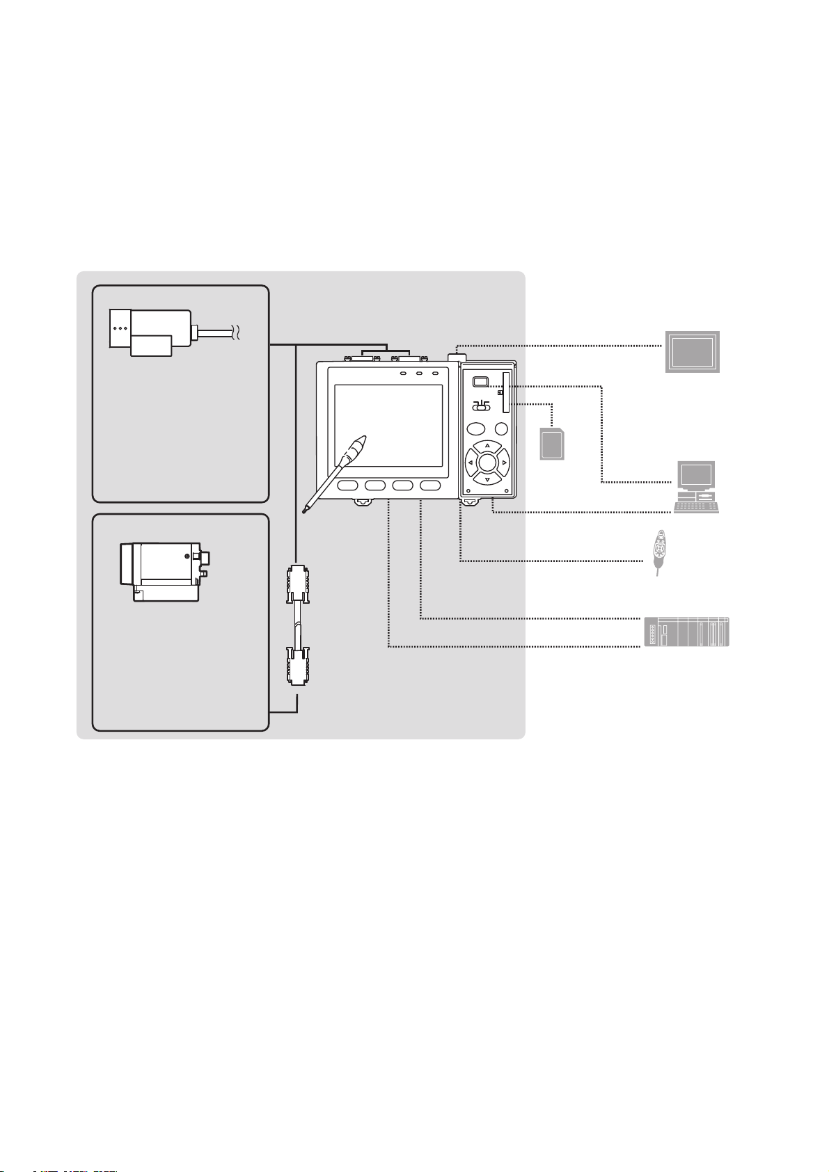
Basically, the ZFX-C is configured by the Controller and the camera.
Other external devices can be selected to be used in combination with the
ZFX-C according to the user’s specific requirements.
Cameras with lighting
(cable built-in)
- Color camera
ZFX-SC10/SC50/SC50W
ZFX-SC90/SC90W
ZFX-SC150/SC150W
- Monochrome camera
ZFX-SR10/SR50
Camera only
- Color camera
ZFX-SC
- Monochrome camera
ZFX-S
A CCTV lens and light
source will be required.
ZFX-VS/VSR
Controller
(*5)
Touch pen
(*1)
Camera cable
ZFX-C10/15/20/25
Monitor cable
FZ-VM
SD Card (*4)
RS-232C cable
ZFX-XPT_A
RS-422 cable
ZFX-XPT_B
Parallel I/O cable
ZFX-VP
SECTION 1
Preparation
LCD monitor (option)
FZ-M08 (*2)
PC
USB
Ethemet
Console
ZFX-KP
(*3)
PLC
*1. The Touch Pen (ZFX-TP) is supplied with the Controller.
*2. The same image as in the Controller's LCD monitor can be displayed in the
LCD monitor (option).
*3. The console can be used instead of the Controller's keys and menu but-
tons.
*4. Conforms to the SD Card “Physical layer specifications 1.01.”
File format: FAT16
*5. ZFX-C20/25b can be connected with 2 cameras.
5
1-2 Connecting the Devices Preparation
1-2 Connecting the Devices
1-2-1 Connecting the Controller to the Power Supply
Use a power supply that meets the following specifications.
Item Specification
Power supply voltage Approx. 24 VDC (21.6 to 26.4 VDC)
Output current 1.5 A min.
Recommended power supply S8VS-06024 (24 VDC, 2.5 A)
Recommended electric wire size 0.14 to 1.5 mm² (max. 1 m)
Important Use a DC power supply with countermeasures against high voltages (safe
extra low-voltage circuits on the secondary side). If the system must meet UL
standards, use a UL class II power supply.
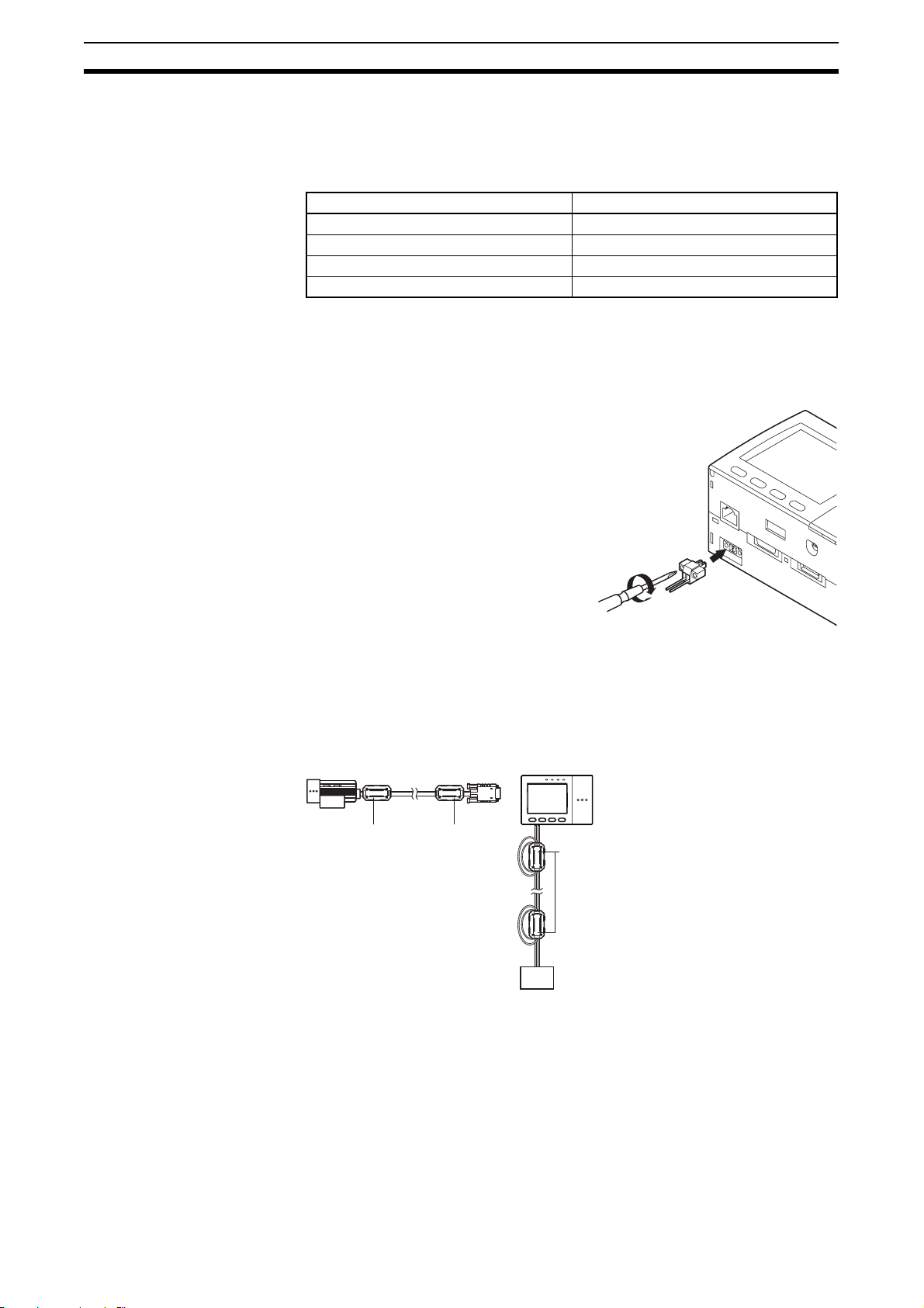
1. Loosen the two screws on the top of
the Power connector (male) using a
flat-blade screwdriver.
2. Insert the DC power terminal (wire)
into the Power connector (male) and
tighten the two screws on the top of
the Power connector to fasten the
power terminal with the screwdriver.
Tightening torque: 0.22 to 0.25 Nm.
3. Plug the Power connector (male) into
the Controller’s Power connector (female).
4. Tighten the two screws on the left and right of the Power connector (male)
with the screwdriver to fasten it. Tightening torque: 0.22 to 0.25 Nm.
+
-
24 VDC
1-2-2 Attaching Ferrite Cores
Attach ferrite cores (supplied) to both ends of the camera's cable and the
Controller's power cable, respectively.
Ferrite coreFerrite core
Ferrite core
When attaching ferrite cores to the
Controller's power cable, pass the
cable once through each ferrite core.
-
+
DC power
supply
6
1-2 Connecting the Devices Preparation
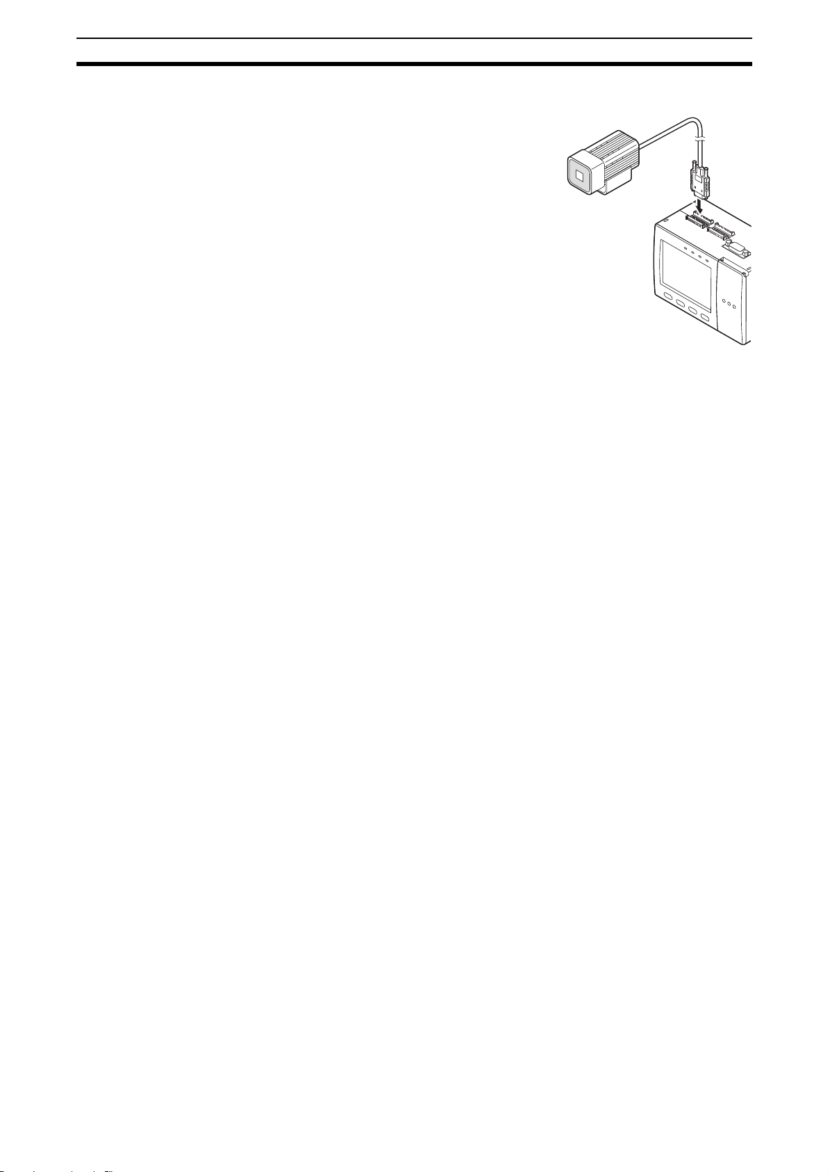
1-2-3 Connecting the Camera to the Controller
1. Insert the camera’s connector into the
Controller’s Camera connector.
2. Tighten the two fastening screws of the
Controller’s Camera connector.
Tightening torque: 0.15 Nm.
Important Do not touch the terminals inside the connector.
Important Fasten the connector while making sure that it is not subjected to vibration or
shock.
Important Do not mount the Controller in such a way that a load is steadily applied on
the connector, for example, with tension applied to the cables.
Disconnection procedure
Loosen the fastening screws (two locations) to unlock the camera’s cable, and
then pull the camera’s cable connector straight out.
Important Be sure to hold the connector of the camera to disconnect it. Failure to do so
may damage the camera’s cable.
Important Do not touch the terminals inside the connector.
7
1-3 Installing the Controller Preparation
1-3 Installing the Controller
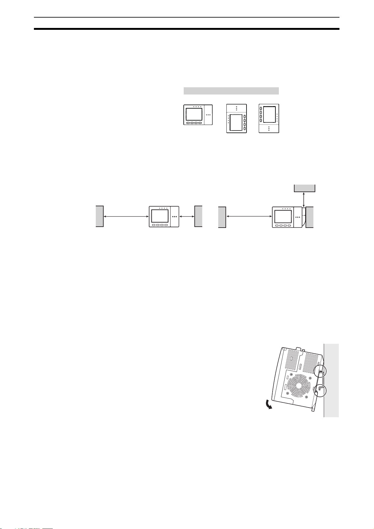
1-3-1 Installation Precautions
To improve heat radiation, install the Controller only in the orientation show
below.
Upward
Right
Important Install the Controller so that the distance between the Controller and other
devices is at least the dimensions shown in the figure below to improve the
ventilation.
When installing Controller only:
When installing the Controller With the Exhaust Unit
attached:
Wrong Wrong
Min. 15 mm
Min.
50 mm
Important Keep the ambient temperature less than 50 °C. If the ambient temperature is
higher than 50 °C, install a fan forced cooling system or an air conditioner to
keep the temperature lower than 50 °C.
Important Avoid mounting on a panel, in which high-voltage emitting devices are
installed to prevent ZFX-C operation from being affected by noise.
Important Allow at least 10 m between the Controller and power lines to keep noise at a
low level in the operating environment.
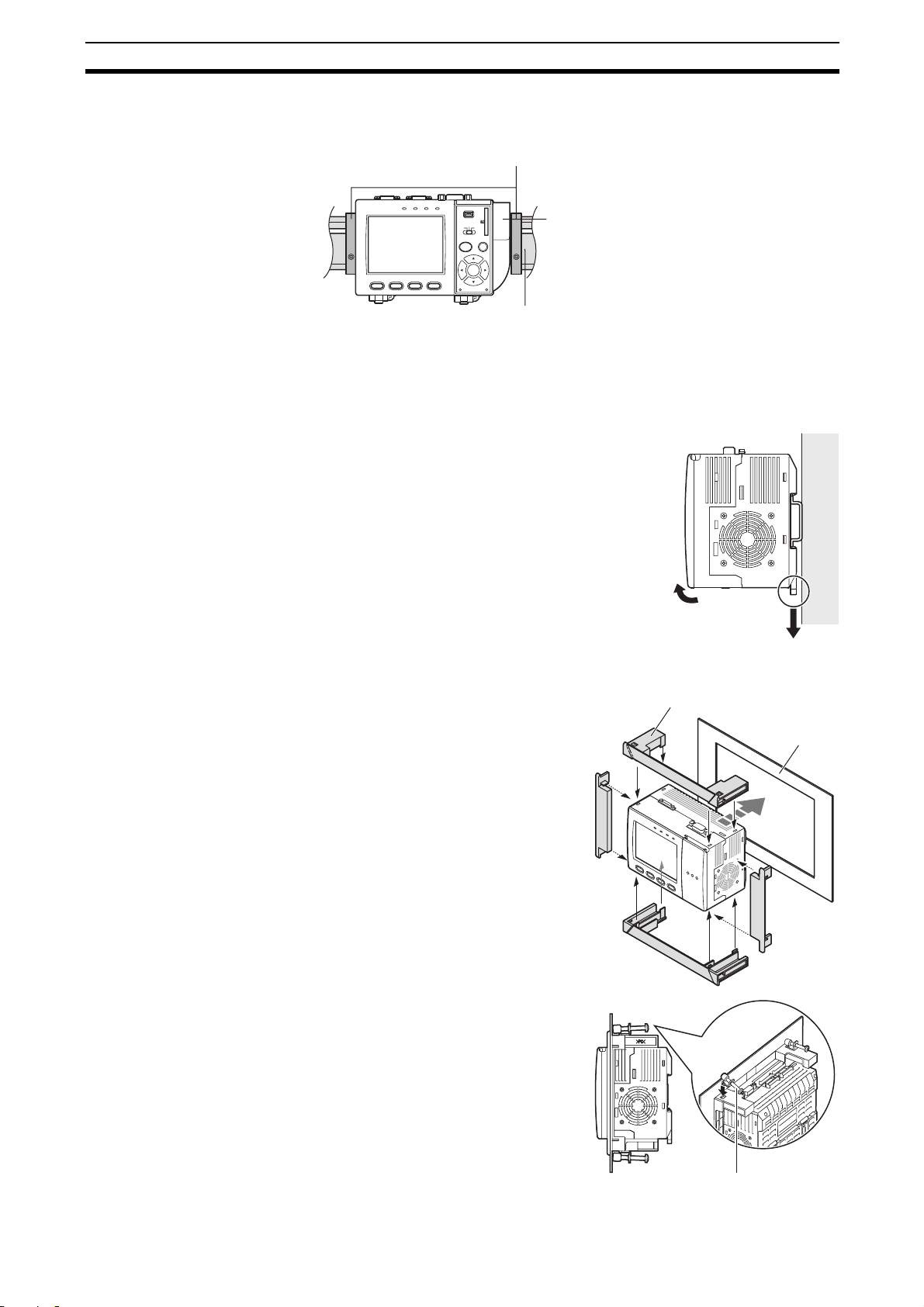
1-3-2 Installing on the DIN Track
1. Hook the Controller’s upper hook onto the
DIN track.
2. Push the Controller down onto the DIN track
until its lower hook is snapped into place.
Min.
15 mm
Min.
50 mm
1
2
Important Attach the End Plate (sold separately) to both sides of the Controller on the
DIN track.
8
1-3 Installing the Controller Preparation
Important Attach the Exhaust Unit (supplied) to the Controller when installing other
devices adjacently on the same DIN track as the Controller.
End Plate (sold separately)
PFP-M
Removing procedure
1. Pull the Controller’s lower hook downwards.
2. Lift up the Controller from its bottom to re-
OMRON
OUTPUT
RUN
ZFX-C10
1234
USB
ENABLE
ERROR
DIN track (sold separately)
SD
CARD
ADJ
MENU RUN
AUTO ESC
SET
PULL OPEN
PFP-100N (1 m)
PFP-50N (0.5 m)
PFP-100N2 (1 m)
move it from the DIN track.
Exhaust Unit
1
2
1-3-3 Mounting on the Panel
1. Install the long Panel Mount
Adapters on the four holes on the
Controller.
2. Install the short Panel Mount
Adapters on the two holes on the
long Panel Mount Adapter.
3. Install the Controller with Mount
Adapters attached onto the panel
from the front.
4. Hook the hooks of the mounting
bracket onto the two holes (two
each at top and bottom) of the
longer Mount Adapters and tighten the screws.
Tightening torque: 1.2 N•m.
5. Make sure that the Controller is
firmly fixed on the panel.
Panel mount adapters
Panel
1
3
2
2
1
4
Mounting bracket
9
1-4 Installing the Intelligent Cameras Preparation
0
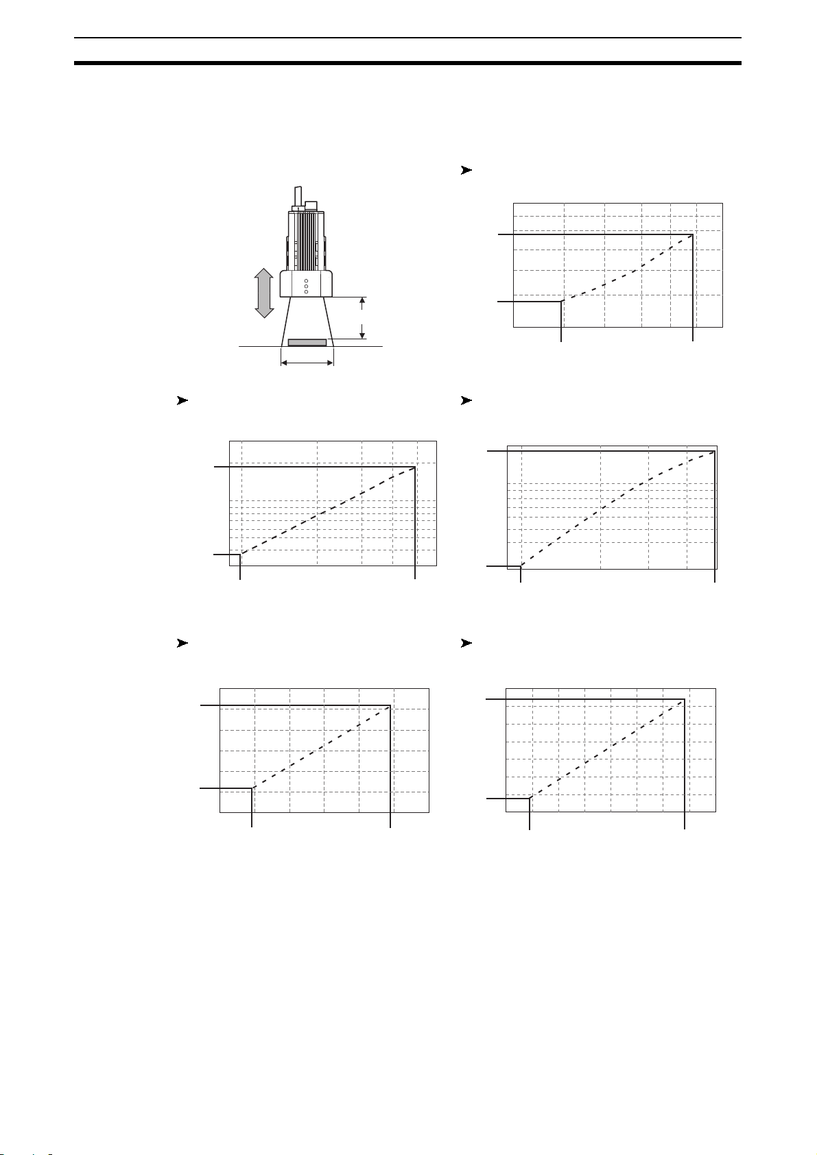
1-4 Installing the Intelligent Cameras
1-4-1 Optical chart
ZFX-SC10/SR10
Setting distance L (mm)
60
50
49
Setting distance (L)
Detection range (H)
ZFX-SR50 ZFX-SC50/SC50W
Setting distance L (mm)
300
194
100
38
30
9
9.8 49
Detection range H (mm)
ZFX-SC90/SC90W ZFX-SC150/SC150W
Setting distance L (mm)
160
142
6
34
0
Setting distance L (mm)
190
187
100
31
30
9.8
Setting distance L (mm)
240
227
4.9
Detection range H (mm)
Detection range H (mm)
104
8.9
49
10
67
115
180
100
89
12080
Detection range H (mm)
100
40
49
70
Detection range H (mm)
10040
89
Note • The lens has a fixed focal point. The actual detection range and focal point
vary from lens to lens, so adjust the distance to the measurement target
after replacing the lens or camera.
• The camera mounting distance listed in the following tables is an approximate value. Mount the Camera so that the distance to the measurement
target can be adjusted easily.
• If the object size and detection range are incompatible, use a combination
of a camera (without lighting), standard CCTV lens and light source.
160
148
1-4 Installing the Intelligent Cameras Preparation
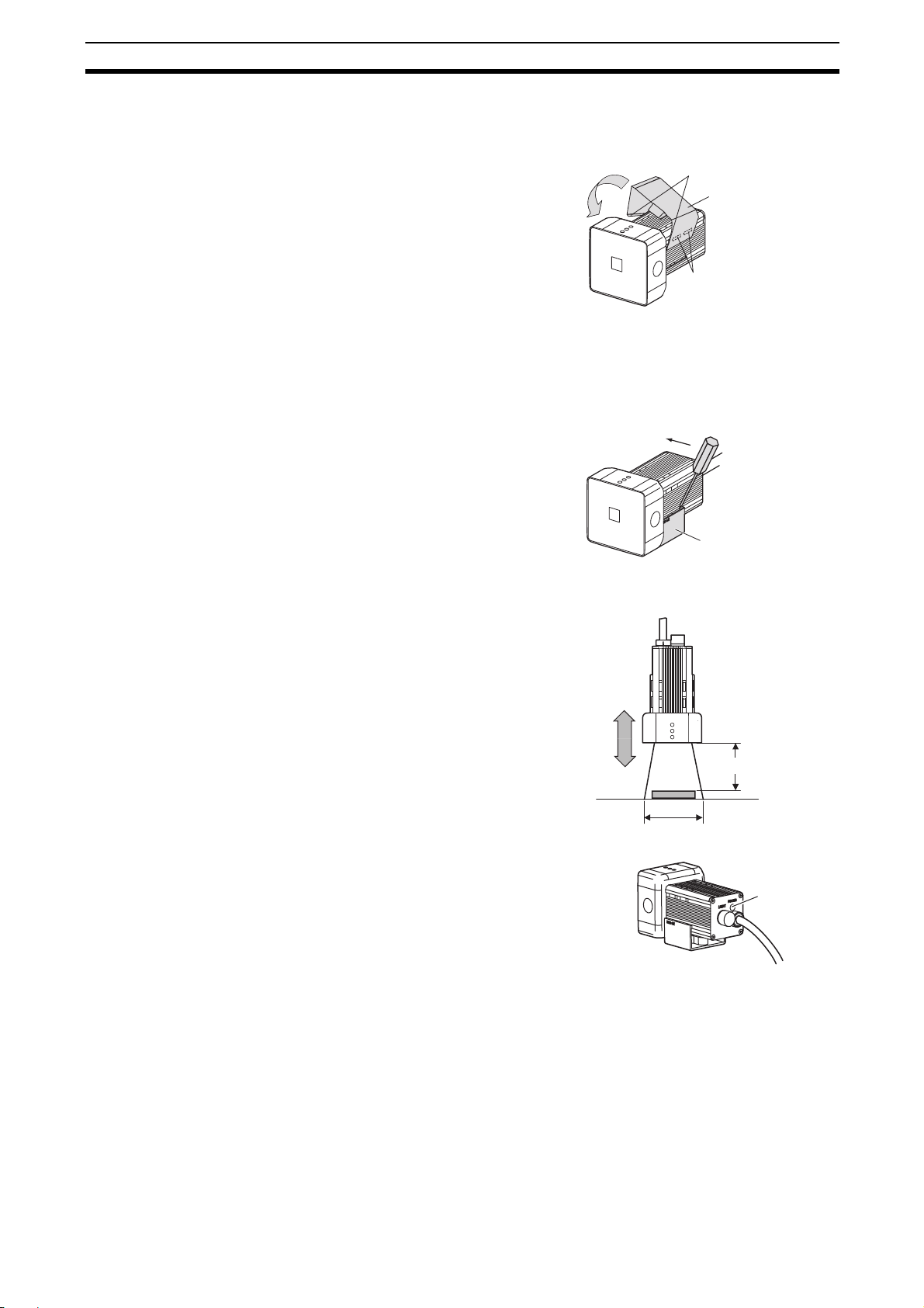
1-4-2 Installing the mounting fixture
The mounting fixture can be installed on all of the four mounting surfaces.
1. Align the two hooks on one side of
the mounting fixture with the two
grooves on the camera body.
2. Push the other hook down until it
is snapped into place.
Make sure that the mounting fixture is firmly fixed on the camera.
3. Fasten the mounting fixture at the
mounting location with screws.
Tightening torque
M4: 1.2 Nm
1/4”-20 UNC: 2.6 Nm
Removal procedure
1. Insert a screwdriver into the gap
(one of the two gaps) between the
mounting fixture and the camera
case, and remove the mounting
fixture.
Hooks
Mounting
fixture
Grooves on camera
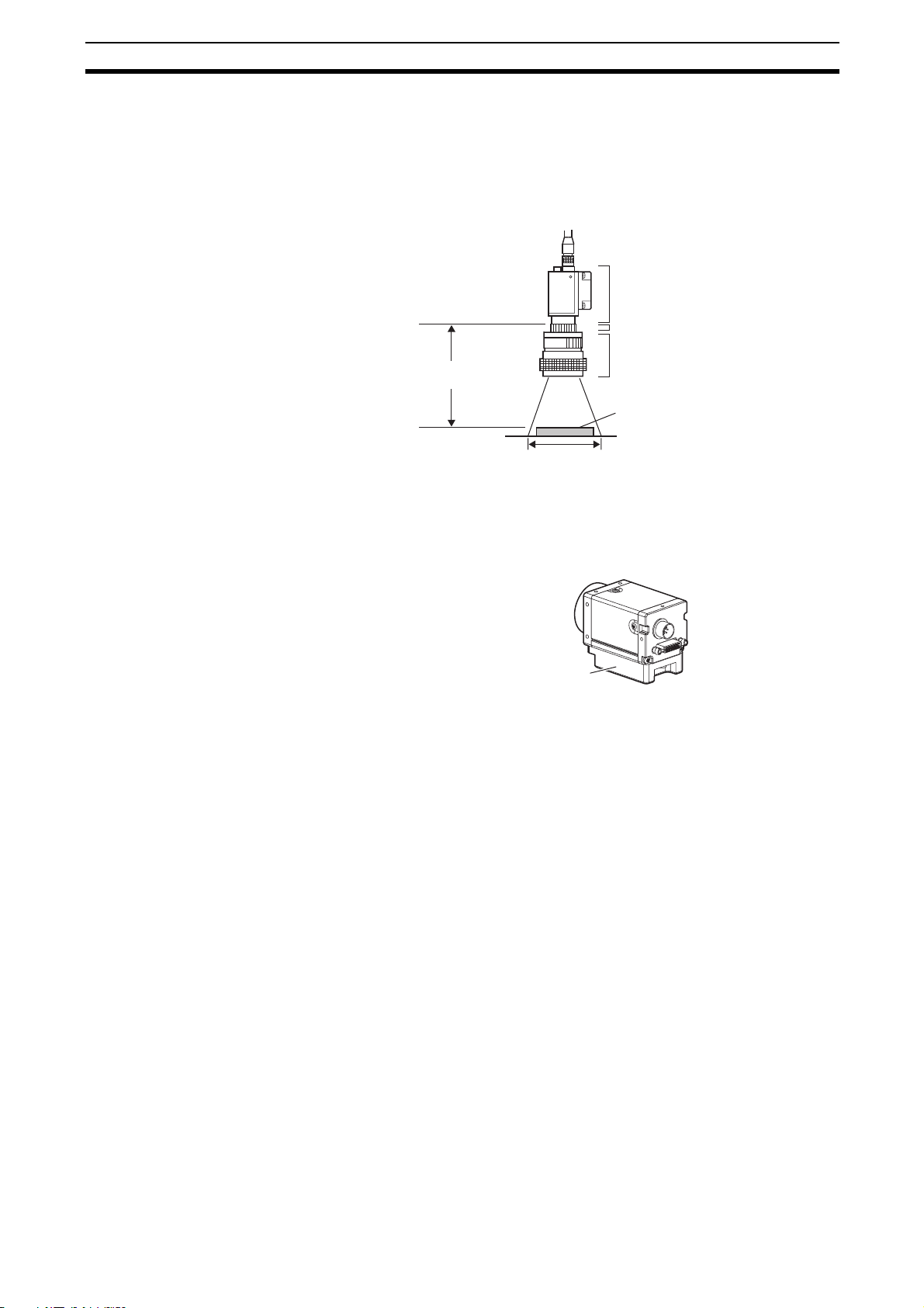
1-4-3 Adjusting the camera focus
1. Adjust the distance between the
camera and the measurement target and fasten the camera.
Refer to the optical chart and set
the camera in a position so that
the area to be checked is within
the detection area (LCD monitor).
“Optical chart” p. 10.
2. Turn the focus adjustment control
to the left and right to adjust the
focus.
Mounting fixture
Setting distance (L)
Detection range (H)
Focus
adjustment
control
Note First turn the focus adjustment control slightly to the left and right, to make
sure that the Focus adjustment control is not at the upper or lower limit positions. Do not exert unnecessary force to turn the control at the upper or lower
limit positions as this might damage the control.
(For ZFX-SC90_/SC150_, the control stops turning at the nearest position. It
turns free at the farthest position.)
11
1-5 Installing the C-mount Cameras Preparation
1-5 Installing the C-mount Cameras
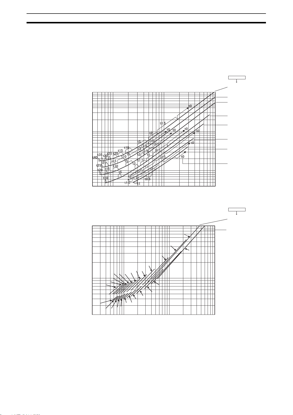
1-5-1 Optical chart
The values in the following chart are approximations, and the Camera must be
adjusted after it is mounted.
Lens model
3Z4S-LE
ML-5018
10000
ML-3519
ML-2514
ML-1614
Camera distance A(mm)Camera distance A(mm)
1000
10000
1000
100
40
4 10 100 1000
Detection range(mm)
t0
t2
t5
t10
t20
t15
t25
t35
t40
t30
t45
t50
t60
t10
t50
200
2 10 100 1000
t45
t40
t35
t30
t25
t20
t15
t2
t5
t0
Detection range(mm)
ML-1214
ML-0813
ML-0614
t: Extension tube
Example
t0: Extension tube
is not required.
t5: 5-mm extension
tube is required.
Lens model
3Z4S-LE
ML-10035
ML-7527
12
The X axis of the optical chart shows detection range L (mm), and the Y axis
shows the camera distance A (mm). The curves on the optical chart show the
relationship between the detection range and camera distance for each CCTV
lens. The values are significantly different for each lens, so double-check the
model of the lens before using the graph. The “t” values indicate the lengths of
the Extension Tubes. The value “t0” shows the case where an Extension Tube
1-5 Installing the C-mount Cameras Preparation
is not required and the value “t5.0” shows the case where a 5-mm Extension
Tube is used.
Example
When a 3Z4S-LE ML-5018 CCTV Lens is being used and a detection range of
40 mm is required at the measurement target, a camera distance of 500 mm
and 5-mm Extension Tube are required.
Camera
Extension Tube t_ (mm)
Lens
Camera distance A (mm)
Measurement object
Detection range L (mm)
1-5-2 Installing the Camera Mounting Base
The camera mounting base mounted on the bottom of the camera can be
installed on all of the four mounting surfaces. To change the mounting surface,
remove the three mounting screws (M2 x 6) from the camera.
Camera Mounting Base
• Tightening torque when fastening the camera mounting base at the
mounting location
M4: 1.2 Nm
1/4”-20 UNC: 2.6 Nm
13
1-6 Installing the External Lightings (Only For ZFX-SC50/SC90) Preparation
1-6 Installing the External Lightings (Only For ZFX-SC50/SC90)
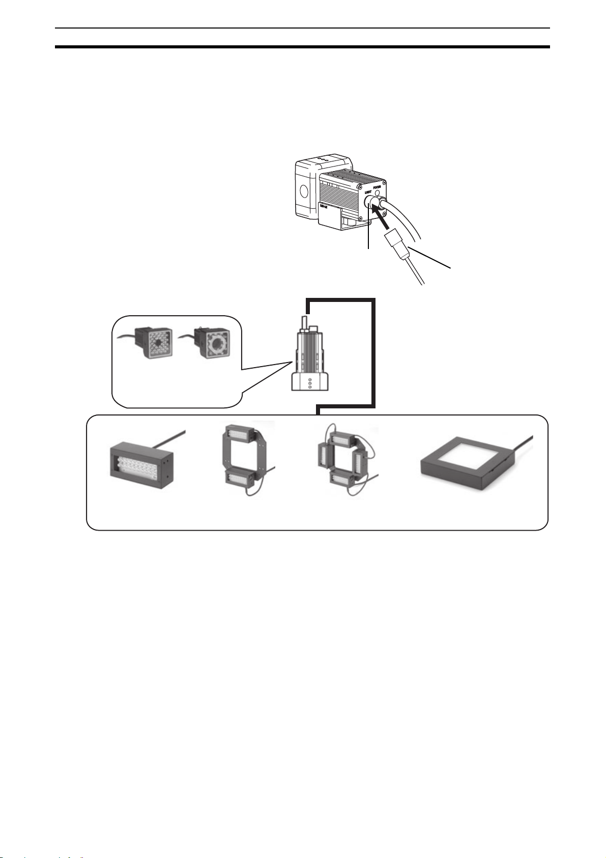
1-6-1 Connecting the Optional Lighting to the Camera
The optional lighting can be mounted to the rear connector of the camera
(ZFX-SC50_/SC90_) with a single motion. Since the power is supplied from
the camera side, no power supply is required for the optional lighting.
ZFX-SC50 ZFX-SC90
Optional lighting can be used
with these two Cameras.
Bar Lighting
Double Bar Lighting
ZFV-LTL01
Remove the cap from the optional lighting connector on the rear of the camera.
ZFV-LTL02
Low-angle Bar Lighting
ZFV-LTL04
Connector of the
optional lighting
Through-beam Lighting
ZFV-LTF01
14
1-7 Installing the External Lightings (Only For C-mount Camera (ZFX-S/SC)) Preparation
1-7 Installing the External Lightings (Only For C-mount Camera (ZFX-S/SC))
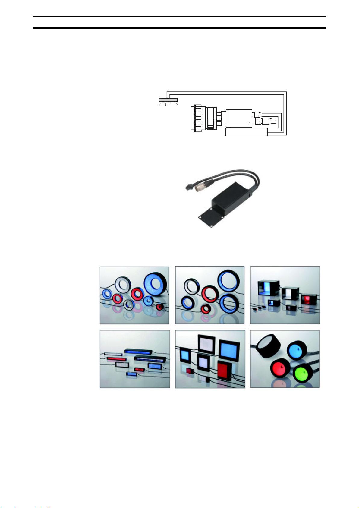
1-7-1 Connecting the Optional Lighting to the camera
The optional lighting can be connected to the Strobe Controller. And the
Strobe Controller can be connected to the camera (ZFX-S/SC). No power
supply is required for the optional lighting.
Strobe Controller
Strobe Controller
3Z4S-LT MLEK-C100E1TSX
External Lighting
3Z4S-LT Series
The lighting that current consumption is 1.0A or less can be connected
15

1-7 Installing the External Lightings (Only For C-mount Camera (ZFX-S/SC)) Preparation
16
2-1 Operation Mode
ADJ
MENU
RUN
MENU mode This mode is for setting the
Main Operation
The ZFX-C has the following three
ADJ
MENU
RUN
Mode switch
Mode Description
measurement conditions.
The easy-to-follow iconbased display allows operations to be performed intuitively.
modes. Switch to the desired mode
before you start operation. To switch
the operation mode, use the mode
switch.
SECTION 2
Top Screen
Top menu
LIVE
TEA
ADJ mode This mode is for checking
the measurement status and
adjusting conditions. Measurement results are only
displayed on the monitor and
are not output.
Important
Trigger input isn’t acceptable
RUN mode This mode is used for per-
forming actual measurement. Measurement results
are displayed on the monitor and output.
Important
Measurement trigger by
menu operation is to push
[SET]-key & [UP]-key
Bank
Tool
Top Screen
353ms
OK
Camera 0
0.Bank00
0.Pattern Search
Judge OK
Correlation 92
Position X 462
Position Y 352
Angle 15
Previous Next
Top Screen
353ms
OK
Camera 0
0.Bank00
0.Pattern Search
Judge OK
Correlation 92
Position X 462
Position Y 352
Angle 15
Previous Next
System
Setup
Individual result
TEA
Dsplay SW
Individual result
TEA
Dsplay SW
Save
Adjust
Capture
17
2-2 Adjusting the brightness of image Main Operation
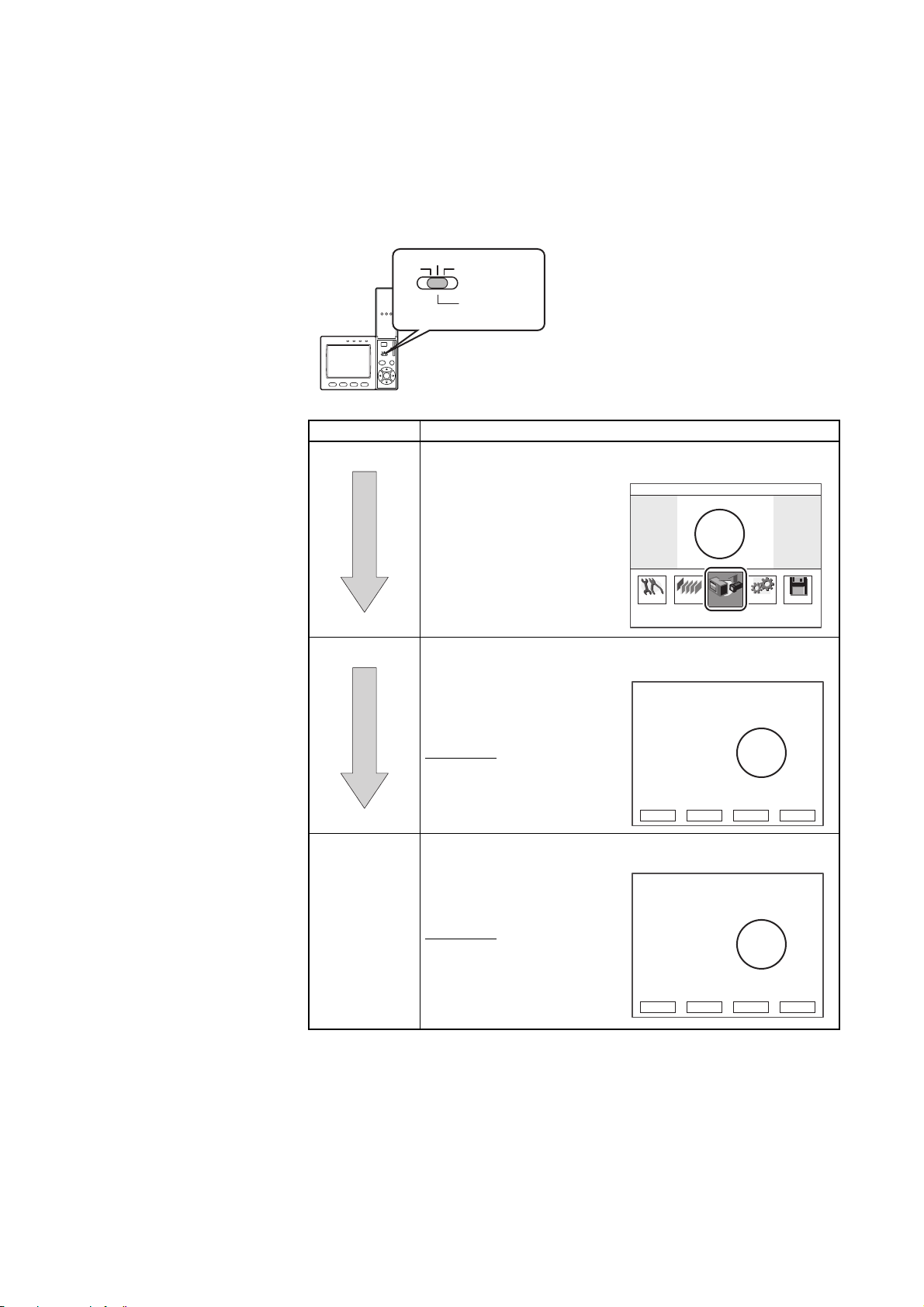
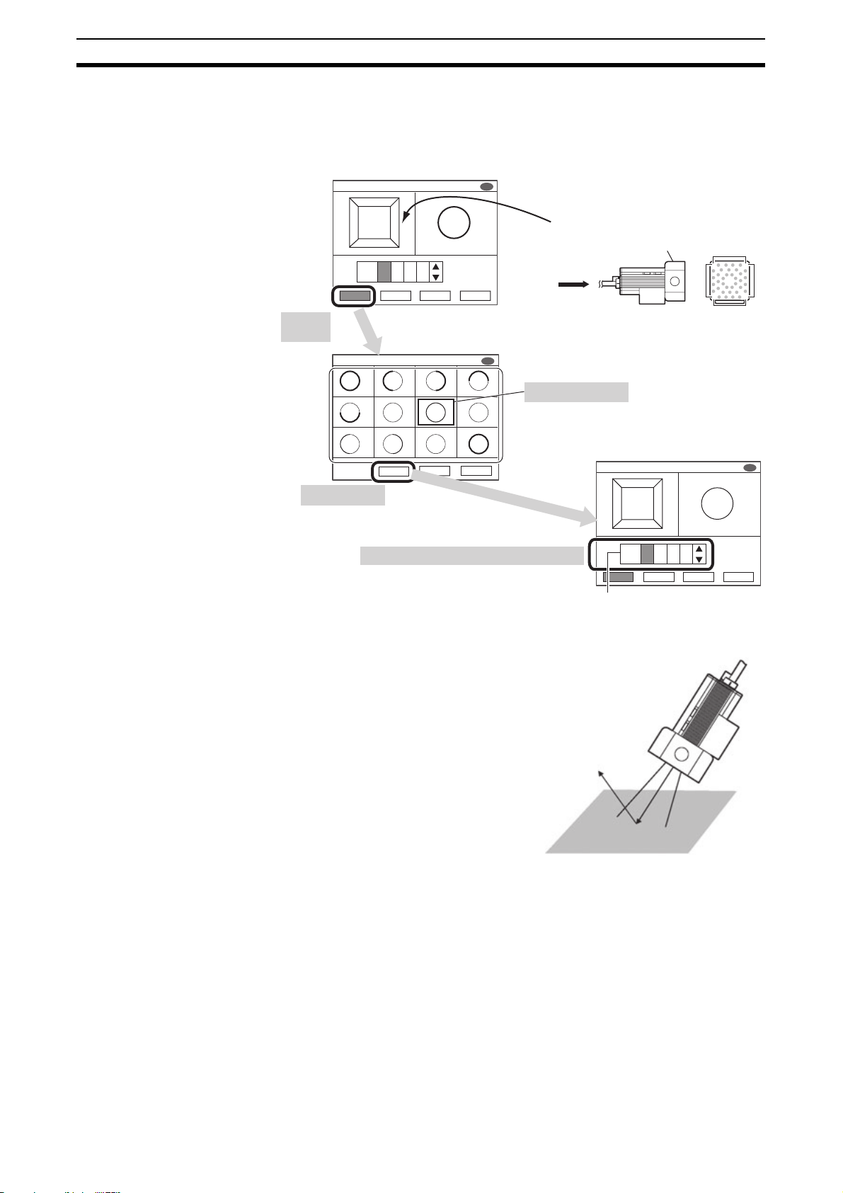
2-2 Adjusting the brightness of image
2-2-1 Lighting Intensity (Only the intelligent Cameras)
MENU mode - [Setup] - [Cameras] - [Light Control]
1. Push
"Auto"
Light Control
A
DB
C
5
5
5B5
A
D
ALL
Auto
C
CancelApply Capture
The thumbnails of images automatically captured
under differen illumination patterns are displayed
TEA
SD
How blocks are displayed
Top surface (surface printed with model No.)
View from
this side
A
D
C
B
Light Control
TEA TEA TEA TEA
TEA TEA TEA TEA
TEA TEA TEA
Apply
Cancel
SD
Capture
3. Push "Apply"
The lighting condition of the
selected image is displayed
4. Fine-adjust these conditions as required.
Important If the workpiece is glossy, install the
camera at an angle to prevent mirror
reflection light from being picked up by
the camera.
2. Select the image
A
D
C
ALL
Auto
Auto
Amount of emitted light
Mirror reflection light
Light Control
B
2A3B2C3
Apply Cancel Capture
TEA
D
SD
18
 Loading...