

Omron ZEN-20C1AR-A-V2, ZEN-10C1AR-A-V2, ZEN-10C1DR-D-V2, ZEN-10C1DT-D-V2, ZEN-20C1DR-D-V2 Datasheet
...
Programmable Relay ZEN V2 Units 1
Programmable Relay
ZEN V2 Units
Please read and understand this catalog before purchasing the
products. Please consult your OMRON representative if you have any
questions or comments. Refer to “Warranty and Application
Considerations” on page 36, and “Precautions for Safe Use” on page 34.
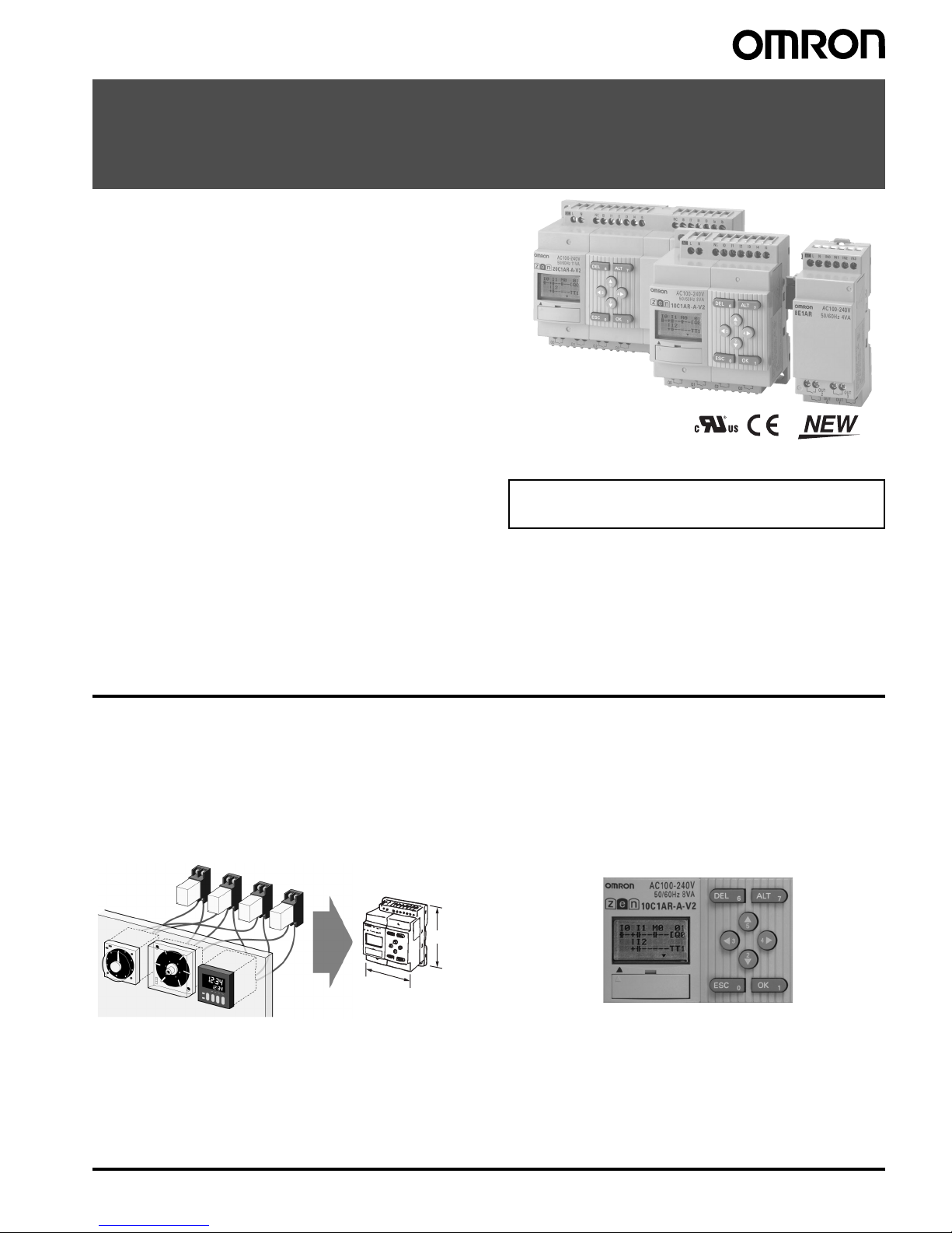
Even Broader Applications with Increased
Functionality and Higher Precision
• Increased functionality in a compact body (70 mm wide × 90 mm
high).
• Easy programming is available using the LCD and operation
buttons. (See note 1.)
• This single Unit easily provides relay, timer, counter, and time
switch functions.
• Expansion is easy with Expansion I/O Units, allowing up to 44
I/O points. (See note 2.)
• Economy-type and Communications-type CPU Units have been
added to series.
• Improved Weekly Timers (See note 1.)
Increased timing accuracy with a monthly deviation of ±15 s
max. Multiple-day operation and pulse output operation have
been added.
• Select from two power supply options:
100 to 240 VAC or 12 to 24 VDC.
Note: 1. Not supported for ZEN-@C2@@-@-V2 models.
2. When using CPU Units with 20 I/O points.
The information in this document applies to V2 Units.
Refer to page 28 for details on differences with previous
products.
Features
■ Easy and Simple Programming for Automatic Small-scale Control
Saves Space, Wiring, and Installation Steps
• Versatile functionality in a compact body (70 mm wide × 90 mm
high).
• This single Unit easily provides relay, timer, counter, and time
switch functions. Wiring work is greatly reduced because separate
wiring is not required for devices such as timers and counters.
Easy Programming
The LCD screen comes with 8 operation buttons on the front panel to
enable programming in ladder view format. The LCD screen also has
a backlight, making it easier to see when the ZEN is used in dark
locations.
Note: Not supported for ZEN-@C2@@-@-V2 models.
90 mm
70 mm
2 Programmable Relay ZEN V2 Units
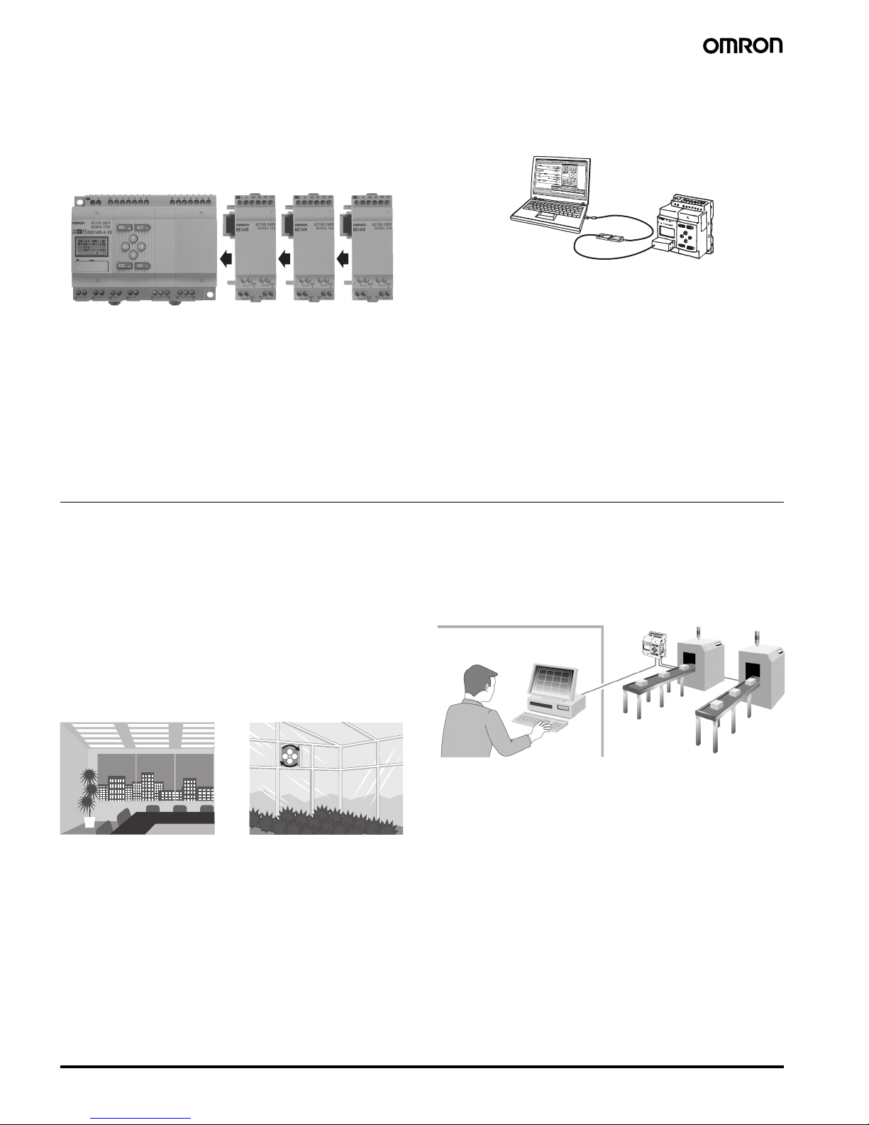
Flexible Expansion Enables Up to 44 I/O
Points
Up to three Expansion I/O Units can be connected if there are not
enough I/O points. Expansion I/O Units are only 35 mm wide.
Note: CPU Units with 10 I/O points can be expanded to 34 I/O points.
Expansion I/O Units cannot be connected to Economy-type
CPU Units.
Support Software with Simulation Function
• Programs can be easily written, saved, and monitored by personal
computer.
• Programs can be simulated on the personal computer without
connecting to the ZEN.
Note: For notebook computers that do not have an RS-232C serial
port, connect the computer to the ZEN by connecting an
OMRON CS1W-CIF31 USB-Serial Conversion Cable to the
ZEN-CIF01 Connecting Cable.
Other Versatile Functions
• Use of a Memory Cassette makes it easy to copy and save
programs.
• Equipped with two analog input channels (CPU Units with DC
power supply only).
• Password function ensures security. (See note.)
• Multi-language display in six languages (English, Japanese,
German, French, Spanish, Italian). (See note.)
• Display user-set messages or analog-converted values. (See note.)
Note: Not supported for ZEN-@C2@@-@-V2 models.
■ Enhanced Features of V2 CPU Units
Improved Weekly Timer and Calendar Timer
Functions
Note: Not supported for ZEN-@C2@@-@-V2 models.
• The time precision has been increased.
Conventional model: 2-min difference/month
↓
-V2 models: ±15-s difference/month (at 25°C)
• Multiple-day operation and pulse-output operation are now
possible.
• These improved functions are convenient for time-controlled
applications such as lighting and air conditioning control.
Economy-type Added to the Series
• Economy-type CPU Units with a more affordable price have been
added to the series, although Expansion I/O Units cannot be
added.
12 to 24 VDC Line Voltage Operation
Operation is now possible with 12 VDC.
Expansion I/O Units have been reduced to
half-size (35 mm wide).
RS-485 Communications Model Added to
Series
Production line conditions can be remotely monitored by monitoring
the ZEN control status.
More Precise Analog Input
Conventional model: ± 10% FS → -V2 models: ± 1.5% FS
DC power supply models are equipped with two analog inputs (0 to
10 V). There are four analog comparators. The increased precision
makes it even easier to use the Unit in simple control applications
with voltage, current, temperature, and other analog values.
8-digit Counter, 150-Hz Counter
• An 8-digit counter and 8-digit comparator have been added.
• The maximum count for DC power supply models is 150 Hz.
Twin-timer Operation Added
Twin-timer operation allows you to set ON and OFF times separately,
greatly simplifying intermittent operation.
Lighting control Air conditioning control
Office
Production line
Programmable Relay ZEN V2 Units 3
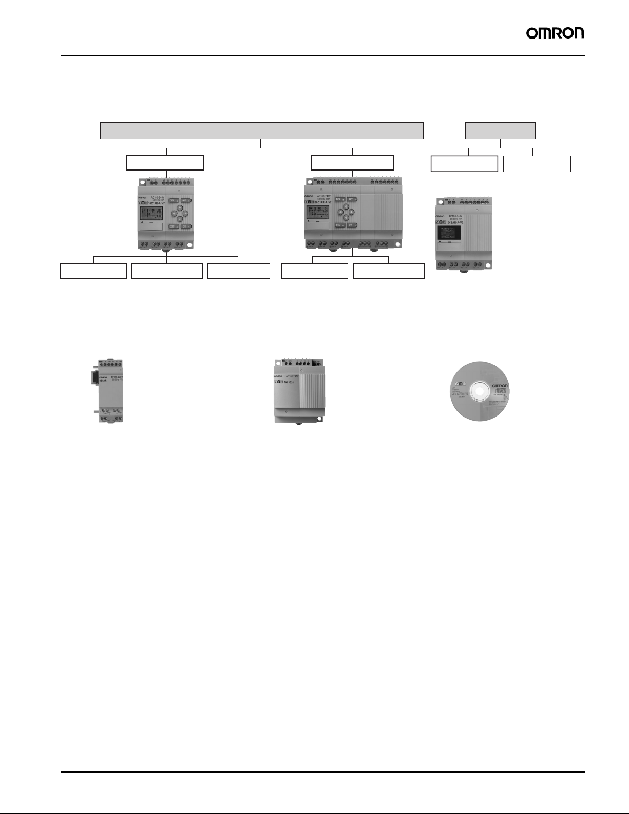
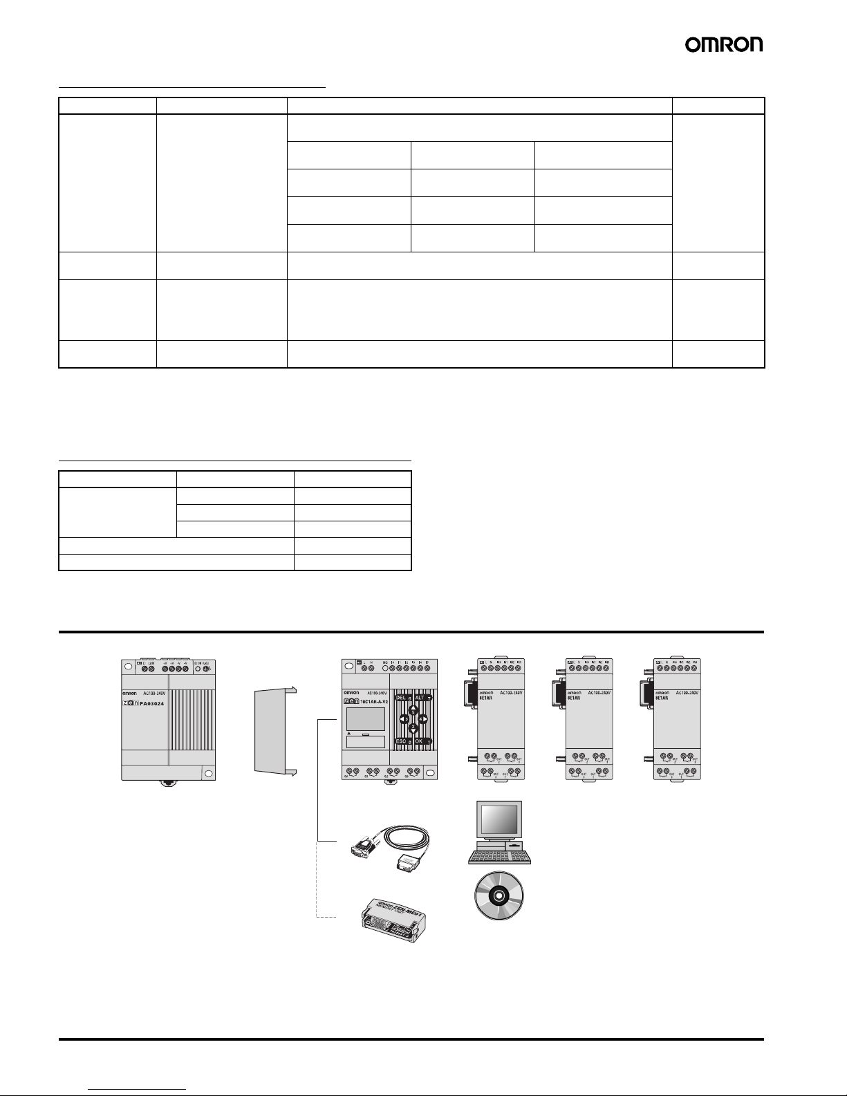
■ Series Configuration
CPU Units
Power supply voltage: 100 to 240 VAC, 12 to 24 VDC, Output: Relay, transistor output
With LCD display, operation buttons, and calendar/clock function LED type
10 I/O points
Standard LCD type Economy type Standard LCD type Economy type
Communications type
20 I/O points
10 I/O points 20 I/O points
ZEN-10C1@ ZEN-10C3@ ZEN-10C4@ ZEN-20C1@ ZEN-20C3@
ZEN-10C2@
(10 I/O points)
ZEN-20C2@
This CPU Unit has no LCD,
operation buttons, or
calendar/clock function.
Expansion I/O Units
cannot be connected.
Expansion I/O Units
cannot be connected.
RS-485 communications
type.
E
xpansion
I/O Uni
ts
Only 35-mm wide.
4 input, 4 output points
P
ower Supply Unit
Same shape and design as ZEN.
24 VDC, 30 W
S
upport Software
Allows easy programming and
operation simulation.

4 Programmable Relay ZEN V2 Units
Model Number Structure
■ Model Number Legend
Note: This model number legend includes combinations that are not available.
Please check “List of Models” for availability.
CPU Units
1. Number of I/O points
10: 6 inputs and 4 outputs (See note.)
20: 12 inputs and 8 outputs
2. Type classifier
1: Standard LCD type with display
2: LED type without display
3: Economy type with display
(Expansion I/O Units cannot be connected.)
4: Communications type with display
3. Input type
A: AC input
D: DC input
4. Output type
R: Relay
T: Transistor
5. Supply voltage
A: AC power supply
D: DC power supply
Note: The Communications-type CPU Unit has 6 inputs and 3 outputs.
Expansion I/O Units
1. Number of I/O points
8: 4 inputs and 4 outputs
2. Unit version classifier
E1: Can connect to V2 CPU Units (See note.)
3. Input type
A: AC input
D: DC input
4. Output type
R: Relay
T: Transistor
Note: Use a ZEN-8E@@/-4E@ to connect to pre-V1 and V1 CPU Units.
ZEN-@C@@@-@-V2
1
234 5
ZEN-8E1@@
1
234
This data sheet is provided as a guideline for selecting products. Be sure to refer to the following user manuals for application precautions
and other information required for operation before attempting to use the product.
ZEN Operation Manual (Cat. No. Z211)
ZEN Communications Manual (Cat. No. Z212)
ZEN Support Software Operation Manual (Cat. No. Z184-E1-03)
The PDF versions of these manuals can be downloaded from the following website.
ZEN Website http://www.zen.omron.co.jp/eng/index.html
Programmable Relay ZEN V2 Units 5
Ordering Information
■ List of Models
CPU Units and Expansion I/O Units
Note: 1. Programming is not possible using only the CPU in the LED-type CPU Unit. ZEN Support Software or a Memory Cassette is required.
2. Cannot be connected to pre-V1 and V1 CPU Units.
3. The ZEN-8E1AR cannot be connected to a CPU Unit with DC power supply.
Power Supply Unit
Note: Refer to the ZEN-PA03024 Datasheet (Cat. No. L103) for detailed specifications.
Unit Name No. of
I/O
points
LCD
display
Powe r supp ly
voltage
Inputs Outputs Buttons,
calendar,
and clock
Analog
input
Model
CPU
Units
Standard
LCD type
10 Yes 100 to 240 VAC 6 100 to 240 VAC 4 Relays Yes No ZEN-10C1AR-A-V2
12 to 24 VDC 12 to 24 VDC Yes ZEN-10C1DR-D-V2
Transistors ZEN-10C1DT-D-V2
20 100 to 240 VAC 12 100 to 240 VAC 8 Relays No ZEN-20C1AR-A-V2
12 to 24 VDC 12 to 24 VDC Yes ZEN-20C1DR-D-V2
Transistors ZEN-20C1DT-D-V2
LED type
without
display
(See note 1.)
10 No 100 to 240 VAC 6 100 to 240 VAC 4 Relays No No ZEN-10C2AR-A-V2
12 to 24 VDC 12 to 24 VDC Yes ZEN-10C2DR-D-V2
Transistors ZEN-10C2DT-D-V2
20 100 to 240 VAC 12 100 to 240V AC 8 Relays No ZEN-20C2AR-A-V2
12 to 24 VDC 12 to 24 VDC Yes ZEN-20C2DR-D-V2
Transistors ZEN-20C2DT-D-V2
Economy
type
(Expansion
I/O Units
cannot be
connected)
10 Yes 100 to 240 VAC 6 100 to 240 VAC 4 Relays Yes No ZEN-10C3AR-A-V2
12 to 24 VDC 12 to 24 VDC Yes ZEN-10C3DR-D-V2
20 100 to 240 VAC 12 100 to 240 VAC 8 Relays No ZEN-20C3AR-A-V2
12 to 24 VDC 12 to 24 VDC Yes ZEN-20C3DR-D-V2
Communications type
10 100 to 240 VAC 6 100 to 240 VAC 3 Relays No ZEN-10C4AR-A-V2
12 to 24 VDC 12 to 24 VDC Yes ZEN-10C4DR-D-V2
ZEN Kit Set containing CPU Unit (ZEN-10C1AR-A-V2), Connecting Cable, ZEN Support Software, and manual. ZEN-KIT01-EV4
Set containing CPU Unit (ZEN-10C1DR-D-V2), Connecting Cable, ZEN Support Software, and manual. ZEN-KIT02-EV4
Expansion I/O Units 8 --- 100 to 240 VAC 4 100 to 240 VAC 4 Relays --- ZEN-8E1AR
(See notes 2, 3.)
12 to 24 VDC 12 to 24 VDC ZEN-8E1DR
(See note 2.)
---
Transistors ZEN-8E1DT
(See note 2.)
Power ratings Input voltage Output voltage Output current Model
30 W 100 to 240 VAC 24 VDC 1.3 A ZEN-PA03024
6 Programmable Relay ZEN V2 Units
Accessories (Order Separately)
Note: 1. Memory Cassettes created using a CPU Unit can be read to other CPU Units, regardless of which model is used. Restrictions, apply, however, to
the functions that can be used, depending on the CPU Unit version combination. For details, refer to “Memory Cassette and CPU Unit
Combinations” on page 33.
2. Standard LCD-type, Economy-type, and Communications-type CPU Units (i.e., excluding ZEN-@C2@@-@-V2 models).
3. LED-type CPU Unit without display (i.e., ZEN-@C2@@-@-V2 models).
Mounting Accessories (Order Separately)
System Configuration
Note: 1. Up to 3 Expansion I/O Units can be connected to any type of CPU Unit except for Economy-type CPU Units. Expansion I/O Units with AC Inputs,
however, cannot be connected to CPU Units with DC Power Supplies.
2. The Connecting Cable and Memory Cassette cannot be connected to the ZEN at the same time.
3. Programs cannot be written to LED-type CPU Units (i.e., ZEN-@C2@@-@-V2 models) without the ZEN Support Software or a Memory Cassette.
Name Specifications Remarks Model
Memory Cassette EEPROM (for data
security and copying)
Enables programs and parameter settings to be saved or copied to another
ZEN. (See note 1.)
ZEN-ME01
LCD-type CPU Unit with
display (See note 2.)
LED-type CPU Unit without
display (See note 3.)
Transfer from ZEN to
Memory
Supported Not supported
Transfer from Memory
Cassette to ZEN
Supported Automatic transfer when
power turned ON
Memory Cassette
initialization
Supported Not supported
Connecting Cable 2 m RS-232C (9-pin D-
sub connector)
--- ZEN-CIF01
Battery Unit 10 years min. Battery life
(at 25
°C)
Ladder programs and parameter settings are saved to the CPU Unit EEP-ROM
but calendar, clock, and holding timer bits and holding timer/counter present
values are held by the capacitor. Therefore, if the power supply is interrupted
for 2 days or more (at 25°C), this data will be reset. Use a Battery Unit for
systems where the power supply may be interrupted for long periods.
ZEN-BAT01
ZEN Support
Software
Runs on Windows 95, 98,
2000, ME, XP, or NT 4.0.
Specifically designed for the ZEN (CD-ROM). ZEN-SOFT01-V4
Name Specifications Model
Mounting Track 50 cm (l)
× 7.3 mm (t) PFP-50N
1 m (l)
× 7.3 mm (t) PFP-100N
1 m (l)
× 16 mm (t) PFP-100N2
End Plate PFP-M
Spacer PFP-S
CPU UnitPower Supply Unit
Connecting Cable
Support Software
Memory Cassette
Battery Unit
Expansion I/O Units
Programmable Relay ZEN V2 Units 7
Specifications
■ Ratings
Note: 1. Can be mounted to 35-mm DIN Track.
2.
Item Specification
ZEN-@C@AR-A-V2/ZEN-8E1AR ZEN-@C@D@-D-V2/ZEN-8E1D@
Rated supply voltage 100 to 240 VAC, 50/60 Hz 12 to 24 VDC (DC ripple rate: 5% max.)
Operating voltage range 85 to 264 VAC 10.8 to 28.8 VDC
Power consumption CPU Units without Expansion I/O Units
• ZEN-10C1AR-A-V2/ZEN-10C2AR-A-V2/
ZEN-10C3AR-A-V2
100 V AC: 5 VA max.
240 V AC: 7 VA max.
• ZEN-10C4AR-A-V2
100 V AC: 6 VA max.
240 V AC: 8 VA max.
• ZEN-20C@AR-A-V2
100 V AC: 7 VA max.
240 V AC: 10 VA max.
CPU Units with three Expansion I/O Units
• ZEN-10C1AR-A-V2/ZEN-10C2AR-A-V2
100 V AC: 6 VA max.
240 V AC: 8 VA max.
• ZEN-10C4AR-A-V2
100 V AC: 7 VA max.
240 V AC: 9 VA max.
• ZEN-20C@AR-A-V2
100 V AC: 8 VA max.
240 V AC: 11 VA max.
Expansion I/O Units
• ZEN-8E1AR
100 V AC: 3 VA max.
240 V AC: 4 VA max.
CPU Units without Expansion I/O Units
• ZEN-10C@DR-D-V2
12/24 V DC: 3 W max.
(ZEN-10C3DR-D-V2: 2.8 W max.)
• ZEN-10C@DT-D-V2
12/24 V DC: 2 W max.
• ZEN-20C@DR-D-V2
12/24 V DC: 4 W max.
• ZEN-20C@DT-D-V2
12/24 V DC: 2 W max.
CPU Units with three Expansion I/O Units
• ZEN-10C@DR-D-V2
12/24 V DC: 4 W max.
• ZEN-10C@DT-D-V2
12/24 V DC: 3 W max.
• ZEN-20C@DR-D-V2
12/24 V DC: 5 W max.
• ZEN-20C@DT-D-V2
12/24 V DC: 3 W max.
Expansion I/O Units
• ZEN-8E1DR
12/24 V DC: 2 W max.
Inrush current ZEN-10C@AR-A-V2: 4.5 A max.
ZEN-20C@AR-A-V2: 4.5 A max.
ZEN-8E1AR: 4 A max.
ZEN-10C@D@-D-V2: 30 A max.
ZEN-20C@D@-D-V2: 30 A max.
ZEN-8E1DR: 15 A max.
Ambient temperature 0 to 55
°C (−25 to 55°C for ZEN-@C2@@-@-V2 models)
Ambient storage temperature
−20 to 75°C (−40 to 75°C for ZEN-@C2@@-@-V2 models)
Ambient humidity 10% to 90% (with no condensation)
Ambient conditions No corrosive gases
Mounting method Surface mounting, DIN track mounting (standard (vertical) installation and horizontal installation) (See notes 1
and 2.)
Ter m ina l bl ock Solid-line terminal block (use solid wire or fine-stranded wire)
Terminal screw tightening
torque
0.565 to 0.6 N·m (5 to 5.3 in-lb)
Degree of protection IP20 (Mounted inside a control panel)
Standard (Vertical) installation
Horizontal installation
8 Programmable Relay ZEN V2 Units
■ Characteristics
Note: 1. Up to 34 points for CPU Units with 10 I/O points. With Communications-type CPU Units, however, the CPU Unit has 6 inputs and 3 outputs, for a maximum
of 33 I/O points.
2. Not provided for LED-type CPU Unit without display (i.e., ZEN-@C2@@-@-V2 models).
■ Communications Specifications (Communications-type CPU Units)
Item Specification
Control method Stored program control
I/O control method Cyclic scan
Programming language Ladder diagram
Program capacity 96 lines (3 input conditions and 1 output per line)
Max. No. of control I/O points 44 points (See note 1.)
CPU Units with 20 I/O points: 12 inputs and 8 outputs
Expansion I/O Units: 4 inputs and 4 outputs each, up to 3 Units.
LCD display (See note 2.) 12 characters
× 4 lines, with backlight
Operation buttons (See note 2.) 8 (4 cursor buttons and 4 operation buttons)
User program backup Internal EEPROM, Memory Cassette (optional)
Power interruption hold Internal holding bit status, holding timer/counter present values, calendar and clock (year, month, day of month,
day of week, time)
• Super capacitor backup time: 2 days min. (25
°C)
• Life of optional battery: 10 years min. (25
°C)
Calendar and clock function
(See note 2.)
Accuracy:
±15 s/month (at 25°C)
Timer accuracy 0.01 s unit:
−0.05% −10 ms max. (rate for set value)
min/s unit:
−0.05% −1 s max. (rate for set value)
h/min unit:
−0.05% −1 min max. (rate for set value)
Maximum counting speed 150 Hz: 8-Digit counter (F) set to high-speed operations (CPU Units with DC power supplies only)
(The counting speed may be less than 150 Hz depending on the cycle time of the program. See page 21.)
Insulation resistance 20 M
Ω (at 500 VDC) min.:
Between power supply terminals and all output terminals.
Between terminals of different output circuits.
Between all terminals of CPU Unit and all terminals of Expansion I/O Unit.
Insulation • Reinforced insulation
Between power supply or input terminals and output terminals.
Between terminals of different output circuits.
Between all terminals of CPU Unit and all terminals of Expansion I/O Unit.
• No separation
Between power supply and input terminals of the same unit.
Between power supply terminals of CPU Unit and computer connector,
Battery Unit connector, or all Expansion Unit connectors (all interfaces are live parts).
Dielectric strength 2,300 VAC, 50/60 Hz for 1 min (leakage current 1 mA max.):
Between power supply terminals and all output terminals.
Between terminals of different output circuit.
Between all terminals of CPU Unit and all terminals of Expansion I/O Unit.
Vibration resistance
Conforms to IEC60068-2-6, 5 to 9 Hz with 3.5-mm single amplitude, 9 to 150 Hz acceleration 9.8 m/s
2
,
10 sweeps each in X, Y, and Z directions (1 octave/min)
Shock resistance
Conforms to IEC60068-2-27, 147 m/s
2
, 3 times each in X, Y, and Z directions.
Weight CPU Unit with 10 I/O points: Approx. 300 g max.
CPU Unit with 20 I/O points: Approx. 350 g max.
Expansion I/O Unit: Approx. 120 g max.
Item ZEN-10C4@R-@-V2
Communications RS-485 (two-wire, half duplex)
Synchronization method Start-stop synchronization
Baud rate 4800, 9600, or 19200 bps
Transmission code ASCII
Data bit length 7 or 8 bits
Stop bit length 1 or 2 bits
Error detection Vertical parity (none, even, odd), Block check character (BCC)
Flow control None
Interface RS-485
Retry function None
Node number 0 to 99 (default: 1), XX (broadcasting)
Programmable Relay ZEN V2 Units 9
■ Approved Standards
Note: EMC conforms to EN 61131-2 clause 8 except in the following cases.
• When Expansion I/O Units with DC inputs are connected to a CPU Unit with an AC power supply, the burst immunity between power
supplies will be 1 kv.
• When the signal wire for transistor outputs exceeds 10 m, the surge immunity of DC output signal lines will not conform.
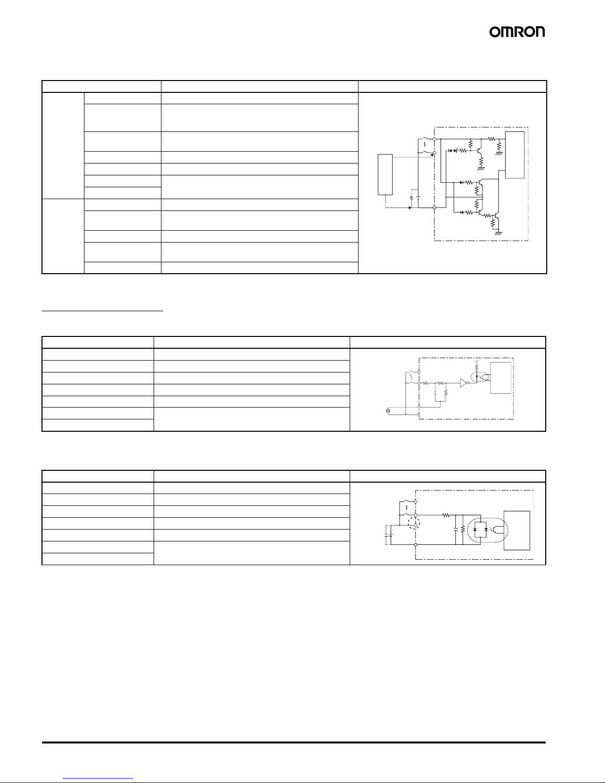
■ Input Specifications
CPU Units
AC Inputs (Not Isolated)
Note: Can be selected using the filter settings.
DC Inputs: I0 to I3 for Units with 10 I/O points, I0 to I9 for Units with 20 I/O Points (Not Isolated)
Note: Can be selected using the input filter settings, except when I0 is being used for an 8-digit counter with a high-speed input.
Item Specification
Safety standards cULus: UL508/CSA C22.2 No.142 Class I Div2
Conforms to EN/IEC 61131-2 clause 11, excluding 11.7.2.2 (Overvoltage category 2 and Pollution degree II
conforms to IEC 60664-1)
EMC
(See note.)
Radiation Field Emission CISPR11 Class A, Group 1
Noise Terminal Voltage Emission CISPR11 Class A, Group 1
Electrostatic Discharge Immunity IEC61000-4-2 In air: 8 kV, In contact: 6 kV
Electromagnetic Field Immunity IEC61000-4-3 10 V/m
Electrical Fast Transient/Burst Immunity IEC61000-4-4 Power line
AC I/O: 2 kV
DC I/O: 1 kV
Surge Immunity IEC61000-4-5 Normal Noise
AC power supply, AC I/O: 1 kV
DC power supply, DC I/O: 0.5 kV
Common Noise
AC power supply, AC I/O: 2 kV
DC power supply: 1 kV
DC I/O: 0.5 kV
Immunity to Conducted Disturbances Induced by Radio-frequency Fields
IEC61000-4-6 3 V
Momentary Power Interruption Immunity IEC61131-2 CPU Units with AC Power Supplies:
10 ms max.
CPU Units with DC Power Supplies:
2 ms max. (level: PS1)
Item Specifications Circuit drawing
Input voltage 100 to 240 VAC +10%,
−15%, 50/60 Hz
Input impedance 680 k
Ω
Input current 0.15 mA/100 VAC, 0.35 mA/240 VAC
ON voltage 80 VAC min.
OFF voltage 25 VAC max.
ON response time 50 ms or 70 ms at 100 VAC (See note.)
100 ms or 120 ms at 240 VAC (See note.)
OFF response time
Item Specifications Circuit drawing
Input voltage 12 to 24 VDC +20%,
−10%
Input impedance 5.3 k
Ω
Input current 4.5 mA (typ.)/24 VDC
ON voltage 8 VDC min.
OFF voltage 5 VDC max.
ON response time 15 ms or 50 ms (See note.)
OFF response time
100 to 240 VAC
N
L
IN
IN
330 kΩ 300 kΩ
51 kΩ
Internal
circuit
12 to 24 VDC
5.1 kΩ 1.8 kΩ
IN
IN
COM
Internal
circuit
10 Programmable Relay ZEN V2 Units
DC Inputs: I4 and I5 for Units with 10 I/O points, Ia and Ib for Units with 20 I/O Points
(Not Isolated)
Note: Can be selected using the input filter settings.
Expansion I/O Units
AC Inputs (Not Isolated)
Note: Can be selected using the input filter settings.
DC Inputs (ZEN-8E1DR: Not Isolated, ZEN-8E1DT: Photocoupler Isolated)
Note: 1. Can be selected using the input filter settings.
2. The ZEN-8E1DT has no +/- terminals. There is no need to supply power.
Item Specifications Circuit drawing
DC Inputs Input voltage 12 to 24 VDC +20%,
−10%
Input impedance PNP: 5.5 k
Ω/14 VDC min.
100 k
Ω/14 VDC max.
NPN: 5.2 k
Ω
Input current PNP: 4.3 mA (typ.)/24 VDC
NPN: 4.6 mA (typ.)/24 VDC
ON voltage 8 VDC min.
OFF voltage 3 VDC max.
ON response time 15 ms or 50 ms (See note.)
OFF response time
Analog
Inputs
Input range 0 to 10 V
External input
impedance
100 k
Ω min.
Resolution 0.1 V (1/100 FS)
Accuracy
±1.5% FS (at ambient operating temperature within
rated range)
AD conversion data 0 to 10.5 V (in increments of 0.1 V)
12 to 24 VDC
IN
COM
6.2 kΩ
220 kΩ
5.6 kΩ
150 kΩ
47 kΩ
47 kΩ
27 kΩ
−
+
Internal
circuit
Analog voltage
output device
Item Specifications Circuit drawing
Input voltage 100 to 240 VAC +10%,
−15%, 50/60 Hz
Input impedance 680 k
Ω
Input current 0.15 mA/100 VAC, 0.35 mA/240 VAC
ON voltage 80 VAC min.
OFF voltage 25 VAC max.
ON response time 50 ms or 70 ms at 100 VAC (See note.)
100 ms or 120 ms at 240 VAC (See note.)
Off response time
Item Specifications Circuit drawing
Input voltage 12 to 24 VDC +20%,
−10%
Input impedance 6.5 k
Ω
Input current 3.7 mA (typ.)/24 VDC
ON voltage 8 VDC min.
OFF voltage 5 VDC max.
ON response time 15 ms or 50 ms (See note 1.)
OFF response time
IN
IN
100 to
240 VAC
N
L
330 kΩ
51 kΩ
300 kΩ
Internal
circuit
12 to
24 VDC
6.2 kΩ
(See
note 2.)
1.8 kΩ
IN
IN
±
COM
Internal
circuit
Programmable Relay ZEN V2 Units 11
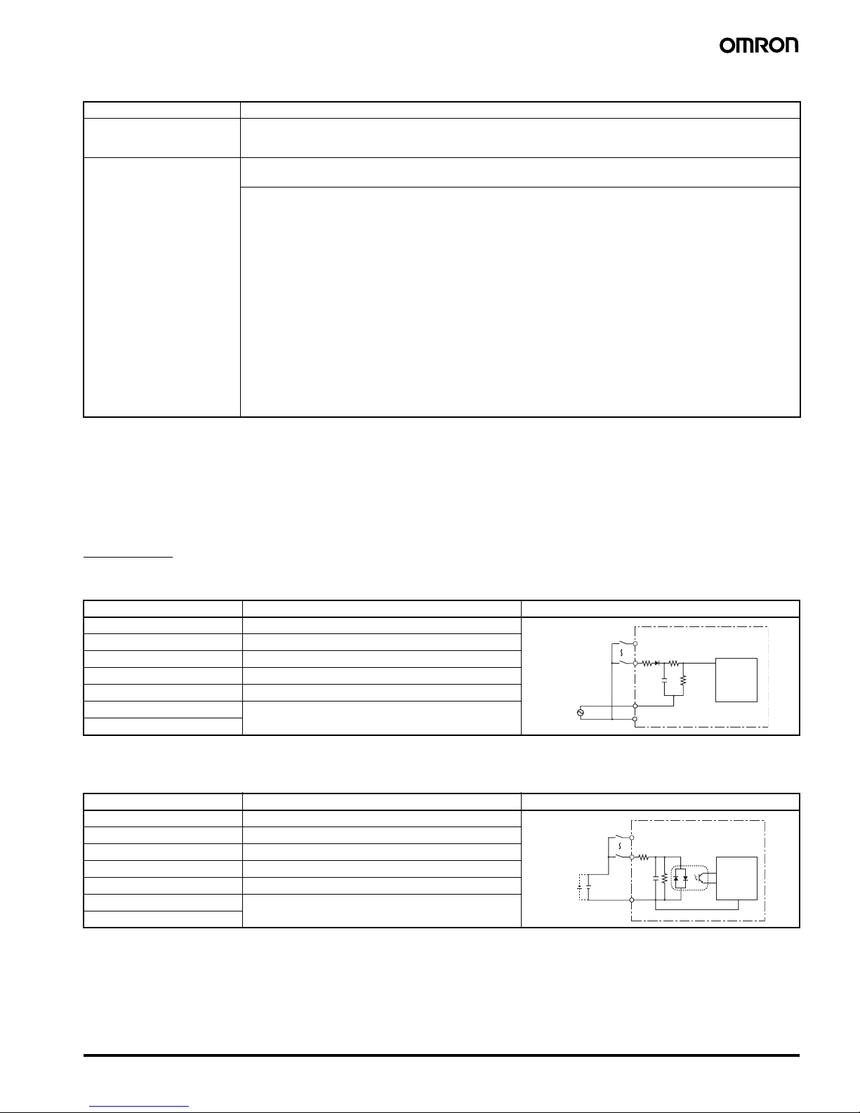
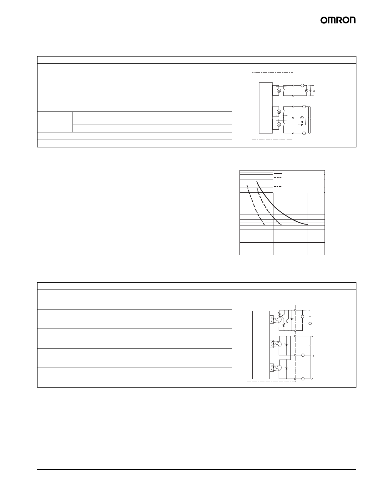
■ Output Specifications (CPU Units and Expansion I/O Units)
Units with Relay Outputs
Units with Transistor Outputs
Item Specifications Circuit drawing
Maximum switching capacity 250 VAC/8 A (resistive load: cos
φ = 1)
24 VDC/5 A (resistive load)
Use the following values for the total of all outputs.
CPU Units with 10 I/O points: 20 A max.
(15 A max. for Communications-type CPU Units)
CPU Units with 20 I/O points: 40 A max.
Expansion I/O Units: 20 A max.
Minimum switching capacity 5 VDC/10 mA (resistive load)
Relay life Electrical Resistive load: 50,000 times (cos
φ = 1)
Inductive load: 50,000 times (cos
φ = 0.4)
Mechanical 10 million times
ON response time 15 ms max.
OFF response time 5 ms max.
Item Specifications Circuit drawing
Maximum switching capacity 24 VDC +20%, 500 mA Each circuit is configured with an independent common
circuit
Leakage current 0.1 mA max.
Residual voltage 1.5 V max.
ON response time 1 ms max.
OFF response time 1 ms max.
Q0 to Q3/OUT0 to OUT3
Q4/Q6
COM
Q5/Q7
Models with
20 I/O points
only
L
L
L
Internal
circuit
1,000
300
100
10
02 4 6 810
Contact current (A)
30
50
500
250-VAC resistive load
24-VDC resistive load/
250-VAC inductive load
24-VDC inductive load
(t = 7 ms)
Life (× 10
3
)
The life under the worst conditions, of the output contacts used in
ZEN relay outputs is given in the above table. Guidelines for the
normal life of the relays are shown in the diagram on the right.
Life-test Curve (Reference Value)
Usage: 360 times/hour
Note: The switching capacity, switching durability, and applicable
load area when actually using the relay depend on the type of
load, environmental conditions, and switching conditions.
Therefore, be sure to confirm these conditions for the actual
machine before use.
Q0 to Q3/OUT0 to OUT3
Models with
20 I/O points
only
390 Ω
COM
Q4/Q6
Q5/Q7
28.8 VDC max.
28.8 VDC max.
L
L
L
L
1 kΩ
+
Internal
circuit
 Loading...