

Page 1
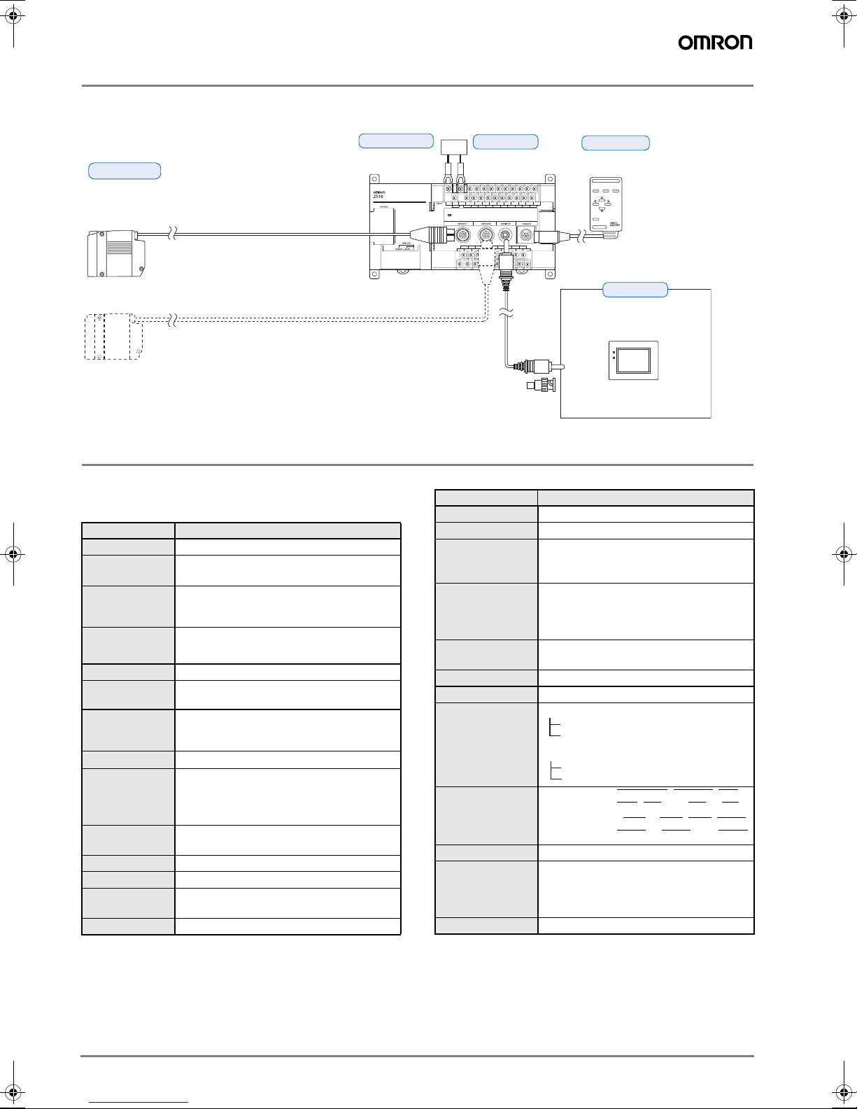
Welding Bead Sensor
Flatness OK ( 0/ 201) Last
Step
Depth:Bead :
Gap
Flatness
PEAK-BTM
Length
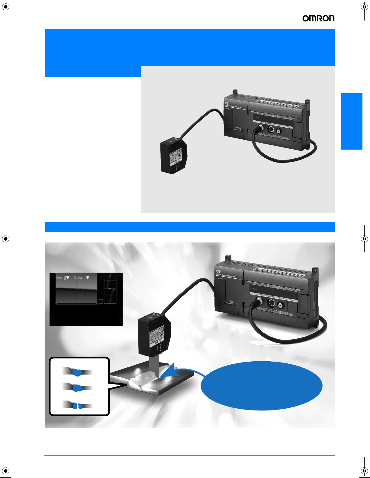
Z510
• Inspect for welding flaws by measuring the bead shape.
• Accumulate and output the profile data. Greatly simplify the management
of welding bead quality.
• The high-speed 10-ms measurement
period allows 100% in-line inspection.
• Automatic light intensity (brightness)
adjustment provides stable measurement of fluctuating metal surfaces.
• The compact sensor head contains
both the transmitter and receiver, so
mounting space is not an issue.
In-line Inspection of Welding Beads
Z510
Improve quality by performing 100% inspection of weld strength uniformity.
Display the Inspection Results or 3D Shape Data
Detect Various Bead Flaws
Flatness OK ( 0/ 201) Last
Step
:
Depth:Bead :
Gap
Flatness
PEAK-BTM
Length
ESC: Back SFT + ENT/ESC : Save/Load
−0000. 51846 mm PASS
−0000. 33351 mm PASS
:
+0000. 24302 mm PASS
:
−0000. 23053 mm PASS
:
+0000. 50820 mm PASS
:
+0000. 25458 mm PASS
Bead shape
Cracks or pinholes
Gaps in the weld
Features
Wide laser beam for
fast, highly accurate
inspections
B-53Z510
Page 2
Basic System Configuration
g
Sensors
Z510-SW2T (0.5-m cable)
Z510-SW6 (0.5-m cable)
Z510-SW17 (0.5-m cable)
Sensor Extension Cables
Z519-SCIR (1.5 m, 3 m, 6 m, 8 m, 13 m, or 18 m)
Specify the required cable length when ordering.
Up to 2 Sensors can be connected.
Specifications
Controllers:
Z510-WC10E and Z510-WC15E
General Specifications
Item Specification
Supply voltage 21.6 to 26.4 VDC
Current
consumption
Insulation
resistance
Dielectric
strength
Leakage current 10 mA max.
Noise resistance
Vibration
resistance
Shock resistance
Ambient
temperature
Ambient
humidity
Atmosphere No corrosive gases
Grounding
Degree of
protection
Material Case: ABS
1 A max. (with 2 Sensors connected)
20 MΩ min. (at 100 V DC) between DC exter-
nal terminals and GR terminal
(with internal surge absorber removed)
1,000 VAC, 50/60 Hz between DC external terminals and GR terminal (with internal surge
absorber removed)
1,500 V
P-P; pulse width: 0.1 µs/1 µs; rising
edge: 1-ns pulse
10 to 150 Hz (double amplitude of 0.1 mm)
for 8 minutes each in the X, Y, and Z directions
2
200 m/s
3 times each in 6 directions
Operating: 0 to 50°C (with no icing or condensation)
Storage: -15 to 60°C (with no icing or condensation)
Operating and storage: 35% to 85% (with no
condensation)
Less than 100 Ω
IEC60529 IP20 (In-panel)
Controllers
Z510-WC10E
Z510-WC15E
F150-VM
Monitor Cable (2 m)
Power supply
BNC Jack
(Included with the F150-VM)
Console
Z300-KP
(2-m cable)
ESC TRIG
ENT
SHIFT
CONSOLE
Monitors
F150-M05L
Color Liquid Crystal Monitor
(pin input)
POWER
SYNC
Use the Monitor to check
the image and display
menus when making
Characteristics
Item Specification
Number of Sensors Up to 2 Sensors can be connected.
Number of scenes 16
Light intensity
tracking function
Automatic (The light intensity tracking
range can be specified.)
Fixed (Select one of 31 stages.)
Select one of the following 6 items:
Measurement
items
Deviation from reference surface, Bead
height, Width, Bead change, Peak/Bottom,
Inspection length
Region
specification
A region can be specified in the direction of
the line beam.
Data storage 2,048 points max.
Trigger function Free-run, External 1, External 2, or Auto
• Judgement output
RS-232C output
Terminal block output
Results output
Terminal block
• Measurement value output
(measurement value)
RS-232C output
output
Analo
8 input points: TRIGGER
, LD-OFF, RE-
SET, DI0, and DI4 to DI7
12 output points:DO0 to DO5, DO8, DO15,
to DO19, and GATE
DO17
Monitor interface 1 channel (for pin jack or overscan monitor)
The full-scale output can be divided into
Analog output
resolution
40,000 gradations max.
Resolution (See note.): 0.25 mV (± 5 V)
0.4 µA (4 to 20 mA)
Weight Approx. 700 g (Controller only)
Note: This resolution is for measurements with an OMRON K3AS Linear Sen-
sor Controller connected and values averaged over 64 measurements.
B-54 Displacement sensors / Width-measuring Sensors
Page 3

Sensors: Z510-SW2T, Z510-SW6, and Z510-SW17
Sensor model Z510-SW2T Z510-SW6 Z510-SW17
Mirror reflection Diffuse
reflection
Measurement mode
Diffuse
reflection
Mirror reflection Diffuse
reflection
Mirror reflection
Measurement distance at center
20 mm (16 mm with
beam cover mounted)
5.2 mm 50 mm 44 mm 100 mm 94 mm
Measurement range ±0.8 mm ±5 mm ±4 mm ±20 mm ±16 mm
Light source
Visible semiconductor laser
(Wavelength: 670 nm, 15 mW
Visible semiconductor laser
(Wavelength: 658 nm, 15 mW max., class 3B)
max., class 3B)
Beam dimensions (See note 1.)
Linearity
20 µm × 4 mm typical at the reference distance
(2-mm measurement region)
±0.1% F.S.
(See note 2.)
±0.1% F.S.
(See note 3.)
30 µm × 24 mm typical at the ref-
erence distance
(6-mm measurement region)
±0.1% F.S. (See note 4.)
60 µm × 45 mm typical at the ref-
erence distance
(17-mm measurement region)
Resolution 0.25 µm (See notes 5 and 6.) 0.3 µm (See notes 7 and 8.) 1 µm (See notes 7 and 8.)
Sampling period 9.94 ms
LED indicator (Laser indicator) Lit when the laser is ON.
Temperature characteristic
0.01% F.S./° C
(See note 9.)
Degree of protec-
IP64 IP66
tion
Environmental resistance
Ambient operating illumination
Ambient temperature
Illumination at light-receiver surface: 3,000 lx max. (incandescent light)
Operating: 0 to 50°C (with no icing or condensation)
Storage: -15 to 60°C (with no icing or condensation)
Ambient humidity Operating and storage: 35% to 85% (with no condensation)
Vibration (de-
10 to 150 Hz (double amplitude of 0.35 mm) for 8 minutes each in the X, Y, and Z directions
struction)
Controller: Die-cast aluminum
Materials
Cable sheathing: Heat-resistant PVC
Connector: Zinc alloy and brass
Cable length 0.5 m
Minimum bending radius 68 mm
Weight Approx. 350 g Approx. 600 g
Z510
Note: 1. The minimum light intensity at the edges of the beam is defined as 1/e2 (13.5%) of the intensity at the center of the beam. Some light will
scatter beyond this beam region and the measurement may be affected if the immediate vicinity around the workpiece is highly reflective.
2. This is the error with respect to the theoretical line of the displacement output when measuring the standard OMRON quartz glass. The
linearity may vary depending on the workpiece being used.
3. This is the error with respect to the theoretical line of the displacement output when measuring a standard OMRON stainless-steel block.
The linearity may vary depending on the workpiece being used.
4. This is the error with respect to the theoretical line of the displacement output when mea-
suring the standard OMRON white alumina ceramic. The linearity may vary depending on
the workpiece being used.
5. This is the displacement output’s peak-to-peak displacement conversion value. These fig-
ures are for measurement of the standard OMRON quartz glass (mirror reflection) or standard OMRON stainless-steel block (diffuse reflection) at the center of the measurement
region. The resolution performance characteristics may not be met when operating in a
magnetic field.
6. These figures are for Sensors connected to a Z510-WC10E or Z510-WC15E and averaged over 16 measurements. The averaged data
was transmitted to a PC through an RS-232C connection for storage and processing.
7. This is the displacement output’s peak-to-peak displacement conversion value. (These figures are for measurement of the standard OM-
RON white alumina ceramic at the center of the measurement region.)
The resolution performance characteristics may not be met when operating in a strong magnetic field.
8. These figures are for Sensors connected to a Z510-WC10E or Z510-WC15E and averaged over 64 measurements. The averaged data
was transmitted to a PC through an RS-232C connection for storage and calculations.
9. This is the value measured when the gap between the Sensor and workpiece (white alumina ceramic) is fixed with an aluminum jig.
Z510-SW17
120 mm
Digital output
80 mm
80 mm
±0.1% max.
120 mm
Distance
B-55Z510
Page 4

ALL DIMENSIONS SHOWN ARE IN MILLIMETERS.
To convert millimeters into inches, multiply by 0.03937. To convert grams into ounces, multiply by 0.03527.
Cat. No. Q03E-EN-02
In the interest of product improvement, specifications are subject to change without notice.
B-56 Displacement sensors / Width-measuring Sensors
 Loading...