

Page 1
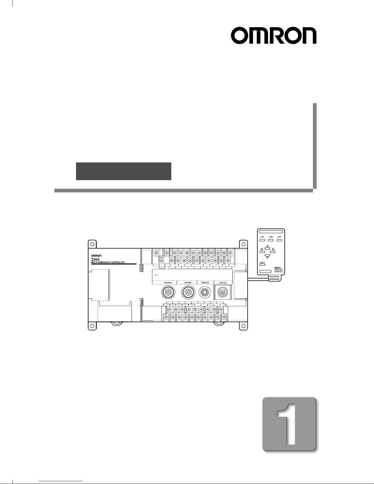
Multi-Dimensional Controller
Multi-Dimensional Controller
Z500
Setup Manual
Cat. No. Z158-E1-1
Manual
Page 2

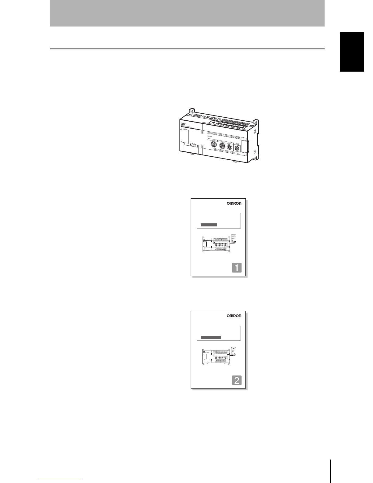
About this Manual
Please read the following manuals carefully and be sure you understand the information provided
before attempting to install or operate the Z500.
Manual 1: Setup Manual
Multi-Dimensional Controller
Multi-Dimensional Controller
Z500
Setup Manual
Manual
Cat. No. Z000-E1-1
Cat. No. Z158-E1-1
Manual 2: Operation Manual
Installation
This manual describes the hardware for the Z500
(Multi-Dimensional Controller) and how to install the
components.
Be sure to read this manual first.
Wiring
Multi-Dimensional Controller
Z500
Operation Manual
Manual
Cat. No. Z000-E1-1
Cat. No. Z159-E1-1
Starting the Z500
and Positioning
the Workpiece
Adjusting Images
Setting
Measurement
Conditions
and Executing
SECTION 2 Basic Operations
This section describes how to start the Z500
and how to display images on the monitor.
SECTION 3
Menus for Conversational Menu
• Basic settings required for measurement
• Measurement of consistent workpieces
Menus for Conversational Menu
Settings can be made easily by entering
information as requested - just as
though you are having a conversation
with the Z500.
SECTION 4 Menus for Expert Menu
• Customized settings
• Detailed settings
• Measurement of workpieces placed at different
positions
Menus for Expert Menu
More detailed setting, such as position
compensation for workpieces placed at
different positions, can be made.
Outputting to
External Devices
SECTION 7 I/O Format
This section provides details on the inputs and outputs
used for communications with external devices via
terminal blocks or RS-232C.
• Communications settings
• I/O format
• Timing for communications
Page 3

Multi-Dimensional Controller
Z500
Z500-MC10
Setup Manual
INTRODUCTION 3
SECTION 1
Wiring and Connection
SECTION 2
Installation
SECTION 3
Connecting External Devices
SECTION 4
Troubleshooting and Maintenan ce
INTRODUCTION
SECTION 1 SECTION 2 SECTION 3 SECTION 4
17
25
39
51
Manual
1
Page 4

Special or Crit ica l Applica tio n s
When the Z500 will be us ed in one o f the conditions or application s listed below, allow extra safety
margins in ratings and functions, add extra safety feature such as fail-safe systems, and consult your
OMRON representative.
• Operating conditions or environments which are not described in the manual
• Nuclear power control systems, railroad systems, aviation systems, vehicles, combustion systems,
medical equipment, amusem ent equipment, or safety equipment
• Other sys tems, machines, and equipment that may have a serious influence on lives and property and
require extra safety features
Product Availability
Some of the products listed may not be available in some countries. Please contact your nearest
OMRON sales office by referring to the addresses provided at the back of this manual.
© OMRON, 2002
All right s reserved. No part of this public ation may be reproduc ed, stored in a retriev al syst em, or transmi tted, in any
form, or by any means , mechanical, ele ctronic, photoc opying, reco rding, or other wise, without the prior wr itten
permission of OMRON.
No patent liability is assumed with respect to the use of the information contained herein. Moreover, because
OMRO N is co nstantly striving to improve its h igh-quality products, the information contained in this manual is subject
to change without notice. Every precaut ion ha s been taken in the pre paration of this manual. Nevertheless, OMRON
assumes no responsibility for errors or omissions. Neither is any liability assumed for damages resulting from the use
of the information contained in this publication.
Z500
2
Setup Manual
Page 5

INTRODUCTION
Table of Contents
INTRODUCTION.................................................................................... 3
INTRODUCTION
Table of Contents..........................................................................................................3
Precautions on Safety..................................................................................................4
Laser Safety............................. ..... .. ....... ..... .. .......... .. ..... ....... ..... ....... .. ..... ....... ..... .. ....... .5
Export of the Products .................................................................................................9
Caution.........................................................................................................................10
Notice...........................................................................................................................11
Confirming Package Contents................................................... ..... .. ....... ..... ..... .. ......15
Editor's Note................................................................................................................16
SECTION 1
Wiring and Connection...................................................................... 17
1-1 Basic System Configuration..............................................................................18
1-2 Component Names and Functions ...................................................................20
1-3 Power Supply and Ground.................................................................................22
SECTION 2
Table of Contents
Installation .......................................................................................... 25
2-1 Mounting the Controller.....................................................................................26
2-2 Mounting the Sensor..........................................................................................28
SECTION 3
Connecting External Devices............................................................ 39
3-1 Terminal Block Connections.............................................................................40
3-2 RS-232C Connections........................................................................................44
3-3 Linear Sensor Controller Connections.............................................................46
SECTION 4
Troubleshooting and Maintenance................................................... 51
4-1 Troubleshooting .................................................................................................52
4-2 Maintenance........................................................................................................54
4-3 Specifications and Dimensions .........................................................................55
Z500
Setup Manual
3
Page 6
INTRODUCTION
INTRODUCTION
Precaution on Safety
OMRON products are manufactured for use according to proper procedures by a qualified operator and
only for the purposes described in this manual.
Precaution on Safe ty
The following conventions are used to indicate and classify precaut ions in this manual. Always heed the
information provided with them. Failure to heed precautions can result in injury to people or damage to
property.
DANGER
WARNING
CAUTION
Indicates an imminently hazardous situation which, if not avoided, will result in death or
seriou s in jury.
Indicates a potentially hazardous situation which, if not avoided, could result in death or
seriou s in jury.
Indica tes a potential ly hazar dous s ituation which, if not a voided, may re sult in m inor or
moderate in jury, or pr operty d amage .
WARNING Fa ilure to read and understand the information pro vided in this manual may result in
personal injury or death, damage to the product, or product failure. Please read
each section in its entirety and be sure you understand the information provided in
the section and related sections before attempting any of the procedures or operations given.
Z500
4
Setup Manual
Page 7
INTRODUCTION
Laser Safety
This manual uses the followin g signs and s y mb o ls to ensure safe operation of the Z500.
These signs and symbols are important for avoiding injury to people or damage to the product. Be sure
to pay attent ion t o t hem.
Their meanings are given below.
Warning
INTRODUCTION
Laser Safety
WARNING
Indic at e s an im m in ently ha zardous si tuation whic h , if no t
avoided, will result in death or serious injury.
Signs and Symbols
Laser Beam Hazard
Caution s to In di ca te Potenti al La se r B ea m H az ard
Safety precautions for using laser equipment
WARNING
Do not to expose your eyes to the laser radiation either directly or
indirectly (i.e., after reflection from a mirror or shiny surface).
The laser radiation has a high power density and exposure may
result in loss of sight.
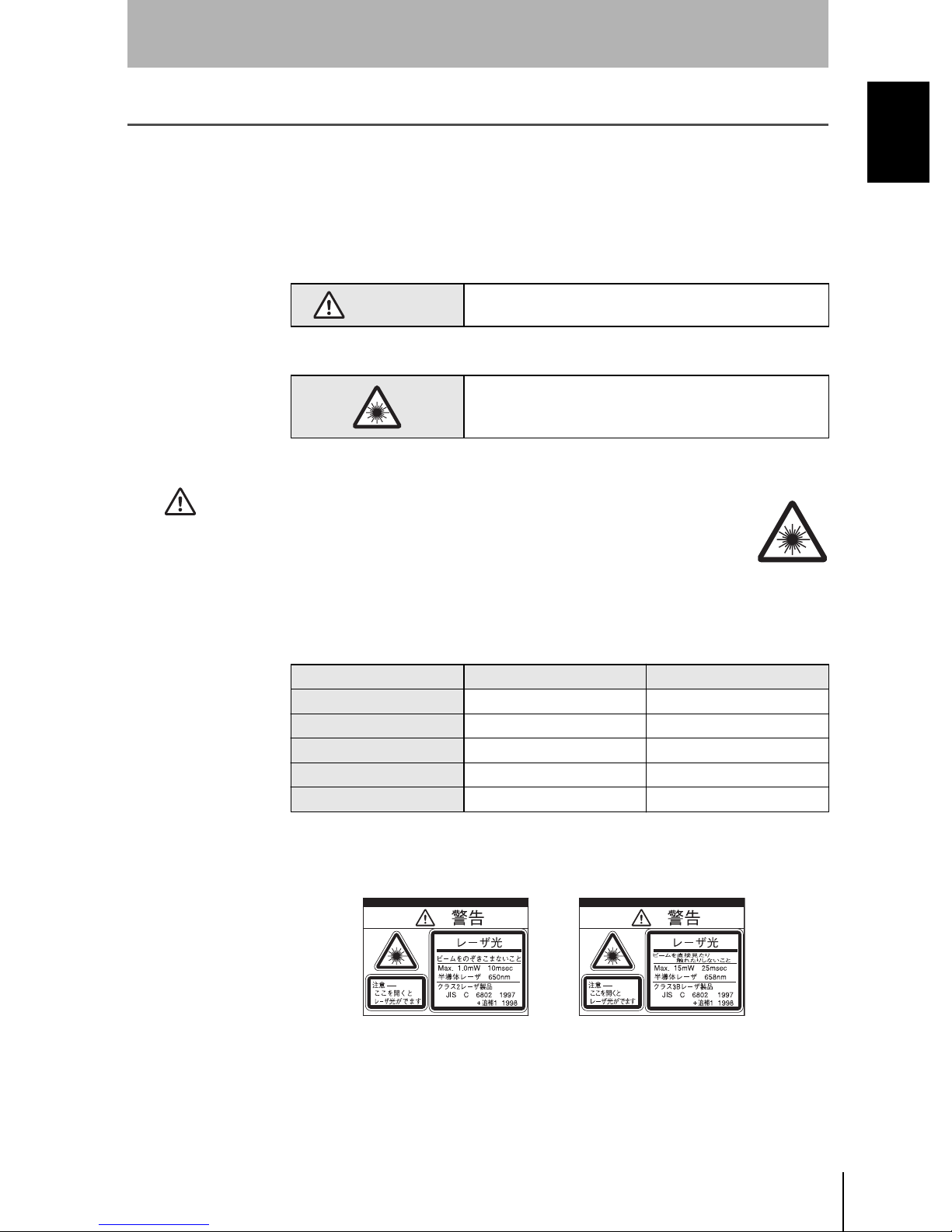
The Z500 series uses laser as the light source and is classified as shown below
according to the IEC standard (IEC60825-1).
Wavelength 650 nm 658 nm
Maxi mum pulse dura tion 10 ms 17.5 ms
Cycle 0.5 to 10 ms 0.5 to 25 ms
Peak power 1 mW max. 15 mW max.
Class 23B
Z500-SW2 Z500-SW17
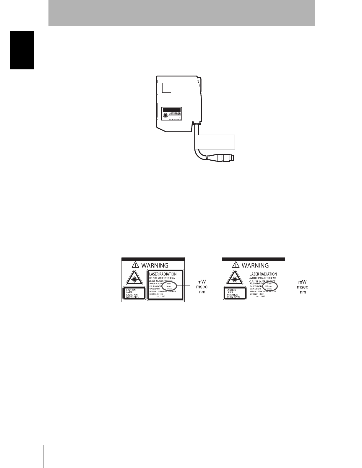
Labeling on Laser Use
The Z500 has, on the side of its sensor, a warning label as shown below.
Z500-SW2 Z500-SW17
Z500
Setup Manual
5
Page 8

INTRODUCTION
INTRODUCTION
Safety Device
The Z500 is equipped with laser radiation warning lamp and laser off input
circuit. Interlocking unit can be configured in the external circuit.
Laser Safety
Unle ss th e produ ct is in Run Mode, however, laser off input from the external
circuit is disabled. This ensures stable measurement. Be sure to use lasershielding safety goggles when installing or adjusting Z500-SW17.
Safety Instructions
• Use laser enclosure device to prevent specular object from reflecting laser
beam.
When used without an enclosure, be sure to avoid a laser path from eye level.
• Safe distance (Nominal Optical Hazard Distance: NOHD) is approximately 1
m; it is advisable, however, to terminate the laser on its path if possible. Nonreflective, flatting material is recommendable for termination.
• Be sure to use laser-shielding safety goggles when installing or adjusting
Z500-SW17.
Outline of IEC60825 Standard
The following are the safety measures to be taken by the user for each type of
laser equipment.
Classification
Requirements
Remote interlock Not required
Key control Not required
Beam attenuator Not required
Emission
indicator device
Warning signs Not required
Beam pa th
Specular
reflection
Eye protection Not required
Protective
clothing
Training Not required
* With respect to the requirements of remote interlock connector, key control, beam
attenuator, and emission indicator, Class 3B laser products no t exceedin g f iv e t i mes
the AEL of Cla ss 2 in t he wave length r an ge of 400 nm to 700 nm are to be treated as
Class 3A laser products.
Class 1 Class 2 Clas s 3A Class 3B* Class 4
Connect to room or door
circuits
Remove key when not in
use
When in use preve n t s
inadve r te nt exp os ure
Not required
Not
required
Not required
Not required
Terminate bea m at e nd of us e ful leng th
Required for all operator and
mainte nance pe r s onnel
Indicates laser is
energized
Follow precautions on
warnin g si gns
Prevent unintentional
reflections
Required if engineering
and admi ni strati v e proc edures n ot prac ti ca bl e an d
MPE exceeded
Sometimes
required
Specific
requireme nts
Z500
6
Setup Manual
Page 9
Re-labeling
CAUTION
Use in the U.S.
INTRODUCTION
Two di fferent labels are provided, to be used selectively according to countries.
• for use in the U.S.: FDA label
• for use in countries other than the U.S.: Warning label
Be sure to turn off the sensor before replacing the label, or your hand or other
body p arts ma y be expose d to th e haza rdous l aser b eam ra diatin g from the
sensor.
When a laser product mounted on a certain device is to be used in the U.S., it has
to meet the requirements set forth by the FDA (regulations for laser products set
forth by the Food and Drug Administration). Three different FDA labels are
enclosed in the package. Attach them to the sensor body.
Applic ati o ns h ave been app roved by CD RH (C enter fo r De vi ce s and Rad iol o gical
Health) for Z500-SW17. Z500-SW2 should not be used in the U.S. at this
moment since the application for this model has not been approved yet.
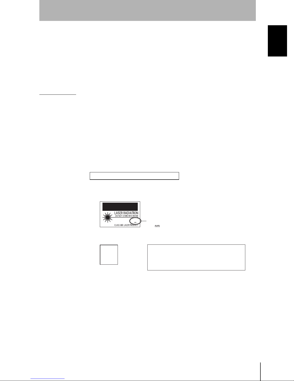
FDA Labels for Laser Products
The Z500 is designed to be bu ilt into the finished sys tem unit. Refer to the
following technical standard for installation.
INTRODUCTION
Laser Safety
21CFR1040.10 and 1040.11
FDA Labels
lass III B Caution logo type
CAUTION
µw
15000
PEAK POWER
PULSE DURATION
WAVE LENGTH
Z500-SW17
Aperture Label Certification and Identification Label
AVOID
EXPOSURE
Laser radiation
is emitted from
this aperture
Be sure to attach FDA la be ls; do n ot att ac h En gl ish WARNING labels by mistake .
15000
25000
658
µw
µs
25000
µs
658
This laser product complies with
21 CFR 1040.10 and 1040.11.
OMRON Corporation
Shiokoji Horikawa, Shimogyo-ku,
Kyoto 600-8530 JAPAN
Place of manufacture:
AYABE Factory, OMRON Corp.
Manufactured in
Z500
Setup Manual
7
Page 10
INTRODUCTION
CAUTION
INTRODUCTION
Areas to Attach Labels
Z500-SW17
Laser Safety
AVOID
EXPOSURE
Laser radiation
is emitted from
this aperture
CAUTION
Class III B
PEAK POWER
PULSE DURATION
WAVE LENGTH
µw
15000
µs
25000
658
Certification and
Identification Label
This laser product complies with
21 CFR 1040.10 and 1040.11.
OMRON Corporation
Shiokoji Horikawa, Shimogyo-ku,
Kyoto 600-8530 JAPAN
Place of manufacture:
AYABE Factory, OMRON Corp.
Manufactured in
Caution logo type
Use in Countries Other than the U.S.
Replace the warning label in Japanese on the sensor main body with the
attached English one upon use in countries other than the U.S. Attach the label
in the area where the original Japanese warning label was provided.
European EN60825-1 standard is applied to products exported to European
countries. The Z500 conforms to the standard.
Aperture Label
Warni ng Labels
1.0
10
650
15
25
658
Z500-SW17Z500-SW2
Z500
8
Setup Manual
Page 11

INTRODUCTION
Export of the Products
Z500-SW2 is considered as special freight under the Foreign Exchange and Foreign Trade Laws and
theref ore requ ires a lice nse for ex port. As for other coun tries, o bserve the laws spec ified by each
country.
INTRODUCTION
Export of the Products
Z500
Setup Manual
9
Page 12
INTRODUCTION
INTRODUCTION
Caution
Installation Environment Precautions
CAUTION
Caution
CAUTION
Do not use the Z500 in environments with flammable or explosive gases.
Install the Z500 away from high-voltage devices and moving machinery to a llow
safe access during operation and maintenance.
Power Supply and Wiring Precautions
CAUTION
CAUTION
CAUTION
CAUTION Confirm that wiring has been performed correctly before turning ON the power
CAUTION
CAUTION
Use the Z500 with the power supply voltages specified in this manual.
Use crimp terminals for wiring. Do not connect the power supply wires by just
twisting stranded wire and connecting directly to the terminals.
Use the wire and crimp terminals of the p roper sizes as specified in this manual.
supply.
Cover the terminal blocks with the Terminal Block Protection Covers.
Uncovered terminal blocks can result in electric shock.
Use a DC power supply with countermeasures against high-voltage spikes (safe
extra low-voltage circuits on the secondary side).
CAUTION
Other Precautions
CAUTION
CAUTION
Be sure to securely tighten the screws when mounting the Z500.
Do not attempt to dismantle, repair, or modify the Z500.
Dispose of the Z500 as industrial waste.
Z500
10
Setup Manual
Page 13
INTRODUCTION
Notice
The Z500 is highly reliabl e and resis tant to most environmen t factor s. The followi ng guidel ines, however,
must be followed to ensure reliability and opti m u m use of th e Z500.
Installation of the Controller
INTRODUCTION
Notice
Installation Site
Do not install the Z500 in locations subjected to the following conditions:
• Ambient temperature outside of 0 to +50 ºC
• Condensation due to rapid temperature fluctuations
• Relativ e humidities outside 35 to 85%
• Corrosive or flammable gases
• Dust, salt, or iron particles
• Direct vib ration or shock
• Reflection of intense light
(such as other laser beams or electric arc-welding machine)
• Strong magnetic fields
• Direct sunlight
• Water, oil, or chemical fumes or spray
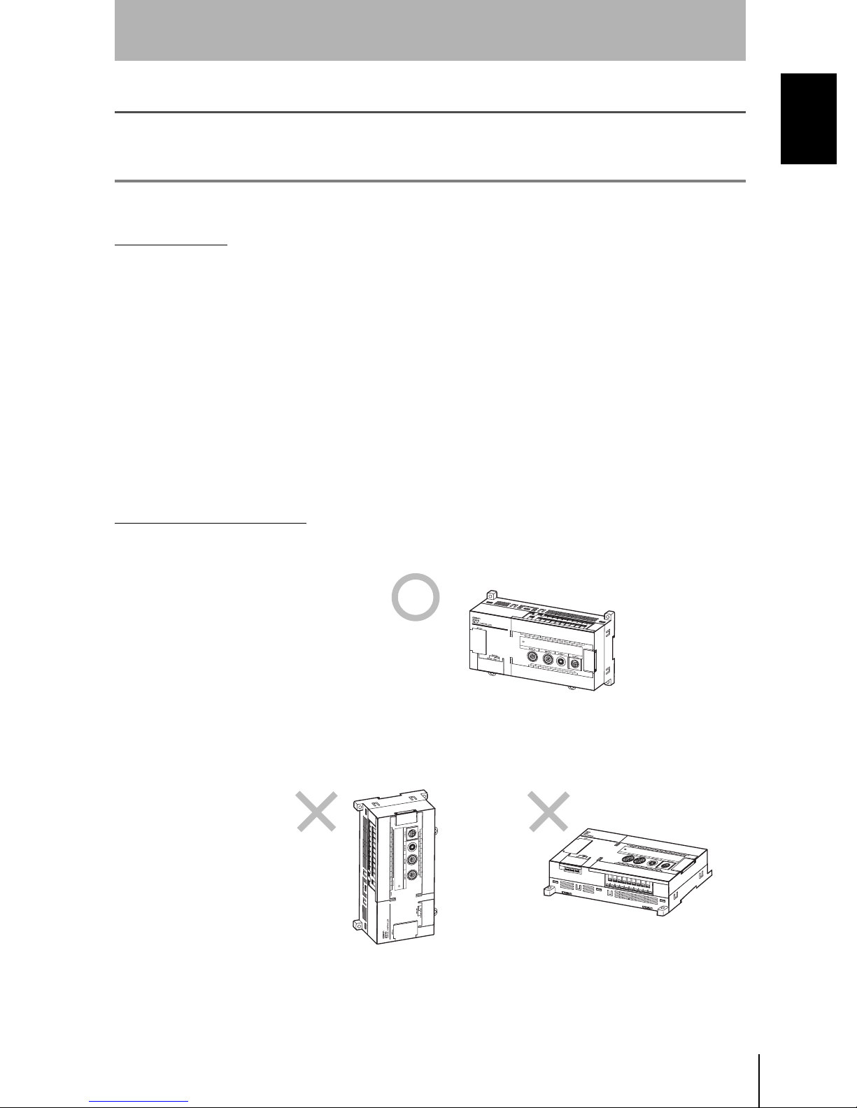
Mounti ng of the Controller
To im pr ove heat d issipat io n, install the C ontro ller in th e follo wing di re ction only:
CORRECT
Do not install the Controller in the orientations shown in the following diagram.
INCORRECT
Z500
Setup Manual
11
Page 14
INTRODUCTION
2
INTRODUCTION
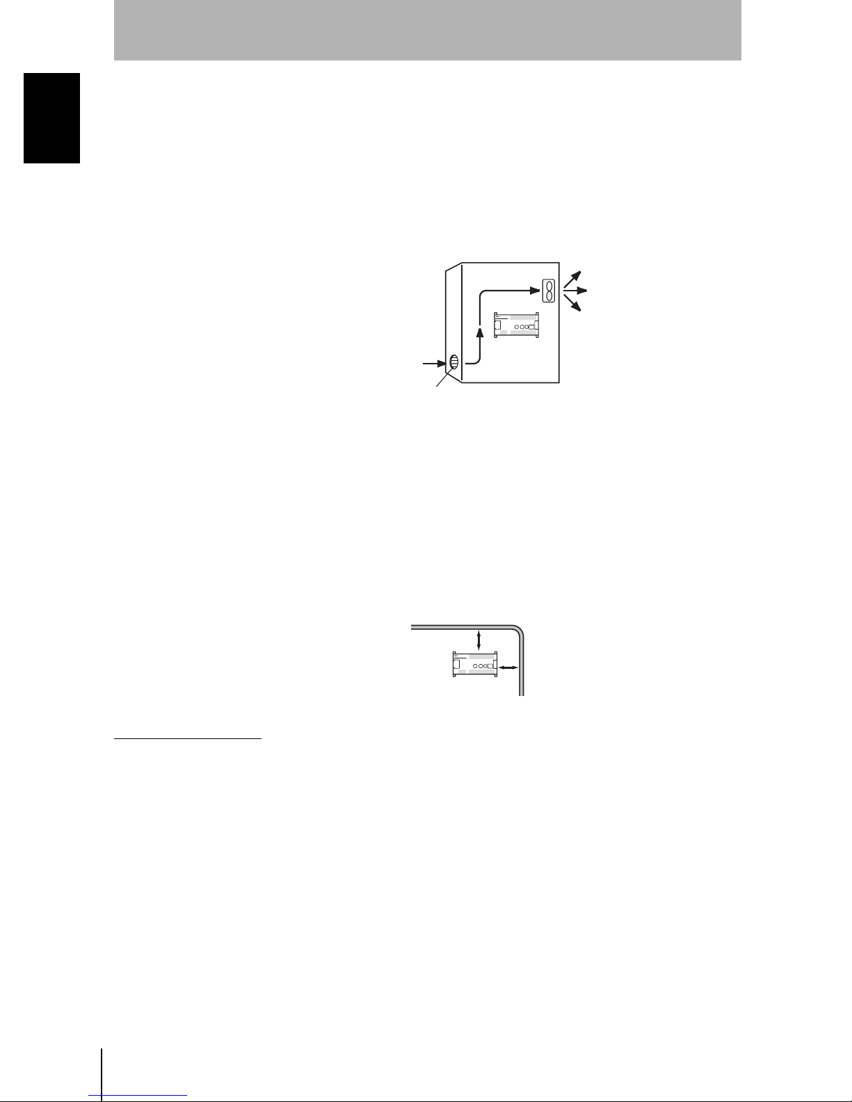
Ambient temperature
• Maintain a minimum clearance of 50 mm above and below the Z500 to
improve air circulation.
Notice
• Do not install the Z500 immediately above significant heat sources, such as
heaters, transformers, or large-capacity resistors.
• Do not let the ambient temperature exceed 50 ºC.
• Provide a fo rc ed-air fan co o ling or air conditioning if the ambient temperature
is near 50 ºC so that the ambient temperature never exceeds 50 ºC.
Control panel
Z500
Z500
ouver
Sensor Maintenance
Ambient Illumination
• Do not let the ambient illumination exceed 3000lx.
• When using the Z500 near lighting equipment that turns ON and OFF
continuously, reduce the influence of the light by, for example, using a light
baffle.
Noise resistance
• Do not install the Z500 in a cabinet containing high-voltage equipment.
• Do not install the Z500 within 200 mm of power cables.
Power cable
00 mm min.
Z500
200 mm min.
Z500
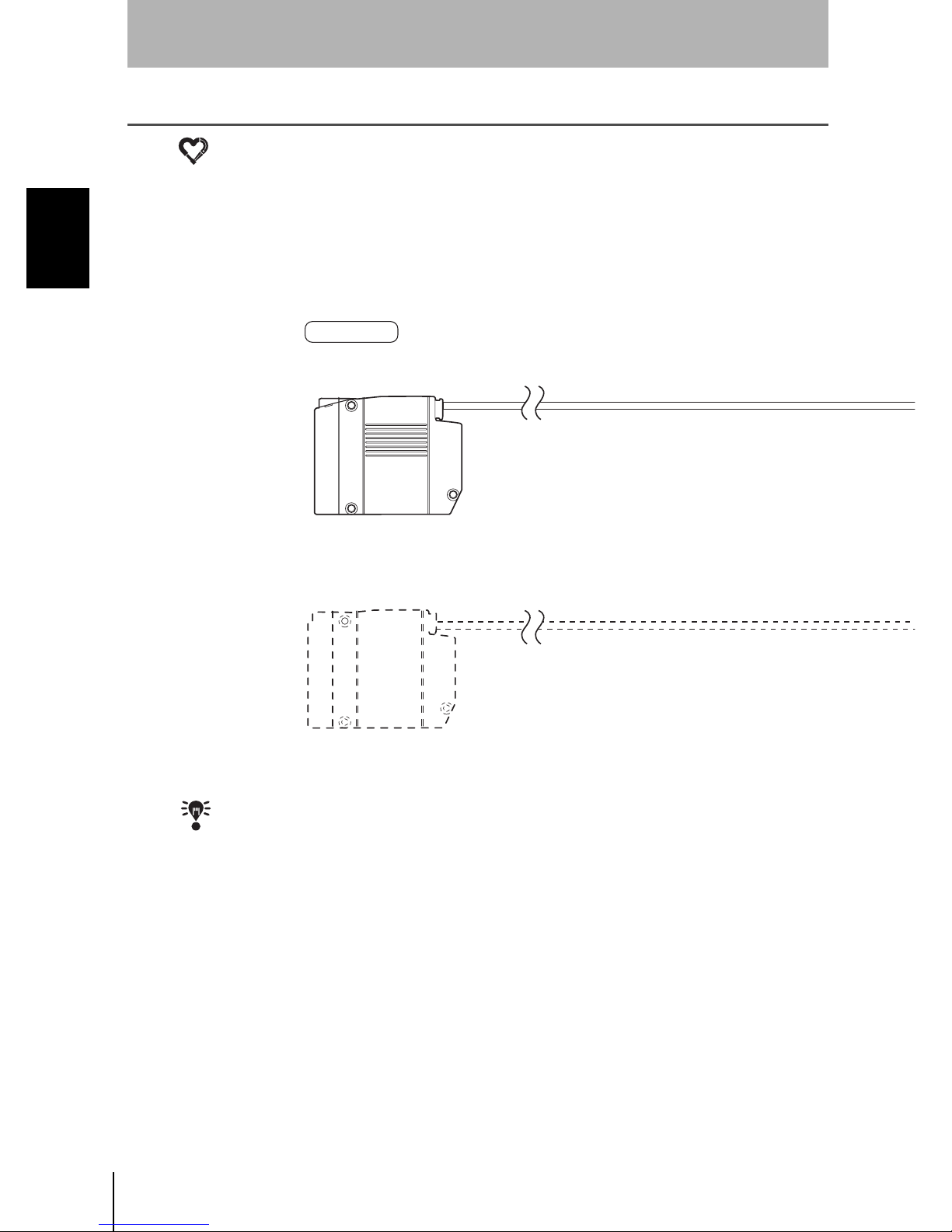
Install the Sensor in a clean environment and keep the filter on the front panel of
the Sensor free from oil and dust. If affected by oil or dust, clean the filter as
follows:
• Use a blower brush (used to clean camera lenses) to blow large dust particles
from th e surfac e. Do not blo w the dust a way wit h your mouth.
• Use a soft cloth (for lenses) with a small amount of alcohol to remove the
remaining dust. Do not use a scrubbing action when cleanin g as scratches on
the f ilter c ou ld result in the S e nsor m a l func tioning.
Environment
The Sensor cannot accurately detect the following types of objects:
* Objects with an extremely low reflection ratio
* Objects with a small curvature
* Largely inclined objects
Z500
12
Setup Manual
Page 15
Component Installation and Handling
INTRODUCTION
INTRODUCTION
Components
The Sensor and Console must be products designed specifically for the Z500.
• Sensor (Z500-SW2 and Z500-SW17)
• Console (Z300-KP)
Connecting Cables
Always turn OFF the Z500's power before connecting or disconnecting cable.
Touching Signal Lines in Connectors or Terminals
To prevent damage from static electricity, use a wrist strap or another de vice for
preventing electrostatic discharges when touching terminals or signal lines in
connectors.
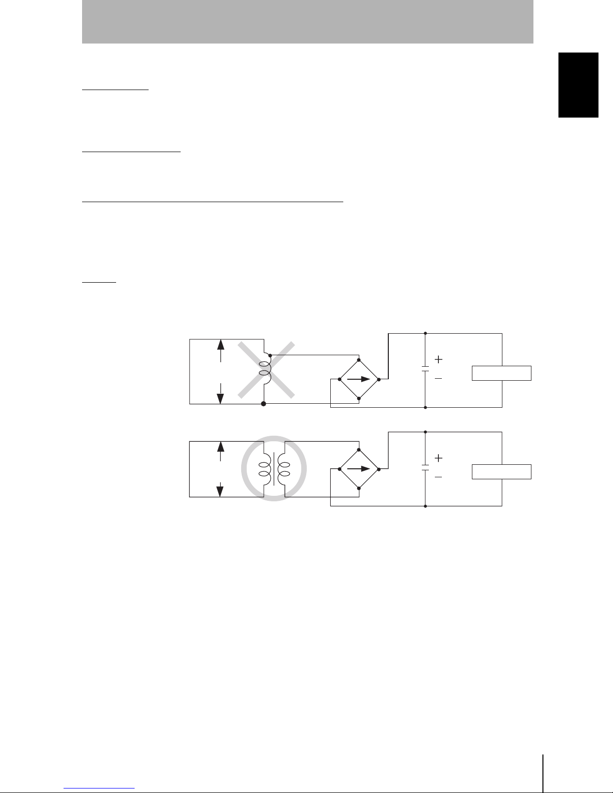
Wiring
When using a transformer for the Z500's driving power supply, use an isolation
transformer in the way shown below. Do not use an auto-transformer. Doing so
may result in equipment failure.
Auto-transformer
Commercial
power supply
Notice
Z500-MC10
Isolation transformer
Commercial
power supply
Z500-MC10
Z500
Setup Manual
13
Page 16

INTRODUCTION
INTRODUCTION
Turning OFF the Power
Do not turn OFF the power while a message is being displayed indicating that
processing is being performed. Data in memory will be destroyed, and the Z500
Notice
may not operate correctly the next time it is started.
Scn 0
Saving
Save
Using the RESET Signal
Do not input the RESET input immediately after power is turned ON. When
using the RESET input to synchronize startup timing, wait at least 1 second after
the Z500's power supply is turned ON before turning ON the RESET terminal.
Securing the Video Monitor (When Using the Recommended F150-M09)
If the video monitor case is metallic, observe the following precautions to
prevent noise interference, because the video monitor case is connected to the
0V line in the internal circuits.
• Do not ground the video monitor.
• Do not ground the metallic part of the connector.
• Secure the video monitor with plastic screws if it is being mounted to a
meta llic su rface.
Warming Up
After tu rn in g
before use. The circuits are unstable immediately after the power supply is
turne d ON and attem pting me as ure me nt may res ult in inconsist ent measuremen t
values.
Z500
14
Setup Manual
ON the power
supply, allow the Z500 to stand for at least 30 minutes
Page 17
INTRODUCTION
Confirmi ng Package C ontents
Check the contents of the package as soon as you receive the Z500.
It is e xtremely rare for co m ponents to be missi ng, but contact the nearest OMRON representative if any
of the following items are missing.
Z500 Controller. . . . . . . . . . . . . . . . . . . . . . . . . . Qty: 1
Manual 1: Setup Manual (This Manual) . . . . . . Qty: 1
INTRODUCTION
Confirming Package Contents
Multi-Dimensional Controller
Multi-Dimensional Controller
Z500
Setup Manual
Manual
Cat. No. Z000-E1-1
Manual 2: Operation Manual . . . . . . . . . . . . . . . Qty: 1
Multi-Dimensional Controller
Z500
Operation Manual
Manual
Cat. No. Z000-E1-1
Z500
Setup Manual
15
Page 18

INTRODUCTION
INTRODUCTION
Editor's Note
Visual Aids
Editor's Note
NOTICE Indicates information required to take full advantage of the functions and perfor-
CHECK
REFERENCE
HELP
The following headings appear in the left column of the manual to help you
locate different types of information.
mance of the product. Incorrect application methods may result in the loss or
damage to the product. Read and follow all precautionary information.
Indicates points that are important in using product functions or in application
procedures.
Indicates where to find related information.
Indicates information helpful in operation.
OMRON Product References
All OMRON products are capitalized in this manual. The word "Unit" is also capitalized when it refers to an OMRON product, regardless of whether or not it
appears in the proper name of the product.
Z500
16
Setup Manual
Page 19

Z500
Setup Manual
SECTION 1
Wiring and Connection
1-1 Basic System Configuration 18
1-2 Component Names and Functions 20
1-3 Power Supply and Ground 22
SECTION 1 Wiring an d C on nec ti on
17
Page 20
SECTION 1
Wiring and Connection
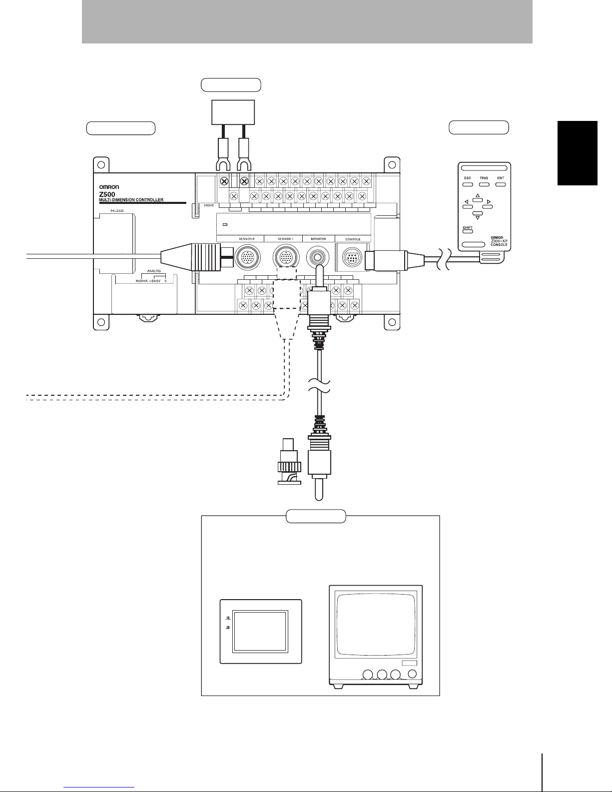
1-1 Bas i c Syst em Co n fig ur at io n
SECTION 1
1-1 Basic System Configuration
NOTICE
• The following dia gram shows the basic Z500 system configuration. Some of the
components shown in the configuration diagram are special OMRON products that cannot
be substituted with comparable de v ices. Thes e items a re in dicated with an asterisk.
• Always turn OFF the power supply before connecting or disconnecting cables. The
peripheral devic e m ay be da maged if connected or disco nnected with the power supp ly
turned ON.
Sensor
Z500-SW2 (2-m cable)
Z500-SW17 (2-m cable)
* Sensor Extension Cable
Z309-SC1 (3 m, 8 m, or 13 m)
Specify the required cable length when ordering.
CHECK
Up to 2 S en sors can be connec t ed .
Z500
18
Setup Manual
Page 21
SECTION 1
Wiring and Connection
Controller
Z500-MC10
Power Supply
Recommended model:
OMRON S82K-05024
F150-VM Monitor Cable (2 m)
Console
*
Z300-KP
(2-m cable)
SECTION 1
1-1 Basic System Configuration
BNC Jack
(included with
the F150-VM)
Monitors
F150-M05L
Color Liquid
Crystal Monitor (pin input)
The Monitor is used to check the image and display menu where making settings.
F150-M09
Monochrome
CRT Video Monitor
(BNC input)
Z500
Setup Manual
19
Page 22

SECTION 1
Wiring and Connection
1-2 Component Names and Functions
1-2-1 Sensor
SECTION 1
1-2 Component Names and Functions
Z500-SW2
Z500-SW17
1. LASER indicators
6. Beam cover
5. Monitor
2. Emitter
4. Light
3. Receiver
2. Emitter
1. LASER indicators
3. Receiver
1. Provides laser beam warning indicators.
• For 15 to 25 seconds after the pow er supply i s tur ned O N, both indicators
will be OFF indicating that the laser beam is OFF.
• When the laser beam turns ON, both indicators will light.
• When the laser beam turns OFF, both indicators will turn OFF.
2. Emits laser beam.
3. Receives laser beam.
4. Light used when displaying surrounding images.
5. Captures surrounding images.
6. Used for switching between display of surrounding images and measurement.
To display surrounding images, move the beam cover lever to the left. To
perform measurement, move the lever to the right.
CHECK
CHECK
Tighten the le ver screw s with a flat- b laded scr e wd river to a torque in the range 0.15 to 0.3
N·m (1.5 to 3 kgf·cm).
When Using the Z500-SW2
• When performing measurement with the beam cover removed, attach the monitor cap
provid ed wit h the Se nso r ove r the Li gh t and Mon it or i n t he wa y sho wn o n th e n ext page .
• When displaying surrounding images, be sure to attach the beam cover. Surrounding
images cannot be displayed correctly without the beam cover attached.
Z500
20
Setup Manual
Display of
surrounding images
Move the beam cover
lever to the left.
Measurement
Move the beam cover
lever to the right.
Page 23

SECTION 1
Wiring and Connection
1-2-2 Controller
Z500-MC10
Z500
MULTI-DIMENSION CONTROLLER
POWER
17.
indicator
RS-232C
16.
connector
Beam cover attached
Lever screws:
M2 × 5
wo, M2 × 4
7. Ground terminal 9. Output terminals
8. Power Supply
terminals
10. Input terminals
Beam cover removed
Monitor cap
(provided as an accessory)
SECTION 1
1-2 Component Names and Functions
11. Monitor connector
Do not remove the
sticker on the side.
14. Analog output
terminals
Shading indicates parts that are lifted to see the terminals underneath.
9. Output terminals
Do not open.
12. Console connector13. Sensor connectors15. DIP switch
7. Connected to the ground wire.
8. Connected to the power supply.
9. Connected to external devices such as a PLC.
10. Connected to external devices such as a PLC.
11 Connected to the monitor.
12. Connected to a console.
13. Connected to the sensor.
14. Connected when using analog output.
15. Do not use. (Turn OFF the DIP switch.)
16. Connected to external devices such as a personal computer or PLC.
17. Lit while power is ON.
Z500
Setup Manual
21
Page 24

SECTION 1
SECTION 1
Wiring and Connection
1-3 Power Supply and Ground
Wire the power supply and the ground to their respective terminals. Tighten the screws to a torque of
between 0.5 and 0.6 N
m. After wiring, confirm that the wiring is correct.
·
1-3 Power Supply and Ground
NOTICE
Re-cover the terminal blocks with the Terminal Block Protection Covers.
Unco ve red terminal b loc k s can resul t in el ec t ric s ho ck.
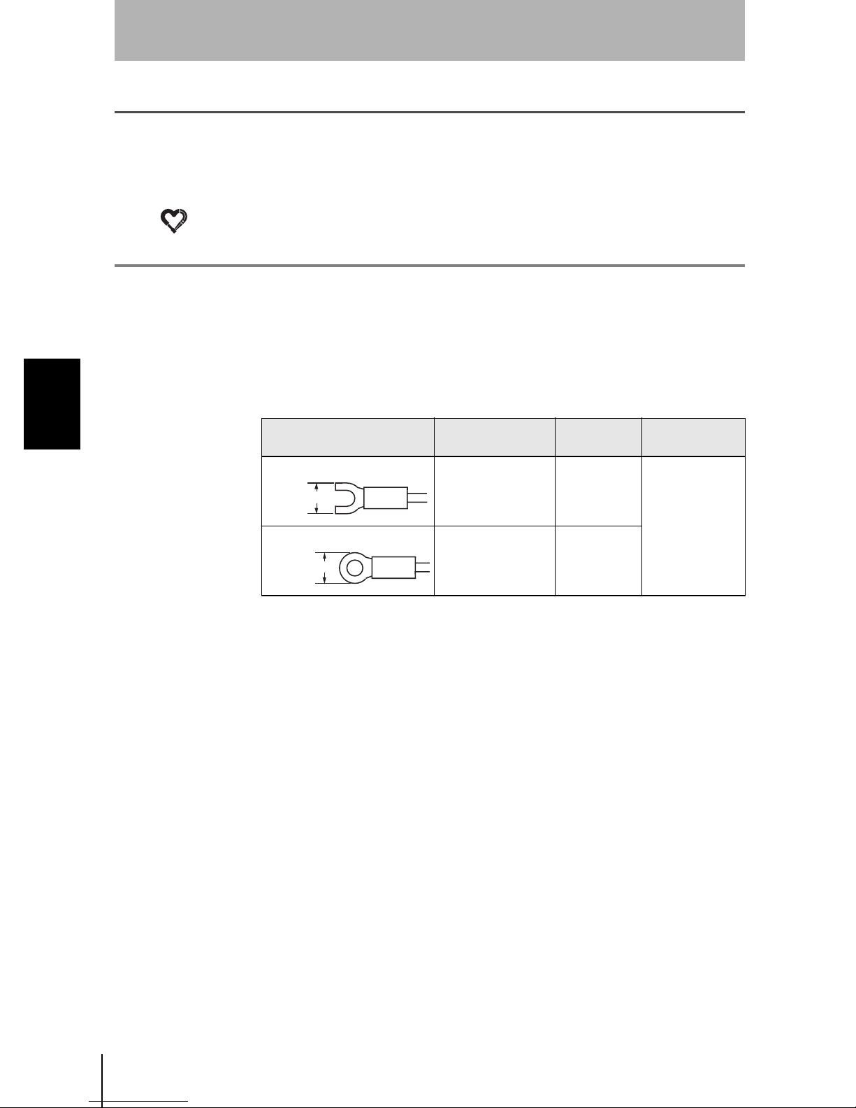
1-3-1 Cr i mp Te rminals a nd Cables
The terminal block uses M3 terminal screws.
Use appr opriate cri mp terminals for M 3 screws as show n b elow.
Recommended Crimp Terminals
Type Manufacturer Model
Forked
6.2 mm max.
Round
6.2 mm max.
1-3-2 Ground Wiring
J.S.T. Mfg Co., Ltd. V1.25-N3A
J.S.T. Mfg Co., Ltd. V1.25-MS3
Recommended
wire size
1.31 to 1.65 mm
2
To avoid grounding problems, do not share the ground wire with any other
devices or wire the ground to the building's steel framing. Always connect a
ground wire to the Z500's ground terminal.
Use a grounding point that is as close as possible and keep the ground wiring as
short as possible.
×× × × × × × × × × × ×
×
Ground to 100 Ω
or less.
× × × × × × ×
POWER
× × ×
DI1 DI2 DI4 DI6
DI1 DI3 DI5 DI7
Z500
22
Setup Manual
Page 25

1-3-3 Wiring the Power Supply
Wire the Power Supply Unit independently of other devices. In particular, keep
the power supply wired separately from inductive l oads.
Use a power supply that meets the following specifications.
Recommended Power Supply
Output current Power supply voltage
1.6 A min. 24 VDC (21.6 to 26.4VDC)
Recommended Model
Manufacturer Model
OMRON Corp. S82K-05024
SECTION 1
Wiring and Connection
SECTION 1
1-3 Power Supply and Ground
CHECK
• Use a DC power supply with countermeasures against high-voltage spikes (safe extra
low-voltage circuits on the secondary side). Excessively high voltages can result in
electric shock.
• If UL recognition is required, use a UL class II power supply.
• Keep the power supply wiring as short as possible.
+
24 VDC
POWER
-
DI1 DI 2 DI 4 DI 6
DI1 DI3 DI 5 DI7
Z500
Setup Manual
23
Page 26

SECTION 1
1-3 Power Supply and Ground
SECTION 1
Wiring and Connection
MEMO
Z500
24
Setup Manual
Page 27

Z500
Setup Manual
SECTION 2
Installation
2-1 Mounting the Controller 26
2-2 Mounting the Sensor 28
SECTION 2 Installation
25
Page 28
SECTION 2
2-1 Mount ing the Controller
SECTION 2
Installation
2-1 Mounting the Controller
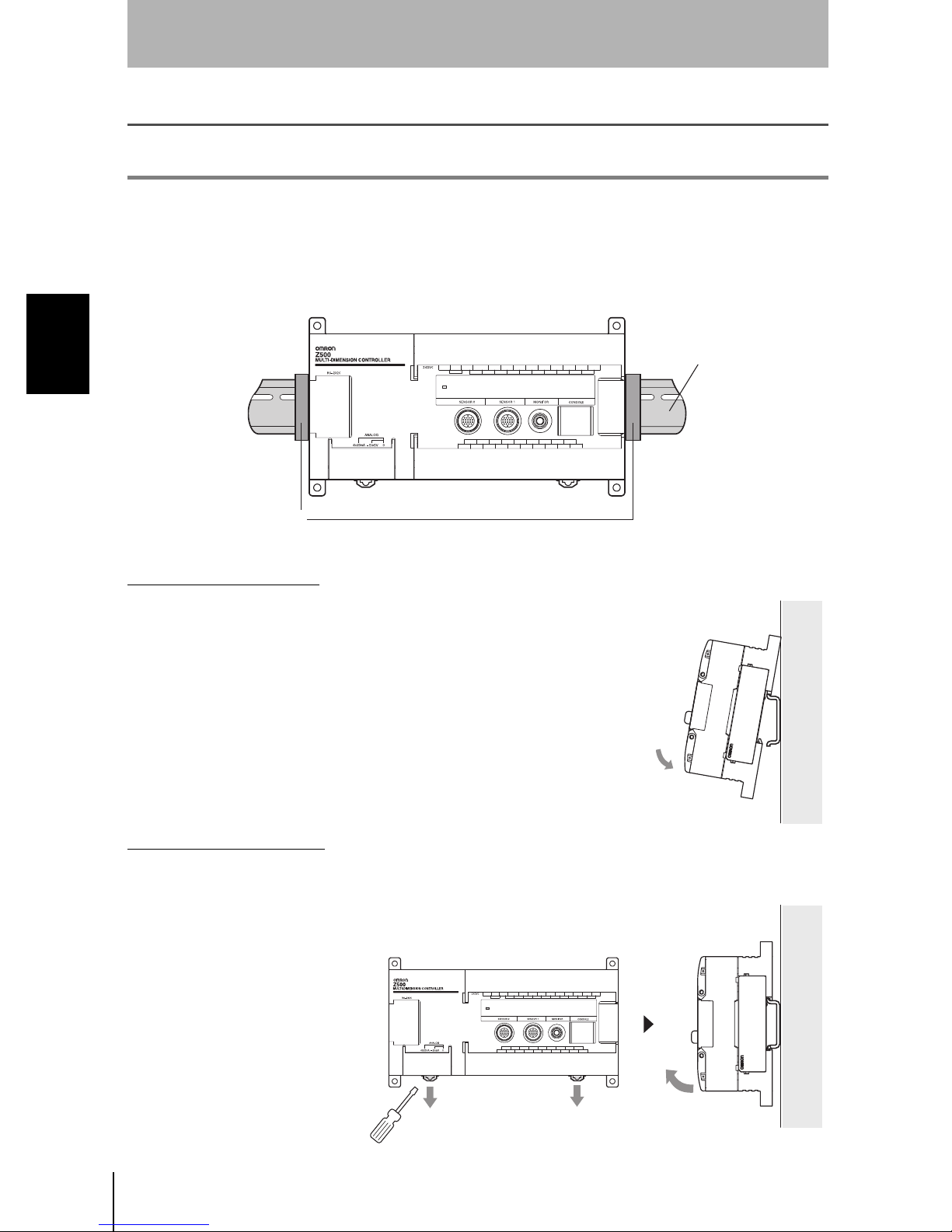
There are two ways to mount the Controller: DIN Track mounting or surface-mounting.
2-1-1 DIN Track Mounting
The Controller can be easily mounted to or removed from 35-mm DIN Track.
DIN Track
The following DIN Tracks are
available from OMRON.
PFP-100N (1 m)
PFP-50N (50 cm)
PFP-100N2 (1 m)
PFP-M
End Plate (OMRON)
Mounting the Controller
Hook the Controller into the DIN Track as shown in
the diagram and then press in at the bottom until
the Controller locks into place.
Removing the Controller
Use a flat-bladed screwdriver to pull the hook down and then pull out the
Controller from the bottom.
Z500
26
Setup Manual
Page 29

2-1-2 Surface Mounting
SECTION 2
Installation
Four, M4
100±0.2
185±0.2
(Unit: mm)
SECTION 2
2-1 Mount ing the Controller
8
Z500
Setup Manual
27
Page 30

SECTION 2
Installation
2-2 Mounting the Sensor
Up to 2 Sensors can be connected per Controller.
SECTION 2
2-2 Mount ing the Sensor
NOTICE
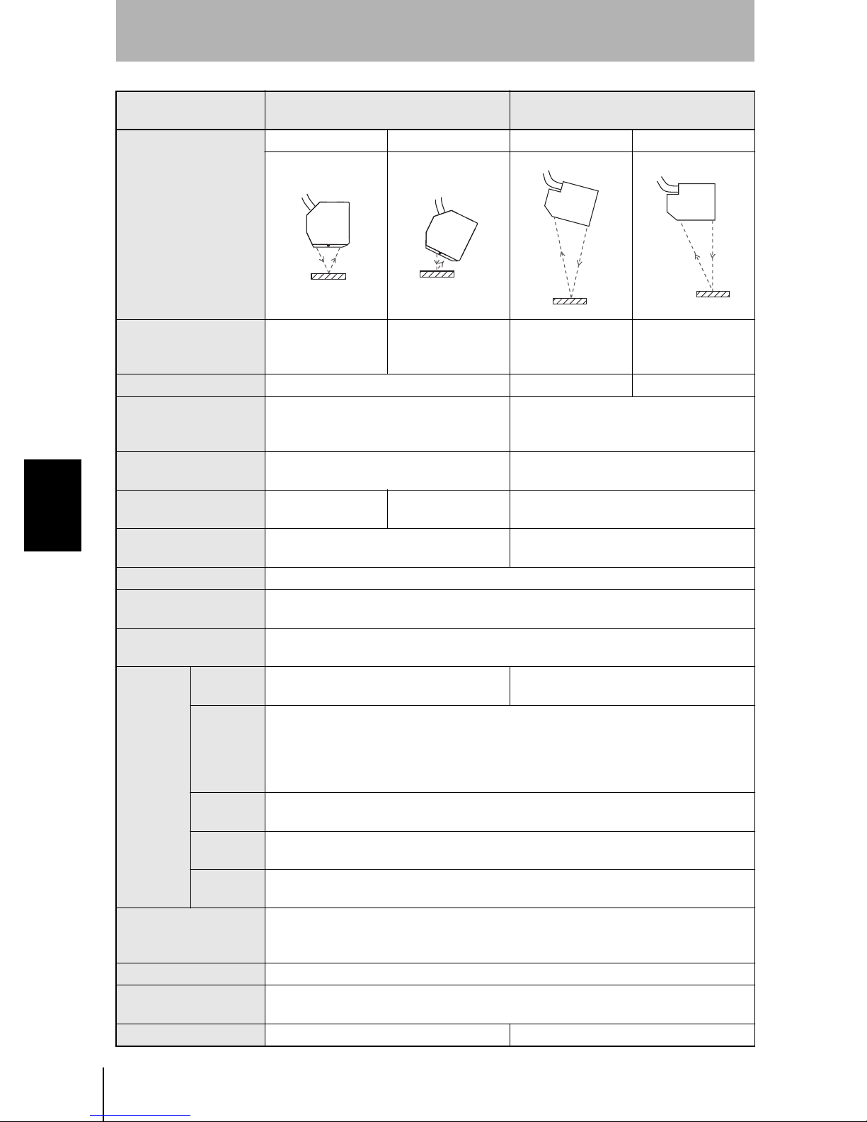
2-2-1 Sensor Types
Type
Super High-precision
Model
Z500-SW2
Long-range Model
Z500-SW17
measurement
Only co ntrollers de si gned s pecifi cally f or the Z500 can be used.
Using another type of controller may result in damage to the sensor or controller.
Distance to
Height
center (A)
20 mm ±0.8 mm
100 mm ±20 mm
(B)
Measurement range
Width
(D)
B= +0.8 mm : 4.0 mm
(The width of t he measurement
region is 2.2 mm.)
B= 0 mm : 4.0 mm
(The width of t he measurement
region is 2.3 mm.)
B= -0.8 mm : 4.0 mm
(The width of t he measurement
region is 2.4 mm.)
B= +20 mm : 40 mm
(The width of t he measurement
region is 14.5 mm.)
B= 0 mm : 45 mm
(The width of t he measurement
region is 17.3 mm.)
B= -20 mm : 50 mm
(The width of t he measurement
region is 20.1 mm.)
Spot diameter
(C)
B= +0.8 mm : 40 µm
B= 0 mm : 20 µm
B= -0.8 mm : 40 µm
B= +20 mm : 280 µm
B= 0 mm : 60 µm
B= -20 mm : 280 µm
CHECK
A
Dista nc e to m ea sureme nt center (A), Heig ht (B ) , Width (D) , and Spot diameter (C)
Front View
Z500-SW2
Line beam
+0.8mm
0mm
-0.8mm
D
B
C
+20mm
Z500-SW17
0mm
-20mm
Line beam
D
Z500
28
Setup Manual
Page 31

2-2-2 Measurement Range
Super High-precision Model: Z500-SW2
SECTION 2
Installation
CHECK
20mm
+0.8mm
0mm
-0.8mm
Relation betw een Measurement Mode and Measurement Range
Wide Mode
+0.8mm
0mm
0.8mm
2.2mm
(±1.1mm)
2.3mm
(±1.15mm)
2.4mm
(±1.2mm)
Measurement
range
+0.8mm
0mm
-0.8mm
SECTION 2
2-2 Mount ing the Sensor
Zoom Mode
0.73mm
0.76mm
0.80mm
Z500
Setup Manual
29
Page 32

SECTION 2
-
SECTION 2
Installation
Long-range Model: Z500-SW17
100mm
20mm
0mm
Measurement
range
2-2 Mount ing the Sensor
CHECK
-20mm
Relation betw een Measurement Mode and Measurement Range
Wide Mode
+20mm
0mm
20mm
14.5mm
(±7.25mm)
17.3mm
(±8.65mm)
20.1mm
(±10.05mm)
+20mm
0mm
20mm
Zoom Mode
4.8mm
5.7mm
6.7mm
Z500
30
Setup Manual
Page 33

2-2-3 Mounting Dimensions
Super High-precision Model: Z500-SW2
• Dimensions for Diffuse Reflection
SECTION 2
Installation
Reception axis
51.7±0.1
Mounting Holes
Two, M4
24.1±0.1
• Dimensions for Mirror Reflection
Reception axis
Measurement center
5.2 77.2
51.74.7
24.149.3
Measurement
78.4
center
13.8
Emission axis
Reference plane
Vinyl-insulated round cable 6.8 dia.
Standard length 2m
20
16
(4)
4
50
65
57
(Unit: mm)
SECTION 2
2-2 Mount ing the Sensor
Connector
(Unit: mm)
Two, 4.5-dia. holes
4
57±0.1
Mounting Holes
Two, M4
32
56.5
Emission axis
Reference plane
Vinyl-insulated round cable 6.8 dia.
Standard length 2m
18.1
25
25
20
20
65
Connector
Z500
Setup Manual
31
Page 34

SECTION 2
2-2 Mount ing the Sensor
SECTION 2
Installation
Long-range Model: Z500-SW17
• Dimensions for Diffuse Reflection
Measurement center
70±0.1
9.5±0.1
Three, M4
100
Emission axis
25
25
Reception axis
Reference plane
4
16.4
9.5
80
72
70
(Unit: mm)
Three, 4.5-dia. holes
25
100
69
69±0.1
Mounting Holes
• Dimensions for Mirror Reflection
Measurement center
Emission axis
37.7 15.6
68.3±0.1
24.2±0.1
Three,
M4
16.9
Vinyl-insulated round cable 6.8 dia.
Standard length 2m
94
9.3
24.2
12.5
25
Reception axis
Reference plane
95.9
68.3
45.1
Connector
(Unit: mm)
Three, 4.5-dia. holes
23.5
15.2
109.6
65.3
Mounting Holes
Z500
32
Setup Manual
65.3±0.1 15.2±0.1
Vinyl-insulated round cable 6.8 dia.
Standard length 2m
Connector
Page 35

2-2-4 Mounting Orientation
Mounting Near Walls
Errors will occur if light reflected off a wall surface is received by the Sensor.
If it is not possible to mount the Sensor away from the wall, mount in the way
shown below, i.e., so that the plane containing the emission axis and the
reception axis is parallel to the wall surface.
Also, applying matt black coating to the wall surface will help to reduce the
amount of light reflected.
SECTION 2
Installation
SECTION 2
2-2 Mount ing the Sensor
Narrow Grooves or Indentations
If measurement is performed in an indentation between two walls, or in a
groove, mount the Sensor in the way shown below, i.e., so that the path along
the emission and reception axes is not interrupted by a wall.
Z500
Setup Manual
33
Page 36

SECTION 2
2-2 Mount ing the Sensor
SECTION 2
Installation
Level Differences
When measuring w orkpieces with level differences, the i nfluence of the level
difference can be minimized by mounting the Sensor so that the plane containing
the emission axi s and th e reception axis is parallel to the boundary between the
different levels.
Rotating Workpieces
When measuring rotating workpieces, the influence of position displacement
and blurring of the rotating workpiece can be minimized by mounting the Sensor
so that the plane containing the emission axis and the reception axis is parallel
to the axis of rotation.
Z500
34
Setup Manual
Page 37

SECTION 2
Installation
Projections When measuring the tops of projections on the workpieces, mount the Sensor
so tha t the entire projection pas ses through the line beam.
Front View
Line beam
SECTION 2
2-2 Mount ing the Sensor
Z500
Setup Manual
35
Page 38

SECTION 2
2-2 Mount ing the Sensor
SECTION 2
Installation
2-2-5 Mounting Distance
After selecting the Sensor mounting status in the menu item Environment,
mount the Sensor in a location where the status can be measured correctly.
REFERENCE
Refer to page 146 in the Operation Manual.
Super High-precision Model: Z500-SW2
• Dimensions for Diffuse Reflection
50
• Dimensions for Mirror Reflection
mission axis
mission axis
Workpiece
Workpiece
25 25
Reception
axis
Reception axis
16±
0.8mm
5.2±0.8mm
*
±
0.8mm
20
Z500
36
Setup Manual
* Beam cover attached
Page 39

Long-range Model: Z500-SW17
• Dimensions for Diffuse Reflection
SECTION 2
Installation
SECTION 2
• Dimensions for Mirror Reflection
Reception
axis
2.5
Emission
axis
25
Workpiece
12.5 12.5
100±20mm
2-2 Mounting the Sensor
Reception
axis
Workpiece
Emission
axis
94±16mm
Z500
Setup Manual
37
Page 40

SECTION 2
2-2 Mounting the Sensor
SECTION 2
Installation
2-2-6 Mutual Interference
When using 2 or more Sensors mounted adjacently, make sure that the spots
(shown below) for other Sensors are outside the shaded areas.
Super High-precision Model: Z500-SW2
(Unit: mm)
Long-range Model: Z500-SW17
2.2
2.2
1.3
1.2
2.3
18.9
21.1
2
(Unit: mm)
Z500
38
Setup Manual
79 80
121
3
20
42
428
100
40
45
50
Page 41

Z500
Setup Manual
SECTION 3
Connecting External Devices
3-1 Terminal Block Connections 40
3-2 RS-232C Connections 44
3-3 Linear Sensor Controller Connections 46
SECTION 3 Connecting External Devices
39
Page 42
SECTION 3
Connecting External Devices
3-1 Terminal Block Connections
This section explains how to connect I/O to the Z500 through its terminal block to input signals such as
measurement commands or output signals suc h as measurement results.
Refer to the Operation manual for details on I/O formats.
SECTION 3
3-1 Terminal Block Connections
NOTICE
Re-cov er the t ermi na l bl oc ks wi th the Te rm inal Blo ck Pro t ecti on Cove r s. Uncove red te rminal bloc ks can result i n electr ic sho ck .
3-1-1 Cr i mp Te rminals a nd Cables
The terminal block uses M3 terminal screws.
Use appropriate crimp terminals for M3 screws as shown below. Tighten the
screws to a torque of between 0.5 and 0.6 N·m.
Recommended Crimp Terminals
Type Manufacturer Model
Forked
6.2 mm max.
Round
6.2 mm max.
J.S.T. Mfg Co., Ltd. V1.25-N3A
J.S.T. Mfg Co., Ltd. V1.25-MS3
Recommended
wire size
1.31 to 1.65 mm
2
Z500
40
Setup Manual
Page 43

3-1-2 Internal Specifications
+
SECTION 3
Connecting External Devices
CHECK
Use a DC power supply with countermeasur es again st hig h -v oltage s pi k e s (safe extra lowvoltage circui ts on the secondary side). Exce ssively high voltages can result in electric
shock.
Input Specifications
Input voltage 12 to 24 V DC ±1 0 %
ON current 5 to 15 mA
ON vol tage 8.8 V max.
OFF current 0.1 mA max.
OFF voltage 4.5 V min.
ON delay
OFF delay
Intern al circuit
RESET input: 10 ms max.
Other inputs: 0.5 ms max.
RESET input: 15 ms max.
Other inputs: 0.7 ms max.
COM IN
Input
terminal
SECTION 3
3-1 Terminal Block Connections
Output Specifications
Output voltage 12 to 24 V DC ±1 0 %
Load current 45 mA max.
ON res i d ual volt age 2 V max.
OFF leakage current 0.1 mA max.
Intern al circuit
Output terminal
Load
COM OUT
+
Z500
Setup Manual
41
Page 44
SECTION 3
Connecting External Devices
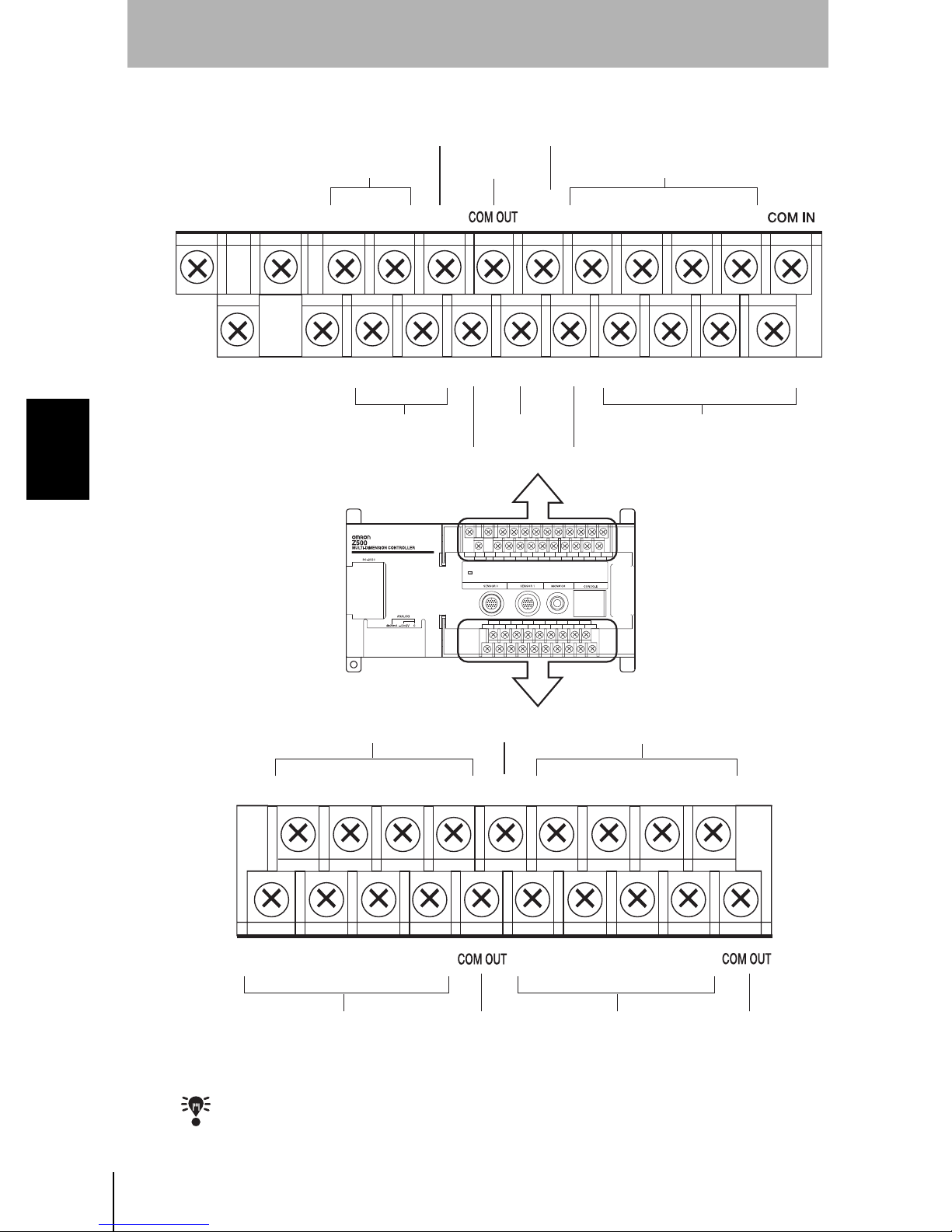
3-1-3 Terminal Names
SECTION 3
3-1 Terminal Block Connections
Control terminal
Measurement result outputs Command inputs
DO 16 DO 18
DO 17
Common
for DO 16 to 19
DO 19
Control terminal
NC
RESET
Reset the Z500
LDOFF
TRIGGER
Control terminalNot connected
DI 1
DI 3
Command inputsMeasurement result outputs
DI 5
DI 6GATE DI 4DI 2DI 0
DI 7
Measurement result outputs
DO 1
DO 0
Measurement result outputs
CHECK
DO 2
Refer to page 152 in the Operation Manual for details on control termin al function.
Z500
42
Setup Manual
DO 3
DO 5
DO 4 DO 6
Not connected
DO 7
for DO 0 to 7
NC
Measurement result outputs
DO 9
DO 8
Measurement result outputsCommon
DO 11
DO 10
DO 12
DO 13
DO 15
DO 14
Common
for DO 8 to 15
Page 45

SECTION 3
Connecting External Devices
NOTICE
CHECK
• Do not rev erse t he connect ions of the signal terminals and COM terminals.
• Using the RESET Signal
Do not input the RESET input immediately after turning ON the power. When using
RESET inp ut to syn chron ize sta rtup tim ing , wait at l east 1 seco nd af ter turn ing ON the
Z500's power supply b efo re tu rni ng O N the R ESET term in al .
The initial s ta t u s of the outp ut terminal s is OFF. The t er m in al s, however, may t ur n O N fo r
approximat ely 0.5 s econd s wh e n t he power is t u r ned ON .
Be sure to allow for this when connecting to an extern al dev ice .
SECTION 3
3-1 Terminal Block Connections
Z500
Setup Manual
43
Page 46
SECTION 3
Connecting External Devices
3-2 RS-232C Connections
The Z500's RS-232C port can be used to connect input signals such as measurement triggers or output
signals such as measurement results. Additionally, data that has been s et in the Z500 can be backed up
in a personal computer.
Refer to the Operation manual for details on communications settings and I/O formats.
SECTION 3
3-2 RS-232C Connections
NOTICE
3-2-1 Connector
In some situations, the RS-232C terminal transmits signals whether the power supply is
ON, OFF, or RESET.
Be sure to allow for this when connecting to an extern al dev ice .
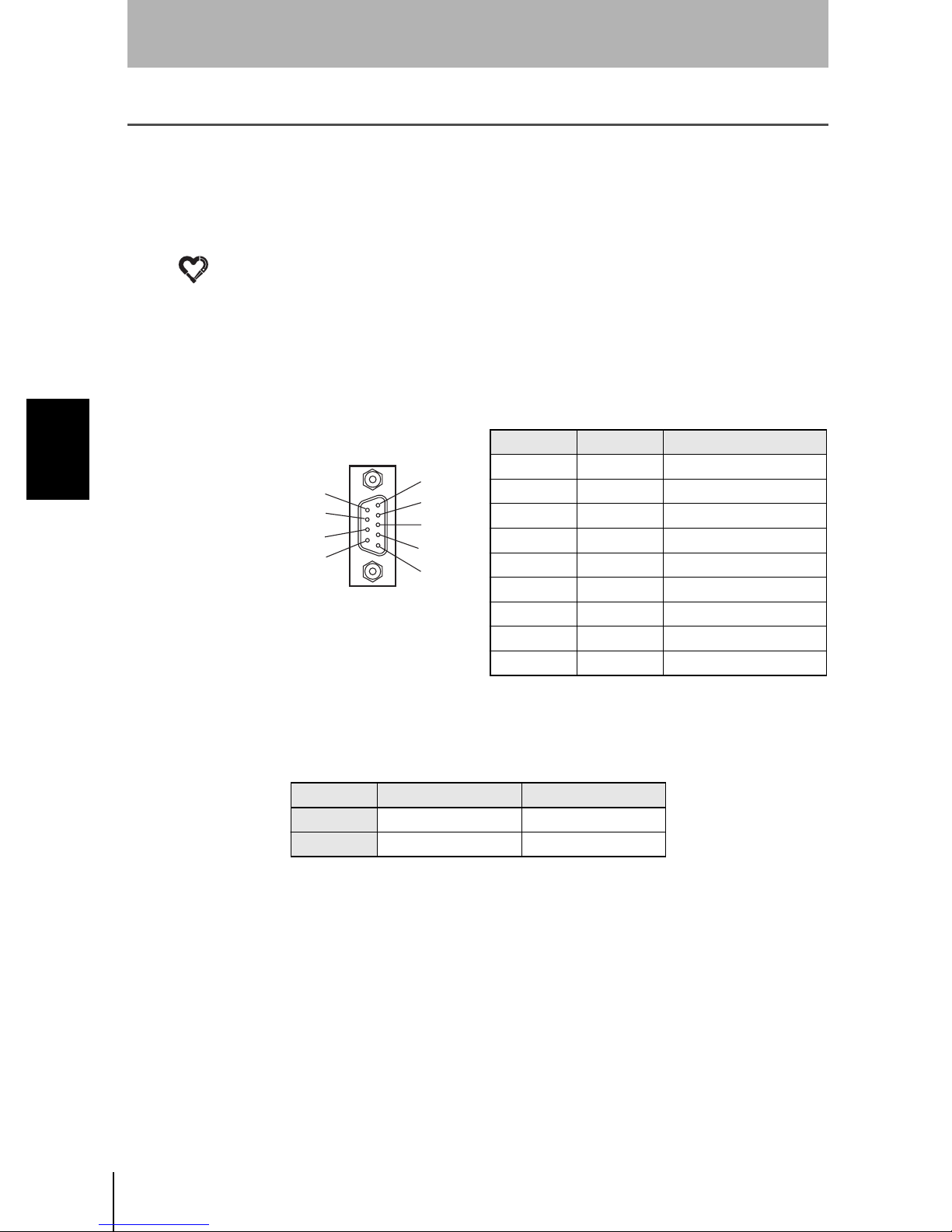
The Z500's RS-232C connector uses 9-pin D-SUB female connectors.
Pin arrangement
Pin No. Signal Function
1 FG (GND) Protective frame ground
5
4
3
2
1
2 SD (TXD) Send D ata
3 RD (RXD) Receive Data
4 RS (RTS) Request to Send
5 CS (CTS) Clear to Send
6 NC Not connected
7 NC Not connected
8 NC Not connected
9 SG (GND) Signal ground
Use a compatible connector.
Recommended Plug and Hood
Type Manufacturer Model
Plug OMRON Corp. XM2A-0901
Hood OMRON Corp. XM2S-0911
Z500
44
Setup Manual
Page 47
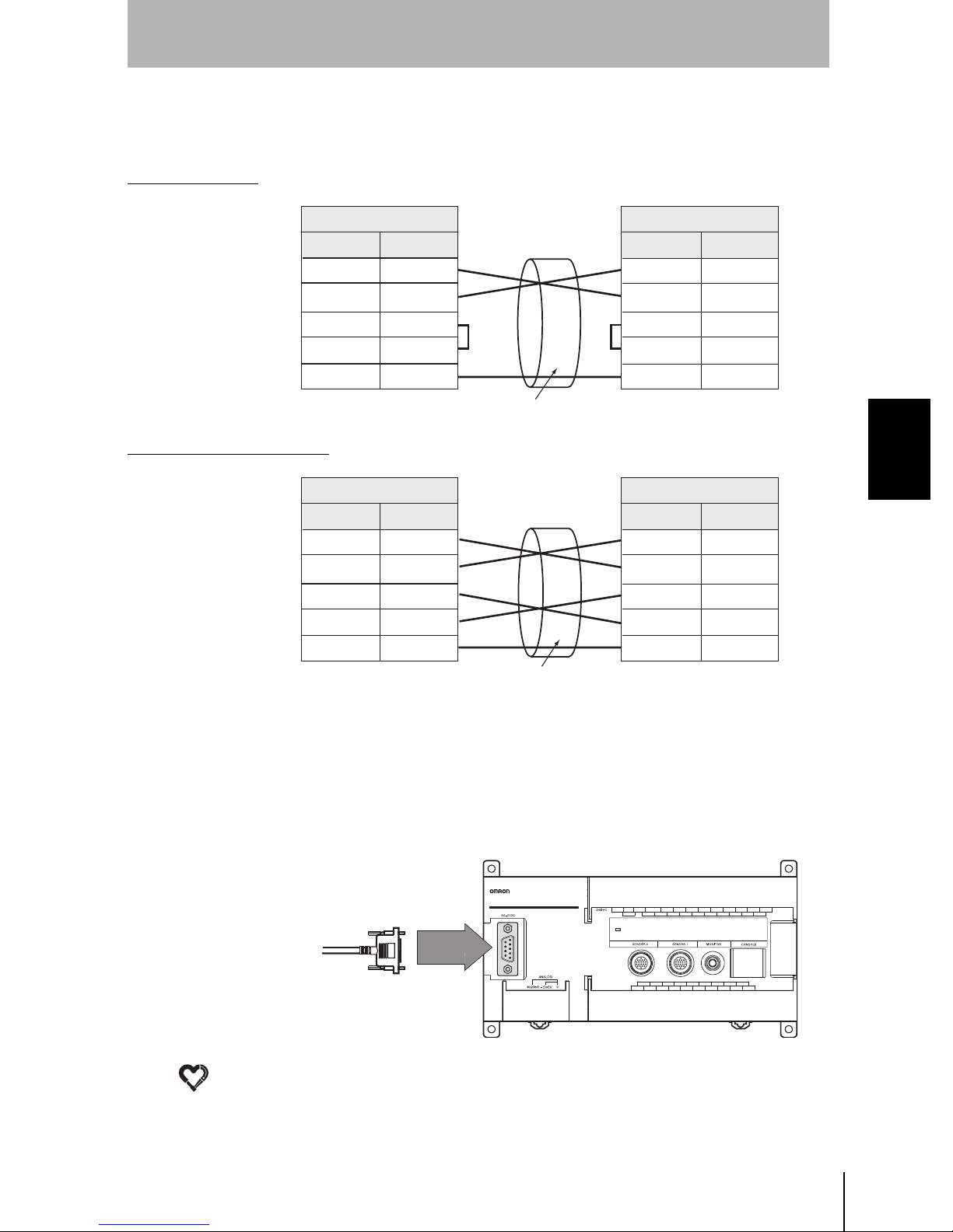
3-2-2 Wiring
Standard Wiring
SECTION 3
Connecting External Devices
The maximum cable length is 15 m.
SD (TXD)
RD (RXD)
RS (RTS)
CS (CTS)
SG (GND)
Wiring for RS/CS Control
SD (TXD)
RD (RXD)
RS (RTS)
CS (CTS)
SG (GND)
Signal
Signal
Z500
Z500
Pin No.
2
3
4
5
9
Pin No.
2
3
4
5
9
Use a shielded cable.
External device
Pin No.
*
*
*
*
*
External device
Pin No.
*
*
*
*
*
Signal
SD (TXD)
RD (RXD)
RS (RTS)
CS (CTS)
SG (GND)
Signal
SD (TXD)
RD (RXD)
RS (RTS)
CS (CTS)
SG (GND)
SECTION 3
3-2 RS-232C Connections
3-2-3 Connection
NOTICE
Use a shielded cable.
* Pin numbers on the external device will depend on the device being connected.
Refer to the manual for the personal computer or PLC being connected.
Align the connector with the socket and press the connect or straight into place.
Tighten the two screws on the edges of the connector.
Z500
MULTI-DIMENSION CONTROLLER
• Always turn OFF the power supply before connecting or disconnecting cables. The
peripheral devic e m ay be da maged if connected or disconnected w ith the pow er supply
turned ON.
• Always tighten the connector screws.
Z500
Setup Manual
45
Page 48

SECTION 3
4
Connecting External Devices
3-3 Linear Sensor Contro l ler Con nections
3-3-1 Cr i mp Te rminals a nd Cables
The terminal block uses M3 terminal screws.
Use appropriate crimp terminals for M3 screws as sho wn b e low.
Tighten the screws to a torque of between 0.5 and 0.6 N·m.
Recommended Crimp Terminals
SECTION 3
3-3 Linear Sensor Controller Connections
Forked
6.0 mm max.
Round
6.0 mm max.
3-3-2 Terminal Names
NOTICE
Re-cover the termin al blocks with the Terminal Block P rotection Covers. Uncovere d
terminal bloc ks can result in electric shock.
Type Manufacturer Model
J.S.T. Mfg Co., Ltd. V1.25-B3A
J.S.T. Mfg Co., Ltd. V1.25-MS3
Recommended
wire size
1.31 to 1.65 mm
2
to20mA -5to5V
Z500
46
Setup Manual
0
Analog output ground connected to input devices.
Analog output terminal for voltage output in the range -5 to 5 V.
Analog output terminal for current output in the range 4 to 20 mA.
Page 49

3-3-3 Internal Specifications
SECTION 3
Connecting External Devices
12V
Internal circuit
12V-12V
Analog output:
4 to 20 mA
Analog output:
-5 to 5V
Analog ground
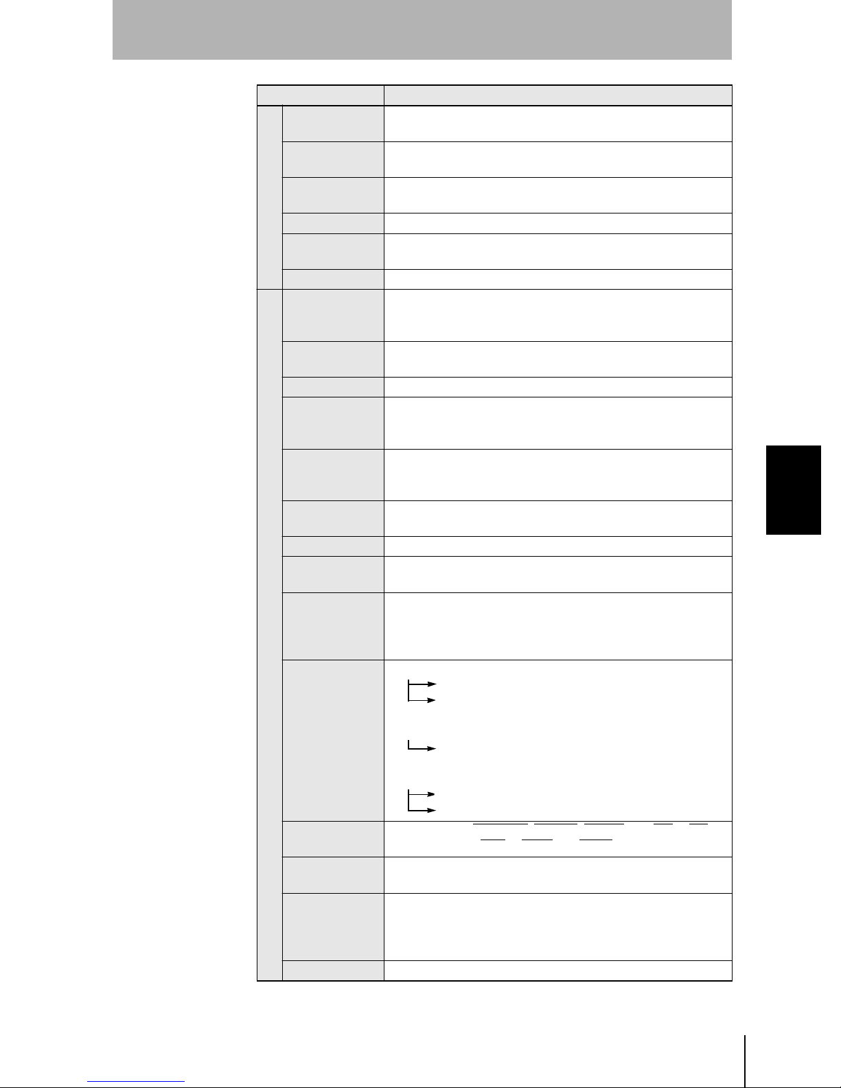
3-3-4 Connection Examples for the Linear Sensor Controller
Connecting to the Linear Sensor Digital Panel Meter (K3TS)
K3TS-SD12B
10 11
1 2 4 5 6 7 8 93
12 13
14
15 16
17
Load
300 max.
SECTION 3
3-3 Linear Sensor Controller Connections
Shield line
24 VDC
4to20mA-5to5V
0
Z500
Setup Manual
47
Page 50

SECTION 3
Connecting External Devices
Connecting to the Linear Sensor Controller (K3AS)
SECTION 3
3-3 Linear Sensor Controller Connections
24 VDC
10
9
8
7
6
5
4
3
2
1
30
29
28
27
25
24
23
22
21
31
K3AS
2032
19
18
17
1626
15
14
13
12
1133
Shield line
Z500
MULTI-DIMENSION CONTROLLER
4to20mA-5to5V
0
Connecting to the Scaling Meter (K3TJ)
1 2 4 5 6 7 8 93
Analog output
Shield line
K3TJ-A116R
24 VDC
Z500
MULTI-DIMENSION CONTROLLER
4to20mA-5to5V
0
Z500
48
Setup Manual
Page 51

Connecting to the Digital Panel Meter (K3NX)
10 11 12 13 14 15 16 17
1 5 6 7 8 93 42
Shield line
24 VDC
Z500
MULTI-DIMENSION CONTROLLER
SECTION 3
Connecting External Devices
K3NX-AD2A
SECTION 3
4to20mA-5to5V
0
Connecting to the Linear Sensor Interface Unit (CQM1-LSE)
Z500
MULTI-DIMENSION CONTROLLER
ZERO
RES
4to20mA-5to5V
0
COM
+24V
DC
1
3
5
7
9
11
13
15
17
CQM1-LSE01
0
2
4
6
8
10
12
14
16
4 to 20 mA
T/O
ZRES
+24V
DC
24 VDC
3-3 Linear Sensor Controller Connections
Z500
Setup Manual
49
Page 52

SECTION 3
SECTION 3
Connecting External Devices
MEMO
3-3 Linear Sensor Controller Connections
Z500
50
Setup Manual
Page 53

Z500
Setup Manual
SECTION 4
Trouble s hooting and Mai ntenance
4-1 Troubleshooting 52
4-2 Maintenance 54
4-3 Specifications and Dimensions 55
SECTION 4 Troublesh ooting and Maintenance
51
Page 54

SECTION 4
Troubleshooting and Maintenance
4-1 Troubleshooting
This section provides information on hardware errors and r emedies to be taken. Refer to this section
before requesting service from your OMRON represent ative.
SECTION 4
4-1 Troubleshooting
HELP
Connection Errors
Problem Probable cause References
The Power indicator is
not lit.
The V i deo Moni t o r is
blank.
The V i deo Moni t o r
image is not clear.
Cannot make key
inputs from the
console.
No images are
displayed.
• The Power Supply is not connected properly.
• The 24-VDC (21. 6 to 26.4-V DC) suppl y volt age
has dropped.
• The po w e r to th e Vid eo M on ito r i s not ON.
• The Mon itor Cabl e is not connecte d properly .
• The Video Moni tor is malfun c t io ning.
• When using a Liquid Crystal Monitor, the power
supply ca pacity i s ins ufficien t.
• There is el ec tric nois e en teri ng from th e po w er
supply or cables.
• The Mon itor Cabl e is not connecte d properly .
• The Cons ole Cable is no t cor rec t l y co nn ec t e d. p.19
• The Sens or cabl e is no t co nn ec t e d to the
Controller correctly.
• There is no workpiece inside the measurement
range.
• The Sensor is not mo unted in the cor r ec t
position.
p.22
p.19
——
p.19
p.28
Z500
52
Setup Manual
Page 55

SECTION 4
Troubleshooting and Maintenance
HELP
HELP
Terminal Block Errors
Problem Probable cause References
Trigger signals
(input signals) are not
received.
Signals cannot be
output externally.
• The cables are not correctly wired.
• The sign al line i s discon ne cted.
• The Z500 is not in Run mode.
• The tri gg er si gn al has not been input.
• The cables are not correctly wired.
• The sign al line i s discon ne cted.
• The Z500 is not in Run mode.
RS-232C Communication Errors
Problem Probable cause References
• The cables are not correctly wired.
No communication s
are possible.
The Unit o perates w ell
initially, but after a
while there is no
response from the
Z500.
• The Z500's communications specifications do
not m atc h thos e of the external d ev ice .
• The Z500 is not in Run mode.
• The reception bu ffer on t he external device
(e.g., personal computer) is full.
Check that settings allow the data to be properly
received.
p.40
p.40
p.44
——
SECTION 4
4-1 Troubleshooting
Z500
Setup Manual
53
Page 56

SECTION 4
Troubleshooting and Maintenance
4-2 Maintenance
In order t o ensu re performanc e, carry out the maintenance procedures given below.
SECTION 4
4-2 Maintenance
NOTICE
• Turn OFF the power and take safety precautions before conducting inspections.
Electric shock can result from attempting safety inspections with the power turned ON.
• Do not use thinners or benzene to clean the Z500.
4-2-1 Cleaning
Optical Filter on Front Panel of Sensor
• Use a blower brush (used to clean camera lenses) to blow large dus t particles
from th e surfac e. Do not blo w the dust a way wit h your mouth.
• Use a soft cloth (for lenses) with a small amount of alcohol to remove the
rema in ing dust.
NOTICE
Do not use a scrubbing action when cleaning as scratches on the filter could result in the
Sensor malfunctioning.
Cleaning of Equipment
Remove dirt on equipment by gent ly wiping with a soft cloth.
4-2-2 Regular Inspections
Inspection point Details
Power su pply
Ambient
temperature
Ambient
humidity
Installation
The vo ltage measured at the power supply termin als
must be 24 VDC + 10 %/ - 10 %.
The operating ambient temperature inside the
cabinet must be between 0 and 50 ºC
The oper a tin g am bient humi dity in si de th e cabine t
must be be tw e en 35% an d 85 %.
Each component must be firmly secured.
Each cabl e co nn ecto r mu st be co rr ectl y in se rte d an d
locked.
Tools
required
Circuit tester
Thermometer
Hygrometer
Phillips
screwdriver
Z500
54
Setup Manual
Page 57

4-3 Specifications and Dimensions
4-3-1 Sensor
Z500-SW2 Sensor
SECTION 4
Troubleshooting and Maintenance
(Unit: mm)
26.4
12
eceiver
Light
Z500-SW17 Sensor
Optical axis
Reference plane
Reception axis
Measurement center
3.5
3
56.5
Monitor
Emitter
Emission axis
Reference plane
Vinyl-insulated round cable 6.8 dia.
Standard length 2m
32
16
(4)
20
4
12
18.1
25
25
65
57
Two, 4.5-dia. holes
4
20
20
Reference plane
65
Operation indicators
4
17 dia.
Connector
(Unit: mm)
20
6.5
SECTION 4
4-3 Specifications and Dimensions
92.1
46
22.7
13 dia.
Emitter
Receiver
18
Optical axis
100
25
4
16.4
16.9
Measurement center
Emission axis
5
2
Reception axis
Reference plane
Vinyl-insulated round cable 6.8 dia.
Standard length 2m
9.5
80
72
70
45.1
36
Three, 4.5-dia. holes
Operation indicators
25
82
100
69
(5)
Connector
8
21 dia.
(15)
9.5
Z500
Setup Manual
55
Page 58
SECTION 4
Troubleshooting and Maintenance
SECTION 4
4-3 Specifications and Dimensions
Model
Run Mode
Distance to
measurement center
Measurement range ±0.8 mm ±16 mm ±20 mm
Light source
Beam dim e nsi ons
(See note 1.)
Linearity
Resolution
Sampling period 9.96 ms
LED indicators
(LASER indicators)
Temper ature character-
istic (See note 9.)
Degree of
protection
Ambient
operating
illumination
Environment
resistance
Materials
Cable le ngth 2 m
Minimum bending
radius
Weight Approx. 350g Approx. 600g
(receiver
side)
Ambient
temperature
Ambient
humidity
Vibration
resistance
(Super High-precision Model)
Mirror reflection Diffuse reflection Mirror reflection Diffuse reflection
20 mm
(with beam cover
attached: 16 mm)
Visible-light semiconductor laser
Refere nc e dis tance : 20 µm × 4 mm TYP.
(Measurement re gion : 2 mm)
±0.1 %F.S.
(See no te 2. )
10 to 150 Hz (double amplitude: 0.35 mm) for 8 min each in X, Y, and Z directions
Z500-SW2
5.2 mm 94 mm 100 mm
Visible-light semiconductor laser
(Waveleng th 65 0 nm ,
1 mW max., Class 2 )
Refere nce dist ance: 60 µm × 45 mm TYP.
(Measurement region: 17 mm)
±0.1 %F.S.
(See note 3.)
0.1 µm
(See no te 5 an d 6.)
Lit while laser is ON.
±0.01 %F.S./ºC
IP64 IP66 (See note 10.)
Illuminatio n at light-receiving surface: 3,000 lx max., incandescent light
Operating: 0 to 50 ºC (with no icing or condensation)
Storage: -15 to 60 ºC (with no icing or condensation)
Operat ing and st orage: 35 % to 85 % (with no condensation)
Controller: Die-cast aluminum
Cable sheathing: Heat-resistant chlorinated vinyl
Connector: zinc alloy and brass
68 mm
Z500-SW17
(Long-range Model)
(Wavelength 658 nm,
15 mW max. , Class 3B )
±0.1 %F.S.
(See note 4.)
1 µm
(See note 7 and 8.)
Z500
56
Setup Manual
Page 59

SECTION 4
Troubleshooting and Maintenance
2
Note 1: Defined at 1/e
present outsid e this range and if the reflection f actor of the light around the
workpiece is high compared to the workpiece, measurement may be affected.
Note 2: Error with respect to the theoretical line representing the displacement output for
measu rement of OMRON standa rd quart z glass. The li nearity v aries wit h the
type of workpiece.
Note 3: Error with respect to the theoretical line representing the displacement output for
measu rement of O MRON stan dard SUS bl ocks. The li nearity va ries with t he
type of workpiece.
Note 4: Error with respect to the theoretical line representing the displacement output for
measu r em e nt of O MRON standard white al u mina cera mics. The linea r i t y varie s
with the type of workpiece.
(13.5%) of the density at the light center. Light may, however, be
Z500-SW17
Note 5: Displacement conve rs io n value fo r pe ak -to-peak of d is placem e nt outp ut. These
figures are for measurement of OMRON standard quartz glass (mirror reflection)
or OMRON standard SUS blocks (diffuse reflection) at the measurement center.
In magnetic fields, it may not be possible to maintain resolution performance
characteristics.
Note 6: These figur es are for w hen the Sensor is connected to the Z500-MC 10, the
average number of measurements is 16.
Note 7: Displacement conversion value for peak-to-peak of displacement output (for
measu rement of OMRON sta ndard white al umina c eramic at the mea surem ent
center). In strong magnetic fields, it may not be possible to maintain resolution
performance characteristics.
Note 8: With t he Z 50 0- M C 1 0, at an ave r ag e nu mb er of m ea su r em e nts o f 64.
Note 9: Value for measurement with the space between the Sensor and the workpiece
(white alum in a ce r a mic) sec ured with an al um inum jig.
Note 10: Enqui re se parat el y ab ou t pr od u cts c onformi ng to IP67.
120mm
Digital output
80mm
80mm
±0.1 % max.
120mm
Distance
SECTION 4
4-3 Specifications and Dimensions
Z500
Setup Manual
57
Page 60

SECTION 4
Troubleshooting and Maintenance
4-3-2 Controller
Z500-MC10 Controller
SECTION 4
4-3 Specifications and Dimensions
87.9
75.5
9 × 7.7=69.3
9 × 7.7=69.3
81.71 23.6
195
83.7
Connector
12.5 dia.
4.1
8
(32.5)
(66.5)
2 × 7.62=15.24
10
98.1 24.5 20
185
3.85
Indicator
148.38
8 × 7.7=61.6
3.85
10
(Unit: mm)
25.1
35.3
8
4
90
100
53.1
36.2
Four, 4.5-dia.
holes
110
50
9 × 7.7=69.3
Item Specification
Supply vo ltag e 21.6 to 26 .4 VD C
Current
consumption
Insulation
resistance
Dielectric
strength
Leakage current 10 mA max.
Noise
resistance
Gener al specifications
Vibration
resistance
Shock
resistance
1A max. (with 2 Sensors connected)
20 MΩ min. between all DC external terminals and GR terminal
(100 VDC Megger, with internal surge absorber removed)
1,000 VAC, 50/60 Hz between all DC external terminals and GR
termi na l (w ith internal surge absorber removed)
1,500 Vp-p; Pulse width: 0.1 µs/1 µs; Risi ng ed ge: 1-n s pu ls e
10 to 1 50 Hz ( double a mplitude: 0.1 mm) for 8 min each in
X, Y, and Z dir ections
2
200m/s
, 3 times each in 6 direc ti ons
44.8
23.3
99.5
Z500
58
Setup Manual
Page 61
SECTION 4
Troubleshooting and Maintenance
Item Specification
Ambient
temperature
Ambient
humidity
Ambient
environment
Ground Ground th e Z 5 00 's gr ound te rm inal to less th a n 100 Ω
Degree of
General specifications
protection
Case material Controller: ABS
Number of
Sensors that
can be mounted
Number of
scenes
Average Average number of times (9 stages, 1 to 256 times)
Light intensity
tracking
function
Measurement
item
Region
specification
Hold functions Sampling, peak, bottom, peak-to-peak, and average
Measurement
data
Equations
Performance specifications
Results output
Terminal block
Monitor
interface
Analog output
resolution
Weight Approx. 70 0g (Co nt roller only )
Note: For measurement at an average number of times of 64 with an OMRON K3AS
Linear Sensor Controller connected.
Operating: 0 to 50 ºC (with no icing or condensation)
Storage: -15 to 60 ºC (with no icing or condensation)
Operating and s torage: 35 % to 85 % (w i t h no conden sation)
No corr o sive ga s e s
IEC60529 IP20 (in-panel)
2
16
Automatic (The li ght intensity tracking range can be specified.)
Fixed ( Sel ect from 3 1 stages .)
Multip le (The light in tensity range c an be s pe c ified.)
Select from the following 8 types:
Height, Step: 2 pts, Step: 3 pts, Edge position, Width,
Edge center, Peak/Bo tto m , Define
Region specification of line beam and displacement direction is
possible.
8 outputs m ax . per sce ne
Equat io ns a re perfor me d w ith r e sp e ct to t he m easu r e me nt
results.
Four-rule equation: +, -, ×, ÷, plus ( )
Functional equation: ABS ( ), MAX ( ), MIN ( ), AVE ( )
• Judgement output A (HIGH, PASS, LOW, ERROR)
RS-232C output
Terminal block output
(Number of simultaneous outputs: 4)
• Judgement output B (OK, NG)
Terminal block output
(Number of simultaneous outputs: 8)
• Measurement value output (measurement value)
RS-232C output
Analog output
11 input points: TRIGGER
21 output poi nts: DO0 to DO19 and GATE
1 channe l ( for pi n jack or ove rsc an mo nit or)
The full scale for output can be divided into a maximum of
40,000 gradations.
Resolution (See note.) 0.25 mV (± 5V)
0.4 µA (4 to 20 µA)
, LD-OFF, RESET, and DI0 to DI7
SECTION 4
4-3 Specifications and Dimensions
Z500
Setup Manual
59
Page 62

SECTION 4
Troubleshooting and Maintenance
4-3-3 Console
Z300-KP Console
(Unit: mm)
SECTION 4
4-3 Specifications and Dimensions
12 dia.
40
34
General specifications
Weight Appro x. 13 5g
4.8 dia.
2000
Item Specification
Vibration
resistance
Shock
resistance
Ambient
temperature
Ambient
humidity
Ambient
environment
Degree of
protection
Minimum
bending radius
Materials
10 to 150 Hz; single-amplitude: 0.15 mm, 4 times for 8 minutes
each in 3 directions
196 m/s
Operating: 0 to +50 ºC (with no icing or condensation)
Storage: -25 to +65 ºC (with no icing or condensation)
Operating and s torage: 35 % to 85 % (w i t h no conden sation)
No corr o sive ga s e s
IEC60529 IP20 (in-panel)
75 mm
Console: ABS
Cable sheathing: Heat-resistant chlorinated vinyl
Connector: PC and PBT
50
23
2
; 3 times each in 6 dire ct ions
510
131.5
87
12.5
Z500
60
Setup Manual
Page 63
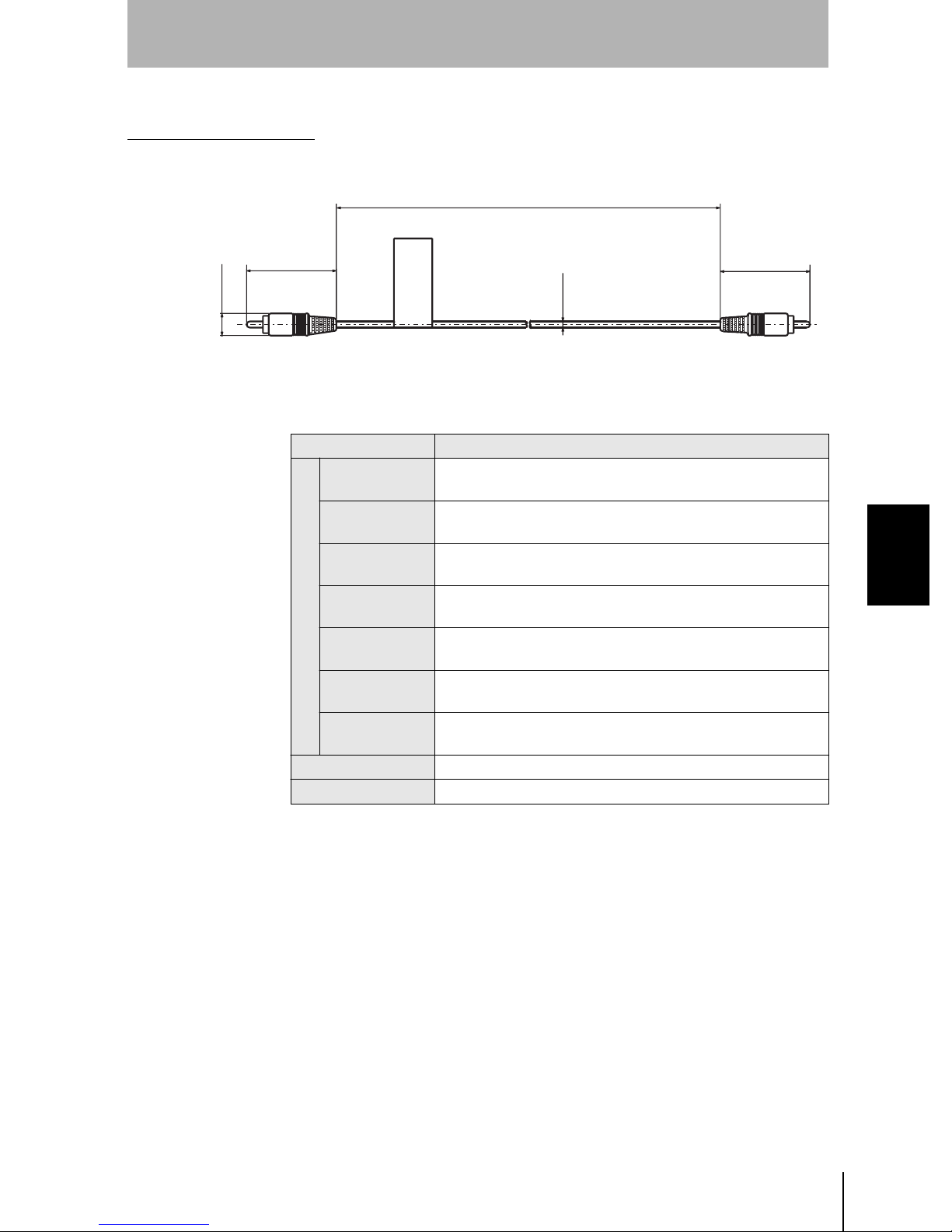
4-3-4 Monitor Cable
F150-VM Monitor Cable
SECTION 4
Troubleshooting and Maintenance
11.5 dia.
46.7
Item Specification
Vibration
resistance
Shock
resistance
Ambient
temperature
Ambient
humidity
Ambient
environment
General specifications
Materials
Minimum
bending radius
Weight Appro x. 40 g
Accessories BNC Jack Adapter
10 to 150 Hz; single-amplitude: 0.15 mm, 4 times for 8 minutes
each in 3 directions
196 m/s
Operating: 0 to +50 ºC (with no icing or condensation)
Storage: -25 to +65 ºC (with no icing or condensation)
Operating and s torage: 35 % to 85 % (w i t h no conden sation)
No corr o sive ga s e s
Cable sheathing: Super he at-resistant chlorinated vinyl
Connector: PVC
50 mm
2
; 3 times each in 6 dire ct ions
2000
(Unit: mm)
46.7
3.3 dia.
SECTION 4
4-3 Specifications and Dimensions
Z500
Setup Manual
61
Page 64

SECTION 4
Troubleshooting and Maintenance
4-3-5 Color Liquid Crystal Monit or
F150-M05L Color Liquid Crystal Monitor
Mounting plate thickness: 1.6 to 4.8
(46 max.)
Mounting brackets
(Unit: mm)
SECTION 4
4-3 Specifications and Dimensions
Panel cutout
dimensions
(100)
143
132
(5.5)
(155)
(145)
50 min.
185
F150-VM Monitor cable
42.2
• Tolerance: ±1mm
174
+0.5mm
133.5
0
+0.5mm
175.5
0
Item Specification
Supply vo ltag e 20 .4 to 26.4 VDC
Curr ent consum ption
Vibration
resistance
Shock resistance 150 m/s
Ambient
temperature
700 mA max.
10 to 150 Hz; single-amplitude: 0.1 mm; maximum accelera-
tion: 15 m/s
2
, 10 times for 8 minutes each in 3 dir e ctions
2
, 3 times each in 6 directions
Operating: 0 to +50 ºC (with no icing or co nd ensati on)
Storage: -25 to +65 ºC (with no icing or co nd ensati on)
Ambient humidity Operating and storage: 35 % to 85 % (with no condensation)
Ambient en vir o nme nt
General specifications
Degree of protection
No corrosive gases
IEC60529 IP20
Materials Case: ABS/PC Display surface: PMMA (Acrylic)
Panel si ze 5.5 inches (111.36 × 83.52 mm (H × V))
Panel type TFT color liquid crystal
Resolution 320 × 240 dots
Image pitch 0.348 (H) × 0.348 (V) mm
Contrast 85:1 (typical)
Viewable angle 25º up/down and 50º left/right (with a contrast ratio > 10)
Luminance 250 cd/m
2
(typical)
Backlight Cold cathode fluorescent light
Resp onse sp eed 60 ms max.
Performance specifications
Input signal NTSC composite video (1.0 V/75 Ω termination)
Weight Approx. 1 kg
Accessories 4 mounting brackets
Z500
62
Setup Manual
Page 65

4-3-6 Video Monitor
F150-M09 Video Monitor
SECTION 4
Troubleshooting and Maintenance
(Unit: mm)
222
2335
143
190
Item Specification
Supply vo ltag e 85 to 264 VAC, 50/60 Hz
Power
consumption
Vibration
resistance
Ambient
temperature
Ambient
humidity
General sp ec ific ati ons
Ambient
environment
Materials
CRT size 9 inch ( 1 64 × 123 mm (H × V))
CRT type Monochrome CRT
Resolution 800 TV lines min. (at center)
System
I/O impedance 75 Ω, high impedance (selectable)
I/O level and
polarity
Performance specifications
Input signal NT SC composit e video (1.0 V/75 Ω termination)
Weight Appro x. 4. 5 kg
20 W max .
5 to 100 Hz; 0.16 -mm dou bl e-ampl itu de or ac celer a t ion of
7.35 m /s
6 times for 10 minutes each in 3 directions
Operating: -10 to +50 ºC (with no icing or condensation)
Storage: -20 to +65 ºC (with no icing or condensation)
Operating and s torage: 10 % to 90 % (w i t h no conden sation)
No corr o sive ga s e s
Front: ABS plastic
Metal pa r t: SE C C (g al vaniz ed s tee l sh ee t )
Number of scanning lines: 600
Horizontal frequency: 15.75 kHz
Field freque ncy: 60 Hz
Composite image signal: 1 V (peak to peak)
Image: 0.7 V (pea k to pe ak ) , pos i ti v e
Synchronization: 0.3 V (peak to peak), negative
2
(whichever is smaller),
50
250
22
160
SECTION 4
4-3 Specifications and Dimensions
Z500
Setup Manual
63
Page 66

Revision History
A manual revision code appears as a suffix to the catalog number on the front cover of the manual.
at. No. Z158-E1-1
Revision code
The f ollowin g tab l e outlin es the changes made to the manual during each revision. Page numbers refer
to the previous version.
Revision code Date Revi sed content
1 Febr uary 20 02 Origin al productio n
Z500
64
Setup Manual
Page 67

OMRON Corporation
Industrial Automation Company
Application Sensors Division
Sensing Devices and Components Division H.Q.
Shiokoji Horikawa, Shimogyo-ku, Kyoto, 600-8530 Japan
Tel:(81)75-344-7068 / Fax:(81)75-344-7107
Regional Headquarters
OMRON EUROPE B.V.
Sensor Business Unit
Carl-Benz Str. 4, D-71154 Nufringen,
Germany
Tel:(49)7032-811-0 / Fax:(49)7032-811-199
OMRON ELECTRONICS LLC
1 East Commerce Drive, Schaumburg, IL 60173
U.S.A.
Tel:(1)847-843-7900 / Fax:(1)847-843-8568
OMRON ASIA PACIFIC PTE.LTD.
83 Clemenceau Avenue, #11-01, UE Square,
239920 Singapore
Tel:(65)835-3011 / Fax:(65)835-2711
OMRON CHINA CO.,LTD.
BEIJING OFFICE
Room 1028, Office Building,
Beijing Capital Times Square,
No.88 West Chang'an Road,
Beijing, 100031 China
Tel:(86)10-8391-3005 / Fax:(86)10-8391-3688
Page 68

Authorized Distributor:
Cat. No. Z158-E1-1 Note: Specifications subject to change without notice. Printed in Japan
0202-
 Loading...