

Page 1
Cat. No. Z159-E1-2 Note: Specifications subject to change without notice. Printed in Japan
0103-0.5C
Authorized Distributor:
Profile Measuring System
Z500
Operation Manual
Profile Measuring System Z500 Manual 2: Operation Manual
Manual
Cat. No. Z159-E1-2
Cat. No. Z159-E1-2
Page 2
About this Manual
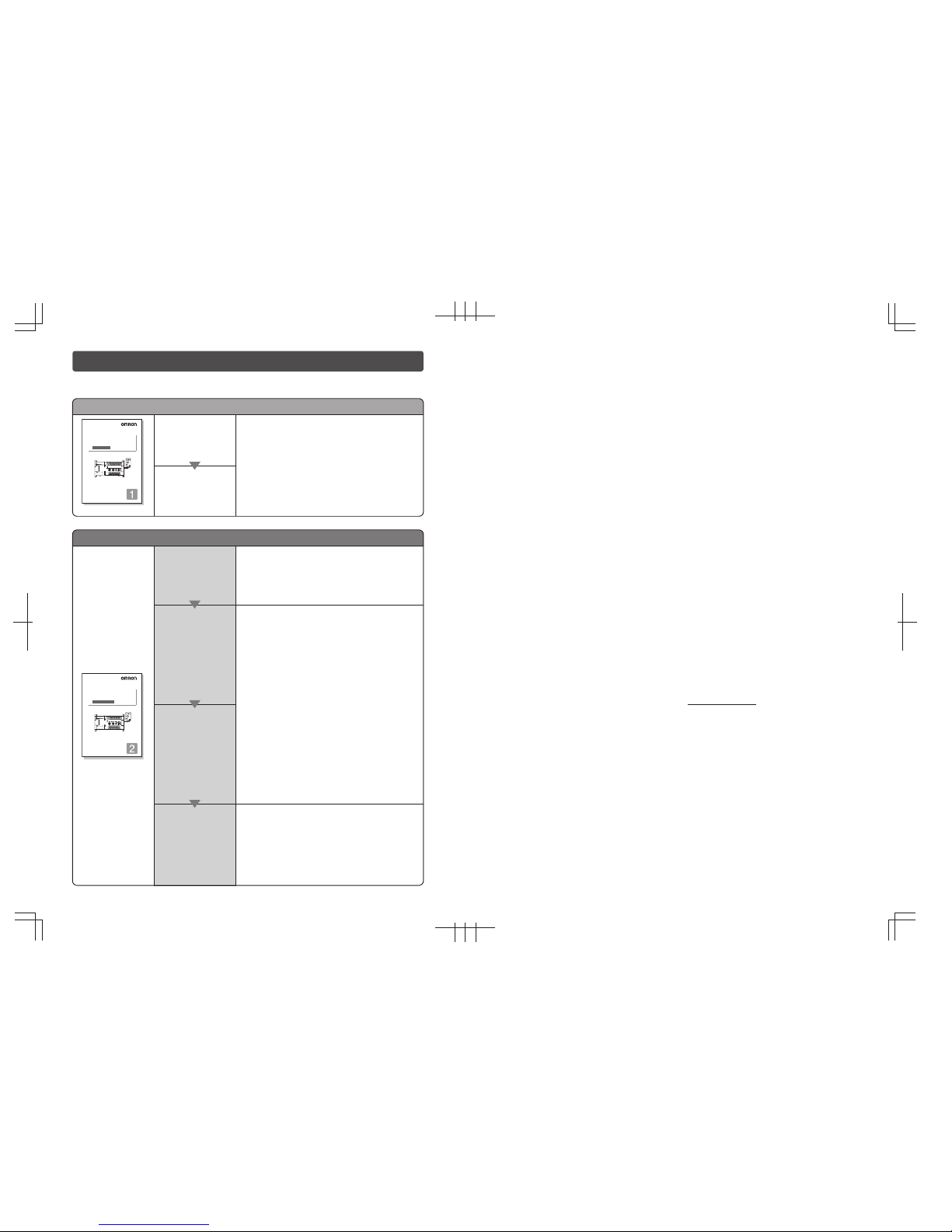
Manual 1: Setup Manual
Installation
Wiring
Please read the following manuals carefully and be sure you understand the information provided
before attempting to install or operate the Z500.
This manual describes the hardware for the Z500
(Multi-Dimensional Controller) and how to install the
components.
Be sure to read this manual first.
Manual 2: Operation Manual
Starting the Z500
and Positioning
the Workpiece
Adjusting Images
Setting
Measurement
Conditions
and Executing
Outputting to
External Devices
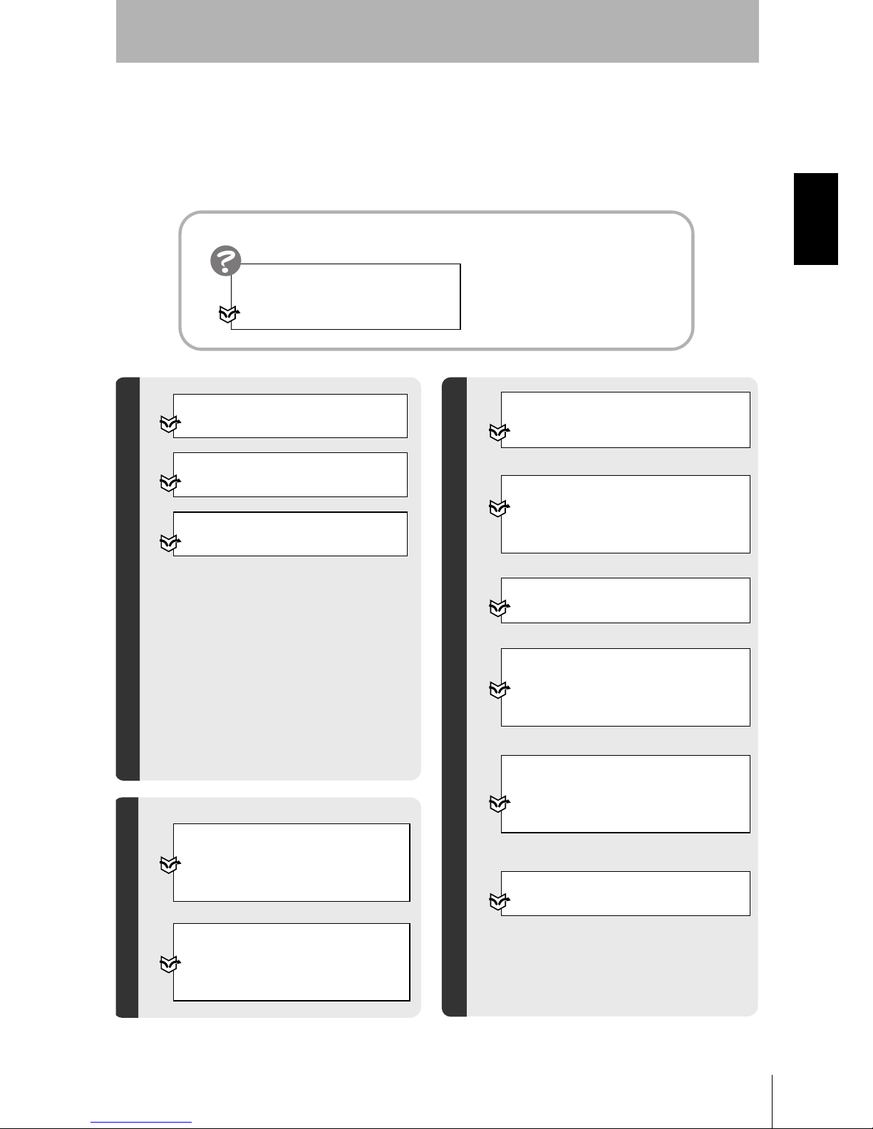
SECTION 2 Basic Operations
This section describes how to start the Z500
and how to display images on the monitor.
SECTION 7 I/O Format
This section provides details on the inputs and outputs
used for communications with external devices via
terminal blocks or RS-232C.
• Communications settings
• I/O format
• Timing for communications
SECTION 3
Menus for Conversational Menu
• Basic settings required for measurement
• Measurement of consistent workpieces
Menus for Conversational Menu
Settings can be made easily by entering
information as requested - just as
though you are having a conversation
with the Z500.
SECTION 4 Menus for Expert Menu
• Customized settings
• Detailed settings
• Measurement of workpieces placed at different
positions
Menus for Expert Menu
More detailed setting, such as position
compensation for workpieces placed at
different positions, can be made.
Cat. No. Z159-E1-2
Multi-Dimensional Controller
Z500
Operation Manual
Manual
Cat. No. Z000-E1-1
Cat. No. Z158-E1-2
Multi-Dimensional Controller
Setup Manual
Manual
Cat. No. Z000-E1-1
Multi-Dimensional Controller
Z500
OMRON Corporation
Industrial Automation Company
Application Sensors Division
Sensing Devices and Components Division H.Q.
Shiokoji Horikawa, Shimogyo-ku, Kyoto, 600-8530 Japan
Tel:(81)75-344-7068 / Fax:(81)75-344-7107
Regional Headquarters
OMRON EUROPE B.V.
Sensor Business Unit
Carl-Benz Str. 4, D-71154 Nufringen,
Germany
Tel:(49)7032-811-0 / Fax:(49)7032-811-199
OMRON ELECTRONICS LLC
1 East Commerce Drive, Schaumburg, IL 60173
U.S.A.
Tel:(1)847-843-7900 / Fax:(1)847-843-8568
OMRON ASIA PACIFIC PTE.LTD.
83 Clemenceau Avenue, #11-01, UE Square,
239920 Singapore
Tel:(65)835-3011 / Fax:(65)835-2711
OMRON CHINA CO.,LTD.
BEIJING OFFICE
Room 1028, Office Building,
Beijing Capital Times Square,
No.88 West Chang'an Road,
Beijing, 100031 China
Tel:(86)10-8391-3005 / Fax:(86)10-8391-3688
Page 3

Manual
1
INTRODUCTION
SECTION 1 SECTION 2 SECTION 3 SECTION 4 SECTION 5 SECTION 6 SECTION 7 SECTION 8
Multi-Dimensional Controller
Z500
Z500-MC10E/MC15E
Operation Manual
INTRODUCTION 2
SECTION 1
Features
9
SECTION 2
Basic Operations
19
SECTION 3
Menus for Conversational Menu
39
SECTION 4
Menus for Expert Menu
53
SECTION 5
Other Functions
109
SECTION 6
System Settings
143
SECTION 7
I/O Format
153
SECTION 8
Troubleshooting
183
Page 4

2
INTRODUCTION
Special or Critical Applications
Z500
Operation Manual
INTRODUCTION
Special or Critical Applications
When the Z500 will be used in one of the conditions or applications listed below, allow extra safety mar-
gins in ratings and functions, add extra safety feature such as fail-safe systems, and consult your
OMRON representative.
• Operating conditions or environments which are not described in the manual
• Nuclear power control systems, railroad systems, aviation systems, vehicles, combustion systems,
medical equipment, amusement equipment, or safety equipment
• Other systems, machines, and equipment that may have a serious influence on lives and property and
require extra safety features
Product Availability
Some of the products listed may not be available in some countries. Please contact your nearest
OMRON sales office by referring to the addresses provided at the back of this manual.
Regulations and Standards
The Z500 complies with the international regulations and standards below:
• EC Regulations
EMC Directive: No.89/336/EEC
• EN Standards (European Standards)
EN61326:1997 + A1:1998 + A2:2001 (EMI:Class A)
© OMRON, 2003
All rights reserved. No part of this publication may be reproduced, stored in a retrieval system, or transmitted, in
any form, or by any means, mechanical, electronic, photocopying, recording, or otherwise, without the prior written
permission of OMRON.
No patent liability is assumed with respect to the use of the information contained herein. Moreover, because
OMRON is constantly striving to improve its high-quality products, the information contained in this manual is subject
to change without notice. Every precaution has been taken in the preparation of this manual. Nevertheless, OMRON
assumes no responsibility for errors or omissions. Neither is any liability assumed for damages resulting from the use
of the information contained in this publication.
Page 5

Z500
Operation Manual
INTRODUCTION
Table of Contents
3
INTRODUCTION
Table of Contents
INTRODUCTION.................................................................................... 3
Table of Contents......................................................................................................... 3
Precaution on Safety ................................................................................................... 5
Menus............................................................................................................................ 6
Editor's Note................................................................................................................. 8
SECTION 1
Features ............................................................................................... 9
1-1 Features of the Z500............................................................................................ 10
1-2 Operational Flow..................................................................................................14
SECTION 2
Basic Operations................................................................................ 19
2-1 Starting the Z500 and Displaying Images..........................................................20
2-2 Menu Operations ................................................................................................ 23
2-2-1 Input Device ............................................................................................... 23
2-2-2 Screen Displays......................................................................................... 24
2-2-3 Menu Tree ..................................................................................................25
2-2-4 Inputting Values ........................................................................................ 27
2-2-5 Adjustment Menu ...................................................................................... 28
2-3 Screen Types and Display Methods .................................................................. 29
2-3-1 Image Monitor............................................................................................ 30
2-3-2 Profile Monitor ........................................................................................... 33
2-3-3 Digital Monitor ........................................................................................... 35
2-3-4 Trend Monitor ............................................................................................ 36
2-4 Saving Settings and Exiting the Z500................................................................37
SECTION 3
Menus for Conversational Menu....................................................... 39
3-1 Setting Measurement Conditions Using the Conversational Menus............... 40
Step
1 Starting Conversational Menus ................................................................ 40
Step
2 Setting Basic Measurement Conditions ..................................................41
Step
3 Setting Measurement Contents ................................................................ 48
Step
4 Setting Measurement Conditions ............................................................. 49
Step
5 Setting Output Contents............................................................................50
Step
6 Starting Measurements .............................................................................51
3-2 Saving Settings and Exiting the Z500................................................................52
Page 6

4
INTRODUCTION
Table of Contents
Z500
Operation Manual
INTRODUCTION
SECTION 4
Menus for Expert Menu...................................................................... 53
4-1 Setting Measurement Conditions Using the Expert Menus.............................54
Step
1 Starting Up Expert Menu and Entering Set Mode .................................. 54
Step
2 Adjusting Images .......................................................................................56
Step
3 Position Compensation ............................................................................. 64
Step
4 Measurement Settings...............................................................................70
Step
5 Measurement Conditions .......................................................................... 88
Step
6 Output Settings ........................................................................................100
Step
7 Performing Measurement........................................................................ 107
4-2 Saving Settings and Exiting the Z500..............................................................108
SECTION 5
Other Functions ............................................................................... 109
5-1 Executing Force-zero ........................................................................................110
5-2 Entering Display Mode ...................................................................................... 112
5-3 Changing the Screen Display ........................................................................... 113
5-4 Changing Scenes .............................................................................................. 125
5-5 Entering Tools Mode ......................................................................................... 128
5-6 Testing Measurement Performance (Test) ...................................................... 129
5-7 Checking the Line Beam Position (Surrounding image) ...............................135
5-8 Backing Up Data to a Computer.......................................................................136
SECTION 6
System Settings ............................................................................... 143
6-1 Entering System Mode ...................................................................................... 144
6-2 Setting RS-232C Communications Specifications (Comm) .......................... 145
6-3 Environment Settings........................................................................................146
6-4 Downloading the Sensor Information to the Controller................................148
6-5 Compensating Installation Error (Slant correct).............................................149
6-6 Initializing the Z500 (Initialize) .......................................................................... 151
6-7 Checking the System Version (Version) ........................................................ 152
SECTION 7
I/O Format ......................................................................................... 153
7-1 Terminal Blocks ................................................................................................. 154
7-2 RS-232C.............................................................................................................. 159
7-3 Analog Output.................................................................................................... 180
SECTION 8
Troubleshooting ............................................................................... 183
8-1 Troubleshooting ................................................................................................184
Index .................................................................................................. 187
Page 7
Z500
Operation Manual
INTRODUCTION
Precaution on Safety
5
INTRODUCTION
Precaution on Safety
OMRON products are manufactured for use according to proper procedures by a qualified operator and
only for the purposes described in this manual.
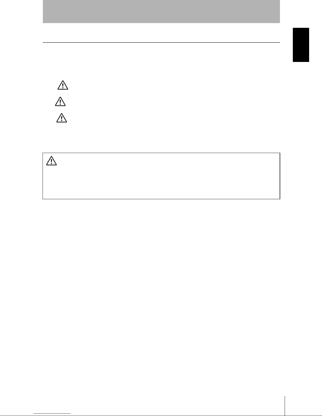
The following conventions are used to indicate and classify precautions in this manual. Always heed the
information provided with them. Failure to heed precautions can result in injury to people or damage to
property.
DANGER
Indicates an imminently hazardous situation which, if not avoided, will result in
death or serious injury.
WARNING
Indicates a potentially hazardous situation which, if not avoided, could result in
death or serious injury.
CAUTION
Indicates a potentially hazardous situation which, if not avoided, may result in
minor or moderate injury, or property damage.
WARNING Failure to read and understand the information provided in this manual may result in
personal injury or death, damage to the product, or product failure. Please read
each section in its entirety and be sure you understand the information provided in
the section and related sections before attempting any of the procedures or opera-
tions given.
Page 8
6
INTRODUCTION
Menus
Z500
Operation Manual
INTRODUCTION
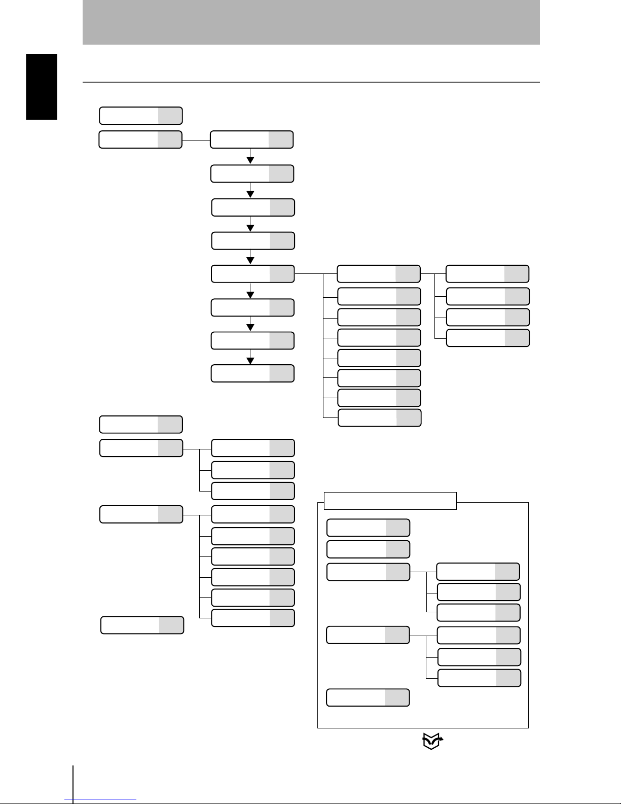
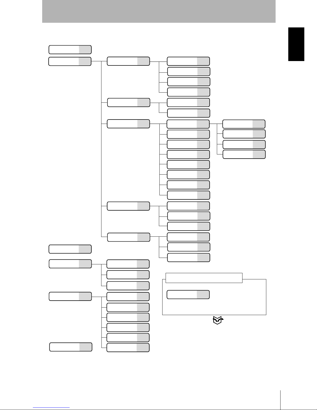
Menus
Menus for Conversational Menu
(OUT0 to OUT7)
P.152
P.37
P.149
P.151
P.145
P.49
P.50
P.52
P.48
P.43
P.41
P.70
P.72
P.70
P.86
P.78
P.84
P.87
P.74
P.70
P.70
P.70
P.76
P.40
P.40
P.51
P.144
P.136
P.135
P.129
P.128
P.44
*1
*1
*1
*1
*1
*1
*1
*
1:The same construction
as that for
Height
RS-232C P.105
P.103
P.100
P.100
P.112
*2
*2:The hierarchy under
Display Mode varies
depending on the type
of screen being displayed.
P.88
P.59
P.63
P.88
P.96
P.90
Scn
(0 to 15)
P.125
Set Start setting
Meas method
Measurement
region
Sensitivity
Meas set
Conditions
Output contents
End setting
Height
Step: 2 pts
Step: 3 pts
Edge position
Width
Edge center
Peak/bottom
Define
Change
Calibrate
Output
Delete
Run
Tools
Test
Surrounding
image
Backup
System
Comm
Slant correct
P.148Download
P.146Environment
Initialize
Version
Sensitivity
Details
Conditions
# to avg
Trigger
Details
Analog
Output
Terminals
Display
Adjustment Menu p.28
Save
When
Define
has been selected, however,
setting of
Calibrate
is disabled.
Item and hierarchy that can be set
through only the adjustment menu
Page 9
Z500
Operation Manual
INTRODUCTION
Menus
7
INTRODUCTION
Menus for Expert Menu
(OUT0 to OUT7)
P.37
P.145
P.100
P.64
P.70
P.56
P.88
P.65
P.69
P.56
P.63
P.70
P.58
P.59
P.88
P.96
P.90
RS-232C
P.100
P.105
P.103
P.70
P.72
P.86
P.78
P.84
P.87
P.74
P.70
P.70
P.70
P.76
(0 to15)
P.125
P.54
P.51
P.144
P.136
P.135
P.129
P.128
*1:The same construction
as that for
Height
P.112
*2:The hierarchy under Display Mode
varies depending on the type of screen
being displayed.
*1
*1
*1
*1
*1
*1
*1
Scn
Set
Image
Meas method
Region
Sensitivity
Details
Compensatn
Reference
Compensation
method
Meas set
Height
Step: 2 pts
Step: 3 pts
Edge position
Width
Edge center
Peak/bottom
Define
Change
Calibrate
Output
Delete
Conditions
Run
Tools
Test
Surrounding
image
Backup
System
# to avg
Trigger
Details
Output
Analog
Terminals
Comm
Save
Display
*2
Adjustment Menu p.28
When
Define
has been
selected, however,
setting of
Calibrate
is
disabled.
Item and hierarchy that can be set
through only the adjustment menu
P.152
P.149
P.151
Slant correct
P.148Download
P.146Environment
Initialize
Version
Page 10

8
INTRODUCTION
Editor’s Note
Z500
Operation Manual
INTRODUCTION
Editor’s Note
Visual Aids
The following headings appear in the left column of the manual to help you
locate different types of information.
NOTICE
Indicates information required to take full advantage of the functions and
performance of the product. Incorrect application methods may result in the loss
of damage or damage to the product. Read and follow all precautionary
information.
CHECK
Indicates points that are important in using product functions or in application
procedures.
REFERENCE
Indicates where to find related information.
TwoSensor
Indicates information required when using 2 sensors.
HELP Indicates information helpful in operation.
Notation
Screen Messages
In this manual, screen message are given in bold/italic.
E.g.: System
System/Backup means the Menu is hierarchical.
OMRON Product References
All OMRON products are capitalized in this manual. The world "Unit" is also
capitalized when it refers to an OMRON product, regardless of whether or not it
appears in the proper name of the product.
Page 11

Z500
Operation Manual
SECTION 1 Features
9
SECTION 1
Features
SECTION 1 explains the features of the Z500 and the flow of operation using the
Conversational and Expert Menus.
1-1 Features of the Z500 10
1-2 Operational Flow 14
Page 12

10
SECTION 1
1-1 Features of the Z500
Z500
Operation Manual
SECTION 1
Features
1-1 Features of the Z500
1-1-1 Eight Measurement Items for Various Detection Needs
Select the measurement item according to application.
Complicated detection is also possible, by combining multiple measurement
items and with detailed settings.
Simultaneous measurement can be performed at 8 points.
REFERENCE
Refer to page 70.
•
Height
•
Step : 2 pts
•
Step : 3 pts
•
Edge position
•
Width
•
Edge center
•
Peak/bottom
•
Define
1-1-2 Simple Setup Using Menus
The Z500 has 2 types of menu. Set the measurement contents according to the
menus displayed on the monitor screen.
Menus for Conversational Menu
Settings can be made easily by entering information as requested - just as
though you are having a conversation with the Z500.
REFERENCE
Refer to page 39.
Menus for Expert Menu
More detailed setting, such as position compensation for workpieces placed at
different positions, can be made.
REFERENCE
Refer to page 53.
1-1-3 A Variety of Output Formats
Not only is analog output available, but data output to external devices can also
be performed via terminal blocks or RS-232C.
REFERENCE
Refer to page 100.
Page 13
Z500
Operation Manual
SECTION 1
1-1 Features of the Z500
11
SECTION 1
Features
1-1-4 Monitoring While Viewing the Measurement Status
The Z500 has 4 types of monitor. Monitoring suited to the application is possible
at every stage from installation and measurement settings to operation and
maintenance.
REFERENCE
Refer to page 29.
PA S S
mm+0005.18800
Zero's OFF
OUT 0
Thru
1div x: 1.000 [s]
y:+10.0000[mm]
9.96ms
S+ / :Display S+ENT:Adjust
Scn 0 Run
PASS
Sen 0
mm
+0005.18800
9.96ms
1div x: 1.000 [s]
y:+10.0000[mm]
Thru
S+ / :Display S+ENT:Adjust
Scn 0 Run
PASSmm
+0005.18800
Zero's OFF
9.96ms
OUT 0
BRIGHT
DARK
FAR
NEAR
[ 15]
[ 170]
[ .]
[ ]
Sen0
LV
PEAK
LV
PEAK
Sen1
S+ / :Display S+ENT:Adjust
Scn 0 Run
Image Monitor
Trend Monitor
Digital Monitor
Profile Monitor
SHIFT
SHIFT
SHIFT
SHIFT
This is the main monitor of the Z500.
Three pieces of information;
measurement status, sensitivity, and
measurement result, can be checked
together with their target images.
Chronological change of height
distribution of 126 points (profile)
can be checked on a shaded 3-D
image.
Chronological change of measured
values can be checked.
Two or more measurement results
can be checked at the same time.
+
+
+
+
SHIFT
SHIFT
SHIFT
SHIFT
++
+
+
9.96ms
0
+0002.65432mm
PASS
HI=+0010.00000
LO=-0010.00000
1
+0004.65432mm
PASS
HI=+0010.00000
LO=-0010.00000
2
+0000.00000mm
ERROR
HI=+0010.00000
LO=-0010.00000
3
-----------mm
HI=+0010.00000
LO=-0010.00000
S+ / :Display S+ENT:Adjust
Scn 0 Run
Page 14
12
SECTION 1
1-1 Features of the Z500
Z500
Operation Manual
SECTION 1
Features
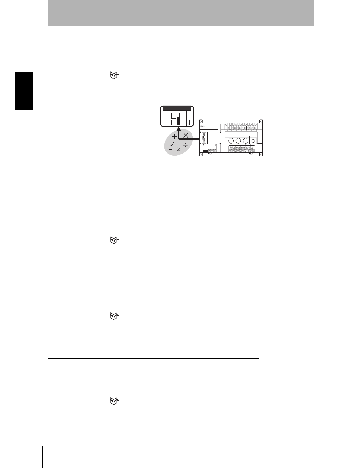
1-1-5 Flexible Settings for Data Output to External Devices
In addition to simply outputting measurement results, equations can be set to
output to external devices using measurement and judgment results.
REFERENCE
Refer to page 70.
1-1-6 A Wide Variety of Useful Functions
Any Type of Workpiece can be Measured by Using the Image Adjustment Function
Higher measurement accuracy can be assured by using the sensitivity
adjustment function, even if the workpieces to be measured have different
brightness.
REFERENCE
Refer to pages 44 and 59.
Adjustment Menu
Six types of adjustments are available on shortcut keys by displaying the
adjustment menu.
REFERENCE
Refer to page 28.
Checking Surrounding Images of the Area that the Line Beam Strikes
Displays images of the area surrounding the part that the line beam strikes.
This function is useful when the Sensor is mounted inside an installation and the
measurement area cannot be checked directly.
REFERENCE
Refer to page 135.
Z500
Page 15

Z500
Operation Manual
SECTION 1
1-1 Features of the Z500
13
SECTION 1
Features
Specifying Measurement Timing by Using the Trigger Function
Measurement timing can be specified arbitrarily by using the self-trigger and
external trigger functions. Characteristic quantity can be held while the
measurement is carried out.
(Measurement status at a set timing can be checked on the monitor screen.)
REFERENCE
Refer to page 90.
Smooth Setup Changes
Scenes can be used to change between up to 16 types of measurement setups.
Simply change the scene to change to a different measurement setup.
REFERENCE
Refer to page 125.
Page 16
14
SECTION 1
1-2 Operational Flow
Z500
Operation Manual
SECTION 1
Features
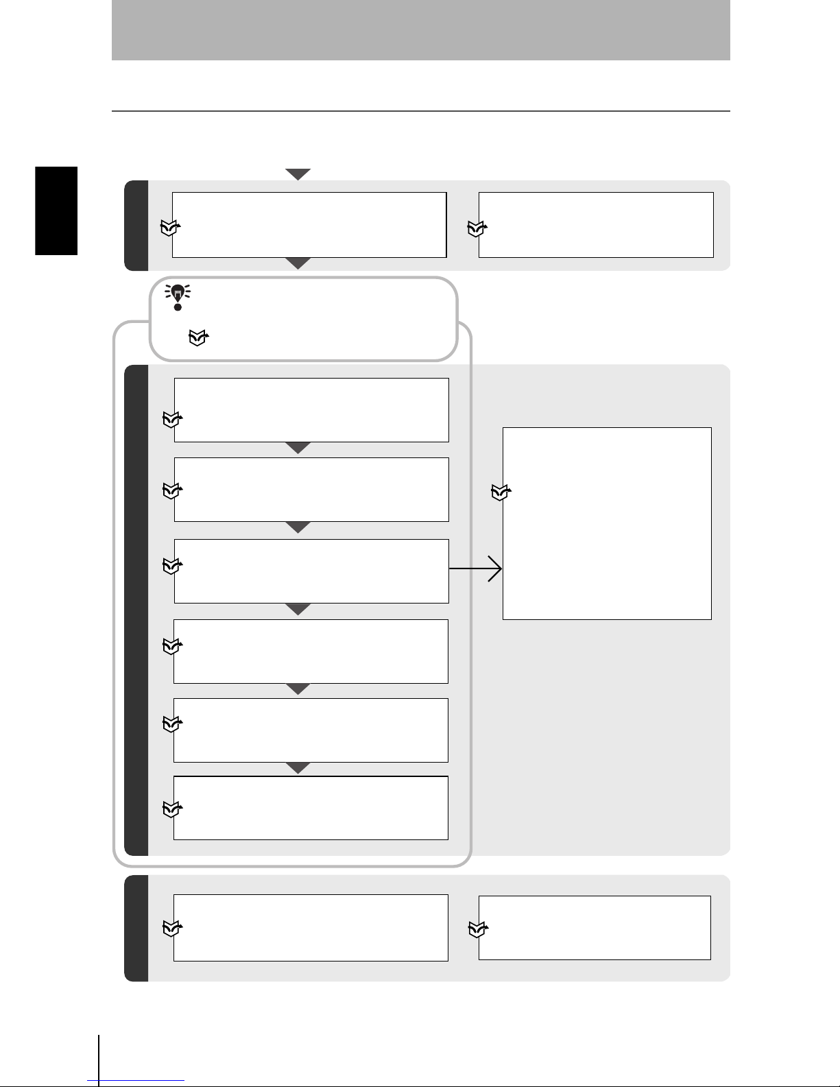
1-2 Operational Flow
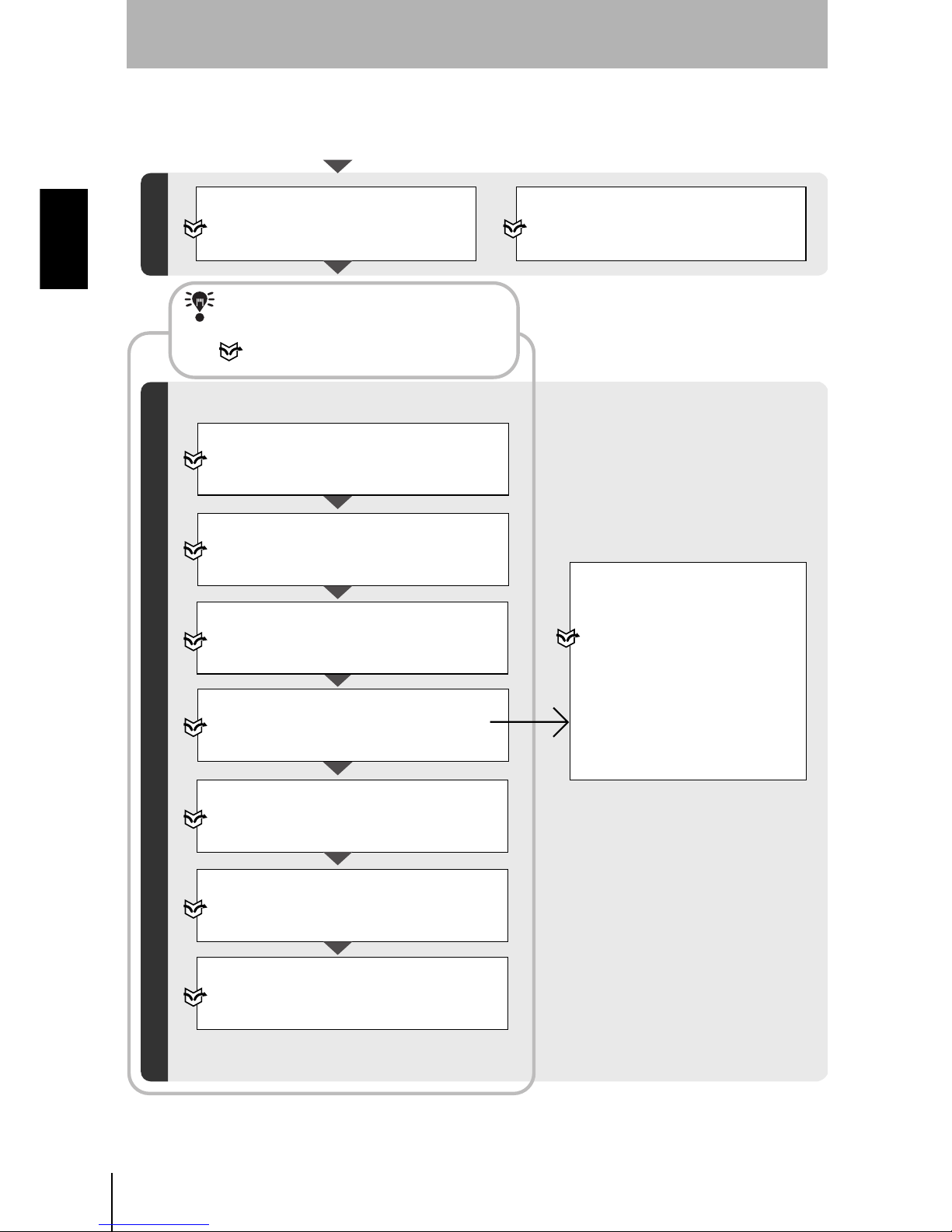
1-2-1 Menus for Conversational Menu
Preparations for Detection
Turn ON the power.
Selecting Measurement Item
Appropriate to the
Measurement Goal
Setting Detection Conditions and Executing
Confirming Settings
Height
Step: 2 pts
Step: 3 pts
Edge position
Width
Edge center
Define
Refer to page 70.
Displaying Images on the Monitor
Refer to page 20,
2-1
Starting the Z500 and Displaying Images.
Screen Types and Display Methods
Refer to page 29.
Starting Up Conversational Menu and
Entering Set Mode
Refer to page 40, See
Step 1 : Starting Conversational Menus.
Setting Basic Measurement Conditions
Refer to page 41, See
Step 2 :
Setting Basic Measurement Conditions.
Setting Measurement Conditions (if necessary)
Refer to page 49, See
Step 4 :
Setting Measurement Conditions.
Refer to page 88 for details.
Selecting and Setting Measurement Items
Refer to page 48, See
Step 3 : Setting Measurement Contents.
Refer to page 70 for details.
Starting Measurements
Refer to page 51, See
Step 6 : Starting Measurements.
Checking the Line Beam Position
Refer to page 135,
5-7Checking the Line
Beam Position (Surrounding image).
Setting Output Contents
Refer to page 50, See
Step 5 : Setting Output Contents.
Refer to page 100 for details.
Performing Test
Refer to page 129,
5-6
Testing Measurement Performance (Test).
Refer to page 39 for information on
settings using Conversational Menu.
Refer to this section to learn about the basic
operational flow from setting measurement
conditions to executing measurements.
CHECK
Page 17
Z500
Operation Manual
SECTION 1
1-2 Operational Flow
15
SECTION 1
Features
Backing up Data
Refer to page 136,
5-8 Backing Up Data
to a Computer (Backup).
Saving Detection Conditions
Refer to page 52,
3-2
Saving Settings and Exiting the Z500.
Initializing the Z500
Refer to page 151.
Setting Conditions by Model Type
Refer to page 125,
5-4
Changing Scenes.
Setting System Environment
Conditions
Refer to page 146,
6-3
Environment Settings.
Communications with External Devices
Refer to page 145,
6-2
Setting RS-232C
Communications Specifications (Comm).
Changing and Deleting Settings
Application Setting Operations
Saving Settings
Executing Force-zero
Refer to page 110.
I/O Format
Refer to page 153.
Clearing Measurement Items
Refer to page 87.
Changing the Screen Display
Refer to page 113.
Changing Measurement Contents
Refer to page 86.
When an error message has
been displayed on the screen,
Refer to page 184,
8-1Troubleshooting.
Troubleshooting
Page 18
16
SECTION 1
1-2 Operational Flow
Z500
Operation Manual
SECTION 1
Features
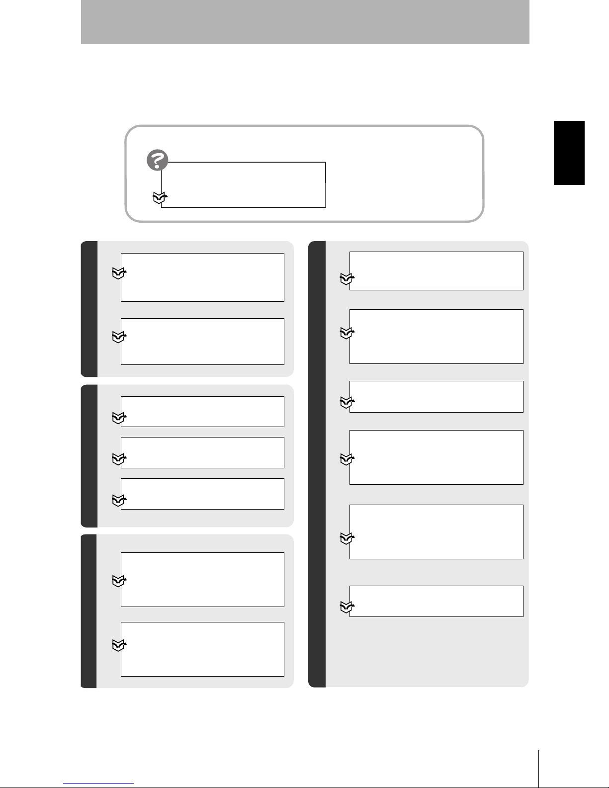
1-2-2 Menus for Expert Menu
Setting Detection Conditions and Executing
Starting Up Expert Menu and Entering Set Mode
Refer to page 54,
Step 1 : Starting Up
Expert Menu and Entering Set Mode.
Adjusting Images
Refer to page 56,
Step 2 : Adjusting Images.
Setting Measurement Conditions
(if necessary)
Refer to page 88,
Step 5 : Measurement Conditions.
Selecting and Setting Measurement Items
Refer to page 70,
Step 4: Measurement Settings.
Starting Measurements
Refer to page 107,
Step 7 : Performing Measurement.
Setting Output Contents
Refer to page 100,
Step 6 : Output Settings.
Setting Position Compensation
(if necessary)
Refer to page 64,
Step 3 : Position Compensation.
Selecting Measurement Item
Appropriate to the
Measurement Goal
Height
Step: 2 pts
Step: 3 pts
Edge position
Width
Edge center
Define
Refer to page 70.
Preparations for Detection
Turn ON the power.
Displaying Images on the Monitor
Refer to page 20,
2-1
Starting the Z500 and Displaying Images.
Screen Types and Display Methods
Refer to page 29.
Refer to page 54 for information on
settings using Expert Menu.
Refer to this section to learn about the basic
operational flow from setting measurement
conditions to executing measurements.
CHECK
Page 19
Z500
Operation Manual
SECTION 1
1-2 Operational Flow
17
SECTION 1
Features
Confirming Settings
Checking the Line Beam Position
Refer to page 135,
5-7
Checking the Line Beam Position
(Surrounding image).
Changing and Deleting Settings
Clearing Measurement Items
Refer to page 87.
Changing the Screen Display
Refer to page 113.
Changing Measurement Contents
Refer to page 86.
Performing Test
Refer to page 129,
5-6
Testing Measurement Performance
(Test).
Backing up Data
Refer to page 136,
5-8
Backing Up Data to a Computer
(Backup).
Saving Detection Conditions
Refer to page 108,
4-2
Saving Settings and Exiting the Z500.
Initializing the Z500
Refer to page 151.
Setting Conditions by Model Type
Refer to page 125,
5-4
Changing Scenes.
Setting System Environment
Conditions
Refer to page 146,
6-3
Environment Settings.
Communications with External Devices
Refer to page 145,
6-2
Setting RS-232C
Communications Specifications (Comm).
Executing Force-zero
Refer to page 110.
I/O Format
Refer to page 153.
Application Setting Operations
Saving Settings
When an error message has been
displayed on the screen,
Refer to page 184,
8-1Troubleshooting.
Troubleshooting
Page 20

18
SECTION 1
1-2 Operational Flow
Z500
Operation Manual
SECTION 1
Features
MEMO
Page 21

Z500
Operation Manual
SECTION 2 Basic Operations
19
SECTION 2
Basic Operations
SECTION 2 shows basic menu operations of the Z500.
2-1 Starting the Z500 and Displaying Images 20
2-2 Menu Operations 23
2-2-1 Input Device 23
2-2-2 Screen Displays 24
2-2-3 Menu Tree 25
2-2-4 Inputting Values 27
2-2-5 Adjustment Menu 28
2-3 Screen Types and Display Methods 29
2-3-1 Image Monitor 30
2-3-2 Profile Monitor 33
2-3-3 Digital Monitor 35
2-3-4 Trend Monitor 36
2-4 Saving Settings and Exiting the Z500 37
Page 22
20
SECTION 2
2-1 Starting the Z500 and Displaying Images
Z500
Operation Manual
SECTION 2
Basic Operations
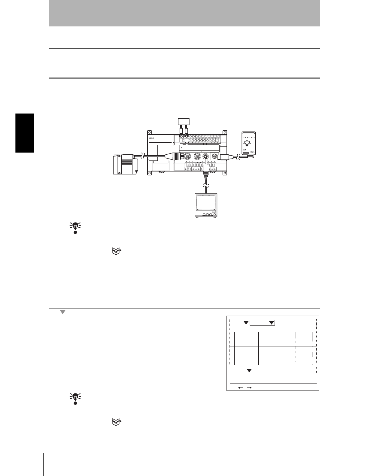
2-1 Starting the Z500 and Displaying Images
This section describes how to start the Z500 and how to display images on the monitor.
Place the workpiece and adjust the Sensor position while monitoring the displayed image.
#1
Starting the Z500
1.
Be sure that the basic Z500 components have been connected correctly.
CHECK
Before connecting components or wiring power supply lines and grounding wires, be sure
to refer to the relevant section in the
Setup Manual
.
REFERENCE
Refer to page 16 in the Setup Manual.
2.
Turn ON the power supply to the monitor.
3.
Turn ON the power supply to the Z500.
The Image Monitor will be displayed.
CHECK
If the Image Monitor is not displayed, use the
SHIFT
+
Right
Keys or
SHIFT
+
Left
Keys
on the console to change the Monitors.
REFERENCE
Refer to page 29, Screen Types and Display Methods.
×× × × × × × × × × × ×
× × ×
×× × × × × ××
× × × × × × × × × ×
× ×
× × × × × × ×
ESC TRIG
SHIFT
ENT
CONSOLE
Z500
Power Supply
Sensor
Monitor
Console
PA S Smm
+0005.18800
Zero's OFF
9.96ms
OUT 0
BRIGHT
DARK
FAR
NEAR
[ 15]
[ 170]
[ .]
[ ]
Sen0
LV
PEAK
LV
PEAK
Sen1
S+ / :Display S+ENT:Adjust
Scn 0 Run
Page 23
Z500
Operation Manual
SECTION 2
2-1 Starting the Z500 and Displaying Images
21
SECTION 2
Basic Operations
#2
Position the Workpiece and Adjust the Image
Position the workpiece to be measured and adjust the displayed image in the
measurement range.
The measurement range varies depending on the Sensor models connected.
REFERENCE
Refer to page 26 in the Setup Manual.
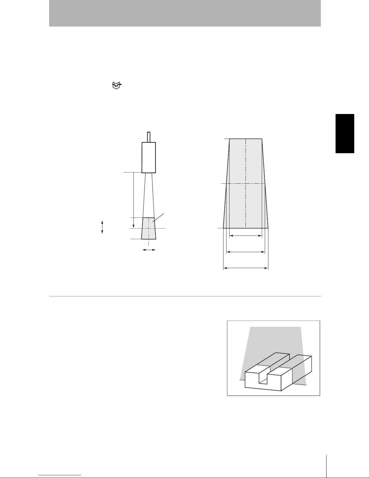
1.
Position the workpiece.
In this example, the workpiece shown in
the right figure will be described.
14.5mm
(±7.25mm)
17.3mm
(±8.65mm)
20.1mm
(±10.05mm)
+20mm
0mm
-20mm
100mm
+20mm
0mm
-20mm
Example: Z500-SW17
Sensor
Measurement range
Height
Position
Page 24
22
SECTION 2
2-1 Starting the Z500 and Displaying Images
Z500
Operation Manual
SECTION 2
Basic Operations
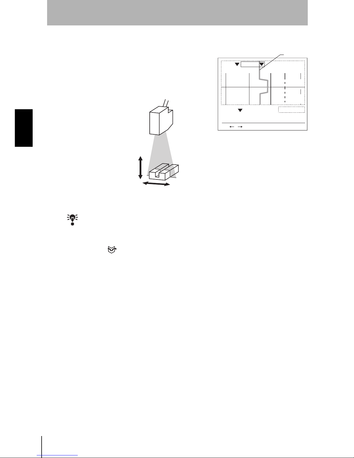
A profile graph showing the level differences in the workpiece will be displayed.
2.
Adjust the position of the workpiece if
necessary.
Adjust the workpiece position if the
Profile graph is not appeared in the
center of the monitor.
CHECK
If the lines representing level differences have swollen elliptically, the light density is
excessive. If the lines are too thin to see, the light density is insufficient. In either case,
adjust the sensitivity.
REFERENCE
Refer to page 59 for information on how to adjust sensitivity.
PA S Smm
+0005.18800
Zero's OFF
9.96ms
OUT 0
BRIGHT
DARK
FAR
NEAR
[ 15]
[ 170]
[ .]
[ ]
Sen0
LV
PEAK
LV
PEAK
Sen1
S+ / :Display S+ENT:Adjust
Scn 0 Run
Profile
Page 25
Z500
Operation Manual
SECTION 2
2-2 Menu Operations
23
SECTION 2
Basic Operations
2-2 Menu Operations
2-2-1 Input Device
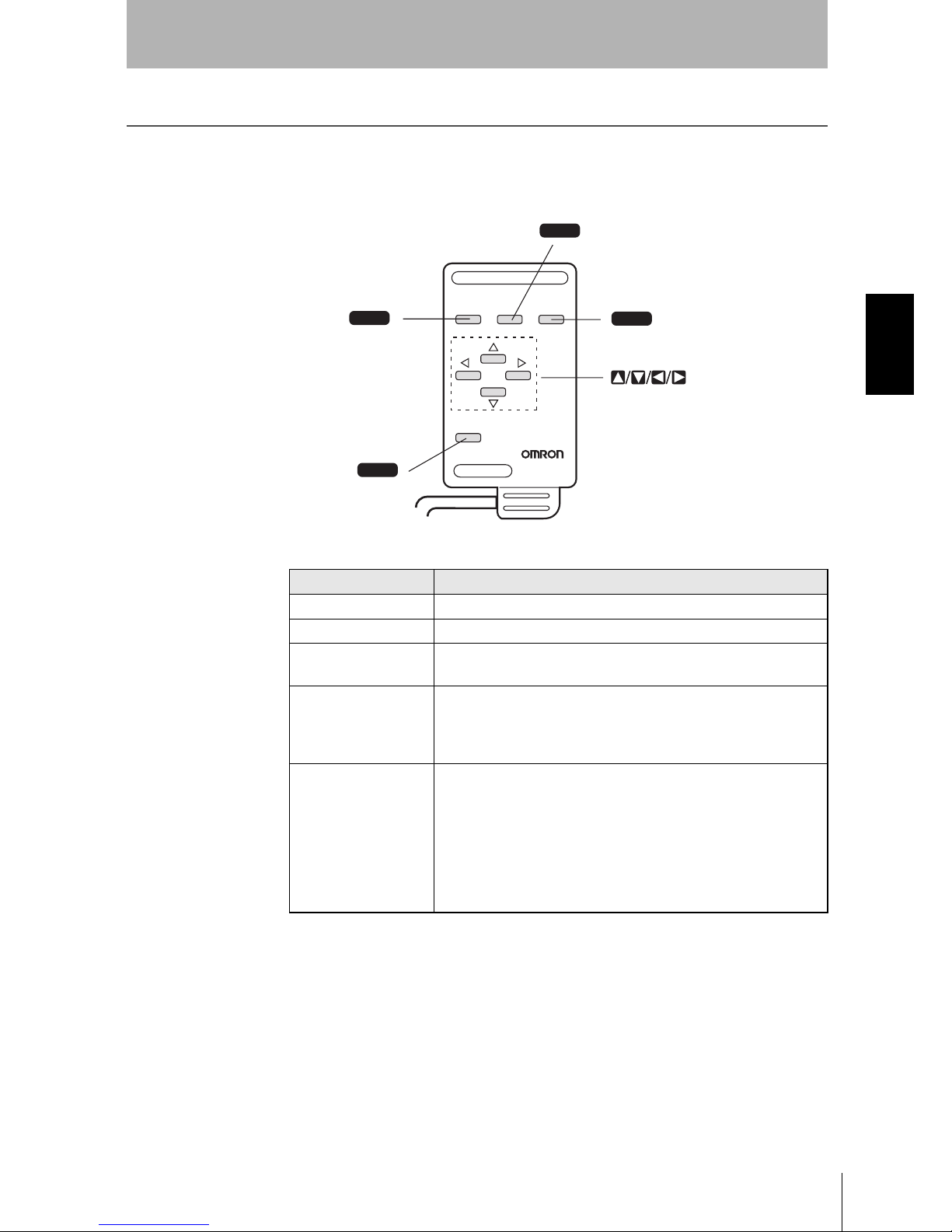
Menu operations are performed on the Console.
Key Function
Escape Key Returns the cursor to the previous menu display or operation.
Trigger Key The effect of the Trigger Key varies with the function.
Enter Key
Executes a function or sets a value.
Note: On the F160-KP, also functions as a Cursor Key.
SHIFT Key
Must be pressed in combination with another key to have any
effect.
Specific functions are assigned to combinations of the
SHIFT
Key and other keys for specific screens.
Up, Down, Left, and
Right Keys
The Up and
Down
Keys are used to move the cursor up and
down and also to set values.
Use the Up Key to increase a value by 1.
Use the
Down
Key to decrease a value by 1.
Hold down the Up or
Down
Key to quickly increase or decrease
a value.
The
Left
and
Right
Keys are used to move the cursor left or
right.
ESC TRIG
SHIFT
Z300-KP
CONSOLE
ENT
ESC
SHIFT
TRIG
ENT
Trigger Key
Enter Key
Up, Down, Left, and Right Keys
Escape Key
SHIFT Key
Page 26
24
SECTION 2
2-2 Menu Operations
Z500
Operation Manual
SECTION 2
Basic Operations
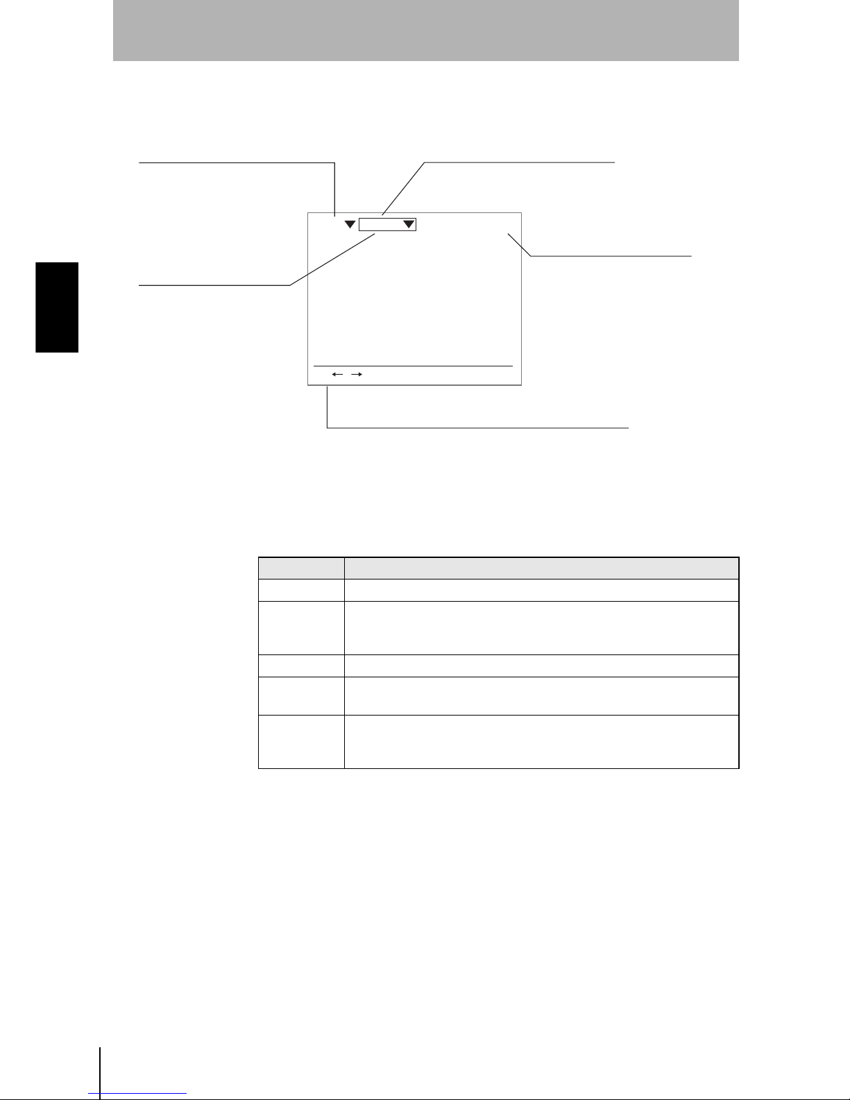
2-2-2 Screen Displays
The Z500 is operated by selecting functions displayed on the screen. Familiarize yourself with each
function before operating the Z500.
Mode
9.96ms
S+ / :Display S+ENT:Adjust
Scn 0 Run
Scene Number
There are 16 scenes.
Setting different measurement
conditions for each one allows
easy switching between different
setups.
Mode (See the table below)
The current operating mode is displayed.
Measurement period (Sampling time)
Key Operations
Displays special key combinations at the bottom of the screen
where available. S refers to the SHIFT Key. "S + ENT" indicates
that the ENT Key should be pressed while the SHIFT Key is pressed.
Cursor Keys
The cursor is moved to the
desired function by pressing
the Up, Down, Left,
and Right Keys.
It varies depending on the item
to be measured.
Display Description
Set Mode to set the inspection conditions.
Run
Performs measurement.
The measurement results are output to an external device via terminal
block or RS-233C.
Tools Used to save settings and images to a computer as backup.
System
Used to set system conditions for the Z500. Select this mode to switch
menus and settings for communications with external devices.
Save
Used to save data to flash memory in the Z500.
If new settings have been made, be sure to save the data before quitting.
Page 27
Z500
Operation Manual
SECTION 2
2-2 Menu Operations
25
SECTION 2
Basic Operations
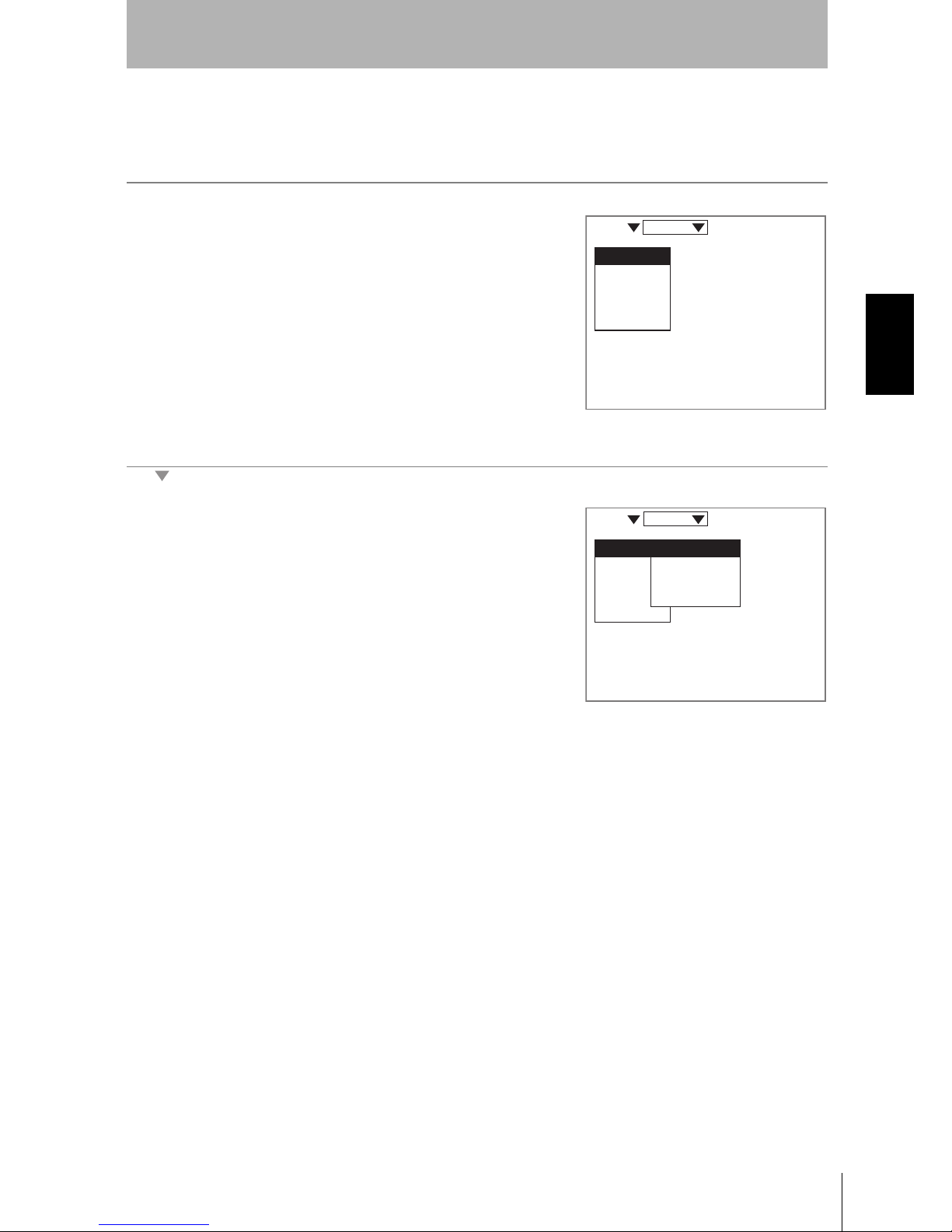
2-2-3 Menu Tree
Z500 menus are hierarchical. The cursor is moved to the required functions to set measurement
conditions. Use the following procedures to move around the menu tree.
1.
Move the cursor to the item to be moved.
(Move the cursor to the desired function
in Set Mode using the Up and Down
Keys.)
2.
Press the ENT Key.
In this example, the cursor will move to the Image Menu.
3.
Repeat (1.) and (2.) to move the cursor
to lower levels.
Press the ESC Key once to move to the
upper level.
Image
Compensatn
Meas set
Conditions
Output
Scn 0 Set
Image
Compensatn
Meas set
Conditions
Output
Meas method
Region
Sensitivity
Details
Scn 0 Set
Page 28
26
SECTION 2
2-2 Menu Operations
Z500
Operation Manual
SECTION 2
Basic Operations
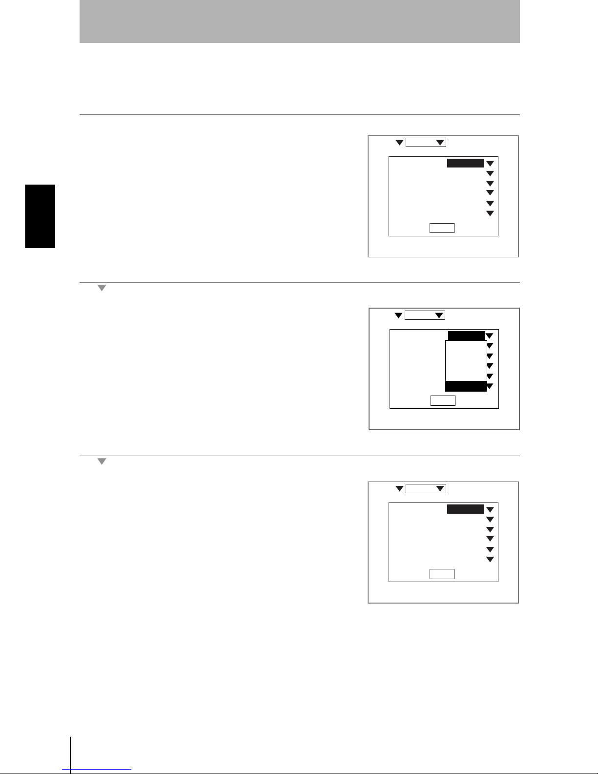
Triangle Mark
Items with an inverted triangle after them have a list of alternatives.The method for selecting the
alternatives is given here.
1.
Move the cursor to the item to be set.
In this example, move the cursor to
Baud rate.
2.
Press the ENT Key.
The selections will be displayed.
3.
Move the cursor to the desired baud rate
using the Up and Down Keys.
4.
Press the ENT Key.
The selections will be registered.
38400bps
8bit
None
1bit
CR
None
End
Scn 0 System
Baud rate
Data Length
Parity
Stop bits
Delimiter
Flow
:
:
:
:
:
:
38400bps
8bit
None
1bit
CR
None
End
2400bps
4800bps
9600bps
19200bps
38400bps
:
:
:
:
:
:
Scn 0 System
Baud rate
Data Length
Parity
Stop bits
Delimiter
Flow
38400bps
8bit
None
1bit
CR
None
End
Scn 0 System
Baud rate
Data Length
Parity
Stop bits
Delimiter
Flow
:
:
:
:
:
:
Page 29
Z500
Operation Manual
SECTION 2
2-2 Menu Operations
27
SECTION 2
Basic Operations
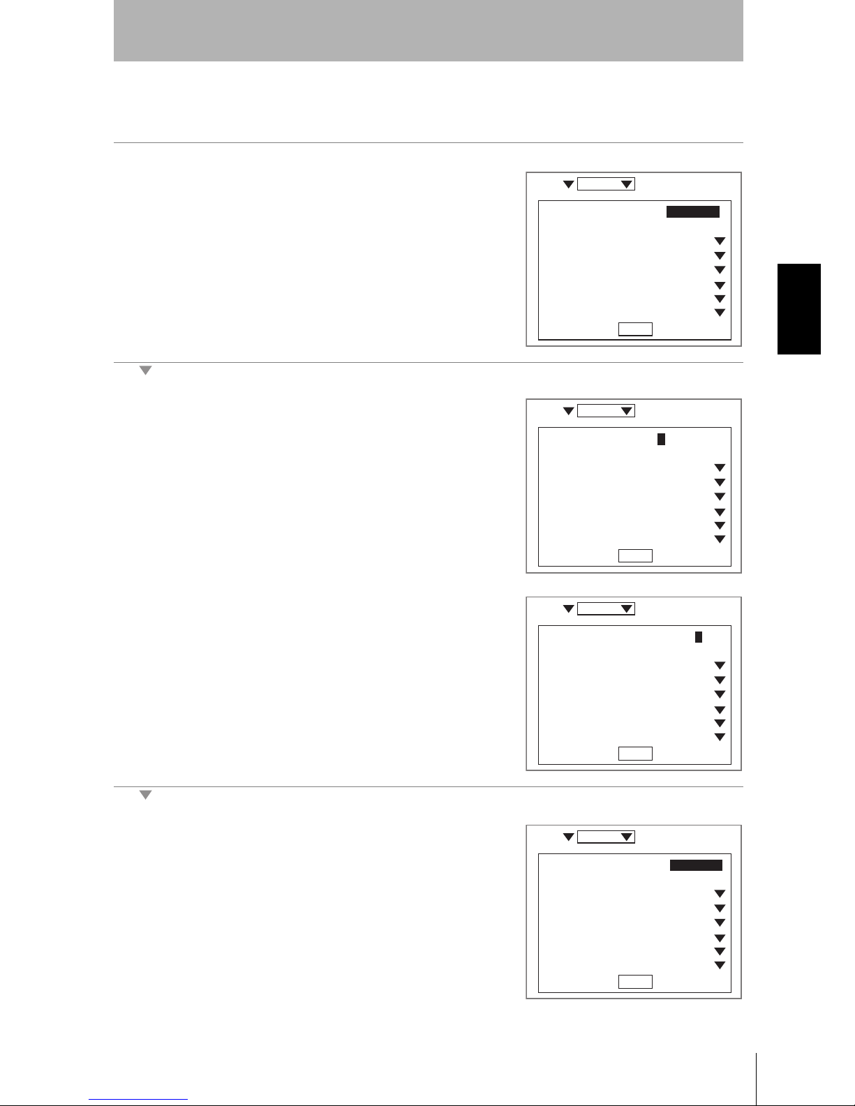
2-2-4 Inputting Values
The section explains how to input values when setting judgment or measurement conditions.
1.
Move the cursor to the item for which a
value is to be changed.
2.
Press the ENT Key.
The cursor will change to a cursor the size of a single digit.
3.
Move the cursor to the digit to be
changed using the Left and Right Keys.
4.
Change the value.
Use the Up Key to increase the value.
Use the Down Key to decrease the
value.
5.
Repeat (4.) to change other values.
6.
Press the ENT Key.
The values will be set.
End
:
:
:
:
:
:
:
:
Scn 0 Set
[ 0.01000]
[ 0.00000]
None
2pixel
50.0%
Clamp
None
5pixel
judgement width
Edge width
Smoothing
Noise
Level
Error data
Profile
Peak/btm width
End
:
:
:
:
:
:
:
:
Scn 0 Set
None
2pixel
50.0%
Clamp
None
5pixel
judgement width
Edge width
Smoothing
Noise
Level
Error data
Profile
Peak/btm width
[0000.01000]
[ 0.00000]
End
:
:
:
:
:
:
:
:
Scn 0 Set
None
2pixel
50.0%
Clamp
None
5pixel
judgement width
Edge width
Smoothing
Noise
Level
Error data
Profile
Peak/btm width
[0000.02000]
[ 0.00000]
End
:
:
:
:
:
:
:
:
Scn 0 Set
None
2pixel
50.0%
Clamp
None
5pixel
judgement width
Edge width
Smoothing
Noise
Level
Error data
Profile
Peak/btm width
[ 0.02000]
[ 0.00000]
Page 30
28
SECTION 2
2-2 Menu Operations
Z500
Operation Manual
SECTION 2
Basic Operations
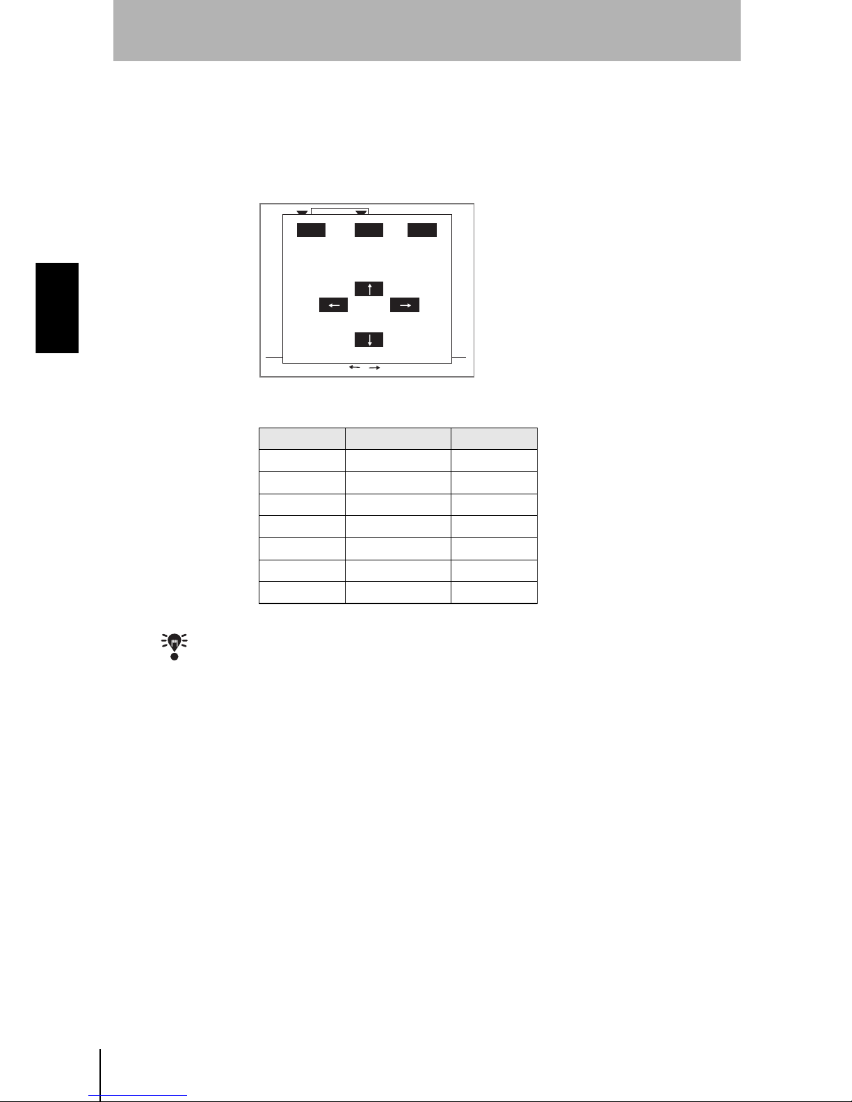
2-2-5 Adjustment Menu
Press the SHIFT + ENT Keys in Run Mode. The adjustment menu will be displayed.
The adjustment menu is useful to display the set screens of the following six items without passing
through the menu hierarchies.
CHECK
The adjustment menu can be performed from the Image Monitor, the Digital Monitor, the
Profile Monitor, or the Trend Monitor.
Key Allocation Reference
Trigger Key Display P.112
Enter Key Test P.129
Up Key Sensitivity P.59
Down Key Conditions P.88
Left Key Output P.100
Right Key Meas set P.70
Escape Key None -
Scn 0 Run
9.96ms
ESC:Back S+ / :Switch display
ESC TRG ENT
Display
Test
Sensitvy
Output
Meas set
Conditns
Page 31

Z500
Operation Manual
SECTION 2
2-3 Screen Types and Display Methods
29
SECTION 2
Basic Operations
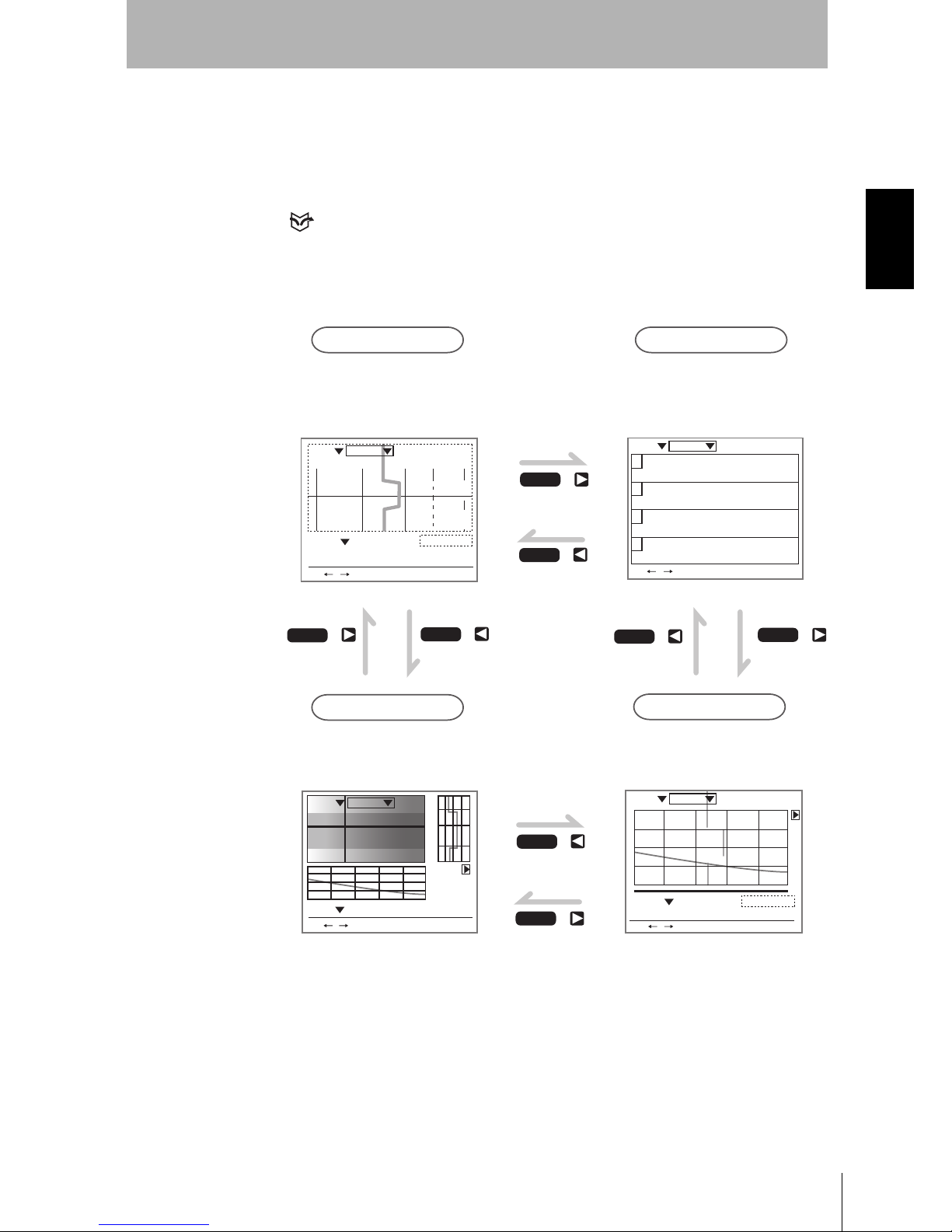
2-3 Screen Types and Display Methods
There are 4 Monitors to display images on the Z500; Image Monitor, Digital Monitor, Trend Monitor, and
Profile Monitor. These monitors are useful to check measurement information as required from various
viewpoints. Use the SHIFT + Right Keys or SHIFT + Left Keys on the console to change the Monitors.
The first time the power supply is turned ON after delivery, the Image Monitor is displayed.
CHECK
Enable to select which Monitor will be displayed when the Z500 turns ON.
REFERENCE
Refer to page 146.
CHECK
Measurement continues even while the screen is switched.
PA S S
mm+0005.18800
Zero's OFF
OUT 0
Thru
1div x: 1.000 [s]
y:+10.0000[mm]
9.96ms
S+ / :Display S+ENT:Adjust
Scn 0 Run
PASS
Sen 0
mm
+0005.18800
9.96ms
1div x: 1.000 [s]
y:+10.0000[mm]
Thru
S+ / :Display S+ENT:Adjust
Scn 0 Run
PASSmm
+0005.18800
Zero's OFF
9.96ms
OUT 0
BRIGHT
DARK
FAR
NEAR
[ 15]
[ 170]
[ .]
[ ]
Sen0
LV
PEAK
LV
PEAK
Sen1
S+ / :Display S+ENT:Adjust
Scn 0 Run
Image Monitor
Trend Monitor
Digital Monitor
Profile Monitor
SHIFT
SHIFT
SHIFT
SHIFT
This is the main monitor of the Z500.
Three pieces of information;
measurement status, sensitivity, and
measurement result, can be checked
together with their target images.
Chronological change of height
distribution of 126 points (profile)
can be checked on a shaded 3-D
image.
Chronological change of measured
values can be checked.
Two or more measurement results
can be checked at the same time.
+
+
+
+
SHIFT
SHIFT
SHIFT
SHIFT
++
+
+
9.96ms
0
+0002.65432mm
PASS
HI=+0010.00000
LO=-0010.00000
1
+0004.65432mm
PASS
HI=+0010.00000
LO=-0010.00000
2
+0000.00000mm
ERROR
HI=+0010.00000
LO=-0010.00000
3
-----------mm
HI=+0010.00000
LO=-0010.00000
S+ / :Display S+ENT:Adjust
Scn 0 Run
Page 32

30
SECTION 2
2-3 Screen Types and Display Methods
Z500
Operation Manual
SECTION 2
Basic Operations
2-3-1 Image Monitor
This is the main monitor of the Z500. The first time the power supply is turned ON after delivery, this
screen is displayed. Mostly used to check the measurement status, sensitivity information, and
measurement results.
Image Monitor consists of 2 displays; Measurement status display and Measurement sensitivity display.
Use the TRIG Key to change the displays.
Measurement Status Display
The height information within the measurement range can be checked.
The height information between 0 and 125 lines is displayed with the Profile
graph.
PA S Smm
+0005.18800
OUT 0
BRIGHT
DARK
FAR
NEAR
[ 15]
[ 170]
[ .]
[ ]
9.96ms
Zero's OFF
Sen0
LV
PEAK
LV
PEAK
Sen1
S+ / :Display S+ENT:Adjust
Scn 0 Run
PA S Smm
+0005.18800
Zero's OFF
9.96ms
OUT 0
BRIGHT
DARK
FAR
NEAR
[ 15]
[ 170]
[ .]
[ ]
Sen0
LV
PEAK
LV
PEAK
Sen1
S+ / :Display S+ENT:Adjust
Scn 0 Run
TRIG
Measurement Status Display
Screen Displays
Measurement
Result Display
(See note)
Measurement Sensitivity Display
Note:
Common to Measurement status display and Measurement sensitivity display.
PA S Smm
+0005.18800
Zero's OFF
9.96ms
OUT 0
FARNEAR
[ 15]
[ 170]
[ .]
[ ]
Sen0
LV
PEAK
LV
PEAK
Sen1
S+ / :Display S+ENT:Adjust
Scn 0 Run
BRIGHT
DARK
Sensor
Line beam
Workpiece
Measurement range
Measurement center
LowHigh
Line 0
Line 125
Measurement region (green)
Profile (yellow)
Height
Position
Page 33

Z500
Operation Manual
SECTION 2
2-3 Screen Types and Display Methods
31
SECTION 2
Basic Operations
CHECK
The Profile graph can be enlarged.
REFERENCE
Refer to page 113.
CHECK
The Profile graph can be output as a measurement value to an external device.
REFERENCE
Refer to page 101.
CHECK
Whether or not the lines interfering with the measurement should be interpolated can be
determined.
REFERENCE
Refer to page 99.
CHECK
The measurement region can be changed.
REFERENCE
Refer to page 58.
Measurement Sensitivity Display
The Measurement sensitivity level (LV) and received level (PEAK) can be
checked. The light density and the status of the workpiece surface at a cursor
position are displayed with the line brightness graph.
CHECK
The line brightness graph for the specified range can be enlarged.
REFERENCE
Refer to page 113.
PASSmm
+0005.18800
OUT 0
BRIGHT
DARK
FARNEAR
[ 15]
[ 170]
[ .]
[ ]
9.96ms
Zero's OFF
Sen0
LV
PEAK
LV
PEAK
Sen1
S+ / :Display S+ENT:Adjust
Scn 0 Run
LV [ 15]
PEAK[170]
Cursor (Red)
Refer to page 116 for information on how to
change cursor position.
Measurement period (Sampling time)
Line beam image
The shape of workpieces and
the way they are detected
can be checked.
LV: Displays current sensitivity level. (1 to 31)
The value increases with increase in darkness of the
workpiece, while it decreases with increase in
brightness of the workpiece.
PEAK: Displays current received level.
Use this value as reference when setting
the sensitivity level.
120 max.: Insufficient light density
255 min.: Excessive light density
For details on sensitivity adjustment method,
refer to page 59.
Line Brightness (Brightness Distribution)
The line brightness graph at the cursor position is displayed.
It is possible to know at a glance whether or not, for example,
the light density is insufficient, or is at the saturation level.
Bright
Brightness
Dark
High
Low
Height
Page 34

32
SECTION 2
2-3 Screen Types and Display Methods
Z500
Operation Manual
SECTION 2
Basic Operations
Measurement Result Display
Check whether the measurements are correctly performed.
The measurement points and the measurement values are displayed.
CHECK
Offset can be set for Force-zero.
REFERENCE
Refer to page 84.
PASSmm
+0005.18800
9.96ms
OUT 0
FARNEAR
[ 15]
[ 170]
[ .]
[ ]
BRIGHT
DARK
Zero's OFF
Sen0
LV
PEAK
LV
PEAK
Sen1
S+ / :Display S+ENT:Adjust
Scn 0 Run
Measurement points (red)
Forced-zero
Zero's OFF: Forced-zero not executed
Zero's ON: Forced-zero executed
Judgment results
Measurement value
The measurement value is displayed
in green if the judgment result is PASS.
It is displayed in red if the judgment
result is HIGH, LOW, or ERROR.
Output number
The output number for the currently displayed
measurement result is displayed.
The measured points are displayed.
No point is displayed when the measurement is in error.
The level and range necessary for the determination of
measurement points are represented by thin lines.
(In this example, the distance between the 2 points is
measured.)
HIGH : Greater than the judgment upper limit
PASS : Within the judgment limits
LOW : Less than the judgment lower limit
ERROR : Measurement error
-The workpiece is out of the measurement range
-The light density is insufficient
-Information on the measurement point
cannot be obtained, or other cases
RESET: No-measurement state
LD-OFF: LD-OFF input
Page 35

Z500
Operation Manual
SECTION 2
2-3 Screen Types and Display Methods
33
SECTION 2
Basic Operations
2-3-2 Profile Monitor
Use to check the status of the workpiece surface.
Surface condition of a workpiece can be monitored on a shaded 3-D image screen. Height information
and its chronological change can also be monitored.
By moving the workpiece, the profile graph (height information for 126 points) can be monitored in
chronological order for up to 10 seconds.
TRIG Key can be used for switching from waveform display to waveform display stop and vise versa.
The trigger function enables shaded 3-D image to be displayed at specified timing.
CHECK
Display range and display time can be changed.
REFERENCE
Refer to page 121.
PA S S
Sen 0
mm
+0005.18800
9.96ms
1div x: 1.000 [s]
y:+10.0000[mm]
Thru
S+ / :Display S+ENT:Adjust
Scn 0 Run
Trend Display
Profile Display
Measurement Result Display
Shaded 3-D image display
Line beam
Movement orientation
Page 36

34
SECTION 2
2-3 Screen Types and Display Methods
Z500
Operation Manual
SECTION 2
Basic Operations
Shaded 3-D Image Display and Profile Display
Surface condition of a workpiece is displayed by a shaded 3-D image with 0 to
255 gradations. A low section is displayed darkly, while a higher section is
displayed brightly.
Trend Display and Measurement Result Display
CHECK
The cursor position can be changed.
REFERENCE
Refer to page 121.
PA S S
Sen 0
mm
+0005.18800
9.96ms
1div x: 1.000 [s]
y:+10.0000[mm]
Thru
S+ / :Display S+ENT:Adjust
Scn 0 Run
Profile Display
The height information at the
Profile cursor position is displayed.
Waveform display status
During waveform display, (green) is displayed.
While the waveform is stopped, (red) is displayed.
Line 125
Line 0
Height
Position
High
Low
Profile Cursor (Red)
Shaded 3-D Image
PA S S
Sen 0
mm
+0005.18800
9.96ms
1div x: 1.000 [s]
y:+10.0000[mm]
Thru
S+ / :Display S+ENT:Adjust
Scn 0 Run
Measurement
value
Judgment result
Trend Display
The waveform displayed in chronological
order at the Trend cursor position is displayed.
Screen Mode
Thru: continuous display
Trig: displayed in trigger mode
Sensor number
The current sensor number is displayed.
1div x: 1.000
y:+10.000
1div
x
y
Conversion values for X and Y axes
Low
High
Time(s)
Height
The units corresponding to 1
division (1 div) on the waveform
display are displayed. If the
setting is changed, the display
also changes. Use these
values as reference when
displaying the waveform.
Trend Cursor
Page 37

Z500
Operation Manual
SECTION 2
2-3 Screen Types and Display Methods
35
SECTION 2
Basic Operations
2-3-3 Digital Monitor
Mostly used during line operation.
Two or more measurement results that have been set for the output numbers of the displayed scenes will
be displayed.
CHECK
The measurement items can also be displayed instead of the judgment values.
REFERENCE
Refer to page 117.
9.96ms
4
+0002.65432mm
PASS
HI=+0010.00000
LO=-0010.00000
5
+0004.65432mm
PASS
HI=+0010.00000
LO=-0010.00000
6
+0000.00000mm
ERROR
HI=+0010.00000
LO=-0010.00000
7
-----------mm
HI=+0010.00000
LO=-0010.00000
S+ / :Display S+ENT:Adjust
Scn 0 Run
9.96ms
0
+0002.65432mm
PASS
HI=+0010.00000
LO=-0010.00000
1
+0004.65432mm
PASS
HI=+0010.00000
LO=-0010.00000
2
+0000.00000mm
ERROR
HI=+0010.00000
LO=-0010.00000
3
-----------mm
HI=+0010.00000
LO=-0010.00000
S+ / :Display S+ENT:Adjust
Scn 0 Run
Measurement value
Output number
Press the
TRIG
Key to switch the number.
Judgment result
TRIGTRIG
---- will be displayed for output numbers
that have not been set.
Judgment value
The judgment value for each
output number will be displayed.
HI: Judgment upper limit
LO: Judgment lower limit
9.96ms
0
+0002.65432mm
PASS
1
+0004.65432mm
PASS
2
+0000.00000mm
ERROR
3
-----------mm
S+ / :Display S+ENT:Adjust
Scn 0 Run
Step: 2 pts
Width
Define
Measurement items
Page 38

36
SECTION 2
2-3 Screen Types and Display Methods
Z500
Operation Manual
SECTION 2
Basic Operations
2-3-4 Trend Monitor
Mostly used for setting and checking the Trigger function.
By using the Trend Monitor, the measurement results to be monitored can be checked in chronological
order for up to 30 seconds. Press the TRIG Key to switch from waveform display to waveform display
stop and vise versa. The trigger function enables waveform to be displayed at specified timing.
CHECK
Display range and display time can be changed. (Only the display range can be changed
for each output number.)
REFERENCE
Refer to page 118.
CHECK
Characteristic quantities (such as average value and peak value being held) at specified
timing can be output.
REFERENCE
Refer to page 84.
PASS
mm+0005.18800
Zero's OFF
OUT 0
Thru
1div x: 1.000 [s]
y:+10.0000[mm]
9.96ms
S+ / :Display S+ENT:Adjust
Scn 0 Run
Screen Mode
Thru: The waveform obtained by the Sensor is displayed continuously.
Trig: A still image of the waveform based on the trigger settings is displayed.
Thin lines are used to represent the measurement start and measurement end timings.
Output number
The current output number is displayed.
Force-zero
Zero's OFF: Force-zero not executed
Zero's ON: Force-zero executed
Measurement period (Sampling time)
Trigger waveform
The trigger status is displayed.
Waveform display status
During waveform display, (green) is displayed.
While the waveform is stopped, (red) is displayed.
The units corresponding to 1 division (1 div) on the
waveform display are displayed. If the setting is
changed, the display also changes. Use these
values as reference when displaying the waveform.
1div x: 1.000
y:+10.000
1div
x
y
Conversion values
for X and Y axes
Measurement
value
Judgment result
Page 39

Z500
Operation Manual
SECTION 2
2-4 Saving Settings and Exiting the Z500
37
SECTION 2
Basic Operations
2-4 Saving Settings and Exiting the Z500
When setting have been changed, be sure to save to flash memory before turning the power OFF.
NOTICE
Flash memory data is loaded each time the Z500 is started up. Therefore, when setting
have been changed, be sure to save to flash memory before turning the power OFF. If the
power is turned OFF without saving, all of the setting changes will be lost.
1.
Display the screen for Run Mode.
2.
Move the cursor to Run and press the
ENT Key.
A list of modes will be displayed.
3.
Select Save.
A confirmation message will be displayed.
4.
Select Execute.
NOTICE
Do not turn OFF the power or input a RESET signal while a message is being displayed in
any save or load operation. Data in memory will be destroyed, and the Z500 may not
operate correctly the next time it is started.
When the saving has been completed, the screen in (3.) will return.
5.
Turn OFF the power supply and exit the Z500.
Scn 0 Run
Set
Run
Tools
System
Save
Scn 0 Run
The data will be saved.
OK?
Execute Cancel
Page 40

38
SECTION 2
2-4 Saving Settings and Exiting the Z500
Z500
Operation Manual
SECTION 2
Basic Operations
MEMO
Page 41

Z500
Operation Manual
SECTION 3 Menus for Conversational Menu
39
SECTION 3
Menus for Conversational Menu
SECTION 3 explains how to set measurement conditions using the Conversational
Menu.
3-1
Setting Measurement Conditions Using the Conversational Menus
40
Step
1 Starting Conversational Menus 40
Step
2 Setting Basic Measurement Conditions 41
Step
3 Setting Measurement Contents 48
Step
4 Setting Measurement Conditions 49
Step
5 Setting Output Contents 50
Step
6 Starting Measurements 51
3-2 Saving Settings and Exiting the Z500 52
Page 42

40
SECTION 3
3-1 Setting Measurement Conditions Using the Conversational Menus
Z500
Operation Manual
SECTION 3
Menus for Conversational Menu
3-1
Setting Measurement Conditions Using the Conversational Menus
This section explains the procedures for using Conversational Menus, from setting measurement
conditions through to starting measurement.
The operating guides displayed on the screen can be used just like a conversation to help perform
procedures.
Step
1
Starting Conversational Menus
1.
The screen shown right will be displayed
when the Conversational Menus are
started for the first time.
2.
Move the cursor to Run and press the
ENT Key.
The mode selections will be displayed.
3.
Use the Up and Down Keys to move the
cursor and select Set.
The Z500 will enter Set Mode.
4.
Select Next to start making the settings.
Follow the instructions given by the operation guide displayed on the screen for the rest of the procedure.
Two Sensor
The selections for the sensors to be used for measurement will be displayed.
Select the Sensor number.
PASSmm
+0005.18800
Zero's OFF
9.96ms
OUT 0
BRIGHT
DARK
FARNEAR
[ 15]
[ 170]
[ .]
[ ]
Sen0
LV
PEAK
LV
PEAK
Sen1
S+ / :Display S+ENT:Adjust
Scn 0 Run
Set
Run
Tools
System
Save
Scn 0 Run
Perform settings in
the following order.
Next
Back
STEP 1:Measurement method
STEP 2:Measurement region
STEP 3:Sensitivty adj method
Page 43

Z500
Operation Manual6
SECTION 3
41
SECTION 3
Menus for Conversational Menu
Step
2
Setting Basic Measurement Conditions
Basic settings required for measurement are described below.
#1
Select the Measurement Method
Specify the region to be measured.
Select Zoom to assure higher position measurement accuracy.
Normally, use with the default setting (Wide).
The asterisk (*) indicates the default setting.
Selection Description
Wide*
Measures the whole measurement range of the connected
sensor.
Zoom
Enlarges and measures a part of the measurement range of the
connected sensor.
Select this function to assure higher position measurement
accuracy.
Select the Sensitivity
Adjustment Method
Select the Measurement
Method
Set the Measurement
Region
#1
Page 41
#2
Page 43
#3
Page 44
Step
2
Step
1
Step
3
Step
4
Step
5
Step
6
Page 44

42
SECTION 3
3-1 Setting Measurement Conditions Using the Conversational Menus
Z500
Operation Manual
SECTION 3
Menus for Conversational Menu
Measurement range
CHECK
The measurement range varies depending on the Sensor models connected.
REFERENCE
Refer to page 28 in the Setup Manual.
1.
Select the measurement method while
monitoring the image to be measured.
2.
Press the ENT Key.
Go to #2. Setting the Measurement Region.
4.8mm
5.7mm
6.7mm
+20mm
0mm
-20mm
14.5mm
( 7.25mm)
17.3mm
( 8.65mm)
20.1mm
( 10.05mm)
+20mm
0mm
-20mm
Wide
Example: Z500-SW17
Zoom
This range is enlarged
three times and displaye
d
on the monitor screen.
Go to
#2
.
Setting the Measurement Region.
ENT:Next ESC:Back
Wide
Zoom
Scn 0 Set
Method:
Select Zoom to increase
measurement accuracy.
Page 45

Z500
Operation Manual6
SECTION 3
43
SECTION 3
Menus for Conversational Menu
#2
Setting the Measurement Region
Specify the region to be measured.
The Z500 adjusts sensitivity and performs measurements in a region that has been previously set.
Though the whole image can be used for the measurement region, measurement accuracy can be
raised by specifying a restricted measurement region.
Position the workpiece correctly and specify the measurement region.
CHECK
Correct measurement may not be possible at the boundaries of the measurement regions.
Leave space at the boundaries when setting the regions.
1. Position the workpiece correctly while
monitoring the profile graph.
2.
Press the ENT Key.
The screen for specifying the region will be displayed.
3.
Specify the starting line of the
measurement region.
The cursor will be moved to the ending line.
4.
Repeat the procedure described in (3.) to specify an ending line and press the
ENT Key.
Go to #3. Select the Sensitivity Adjustment Method.
Profile
ENT:Next ESC:Back
Measurement image displayed.
Check workpiece position.
Cursor
ENT:Next ESC:Back
Sen0's measurement region
Strt+0023.597mm Stp -0023.983mm
Strt 0lines Stp 125lines
Step
2
Step
1
Step
3
Step
4
Step
5
Step
6
Page 46

44
SECTION 3
3-1 Setting Measurement Conditions Using the Conversational Menus
Z500
Operation Manual
SECTION 3
Menus for Conversational Menu
#3
Select the Sensitivity Adjustment Method
Select the sensitivity adjustment method for the measurement range.
If the measurement results fluctuate, change the adjustment method.
Normally, these conditions can be left at the default settings.
Sensitivity Adjustment
The asterisk (*) indicates the default setting.
CHECK
Once the sensitivity has been set in Multi, Sensitvy can be performed only through the
adjustment menu.
REFERENCE
Refer to page 28 for details on the adjustment menu, and page 63 for details on
Details.
Sensitivity level (Displayed only when Fixed is selected from the
Sensitivity Menu)
Selection
Description
Auto*
Adjust the sensitivity according to sensitivity information in the
measurement region.
Fixed
The sensitivity can be set to one of 31 levels (Setting range: 0 to
31).
Select when it is difficult to assure accurate measurement in
Auto. Such cases may appear on a production line where
workpieces of different colors are processed.
Multi
Adjust the sensitivity for each line in the measurement region.
Select when it is difficult to assure accurate measurement in
Auto due to a widely distributed brightness of the workpiece
surfaces.
However, sampling time will be longer.
Position a reference workpiece and execute Multi. The Z500
will set automatically the upper and lower limits of sensitivity on
the basis of the brightness of the reference workpiece.
Setting range
LV0 (See note
)
LV31 High
Bri
ght
Dark
Sensitivit
y
Color of workpiec
e
Note: The laser will turn OFF when selecting [LV0].
L
ow
Page 47

Z500
Operation Manual6
SECTION 3
45
SECTION 3
Menus for Conversational Menu
When selecting Auto
1.
Select Auto.
A confirmation message will be displayed.
2.
Select Execute when the basic settings
have completed.
Select Settings when continuing the
measurement contents settings.
Go to
Step 3.
ENT:Set ESC:Back
Auto
Fixed
Multi
Scn 0 Set
Sen0's sensitivity method:
Select Fixed or Multi if
measurement unstable with Auto.
Settings will be registered.
Allocate measurement items
to OUT0 to OUT7
in the measurement settings.
Settings can be accessed
from the Adjustment Menu.
Execute Cancel Settings
Step
2
Step
1
Step
3
Step
4
Step
5
Step
6
Page 48

46
SECTION 3
3-1 Setting Measurement Conditions Using the Conversational Menus
Z500
Operation Manual
SECTION 3
Menus for Conversational Menu
When selecting Fixed
1.
Select Fixed.
The screen for setting the sensitivity level will be displayed.
2.
Select the level using the Up and Down
Keys while monitoring the image on the
monitor.
The level displayed first is the level
selected by the Z500 for the workpiece
being measured. Adjust the level while
monitoring the line brightness graph and
the received level on the monitor.
120 max.: Insufficient light density
255 min.: Excessive light density
3.
Press the ENT Key.
A confirmation message will be displayed.
4.
Select Execute when the basic settings
have completed.
Select Settings when continuing the
measurement contents settings.
Go to
Step 3.
ENT:Set ESC:Back
Auto
Fixed
Multi
Scn 0 Set
Sen0's sensitivity method:
Select Fixed or Multi if
measurement unstable with Auto.
BRIGHT
DARK
FARNEAR
[ 15]
[ 170]
[ .]
[ ]
LV 15
ENT:Set ESC:Back
Sen0
LV
PEAK
LV
PEAK
Sen1
Sen0's sensitivity method:
Select Fixed or Multi if
measurement unstable with Auto.
Line Brightness
Received level
Settings will be registered.
Allocate measurement items
to OUT0 to OUT7
in the measurement settings.
Settings can be accessed
from the Adjustment Menu.
Execute Cancel Settings
Page 49

Z500
Operation Manual6
SECTION 3
47
SECTION 3
Menus for Conversational Menu
When selecting Multi
1.
Select Multi.
The sensitivity multiple setting screen will be displayed.
2.
Check whether or not the workpiece is
positioned inside the measurement
range.
3.
Press the ENT Key.
A confirmation message will be displayed.
4.
Select Execute when the basic settings
have completed.
Select Settings when continuing the
measurement contents settings.
Go to
Step 3.
ENT:Set ESC:Back
Auto
Fixed
Multi
Scn 0 Set
Sen0's sensitivity method:
Select Fixed or Multi if
measurement unstable with Auto.
ENT:Set ESC:Back
Scn 0 Set
Sensitivity set for each line.
Set the workpiece correctly
and press the ENT Key.
Line beam image
Settings will be registered.
Allocate measurement items
to OUT0 to OUT7
in the measurement settings.
Settings can be accessed
from the Adjustment Menu.
Execute Cancel Settings
Step
2
Step
1
Step
3
Step
4
Step
5
Step
6
Page 50

48
SECTION 3
3-1 Setting Measurement Conditions Using the Conversational Menus
Z500
Operation Manual
SECTION 3
Menus for Conversational Menu
Step
3
Setting Measurement Contents
The Z500 provides eight measurement items. Up to eight measurement items can be set for each scene.
Select the measurement item according to application.
This section gives an outline only. Refer to SECTION 4 (page 70) for details on
measurement contents.
REFERENCE
Refer to page 70.
Page 51

Z500
Operation Manual6
SECTION 3
49
SECTION 3
Menus for Conversational Menu
Step
4
Setting Measurement Conditions
Set the measurement conditions, such as average number of times and trigger setting.
Setting can be performed only through the adjustment menu.
REFERENCE
Refer to page 28, Adjustment Menu.
This section gives an outline only. Refer to SECTION 4 (page 88) for details on
measurement conditions.
REFERENCE
Refer to page 88.
Step
2
Step
1
Step
3
Step
4
Step
5
Step
6
Page 52

50
SECTION 3
3-1 Setting Measurement Conditions Using the Conversational Menus
Z500
Operation Manual
SECTION 3
Menus for Conversational Menu
Step
5
Setting Output Contents
The Z500 can transmit data to an external device in three formats; analog, terminal, and RS-232C. The
operation procedures for setting the output contents to the external device will be described in SECTION
4. Setting can be performed only through the adjustment menu.
REFERENCE
Refer to page 28, Adjustment Menu.
This section gives an outline only. Refer to SECTION 4 (page 100) for details on
output contents.
REFERENCE
Refer to page 100.
Page 53

Z500
Operation Manual6
SECTION 3
51
SECTION 3
Menus for Conversational Menu
Step 6
Starting Measurements
Perform the measurement under the conditions that have been previously set.
Use the following procedure to execute measurement according to the conditions set for the scene
currently displayed.
The data will be output to external devices as well.
1. Confirm that Run
is selected.
If Run
is not selected, press the ESC Key several times to switch the
selection.
Measurement will be executed and the measurement results will
be displayed on the screen. Check that measurement has been
performed correctly.
CHECK
Conditions can be changed simply without leaving Run Mode using the
adjustment menu.
Measurement will be interrupted while adjustments are made.
REFERENCE
Refer to page 28.
CHECK Change the Monitors using the SHIFT + Right Keys or SHIFT + Left Keys if
necessary.
REFERENCE
Refer to page 29.
CHECK For measurements through the execution of Force-zero
REFERENCE
Refer to page 110.
Judgment resultMeasurement value
PASSmm
+0005.18800
Zero's OFF
9.96ms
OUT 0
BRIGHT
DARK
FARNEAR
[ 15]
[ 170]
[ .]
[ ]
Sen0
LV
PEAK
LV
PEAK
Sen1
S+ / :Display S+ENT:Adjust
Scn 0 Run
The output number for the currently displayed
measurement result is displayed.
Step
2
Step
1
Step
3
Step
4
Step
5
Step
6
Page 54

52
SECTION 3
3-2 Saving Settings and Exiting the Z500
Z500
Operation Manual
SECTION 3
Menus for Conversational Menu
3-2 Saving Settings and Exiting the Z500
When settings have been completed, be sure to save to flash memory before turning the power OFF.
Refer to SECTION 2 (page 37) for details on saving settings.
REFERENCE
Refer to page 37.
NOTICE
Flash memory data is loaded each time the Z500 is started up. Therefore, when
setting have been changed, be sure to save to flash memory before turning the
power OFF. If the power is turned OFF without saving, all of the setting changes
will be lost.
Page 55

Z500
Operation Manual
SECTION 4 Menus for Expert Menu
53
SECTION 4
Menus for Expert Menu
This section explains how to set measurement conditions using the Expert Menu.
4-1 Setting Measurement Conditions Using the Expert Menus 54
Step
1 Starting Up Expert Menu and Entering Set Mode 54
Step
2 Adjusting Images 56
Step
3 Position Compensation 64
Step
4 Measurement Settings 70
Step
5 Measurement Conditions 88
Step
6 Output Settings 100
Step
7 Performing Measurement 107
4-2 Saving Settings and Exiting the Z500 108
Page 56

54
SECTION 4
4-1 Setting Measurement Conditions Using the Expert Menus
Z500
Operation Manual
SECTION 4
Menus for Expert Menu
4-1 Setting Measurement Conditions Using the Expert Menus
This section explains how to set measurement conditions using the Expert Menus and the basic steps
before starting measurements.
Step 1
Starting Up Expert Menu and Entering Set Mode
To set the measurement conditions, it is first necessary to enter Set Mode.
1.
Move the cursor to Run and press the
ENT Key.
A list of modes will be displayed.
2.
Select System.
The selections will be displayed.
3.
Select Environment.
The screen for setting environment will be displayed.
4.
Move the cursor to Conversatn and
press the ENT Key.
Scn 0 Run
Set
Run
Tools
System
Save
Scn 0 Run
Comm
Environment
Slant correct
Initialize
Version
Scn 0 System
Conversatn
Mirror
Console
Image
Scn 0
5 digits
End
Settings
Sensor
Scene
Monitor
1st scene
Dec. pts
:
:
:
:
:
:
Scn 0 System
Page 57

55
Z500
Operation Manual
SECTION 4
SECTION 4
Menus for Expert Menu
The selections will be displayed.
5.
Move the cursor to Expert and press the
ENT Key.
6.
Select End.
The setting will be registered and the screen in (3.) will return.
7.
Press the ESC Key.
The screen in (2.) will return.
8.
Select Set.
The selections available with the Expert Menu's Set Mode will be
displayed.
End
:
:
:
:
:
:
Scn 0 System
Conversatn
Mirror
Console
Image
Scn 0
5 digits
Conversatn
Expert
Settings
Sensor
Scene
Monitor
1st scene
Dec. pts
Set
Run
Tools
System
Save
Scn 0 System
Image
Compensatn
Meas set
Conditions
Output
Scn 0 Set
Step
2
Step
1
Step
3
Step
4
Step
5
Step
6
Step
7
Page 58

56
SECTION 4
4-1 Setting Measurement Conditions Using the Expert Menus
Z500
Operation Manual
SECTION 4
Menus for Expert Menu
Step 2
Adjusting Images
To facilitate accurate measurements, images are adjusted for clearer display of the section to be
measured.
Measurement Methods
Specify the region to be measured.
Select Zoom to assure higher position measurement accuracy.
Normally, use with the default setting (Wide).
The asterisk (*) indicates the default setting.
CHECK
When the measurement method is changed, all settings for scene data wil be cleared.
Measurement Range
CHECK
The measurement range varies depending on the Sensor models connected.
REFERENCE
Refer to page 28 in the Setup Manual.
Selection Description
Wide*
Measures the whole measurement range of the connected
sensor.
Zoom
Enlarges and measures a part of the measurement range of the
connected sensor.
Select this function to assure higher position measurement
accuracy.
4.8mm
5.7mm
6.7mm
+20mm
0mm
-20mm
14.5mm
( 7.25mm)
17.3mm
( 8.65mm)
20.1mm
( 10.05mm)
+20mm
0mm
-20mm
Wide
Example: Z500-SW17
Zoom
This range is enlarged three
times and displayed on the
monitor screen.
Page 59

57
Z500
Operation Manual
SECTION 4
SECTION 4
Menus for Expert Menu
1.
Select Image/Meas Method.
The measurement method selections will be displayed.
Two Sensor
The selections for the sensors to be used for
measurement will be displayed.
Select the Sensor number.
Go to (2.).
2.
Select the measurement method while
monitoring the image to be adjusted.
3.
Press the ENT Key.
The setting will be registered and the screen in (1.) will return.
Image
Compensatn
Meas set
Conditions
Output
Meas method
Region
Sensitivity
Details
Scn 0 Set
Wide
Zoom
Scn 0 Set
Step
2
Step
1
Step
3
Step
4
Step
5
Step
6
Step
7
Page 60
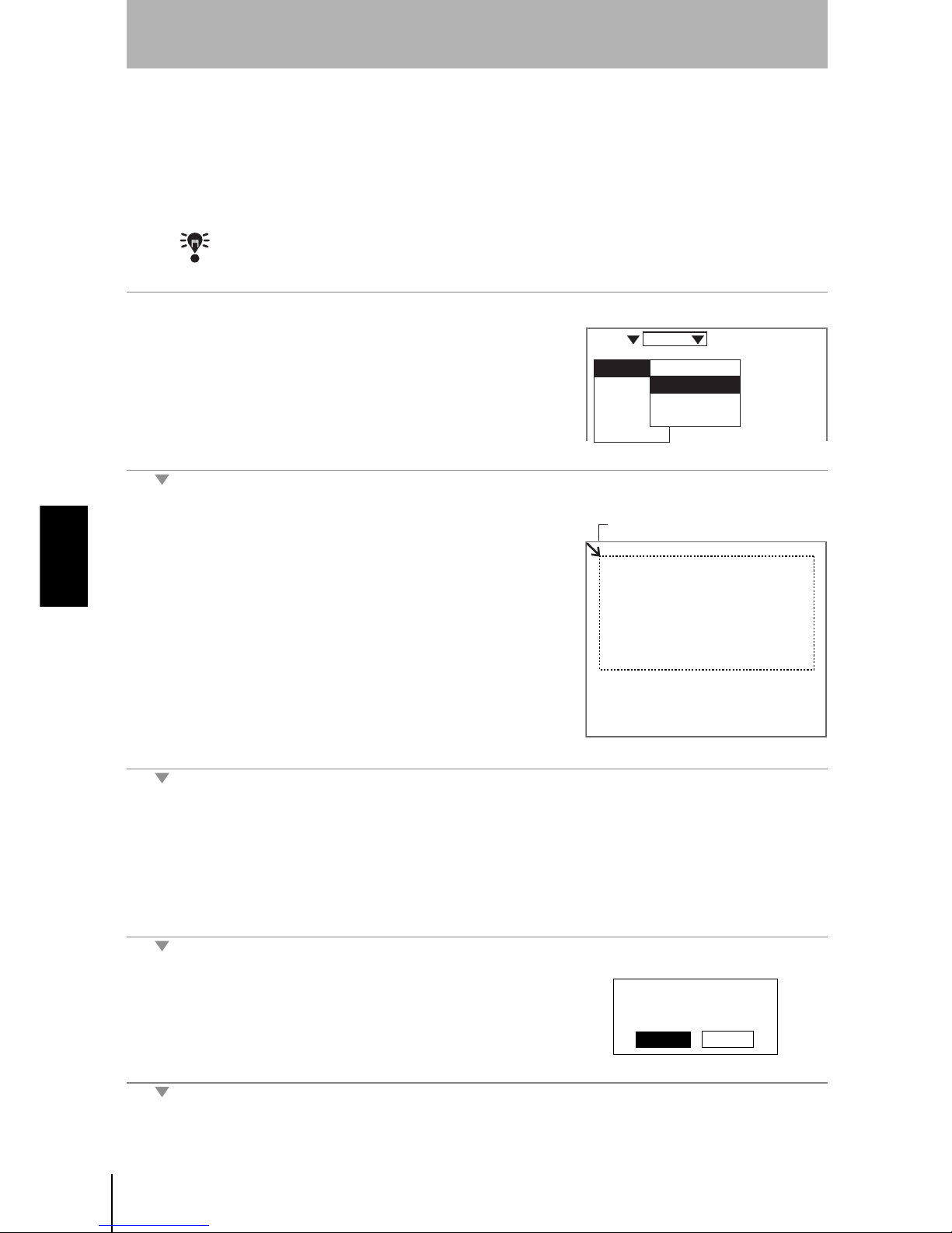
58
SECTION 4
4-1 Setting Measurement Conditions Using the Expert Menus
Z500
Operation Manual
SECTION 4
Menus for Expert Menu
Setting Measurement Region
Specify the region to be measured.
The Z500 adjusts sensitivity and performs measurements in a region that has
been previously set. Though the whole image can be used for the measurement
region, measurement accuracy can be raised by specifying a restricted
measurement region.
CHECK
Correct measurement may not be possible at the boundaries of the measurement regions.
Leave space at the boundaries when setting the regions.
1.
Select Image/Region.
The screen for specifying the region will be displayed.
2.
Specify the starting line of the
measurement region.
Move the cursor with the Up and Down
Keys.
(Use these keys together with the SHIFT
Key to move the cursor quickly.)
The cursor will be moved to the ending line.
3.
Repeat the procedure described in (2.) to specify the ending line of the
measurement region.
A confirmation message will be displayed.
4.
Select Execute.
The setting will be registered and the screen in (1.) will return.
Image
Compensatn
Meas set
Conditions
Output
Meas method
Region
Sensitivity
Details
Scn 0 Set
Cursor
The measurement region
will be set. OK?
Execute
Cancel
Page 61

59
Z500
Operation Manual
SECTION 4
SECTION 4
Menus for Expert Menu
Sensitivity Adjustment
Select the sensitivity adjustment method for the measurement range.
If the measurement results fluctuate, change the adjustment method.
Normally, these conditions can be left at the default settings.
CHECK
The setting can be performed through the adjustment menu.
REFERENCE
Refer to page 28.
Two Sensor
Select the Sensor number to be used for measurement.
Sensitivity Adjustment
The asterisk (*) indicates the default setting.
Sensitivity level (Displayed only when Fixed is selected from the
Sensitivity Menu)
Selection Description
Auto*
Adjust the sensitivity according to sensitivity information in the
measurement region.
Fixed
The sensitivity can be set to one of 31 levels (Setting range: 0 to 31).
Select when it is difficult to assure accurate measurement in Auto.
Such cases may appear on a production line where workpieces of
different colors are processed.
Multi
Adjust the sensitivity for each line in the measurement region.
Select when it is difficult to assure accurate measurement in Auto due to
a widely distributed brightness of the workpiece surfaces.
However, sampling time will be longer.
Position a reference workpiece and execute Multi. The Z500 will set
automatically the upper and lower limits of sensitivity on the basis of the
brightness of the reference workpiece.
After the settings have been completed, fine adjustment can be made on
Details.
REFERENCE
Refer to page 63.
Setting range
LV0 (See note
)
LV31 High
Bri
ght
Dark
Sensitivit
y
Color of workpiec
e
Note: The laser will turn OFF when selecting [LV0].
L
ow
Step
2
Step
1
Step
3
Step
4
Step
5
Step
6
Step
7
Page 62

60
SECTION 4
4-1 Setting Measurement Conditions Using the Expert Menus
Z500
Operation Manual
SECTION 4
Menus for Expert Menu
When selecting Auto
1.
Select Image/Sensitivity.
The selections for sensitivity adjustment will be displayed.
2.
Select Auto.
The setting will be registered and the screen in (1.) will return.
Image
Compensatn
Meas set
Conditions
Output
Meas method
Region
Sensitivity
Details
Scn 0 Set
Auto
Fixed
Multi
Page 63

61
Z500
Operation Manual
SECTION 4
SECTION 4
Menus for Expert Menu
When selecting Fixed
1.
Select Image/Sensitivity.
The selections for sensitivity adjustment will be displayed.
2.
Select Fixed.
The screen for setting the sensitivity level will be displayed.
3.
Select the level using the Up and
Down Keys while monitoring the
image on the monitor.
The level displayed first is the level
selected by the Z500 for the workpiece being measured. Adjust the
level while monitoring the line brightness graph and the received level on
the monitor.
120 max. : Insufficient light density
255 min. : Excessive light density
4.
Press the ENT Key.
The setting will be registered and the screen in (1.) will return.
Image
Compensatn
Meas set
Conditions
Output
Meas method
Region
Sensitivity
Details
Scn 0 Set
Auto
Fixed
Multi
DARK
FARNEAR
[ 15]
[ 170]
[ .]
[ ]
LV 15
Sen0
LV
PEAK
LV
PEAK
Sen1
BRIGHT
Line Brightness Received level
Step
2
Step
1
Step
3
Step
4
Step
5
Step
6
Step
7
Page 64

62
SECTION 4
4-1 Setting Measurement Conditions Using the Expert Menus
Z500
Operation Manual
SECTION 4
Menus for Expert Menu
When selecting Multi
1.
Select Image/Sensitivity.
The selections for sensitivity adjustment will be displayed.
2.
Select Multi.
The sensitivity multiple setting screen will be displayed.
3.
Check whether or not the workpiece
is positioned inside the measurement
range and press the ENT Key.
The setting will be registered and the screen in (1.) will return.
Image
Compensatn
Meas set
Conditions
Output
Meas method
Region
Sensitivity
Details
Scn 0 Set
Auto
Fixed
Multi
Scn 0 Set
Line beam image
Page 65

63
Z500
Operation Manual
SECTION 4
SECTION 4
Menus for Expert Menu
Details
Use this function to measure transparent workpieces. This function is also
useful to shorten the response time in Sensitivity/Multi. Normally, these
conditions can be left at the default settings. After changing the settings, perform
a workpiece measurement to check that measurement can still be performed
correctly.
The asterisk (*) indicates the default setting.
CHECK
The setting can be performed through the adjustment menu.
REFERENCE
Refer to page 28.
1.
Select Image/Details.
The setting screen for sensitivity details will be displayed.
2.
Make the settings for each item.
3.
Select End.
The setting will be registered and the screen in (1.) will return.
Item
Seleciton/
Setting range
Description
Surface
Frnt*
Back
The reflecting surface for which sensitivity adjustment
is performed is selected. To measure the back side of
a transparent workpiece, select Back. Normally (i.e.,
when measuring opaque workpieces), this setting can
be left as Frnt.
Upper 0 to 31(31*) Specify the range to be adjusted the sensitivity.
This function is effective when sensitivity adjustment
method is set to Auto or Multi. If the adjustment range
is small, the response time for switching sensitivity will
be short.
Lower 0 to 31(1*)
Gradations 120 to 220(170*)
Set the target gradation for sensor sensitivity
adjustment.
Image
Compensatn
Meas set
Conditions
Output
Meas method
Region
Sensitivity
Details
Scn 0 Set
Frnt
End
Surface
Upper
Lower
Gradations
:
:
:
:
[31]
[ 1]
[170]
Scn 0 Set
Step
2
Step
1
Step
3
Step
4
Step
5
Step
6
Step
7
Page 66

64
SECTION 4
4-1 Setting Measurement Conditions Using the Expert Menus
Z500
Operation Manual
SECTION 4
Menus for Expert Menu
Step 3
Position Compensation
The position compensation function is used when the position of the measurement workpieces are not
consistent.
By using this function, the displacement between the reference position and the current position is
obtained, and this displacement is compensated for in measurements. Compensation can be made for
both height and position.
• Reference Position
The measurement range and measurement workpiece are in the correct
positions.
• When the Position of the Workpiece is Lower
Height
Position
FARNEAR
[ 15]
[ 170]
[ .]
[ ]
9.96ms
BRIGHT
DARK
Sen0
LV
PEAK
LV
PEAK
Sen1
Scn 0 Run
Measurement point
LowHigh
Sensor
Workpiece
Measurement range
Measurement center
Height
FARNEAR
[ 15]
[ 170]
[ .]
[ ]
BRIGHT
DARK
9.96ms
Sen0
LV
PEAK
LV
PEAK
Sen1
Scn 0 Run
Measurement point
By making position displacement compensation settings ...
For measurement, compensate the height based on the displacement of the reference position.
Page 67

65
Z500
Operation Manual
SECTION 4
SECTION 4
Menus for Expert Menu
Operational Flow
CHECK
To use the position compensation function, set Compensatn and Meas set in this order.
#1
Registering the Reference Position
Register the position to be used for a reference for position compensation.
Before setting the necessary items, place the workpiece at the correct position.
In the example provided below, the procedure for compensating under the
following conditions is explained.
Reference height measurement point
Registering
the Reference
Position
#
1
Page 65
#
2
Page 69
Set the
Compensation
Method
Measurement
point (Average)
Reference height Reference position
Measurement
point (Edge position)
Region
Edge level
Selection Description
Average
Define the average profile position within a specified region as the
measurement point.
Peak
Define the peak profile position within a specified region as the
measurement point.
Bottom
Define the bottom profile position within a specified region as the
measurement point.
Region
Peak Bottom
Step
2
Step
1
Step
3
Step
4
Step
5
Step
6
Step
7
Page 68

66
SECTION 4
4-1 Setting Measurement Conditions Using the Expert Menus
Z500
Operation Manual
SECTION 4
Menus for Expert Menu
1.
Select Compensatn.
The selection for position compensation will be displayed.
2.
Select Reference.
A profile graph will be displayed.
3.
Check whether or not the workpiece
is positioned correctly and press the
ENT Key.
The screen for setting the reference height will be displayed.
4.
Specify the starting line of the
reference height region.
Use the Up and Down Keys to move
the cursor.
(Use these keys together with the
SHIFT Key to move the cursor
quickly.)
Image
Compensatn
Meas set
Conditions
Output
Scn 0 Set
Image
Compensatn
Meas set
Conditions
Output
None
Reference
Scn 0 Set
Profile
Measurement
region
Cursor
Page 69

67
Z500
Operation Manual
SECTION 4
SECTION 4
Menus for Expert Menu
The ending-line setting screen will be displayed.
5.
Specify the ending line of the reference
height region.
The characteristic quantity setting screen will be displayed.
6.
Select a characteristic quantity that can
be used as the measurement point of
the reference height.
The cross cursor of the measurement
point will move in response to the
selections.
Select the item while monitoring the image.
In this example, select Average.
The setting screen for reference position will be displayed.
7.
Specify the edge level to be used for the
reference position.
Use the Left and Right Keys to move
the cursor.
(Use these keys together with the SHIFT
Key to move the cursor quickly.)
Cursor
Average
Peak
Bottom
Cursor
Cursor
Step
2
Step
1
Step
3
Step
4
Step
5
Step
6
Step
7
Page 70

68
SECTION 4
4-1 Setting Measurement Conditions Using the Expert Menus
Z500
Operation Manual
SECTION 4
Menus for Expert Menu
A cross cursor to be used for specifying the reference height will
be displayed.
8.
Use the Up and Down Keys to select the
measurement point of the reference
position.
The cursor of the measurement point is
moved.
Select the measurement point while
monitoring the image.
A confirmation message will be displayed.
9.
Select Execute.
The setting will be registered and the screen in (2.) will return.
Cursor
Edge level
Reference will be
registered.
OK?
Execute Cancel Back
Page 71

69
Z500
Operation Manual
SECTION 4
SECTION 4
Menus for Expert Menu
#2
Set the Compensation Method
Select the position compensation method.
.
CHECK
Unless Reference has been set, the compensation method selections will not be
displayed.
1.
Move the cursor to None and press
the ENT Key.
The selection for compensation method will be displayed.
2.
Select the compensation method.
In this example, select Height&Pos.
The setting will be registered and the screen in (1.) will return.
Selection Description
None* No compensation is required.
Height Compensate the height.
Position Compensate the position.
Height&Pos Compensate both the height and position.
The asterisk (*) indicates the default setting.
Height
Position
Image
Compensatn
Meas set
Conditions
Output
None
Reference
Scn 0 Set
None
Height
Position
Height&Pos
Step
2
Step
1
Step
3
Step
4
Step
5
Step
6
Step
7
Page 72

70
SECTION 4
4-1 Setting Measurement Conditions Using the Expert Menus
Z500
Operation Manual
SECTION 4
Menus for Expert Menu
Step 4
Measurement Settings
Set the measurement contents. Operational flow varies depending on the measurement item.
Setting Step: 2 pts, Edge position, and Define are taken as examples for description.
Operational Flow
CHECK
To use the position compensation function, set Compensatn and Meas set in this order.
CHECK
The settings can be performed through the adjustment menu.
REFERENCE
Refer to page 28.
#1
Set Measurement Items
Up to eight measurement contents can be set for each scene.
There are 8 types of the measurement item. Different measurement item can be
set for each output number.
Types of Measurement Item
*Height is set in OUT0 as the default setting.
Set Output
Conditions
Changing
Measurement
Contents
Clearing
Measurement
Items
Set Measurement
Items
#1
Page 70
Page 86
Page 87
Set Calibration
#2
Page 78 (if necessary)
#3
Page 84 (if necessary)
When selecting
Define
:
When not
selecting
Define
:
#2
Calibration setting is disabled.
Compensate the measurements under the output conditions given in
#3.
Selection Description Symbol
Height* Measure the height within the specified region.
Step: 2 pts
Specify two measurement regions.
After taking the measurement point within the 1st region
as the reference, measure the distance from the measurement point in the 2nd region.
REFERENCE
Refer to page 72.
Step: 3 pts
Specify three measurement regions.
After taking the average of the measurement points
within the two regions specified above, measure the
difference from the measurement point in the 3rd region.
Edge position
Measures the specified edge position.
REFERENCE
Refer to page 74.
Page 73

71
Z500
Operation Manual
SECTION 4
SECTION 4
Menus for Expert Menu
Types of Measurement Item (Continued)
*Height is set in OUT0 as the default setting.
Characteristic Quantity of Measurement Points
Selection Description Symbol
Width
Measure the difference between the specified two edge
positions.
Edge center
Based on the specified two edge positions, measure the
center.
Peak/bottom
Measure the peak or bottom point of the height within
the specified region.
Define
Using the equation, set the measurement items.
The measurement result for an output number can be
assigned to the equation.
REFERENCE
Refer to page 76.
Selection Description
Average
Define the average profile position within a specified region as the
measurement point.
Peak
Define the peak profile position within a specified region as the
measurement point.
Bottom
Define the bottom profile position within a specified region as the
measurement point.
Back
Set the back side of the workpiece for the measurement point.
This procedure is effective when glass sheets and other transparent
workpieces are measured.
Region
Peak Bottom
Peak and Bottom
Surface
Back
Back
Workpiece
Step
2
Step
1
Step
3
Step
4
Step
5
Step
6
Step
7
Page 74

72
SECTION 4
Step: 2 pts
Z500
Operation Manual
SECTION 4
Menus for Expert Menu
Step: 2 pts
Level differences, grooves, etc. of workpieces are measured.
The following conditions will be taken as an example for describing the setting procedures.
1.
Select Meas set.
A list of output numbers will be displayed.
2.
Select the output number for which
Step: 2 pts is set.
In this example, Select OUT1.
CHECK
Height is set in OUT0 as the default set-
ting. To set an item other than Height in
OUT0, delete the existing measurement item.
REFERENCE
Refer to page 87.
The selection for measurement item will be displayed.
3.
Select the measurement item.
In this example, select Step: 2 pts.
Measurement
point (Average)
Measurement
point (Average)
Top face region
Bottom face region
Image
Compensatn
Meas set
Conditions
Output
Scn 0 Set
OUT0:Height
OUT1:
OUT2:
OUT3:
OUT4:
OUT5:
OUT6:
OUT7:
Scn 0 Set
Measrmnt item
Height
Step: 2 pts
Step: 3 pts
Edge position
Width
Edge center
Peak/bottom
Define
Page 75

73
Z500
Operation Manual
SECTION 4
SECTION 4
Menus for Expert Menu
The setting screen for bottom face measurement region will be
displayed.
4.
Specify the starting line of the bottom
face measurement region.
Move the cursor with the Up and Down
Keys.
(Use these keys together with the SHIFT
Key to move the cursor quickly.)
The ending-line setting screen will be displayed.
5.
Repeat the procedure described in (4.)
to specify the ending line of the bottom
face measurement region.
The characteristic quantity setting screen will be displayed.
6.
Select a characteristic quantity that can
be used as the measurement point of
the bottom face.
The cross cursor of the measurement
point will move in response to the
selections.
Select the item while monitoring the image.
In this example, select Average.
The setting screen for top face measurement region will be displayed.
7.
Repeat (4.) through (6.) to set the
characteristic quantities of the top face
measurement region and measurement
point.
A confirmation message will be displayed.
8.
Select Execute.
The setting will be registered and the screen in (2.) will return.
Cursor
Cursor
Average
Peak
Bottom
Back
Cursor
Measrmnt items will be set.
OK?
Execute Cancel Back
Step
2
Step
1
Step
3
Step
4
Step
5
Step
6
Step
7
Page 76
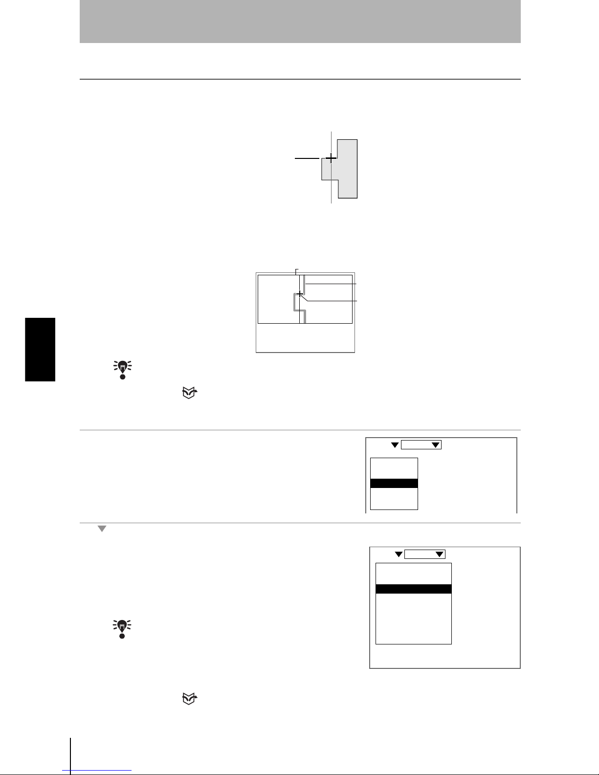
74
SECTION 4
Edge position
Z500
Operation Manual
SECTION 4
Menus for Expert Menu
Edge position
Measures the edge position of the workpiece.
The following conditions will be taken as an example for describing the setting procedures.
In this example, the intersection point of the edge level and the profile becomes
the measurement point.
Set the edge level as follows.
CHECK
The setting edge level and the measurement point can be checked on the Image Monitor.
REFERENCE
Refer to page 32.
1.
Select Meas set.
A list of output numbers will be displayed.
2.
Select the output number for which
Edge position is set.
In this example, select OUT2.
CHECK
Height is set in OUT0 as the default
setting. To set an item other than Height
in OUT0, delete the existing measurement item.
REFERENCE
Refer to page 87.
Measurement
point (Edge position)
Edge level
Edge level
Profile
The intersection is
the measurement point.
Image
Compensatn
Meas set
Conditions
Output
Scn 0 Set
OUT0:Height
OUT1:Step: 2 pts
OUT2:
OUT3:
OUT4:
OUT5:
OUT6:
OUT7:
Scn 0 Set
Page 77

75
Z500
Operation Manual
SECTION 4
SECTION 4
Menus for Expert Menu
The selection for measurement item will be displayed.
3.
Select the measurement item.
In this example, Select Edge position.
The setting screen for edge position will be displayed.
4.
Specify the level to be measured as the
edge.
Move the cursor with the Left and Right
Keys.
(Use these keys together with the SHIFT
Key to move the cursor quickly.)
The setting screen for edge position will be displayed.
5.
Specify the edge position regarded as
the measurement point.
Move the cursor with the Up and Down
Keys.
CHECK
In some cases, the cursor will not be
displayed on the intersection point of the
edge level and the edge position.
However, selection of an arbitrary cursor
will give the same measurement result
(the intersection point becomes the
measurement point), as long as the
selected cursor exists near the
intersection point.
A confirmation message will be displayed.
6.
Select Execute.
The setting will be registered and the screen in (2.) will return.
Measrmnt item
Height
Step: 2 pts
Step: 3 pts
Edge position
Width
Edge center
Peak/bottom
Define
Cursor
Measrmnt items will be set.
OK?
Execute Cancel Back
Step
2
Step
1
Step
3
Step
4
Step
5
Step
6
Step
7
Page 78

76
SECTION 4
Define
Z500
Operation Manual
SECTION 4
Menus for Expert Menu
Define
Set the equation by using the measurement results for the output number.
List of Items
Note 1
• Output number
When this item is selected, equation can be performed by using the
measurement results (results obtained after calibration) that have been set for
the output number.
CHECK
Any output number cannot be selected, unless its measurement items have been set.
Note 2
• Arithmetic Operators
Note 3
•Functions
OUT3
ABS
MAX
MIN
AVE
Cons
DEL
BS
Set
OUT1 OUT2
OUT0
OUT1
OUT2
OUT3
OUT4
OUT5
OUT6
OUT7
(
)
Output number for which
equation is set
Equation
List of Items
Select the items displayed
here for which equation is set.
Move the cursor.
Sets the equation.
Delete the items.
BS : Deletes the item to the left of the cursor.
DEL : Deletes the item to the right of the cursor.
Numerals between 0 and 9999999.999 can be set.
See note 2. See note 3.
See note 1.
ABS
MAX
MIN
AVE
Cons
DEL
BS
Set
OUT0
OUT1
OUT2
OUT3
OUT4
OUT5
OUT6
OUT7
(
)
Operator Meaning
+ Addition
- Subtraction
* Multiplication
/ Real number division
Function Description
ABS Calculates the absolute value. ABS (argument)
MAX
Gives the largest value of arguments. MAX (Argument 1, Argument 2,
Argument 3,…)
MIN
Gives the smallest value of arguments. MIN (Argument 1, Argument 2,
Argument 3,…)
AVE
Calculates the average value of arguments. AVE (Argument 1, Argument 2, Argument 3,…)
Page 79

77
Z500
Operation Manual
SECTION 4
SECTION 4
Menus for Expert Menu
1.
Select Meas set.
A list of output numbers will be displayed.
2.
Select the output number for which
Define is set.
In this example, select OUT3.
CHECK
Height is set in OUT0 as the default set-
ting. To set an item other than Height in
OUT0, delete the existing measurement
item.
REFERENCE
Refer to page 87.
The setting screen for equation will be displayed.
3.
Select the item from the list of items and
set the equation.
4.
Select Set when the equation has been
set.
A confirmation message will be displayed.
5.
Select Execute.
The setting will be registered and the screen in (2.) will return.
Image
Compensatn
Meas set
Conditions
Output
Scn 0 Set
OUT0:Height
OUT1:Step: 2 pts
OUT2:Edge position
OUT3:
OUT4:
OUT5:
OUT6:
OUT7:
Scn 0 Set
OUT3
ABS
MAX
MIN
AVE
Cons
DEL
BS
Set
OUT0
OUT1
OUT2
OUT3
OUT4
OUT5
OUT6
OUT7
(
)
Measrmnt items will be set.
OK?
Execute Cancel Back
Step
2
Step
1
Step
3
Step
4
Step
5
Step
6
Step
7
Page 80

78
SECTION 4
Define
Z500
Operation Manual
SECTION 4
Menus for Expert Menu
#2
Set Calibration
Set calibrations to compensate the measurement values. Set calibrations to compensate for differences
between measurement values and actual dimensions due to the color or material of the measurement
workpiece. The setting method varies depending on the measurement items set for the output number.
CHECK
Output can be used for fine adjustment after calibration setting. Use Output also to
compensate the measurement values when Define has been selected for the
measurement item.
REFERENCE
Refer to page 84.
CHECK
Refer to page 83 for information on how to clear calibration settings.
Compensate the Measured Height and Position
To compensate for the error, perform the measurement twice.
Applicable measurement items: Height, Edge position, Edge center,
Peak/bottom
Compensation Measurement items Description
Compensate the
measured height
and position.
Height, Edge position, Edge
center, Peak/bottom
For setting, repeat the measurement
twice.
REFERENCE
Refer to page 78.
Compensate the
measured level
difference and
width.
Step: 2 pts, Step: 3 pts, Width
For setting, repeat the measurement
once.
REFERENCE
Refer to page 81.
Calibrate to 10 mm.
10mm
10mm
9.95mm
Measurement of point 1
Measure without
the workpiece.
Measurement of point 2
Measure with the
workpiece in position.
Workpiece height: 10 mm
Use the method shown below to calibrate workpieces so that a displacement value of 9.95 mm is
measured as 10 mm.
Input the height
of point 2.
10mm
Input the height
of point 1.
0mm
Compensate for this error.
Measurement value
Displacement of workpiece
Example 1: When selecting
Height
Page 81

79
Z500
Operation Manual
SECTION 4
SECTION 4
Menus for Expert Menu
Height in Example 1 is taken here to describe the setting method.
Make the necessary adjustments when setting a different item.
1.
Move the cursor to Height and press the
ENT Key.
The selections will be displayed.
2.
Select Calibrate.
Calibrate to 5 mm.
5mm
5mm
4.95mm
Measurement of point 1
Measurement of point 2
Movement distance from the edge position: 5 mm
Use the method shown below to calibrate workpieces so that a displacement value of 4.95 mm is
measured as 5 mm.
Input the
position
of point 2.
5mm
Input the
position
of point 1.
0mm
Compensate for this error.
Measurement value
Workpiece Movement
Measure with the workpiece
at the reference position.
Example 2: When selecting
Edge position
Move the workpiece by 5 mm
for the measurement.
OUT0:Height
OUT1:Step: 2 pts
OUT2:Edge position
OUT3:Define
OUT4:
OUT5:
OUT6:
OUT7:
Scn 0 Set
Change
Calibrate
Output
Delete
Scn 0 Set
Step
2
Step
1
Step
3
Step
4
Step
5
Step
6
Step
7
Page 82

80
SECTION 4
Define
Z500
Operation Manual
SECTION 4
Menus for Expert Menu
A confirmation message will be displayed.
3.
Select Execute.
The measurement screen for point 1 will be displayed.
4.
Press the ENT Key without a workpiece
in position.
The screen for inputting the position of point 1 will be displayed.
5.
Set the value to 0.00000 and press the
ENT Key.
The measurement screen for point 2 will be displayed.
6.
Position the workpiece correctly and
press the ENT Key.
The screen for inputting the position of point 2 will be displayed.
7.
Set the value to 5.00000 and press the
ENT Key.
A confirmation message will be displayed.
8.
Select Execute.
The setting will be registered and the screen in (2.) will return.
System will be calibrated.
Clear settings now if
required.
Execute Cancel
Clear
00000.00000
00005.00000
System will be calibrated.
Execute Cancel
Page 83

81
Z500
Operation Manual
SECTION 4
SECTION 4
Menus for Expert Menu
Compensate the Measured Level Difference and Width
To compensate for the error, perform the measurement once.
Applicable measurement items: Step: 2 pts, Step: 3 pts, Width
1.
Move the cursor to Step: 2 pts and
press the ENT Key.
The selections will be displayed.
2.
Select Calibrate.
5mm
5mm
4.95mm
Measure with the
workpiece in position.
0mm
Compensate for this error.
Measurement value
Calibrate to 5 mm.
Point 1
Point 2
Level difference: 5 mm
Use the method shown below to calibrate workpieces so that a displacement value of 4.95 mm is
measured as 5 mm.
Input the value
of point 1.
5mm
Example : When selecting
Step: 2 pts
To compensate for this error, perform the measurement once.
Input the value
of point 2.
Level difference of workpiece
OUT0:Height
OUT1:Step: 2 pts
OUT2:Edge position
OUT3:Define
OUT4:
OUT5:
OUT6:
OUT7:
Scn 0 Set
Change
Calibrate
Output
Delete
Scn 0 Set
Step
2
Step
1
Step
3
Step
4
Step
5
Step
6
Step
7
Page 84

82
SECTION 4
Define
Z500
Operation Manual
SECTION 4
Menus for Expert Menu
A confirmation message will be displayed.
3.
Select Execute.
The measurement screen for point will be displayed.
4.
Position the workpiece correctly and
press the ENT Key.
The screen for inputting the position of point 1 will be displayed.
5.
Set the value to 0.00000 and press the
ENT Key.
The screen for inputting the position of point 2 will be displayed.
6.
Set the value to 5.00000 and press the
ENT Key.
A confirmation message will be displayed.
7.
Select Execute.
The setting will be registered and the screen in (2.) will return.
System will be calibrated.
Clear settings now if
required.
Execute Cancel
Clear
00000.00000
00005.00000
System will be calibrated.
Execute Cancel
Page 85

83
Z500
Operation Manual
SECTION 4
SECTION 4
Menus for Expert Menu
Clearing Calibration Settings
1.
Move the cursor to the measurement
item to be cleared and press the ENT
Key.
The selections will be displayed.
2.
Select Calibrate.
A confirmation message will be displayed.
3.
Select Clear.
The setting will be cleared and the screen in (2.) will return.
OUT0:Height
OUT1:Step: 2 pts
OUT2:Edge position
OUT3:Define
OUT4:
OUT5:
OUT6:
OUT7:
Scn 0 Set
Change
Calibrate
Output
Delete
Scn 0 Set
System will be calibrated.
Clear settings now if
required.
Execute Cancel
Clear
Step
2
Step
1
Step
3
Step
4
Step
5
Step
6
Step
7
Page 86

84
SECTION 4
Define
Z500
Operation Manual
SECTION 4
Menus for Expert Menu
#3
Set Output Conditions
Set the output conditions of measurement results as necessary.
The asterisk (*) indicates the default setting.
Span and Offset
CHECK
When calibration is executed, the span and the offset will be automatically set.
Item Selection Description
Upper
-9999.99999 to
9999.99999
Set the judgment conditions. Set the range for a PASS
judgment.
Lower
Hold
Set when the Trigger function is used. Select the contents of the data to
be held.
REFERENCE
For details on the Trigger function, refer to page 90.
None* Hold measurement is not performed.
Sampling The value at the start of measurement is held.
Peak
The highest value measured during measurement is
held.
Bottom The lowest value measured during measurement is held.
Peak-Peak
The difference between the highest and lowest values
measured during measurement is held.
Average
The average value between the highest and lowest
values measured during measurement is held.
Zero
-9999.99999 to
9999.99999
Set the offset value for force-zero execution.
Set the value to be added to 0.
REFERENCE
Refer to page 110, Force-zero.
Span
0.20000 to
4.00000
(1.00000*)
Set to make fine adjustments to measurement values
after calibration. Set for the incline in the Sensor
characteristics.
Offset
-9999.99999 to
9999.99999
(0.00000*)
Set to make fine adjustments to measurement values
after calibration. Added to or subtracted from
measurement values that have been set.
Unit
mm*
mm
2
None
Select the unit of the measured values to be displayed on
the monitor screen.
Measurement value
(mm)
Displacement
of workpiece
0.2
4.0
A coefficient (the span) is set to compensate
for incline in the Sensor characteristics.
Span
Measurement value
(mm)
Displacement
of workpiece
Offset
A fixed value (the offset) is added to or
subtracted from measurement values.
Page 87

85
Z500
Operation Manual
SECTION 4
SECTION 4
Menus for Expert Menu
1.
Move the cursor to the output number to
be set the output conditions and press
the ENT Key.
The selections will be displayed.
2.
Select Output .
The setting screen for output conditions will be displayed.
3.
Set the necessary items.
4.
Select End.
The setting will be registered and the screen in (2.) will return.
OUT0:Height
OUT1:Step: 2 pts
OUT2:Edge position
OUT3:Define
OUT4:
OUT5:
OUT6:
OUT7:
Scn 0 Set
Change
Calibrate
Output
Delete
Scn 0 Set
End
Upper
Lower
Hold
Zero
Span
Offset
Unit
:
:
:
:
:
:
:
[ 10.00000]
[ -10.00000]
None
[ 0.00000]
[1.00000]
[ 0.00000]
mm
Scn 0 Set
Step
2
Step
1
Step
3
Step
4
Step
5
Step
6
Step
7
Page 88

86
SECTION 4
Changing Measurement Contents
Z500
Operation Manual
SECTION 4
Menus for Expert Menu
Changing Measurement Contents
Change the measurement contents that have been set for the output number.
CHECK
To change measurement items, clear the existing measurement items and then
set new items.
REFERENCE
Refer to page 87.
1.
Move the cursor to the output number to
be changed the output conditions and
press the ENT Key.
The selections will be displayed.
2.
Select Change.
The setting screen for measurement range will be displayed.
The remaining procedures are the same as those for measurement item setting.
OUT0:Height
OUT1:Step: 2 pts
OUT2:Edge position
OUT3:
OUT4:
OUT5:
OUT6:
OUT7:
Scn 0 Set
Change
Calibrate
Output
Delete
Scn 0 Set
Page 89

87
Z500
Operation Manual
SECTION 4
SECTION 4
Menus for Expert Menu
Clearing Measurement Items
Clear the measurement items that have been set for the output numbers.
REFERENCE
Refer to page 127 for details on clearing separately for each scene.
1.
Move the cursor to the output number to
be cleared the output conditions and
press the ENT Key.
The selections will be displayed.
2.
Select Delete.
A confirmation message will be displayed.
3.
Select Execute.
The measurement items for the selected output number are cleared off and the screen in (1.) will return.
OUT0:Height
OUT1:Step: 2 pts
OUT2:Edge position
OUT3:Define
OUT4:
OUT5:
OUT6:
OUT7:
Scn 0 Set
Change
Calibrate
Output
Delete
Scn 0 Set
Delete OUT0 settings.
Execute Cancel
Step
2
Step
1
Step
3
Step
4
Step
5
Step
6
Step
7
Page 90

88
SECTION 4
Clearing Measurement Items
Z500
Operation Manual
SECTION 4
Menus for Expert Menu
Step 5
Measurement Conditions
Set the measurement conditions. The following can be set in Conditions and its lower hierarchies.
Perform the setting as required.
Averaging number
Use this function to disregard sudden changes in the waveform. The average of
the setting number of times is output as the measurement result.
The asterisk (*) indicates the default setting.
• The Relationship between the Measurement Response Time and the Resolution
CHECK
The setting can be performed through the adjustment menu.
REFERENCE
Refer to page 28.
1.
Select Conditions.
Menu Description Reference
# to avg
The average of the setting number of times is output as
the measurement result. Set this function to disregard
sudden changes in the waveform.
Page 88.
Trigger
From the measurement results that have been obtained
within a specified measurement period, the specified
characteristic quantity is held and output.
Page 90.
Details
Removing noises, outputting measurement failure, and
other miscellaneous methods can be set in more detail.
Page 96.
Selection
1, 2, 4, 8*, 16, 32, 64, 128, 256
Averaging
number
Short
1
256 Long
Low
High
Measurement
response time
Resolution
Image
Compensatn
Meas set
Conditions
Output
Scn 0 Set
Page 91

89
Z500
Operation Manual
SECTION 4
SECTION 4
Menus for Expert Menu
The selections will be displayed.
2.
Select # to avg.
The setting screen for averaging number will be displayed.
3.
Select averaging number.
4.
Select End.
The setting will be registered and the screen in (2.) will return.
# to avg
Trigger
Details
: 8
End
# to avg
Scn 0 Set
Step
2
Step
1
Step
3
Step
4
Step
5
Step
6
Step
7
Page 92
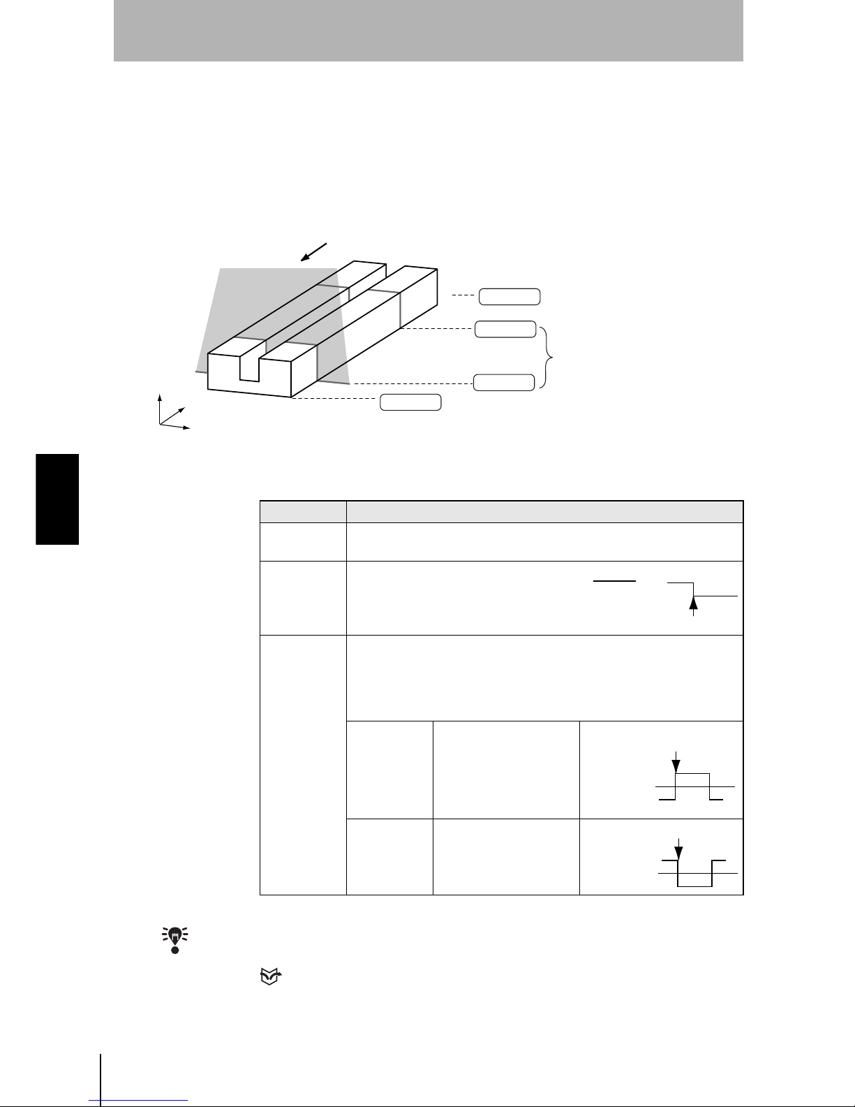
90
SECTION 4
Clearing Measurement Items
Z500
Operation Manual
SECTION 4
Menus for Expert Menu
Trigger setting
Use the Trigger function to measure moving workpieces in chronological order.
From the measurement results that have been obtained within a specified
measurement period, the specified characteristic quantity is held and output.
Use the procedure explained below to set the trigger input method.
• Trigger Input Method
The asterisk (*) indicates the default setting.
CHECK
Use Output to select the characteristic quantity that holds the measured values.
REFERENCE
Refer to page 84.
Start
Workpiece movement direction
Trigger ON
End
Trigger OFF
Position(mm)
Time(s)
Height(mm)
The characteristic quantities being
held are output at this timing.
The characteristic quantity of
the measurement during
this period will be held.
Selection Description
Free*
Measurement is performed continuously. Hold measurement is not
performed.
External
Select when using a sync sensor.
The trigger turns ON at the same time as
the TRIGGER terminal on the terminal
block.
Self
The trigger-ON timing is determined according to the measurement
value. The trigger turns ON when the measurement value goes above
(or below) the trigger level. If Self is selected, the screen for selecting
the output number (for the trigger setting) and the trigger direction is
displayed.
Up*
The trigger turns ON
when the measurement
value goes above the
trigger level.
Down
The trigger turns ON
when the measurement
value goes below the
trigger level.
Trigger ON
TRIGGER
terminal
OFF
ON
Trigger level
Trigger ON
Measurement
value waveform
Measurement
value waveform
Trigger level
Page 93

91
Z500
Operation Manual
SECTION 4
SECTION 4
Menus for Expert Menu
The procedure for make trigger settings under the following details is explained
below.
Operational Flow
#1
Display Waveforms in the Trend Monitor
Use the waveform to decide the trigger level and to set the measurement start
position.
CHECK
Set the screen mode to Thru in advance.
REFERENCE
Refer to page 118.
1.
Press the SHIFT + Right Keys or SHIFT
+ Left Keys several times to switch to
Trend Monitor.
2.
Pass the workpiece under the Sensor
and display the waveform.
3.
The instant the waveform representing
the workpiece is displayed, press the
TRIG Key.
The waveform display is fixed.
Trigger input method
Self
Hold setting (see note)
Peak-Peak
Measurement item
OUT0:Height
OUT0
Refer to page 84.
The difference between the maximum value and minimum value of the workpiece height is output.
Note:
Set the Hold setting by using
Meas set
in advance.
Display Waveforms
in the Trend Monitor
(Through Mode)
#1
Page 91
#2
Page 92
#3
Page 95
Confirm Trigger
Settings
Set the Trigger Input
Method
(Trigger Mode)
PASS
mm+0005.18800
Zero's OFF
OUT 0
Thru
9.96ms
S+ / :Display S+ENT:Adjust
Scn 0 Run
1div x: 1.000 [s]
y:+10.0000 [mm]
Thru
Scn 0 Set
The symbol changes.
1div x: 1.000 [s]
y:+10.0000 [mm]
Step
2
Step
1
Step
3
Step
4
Step
5
Step
6
Step
7
Page 94

92
SECTION 4
Clearing Measurement Items
Z500
Operation Manual
SECTION 4
Menus for Expert Menu
#2
Set the Trigger Input Method
Select the trigger input method, and set the trigger position and the trigger level.
CHECK
The setting can be performed through the adjustment menu.
REFERENCE
Refer to page 28.
1.
Enter Set Mode and select Conditions.
The selections will be displayed.
2.
Select Trigger.
The selections for trigger input method will be displayed.
3.
Select the trigger input method and
press the ENT Key.
In this example, select Self.
The setting screen for trigger contents will be displayed.
4.
Set each item.
In this example, select Trigger to OUT0
and Direction to Up.
5.
Select Execute.
The trigger setting screen will be
displayed.
The waveform set in
#1
is displayed.
Image
Compensatn
Meas set
Conditions
Output
Scn 0 Set
# to avg
Trigger
Details
Free
External
Self
:OUT0
:Up
Execute
Cancel
Trigger
Direction
Scn 0 Set
Free
External
Self
Page 95

93
Z500
Operation Manual
SECTION 4
SECTION 4
Menus for Expert Menu
6.
Specify the trigger-ON position and
trigger level, and press the ENT Key.
Use the Left and Right Keys to specify
the trigger position.
Use the Up and Down Keys to specify
the trigger level.
Use these Keys together with the SHIFT
Key to move the cursor quickly.
CHECK
When the trigger turns ON, the waveform above the trigger level is displayed at a position
based on the position set here.
The trigger-OFF setting screen will be displayed.
7.
Using the Left and Right Keys, specify
the trigger-OFF position.
Use the Left and Right Keys together
with the SHIFT Key to move the cursor
quickly.
The setting screen for measurement start timing will be
displayed.
8.
Using the Left and Right Keys, specify
the measurement starting position.
Use the Left and Right Keys together
with the SHIFT Key to move the cursor
quickly.
CHECK
The time for cursor position (time after
the trigger is turned ON) is displayed on
the lower part of the screen. Refer this
time for setting the measurement
starting position.
Thru
Trigger
Trigger-ON position
Trigger level
1div x: 1.000 [s]
y:+10.0000 [mm]
Trigger Position in the Center Trigger Position on the Left
The waveform before and
after the trigger turns ON
can be monitored.
Mainly the waveform after
the trigger turns ON can be
monitored.
Trigger
Thru
Trigger-OFF position
1div x: 1.000 [s]
y:+10.0000 [mm]
Thru
Trigger
Measure start 249.00 ms
Measurement start position
Time for cursor position
1div x: 1.000 [s]
y:+10.0000 [mm]
Step
2
Step
1
Step
3
Step
4
Step
5
Step
6
Step
7
Page 96

94
SECTION 4
Clearing Measurement Items
Z500
Operation Manual
SECTION 4
Menus for Expert Menu
The cursor will be moved to the measurement ending position.
9.
Repeat the procedure described in (8.)
to specify the measurement ending
position.
CHECK
The time for cursor position (time after
the trigger is turned ON) is displayed on
the lower part of the screen. Refer this
time for setting the measurement ending
position.
A confirmation message will be displayed.
10.
Select Execute.
The setting will be registered and the screen in (2.) will return.
Thru
Trigger
Measure start 249.00 ms
Measure stop 2320.68 ms
Measurement end position
Time for cursor position
1div x: 1.000 [s]
y:+10.0000 [mm]
The settings
will be changed.
OK?
Execute Cancel Back
Page 97

95
Z500
Operation Manual
SECTION 4
SECTION 4
Menus for Expert Menu
#3
Confirm Trigger Settings
Check if measurements are being correctly performed with the set trigger contents.
CHECK
Set the screen mode to Trig in advance.
REFERENCE
Refer to page 118.
1.
Press the SHIFT + Right Keys or SHIFT
+ Left Keys several times to switch to
Trend Monitor.
2.
Pass the workpiece under the Sensor.
The waveform is displayed from the trigger position set in #2.
3.
Perform a workpiece measurement
several times to check that
measurement can be performed
correctly.
• When the measurement start and end positions have to be adjusted
Return to the procedure in
#2
, with the waveform kept displayed, and adjust the
positions.
PASS
mm+0005.18800
Zero's OFF
OUT 0
Thru
9.96ms
S+ / :Display S+ENT:Adjust
Scn 0 Run
1div x: 1.000 [s]
y:+10.0000 [mm]
Trig
9.96ms
Scn 0 Run
Trigger-OFF positionTrigger-ON position
1div x: 1.000 [s]
y:+10.0000 [mm]
Step
2
Step
1
Step
3
Step
4
Step
5
Step
6
Step
7
Page 98

96
SECTION 4
Clearing Measurement Items
Z500
Operation Manual
SECTION 4
Menus for Expert Menu
Details setting
Use the details setting when measurement cannot be performed correctly or when more accurate
measurement is required.
1.
Select Conditions.
The selections will be displayed.
2.
Select Details.
The setting screen for details will be displayed.
3.
Make the settings for each item.
4.
Select End.
The setting will be registered and the screen in (2.) will return.
Image
Compensatn
Meas set
Conditions
Output
Scn 0 Set
# to avg
Trigger
Details
Scn 0 Set
End
:
:
:
:
:
:
:
:
None
2pixel
50.0%
Clamp
Intrpolate
1pixel
judgement width
Edge width
Smoothing
Noise
Level
Error data
Profile
Peak/btm width
[ 0.01000]
[ 0.00000]
Page 99

97
Z500
Operation Manual
SECTION 4
SECTION 4
Menus for Expert Menu
Judgment value hysteresis width (judgement width)
Set the hysteresis width for Judgment limits.
The default setting varies depending on the Sensor connected.
Edge Detection Hysteresis Width (Edge width)
Set the hysteresis width of edge detection.
Change the edge width when edge detection is unstable.
The asterisk (*) indicates the default setting.
Smoothing
(Smoothing)
Use this function to smooth the measured images.
The asterisk (*) indicates the default setting.
Noise removal
(Noise)
Other than images with a setting pixel will be regarded as noise and excluded
from measurement.
The asterisk (*) indicates the default setting.
Setting range
0.00000 to 9999.99999
HI
(100.0000)
LO
(80.0000)
HIGH
OFF
ON
OFF
ON
OFF
ON
LOW
PASS
Hysteresis(0.0500)
Hysteresis(0.0500)
Resets at 80.0500 mm
Output
Resets at 99.9500 mm
Example: HI: 100.000 mm; LO: 80.000 mm
Judgment value hysteresis width: 0.05 mm
Setting range
0.00000 to 9999.99999 (0.00000*)
Edge level
(80.0000)
Hysteresis (0.0500)
Edge position
Example: Edge level: 80.000 mm
Edge level hysteresis width: 0.0500 mm
Selection Description
None No smoothing.
Weak* Smoothing is performed at a low level.
Strong Smoothing is performed at a high level.
Selection
0pixel, 1pixel, 2pixel, 3pixel, 4pixel*, 5pixel, 6pixel, 7pixel,
Step
2
Step
1
Step
3
Step
4
Step
5
Step
6
Step
7
Page 100

98
SECTION 4
Clearing Measurement Items
Z500
Operation Manual
SECTION 4
Menus for Expert Menu
Measurement Level
(Level)
Change this when workpiece material fluctuation is too extensive to assure
correct measurement. Set the measurement level of the measurement height (a
percentage of the peak level of the line brightness). The default setting is 50.0%.
Normally, use this setting.
The asterisk (*) indicates the default setting.
Error data
(Error data)
In cases where the light density is temporarily excessive or insufficient (i.e.,
measurement is not possible) due to defects or holes in the workpiece, it is
possible to set the Z500 to hold the previous data.
The asterisk (*) indicates the default setting.
Selection
12.5%, 25.0%, 37.5%, 50.0%*, 62.5%, 75.0%, 87.5%,
Measurement level (i.e., Peak level Measurement level (%))
Peak level
Line Brightness
Set this value.
Measurement
level (50 %)
The peak measurement position can be adjusted by raising the measurement level.
Measurement
level (75 %)
The intermediate point between the measurement level edges
provides the height measurement result.
Selection Description
Clamp* An error is displayed and is output.
Hold
The value measured immediately before measurement became
impossible is displayed and output.
The previous data is held for parts where
measurement is not possible.
Operation with Hold Setting
The parts in the waveform corresponding to
the holes indicate measurement failure.
Measurement value
Time
Time
Operation with Clamp Setting
Measurement value
 Loading...