


Cat. No. SCHA-719A
Z4LB V2
Parallel Beam
Linear Sensor
INSTRUCTION MANUAL

READ AND UNDERSTAND THIS DOCUMENT
Please read and understand this document before using the
products. Please consult your OMRON representative if you
have any questions or comments.
WARRANTY
OMRON’s exclusive warranty is that the products are free
from defects in materials and workmanship for a period of
one year (or other period if specified) from date of sale by
OMRON.
OMRON MAKES NO WARRANTY OR REPRESENTATION, EXPRESS OR IMPLIED, REGARDING NON–INFRINGEMENT, MERCHANTABILITY, OR FITNESS FOR
PARTICULAR PURPOSE OF THE PRODUCTS. ANY BUYER OR USER ACKNOWLEDGES THAT THE BUYER OR
USER ALONE HAS DETERMINED THAT THE PRODUCTS
WILL SUITABLY MEET THE REQUIREMENTS OF THEIR
INTENDED USE. OMRON DISCLAIMS ALL OTHER WARRANTIES, EXPRESS OR IMPLIED.
LIMITATIONS OF LIABILITY
OMRON SHALL NOT BE RESPONSIBLE FOR SPECIAL,
INDIRECT, OR CONSEQUENTIAL DAMAGES, LOSS OF
PROFITS OR COMMERCIAL LOSS IN ANY WAY CONNECTED WITH THE PRODUCTS, WHETHER SUCH
CLAIM IS BASED ON CONTRACT, WARRANTY, NEGLIGENCE, OR STRICT LIABILITY.
In no event shall responsibility of OMRON for any act exceed the individual price of the product on which liability is
asserted.
IN NO EVENT SHALL OMRON BE RESPONSIBLE FOR
WARRANTY, REPAIR, OR OTHER CLAIMS REGARDING
THE PRODUCTS UNLESS OMRON’S ANALYSIS CON-

FIRMS THAT THE PRODUCTS WERE PROPERLY HANDLED, STORED, INSTALLED, AND MAINTAINED AND
NOT SUBJECT TO CONTAMINATION, ABUSE, MISUSE,
OR INAPPROPRIATE MODIFICATION OR REPAIR.
SUITABILITY FOR USE
THE PRODUCTS CONTAINED IN THIS DOCUMENT ARE
NOT SAFETY RATED. THEY ARE NOT DESIGNED OR
RATED FOR ENSURING SAFETY OF PERSONS, AND
SHOULD NOT BE RELIED UPON AS A SAFETY COMPONENT OR PROTECTIVE DEVICE FOR SUCH PURPOSES. Please refer to separate catalogs for OMRON’s
safety rated products.
OMRON shall not be responsible for conformity with any
standards, codes, or regulations that apply to the combination of products in the customer’s application or use of the
product.
At the customer’s request, OMRON will provide applicable
third party certification documents identifying ratings and
limitations of use that apply to the products. This information
by itself is not sufficient for a complete determination of the
suitability of the products in combination with the end product, machine, system, or other application or use.
The following are some examples of applications for which
particular attention must be given. This is not intended to be
an exhaustive list of all possible uses of the products, nor is
it intended to imply that the uses listed may be suitable for
the products:
• Outdoor use, uses involving potential chemical contamination or electrical interference, or conditions or uses not described in this document.
• Nuclear energy control systems, combustion systems, railroad systems, aviation systems, medical equipment, amuse-

ment machines, vehicles, safety equipment, and installations subject to separate industry or government regulations.
• Systems, machines, and equipment that could present a risk
to life or property.
Please know and observe all prohibitions of use applicable
to the products.
NEVER USE THE PRODUCTS FOR AN APPLICATION INVOLVING SERIOUS RISK TO LIFE OR PROPERTY WITHOUT ENSURING THAT THE SYSTEM AS A WHOLE HAS
BEEN DESIGNED TO ADDRESS THE RISKS, AND THAT
THE OMRON PRODUCT IS PROPERLY RATED AND
INSTALLED FOR THE INTENDED USE WITHIN THE
OVERALL EQUIPMENT OR SYSTEM.
PERFORMANCE DATA
Performance data given in this document is provided as a
guide for the user in determining suitability and does not
constitute a warranty. It may represent the result of OMRON’s test conditions, and the users must correlate it to actual application requirements. Actual performance is subject
to the OMRON Warranty and Limitations of Liability.
CHANGE IN SPECIFICATIONS
Product specifications and accessories may be changed at
any time based on improvements and other reasons.
It is our practice to change model numbers when published
ratings or features are changed, or when significant
construction changes are made. However, some specifications of the product may be changed without any notice.
When in doubt, special model numbers may be assigned to
fix or establish key specifications for your application on
your request. Please consult with your OMRON representative at any time to confirm actual specifications of purchased products.

DIMENSIONS AND WEIGHTS
Dimensions and weights are nominal and are not to be used
for manufacturing purposes, even when tolerances are
shown.
ERRORS AND OMISSIONS
The information in this document has been carefully
checked and is believed to be accurate; however, no responsibility is assumed for clerical, typographical, or proofreading errors, or omissions.
PROGRAMMABLE PRODUCTS
OMRON shall not be responsible for the user’s programming of a programmable product, or any consequence
thereof.
COPYRIGHT AND COPY PERMISSION
This document shall not be copied for sales or promotions
without permission.
This document is protected by copyright and is intended
solely for use in conjunction with the product. Please notify
us before copying or reproducing this document in any manner, for any other purpose. If copying or transmitting this
document to another, please copy or transmit it in its entirety.

Z4LB V2
Parallel Beam Linear Sensor
Instruction Manual

Notice:
OMRON products are manufactured for use according to proper procedures
by a qualified operator and only for the purposes described in this manual.
The following conventions are used to indicate and classify precautions in
this manual. Always heed the information provided with them. Failure to
heed precautions can result in injury to people or damage to property.
DANGER Indicates an imminently hazardous situation which, if not
!
avoided, will result in death or serious injury.
WARNING Indicates a potentially hazardous situation which, if not
!
avoided, could result in death or serious injury.
Caution Indicates a potentially hazardous situation which, if not
!
avoided, may result in minor or moderate injury, or property
damage.
Visual Aids
The following headings will help you locate different types of information.
Note Indicates information of particular interest for efficient and con-
venient operation of the product.
→ Indicates pages where additional information can be found.
1 Indicates a procedure. The step numbers in the procedure
correspond to the numbers in any related illustrations.
OMRON, 1999
All rights reserved. No part of this publication may be reproduced, stored in a retrieval system, or transmitted,
in any form, or by any means, mechanical, electronic, photocopying, recording, or otherwise, without the prior
written permission of OMRON.
No patent liability is assumed with respect to the use of the information contained herein. Moreover, because
OMRON is constantly striving to improve its high-quality products, the information contained in this manual is
subject to change without notice. Every precaution has been taken in the preparation of this manual. Nevertheless, OMRON assumes no responsibility for errors or omissions. Neither is any liability assumed for damages resulting from the use of the information contained in this publication.
iv

PRECAUTIONS ix. . . . . . . . . . . . . . . . . . . . .
1 Laser Safety x. . . . . . . . . . . . . . . . . . . . . . . . . . . . . . . . . . . .
2 Application Precautions xxi. . . . . . . . . . . . . . . . . . . . . . . . . .
3 Environment xxii. . . . . . . . . . . . . . . . . . . . . . . . . . . . . . . . . . .
4 Maintenance xxii. . . . . . . . . . . . . . . . . . . . . . . . . . . . . . . . . . .
5 General Precautions xxii. . . . . . . . . . . . . . . . . . . . . . . . . . . . . .
6 Checking the Package xxiii. . . . . . . . . . . . . . . . . . . . . . . . . . . .
SECTION 1
Application Example 1. . . . . . . . . . . . . . . . .
1-1 Inspection for Loose Bottle Caps 2. . . . . . . . . . . . . . . .
SECTION 2
Preparations 9. . . . . . . . . . . . . . . . . . . . . . . .
2-1 Nomenclature 10. . . . . . . . . . . . . . . . . . . . . . . . . . . . . . .
2-2 Wiring 14. . . . . . . . . . . . . . . . . . . . . . . . . . . . . . . . . . . . .
2-3 Connections 18. . . . . . . . . . . . . . . . . . . . . . . . . . . . . . . .
2-4 Axis and Gain Adjustments 18. . . . . . . . . . . . . . . . . . . .
2-5 Sensor Installation 19. . . . . . . . . . . . . . . . . . . . . . . . . . .
SECTION 3
Basic Settings 23. . . . . . . . . . . . . . . . . . . . . . . .
3-1 Selecting the Measurement Unit 24. . . . . . . . . . . . . . . .
3-2 Setting Thresholds 26. . . . . . . . . . . . . . . . . . . . . . . . . . .
SECTION 4
Optional Settings 35. . . . . . . . . . . . . . . . . . . . .
4-1 Optional Functions 36. . . . . . . . . . . . . . . . . . . . . . . . . . .
4-2 Key Settings 38. . . . . . . . . . . . . . . . . . . . . . . . . . . . . . . .
4-3 Selector Settings 47. . . . . . . . . . . . . . . . . . . . . . . . . . . . .
SECTION 5
Timing Charts 49. . . . . . . . . . . . . . . . . . . . . . .
5-1 Normal 50. . . . . . . . . . . . . . . . . . . . . . . . . . . . . . . . . . . .
5-2 Peak Hold 51. . . . . . . . . . . . . . . . . . . . . . . . . . . . . . . . . .
5-3 Bottom Hold 52. . . . . . . . . . . . . . . . . . . . . . . . . . . . . . . .
5-4 Sample Hold 53. . . . . . . . . . . . . . . . . . . . . . . . . . . . . . . .
5-5 Peak-to-peak Hold 54. . . . . . . . . . . . . . . . . . . . . . . . . . .
5-6 Self-peak Hold 55. . . . . . . . . . . . . . . . . . . . . . . . . . . . . .
5-7 Self-bottom Hold 56. . . . . . . . . . . . . . . . . . . . . . . . . . . .

SECTION 6
Troubleshooting 57. . . . . . . . . . . . . . . . . . . . .
SECTION 7
Specifications and Dimensions 59. . . . . . . . . .
7-1 Specifications 60. . . . . . . . . . . . . . . . . . . . . . . . . . . . . . .
7-2 Dimensions 64. . . . . . . . . . . . . . . . . . . . . . . . . . . . . . . . .

About this Manual:
This manual describes the installation and operation of the Z4LB V2 Parallel Beam Linear Sensor and includes the sections described below.
Please read this manual carefully and be sure you understand the information provided
before attempting to install and operate the Z4LB V2 Parallel Beam Linear Sensor.
Section 1 provides practical information on the connections, wiring, and operation of the
Z4LB V2 with a typical application example. Read this section for a quick application reference.
Section 2 provides information on preparations that must be made before turning ON the
Sensor, such as wiring, connecting, and installing Sensors and Amplifiers.
Section 3 provides information on basic settings, such as the threshold settings for good/
improper product discriminations.
Section 4 provides information on the optional functions that can be set in addition to the
basic settings.
Section 5 provides timing charts to show the operation of the hold modes.
Section 6 provides information on error messages and remedies to be taken. Refer to
this section before requesting service from your OMRON representative.
Section 7 provides the Sensor specifications and dimensions.
WARNING Failure to read and understand the information provided in this
!
manual may result in personal injury or death, damage to the
product, or product failure. Please read each section in its
entirety and be sure you understand the information provided
in the section and related sections before attempting any of
the procedures or operations given.
vii

PRECAUTIONS
This section provides general precautions for using the Z4LB V2 Parallel Beam Linear
Sensor.
The information contained in this section is important for the safe and reliable
application of the Z4LB V2 Parallel Beam Linear Sensor. You must read this section
and understand the information contained before attempting to set up or operate a
Z4LB V2 Parallel Beam Linear Sensor.
1 Laser Safety x. . . . . . . . . . . . . . . . . . . . . . . . . . . . . . . . . . . . .
2 Application Precautions xxi. . . . . . . . . . . . . . . . . . . . . . . . . . . .
3 Environment xxii. . . . . . . . . . . . . . . . . . . . . . . . . . . . . . . . . . . .
4 Maintenance xxii. . . . . . . . . . . . . . . . . . . . . . . . . . . . . . . . . . . .
5 General Precautions xxii. . . . . . . . . . . . . . . . . . . . . . . . . . . . . . .
6 Checking the Package xxiii. . . . . . . . . . . . . . . . . . . . . . . . . . . . .
ix
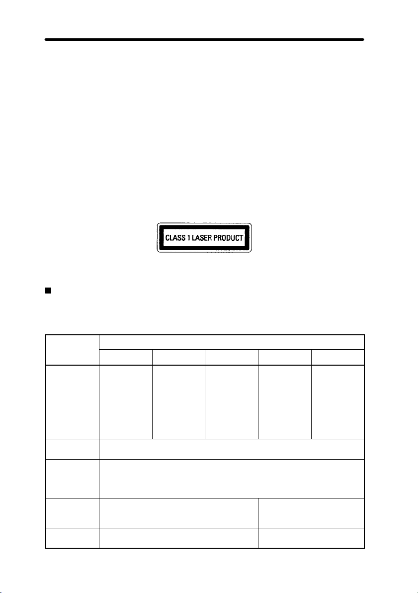
1 Laser Safety
The Z4LB V2 Parallel Beam Linear Sensor, is a Class 1 Laser Product according to
EN60825-1 (IEC825-1) and a Class II Laser Product according to FDA (21 CFR1040.10) (see
note). The Z4LB V2 is meant to be built into final system equipment. Pay special attention to
the following precautions for the safe use of the product:
Note: Europe: Class 1 of EN60825-1: 1994 = IEC825-1: 1993
U.S.A.: Class II of FDA (21 CFR1040.10)
1. Use this product as specified in this instruction manual. Otherwise, you may be exposed
to hazardous laser radiation.
2. Be careful not to expose your eyes directly to the laser radiation or indirectly to laser
radiation reflected from mirror or shiny surfaces.
3. To avoid exposure to hazardous laser radiation, do not displace nor remove the
protective housing during operation, maintenance, and any other servicing.
4. The user should return the product to OMRON for all repair and servicing.
5. As for other countries, observe the regulations and standards specified by each country.
Requirements from Regulations and Standards
EN60825-1 “Safety of Laser Products, Equipment Classification, Requirements and
User’s Guide”
Summary of Manufacturer’s Requirements
Require-
ments;
Sub-clause
Description
of hazard
class
Protective
housing
Safety interlock in protective housing
Remote control
Key control Not required Laser inoperative when key
Class 1 Class 2 Class 3A Class 3B* Class 4
Safe under
reasonably
foreseeable
conditions
Required for each laser product; limits access necessary for performance of functions of the products
Designed to prevent removal of the panel until accessible emission values are below the AEL (see note 2) for the class assigned
Not required Permits easy addition of ex-
Low power;
eye protection normally afforded
by aversion
responses
Classification
Same as
Class 2. Direct intrabeam viewing with optical aids may
be hazardous
Direct intrabeam viewing may be
hazardous
ternal interlock in laser
installation
is removed
High power;
diffused reflection may
be hazardous
1Laser Safety
x

1Laser Safety
Require-
ments;
ments;
Sub-clause
Sub-clause
Emission
warning device
Attenuator Not required Gives means beside ON/
Location
controls
Viewing optics
Scanning Scan failure shall not cause product to exceed its classification
Class label Required
Aperture label
Service
entry label
Override interlock label
User information
Purchasing
and service
information
Medical
products
Fibre optic Cable service connections require tool to disconnect if disconnection
* With respect to the requirements of remote interlock connector, key control, emission warn-
ing and attenuator, Class 3B laser products not exceeding five times the AEL of Class 2 in
the wavelength range of 400 nm to 700 nm are to be treated as Class 3A laser products.
Note: 1. This table is intended to provide a convenient summary of requirements. See text
Not required Gives audible or visible
Not required Controls so located that there is no danger
Emission from all viewing systems must be below Class 1 AEL’s as applicable
Figures A and B and specified wording
wording
Not required Specified wording required
Required as appropriate to the class of accessible radiation
Required under certain conditions as appropriate to the class of laser
used
Operation manuals must contain instructions for safe use
Promotion brochures must reproduce classification labels; service manuals must contain safety information
Special calibration instructions required Special calibration instruc-
breaks protective housing and permits access above Class 1
of this standard for complete requirements.
2. AEL: Accessible Emission Limit
The maximum accessible emission level permitted within a particular class.
For your reference, see ANSI Z136.1-1993, Section 2.
ClassificationRequire-
Class 4Class 3B*Class 3AClass 2Class 1
warning when laser is
switched on or if capacitor
bank of pulsed laser is being charged
OFF switch to temporarily
block beam
of exposure to AEL above Classes 1 or 2
when adjustments are made.
tions, means for measurement and target-indicator
required
xi

Symbol and border: black
Background: yellow
Figure A Warning label – Hazard symbol
Legend and border: black
Background: yellow
1Laser Safety
xii
Figure B Explanatory label

FDA (Compliance Guide for Laser Products, 1985, according to 21 CFR1040.10)
q
1Laser Safety
Requirements
I IIa II IIIa IIIb IV
Performance (all laser products)
Protective
housing
Safety interlock R (see
Location of controls
Viewing optics R R R R R R
Scanning safeguard
Performance (laser systems)
Remote control
connector
Key control N/A N/A N/A N/A R R
Emission indicator
Beam attenuator
Reset N/A N/A N/A N/A N/A R (see
Performance (specific purpose products)
Medical S S S S (see
Surveying, leveling, alignment
Demonstration S S S S S (see
Labeling (all laser products)
Certification &
identification
Protective
housing
Aperture N/A N/A R R R R
Class warning N/A R (see
Information (all laser products)
User information
Product literature
Service information
R (see
note 2)
notes 3,
4)
N/A R R R R
R R R R R R
N/A N/A N/A N/A R R
N/A N/A R R R (see
N/A N/A R R R R
S S S S NP NP
R R R R R R
D (see
note 5)
R R R R R R
N/A R R R R R
R R R R R R
R (see
note 2)
R (see
notes 3,
4)
D (see
note 5)
note 6)
Class (see note 1)
R (see
note 2)
R (see
notes 3,
4)
D (see
note 5)
R (see
note 7)
R (see
note 2)
R (see
notes 3,
4)
note 8)
D (see
note 5)
R (see
note 9)
R (see
note 2)
R (see
notes 3,
4)
note 10)
S (see
note 8)
note 11)
D (see
note 5)
R (see
note 12)
R (see
note 2)
R (see
notes 3,
4)
R (see
note 10)
note 13)
S (see
note 8)
(see
note 11)
D (see
note 5)
R (see
note 12)
xiii

Abbreviations:
R: Required.
N/A: Not applicable.
S: Requirements: Same as for other products of that Class.
Also see footnotes.
NP: Not permitted.
D: Depends on level of interior radiation.
Footnotes:
1. Based on highest level accessible during operation.
2. Required wherever & whenever human access to laser radiation above Class I limits is
not needed for product to perform its function.
3. Required for protective housings opened during operation or maintenance, if human
access thus gained is not always necessary when housing is open.
4. Interlock requirements vary according to Class of internal radiation.
5. Wording depends on level & wavelength of laser radiation within protective housing.
6. Warning statement label.
7. CAUTION logotype.
8. Requires means to measure level of laser radiation intended to irradiate the body.
9. CAUTION if 2.5 mW cm
10.Delay required between indication & emission.
11.Variance required for Class IIb or iV demonstration laser products and light shows.
12.DANGER logotype.
13.Required after August 20, 1986.
2
or less, DANGER if greater than 2.5 mW cm–2.
1Laser Safety
xiv

Use Precautions
EN60825-1
Require-
ments;
Sub-clause
Remote interlock
Key control Not required Remove key when not in
Beam attenuator
Emission indicator device
Warning
signs
Beam path Not required Terminate beam at end of useful length
Specular reflection
Eye protection
Protective
clothing
Training No requirements Required for all operator and maintenance
Class 1 Class 2 Class 3A Class 3B* Class 4
Not required Connect to room or door
Not required When in use prevents inad-
Not required Indicates laser is energized
Not required Follow precautions on
No requirements Prevent unintentional re-
No requirements Required if engineering and administrative
No requirements Sometimes
Classification
circuits
use
vertent exposure
warning signs
flections
procedures not practicable and MPE exceeded
required
personnel
Specific requirements
1Laser Safety
* With respect to the requirements of remote interlock connector, key control, beam attenua-
tor, and emission indicator, Class 3B laser products not exceeding five times the AEL of
Class 2 in the wavelength range of 400 nm to 700 nm are to be treated as Class 3A laser
products.
Note: This table is intended to provide a convenient summary of requirements. See text of
this standard for complete precautions.
xv

ANSI Z136.1:1993 “American National Standard for the Safe Use of Lasers”
Control Measures for the Four Laser Classes
1Laser Safety
Control measures
Engineering Controls 1 2a 2 3a 3b 4
Protective Housing
(4.3.1)
Without Protective Housing (4.3.1.1)
Interlocks on Protective
Housing (4.3.2)
Service Access Panel
(4.3.3)
Key Control (4.3.4) --- --- --- ---
Viewing Portals (4.3.5.1) --- --- MPE MPE MPE MPE
Collecting Optics
(4.3.5.2)
Totally Open Beam Path
(4.3.6.1)
Limited Open Beam Path
(4.3.6.2)
Enclosed Beam Path
(4.3.6.3)
Remote Interlock Connector (4.3.7)
Beam Stop or Attenuator
(4.3.8)
Activation Warning Systems (4.3.9)
Emission Delay (4.3.9.1) --- --- --- --- --- X
Indoor Laser Controlled
Area (4.3.10)
Class 3b Laser Controlled Area (4.3.10.1)
Class 4 Laser Controlled
Area (4.3.10.2)
Laser Outdoor Controls
(4.3.11)
Laser in Navigable Airspace (4.3.11.2)
Temporary Laser Controlled Area (4.3.12)
Remote Firing & Monitoring (4.3.13)
Labels (4.3.14 and 4.7) X X X X X X
Area Posting (4.3.15) --- --- ---
X X X X X X
LSO (see note 2) shall establish Alternate Controls
l l l l
l l l l
MPE MPE MPE MPE MPE MPE
--- --- --- --- X
--- --- --- --- X
None is required if 4.3.1 and 4.3.2 fulfilled
--- --- --- ---
--- --- --- ---
--- --- --- ---
--- --- --- --- X
--- --- --- --- X ---
--- --- --- --- --- X
--- --- --- --- X
--- --- ---
l
MPElMPElMPElMPE
--- --- --- --- ---
Classification
S S S
S
X X
X X
S
NHZ
NHZ
S
S
S
NHZ
NHZ
--- ---
X
NHZ
X
X
NHZ
X
NHZ
X
X
X
X
NHZ
X
NHZ
S
X
NHZ
xvi

Control measures Classification
Administrative & Procedural Controls
Standard Operating Procedures (4.4.1)
Output Emission Limitations (4.4.2)
Education and Training
(4.4.3)
Authorized Personnel
(4.4.4)
Alignment Procedures
(4.4.5)
Protective Equipment
(4.4.6)
Spectator (4.4.7) --- --- --- ---
Service Personnel (4.4.8)
Demonstration with General Public (4.5.1)
Laser Optical Fiber Systems (4.5.2)
Laser Robotic Installations (4.5.3)
Eye Protection (4.6.2) --- --- --- ---
Protective Windows
(4.6.3)
Protective Barriers and
Curtains (4.6.4)
Skin Protection (4.6.5) --- --- --- --- X
Other Protective Equipment (4.6.5)
Warning Signs and Labels (4.7) (Design Requirements)
Service and Repairs (4.8) LSO Determination
Modification of Laser
Systems (4.9)
1 2a 2 3a 3b 4
--- --- --- ---
--- --- --- LSO Determination
--- ---
--- --- --- --- X X
--- --- X X X X
--- --- --- ---
l
MPElMPElMPElMPE
MPE {
MPE MPE MPE MPE X X
--- --- --- --- X
--- --- --- --- X
--- --- --- ---
Use may be required
--- ---
LSO Determination
--- X X X X
S S
S S
S
X X
S
S
X X
NHZ
S
MPE
NHZ
S S
MPEX MPE
X
NHZ
X
X
X
X
NHZ
X
MPE
X
NHZ
X
NHZ
1Laser Safety
Note: 1. LEGEND
X: Shall
S: Should
---: No requirement
l: Shall if enclosed Class 3b or Class 4
MPE: Shall if MPE is exceeded
NHZ: Nominal Hazard Zone analysis required
{: Applicable only to UV and IR Lasers (4.5.1.2)
xvii

1Laser Safety
2. LSO: Laser Safety Officer
An individual shall be designated the Laser Safety Officer with the authority
and responsibility to monitor and enforce the control of laser hazards, and to
effect the knowledgeable evaluation and control of laser hazards.
For your reference, see ANSI Z136.1-1993, Section 1.3.
Laser Product Classifications
EN
Class
Class 1 Lasers which are safe under reasonably foreseeable conditions of opera-
tion.
Class 2 Lasers emitting visible radiation in the wavelength range from 400 nm to
700 nm. Eye protection is normally afforded by aversion responses including the blink reflex.
Class 3A Lasers which are safe for viewing with the unaided eye. For laser emitting
in the wavelength range from 400 nm to 700 nm, protection is afforded by
aversion responses including the blink reflex. For other wavelengths the
hazard to the unaided eye is no greater than for Class 1. Direct intrabeam viewing of Class 3A lasers with optical aides (e.g., binoculars, telescopes, microscopes) may be hazardous.
Class 3B Direct intrabeam viewing of these lasers is always hazardous. Viewing
diffuse reflections is normally safe (see note).
Class 4 Lasers which are also capable of producing hazardous diffuse reflections.
They may cause skin injuries and could also constitute a fire hazard.
Their use requires extreme caution.
Note: Conditions for safe viewing of diffuse reflections for Class 3B visible lasers are: mini-
mum viewing distance of 13 cm between screen and cornea and a maximum viewing
time of 10 s. Other viewing conditions require a comparison of the diffuse reflection
exposure with the MPE.
Description
xviii

Comparison of Classifications between FDA and ANSI
pp(
p
Class
Class
I/1
Class
IIa/2a
Class
II/2
Class
IIIa/3a
Class
IIIb/3b
Class
IV/4
Limits applicable to devices that have
emissions in the ultraviolet, visible, and
infrared spectra, and limits below which
biological hazards have not been established.
Limits applicable to products whose visible
emission does not exceed Class I limits for
emission durations of 1,000 seconds or
less and are not intended for viewing.
Limits applicable to products that have
emissions in the visible spectrum (400 to
710 nm) for emission durations in excess
of 0.25 second, providing that emissions
for other durations and/or wavelengths do
not exceed the Class I limits. Class II products are considered hazardous for direct
long-term ocular exposure.
Limits to products that have emissions in
the visible spectrum and that have beams
where the total collectable radiant power
does not exceed 5 milliwatts.
Limits applicable to devices that emit in the
ultraviolet, visible, and infrared spectra.
Class IIIb products include laser systems
ranging from 5 to 500 milliwatts in the visible spectrum. Class IIIb emission levels
are ocular hazards for direct exposure
throughout the range of the Class, and
skin hazards at the higher levels of the
Class.
Exceeding the limits of Class IIIb and are a
hazard for scattered reflection as well as
for direct exposure.
FDA definition ANSI description
1Laser Safety
A Class 1 laser is considered to
be incapable of producing damaging radiation levels during operation and maintenance and is,
therefore, exempt from any control measures or other forms of
surveillance.
Class 2 lasers are divided into
two subclasses, 2 and 2a. A
Class 2 laser emits in the visible
portion of the spectrum (0.4 to
0.7 µm) and eye protection is
normally afforded by the aversion response including the
blink reflex.
Class 3 lasers are divided into
two subclasses, 3a and 3b. A
Class 3 laser may be hazardous
under direct and specular reflection viewing conditions, but
the diffuse reflection is usually
not a hazard.
A Class 4 laser is a hazard to
the eye or skin from the direct
beam and sometimes from a diffuse reflection and also can be
fire hazard. Class 4 lasers may
also produce laser-generated
air contaminants and hazardous
plasma radiation.
xix
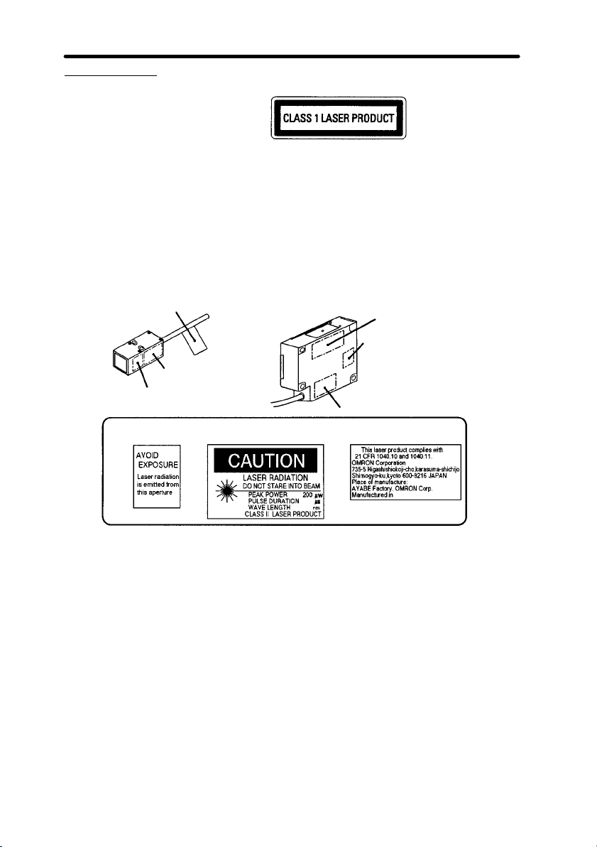
Label Indications
EN
FDA
Z4LB-S10V2
Z4LB-A1040jV2
1Laser Safety
Note Use of controls, adjustments, or procedures other
than those specified herein may result in hazardous
radiation exposure.
Z4LB-S30V2
Z4LB-A3040jV2
FDA Certification Label
FDA Caution Label
FDA Laser Aperture Label
FDA Laser
Aperture Label
Note Use of controls, adjustments, or procedures other
FDA Certification Label
FDA Laser Aperture Label
FDA Caution Label
FDA Caution Label FDA Certification Label
44
650
than those specified herein may result in hazardous
radiation exposure.
xx
2 Application Precautions
1. Users must operate the product according to the procedures and specifications
described in this manual. (Refer to 7-1 Specifications.)
2. Do not connect or disconnect a connector between the Sensor and Controller when the
power is turned ON, otherwise the Sensor may be damaged.
3. Warm up the Z4LB V2 for approximately 5 minutes after turning ON the power.
Power Supply and Wiring
1. Do not impose voltage exceeding the rated voltage, otherwise the Sensor may be
damaged.
2. When supplying power to the sensor, make sure that the polarity of the power is correct,
otherwise, the sensor may be damaged.
3. Do not short-circuit the load supplied with open collector output, otherwise the Sensor
may be damaged.
4. The Z49-C13 Extension Cable (3 or 8 m in length) can be connected to the sensor
cables or amplifier cables. The total length of the sensor cables or amplifier cables,
however, must be 10 m or less. Use a shielded cable to extend the amplifier cable, in
which case, a shielded cable that is the same as that of the amplifier cable must be used.
5. Do not lay a power supply cable for the Z4LB V2 together with high-voltage lines or
power lines to prevent interference, damage, and malfunction.
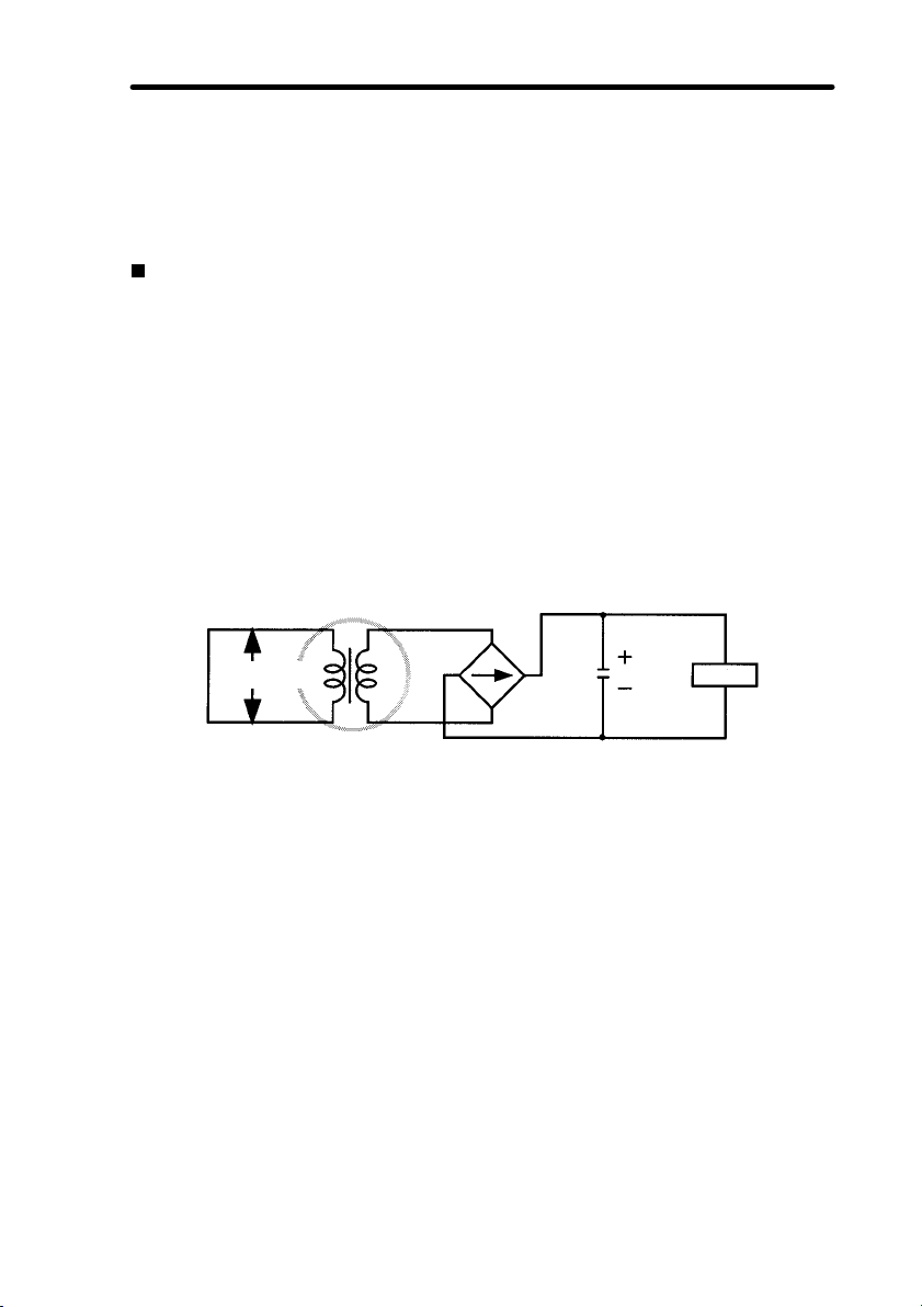
6. Use an isolation transformer for the power supply of the Z4LB V2 as shown in the
following.
2Application Precautions
Commercial
power supply
Isolation transformer
7. When using a switching regulator, use a FG (frame ground) terminal as a ground.
Z4LB V2
xxi

3 Environment
1. Do not use the Sensor in strong electromagnetic fields or in an environment where the
operation of the Sensor is subject to the reflection of intense light (such as other laser
beams or electric arc-welding machine.)
2. The Sensor cannot accurately detect the following types of objects:
• Mirror-like objects
• Transparent objects
• Objects with an extremely low reflection ratio
• Objects smaller than the Sensor’s sensing spot diameter
• Largely inclined objects
3. Do not install the Z4LB V2 in locations subject to the following conditions:
• Direct vibration or shock
• Direct sunlight or heaters
• High humidity
• Dust, salt, or iron particles
• Corrosive or flammable gasses
• Water, oil, or chemical fumes or spray
• Strong magnetic or high-voltage fields
• Condensation due to rapid temperature fluctuations
• Icing due to low temperature
4 Maintenance
1. Turn OFF the power when making adjustments or removing the Sensor.
2. Install the Sensor in a clean environment and keep the filter on the front panel of the
Sensor free from oil and dust. If affected by oil or dust, clean the filter as follows:
• Use a blower brush (used to clean camera lenses) to blow large dust particles from the
surface. Do not blow the dust away with your mouth.
• Use a soft cloth (for lenses) with a small amount of alcohol to remove the remaining
dust. Do not use a scrubbing action when cleaning as scratches on the filter could result in the Sensor malfunctioning.
• Do not use thinner or benzene. They will damage the optical characteristics of a filter.
5General Precautions
5 General Precautions
The user must operate the product according to the performance specifications described in
the instruction manual.
Consult your OMRON representative before using the product under conditions which are not
described in the manual or applying the product to nuclear control systems, railroad systems,
aviation systems, vehicles, combustion systems, medical equipment, amusement machines,
safety equipment, and other systems, machines, and equipment that may have a serious influence on lives and property if used improperly.
Make sure that the ratings and performance characteristics of the product are sufficient for the
systems, machines, and equipment, and be sure to provide the systems, machines, and
equipment with double safety mechanisms.
xxii

6 Checking the Package
When the product package is delivered, check if the package contains the following items. Although careful attention has been paid to packing the product, please contact your OMRON
representative if any item is found to be missing.
Standard Models (Separate Type)
Product Model Packing items
Sensor
Amplifier Z4LB-CV2
One-side Interruption High-precision Models (Integrated Type)
Z4LB-A1040V2
Z4LB-A1040PV2
Z4LB-A3040V2
Z4LB-A3040PV2
Z4LB-S10V2
Z4LB-S30V2
Z4LB-CPV2
Model Packing items
j One Z4LB-S10V2 Sensor
j Two mounting brackets
j Four M3 screws (25-mm long)
j Four M3 nuts
j Five labels
j One Z4LB-S30V2 Sensor
j Two mounting brackets
j Six M4 screws (25-mm long)
j Five labels
j One Z4LB-CV2 or Z4LB-CPV2
Amplifier
j One instruction manual (this manual)
j One screwdriver
j One Z4LB-A1040V2, Z4LB-A1040PV2,
Z4LB-A3040V2, or Z4LB-A3040PV2 Sensor
j One instruction manual (this manual)
j Five labels
6Checking the Package
xxiii

SECTION 1
Application Example
This section provides practical information on the connections, wiring, and operation of the
Z4LB V2 with a typical application example. Read this section for a quick application reference.
1-1 Inspection for Loose Bottle Caps 2. . . . . . . . . . . . . . . . .
1-1-1 Wiring and Connections 3. . . . . . . . . . . . . . . . . . . . .
1-1-2 Axis and Gain Adjustments 4. . . . . . . . . . . . . . . . . .
1-1-3 Setting Measurement Unit 5. . . . . . . . . . . . . . . . . . .
1-1-4 Setting Thresholds 6. . . . . . . . . . . . . . . . . . . . . . . . .
1-1-5 Detection 8. . . . . . . . . . . . . . . . . . . . . . . . . . . . . . . .
1
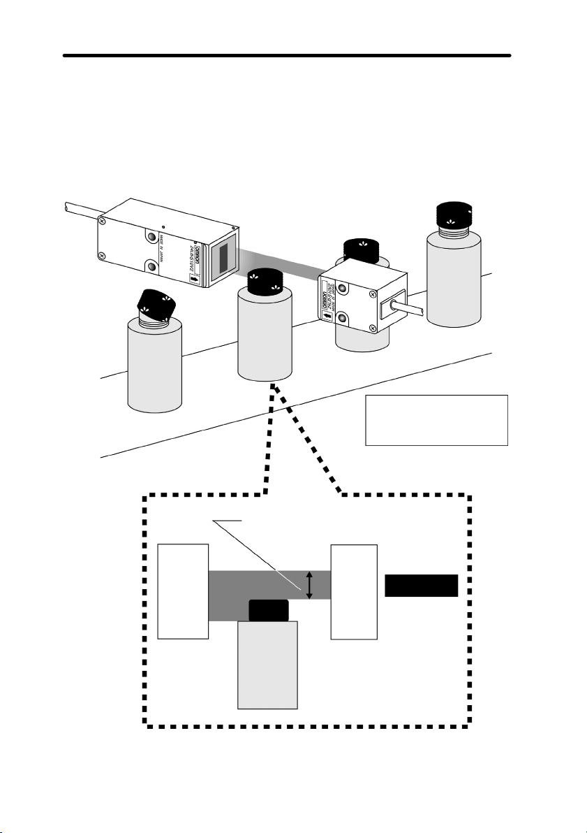
1-1 Inspection for Loose Bottle Caps
In this application, the height of the cap of each bottle is inspected to see if the caps are loose.
Example
Sensor: Z4LB-S10V2
Amplifier: Z4LB-CV2
1-1SectionInspection for Loose Bottle Caps
The amount of light incident on the receiver is detected.
Emitter
Good
product
Receiver
2
Operation Flow
Item Applicable Sensors
1-1-1 Wiring and Connections Standard and One-side
1-1-2 Axis and Gain Adjustments Standard
1-1-3 Setting Measurement Unit Standard
1-1-4 Setting Thresholds Standard and One-side
1-1-5 Detection Standard and One-side
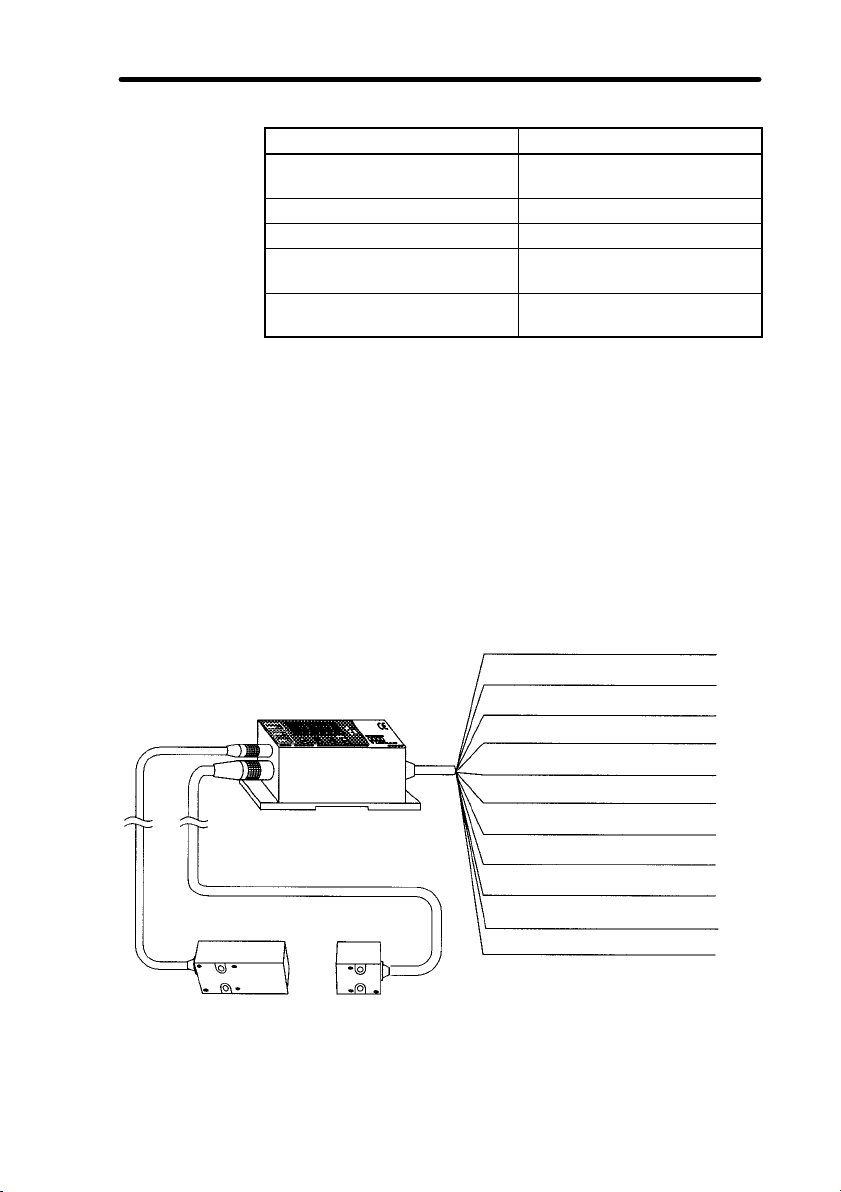
1-1-1 Wiring and Connections
The following information is the same for both Standard and
One-side Interruption High-precision Sensors.
1 Wire and connect the sensor components as shown below.
V/mm → Refer to 2-2 Wiring (p. 14) and 2-3 Connections (p. 18).
1-1SectionInspection for Loose Bottle Caps
Interruption High-precision
Interruption High-precision
Interruption High-precision
Amplifier
Emitter Receiver
2 Turn ON the power.
Brown (12 to 24 VDC)
Blue (0 V)
White (HIGH/PASS output)
Gray (LOW/NG output)
Black (1- to 5-V linear output)
Shield (Linear GND)
Green (Bank selection input)
Purple (Timing input)
Red (Hold reset input)
Orange/Purple (Forced-zero input)
Pink (LD OFF input)
3

1-1-2 Axis and Gain Adjustments
The following information is for Standard Sensors only.
Adjust the laser axis and gain according to the sensing distance.
1 Set the selectors on the Amplifier as shown below.
2 Closely attach the emitter and the receiver with the name-
plates of both the emitter and the receiver facing the same
direction.
1-1SectionInspection for Loose Bottle Caps
3 Use the provided screwdriver and turn the gain adjuster so
that the display on the Amplifier reads 5.000 ± 0.1 V.
Turn clockwise
or counterclockwise
4 Mount the emitter and the receiver in the desired positions.
Secure the receiver and tentatively secure the emitter.
5 Change the angle of the emitter upwards, downwards, left,
and right with no sensing object and secure the position of
the emitter at the angle where the maximum value is displayed.
6 Turn the gain adjuster so that the display reads
5.000 ± 0.005 V.
4

1-1-3 Setting Measurement Unit
The following information is for Standard Sensors only.
The measurement unit can be set to linear output voltage (V) or
length (mm). In the following example, the unit is set to mm.
Display
Set the measurement unit selector to mm. The Sensor is now
ready to display in millimeters.
Checking Measurement Width
Display
1-1SectionInspection for Loose Bottle Caps
1 Press the TEACH and SET Keys simultaneously for 3 s.
The present measurement width will be displayed.
2 Press the SET Key.
The Sensor will return to RUN mode.
Note If the displayed width is different from the measured width,
change the measurement width of the Amplifier. Otherwise the
linear output voltage will not be converted into length correctly.
→ Refer to Z4LB-S30V2 under 3-1 Selecting the Measure-
ment Unit (p. 24).
5

1-1-4 Setting Thresholds
The following information is the same for both Standard and
One-side Interruption High-precision Sensors.
Set the thresholds for good/improper product discrimination.
There are three methods to set the thresholds. The following description provides information on setting the thresholds by teaching based on a reference workpiece.
→ Refer to 3-2 Setting Thresholds (p. 26).
Example
No cap
Measured value
(Incident light)
1-1SectionInspection for Loose Bottle Caps
Discrimination
indicators
HIGH threshold
LOW threshold
Emitter
Emitter
Emitter
Improper
product
Normal
Good
product
Cap rise
Improper
product
Receiver
Receiver
Receiver
Lit
Not lit
6

1-1SectionInspection for Loose Bottle Caps
HIGH indicator
LOW indicator
HIGH Threshold Setting
1 Set the operating mode selector to H.
The HIGH indicator will start flashing and the present HIGH
threshold will be displayed.
2 Set the workpiece and press the TEACH Key.
Teaching will be performed. The teaching value plus an
approximate value of 0.7% F.S. (see note) will be displayed
as the HIGH threshold.
Note “F.S.” stands for full scale. In the case of the Z4LB-S10V2, for ex-
ample, the F.S. value is 10 mm.
Teaching value of reference workpiece
Display
HIGH threshold
Fine Adjustment of Values
The thresholds that are taught are reference values that can
be changed to desired values. Go to step 3 to change the
thresholds, otherwise go to step 5.
3 Press the Right Key to move the cursor to the digit to be
changed.
The selected
digit flashes.
4 Press the Up Key and change the value.
05.000 06.000 07.000
05.000 05.000
7

5 Press the SET Key.
The set value will be entered and the value will flash twice.
LOW Threshold Setting
6 Set the operating mode selector to L.
The LOW indicator will start flashing and the present LOW
threshold will be displayed.
7 Take steps similar to 2 and 5 to set the LOW threshold.
The LOW threshold obtained from the teaching value minus
an approximate value of 0.7% F.S. will be displayed.
Teaching value of reference workpiece
1-1-5 Detection
The following information is the same for both Standard and
One-side Interruption High-precision Sensors.
1-1SectionInspection for Loose Bottle Caps
LOW threshold
Set the operating mode selector to RUN.
The Sensor will start taking measurements and the indicator will
turn ON at the preset threshold value.
8

SECTION 2
Preparations
This section provides information on preparations that must be made before turning ON the
Sensor, such as wiring, connecting, and installing Sensors and Amplifiers.
2-1 Nomenclature 10. . . . . . . . . . . . . . . . . . . . . . . . . . . . . . . .
2-1-1 Standard Sensors (Separate Type) 10. . . . . . . . . . . . .
2-1-2 One-side Interruption High-precision Sensors
2-2 Wiring 14. . . . . . . . . . . . . . . . . . . . . . . . . . . . . . . . . . . . . .
2-2-1 I/O Signals 14. . . . . . . . . . . . . . . . . . . . . . . . . . . . . . .
2-2-2 I/O Stage Circuit Diagrams 16. . . . . . . . . . . . . . . . . .
2-3 Connections 18. . . . . . . . . . . . . . . . . . . . . . . . . . . . . . . . .
2-4 Axis and Gain Adjustments 18. . . . . . . . . . . . . . . . . . . . .
2-5 Sensor Installation 19. . . . . . . . . . . . . . . . . . . . . . . . . . . .
2-5-1 Sensors 19. . . . . . . . . . . . . . . . . . . . . . . . . . . . . . . . . .
2-5-2 Amplifiers 21. . . . . . . . . . . . . . . . . . . . . . . . . . . . . . . .
(Integrated Type) 12. . . . . . . . . . . . . . . . . . . . . . . . . .
9

2-1 Nomenclature
2-1-1 Standard Sensors (Separate Type)
Z4LB-S10V2 (Sensor)
2-1SectionNomenclature
Emitter
Z4LB-S30V2 (Sensor)
Emitter
Receiver
Receiver
10

NPN: Z4LB-CV2 (Amplifier)
PNP: Z4LB-CPV2 (Amplifier)
2-1SectionNomenclature
Operating
mode selector
LD ON indicator
(Laser emission
warning)
Discrimination
indicators
Measurement unit selector (p. 24)
Light/dark mode selector (p. 47)
Response time selector (p. 48)
Display
Operation keys
OFF delay selector (p. 48)
Forced-zero
indicator
(p. 31)
Gain adjuster
(p. 18)
11

2-1-2 One-side Interruption High-precision Sensors
(Integrated Type)
NPN: Z4LB-A1040V2 (Sensor)
PNP: Z4LB-A1040PV2 (Sensor)
Emitter Receiver
2-1SectionNomenclature
12
NPN: Z4LB-A3040V2 (Sensor)
PNP: Z4LB-A3040PV2 (Sensor)
Emitter
Receiver

NPN: Z4LB-Ajj40V2 (Amplifier)
PNP: Z4LB-Ajj40PV2 (Amplifier)
2-1SectionNomenclature
LD ON indicator
(Laser emission
warning)
Discrimination
indicators
Measurement unit selector (p. 24)
Light/dark mode selector (p. 47)
Response time selector (p. 48)
Display
Operation keys
OFF delay selector (p. 48)
Forced-zero
indicator
(p. 31)
Operating
mode selector
13

2-2 Wiring
2-2-1 I/O Signals
2-2SectionWiring
Brown
Blue
White
Gray
Black
Shield
Green
Purple
Red
Orange/Purple
Pink
(1) 12 to 24 VDC
(2) 0 V
(3) HIGH/PASS output
(4) LOW/NG output
(5) Linear output (1 to 5 V)
(6) Linear GND
(7) Bank selection input
(8) Timing input
(9) Hold reset input
(10) Forced-zero input
(11) LD OFF input
(1)12 to 24 VDC
Power terminal. Connect to 12 to 24 VDC power supply.
(2)0 V
0 V power terminal. Also, common terminals for forced zero
input, timing input, and LD OFF input.
(3)HIGH Output
Turns ON when the measured value is less than or equal to
the HIGH threshold. (Depends on the discrimination output
methods.)
PASS Output
Turns ON when the measured value is above the LOW
threshold and below the HIGH threshold. (Depends on the
discrimination output methods.)
(4)LOW Output
Turns ON when the measured value is equal to or greater
than the LOW threshold. (Depends on the discrimination
output methods.)
NG Output
Turns ON when the measured value is equal to or less than
the LOW threshold or equal to or greater than the HIGH
threshold. (Depends on the discrimination output methods.)
(5)Linear Output (1 to 5 V)
Outputs 1 to 5 VDC in proportion to light received or interrupted. (Selectable with light/dark mode switch)
(6)Linear GND
Connect to input device as linear output GND.
14

(7)Bank Selection Input
Selects the thresholds to use for measurement.
Bank 1
NPN: Open or connect to 1.
PNP: Open or connect to 2.
Bank 2
NPN: Connect to 2.
PNP: Connect to 1.
(8)Timing Input
Forcibly turns HIGH/PASS output and LOW/NG output OFF
if timing input is turned ON during normal measurement operations. The sampling timing turns ON if the timing input is
turned ON during hold measurement operation. ON or OFF
input time is set to 0.25 ms or more.
(9)Hold Reset Input
Resets the value held in memory if turned ON during hold
measurement operation. ON or OFF input time is set to
0.25 ms or more.
(10)Forced-zero Input
Zero will be displayed for the measured value if forced-zero
input is turned ON when the length (mm) is displayed on the
display. The value will be set if forced-zero input is ON for
0.2 to 0.8 s and cleared if it is input for 1 s or more.
(11)LD OFF Input
Stops laser emission. “ldoff” will be displayed on the display. The linear output, HIGH/LOW indicator, and the discrimination outputs will maintain the current status.
Warm up for 5 min after releasing LD OFF. The response
time required to turn laser emission ON or OFF is 30 ms.
2-2SectionWiring
→ Refer to 4-2-2 Selecting the Discrimination Outputs (p. 39).
15

2-2-2 I/O Stage Circuit Diagrams
NPN Sensors
Standard Sensor: Z4LB-CV2
One-side Interruption High-precision Sensors: Z4LB-AjjV2
Brown
100 Ω
Black
1- to 5-V linear output
2-2SectionWiring
Internal circuits
Shield
White
Gray
Blue 0 V
Pink
Purple
Red
Orange/Purple
Green
Linear output GND
HIGH/PASS output
LOW/NG output
Load
Load
30 VDC
max.
LD OFF input
Timing input
Hold reset input
Forced-zero input
Bank selection input
12 to 24 VDC
16

PNP Sensors
2-2SectionWiring
Standard Sensor: Z4LB-CPV2
One-side Interruption High-precision Sensors: Z4LB-AjjPV2
Brown
100 Ω
Black
1- to 5-V linear output
Internal circuit
Shield
White
Gray
Blue 0 V
Pink
Purple
Red
Orange/Purple
Green
Linear output GND
HIGH/PASS output
LOW/NG output
Load
Load
LD OFF input
Timing input
Hold reset input
Forced-zero input
Bank selection input
12 to
24
VDC
17

2-3 Connections
Connect the connector cables from the emitter and the receiver
to the side of the Amplifier as below. The connection method is
the same for Standard and One-side Interruption High-precision
Sensors.
Amplifier
Emitter Receiver
2-4 Axis and Gain Adjustments
After installing the emitter and the receiver for a Standard Sensor, adjust the laser axis and gain according to the sensing distance. No axis or gain adjustment is required for One-side Interruption High-precision Sensors because proper axis and gain
adjustments are made before shipping.
Procedure
1 Set the selectors on the Amplifier as shown below.
2-3SectionConnections
18

2-5SectionSensor Installation
2 Closely attach the emitter and the receiver with the name-
plates of both the emitter and the receiver facing the same
direction.
3 Use the provided screwdriver and turn the gain adjuster so
that the display on the Amplifier reads 5.000 ± 0.1 V.
Turn clockwise
or counterclockwise
4 Mount the emitter and the receiver in the desired position.
Secure the receiver and tentatively secure the emitter.
5 Change the angle of the emitter upwards, downwards, left,
and right with no sensing object and secure the position of
the emitter at the angle where the maximum value is displayed.
6 Turn the gain adjuster so that the display reads
5.000 ± 0.005 V.
2-5 Sensor Installation
2-5-1 Sensors
Caution Do not touch the optical filter of a Sensor. If it is stained with finger
!
prints or other material, measurements may not be performed
correctly. If you touch the filter by mistake, clean it with a soft
cloth.
19

Z4LB-S10V2 Sensor
Screws (M3, Length: 25, provided)
2-5SectionSensor Installation
1 Screw the mounting brackets to the emitter and the receiver.
The same mounting bracket is used for both the emitter and
the receiver.
Nuts (M3, provided)
2 Secure the mounting brackets.
Screws (M3)
→ Refer to 7-2 Dimensions for mounting dimensions (p. 64).
Z4LB-S30V2 Sensor
Emitter Receiver
Screws
(M4, Length 25, provided)
20
1 Screw the mounting brackets to the emitter and the receiver.
The same mounting bracket is used for the emitter and the
receiver, but the screw holes are different.
Screws
(M4, Length 25, provided)

2 Secure the mounting brackets.
Screws (M4)
→ Refer to 7-2 Dimensions for mounting dimensions (p. 64).
Z4LB-Ajj40V2/Z4LB-Ajj40PV2 Sensors
There are two mounting holes, one on the right and one on the
left. Screw the holes to install and secure the emitter and the receiver. When installed, the head of screws should not enter the
beam.
2-5SectionSensor Installation
Screws (M4)
→ Refer to 7-2 Dimensions for mounting dimensions (p. 64).
Note Do not disconnect the coupling bracket that connects the receiv-
er and the emitter, otherwise proper measurement will not be
possible.
2-5-2 Amplifiers
There are two mounting holes. Insert the screws into the holes to
install the Amplifier. The Amplifier can also be mounted to DIN
Track.
Screws (M4)
→ Refer to 7-2 Dimensions for mounting dimensions (p. 64).
21

SECTION 3
Basic Settings
This section provides information on basic settings, such as the threshold settings for good/
improper product discriminations.
3-1 Selecting the Measurement Unit 24. . . . . . . . . . . . . . . . .
3-2 Setting Thresholds 26. . . . . . . . . . . . . . . . . . . . . . . . . . . .
3-2-1 Direct Setting Thresholds 27. . . . . . . . . . . . . . . . . . . .
3-2-2 Teaching Thresholds 29. . . . . . . . . . . . . . . . . . . . . . .
3-2-3 Forced-zero Setting 31. . . . . . . . . . . . . . . . . . . . . . . .
23

3-1 Selecting the Measurement Unit
The measurement unit can be set to linear output voltage (V) or
length (mm). In the following example, the unit is set to mm.
Display
Set the measurement unit selector to mm.
The Sensor will display in millimeters.
Z4LB-S30V2 Sensor
The default setting for the measurement width of the Z4LB-CV2
Amplifier and Z4LB-CPV2 Amplifier is 10 mm. The measurement width of the Z4LB-S30V2 is 30 mm. Therefore, if the Z4LBCV2 or Z4LB-CPV2 Amplifier is connected to the Z4LB-S30V2,
the Amplifier cannot convert a linear output voltage range between 1 and 5 V into length correctly unless the measurement
width of the Amplifier is changed to 30 mm. There is no need to
change the measurement width for a One-side Interruption Highprecision Sensor.
Note Before using the Z4LB-S10V2 Sensor, check that the measure-
ment width is set to 10 mm. Refer to steps 1, 2, and 4.
3-1SectionSelecting the Measurement Unit
24

Checking and Changing the Measurement Width
Display
1 Set the operating mode selector to RUN.
2 Press the TEACH and SET Keys simultaneously for 3 s.
The present measurement width will be displayed.
(The default setting is 10.)
3 Press the Up Key twice and change the value from 1 to 3.
3-1SectionSelecting the Measurement Unit
The value 1 flashes.
10
Press the Up Key.
20
Press the Up Key.
30
4 Press the SET Key.
The set value will be entered and the indicator will flash
twice.
25

3-2 Setting Thresholds
Set the thresholds for good/improper product discrimination.
3-2SectionSetting Thresholds
Example
HIGH threshold
LOW threshold
No cap
Emitter
Normal
Emitter
Cap rise
Emitter
Measured value
(Incident)
Receiver
Receiver
Receiver
Measured value > HIGH threshold:
Improper product
LOW threshold < Measured value <
HIGH threshold: Good product
Measured value < HIGH threshold:
Improper product
Note The discrimination outputs can be changed. Refer to 4-2-2 Se-
lecting the Discrimination Outputs for details (p. 39).
26
Example
There are three methods to set thresholds. Select the most convenient method according to the application.
1 Direct Settings: The thresholds are set directly.
2 Teaching Settings: The thresholds are set based on a refer-
ence workpiece.
Measured value: 4 V
The LOW threshold is set.
The HIGH threshold is set.

3 Forced-zero settings: A measured value based on a refer-
ence workpiece is set as zero. Add or subtract a tolerance
directly to and from the reference value (zero) to set the results as thresholds.
The LOW threshold is set.
The HIGH threshold is set.
Note Discrimination outputs use HIGH and LOW threshold hysteresis
values. Refer to 4-2-3 Hysteresis Setting for the relationship between discrimination output ON/OFF points and thresholds.
→ Refer to Discrimination Outputs Timing Charts (p. 40).
3-2-1 Direct Setting Thresholds
The following method is convenient if the threshold value for discriminating good/improper products is known because values
are input directly in this method.
3-2SectionSetting Thresholds
HIGH indicator
LOW indicator
HIGH Threshold Setting
1 Set the operating mode selector to H.
The display will show the present HIGH threshold and the
HIGH indicator will flash. If the bank selection is enabled, the
bank number will be displayed.
→ Refer to 4-2-5 Enabling the Bank Selection (p. 44).
Display
27

3-2SectionSetting Thresholds
2 Press the Right Key to move the cursor to the value to be
changed.
The cursor will shift to the right by one digit whenever the
Key is pressed.
The selected value flashes.
3 Press the Up Key to change the value.
The value will increase by 1 whenever the Key is pressed.
4 Press the SET Key.
The value will be entered and the indicator will flash twice.
LOW Threshold Setting
5 Set the operating mode selector to L.
The LOW indicator will flash and the display will show the
present LOW threshold.
6 Take steps similar to 2 and 4 to set the LOW threshold.
00.000
Press the Right Key.
00.000
Press the Right Key.
00.000
00.000
Press the Up Key.
00.100
Press the Up Key.
00.200
28

3-2-2 Teaching Thresholds
3-2SectionSetting Thresholds
HIGH indicator
LOW indicator
HIGH Threshold Setting
1 Set the operating mode selector to H.
The display will show the present HIGH threshold and the
HIGH indicator will flash. If the bank selection is enabled, the
bank number will be displayed.
→ Refer to 4-2-5 Enabling the Bank Selection (p. 44).
2 Set the workpiece and press the TEACH Key.
Teaching will be performed. The HIGH threshold obtained
from the teaching value plus an approximate value of 0.7%
F.S. will be displayed.
Teaching value of reference workpiece
Display
HIGH threshold
Fine Adjustment of Values
The thresholds after teaching are reference values that can
be changed to desired values. Go to step 3 to change the
thresholds, otherwise go to step 5.
29

3-2SectionSetting Thresholds
3 Press the Right Key to move the cursor to the value to be
changed.
The cursor will shift to the right by one digit whenever the
Key is pressed.
The selected value flashes.
4 Press the Up Key and change the value.
The value will increase by 1 whenever the Key is pressed.
02.746
02.846
02.946
5 Press the SET Key.
The value will be entered and the indicator will flash twice.
02.746
Press the Right Key.
02.746
Press the Right Key.
02.746
Press the Up Key.
Press the Up Key.
LOW Threshold Setting
6 Set the operating mode selector to L.
The LOW indicator will flash and the display will show the
present LOW threshold.
7 Take steps similar to 2 and 5 to set the LOW threshold.
The teaching value minus an approximate value of 0.7% FS
will be displayed as the LOW threshold.
Teaching value of reference workpiece
30
LOW threshold

3-2-3 Forced-zero Setting
To set the thresholds, a measured value based on a reference
workpiece is first set as zero. A tolerance is then added to and
subtracted from the reference value (zero) to set the results as
HIGH and LOW thresholds. Forced-zero settings are possible
only if the unit is set to mm.
The HIGH and LOW thresholds are kept on hold when the reference workpiece is changed, which enables easy changeovers.
Thresholds are displayed between –9.999 and F.S. (see note),
but the linear output voltage will not change.
Note 1 “F.S.” stands for full scale. In the case of the Z4LB-S10V2,
for example, the F.S. value is 10 mm.
2 Forced-zero Indicator
When the forced-zero settings are enabled, the forced-zero
indicator will turn ON.
Forced zero is set.
SET
3 s
3-2SectionSetting Thresholds
05.697 00.000.
HIGH indicator
LOW indicator
Display Unit Selection
1 Set the measurement unit selector to mm.
Reference Value Setting
2 Set the operating mode selector to RUN.
3 Set the workpiece and press the SET Key for 3 s.
The forced-zero indicator will turn ON, when the measured
value will be set as the reference value (0).
The forced-zero indicator will turn ON.
Forced-zero indicator
Display
31

• Clearing Forced-zero Settings
• Forced-zero settings are possible through the forced-zero
Note When forced-zero settings are enabled, HIGH or
HIGH Threshold Setting
4 Set the operating mode selector to H.
The HIGH indicator will flash and the display will show the
present HIGH threshold.
5 Press the Right Key to move the cursor to the value to be
changed.
The cursor will shift to the right by one digit whenever the
Key is pressed.
3-2SectionSetting Thresholds
To clear the forced-zero settings, press the SET value for
3 s.
input terminal. The value is set if forced-zero input is ON
for 0.2 to 0.8 s and cleared if it is input for 1 s or more.
LOW threshold cannot be set by teaching. Add or
subtract a tolerance directly to and from the reference value (zero) to set the results as thresholds.
32
The selected value flashes.
00.000
Press the Right Key.
00.000
Press the Right Key.
00.000
6 Press the Up Key and set the tolerance to be added to the
reference value.
The value will increase by 1 whenever the Key is pressed.
00.000
Press the Up Key.
00.100
Press the Up Key.
00.200
7 Press the SET Key.

The value will be entered and the indicator will flash twice.
LOW Threshold Setting
8 Set the operating mode selector to L.
The LOW indicator will flash and the display will show the
present LOW threshold.
9 Take steps similar to steps 5 and 7 to set the LOW threshold.
Displaying Negative Values
80.500
Press the Up Key.
90.500
Press the Up Key.
Ć0.050
Bank Selection
If the bank selection is enabled, the screen to select the bank
number appears after the operating mode selector is set to H or
L. Set the thresholds after setting the bank number.
3-2SectionSetting Thresholds
Locate the cursor to the leftmost digit
and press the Up Key until the value
changes to 9.
Press the Up Key once again. The
negative symbol will appear.
Procedure
→ Refer to 4-2-5 Enabling the Bank Selection (p. 44).
1 Set the operating mode selector to H or L.
The bank number will be displayed and the HIGH or LOW
indicator will flash.
2 Press the Up Key and select the bank number where the
threshold will be set.
bank1 bank2
Bank 1 Bank 2
3 Press the SET Key.
The bank number will be entered and the display will show
the present threshold.
4 Set the HIGH or LOW thresholds.
33

SECTION 4
Optional Settings
This section provides information on the optional functions that can be set in addition to the
basic settings.
4-1 Optional Functions 36. . . . . . . . . . . . . . . . . . . . . . . . . . . .
4-2 Key Settings 38. . . . . . . . . . . . . . . . . . . . . . . . . . . . . . . . .
4-2-1 Setting the Measurement Width (scale)38. . . . . . . .
4-2-2 Selecting the Discrimination Outputs (oUt)39. . . . . .
4-2-3 Hysteresis Setting (hys)40. . . . . . . . . . . . . . . . . . . . .
4-2-4 Display/Output Value Hold (hold)42. . . . . . . . . . . .
4-2-5 Enabling the Bank Selection (bank)44. . . . . . . . . . .
4-2-6 Enabling Backup (baUp)45. . . . . . . . . . . . . . . . . . . .
4-2-7 Initialization (reset)46. . . . . . . . . . . . . . . . . . . . . . .
4-3 Selector Settings 47. . . . . . . . . . . . . . . . . . . . . . . . . . . . . .
4-3-1 Light/Dark Mode 47. . . . . . . . . . . . . . . . . . . . . . . . . .
4-3-2 Response Time Selection 48. . . . . . . . . . . . . . . . . . . .
4-3-3 OFF Delay 48. . . . . . . . . . . . . . . . . . . . . . . . . . . . . . .
35

4-1 Optional Functions
y
The optional settings are made with the selectors or operation
keys on the Amplifier.
Setting method Function Display Page
Key
Selectors
Measurement width
Discrimination outputs
Hysteresis setting
Hold
Bank selection
Backup
Initialization
Light/dark mode selection --- 47
Response time selection --- 48
OFF delay --- 48
Measurement unit selection --- 24
scale
oUt
hys
hold
bank
baUp
reset
38
39
40
42
44
45
46
4-1SectionOptional Functions
36

Function Settings with Keys
Press TEACH+SET Keys for 3 s.
Press TEACH Key for 3 s.
scale
Measurement width
4-1SectionOptional Functions
10
Run
mode
out
Discrimination outputs
hĆl1
pass
hĆl2
hys
Hysteresis setting Display unit: V Display unit: mm
hold
Hold
0.020 00.050
norml
pĆh
bĆh
sĆh
ppĆh
bank
Bank selection
spĆh
sbĆh
off
on
1.000
Display unit: V Display unit: mm
1.000
Display unit: V Display unit: mm
00.000
00.000
banp
Backup
reset
Initialization
on
off
All set value initialized
* Shaded settings are the default settings.
37

4-2 Key Settings
4-2-1 Setting the Measurement Width (scale)
The following settings are required only if the Z4LB-S30V2 Sensor is to be used with the measurement unit set to mm.
The following steps make it possible to change the measurement width. For details, refer to 3-1 Selecting the Measurement
Unit.
→ Refer to Z4LB-S30V2 Sensor under 3-1 Selecting the Mea-
surement Unit (p. 24).
Procedure
There are two procedures that can be used to set thresholds. Select the easier method according to the application. The following
example shows how to set the measurement width in function
selection mode.
1 Set the operating mode selector to RUN.
2 Press the TEACH Key for 3 s.
The Sensor will enter function selection mode.
3 Press the Up Key to go to measurement width setting.
scale
Measurement width
4-2SectionKey Settings
The figure 1 flashes.
38
4 Press the SET Key.
5 Press the UP Key twice to change 1 to 3.
10 20 30
6 Press the SET Key.
The set value will be entered and the display will flash twice.
7 Press the TEACH Key to return to RUN mode.

4-2-2 Selecting the Discrimination Outputs (oUt)
There are three methods to discriminate and output measurement data. Select the best method for the application.
1 HIGH/LOW Output Mode (hĆl1)
Measured value x HIGH threshold: HIGH output ON
Measured value y LOW threshold: LOW output ON
2 PASS/NG Output Mode (pass)
LOW threshold < Measured value < HIGH threshold:
PASS output ON
Measured value x LOW threshold or
Measured value y HIGH threshold:
NG output ON
3 HIGH/LOW Inverted Output Mode (hĆl2)
Measured value y HIGH threshold: HIGH output ON
Measured value x LOW threshold: LOW output ON
HIGH threshold
4-2SectionKey Settings
HIGH/LOW
output mode
PASS/NG
output mode
HIGH/LOW
inverted output mode
Procedure
LOW threshold
Discrimination output
Indicator
Discrimination output
Indicator
Discrimination output
Indicator
1 Set the operating mode selector to RUN.
2 Press the TEACH Key for 3 s.
The Sensor will enter function selection mode.
Measured value
ON
OFF
39

3 Press the Up Key to go to the discrimination outputs.
scale oUt
Measurement width Discrimination outputs
4 Press the SET Key.
The discrimination outputs can now be selected.
5 Press the Up Key and select the discrimination outputs.
hĆl1 pass hĆl2
HIGH/LOW output PASS/NG output HIGH/LOW
inverted output
6 Press the SET Key
The discrimination outputs will be entered and the Sensor
will return to function selection mode.
7 Press the TEACH Key to return to RUN mode.
4-2SectionKey Settings
4-2-3 Hysteresis Setting (hys)
The hysteresis can be set to provide a margin in making discrimination outputs.
Discrimination Outputs Timing Charts
HIGH/LOW Output Mode
HIGH threshold
Measured value
LOW threshold
HIGH output
LOW output
40
ON
OFF
ON
OFF
Hysteresis

PASS/NG Output Mode
HIGH threshold
Measured value
LOW threshold
4-2SectionKey Settings
Hysteresis
Procedure
PASS output
NG output
ON
OFF
ON
OFF
HIGH/LOW Inverted OUTPUT Mode
Hysteresis
HIGH threshold
Measured value
LOW threshold
HIGH output
LOW output
ON
OFF
ON
OFF
1 Set the operating mode selector to RUN.
2 Press the TEACH Key for 3 s.
The Sensor will enter function selection mode.
3 Press the Up Key to go to the hysteresis setting.
scale oUt hys
Measurement
width
4 Press the SET Key.
The hysteresis can now be set.
5 Press the Right Key to move the cursor the digit to be
changed and press the Up Key to set the hysteresis.
Discrimination
outputs
Hysteresis
setting
41

4-2SectionKey Settings
Default setting: The hysteresis is set to 0.020 when the
measurement unit is V, to 00.050 when the measurement
unit is mm and the measurement width is 10 mm, and to
00.150 when the measurement unit is mm and the measurement width is 30 mm.
Setting Range
Measurement width of the Sensor
10 mm 30 mm
V 0.002 to 0.800
mm 0.005 to 2.000 0.015 to 6.000
The selected digit flashes.
Measured value
display unit
00.050 00.050 00.060
Select the digit. Set the value.
6 Press the SET Key.
The set value will be entered and the Sensor will return to
function selection mode.
7 Press the TEACH Key to return to RUN mode.
4-2-4 Display/Output Value Hold (hold)
There are six methods to hold the display and output values. Select the best method for the application.
Display Name Description Page
Normal The result of measurement is always
norml
Peak hold The maximum value while the timing input is
pĆh
Bottom hold The minimum value while the timing input is
bĆh
Sample hold The current value when the timing input turns
sĆh
Peak-to-peak
ppĆh
hold
Self-peak hold The maximum value while the measured
spĆh
Self-bottom hold The minimum value while the measured
sbĆh
displayed and output. The hold does not
work.
ON is displayed, output, and held.
ON is displayed, output, and held.
ON is displayed, output, and held.
The difference between the maximum and
minimum values while timing input is ON is
displayed, output, and held.
value is equal to or greater than the trigger
level is displayed, output, and held.
value is equal to or less than the trigger level
is displayed, output, and held.
50
51
52
53
54
55
56
42

Procedure
1 Set the operating mode selector to RUN.
2 Press the TEACH Key for 3 s.
The Sensor will enter function selection mode.
3 Set the Up Key to go to the hold.
scale oUt hys hold
Measurement
width
Discrimination
outputs
Hysteresis
setting
4 Press the SET Key
The hold can now be selected.
5 Press the Up Key and select the hold.
norml pĆh bĆh sĆh
Normal Peak hold Bottom hold Sample hold
sbĆh spĆh ppĆh
Self-bottom hold Self-peak hold Peak-to-peak hold
4-2SectionKey Settings
Hold
If the self-peak hold or self-bottom hold was selected, go to
step 6 and set the trigger level, otherwise go to step 8.
6 Press the SET Key.
The selected hold will be set.
7 Press the Right Key to move the cursor the digit to be
changed and press the Up Key to set the trigger level.
Default setting: The trigger level is set to 01.000 when the
measurement unit is V and 00.000 when the measurement
unit is mm.
The selected digit flashes.
8 Press the SET Key.
The trigger level will be entered and the Sensor will return to
function selection mode.
9 Press the TEACH Key to return to RUN mode.
00.000 00.000 03.000
Select the digit. Set the value.
43

4-2-5 Enabling the Bank Selection (bank)
The Z4LB V2 has two banks in which thresholds can be set independently. Having different sets of threshold values enables easier changeovers.
If the bank selection is enabled, select the bank when setting the
thresholds. Refer to 3-2 Setting Thresholds for details.
→ Refer to Bank Selection (p. 33).
Procedure
1 Set the operating mode selector to RUN.
2 Set the TEACH Key for 3 s.
The Sensor will enter function selection mode.
3 Press the Up Key to go to bank selection.
scale oUt hys hold
Measurement
width
Discrimination
outputs
Hysteresis
setting
Bank selection
4-2SectionKey Settings
Hold
bank
Bank Selection
44
4 Press the SET Key.
The bank selection can now be set.
5 Press the Up Key to enable or disable the bank selection.
off on
Disabled Enabled
6 Press the SET Key
The bank selection setting will be entered and the Sensor
will return to function selection mode.
7 Press the TEACH Key to return to RUN mode.
The bank can be selected externally using the bank selection
(green).
Bank NPN Sensors PNP Sensors
Bank 1 Open or connect to 12 to 24 VDC. Open or connect to 0 V.
Bank 2 Connect to 0 V. Connect to 12 to 24 VDC.

4-2-6 Enabling Backup (baUp)
Determine whether the forced-zero value is to be backed up or
not, i.e., to hold the value after the Sensor is turned OFF. If the
backup is not enabled, the value will be lost when the Sensor is
turned OFF.
Note If the backup is enabled, the forced-zero value will be written to
the internal EEPROM, which is a nonvolatile. The EEPROM has
a limit on the number of writing times. Therefore, if the forcedzero value is changed frequently, disable the backup to increase
the life of the memory.
Procedure
1 Set the operating mode selector to RUN.
2 Press the TEACH Key for 3 s.
The Sensor will enter function selection mode.
3 Press the Up Key to go to the backup.
scale oUt hys hold
Measurement
width
Discrimination
outputs
Hysteresis
setting
4-2SectionKey Settings
Hold
baUp bank
Backup Bank selection
4 Press the SET Key.
The backup can now be set.
5 Press the Up Key to enable or disable the backup.
on off
Enabled Disabled
6 Press the SET Key
The backup will be entered and the Sensor will return to
function selection mode.
7 Press the TEACH Key to return to RUN mode.
45

4-2-7 Initialization (reset)
yg
The following procedure can be used to clear all set values and
return to the default values.
Procedure
1 Set the operating mode switch to RUN.
2 Press the TEACH Key for 3 s.
The Sensor will enter function selection mode.
3 Press the Up Key to go to the initialization.
scale oUt hys hold
Measurement
width
Discrimination
outputs
Hysteresis
setting
reset baUp bank
Initialization Backup Bank selection
4-2SectionKey Settings
Hold
Default Settings
46
4 Press the SET Key.
All the settings will be cleared and reset to default values.
5 Press the TEACH Key to return to RUN mode.
Item Default setting Meaning
Measurement width
Discrimination
outputs
Hysteresis setting
Hold
Bank selection
Backup
HIGH threshold
LOW threshold
10
hĆl1
0.020
00.050
norml
off
on
4.000
07.500
2.000
02.500
10 mm
HIGH/LOW output
0.020 V
0.050 mm
Normal
Disabled
Enabled
4.000 V
7.500 mm
2.000 V
2.500 mm

4-3 Selector Settings
D Dark mode
L Light mode
4-3-1 Light/Dark Mode
Use the selector to set the Sensor to light mode or dark mode.
Light Mode
4-3SectionSelector Settings
The output is proportional to
the amount of incident light.
Emitter
Linear output (V)
Incident light
Example
Emitter
*
Receiver
Sensing object
* “F.S.” stands for full scale. In
the case of the Z4LB-S10V2,
Display in mm
for example, the F.S. value is
10 mm.
Clearance
inspection
Receiver
47

Dark Mode
p
4-3SectionSelector Settings
Emitter
Sensing object
Linear output (V)
Blocked light
Example
Emitter
*
Receiver
The output is proportional to
the amount of blocked light.
* “F.S.” stands for full scale. In
the case of the Z4LB-S10V2,
Display in mm
for example, the F.S. value is
10 mm.
Rod diameter
inspection
4-3-2 Response Time Selection
The resolution changes with the response time. Select the requiring response time, taking the resolution into consideration.
Selection Response
SLOW 5 ms 5 µm 15 µm
FAST 0.3 ms 10 µm 30 µm
time
Receiver
Resolution
Z4LB-S10V2
Z4LB-A1040V2
Z4LB-A1040PV2
Z4LB-S30V2
Z4LB-A3040V2
Z4LB-A3040PV2
4-3-3 OFF Delay
48
The discrimination outputs will have a 40-ms OFF delay if the
OFF delay selector is set to ON.

SECTION 5
Timing Charts
This section provides timing charts to show the operation of the holds.
5-1 Normal 50. . . . . . . . . . . . . . . . . . . . . . . . . . . . . . . . . . . . .
5-2 Peak Hold 51. . . . . . . . . . . . . . . . . . . . . . . . . . . . . . . . . . .
5-3 Bottom Hold 52. . . . . . . . . . . . . . . . . . . . . . . . . . . . . . . . .
5-4 Sample Hold 53. . . . . . . . . . . . . . . . . . . . . . . . . . . . . . . . .
5-5 Peak-to-peak Hold 54. . . . . . . . . . . . . . . . . . . . . . . . . . . .
5-6 Self-peak Hold 55. . . . . . . . . . . . . . . . . . . . . . . . . . . . . . .
5-7 Self-bottom Hold 56. . . . . . . . . . . . . . . . . . . . . . . . . . . . .
49

5-1 Normal
The result of measurement is always displayed and output. The
hold does not work.
Example: Timing Chart in Normal HIGH/LOW Output Mode
HIGH threshold
LOW threshold
HIGH output
LOW output
Timing input
Note The discrimination outputs are turned OFF when the timing input
turns ON.
5-1SectionNormal
Measured / Displayed
value (Output)
50

5-2 Peak Hold
The maximum value while the timing input is ON is displayed,
output, and held. The discrimination outputs are controlled according to the displayed value and output value.
Timing input
The discrimination outputs are not turned OFF when the timing
input turns ON.
Power ON or
hold reset input
Displayed value (Output)
Measured value
Sampling Sampling
Display during
this period:
The measured value is output as a linear output.
5-2SectionPeak Hold
Note To clear the held value and restart measurement, turn ON the
hold reset input.
51

5-3 Bottom Hold
The minimum value while the timing input is ON is displayed, output, and held. The discrimination outputs are controlled according to the displayed value and output value.
Sampling Sampling
Timing input
The discrimination outputs are not turned OFF when the timing
input turns ON.
Power ON or
hold reset input
Displayed value (Output)
Measured value
Display during
this period:
The measured value is output as a linear output.
5-3SectionBottom Hold
52
Note To clear the held value and restart measurement, turn ON the
hold reset input.

5-4 Sample Hold
The current value when the timing input turns ON is displayed,
output, and held. The discrimination outputs are controlled according to the displayed value and output value.
Timing input
The discrimination outputs are not turned OFF when the timing
input turns ON.
Display during
this period:
The measured value is output as a linear output.
Power ON or
hold reset input
5-4SectionSample Hold
Displayed value (Output)
Measured value
Note To clear the held value and restart measurement, turn ON the
hold reset input.
53

5-5 Peak-to-peak Hold
The difference between the maximum and minimum values
while timing input is ON is displayed, output, and held.
crimination outputs are controlled according to the displayed value and output value.
Sampling Sampling
Timing input
The discrimination outputs are not turned OFF when the timing
input turns ON.
Display during
this period:
Power ON or
hold reset input
The measured value is output as a linear output.
5-5SectionPeak-to-peak Hold
The dis-
Displayed value (Output)
Measured value
54
Note To clear the held value and restart measurement, turn ON the
hold reset input.

5-6 Self-peak Hold
The maximum value while the measured value is equal to or
greater than the trigger level is displayed, output, and held.
discrimination outputs are controlled according to the displayed
value and output value.
The trigger level is a threshold value specifying the sampling period of the measured value. When the measured value exceeds
the trigger level, the peak measured value during the sampling
period is held.
For the trigger level setting method, refer to 4-2-4 Display/Output
Value Hold Method (p. 42).
Note When timing input is ON during self-peak hold, no sampling is
performed. The discrimination outputs are not turned OFF when
the timing input turns ON.
Trigger level
Sampling Sampling
5-6SectionSelf-peak Hold
The
Displayed value (Output)
Measured value
Display during
Power ON or
hold reset input
this period:
The measured value is output as a linear output.
Note To clear the held value and restart measurement, turn ON the
hold reset input.
55

5-7 Self-bottom Hold
The minimum value while the measured value is equal to or less
than the trigger level is displayed, output, and held. The discrimination outputs are controlled according to the displayed value
and output value.
Note When timing input is ON self-bottom hold, no sampling is per-
formed. The discrimination outputs are not turned OFF when the
timing input turns ON.
Trigger level
5-7SectionSelf-bottom Hold
Displayed value (Output)
Measured value
Power ON or
hold reset input
Sampling
Display during
this period:
The measured value is output as a linear output.
Sampling
Note To clear the held value and restart measurement, turn ON the
hold reset input.
56

SECTION 6
Troubleshooting
This section provides information on error messages and remedies to be taken. Refer to this
section before requesting service from your OMRON representative.
57

When an error occurs, refer to the following list. If the error cannot be corrected, contact your OMRON representatives.
Display Cause and action Recovery method
error
er.sen
er.set
err.hi
err.ro
er.hys
err.tl
err.0
short
ld.off
err.ep
In run
mode, the
display
will flash.
The setting is out of range.
" Set the data again.
The measurement width of the Sensor is incorrect.
" Set the measurement width of the Sensor again in
function selection mode.
An error exists in data set in function selection mode.
" Reset the data in function selection mode.
An error exists in HIGH threshold data.
" Reset the HIGH threshold.
An error exists in LOW threshold data.
" Reset the LOW threshold.
An error exists in hysteresis.
" Reset the hysteresis.
An error exists in the trigger level.
" Reset the trigger level.
An error exists in forced-zero data.
" Reset the forced-zero data.
One or both of the discrimination outputs are
short-circuited.
" Release the load short circuiting.
The LDOFF input is ON.
" Turn OFF the LDOFF input.
The EEPROM has been destroyed or there is an
error in the data.
" Standard Sensors:
Replace the Amplifier.
" One-side Interruption High-precision Sensors:
Replace the Sensor and Amplifier.
LD deterioration
" Standard Sensors:
Replace the amplifier.
" One-side Interruption High-precision Sensors:
Replace the Sensor and Amplifier.
Automatically reset.
Automatically reset.
Automatically reset.
Automatically reset.
Automatically reset.
Automatically reset.
Automatically reset.
Automatically reset.
Power ON reset.
Automatically reset.
Replace the Sensor
and/or Amplifier.
Replace the Sensor
and/or Amplifier.
Section 6 Troubleshooting
58

Specifications and Dimensions
This section provides the Sensor specifications and dimensions.
7-1 Specifications 60. . . . . . . . . . . . . . . . . . . . . . . . . . . . . . . .
7-1-1 Standard Sensors (Separate Type) 60. . . . . . . . . . . . .
7-1-2 One-side Interruption High-precision Sensors
(Integrated Type) 62. . . . . . . . . . . . . . . . . . . . . . . . . .
7-2 Dimensions 64. . . . . . . . . . . . . . . . . . . . . . . . . . . . . . . . . .
7-2-1 Sensors 64. . . . . . . . . . . . . . . . . . . . . . . . . . . . . . . . . .
7-2-2 Amplifiers 70. . . . . . . . . . . . . . . . . . . . . . . . . . . . . . . .
SECTION 7
59

7-1 Specifications
7-1-1 Standard Sensors (Separate Type)
Sensors
Item Z4LB-S10V2 Z4LB-S30V2
Light source Visible-light semiconductor laser (Wavelength: 650 nm,
Measurement width 10 mm 30 mm
Sensing distance 0 to 300 mm
Minimum sensing object 0.1 mm dia. 0.2 mm dia.
Linear output Temperature characteristic: 0.1% F.S./°C (see notes 1 and
Ambient operating
illumination
Ambient temperature Operating: 0 to 50°C
Ambient humidity Operating: 35% to 85% (with no condensation)
Vibration resistance 10 to 150 Hz, half-amplitude of 0.75 mm, acceleration of
Dielectric strength 1,000 VAC 50/60 Hz 1 min
Degree of protection IEC60529 IP40
Cable Cable with connector (standard length: 2 m)
Material Zinc die-cast
Weight (in package) 310 g 790 g
Accessories Two mounting brackets
IEC Class 1, FDA Class II)
2)
3,000 lx max. (incandescent lamp)
Storage: –15 to 60°C (with no icing)
Storage: 35% to 85% (with no condensation)
100 m/s2 max.
Four, 25-mm M3 screws
Four, M3 nuts
Five labels
Two mounting brackets
Six, 25-mm M4 screws
Five labels
7-1SectionSpecifications
60
Note 1 “F.S.” stands for full scale. In the case of the Z4LB-S10V2,
for example, the F.S. value is 10 mm.
2 The temperature characteristic value for the linear output is
a typical value on condition that a single sensor is applied to
measurement.

Amplifiers
p
Item NPN Amplifier: Z4LB-CV2 PNP Amplifier: Z4LB-CPV2
Response time 0.3 or 5 ms (switch-selectable)
Linear
output
Control
outputs
Control
inputs
Main functions Measured value display, measurement unit selection,
Power supply voltage 12 to 24 VDC ±10% ripple (p-p): 10% max.
Current consumption 200 mA max.
Ambient temperature Operating: 0 to 50°C
Ambient humidity Operating: 35% to 85% (with no condensation)
Vibration resistance 10 to 150 Hz, half-amplitude of 0.15 mm, acceleration of
Dielectric strength 300 VAC 50/60 Hz 1 min
Degree of protection IEC60529 IP40
Cable Standard length: 2 m
Material ABS
Weight (in package) 450 g
Accessories Instruction manual and screwdriver
Output voltage 1 to 5 V (output impedance: 100 Ω, allowable load
Resolution Z4LB-S10V2: 5 µm (5 ms), 10 µm (0.3 ms) (see note 1)
Temperature
characteristic
Discrimination
outputs
HIGH, LOW
(PASS, NG)
LD OFF input
Timing input
Forced-zero
input
Bank selection
input
Hold reset input
resistance: 10 kΩ min.)
Z4LB-S30V2 15 µm (5 ms), 30 µm (0.3 ms)
0.02% F.S./°C (see note 2)
NPN open-collector outputs
100 mA max. at 30 VDC
Residual voltage: 1.2 V max.
ON: 0 V short-circuited or
1.5 V max.
OFF: Open (leakage
current: 0.1 mA max.)
threshold setting, teaching, forced-zero, discrimination
outputs, hysteresis setting, hold, bank selection, backup,
initialization, light/dark mode selection, response time
selection, OFF delay
Storage: –15 to 60°C (with no icing)
Storage: 35% to 85% (with no condensation)
20 m/s2 max.
PNP open-collector outputs
100 mA max. at 30 VDC
Residual voltage: 2.0 V max.
ON: Power supply voltage
short-circuited or power
supply voltage –1.5 V max.
OFF: Open (leakage
current: 0.1 mA max.)
Note 1 The resolution values are conversion values for peak-to-
peak linear outputs.
2 The temperature characteristic value for the linear output is
a typical value on condition that a single sensor is applied to
measurement.
7-1SectionSpecifications
61

7-1SectionSpecifications
O
p
7-1-2 One-side Interruption High-precision Sensors
(Integrated Type)
Item Z4LB-A1040V2 Z4LB-A3040V2
Input/
utput
type
Light source Visible-light semiconductor laser (Wavelength: 650 mm,
Sensing width 10 mm 30 mm
Sensing distance 40 mm
Min. sensing object 0.1 mm dia. 0.2 mm dia.
Response time 0.3 ms/5 ms (switch-selectable)
Linear
output
Control
outputs
Control
inputs
Main functions Measured value display, measurement unit selection,
Power supply voltage 12 to 24 VDC±10% ripple (p-p) 10% max.
Current consumption 200 mA max.
Ambient illumination 3,000 lx max. (incandescent lamp)
Ambient temperature Operating: 0 to +50°C
Ambient humidity Operating/Storage: 35 to 85% (with no condensation)
NPN Z4LB-A1040V2 Z4LB-A3040V2
PNP Z4LB-A1040PV2 Z4LB-A3040PV2
IEC Class 1, FDA Class II)
Output voltage 1 to 5 V (output impedance: 100 Ω, Allowable load
Resolution 5 µm (5 ms)
Linearity ±0.5% F.S. (see note 2)
Temperature
drift
Discrimination
outputs HIGH,
LOW (PASS/
NG)
LD OFF input
Timing input
Forced-zero
input
Bank selection
input
Hold reset input
resistance: 10 kΩ min.)
10 µm (0.3 ms) (see note
1)
Sensor 0.1% F.S./°C (see note 3)
Controller 0.02% F.S./°C (see note 3)
NPN open collector outputs: 30 VDC 100 mA max.,
Residual voltage: 1.2 V max.
PNP open collector output: 30 VDC 100 mA max.,
Residual voltage: 2.0 V max.
NPN model
ON: Short-circuited to 0 V or 1.5 V max.
OFF: Open (Leakage current: 0.1 mA max.)
PNP model
ON: Power supply voltage short-circuited or
power-supply voltage –1.5 V max.
OFF: Open (residual current: 0.1 mA max.)
threshold setting, teaching, forced-zero, discrimination
outputs, hysteresis setting, hold, bank selection, backup,
initialization, light/dark mode selection, response time
selection, OFF delay
Storage: –15 to +60°C (with no icing)
15 µm (5 ms)
30 µm (0.3 ms)
62

7-1SectionSpecifications
Item Z4LB-A3040V2Z4LB-A1040V2
Vibration
resistance
Dielectric
strength
Degree of protection IEC60529 IP40
Connection method Connector (Standard sensor cable length; 2 m, Standard
Material Sensor: Diecast zinc, Amplifier: ABS
Weight (including package) 610 g 900 g
Attachments Instruction manual, 5 labels
Sensor 10 to 150 Hz, half-amplitude of 0.75 mm, acceleration of
Amplifier 10 to 150 Hz, half-amplitude of 0.15 mm acceleration of
Sensor 1,000 VAC 50/60 Hz 1 min
Amplifier 300 VAC 50/60 Hz 1 min
2
100 m/s
20 m/s2 max.
amp cable length; 2 m)
max.
Note 1 The resolution is the peak-to-peak displacement conver-
sion value for the linear output.
2 The typical value measured with only a Sensor and an
Amplifier.
3 Linearity: The value deviated from the ideal straight line
measured at the center point between Emitter and Receiver
with 5% to 95% F.S. one-side light interruption. For the
Z4LB-A1040V2 or Z4LB-A1040PV2, the range is from 0.5
to 9.5 mm.
63

7-2SectionDimensions
7-2 Dimensions
7-2-1 Sensors
Z4LB-A1040V2/Z4LB-A1040PV2 (Unit: mm)
14.7 dia.
Connector
Vinyl insulated round cable 4 dia.
Standard length 2 m
Two, 4.4-dia.
holes
11 dia. spot
facing depth:
5
Optical axis
LD ON indicator
Vinyl insulated round cable 4 dia.
Standard length 2 m
Connector
Mounting Hole Cutout Dimensions
Two, M4
Beam
Receiver
Optical axis
Emitter
11.5 dia.
64

7-2SectionDimensions
Z4LB-A3040V2/Z4LB-A3040PV2 (Unit: mm)
14.7 dia.
Vinyl insulated round cable 4 dia.
Standard length 2 m
Connector
Receiver
Two, 4.4-dia.
holes
11 dia. spot
facing depth:
5
Optical axis
Beam
Optical
axis
LD ON indicator
Vinyl insulated round cable 4 dia.
Standard length 2 m
Mounting Hole Cutout Dimensions
Two, M4
Emitter
Connector
11.5 dia.
65

7-2SectionDimensions
Z4LB-S10V2 Emitter (Unit: mm)
Two, M3
Philips pan head screws
Vinyl insulated round cable, 4 dia.
Standard length: 2 m
Connector
Two, M3
Effective
screw depth: 3
Optical
axis
4 dia.
11.5 dia.
Mounting Hole Cutout Dimensions
Two, M3
66
Lens (13×7)
Two, hexagonal nuts
M3 Class-1

7-2SectionDimensions
Z4LB-S10V2 Receiver (Unit: mm)
Two, M3
Philips pan head screws
Two, M3
Optical axis
Effective screw depth: 3
Vinyl insulated round
cable, 4 dia.
Standard length: 2 m
4 dia.
Slit (10×1)
Mounting Hole Cutout Dimensions
Two, M3
14.7 dia.
Connector
Two, hexagonal nuts
M3 Class-1
67

7-2SectionDimensions
Z4LB-S30V2 Emitter (Unit: mm)
Two, 4.5 dia.
Three, M4×25
Philips pan head screws
Vinyl insulated round cable, 4 dia.
Standard length: 2 m
Connector
11.5 dia.
Two, M3
Effective screw depth: 3
LD ON indicator
Optical
axis
Lens (8×36)
Mounting Hole Cutout Dimensions
Two, M4
68

7-2SectionDimensions
Z4LB-S30V2 Receiver (Unit: mm)
Two, 4.5 dia.
Three, M4×25
Philips pan head screws
Optical
axis
Slit (1×30)
Mounting Hole Cutout Dimensions
Two, M4
Vinyl insulated round cable, 4 dia.
Standard length: 2 m
Connector
14.7 dia.
Two, M3
Effective screw depth: 3
69

7-2SectionDimensions
7-2-2 Amplifiers
Z4LB-CV2/Z4LB-CPV2
Z4LB-Ajj40V2/Z4LB-Ajj40PV2 (Unit: mm)
10-conductor, vinyl insulated round
Two mounting holes
Mounting Hole Cutout
Dimensions
Two, M4
cable, 5.8 dia.
(conductor corss-sectional area:
1.63 mm
Standard length: 2 m
2
, insulation: 1.1 mm dia.)
70
11.5 dia.
Emitter connector Receiver connector
14.7 dia.

OMRON CORPORATION
Industrial Automation Company
Sensing Devices Division H.Q.
Application Sensors Division
Shiokoji Horikawa, Shimogyo-ku,
Kyoto, 600-8530 Japan
Tel: (81)75-344-7068/Fax: (81)75-344-7107
Regional Headquarters
OMRON EUROPE B.V.
Sensor Business Unit,
Carl–Benz–Str. 4, D–71154 Nufringen,
Germany
Tel: (49)7032–811–0/
Fax: (49)7032–811–199
OMRON ELECTRONICS LLC
1 East Commerce Drive, Schaumburg, IL 60173
U.S.A.
Tel: (1)847–843–7900/Fax: (1)847–843–8568
OMRON ASIA PACIFIC PTE. LTD.
83 Clemenceau Avenue,
#11–01, UE Square,
239920 Singapore
Tel: (65)6835–3011/Fax: (65)6835–2711
OMRON (CHINA) CO., LTD.
Room 2211, Bank of China Tower,
200 Yin Cheng Road (M),
Shanghai, 200120 China
Tel: (86)21–5037–2222/Fax: (86)21–5037–2200
Authorized Distributor:
Cat. No. SCHA-719A Note: Specifications subject to change without notice.
Printed in Japan
1203–0.1M (1099)
 Loading...