

Page 1
Authorized Distributor:
Z300 V3
Manual 1:
SETUP MANUAL
High-precision Visual Displacement
Measurement System
Cat. No. Z161-E1-03B
Cat. No. Z161-E1-03B
Note: Specifications subject to change without notice. Printed in Japan
1104-0.5M (M)
Cat. No. Z161-E1-03B Z300 V3 High
-precision Visual Displacement Measurement System
Manual 1: SETUP MANUAL
Page 2

1
Z300 V3
High-precision Visual Displacement Measurement System
Manual 1: Setup Manual
Revised November 2004
Page 3

2
Page 4

3
TABLE OF CONTENTS
PRECAUTIONS ................................................................................... 7
READ AND UNDERSTAND THIS DOCUMENT . . . . . . . . . . . . . . . . . . . . . . . . . . . . . . . . . . . . . . . . .8
WARRANTY . . . . . . . . . . . . . . . . . . . . . . . . . . . . . . . . . . . . . . . . . . . . . . . . . . . . . . . . . . . . . . . . . . . . . .8
LIMITATIONS OF LIABILITY . . . . . . . . . . . . . . . . . . . . . . . . . . . . . . . . . . . . . . . . . . . . . . . . . . . . . . . .8
SUITABILITY FOR USE . . . . . . . . . . . . . . . . . . . . . . . . . . . . . . . . . . . . . . . . . . . . . . . . . . . . . . . . . . . . .8
PERFORMANCE DATA . . . . . . . . . . . . . . . . . . . . . . . . . . . . . . . . . . . . . . . . . . . . . . . . . . . . . . . . . . . . .9
CHANGE IN SPECIFICATIONS. . . . . . . . . . . . . . . . . . . . . . . . . . . . . . . . . . . . . . . . . . . . . . . . . . . . . . . 9
DIMENSIONS AND WEIGHTS . . . . . . . . . . . . . . . . . . . . . . . . . . . . . . . . . . . . . . . . . . . . . . . . . . . . . . .9
ERRORS AND OMISSIONS . . . . . . . . . . . . . . . . . . . . . . . . . . . . . . . . . . . . . . . . . . . . . . . . . . . . . . . . . .9
PROGRAMMABLE PRODUCTS . . . . . . . . . . . . . . . . . . . . . . . . . . . . . . . . . . . . . . . . . . . . . . . . . . . . . .9
COPYRIGHT AND COPY PERMISSION. . . . . . . . . . . . . . . . . . . . . . . . . . . . . . . . . . . . . . . . . . . . . . . .9
Meanings of Signal Words. . . . . . . . . . . . . . . . . . . . . . . . . . . . . . . . . . . . . . . . . . . . . . . . . . . . . . . . . . . .10
Meanings of Alert Symbols . . . . . . . . . . . . . . . . . . . . . . . . . . . . . . . . . . . . . . . . . . . . . . . . . . . . . . . . . . .10
Laser Safety . . . . . . . . . . . . . . . . . . . . . . . . . . . . . . . . . . . . . . . . . . . . . . . . . . . . . . . . . . . . . . . . . . . . . . .11
Regulations and standards . . . . . . . . . . . . . . . . . . . . . . . . . . . . . . . . . . . . . . . . . . . . . . . . . . . . . . . . . . . .14
Precautions for Safe Use . . . . . . . . . . . . . . . . . . . . . . . . . . . . . . . . . . . . . . . . . . . . . . . . . . . . . . . . . . . . .15
Precautions for Correct Use . . . . . . . . . . . . . . . . . . . . . . . . . . . . . . . . . . . . . . . . . . . . . . . . . . . . . . . . . . .16
Confirming Package Contents . . . . . . . . . . . . . . . . . . . . . . . . . . . . . . . . . . . . . . . . . . . . . . . . . . . . . . . . .19
Product Availability . . . . . . . . . . . . . . . . . . . . . . . . . . . . . . . . . . . . . . . . . . . . . . . . . . . . . . . . . . . . . . . . .19
Visual Aids. . . . . . . . . . . . . . . . . . . . . . . . . . . . . . . . . . . . . . . . . . . . . . . . . . . . . . . . . . . . . . . . . . . . . . . .19
Notation . . . . . . . . . . . . . . . . . . . . . . . . . . . . . . . . . . . . . . . . . . . . . . . . . . . . . . . . . . . . . . . . . . . . . . . . . .19
SECTION 1
Features ...............................................................................................21
1-1 Monitoring While Viewing the Measurement Status . . . . . . . . . . . . . . . . . . . . . . . . . . . . . . . . .22
1-2 Simple Setup Using Menus! . . . . . . . . . . . . . . . . . . . . . . . . . . . . . . . . . . . . . . . . . . . . . . . . . . . . 23
1-3 A Wide Variety of Useful Functions. . . . . . . . . . . . . . . . . . . . . . . . . . . . . . . . . . . . . . . . . . . . . .24
SECTION 2
Wiring and Connection ...................................................................... 25
2-1 Component Names and Functions. . . . . . . . . . . . . . . . . . . . . . . . . . . . . . . . . . . . . . . . . . . . . . . .26
2-2 System Configuration . . . . . . . . . . . . . . . . . . . . . . . . . . . . . . . . . . . . . . . . . . . . . . . . . . . . . . . . .30
2-3 Connecting Peripheral Devices . . . . . . . . . . . . . . . . . . . . . . . . . . . . . . . . . . . . . . . . . . . . . . . . . .33
2-4 Power Supply and Ground . . . . . . . . . . . . . . . . . . . . . . . . . . . . . . . . . . . . . . . . . . . . . . . . . . . . .35
2-5 Terminal Block Connections. . . . . . . . . . . . . . . . . . . . . . . . . . . . . . . . . . . . . . . . . . . . . . . . . . . .37
2-6 RS-232C Connections . . . . . . . . . . . . . . . . . . . . . . . . . . . . . . . . . . . . . . . . . . . . . . . . . . . . . . . . .41
2-7 Linear Sensor Controller Connections . . . . . . . . . . . . . . . . . . . . . . . . . . . . . . . . . . . . . . . . . . . . 43
SECTION 3
Installation .......................................................................................... 47
3-1 Mounting the Controller . . . . . . . . . . . . . . . . . . . . . . . . . . . . . . . . . . . . . . . . . . . . . . . . . . . . . . . 48
3-2 Mounting the Sensor . . . . . . . . . . . . . . . . . . . . . . . . . . . . . . . . . . . . . . . . . . . . . . . . . . . . . . . . . .50
SECTION 4
Non-visual Mode................................................................................. 63
4-1 Restrictions . . . . . . . . . . . . . . . . . . . . . . . . . . . . . . . . . . . . . . . . . . . . . . . . . . . . . . . . . . . . . . . . .64
4-2 DIP Switch Settings. . . . . . . . . . . . . . . . . . . . . . . . . . . . . . . . . . . . . . . . . . . . . . . . . . . . . . . . . . .65
SECTION 5
Maintenance........................................................................................ 71
Page 5

4
SECTION 6
Troubleshooting ..................................................................................73
SECTION 7
Appendix..............................................................................................77
7-1 Specifications and Dimensions . . . . . . . . . . . . . . . . . . . . . . . . . . . . . . . . . . . . . . . . . . . . . . . . . .78
7-2 Laser Product Classifications . . . . . . . . . . . . . . . . . . . . . . . . . . . . . . . . . . . . . . . . . . . . . . . . . . .88
Index.....................................................................................................95
Revision History ..................................................................................96
Page 6

5
About this Manual:
This manual describes the hardware for the Z300 (High-precision Visual Displacement Measurement System) and how to install the components, and it includes the sections described below.
This is one of two manuals used to operate the Z300. Refer to the following table for the contents of
each manual.
Please read the above manuals carefully and be sure you understand the information provided
before attempting to install or operate the Z300.
Section 1 Features introduces the features of the Z300.
Section 2 Wiring and Connection describes procedures for wiring power supplies and ground
wires and for connecting to external devices.
Section 3 Installation provides installation methods for the Controller and Sensor.
Section 4 Non-visual Mode explains how to make settings for Z300 operation using the DIP
switch instead of the menus.
Section 5 Maintenance explains maintenance procedures for ensuring the Z300's performance.
Section 6 Troubleshooting provides information on hardware errors that may occur with the
Z300. Refer to this section before requesting service from your OMRON representative.
Section 7 Specifications and Dimensions provides the specifications and dimensions of the
Z300 and its peripheral devices.
Manual Contents Cat. No.
1: Setup Manual Provides information on system hardware and instal-
lation. Be sure to read this manual first.
Z161
2: Operation Manual Describes operation of the Z300.
Z162
WARNING Failure to read and understand the information provided in this manual may
result in personal injury or death, damage to the product, or product failure.
Please read each section in its entirety and be sure you understand the information provided in the section and related sections before attempting any of the procedures or operations given.
Page 7

6
Page 8

7
PRECAUTIONS
This section provides general precautions for using the Z300 V3 Sensor.
The information contained in this section is important for the safe and reliable application of the Z300 V3
Sensor. You must read this section and understand the information contained before attempting to set up
or operate a Z300 V3 Sensor.
READ AND UNDERSTAND THIS DOCUMENT . . . . . . . . . . . . . . . . . . . . . . . . . . . . . . . . . . . . . . . . .8
WARRANTY . . . . . . . . . . . . . . . . . . . . . . . . . . . . . . . . . . . . . . . . . . . . . . . . . . . . . . . . . . . . . . . . . . . . . .8
LIMITATIONS OF LIABILITY . . . . . . . . . . . . . . . . . . . . . . . . . . . . . . . . . . . . . . . . . . . . . . . . . . . . . . . .8
SUITABILITY FOR USE . . . . . . . . . . . . . . . . . . . . . . . . . . . . . . . . . . . . . . . . . . . . . . . . . . . . . . . . . . . . .8
PERFORMANCE DATA . . . . . . . . . . . . . . . . . . . . . . . . . . . . . . . . . . . . . . . . . . . . . . . . . . . . . . . . . . . . . 9
CHANGE IN SPECIFICATIONS. . . . . . . . . . . . . . . . . . . . . . . . . . . . . . . . . . . . . . . . . . . . . . . . . . . . . . . 9
DIMENSIONS AND WEIGHTS . . . . . . . . . . . . . . . . . . . . . . . . . . . . . . . . . . . . . . . . . . . . . . . . . . . . . . .9
ERRORS AND OMISSIONS . . . . . . . . . . . . . . . . . . . . . . . . . . . . . . . . . . . . . . . . . . . . . . . . . . . . . . . . . .9
PROGRAMMABLE PRODUCTS . . . . . . . . . . . . . . . . . . . . . . . . . . . . . . . . . . . . . . . . . . . . . . . . . . . . . .9
COPYRIGHT AND COPY PERMISSION. . . . . . . . . . . . . . . . . . . . . . . . . . . . . . . . . . . . . . . . . . . . . . . .9
Meanings of Signal Words. . . . . . . . . . . . . . . . . . . . . . . . . . . . . . . . . . . . . . . . . . . . . . . . . . . . . . . . . . . .10
Meanings of Alert Symbols . . . . . . . . . . . . . . . . . . . . . . . . . . . . . . . . . . . . . . . . . . . . . . . . . . . . . . . . . . .10
Laser Safety . . . . . . . . . . . . . . . . . . . . . . . . . . . . . . . . . . . . . . . . . . . . . . . . . . . . . . . . . . . . . . . . . . . . . . .11
Regulations and standards . . . . . . . . . . . . . . . . . . . . . . . . . . . . . . . . . . . . . . . . . . . . . . . . . . . . . . . . . . . .14
Precautions for Safe Use . . . . . . . . . . . . . . . . . . . . . . . . . . . . . . . . . . . . . . . . . . . . . . . . . . . . . . . . . . . . .15
Precautions for Correct Use . . . . . . . . . . . . . . . . . . . . . . . . . . . . . . . . . . . . . . . . . . . . . . . . . . . . . . . . . . .16
Confirming Package Contents . . . . . . . . . . . . . . . . . . . . . . . . . . . . . . . . . . . . . . . . . . . . . . . . . . . . . . . . .19
Product Availability . . . . . . . . . . . . . . . . . . . . . . . . . . . . . . . . . . . . . . . . . . . . . . . . . . . . . . . . . . . . . . . . .19
Visual Aids. . . . . . . . . . . . . . . . . . . . . . . . . . . . . . . . . . . . . . . . . . . . . . . . . . . . . . . . . . . . . . . . . . . . . . . .19
Notation . . . . . . . . . . . . . . . . . . . . . . . . . . . . . . . . . . . . . . . . . . . . . . . . . . . . . . . . . . . . . . . . . . . . . . . . . .19
Page 9

READ AND UNDERSTAND THIS DOCUMENT
Please read and understand this document before using the products. Please consult your OMRON
representative if you have any questions or comments.
WARRANTY
OMRON’s exclusive warranty is that the products are free from defects in materials and workmanship
for a period of one year (or other period if specified) from date of sale by OMRON.
OMRON MAKES NO WARRANTY OR REPRESENTATION, EXPRESS OR IMPLIED, REGARDING
NON-INFRINGEMENT, MERCHANTABILITY, OR FITNESS FOR PARTICULAR PURPOSE OF THE
PRODUCTS. ANY BUYER OR USER ACKNOWLEDGES THAT THE BUYER OR USER ALONE
HAS DETERMINED THAT THE PRODUCTS WILL SUITABLY MEET THE REQUIREMENTS OF
THEIR INTENDED USE. OMRON DISCLAIMS ALL OTHER WARRANTIES, EXPRESS OR
IMPLIED.
LIMITATIONS OF LIABILITY
OMRON SHALL NOT BE RESPONSIBLE FOR SPECIAL, INDIRECT, OR CONSEQUENTIAL
DAMAGES, LOSS OF PROFITS OR COMMERCIAL LOSS IN ANY WAY CONNECTED WITH THE
PRODUCTS, WHETHER SUCH CLAIM IS BASED ON CONTRACT, WARRANTY, NEGLIGENCE,
OR STRICT LIABILITY.
In no event shall responsibility of OMRON for any act exceed the individual price of the product on
which liability is asserted.
IN NO EVENT SHALL OMRON BE RESPONSIBLE FOR WARRANTY, REPAIR, OR OTHER
CLAIMS REGARDING THE PRODUCTS UNLESS OMRON’S ANALYSIS CONFIRMS THAT THE
PRODUCTS WERE PROPERLY HANDLED, STORED, INSTALLED, AND MAINTAINED AND NOT
SUBJECT TO CONTAMINATION, ABUSE, MISUSE, OR INAPPROPRIATE MODIFICATION OR
REPAIR.
SUITABILITY FOR USE
THE PRODUCTS CONTAINED IN THIS DOCUMENT ARE NOT SAFETY RATED. THEY ARE NOT
DESIGNED OR RATED FOR ENSURING SAFETY OF PERSONS, AND SHOULD NOT BE RELIED
UPON AS A SAFETY COMPONENT OR PROTECTIVE DEVICE FOR SUCH PURPOSES. Please
refer to separate catalogs for OMRON’s safety rated products.
OMRON shall not be responsible for conformity with any standards, codes, or regulations that apply to
the combination of products in the customer’s application or use of the product.
At the customer’s request, OMRON will provide applicable third party certification documents
identifying ratings and limitations of use that apply to the products. This information by itself is not
sufficient for a complete determination of the suitability of the products in combination with the end
product, machine, system, or other application or use.
The following are some examples of applications for which particular attention must be given. This is
not intended to be an exhaustive list of all possible uses of the products, nor is it intended to imply that
the uses listed may be suitable for the products:
• Outdoor use, uses involving potential chemical contamination or electrical interference, or conditions
or uses not described in this document.
Page 10

• Nuclear energy control systems, combustion systems, railroad systems, aviation systems, medical
equipment, amusement machines, vehicles, safety equipment, and installations subject to separate
industry or government regulations.
• Systems, machines, and equipment that could present a risk to life or property.
Please know and observe all prohibitions of use applicable to the products.
NEVER USE THE PRODUCTS FOR AN APPLICATION INVOLVING SERIOUS RISK TO LIFE OR
PROPERTY WITHOUT ENSURING THAT THE SYSTEM AS A WHOLE HAS BEEN DESIGNED TO
ADDRESS THE RISKS, AND THAT THE OMRON PRODUCT IS PROPERLY RATED AND
INSTALLED FOR THE INTENDED USE WITHIN THE OVERALL EQUIPMENT OR SYSTEM.
PERFORMANCE DATA
Performance data given in this document is provided as a guide for the user in determining suitability
and does not constitute a warranty. It may represent the result of OMRON’s test conditions, and the
users must correlate it to actual application requirements. Actual performance is subject to the
OMRON Warranty and Limitations of Liability.
CHANGE IN SPECIFICATIONS
Product specifications and accessories may be changed at any time based on improvements and
other reasons.
It is our practice to change model numbers when published ratings or features are changed, or when
significant construction changes are made. However, some specifications of the product may be
changed without any notice. When in doubt, special model numbers may be assigned to fix or
establish key specifications for your application on your request. Please consult with your OMRON
representative at any time to confirm actual specifications of purchased products.
DIMENSIONS AND WEIGHTS
Dimensions and weights are nominal and are not to be used for manufacturing purposes, even when
tolerances are shown.
ERRORS AND OMISSIONS
The information in this document has been carefully checked and is believed to be accurate; however,
no responsibility is assumed for clerical, typographical, or proofreading errors, or omissions.
PROGRAMMABLE PRODUCTS
OMRON shall not be responsible for the user’s programming of a programmable product, or any
consequence thereof.
COPYRIGHT AND COPY PERMISSION
This document shall not be copied for sales or promotions without permission.
This document is protected by copyright and is intended solely for use in conjunction with the product.
Please notify us before copying or reproducing this document in any manner, for any other purpose. If
copying or transmitting this document to another, please copy or transmit it in its entirety.
Page 11
10
The following signal words are used in this manual.
The following alert symbols are used in this document.
Meanings of Signal Words
WARNING
Indicates a potentially hazardous situation which, if not avoided, will result in minor or
moderate injury, or may result in serious injury or death. Additionally there may be
significant property damage.
Meanings of Alert Symbols
Cautions to indicate potential laser beam hazard
PRECAUTIONS
Page 12
11
Sensor Head is a Class 3B Laser Product according to EN60825-1 (IEC60825-1) and Class II Laser
Product according to FDA (21 CFR1040.10) (see note). The Z510 Series is meant to be built into final
system equipment. Pay special attention to the following precautions for the safe use of the product:
Note:Europe: Class 2 and Class 3B of EN60825-1: 1994 = IEC60825-1: 1993
U.S.A.: Class II and Class IIIB of FDA (21 CFR1040.10).
(1)Use this product as specified in the operation manual. Otherwise, you may be exposed to
hazardous laser radiation.
(2)The Z300 series radiates laser beams in the visible light range. Do not expose your eyes directly to
the laser radiation. Ensure that the laser beam path is terminated during use. If a mirror or shiny
surface is positioned in the laser beam path, ensure that the reflected beam path is also terminated.
If the Unit must be used without terminating the laser beam path, position the laser beam path so
that it is not at eye level.
(3)To avoid exposure to hazardous laser radiation, do not displace nor remove the protective housing
during operation, maintenance, and any other servicing.
(4)The user should return the product to OMRON for all repair and servicing.
(5)As for countries other than those of Europe and the U.S.A., observe the regulations and standards
specified by each country.
As for the Laser Product Classifications, refer to the Appendix.
Refer to page 77.
Laser Safety
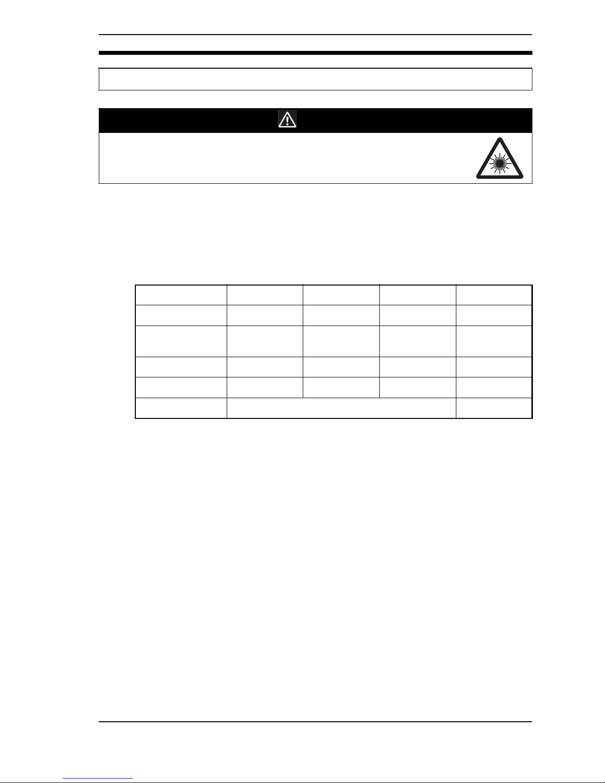
b WARNING
The laser radiation has a high power density and exposure may result in loss of sight.
Do not to expose your eyes to the laser radiation either directly or indirectly (i.e., after
reflection from a mirror or shiny surface).
Z300-S2T Z300-S5T Z300-S10 Z300-S60
Wave length 650 nm 670 nm 670 nm 658 nm
Maximum pulse
duration
7 ms 7 ms 7 ms 17.5 ms
Cycle 0.5 to 10 ms 0.5 to 10 ms 0.5 to 10 ms 0.5 to 25 ms
Peak power 1 mW max. 1 mW max. 1 mW max. 15 mW max.
Class 23B
PRECAUTIONS
Page 13
12
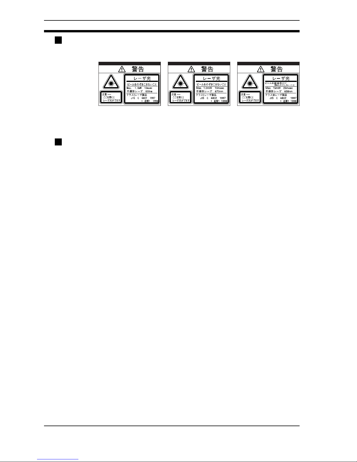
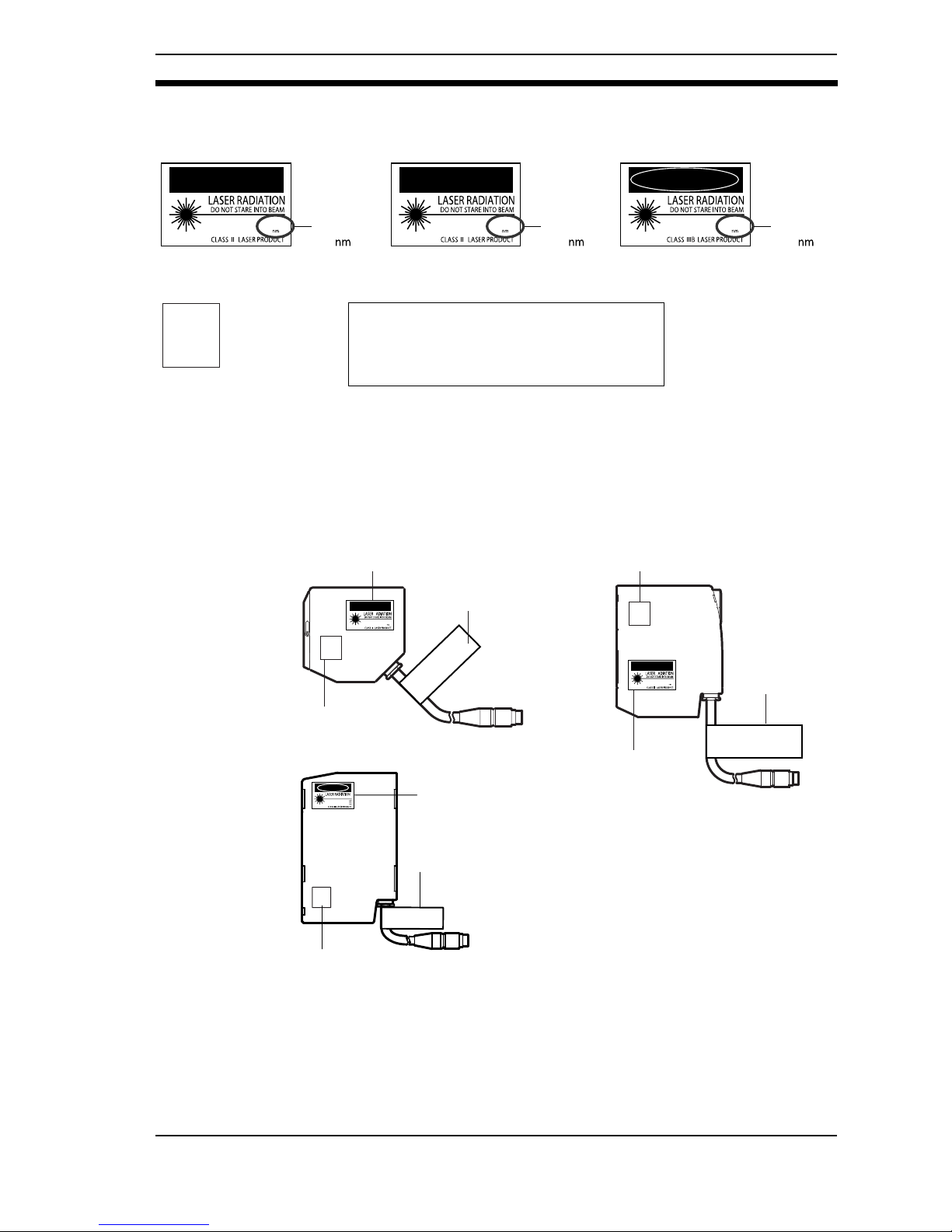
Labeling on Laser Use
The Sensor has the following WARNING label on the side.
Re-labeling
The following labels are provided, to be used selectively according to countries.
for use in the U.S.: FDA label (Aperture label, Caution logo label, Certification and
Identification label)
for use in countries other than the U.S.: Warning label according to EN/IEC standards.
Be sure to turn off the sensor before replacing the label, or your hand or other body parts may
be exposed to the hazardous laser beam radiating from the sensor.
§ Use in the U.S.
When a laser product mounted on a certain device is to be used in the U.S., it has to meet the
requirements set forth by the FDA (regulations for laser products set forth by the Food and
Drug Administration).
Applications have been approved by CDRH (Center for Devices and Radiological Health) for
Z300-S2T, Z300-S5T, Z300-S10, Z300-S60. Three different FDA labels are enclosed in the
sensor package. Attach them to the sensor body.
The Z300 is designed to be built into the finished system unit. Refer to the following technical
standard for installation.
21CFR1040.10 and 1040.11
Z300-S2T
Z300-S5T
Z300-S10
Z300-S60
PRECAUTIONS
Page 14
13
FDA Labels for Laser Products
Be sure to attach FDA labels; do not attach English WARNING labels by mistake.
Areas to Attach Labels
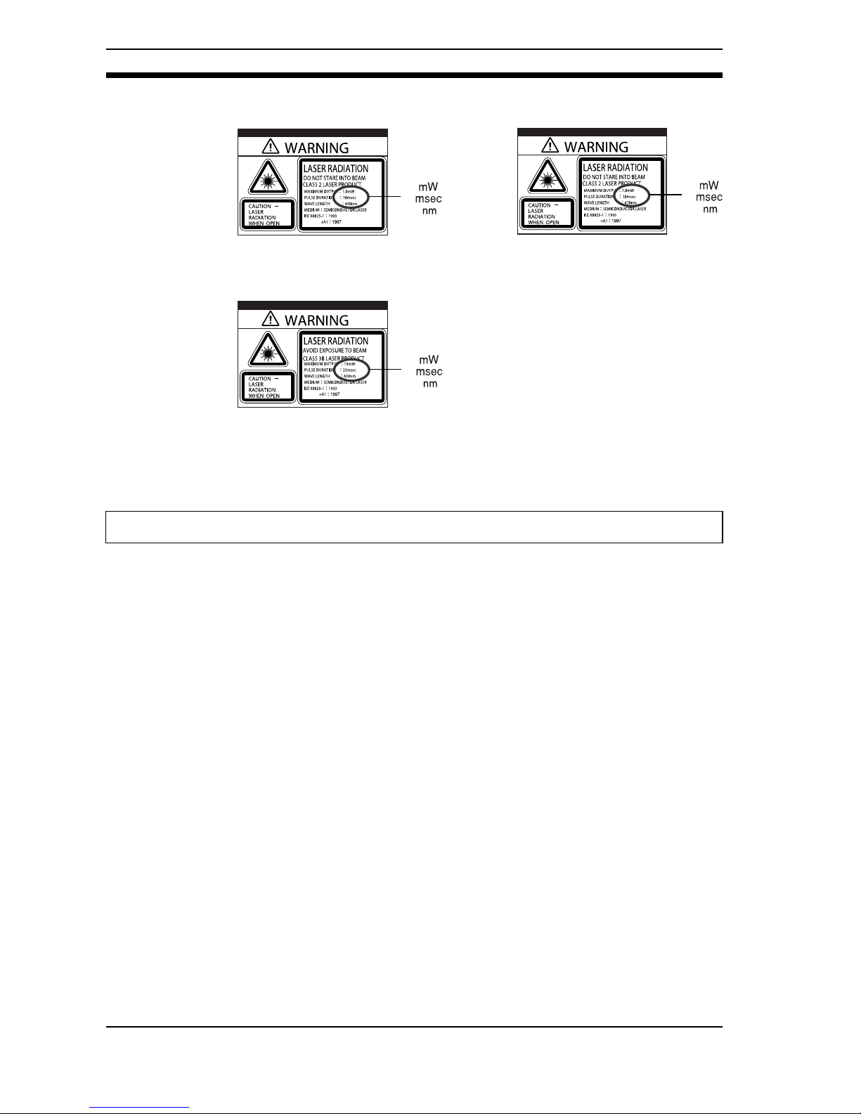
§ Use in Countries Other than the U.S.
Replace the warning label in Japanese on the sensor main body with the attached EN/IEC
warning label upon use in countries other than the U.S. Attach the label in the area where the
original Japanese warning label was provided.
EN60825-1(IEC60825-1) standard is applied to products exported to European countries.
The Z300 conforms to the standard.
CAUTION
PEAKPOWER
PULSEDURATION
WAVELENGTH
1000
10000
670
µw
µs
ClassIICautionlogotype ClassIICautionlogotype
ApertureLabel CertificationandIdentificationLabel
AVOID
EXPOSURE
Thislaserproductcomplieswith
21CFR1040.10and1040.11.
ShiokojiHorikawa,Shimogyo-ku,
Kyoto600-8530JAPAN
OMRONCorporation
AYABEFactory,OMRONCorp.
Placeofmanufacture:
Manufacturedin
Laserradiation
isemittedfrom
thisaperture
Z300-S5T/S10
CAUTION
PEAKPOWER
PULSEDURATION
WAVELENGTH
1000
10000
650
µw
µs
1000
10000
650
µw
µs
Z300-S2T
1000
10000
670
µw
µs
ClassIIIBDangerlogotype
Z300-S60
DANGER
DANGER
PEAK POWER
PULSE DURATION
WAVE LENGTH
15000
25000
658
µw
µs
15000
25000
658
µw
µs
CAUTION
PEAKPOWER
PULSEDURATION
WAVELENGTH
1000
10000
650
µw
µs
CAUTION
PEAKPOWER
PULSEDURATION
WAVELENGTH
1000
10000
670
µw
µs
AVOID
EXPOSURE
Laserradiation
isemittedfrom
thisaperture
AVOID
EXPOSURE
Laserradiation
isemittedfrom
thisaperture
Thislaserproductcomplieswith
21CFR1040.10and1040.11.
ShiokojiHorikawa,Shimogyo-ku,
Kyoto600-8530JAPAN
OMRONCorporation
AYABEFactory,OMRONCorp.
Placeofmanufacture:
Manufacturedin
ClassII
Cautionlogotype
ClassII
Cautionlogotype
ApertureLabel
ApertureLabel
Certificationand
IdentificationLabel
Certificationand
IdentificationLabel
Thislaserproductcomplieswith
21CFR1040.10and1040.11.
ShiokojiHorikawa,Shimogyo-ku,
Kyoto600-8530JAPAN
OMRONCorporation
AYABEFactory,OMRONCorp.
Placeofmanufacture:
Manufacturedin
Z300-S2T
Z300-S60
Z300-S5T/S10
AVOID
EXPOSURE
L
a
se
r ra
d
ia
tio
n
is e
m
itte
d
fro
m
th
is a
p
e
rture
T
h
i
s
l
a
s
e
r
p
r
o
d
u
c
t
c
o
m
p
l
i
e
s
w
i
t
h
2
1
C
F
R
1
0
4
0
.
1
0
a
n
d
1
0
4
0
.
1
1
.
S
h
io
k
o
ji H
o
rik
a
w
a
, S
h
im
o
g
y
o
-k
u
,
K
y
o
to
6
0
0
-8
5
3
0
J
A
P
A
N
O
M
R
O
N
C
o
r
p
o
r
a
t
i
o
n
A
Y
A
B
E
F
a
c
to
ry
, O
M
R
O
N
C
o
rp
.
P
l
a
c
e
o
f
m
a
n
u
f
a
c
t
u
r
e
:
M
a
n
u
f
a
c
t
u
r
e
d
i
n
DANGER
DANGER
PEAK POWER
PULSE DURATION
WAVE LENGTH
15000
25000
658
AVOID DIRECT EXPOSURE TO BEAM
ClassIIIB
Dangerlogotype
Certificationand
IdentificationLabel
ApertureLabel
PRECAUTIONS
Page 15
14
Warning Labels
Be sure to attach correct warning labels; do not attach FDA labels by mistake.
The Z300 conforms to the following EC directives and EN standards.
1. EC Directives
EMC Directive: No.89//336/EEC
2. EN Standards
EN61326: 1997+A1:1998+A2:2001(EMI:Class A)
Regulations and standards
1.0
10
670
Z300-S5T
Z300-S10
1.0
10
650
Z300-S2T
15
25
658
Z300-S60
PRECAUTIONS
Page 16

15
Please observe the following precautions for safe use of the product.
(1) Do not use the Z300 in environment with flammable or explosive gases.
(2) Install the Z300 away from high-voltage devices and moving machinery to
allow safe access during operation and maintenance.
(3) Use the Z300 with the power supply voltages specified in this manual.
(4) Use crimp terminals for wiring. Do not connect the power supply wires by just
twisting stranded wire and connecting directly to the terminals.
(5) Use the wire and crimp terminals of the proper sizes as specified in this man-
ual.
(6) Confirm that wiring has been performed correctly before turning ON the
power supply.
(7) Cover the terminal blocks with the Terminal Block Protection Covers.
Uncovered terminal blocks can result in electric shock.
(8) Use a DC power supply with countermeasures against high-voltage spikes
(safe extra low-voltage circuits on the secondary side).
(9) Be sure to securely tighten the screws when mounting the Z300.
(10)Do not attempt to dismantle, repair, or modify the Z300.
(11)Dispose of the Z300 as industrial waste.
Precautions for Safe Use
PRECAUTIONS
Page 17
16
Please observe the following precautions to prevent failure to operate, malfunctions, or undesirable
effects on product performance.
Components
The Sensor and Console connected to the Z300-VC10V4 Controller must be
products designed specifically for the Z300.
- Sensor (Z300-S2T, Z300-S5T, Z300-S10, Z300-S60)
- Console (Z300-KP)
Installation Site
Do not install the Z300 in locations subjected to the following conditions:
- Ambient temperature outside of 0 to +40°C for the F300-M09 Video Monitor
(recommended monitor) or outside of 0 to +50°C for other Z300 components.
- Condensation due to rapid temperature fluctuations
- Relative humidities outside 35 to 85%
- Corrosive or flammable gases
- Dust, salt, or iron particles
- Direct vibration or shock
- Reflection of intense light (such as other laser beams or electric arc-welding machine)
- Strong magnetic fields
- Direct sunlight
- Water, oil, or chemical fumes or spray
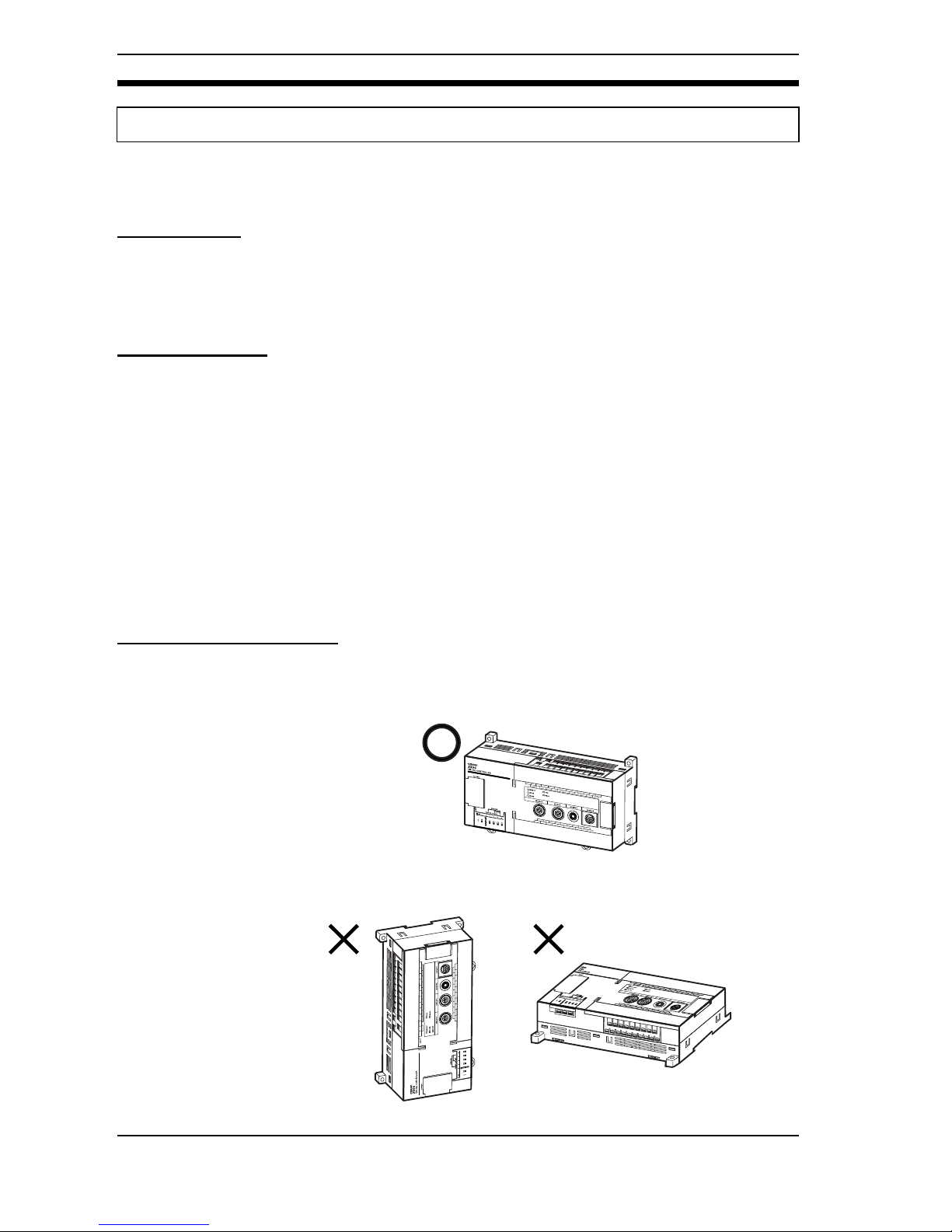
Installation Orientation
Orientation of Controller
To improve heat dissipation, install the Controller in the following direction only:
CORRECT
Do not install the Controller in the orientations shown in the following diagram.
INCORRECT
Precautions for Correct Use
PRECAUTIONS
Page 18
17
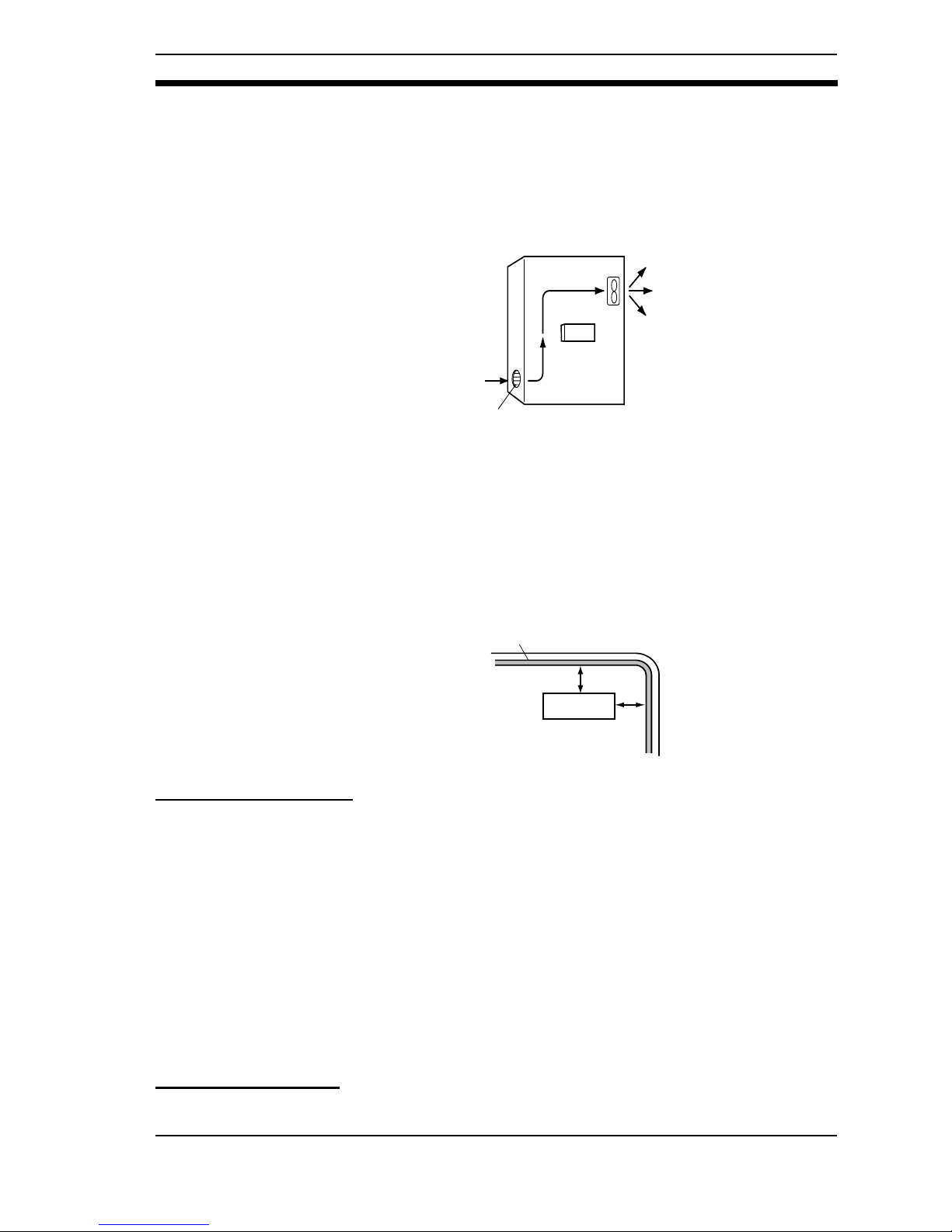
Ambient Temperature
- Maintain a minimum clearance of 50 mm above and below the Z300 to
improve air circulation.
- Do not install the Z300 immediately above significant heat sources, such as
heaters, transformers, or large-capacity resistors.
- Do not let the ambient temperature exceed 50°C.
- Provide a forced-air fan cooling or air conditioning if the ambient temperature is near 50°C so that the ambient temperature never exceed 50°C.
Ambient Illumination
Although the Z300 is rated for use in environments where the ambient illumination does not exceed 3000lx, if possible, do not use the Z300 near lighting equipment that turns ON and OFF continuously. If this is unavoidable, reduce the
influence of the light by, for example, using a light baffle.
Noise Resistance
- Do not install the Z300 in a cabinet containing high-voltage equipment.
- Do not install the Z300 within 200 mm of power cables.
Sensor Maintenance
- Install the Sensor in a clean environment and keep the filter on the front panel
of the Sensor free from oil and dust. If affected by oil or dust, clean the filter as
follows:
1. Use a blower brush (used to clean camera lenses) to blow large dust particles from the surface. Do not blow the dust away with your mouth.
2. Use a soft cloth (for lenses) with a small amount of alcohol to remove the
remaining dust. Do not use a scrubbing action when cleaning as scratches
on the filter could result in the Sensor malfunctioning.
Environment
The Sensor cannot accurately detect the following types of objects:
- Objects with an extremely low reflection ratio
- Objects with a small curvature
- Largely inclined objects
Connecting Cables
Always turn OFF the Z300's power before connecting or disconnecting cable.
Control panel
Z300
Louver
Z300
200 mm min.
200 mm min.
Power cable
PRECAUTIONS
Page 19
18
Touching Signal Lines in Connectors or Terminals
To prevent damage from static electricity, use a wrist strap or another device for
preventing electrostatic discharges when touching terminals or signal lines in
connectors.
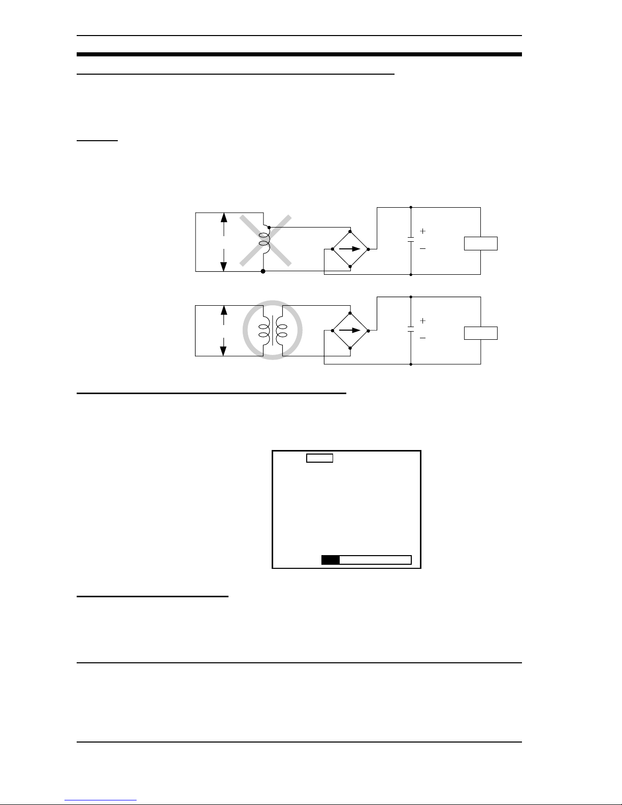
Wiring
When using a transformer for the Z300's driving power supply, use an isolation
transformer in the way shown below. Do not use an auto-transformer. Doing so
may result in equipment failure.
Turning OFF the Power (Visual Mode Only)
Do not turn OFF the power while a message is being displayed indicating that
processing is being performed. Data in memory will be destroyed, and the Z300
may not operate correctly the next time it is started.
Using the RESET Signal
Do not use the RESET input immediately after power is turned ON. When using
the RESET input to synchronize startup timing, wait at least 1 second after the
Z300's power supply is turned ON before turning ON the RESET terminal.
Securing the Video Monitor (When Using the Recommended F150-M09)
Observe the following precautions to prevent noise interference, because the
video monitor case is connected to the 0 V line in the internal circuits.
1. Do not ground the video monitor.
2. Do not ground the metallic part of the connector.
3. Secure the video monitor with plastic screws if it is being mounted to a metallic surface.
Z300
Z300
Auto-transformer
Isolation transformer
Commercial
power supply
Commercial
power supply
Scn 0▼
SAVE▼
Saving data.
PRECAUTIONS
Page 20

19
Warming Up
After turning ON the power supply, allow the Z300 to stand for at least 30 minutes before use. The circuits are unstable immediately after the power supply is
turned ON and attempting measurement may result in inconsistent measurement values.
Check the contents of the package as soon as you receive the Z300. It is extremely rare for components to be missing, but contact the nearest OMRON representative if any of the following items are
missing.
1. Z300-VC10EV3 Controller Qty: 1
2. SETUP MANUAL (This Manual) Qty: 1
3. OPERATION MANUAL Qty: 1
Some of the products listed may not be available in some countries. Please contact your nearest
OMRON sales office by referring to the addresses provided at the back of this manual.
The following headings appear in the left column of the manual to help you locate different types of
information.
Note Indicates information of particular interest for efficient and convenient operation
of the product.
Notice Indicates information required to take full advantage of the functions and perfor-
mance of the product. Incorrect application methods may result in the loss of
damage or damage to the product. Read and follow all precautionary information.
CHECK Indicates points that are important in using product functions or in application
procedures.
1,2,3... Indicates lists of one sort or another, such as procedures, checklists, etc.
SeeAlso Indicates where to find related information.
Screen Messages In this manual, screen message are given in bold/italic.
E.g.: Application
Confirming Package Contents
Product Availability
Visual Aids
Notation
PRECAUTIONS
Page 21

20
Page 22

21
SECTION 1
Features
This section introduces the features of the Z300.
1-1 Monitoring While Viewing the Measurement Status . . . . . . . . . . . . . . . . . . . . . . . . . . . 22
1-2 Simple Setup Using Menus! . . . . . . . . . . . . . . . . . . . . . . . . . . . . . . . . . . . . . . . . . . . . . . 23
1-3 A Wide Variety of Useful Functions. . . . . . . . . . . . . . . . . . . . . . . . . . . . . . . . . . . . . . . . 24
Page 23
22
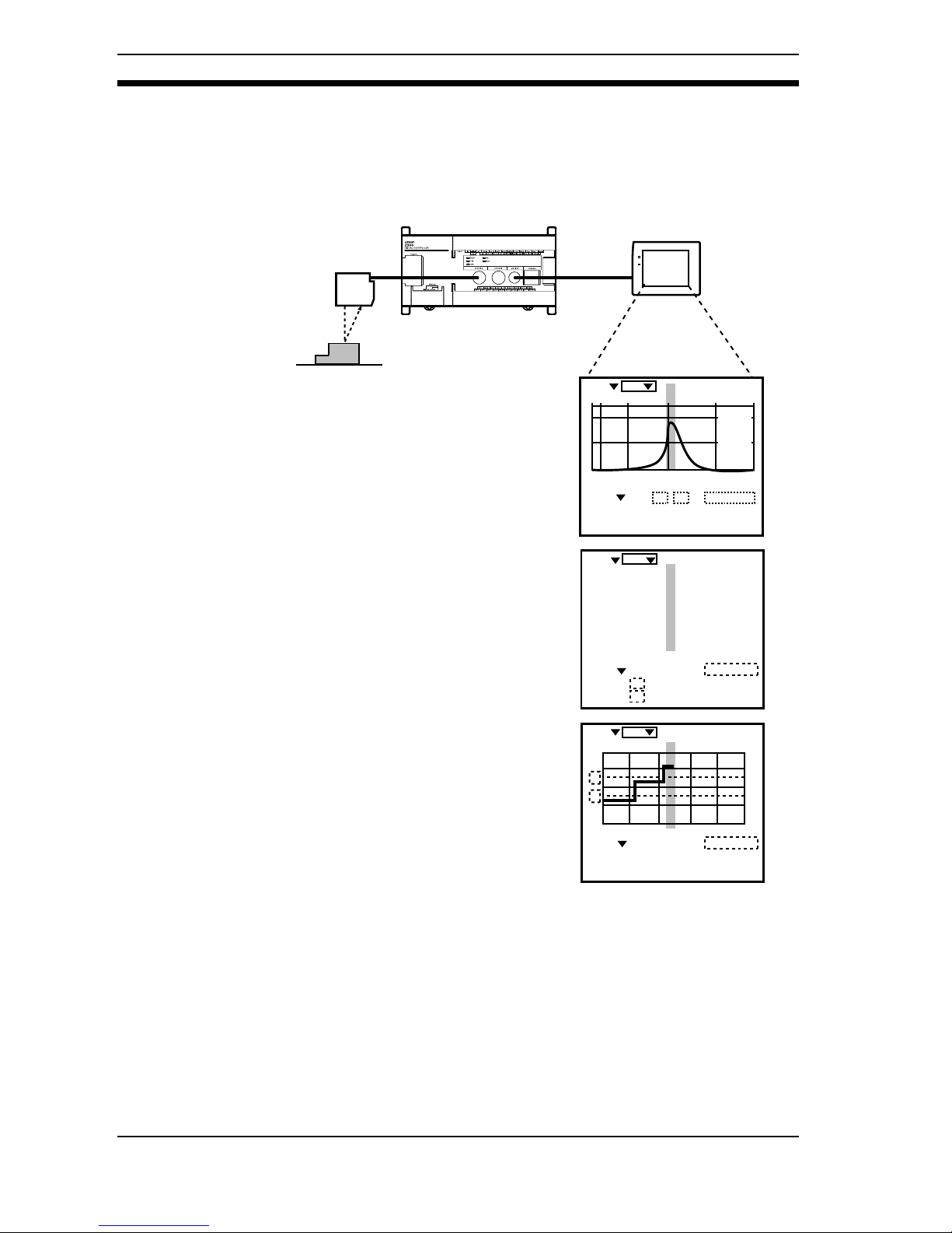
1-1 Monitoring While Viewing the Measurement Status
Monitoring suited to the application is possible at every stage from installation
and adjustment to operation and maintenance.
For details on the display, refer to page 12 in the Operation Manual.
Monitor
Sensor
Z300
POWER
SYNC
+
+001.6070 mm
PASS
HI LO ZERO OFF
SCN0 0.48ms
OUT 0
RUN
BRIGHT
DARK
NEAR
+
Sensor
0
LV [ 12]
PEAK[199]
Sensor
1
LV [---]
PEAK[---]
+001.6070
mm
PASS
HI=+005.0000 mm
LO=-005.0000 mm
RO OFF
SCN0 0.48ms
OUT 0
RUN
+
+001.6070 mm PASS
H
L
thru
ZERO OFF
SCN0 0.48ms
OUT 0
RUN
The status of laser beam images can be
displayed on the monitor screen.
It is possible to make fine adjustments to
the measurement position and to confirm
that the light density is not excessive or
insufficient.
Linear sensor controller-style digital display
is also possible.
Waveforms with measurement values ar-
ranged in chronological order can be dis-
played and so the shapes of the workpieces
moving along the line can be checked.
Monitoring While Viewing the Measurement Status Section 1-1
Page 24

23
1-2 Simple Setup Using Menus!
Set the measurement conditions on the Console according to the menus displayed on the monitor screen. The Z300 has 2 types of menu.
First, try out the Application Menu.
Measurement conditions for a representative application are already set and so
setting can be performed simply by selecting the measurement items.
Refer to page 28 in the Operation Manual.
Use the Expert Menu to set different measurement conditions from the preset
ones, or to add more detailed settings to the Application Menu settings.
Refer to page 43 in the Operation Manual.
Application
Sf displace
Spot displace
Max. height
Groove/dent
Step
Transp thick
Step(2sensor)
Thik(2sensor)
Select the application
ENT:Next ESC:Back
Select from these items.
The Z300 is factory-set to
perform surface displacement measurement when
the power supply is turned
ON.
Scn0
SET
Point/Equation
Conditions
Hold
Avg/Filter
Details
Select the item
to be set.
Simple Setup Using Menus! Section 1-2
Page 25
24
1-3 A Wide Variety of Useful Functions
Useful Feature for Sensor Installation!
The Sensor's installation conditions and orientation can be adjusted while monitoring the CCD's received light density.
Refer to page 118 in the Operation Manual.
Useful for Analyzing the Causes of NG Images!
Laser beam images and waveforms for NG images can be recorded. Recorded
images can be reproduced to help analyze the cause of NG images.
Refer to page 122 in the Operation Manual.
Easy Settings for Measuring Workpiece Thickness and Level Differences!
Two Sensors can be connected to the Controller, allowing measurement conditions to be set easily.
(Connect the same models of Sensor.)
Refer to page 29 in the Operation Manual.
A Variety of Output Formats!
Not only is analog output available, but communications with external devices
can also be performed via terminal blocks or RS-232C.
For details on terminal block output, refer to page 150 in the Operation
Manual.
For details on RS-232C output, refer to page 157 in the Operation Manual.
For details on analog output, refer to page 173 in the Operation Manual.
Comprehensive Hold Functions!
Hold Mode can be set freely at up to 4 points (times).
Refer to page 65 in the Operation Manual.
A Wide Variety of Useful Functions Section 1-3
Page 26

25
SECTION 2
Wiring and Connection
Procedures for wiring power supplies and ground wires and for connecting to external devices are described in
this section.
2-1 Component Names and Functions. . . . . . . . . . . . . . . . . . . . . . . . . . . . . . . . . . . . . . . . . . 26
2-2 System Configuration . . . . . . . . . . . . . . . . . . . . . . . . . . . . . . . . . . . . . . . . . . . . . . . . . . . 30
2-3 Connecting Peripheral Devices . . . . . . . . . . . . . . . . . . . . . . . . . . . . . . . . . . . . . . . . . . . . 33
2-4 Power Supply and Ground . . . . . . . . . . . . . . . . . . . . . . . . . . . . . . . . . . . . . . . . . . . . . . . 35
2-5 Terminal Block Connections. . . . . . . . . . . . . . . . . . . . . . . . . . . . . . . . . . . . . . . . . . . . . . 37
2-6 RS-232C Connections . . . . . . . . . . . . . . . . . . . . . . . . . . . . . . . . . . . . . . . . . . . . . . . . . . . 41
2-7 Linear Sensor Controller Connections . . . . . . . . . . . . . . . . . . . . . . . . . . . . . . . . . . . . . . 43
Page 27

26
2-1 Component Names and Functions
Sensor
Receiver
Emitter
NEAR indicator
Z300-S5T Sensor
Z300-S10 Sensor
FAR indicator
Emitter
Receiver
Z300-S60 Sensor
NEAR indicator
FAR indicator
Emitter
Receiver
Z300-S2T Sensor
NEAR indicator
Monitor
FAR indicator
Light
Beam cover
Component Names and Functions Section 2-1
Page 28
27
, If the distance between the front of the Sensor and the workpiece is the
measurement range, these indicators turn ON or OFF according to the distance.
If the workpiece is outside the measurement range or if the light density is insuf-
ficient, both indicators will flash.
These indicators also act as laser beam warning indicators.
- Immediately after the power supply is turned ON, one or both of these indicators will light or flash.
- For 15 to 25 seconds after the power supply is turned ON, both indicators will
be OFF indicating that the laser beam is OFF.
- When the laser beam turns ON, one of these indicators will light or flash.
- When the laser beam turns OFF, both indicators will turn OFF.
Emits laser beam.
Receives laser beam.
Light used when displaying surrounding images.
Captures surrounding images.
Used for switching between display of surrounding images and measurement. To display surrounding images, loosen the screws of the beam cover
lever and move the lever to the left. To perform measurement, move the lever to
the right. Tighten the lever screws with a flat-bladed screwdriver to a torque in
the range 0.15 to 0.3 N•m (1.5 to 3 kgf•cm).
CHECK When Using the Z300-S2T
- When performing measurement with the beam cover removed, attach the
monitor cap provided with the Sensor in the way shown below.
- When displaying surrounding images, be sure to attach the beam cover. Surrounding images cannot be displayed correctly without the beam cover
attached.
Distance to measurement center
Measurement range lower limit
Outside measurement range
NEAR indicator
FAR indicator
Lit
Flashing
Not lit
Z300-S2T
Z300-S10
Z300-S5T
Z300-S60
20
100
50
600
19.9
98
49.5
565
19
80
45
250
20.1
102
50.5
635
21
120
55
950
(Unit: mm)
Outside measurement range
Measurement range upper limit
Display of surrounding images
Lever
Measurement
Lever
Two, M2 × 4
Lever screws: M2 × 5
Monitor cap
(provided as an accessory)
Beam Cover Attached
Beam Cover Removed
Component Names and Functions Section 2-1
Page 29
28
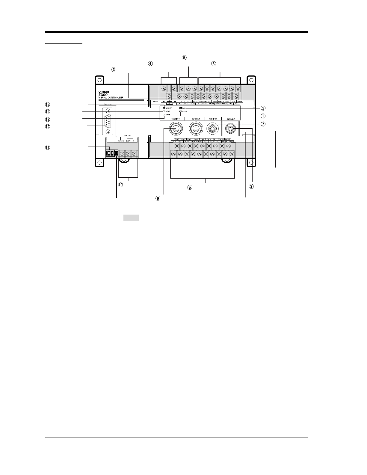
Controller
Monitor connector
RS-232C
connector
Sensor Connector
Output terminals
Analog
Output terminals
DIP Switch
Output
terminals
* Do not open.
*Do not remove
the sticker on the side.
* Do not use.
Console connector
NEAR indicator
FAR indicator
BRIGHT indicator
STAB indicator
DARK indicator
Shading indicates parts that are lifted to see the terminals underneath.
Ground terminal
Power Supply
terminals
Input
terminals
Component Names and Functions Section 2-1
Page 30
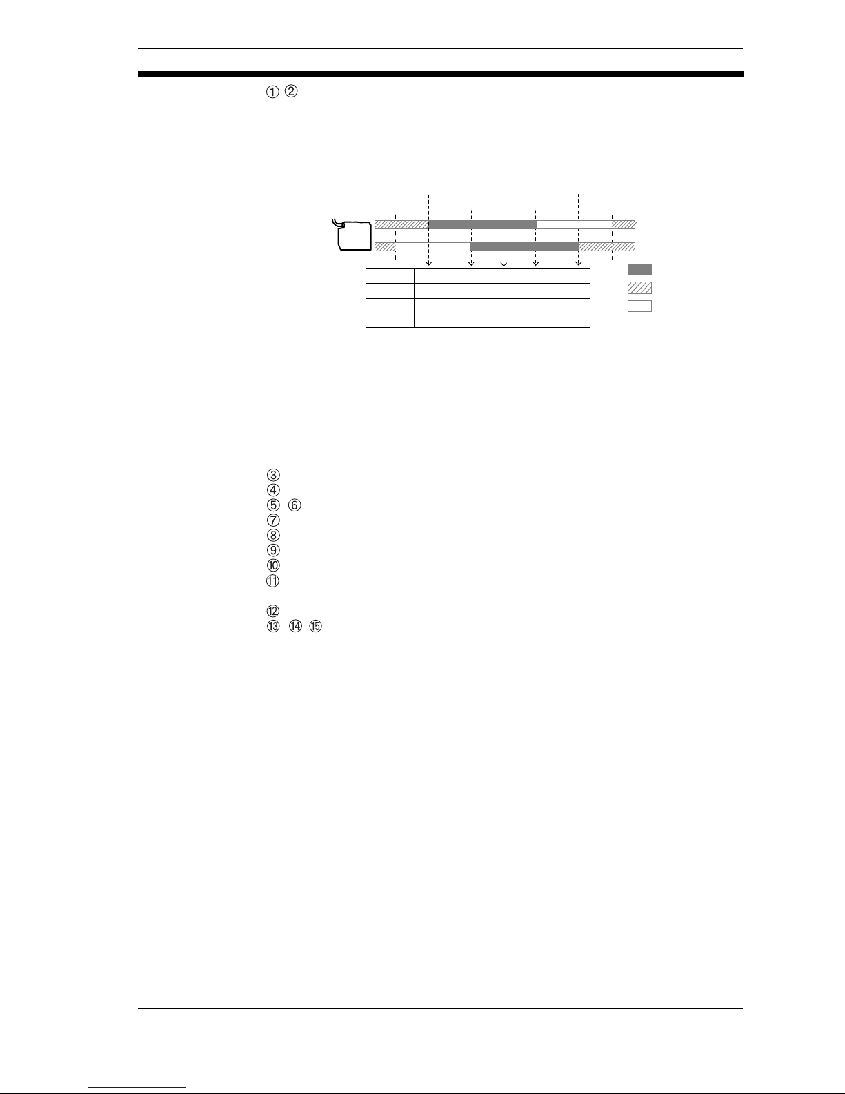
29
, If the distance between the front of the Sensor and the workpiece is the
measurement range, these indicators turn ON or OFF according to the distance.
If the workpiece is outside the measurement range or if the light density is insufficient, both indicators will flash.
These indicators also act as laser beam warning indicators.
- Immediately after the power supply is turned ON, one or both of these indicators will light or flash.
- For 15 to 25 seconds after the power supply is turned ON, both indicators will
be OFF indicating that the laser beam is OFF.
- When the laser beam turns ON, one of these indicators will light or flash.
- When the laser beam turns OFF, both indicators will turn OFF.
Connects to the ground wire.
Connects to the power supply.
, Connects to external devices such as a PLC.
Connects to the monitor.
Connects to a console.
Connects to the sensor.
Connected when using analog output.
Set when using the Z300 in Non-visual Mode.
Refer to page 55.
Connects to external devices such as a personal computer or PLC.
,,
Turn ON according to the light density at the Sensor.
If LDOFF is input via the terminal block or RS-232C, or if the Sensor is not connected, all of the indicators flash.
- BRIGHT indicator···Turns ON when the light density is too high.
- DARK indicator ···Turns ON when the light density is insufficient.
- STAB indicator ···Turns ON when the light density is suitable.
Distance to measurement center
Measurement range lower limit
Outside measurement range
NEAR indicator
FAR indicator
Lit
Flashing
Not lit
Z300-S2T
Z300-S10
Z300-S5T
Z300-S60
20
100
50
600
19.9
98
49.5
565
19
80
45
250
20.1
102
50.5
635
21
120
55
950
(Unit: mm)
Outside measurement range
Measurement range upper limit
Component Names and Functions Section 2-1
Page 31

30
2-2 System Configuration
2-2-1 System Configuration for Visual Mode
The Z300 is provided with menus that allow easy setting of measurement conditions to suit the application. Perform settings on the Console using the menu
items displayed on the monitor. Waveform measurement results can also be displayed on the monitor.
The mode used for this type of operation is called "Visual Mode." If the DIP
switch on the Controller is set to VISUAL, the Z300 goes into Visual Mode when
the power supply is turned ON. The DIP switch is factory-set to VISUAL.
CHECK - Up to 2 Sensors can be connected.
When performing measurement with 2 Sensors at the same time, use Sensors of the same model. It is possible to connect different Sensors but it will
not be possible to perform measurement using both at the same time.
For details on using different models, refer to page 146 in the Operation
Manual.
Power Supply
Recommended model: OMRON
S82K-05024(See page 36)
∗
Sensor (See page 50)
Z300-S2T (2-m cable)
Z300-S5T (2-m cable)
Z300-S10 (2-m cable)
Z300-S60 (0.5-m cable)
∗
Sensor Extension Cable
Z309-SC1R (1.5m, 3 m, 8 m, 13 m, or 18 m)
Specify the required cable length
when ordering.
Z300-VC10EV3/Z300-VC15EV3 Controller
∗
Console
Z300-KP(2-m cable)
∗Components marked with
an asterisk are specially
designed for the Z300.
Other products cannot be used.
ESC TRIG
SHIFT
ENT
CONSOLE
System Configuration Section 2-2
Page 32

31
CHECK When Using the Z300-S60
- When using the Extension Cable, set the length of the Extension Cable in
SYS/ Environment. This reduces errors due to the extended cable length.
For details, refer to page 140 in the Operation Manual
Notice Always turn OFF the power supply before connecting or disconnecting cables.
The peripheral device may be damaged if connected or disconnected with the
power supply turned ON.
Programmable Controller
Personal Computer
Linear Sensor Controller
K3TS
K3AS
K3TJ
K3NX
CQM1-LSE
See page 44
F150-VM Monitor Cable(2 m)
BNC Jack (provided with the F150-VM)
F150-M05L Liquid
Crystal Monitor
(pin input)
F300-M09 CRT
Video Monitor(BNC input)
POWER
SYNC
POWER
Expand the System to Suit the Application
8
9.012
0
12.345 67.891
System Configuration Section 2-2
Page 33

32
2-2-2 System Configuration for Non-visual Mode
The Z300 can be used without a monitor but with a Linear Sensor Controller
connected. In this case, the Z300's menus cannot be used. The way in which the
Z300's analog outputs are used is set at the Linear Sensor Controller.
The mode for this type of operation (without being able to see menus and waveforms) is called "Non-visual Mode." To perform operation in Non-visual Mode,
the DIP switch on the Controller must be set to NON VISUAL.
Refer to page 55.
Notice Turn OFF the power supply before changing the DIP switch settings.
CHECK When Using the Z300-S60
Use with a cable extension length of less than 3 m in Non-visual Mode.
CHECK Only 1 Sensor can be connected. Connect it to SENSOR 0.
Notice Always turn OFF the power supply before connecting or disconnecting cables.
The peripheral device may be damaged if connected or disconnected with the
power supply turned ON.
Power Supply
Recommended model:
OMRON S82K-05024
(See page 36)
Linear Sensor Controller (See page 44)
K3TS (Linear Sensor Digital Panel Meter)
K3AS (Linear Sensor Controller)
K3TJ (Scaling Mater)
K3NX (Digital Panel Meter)
CQM1-LSE (Linear Sensor Interface Unit)
∗
Sensor (See page 48)
Z300-S2T (2-m cable)
Z300-S5T (2-m cable)
Z300-S10 (2-m cable)
Z300-S60 (0.5-m cable)
∗
Sensor Extension Cable
Z309-SC1R
(1.5 m, 3 m, 8 m, 13 m, or 18 m)
Specify the required cable
length when ordering.
89.0
1
2
0
12.345
67.891
∗Components marked with
an asterisk are specially
designed for the Z300.
Other products cannot be used.
System Configuration Section 2-2
Page 34

33
2-3 Connecting Peripheral Devices
This section shows how to connect peripheral devices to the Controller.
Notice Always turn OFF the power supply before connecting or disconnecting a periph-
eral device's cable. The peripheral device may be damaged if it is connected
while the power is ON.
Notice The various connectors on the Controller are capped when the Controller is
shipped.
When a connector is not being used, leave the cap in place or replace the cap to
protect against dust, dirt, and static electricity.
Connecting a Console
Connect the console Z300-KP to the Controller's console connector.
Connecting a Monitor
Connect the monitor cable F150-VM to the Controller's monitor connector.
ESC TRIG
SHIFT
ENT
CONSOLE
CONSOLE
POWER
SYNC
MONITOR
Connecting Peripheral Devices Section 2-3
Page 35
34
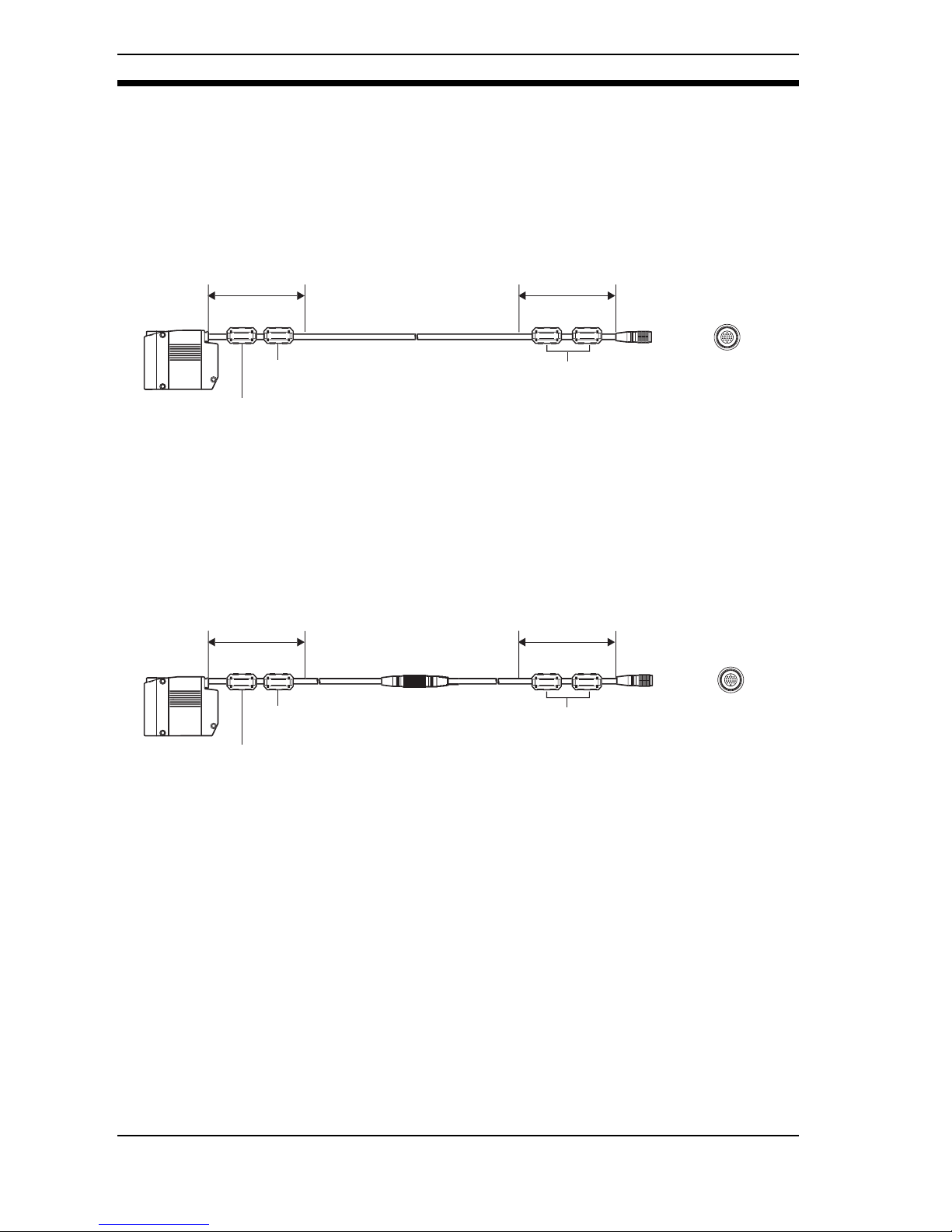
Connecting a Sensor
Connect the sensor to the Controller's sensor connector. Three ferrite cores
(supplied with the sensor) must be attached to the sensor cable. Two ferrite
cores can be connected within 100 mm from the sensor and within 100 mm from
the controller's connector, respectively.
When using an extension cable, make sure that two ferrite cores are connected
within 100 mm from the sensor and within 100 mm from the controller's connector, respectively.
SENSOR
Within 100 mm
Ferrite core
(Ferrite cores have already been
installed on the sensor. However,
their positions can be changed if
necessary.)
Ferrite core (standard accessory)
Within 100 mm
Ferrite core (standard accessory)
SENSOR
Within 100 mm
Ferrite core
(Ferrite cores have already been
installed on the sensor. However,
their positions can be changed if
necessary.)
Ferrite core (standard accessory)
Ferrite core (standard accessory)
Within 100 mm
Connecting Peripheral Devices Section 2-3
Page 36

35
2-4 Power Supply and Ground
Wire the power supply and the ground to their respective terminals.
2-4-1 Crimp Terminals and Cables
The terminal block uses M3 terminal screws. Use appropriate crimp terminals
for M3 screws as shown below. Tighten the screws to a torque of between 0.5
and 0.6 N•m. After wiring, confirm that the wiring is correct.
Notice Cover the terminal blocks with the Terminal Block Protection Covers. Uncov-
ered terminal blocks can result in electric shock.
2-4-2 Ground Wiring
Notice -Be sure to ground to 100Ω or less.
-Always connect a ground wire to the Z300's ground terminal. To avoid
grounding problems, do not share the ground wire with any other devices or
wire the ground to the building's steel framing.
-Use a grounding point that is as close as possible and keep the ground wiring
as short as possible.
Recommended Crimp Terminals
Manufacturer Model Recommended wire size
Forked J.S.T. Mfg Co.,Ltd V1.25-N3A
1.31 to 1.65mm
2
Round J.S.T. Mfg Co.,Ltd V1.25-MS3
6.2 mm max.
6.2 mm max.
Forked Round
Ground to
100Ω or less.
Power Supply and Ground Section 2-4
Page 37

36
2-4-3 Wiring the Power Supply
Use a power supply that meets the following specifications.
CHECK Use a DC power supply with countermeasures against high-voltage spikes (safe
extra low-voltage circuits on the secondary side).Excessively high voltages can
result in electric shock.
Notice - Wire the Power Supply Unit independently of other devices. In particular,
keep the power supply wired separately from inductive loads.
- Keep the power supply wiring as short as possible. (10 m max.)
- If UL recognition is required, use a UL class II power supply.
Recommended Power Supply: OMRON S82K-05024
Output current 1.6 A min.
Power supply voltage 24 VDC (21.6 to 26.4VDC)
+
-
24VDC
Power Supply and Ground Section 2-4
Page 38

37
2-5 Terminal Block Connections
2-5-1 Crimp Terminals and Cables
The terminal block uses M3 terminal screws. Use appropriate crimp terminals
for M3 screws as shown below. Tighten the screws to a torque of between 0.5
and 0.6 N•m.
Notice Cover the terminal blocks with the Terminal Block Protection Covers. Uncov-
ered terminal blocks can result in electric shock.
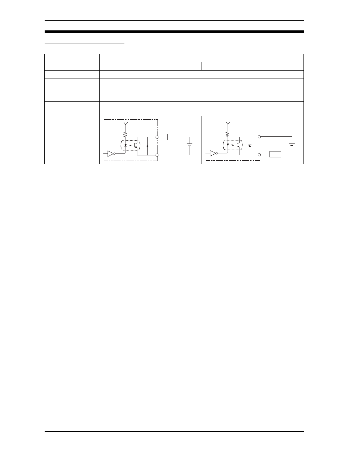
2-5-2 Internal Specifications
CHECK Use a DC power supply with countermeasures against high-voltage spikes (safe
extra low-voltage circuits on the secondary side). Excessively high voltages can
result in electric shock.
Input Specifications
Recommended Crimp Terminals
Manufacturer Model Recommended wire size
Forked J.S.T. Mfg Co.,Ltd V1.25-N3A
1.31 to 1.65mm
2
Round J.S.T. Mfg Co.,Ltd V1.25-MS3
Item Specification
Model Z300-VC10EV3 (NPN mode) Z300-VC15EV3 (PNP mode)
Input voltage 12 to 24 VDC ±10%
ON current *1 5 to 15 mA
ON voltage *1 8.8 V max.
OFF current *2 0.1 mA max.
OFF voltage *2 4.5 V min.
ON delay
RESET input:10 ms max.
Other inputs: 0.5 ms max
OFF delay
RESET input:15 ms max.
Other inputs: 0.7 ms max.
Internal circuits
6.2 mm max.
6.2 mm max.
Forked Round
COM IN
+
Input
terminal
COM IN
+
Input
terminal
Terminal Block Connections Section 2-5
Page 39
38
Output Specifications
Notice Do not exceed the maximum load current specified for the Controller.
*1 ON Current/ON Voltage
This refers to the current or voltage values needed to shift from the OFF→ON
state.
The ON voltage value is the potential difference between each of the input terminals and COM IN.
*2 OFF Current/OFF Voltage
This refers to the current or voltage values needed to shift from the ON→OFF
state.
The OFF voltage value is the potential difference between each of the input terminals and COM IN.
Item Specification
Model Z300-VC10EV3 (NPN mode) Z300-VC15EV3 (PNP mode)
Output voltage 12 to 24 VDC ±10%
Load current 45 mA max.
ON residual volt-
age
2 V max.
OFF leakage current
0.1 mA max.
Internal circuits
COM OUT
Output terminal
+
Load
COM OUT
Output terminal
+
Load
Terminal Block Connections Section 2-5
Page 40

39
2-5-3 Terminal Names
CHECK There are 3 types of COM OUT (*1 to *3) for each output terminal. Connect with
reference to the table at right.
DO 16
24VDC
ZERO 0
+
-
DO 18
DO 17
DO 19
RESET
TRIGGER
DI 1
ZERO 1
DI 3
NCNC
DI 2
GATE
DI 0
DO 1
DO 3
DO 5
DO 7
NC
DO9
DO 11
DO 13
DO 15
DO 8
DO 10
DO 12
DO 14
DO 0
DO 4 DO 6
DO 2
(∗1)
(∗2) (∗3)
ALL-
ZERO
HOLD-
RST
LDOFF
Output terminals
Output terminals
Input terminals
Terminal Block Connections Section 2-5
Page 41

40
2-5-4 Terminal Applications
Output Terminals
Input Terminals
Notice - Do not reverse the connections of the signal terminals and COM terminals.
- Do not input the RESET input immediately after turning ON the power.
When using RESET input to synchronize startup timing, wait at least 1 s after
turning ON the Z300's power supply before turning ON the RESET terminal.
CHECK - The initial status of the output terminals is OFF. The terminals, however,
may turn ON for approximately 0.5 s when the power is turned ON. Be sure
to allow for this when connecting to an external device.
Name Application Name Application
DO 0
Measurement results output
DO 14
Measurement results output
DO 1 DO 15
DO 2 DO 16
DO 3 DO 17
DO 4 DO 18
DO 5 DO 19
DO 6
GATE
Control terminals
For details, refer to page
150 in the Operation Manual.
DO 7
DO 8
COM OUT
(*1)
Common for DO 16 to 19
and GATE
DO 9
DO 10
COM OUT
(*2)
Common for DO 0 to 7
DO 11
DO 12
COM
OUT(*3)
Common for DO 8 to 15
DO 13
Name Application
HOLD RST
Control terminals
For details, refer to page 150 in the Operation
Manual.
LD OFF
TRIGGER
ALL ZERO
ZERO 0
ZERO 1
DI 0
Command input
DI 1
DI 2
DI 3
RESET For resetting the Z300
COMIN Common for all input terminals
Terminal Block Connections Section 2-5
Page 42

41
2-6 RS-232C Connections
2-6-1 Connector
The Z300 uses 9-pin D-SUB female connectors. Use a compatible connector.
Recommended Plug and Hood
#
$
'
Model Manufacturer
Plug: XM2A-0901
OMRON Corp.
Hood: XM2S-0911
Pin No. Signal Name
1 FG(GND)
Protective frame
ground
2 SD(TXD) Send Data
3 RD(RXD) Receive Data
4 RS(RTS) Request to Send
5 CS(CTS) Clear to Send
6 NC Not connected
7 NC Not connected
8 NC Not connected
9 SG(GND) Signal ground
RS-232C Wiring Section 2-6
Page 43

42
2-6-2 Wiring
Only use a shielded RS-232C cable. The maximum cable length is 15 m.
Standard Wiring
Wiring for RS/CS Control
Note Pin numbers on the external device will depend on the device being connected.
Refer to the manual for the personal computer or PLC being connected.
2-6-3 Connection
Align the connector with the socket and press the connector straight into place.
Tighten the two screws on the edges of the connector.
Notice - Always turn OFF the power supply before connecting or disconnecting
cables. The peripheral device may be damaged if connected or disconnected with the power supply turned ON.
- Always tighten the connector screws.
Pin No.
Z300
Signal
SD(TXD)
RD(RXD)
RS(RTS)
CS(CTS)
SG(GND)
2
3
4
5
9
Pin No.
External device
Signal
SD(TXD)
RD(RXD)
RS(RTS)
CS(CTS)
SG(GND)
∗
∗
∗
∗
∗
Shield
Pin No.Signal
SD(TXD)
RD(RXD)
RS(RTS)
CS(CTS)
SG(GND)
2
3
4
5
9
Pin No.
External device
Signal
SD(TXD)
RD(RXD)
RS(RTS)
CS(CTS)
SG(GND)
∗
∗
∗
∗
∗
Shield
Z300
RS-232C Wiring Section 2-6
Page 44

43
2-7 Linear Sensor Controller Connections
2-7-1 Crimp Terminals and Cables
The terminal block uses M3 terminal screws. Use appropriate crimp terminals
for M3 screws as shown below. Tighten the screws to a torque of between 0.5
and 0.6 N•m.
Caution Cover the terminal blocks with the Terminal Block Protection Covers. Uncov-
ered terminal blocks can result in electric shock.
2-7-2 Terminal Names
CHECK Terminal 0 and the 4 to 20-mA terminal can be used for 1 to 5-V voltage output
by connecting the 250-Ω resistor provided.
Recommended Crimp Terminals
Manufacturer Model Recommended wire size
Forked J.S.T. Mfg Co.,Ltd V1.25-B3A
1.31 to 1.65mm
2
Round J.S.T. Mfg Co.,Ltd V1.25-MS3
Name Application
4 to 20mA Analog output terminal for current output in the range 4 to 20 mA.
-5 to 5V Analog output terminal for voltage output in the range -5 to 5 V.
0 Connected to input devices as a ground for analog output.
6.0 mm max.6.0 mm max.
Forked Round
Linear Sensor Controller Connections Section 2-7
Page 45

44
2-7-3 Internal Specifications
2-7-4 Connection Examples for the Linear Sensor Controller
Connecting to the Linear Sensor Digital Panel Meter (K3TS)
.
Linear Sensor Controller Connections Section 2-7
Page 46

45
Connecting to the Linear Sensor Controller (K3AS)
Connecting to the Scaling Meter (K3TJ)
K3TJ-A116R
Linear Sensor Controller Connections Section 2-7
Page 47

46
Connecting to the Digital Panel Meter (K3NX)
Connecting to the Linear Sensor Interface Unit (CQM1-LSE)
1
3
5
7
9
11
13
15
17
0
2
4
6
8
10
12
14
16
COM
+24V
DC
+24V
DC
4 to 20mA
24 VDC
CQM1-LSE01
ZERO
RES
T/O
ZRES
4to20mA
0V
-5to5V
Linear Sensor Controller Connections Section 2-7
Page 48

47
SECTION 3
Installation
This section provides installation methods for the Controller and Sensor.
3-1 Mounting the Controller . . . . . . . . . . . . . . . . . . . . . . . . . . . . . . . . . . . . . . . . . . . . . . . . . 48
3-2 Mounting the Sensor . . . . . . . . . . . . . . . . . . . . . . . . . . . . . . . . . . . . . . . . . . . . . . . . . . . . 50
Page 49

48
3-1 Mounting the Controller
There are two ways to mount the Controller: DIN Track mounting or surfacemounting.
3-1-1 DIN Track Mounting
The Controller can be easily mounted to or removed from 35-mm DIN Track.
Mounting the Controller
Hook the Controller into the DIN Track as shown in the diagram and then press
in at the bottom until the Controller locks into place.
Removing the Controller
Use a flat-bladed screwdriver to pull the hook down and then pull out the Controller from the bottom.
OMRON's PFP-M
End Plate
DIN Track
The following DIN Tracks are available
from OMRON.
PFP-100N (1 m)
PFP-50N (50 cm)
PFP-100N2 (1 m)
Hook
Mounting the Controller Section 3-1
Page 50
49
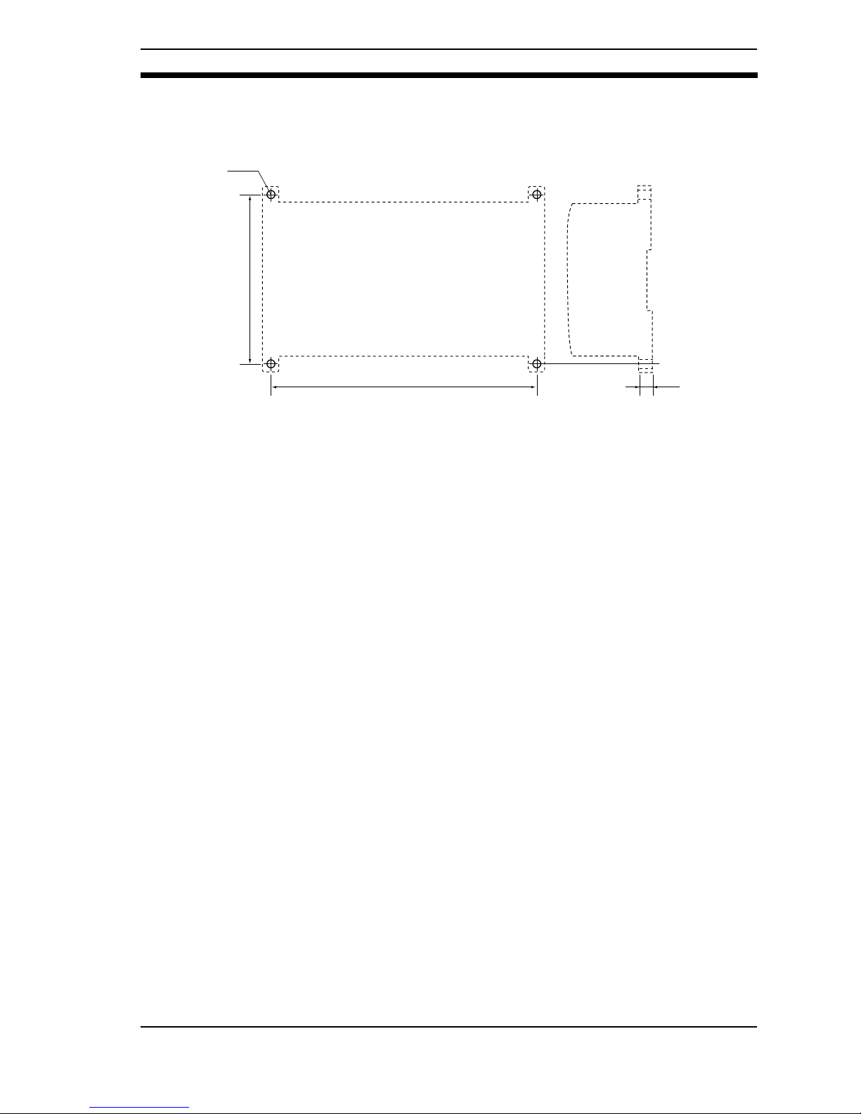
3-1-2 Surface Mounting
Use the holes and dimensions shown in the following diagram.
185±0.2
100±0.2
8
Four, M4
(Unit: mm)
Mounting the Controller Section 3-1
Page 51

50
3-2 Mounting the Sensor
Up to 2 Sensors can be connected per Controller. When using the Z300 in Nonvisual Mode, however, only 1 Sensor can be connected.
WARNING Do not to expose your eyes to the laser radiation either directly or indi-
rectly (i.e., after reflection from a mirror or shiny surface). The laser radiation has a high power density and exposure may result in loss of sight.
Notice Only sensors specifically for the Z300 can be used.
Using another type of sensor may result in damage to the sensor or controller.
3-2-1 Sensor Types
Reference
distance
(A)
Measure-
ment
range
(B)
Spot diameter
(C)
Line beam width
(D)
Super-precision
Model: Z300-S2T
20mm ±1mm
B=-1mm : 50µm
B=0mm : 20µm
B=+1mm : 50µm
0.3mm
(The width of the measurement
region is 0.2 mm)
High-precision
Model: Z300-S5T
50mm ±5mm
B=-5mm : 140µm
B=0mm : 30µm
B=+5mm : 140µm
0.4mm
Long-range Model:
Z300-S10
100mm ±20mm
B=-20mm : 280µm
B=0mm : 60µm
B=+20mm : 280µm
1.0mm
Super Long-range
Model: Z300-S60
600mm ±350mm
B=-350mm : 0.8mm
B=0mm : 0.4mm
B=+350mm : 1.3mm
B=-350mm : 10mm
(The width of the measurement
region is 5.0mm)
B=0mm : 18mm
(The width of the measurement
region is 12.4mm)
B=+350mm : 26mm
(The width of the measurement
region is 20mm)
Line beam
DC
A
B
Front View
Z300-S2T/S5T/S10
Line beam
D
Z300-S60
View in the direction of the arrows
Mounting the Sensor Section 3-2
Page 52
51
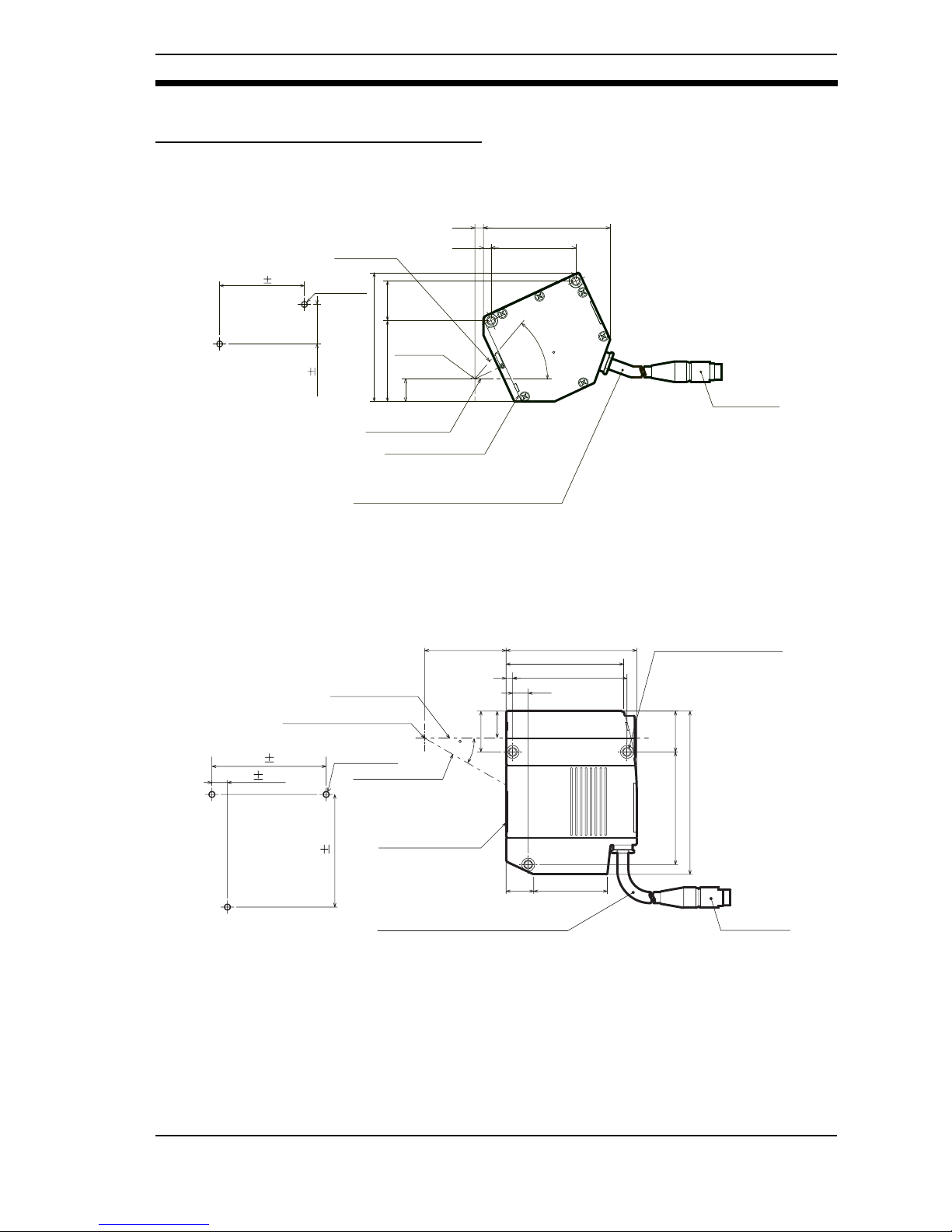
3-2-2 Mounting Dimensions
Dimensions for Diffuse Reflection
Super-precision Model: Z300-S2T
High-precision Model: Z300-S5T
Connector
Vinyl-insulated round cable 6.8 dia.
Standard length 2m
Emission axis
Reference plane
5.2 77.2
Two, M4
51.74.7
13.8
24.149.3
78.4
Mounting Hole
Cutout Dimensions
Reception
axis
50
51.7
24.1
(Unit: mm)
0.1
0.1
Measurement
center
Connector
69
Three, M4
70
9.5
Mounting Hole
Cutout Dimensions
80
50
72
70
69
25
45.1
16.9
100
Vinyl-insulated round cable 6.8 dia.
Standard length 2m
4
16.4
25
9.5
Emission axis
Reception axis
Reference plane
30
Measurement center
Three, 4.5-dia. holes
(Unit: mm)
0.1
0.1
0.1
Mounting the Sensor Section 3-2
Page 53

52
Long-range Model: Z300-S10
Super Long-range Model: Z300-S60
Connector
69
Three, M4
70
9.5
Mounting Hole
Cutout Dimensions
80
100
72
70
69
25
45.1
16.9
100
Vinyl-insulated round cable 6.8 dia.
Standard length 2m
4
16.4
25
9.5
Emission axis
Reception axis
Reference plane
25
Measurement center
Three, 4.5-dia. holes
(
Unit: mm
)
0.1
0.1
0.1
Connector
Three,
M4
Mounting Hole
Cutout Dimensions
75
600
65
4728
4525
16.4
57
2
120
Vinyl-insulated round cable 6.8 dia.
Standard length 2m
5
Emission axis
Reception axis
Reference plane
Measurement
center
Three, 4.5-dia. holes
65
45
(Unit: mm)
0.1
0.1
7
Mounting the Sensor Section 3-2
Page 54

53
Dimensions for Mirror Reflection
Super-precision Model: Z300-S2T
High-precision Model: Z300-S5T
Two, 4.5-dia. holes
Emission axis
Reference plane
Reception axis
Connector
57
Two,
M4
18.1
20
20
65
4
25
56.5
32
20
16
4
(4)
Mounting Hole
Cutout Dimensions
65
57
Vinyl-insulated round cable 6.8 dia.
Standard length 2m
Measurement center
25
(
Unit: mm
)
0.1
Connector
Three,
M4
67.6
Mounting Hole
Cutout Dimensions
98.5
44
67.6
27
64.2
23.1
28.8
18.6
18.1
110.9
Vinyl-insulated round cable 6.8 dia.
Standard length 2m
10.3
Emission axis
Reception axis
Reference plane
30
15
Measurement center
Three, 4.5-dia. holes
27
64.2
18.1
(Unit: mm)
0.1
0.1
0.1
0.1
Mounting the Sensor Section 3-2
Page 55
54
Long-range Model: Z300-S10
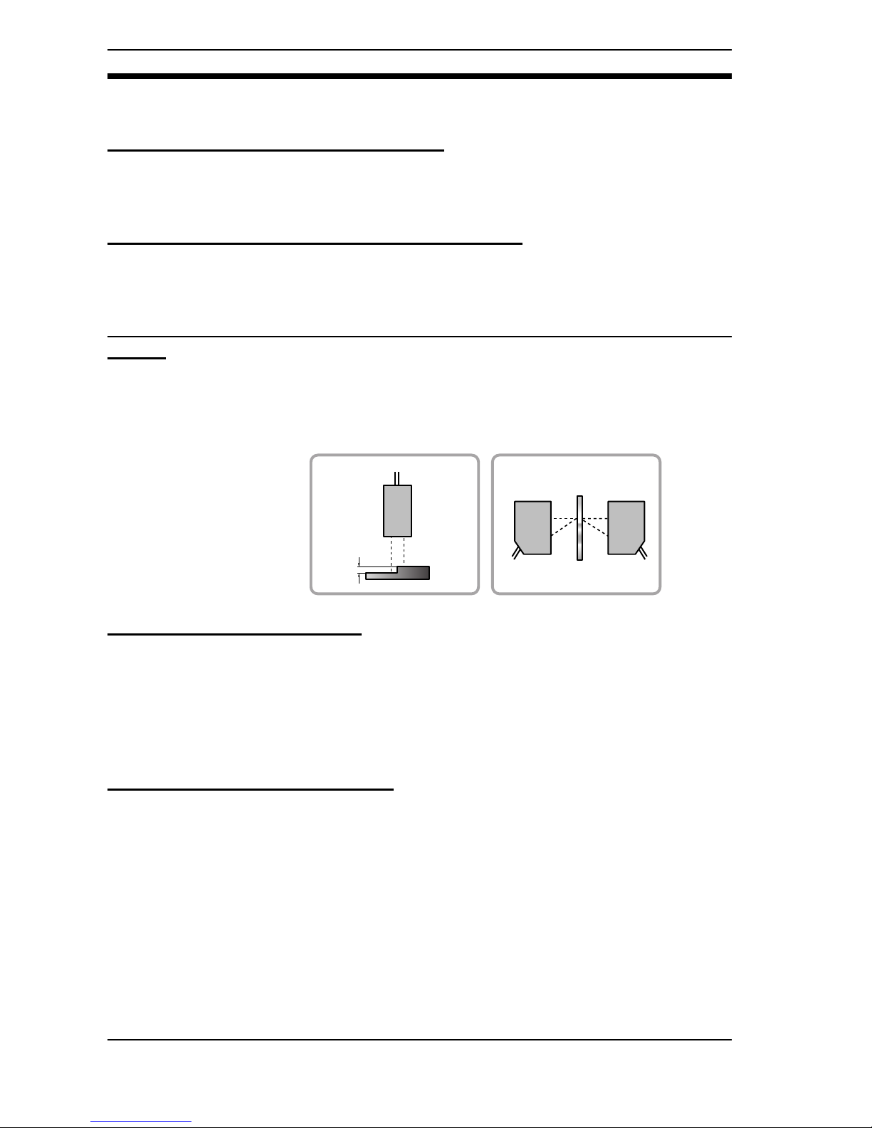
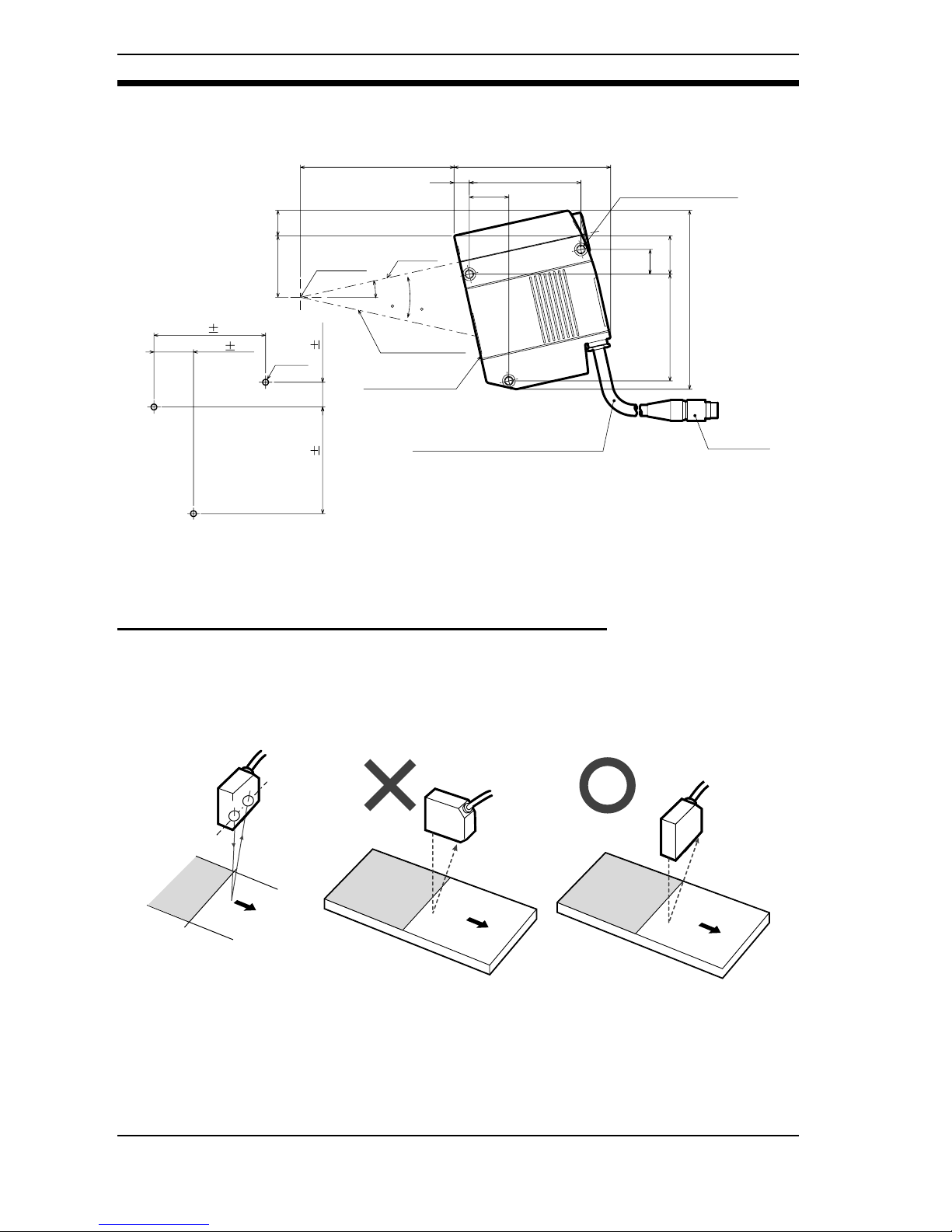
3-2-3 Mounting Orientation
Boundaries between Different Colors and Textures
If there are parts of the workpiece where the color or texture are significantly different, measurement errors can be reduced by mounting the Sensor in the way
shown below, i.e., so that the plane containing the emission axis and the reception axis is parallel to the boundary between the contrasting sections of the
workpiece.
Connector
Three,
M4
68.3
Mounting Hole
Cutout Dimensions
95.9
94
68.3
24.2
65.3
23.5
37.7 15.6
15.2
109.6
Vinyl-insulated round cable 6.8 dia.
Standard length 2m
9.3
Emission
axis
Reception axis
Reference plane
25
12.5
Measurement
center
Three, 4.5-dia. holes
24.2
65.3 15.2
(Unit: mm)
0.1
0.1
0.1 0.1
Boundary
Reception axis
Emission axis
Mounting the Sensor Section 3-2
Page 56

55
Mounting Near Walls
Errors will occur if light reflected off a wall surface is received by the Sensor. If it
is not possible to mount the Sensor away from the wall, mount in the way shown
below, i.e., so that the plane containing the emission axis and the reception axis
is parallel to the wall surface. Also, applying matt black coating to the wall surface will help to reduce the amount of light reflected.
Narrow Grooves or Indentations
If measurement is performed in an indentation between two walls, or in a
groove, mount the Sensor in the way shown below, i.e., so that the path along
the emission and reception axes is not interrupted by a wall.
Level Differences
When measuring workpieces with level differences, the influence of the level difference can be minimized by mounting the Sensor so that the plane containing
the emission axis and the reception axis is parallel to the boundary between the
different levels.
Mounting the Sensor Section 3-2
Page 57

56
Rotating Workpieces
When measuring rotating workpieces, the influence of position displacement
and blurring of the rotating workpiece can be minimized by mounting the Sensor
so that the plane containing the emission axis and the reception axis is parallel
to the axis of rotation.
Thickness Measurement
When measuring the thickness of boards, select the Sensor mounting method
according to the board material.
Workpiece
Opaque
Transparent
Example: Glass
Diffuse reflection
Example: Ceramic
Specular reflection Example:
Stainless steel
Sensor mounting
status
Diffuse reflection
mounting status
Mirror reflection mounting status
Controller settings
Workpiece
Workpiece
Mounting the Sensor Section 3-2
Page 58

57
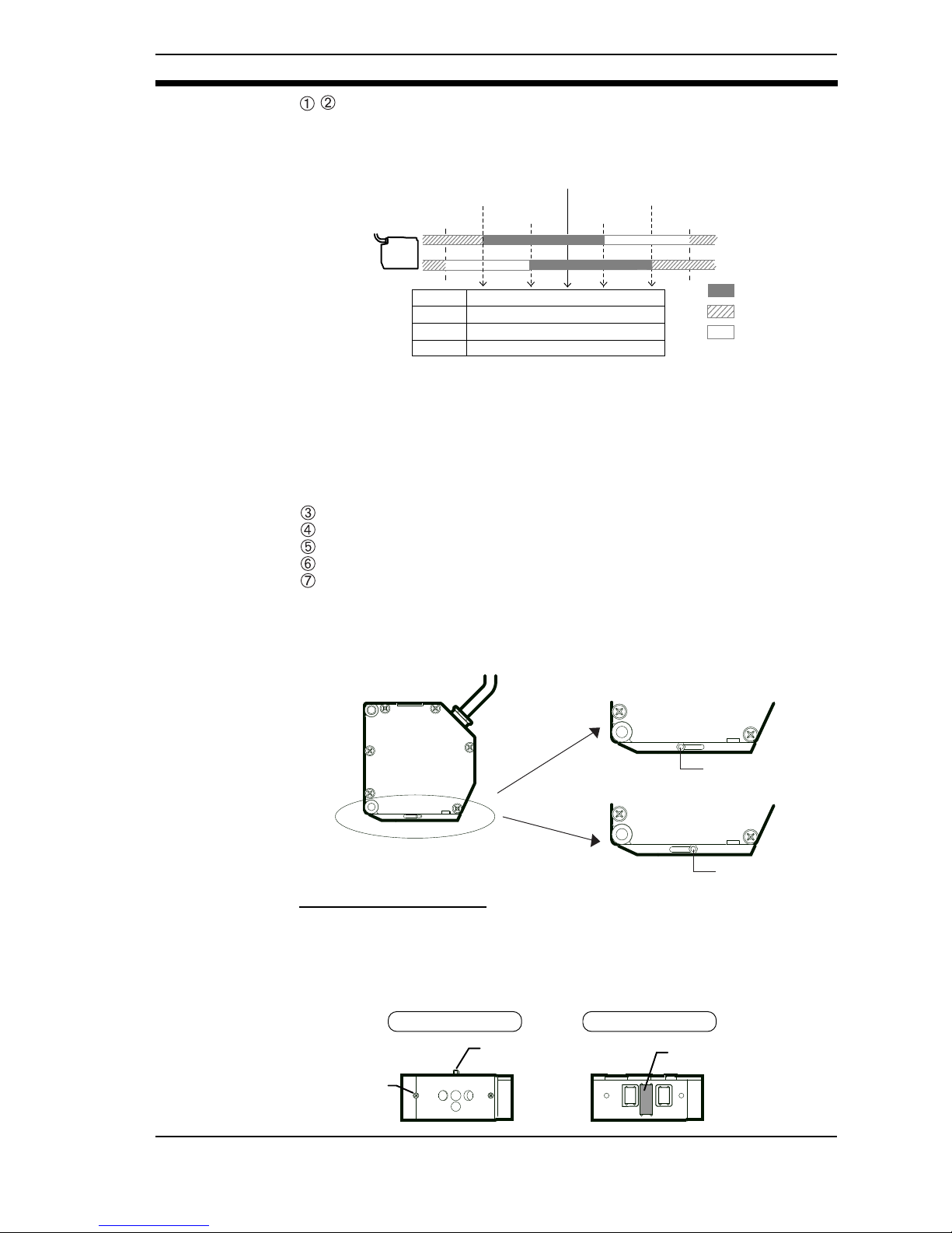
Projections
When measuring the tops of projections on the workpieces, mount the Sensor
so that the entire projection passes through the line beam.
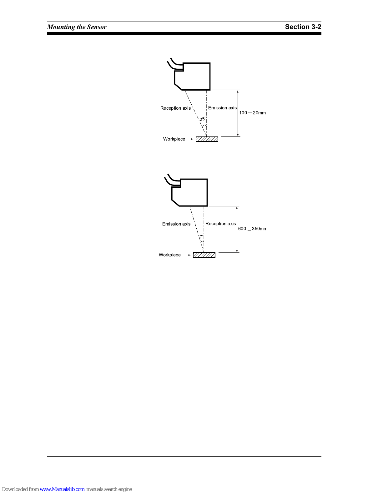
3-2-4 Mounting Distance
After selecting the Sensor mounting status in the menu item Environment,
mount the Sensor in a location where the status can be measured correctly.
For more details, refer to page 140 in the Operation Manual.
When using Non-visual Mode, refer to page 55.
Diffuse Reflection
Super-precision Model: Z300-S2T
High-precision Model: Z300-S5T
Mounting the Sensor Section 3-2
Page 59
58
Long-range Model: Z300-S10
Super Long-range Model: Z300-S60
Mounting the Sensor Section 3-2
Page 60

59
Mirror Reflection
Super-precision Model: Z300-S2T
High-precision Model: Z300-S5T
Long-range Model: Z300-S10
CHECK It is recommended that Sensor mounting is performed while monitoring the
amount of received light in the menu item Check position.
For details, refer to page 118 in the Operation Manual.
Mounting the Sensor Section 3-2
Page 61

60
3-2-5 Mutual Interference
When using 2 or more Sensors mounted adjacently, mutual interference will not
occur as long as the spots (shown below) for other Sensors are outside the
shaded areas.
Z300-S2T
Z300-S5T
Mounting the Sensor Section 3-2
Page 62

61
Z300-S10
Z300-S60
Mounting the Sensor Section 3-2
Page 63

62
Page 64

63
SECTION 4
Non-visual Mode
In Non-visual Mode, Z300 operation is performed according to the DIP switch settings without using the menus.
Because the menus are not used, the monitor and console are not required. Make settings for the Sensor mounting status, sensitivity, and response time using the DIP switch on the Controller.
The way that the Z300's analog outputs are used is set at the Linear Sensor Controller. For details, refer to the
operation manual for the Linear Sensor Controller connected.
4-1 Restrictions . . . . . . . . . . . . . . . . . . . . . . . . . . . . . . . . . . . . . . . . . . . . . . . . . . . . . . . . . . . 64
4-2 DIP Switch Settings. . . . . . . . . . . . . . . . . . . . . . . . . . . . . . . . . . . . . . . . . . . . . . . . . . . . . 65
4-2-1 Switching to Non-visual Mode. . . . . . . . . . . . . . . . . . . . . . . . . . . . . . . . . . . 65
4-2-2 Selecting the Sensor Setting Status . . . . . . . . . . . . . . . . . . . . . . . . . . . . . . . 66
4-2-3 Setting the Sensor’s Sensitivity . . . . . . . . . . . . . . . . . . . . . . . . . . . . . . . . . . 69
4-2-4 Selecting the Analog Output Response Time. . . . . . . . . . . . . . . . . . . . . . . . 69
4-2-5 Selecting the Output Method for Measurement Failure. . . . . . . . . . . . . . . . 70
Page 65

64
4-1 Restrictions
If the DIP switch setting is changed to NON VISUAL, the Controller's settings
can be changed using the DIP switch without having to connect a monitor or a
console.
Notice Turn OFF the power supply before changing the DIP switch settings.
The restrictions that apply when using the Z300 in Non-visual Mode are provided below.
- Measurement conditions set using the monitor and console are disabled.
- Even if a monitor and console are connected, console operations will have
no effect.
- Only 1 Sensor can be connected. It must be connected to SENSOR 0.
- Measurement is based on the following conditions.
- Sampling time: 0.96 ms
- Smoothing: None
- Noise removal: None
- Output: Analog output only
- Input: LD-OFF input only
- The settings that can be changed are as follows.
- The Sensor mounting status can be selected.
- The Sensor's sensitivity can be set.
- The response time for analog outputs can be selected.
- The output method for measurement failure can be selected.
Refer to page 55 for details of setting methods.
Restrictions Section 4-1
Page 66
65
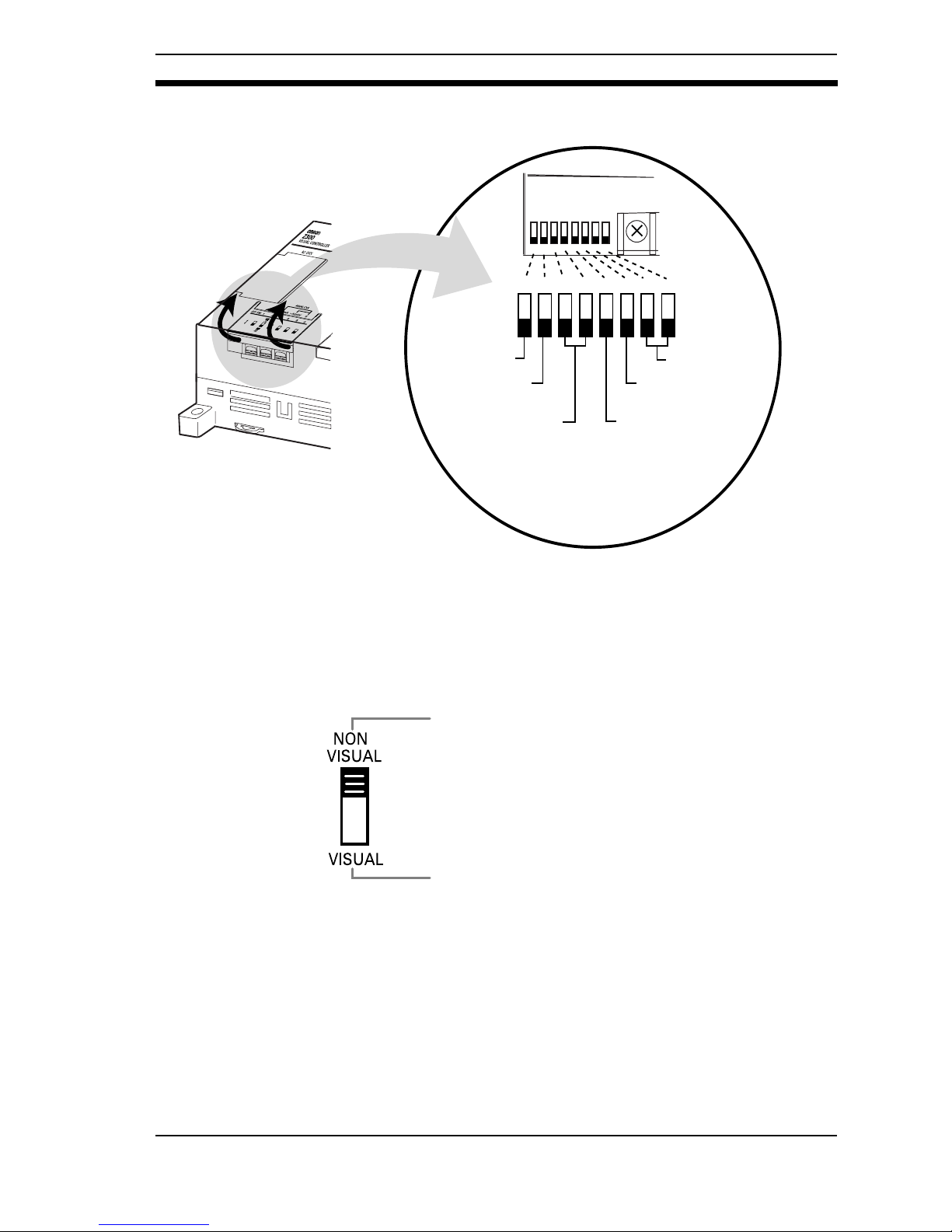
4-2 DIP Switch Settings
Notice Turn OFF the power supply before changing the DIP switch settings.
4-2-1 Switching to Non-visual Mode
Mode
Sensor mounting
status
Not used
Sensitivity
Analog output
response time
1234567
8
123 4 567 8
Output method for
measurement failure
Set when a Linear Sensor Controller is connected instead of a
monitor and console. Making this setting enables the other DIP
switch settings.
Set when using a monitor and console. Making this setting allows measurement conditions to be set on the console using
the menu items displayed on the monitor screen. Waveform
measurement results can also be displayed on the monitor.
Other DIP switch settings are disabled.
DIP Switch Settings Section 4-2
Page 67
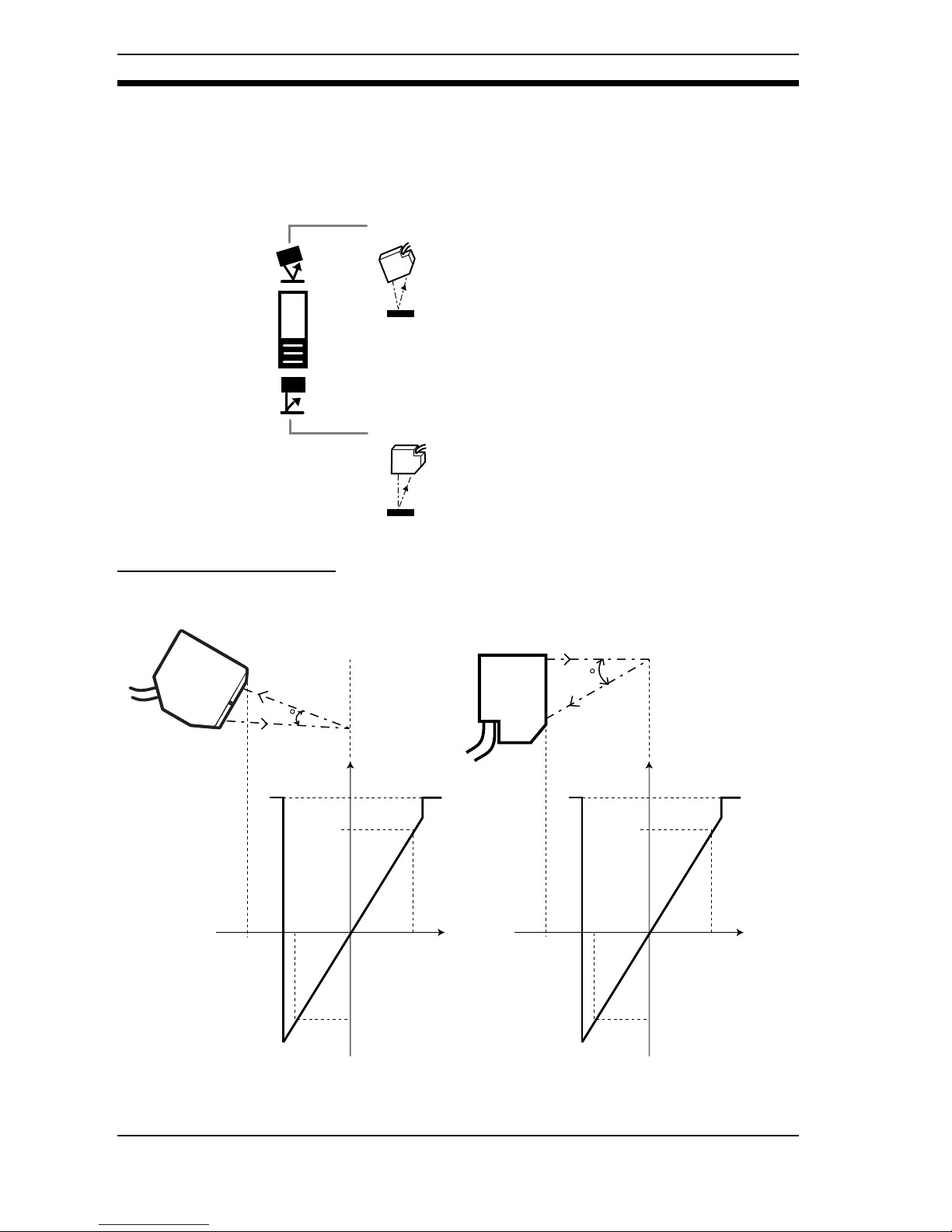
66
4-2-2 Selecting the Sensor Setting Status
The analog output appropriate for the mounting status is set. Measurement at
close to the actual dimensions is possible immediately after mounting.
Adjust the mounting position while monitoring the values of the Linear Sensor
Controller connected.
Output Characteristics
Diffuse Reflection
Mirror reflection
Light that is regularly reflected at the workpiece is
received directly. With this method, measurement
is possible even for shiny workpieces, such as
metallic workpieces.
Diffuse reflection
Light is emitted at the workpiece in a direction
perpendicular to its surface, and diffusely reflected light in the reflected light is received. This
method enables measurement over a wide range.
Measurement
distance
(mm)
30
0
50
(0V)
(5V)
(-5V)
55
45
4mA
0mA
20mA
(6V)
26mA
Analog outputAnalog output
Z300-S5T
Measurement
distance
(mm)
50
0
5.2
(0V)
(5V)
(-5V)
6.2
4.2
4mA
0mA
20mA
(6V)
26mA
Z300-S2T
DIP Switch Settings Section 4-2
Page 68

67
Mirror Reflection
7
0
600
(0V)
(5V)
(-5V)
950
250
Measurement
distance
(mm)
4mA
0mA
20mA
(6V)
26mA
Analog output
Z300-S60
25
0
100
(0V)
(5V)
(-5V)
120
80
Measurement
distance
(mm)
4mA
0mA
20mA
(6V)
26mA
Analog output
Z300-S10
Measurement
distance
(mm)
15
0
44
(0V)
(5V)
(-5V)
48
40
4mA
0mA
20mA
(6V)
26mA
Analog output
Z300-S5T
Measurement
distance
(mm)
25
0
20
[16]*
(0V)
(5V)
(-5V)
21
[17]*
19
[15]*
4mA
0mA
20mA
(6V)
26mA
Analog output
Z300-S2T
*Figures in [ ] are for measurement with the beam cover attached.
DIP Switch Settings Section 4-2
Page 69

68
!"#
DIP Switch Settings Section 4-2
Page 70

69
4-2-3 Setting the Sensor's Sensitivity
Set the sensitivity while monitoring the values on the Linear Sensor Controller
connected.
4-2-4 Selecting the Analog Output Response Time
The response time is a measure of the speed with which analog displacement
output responds to a discrete change in the displacement amount. It is the time
taken for the output level to change from 10% to 90% of the total change in level
when rising or falling.
Measurement is performed at the set sensitivity.
This method is effective if there are no sudden changes
in the color, material, or orientation of the workpiece.
Select from two possible settings.
The sensitivity is automatically adjusted to the optimum
level for the workpiece.
This method is effective if the color, material, or orientation of the workpiece changes.
It may not be possible to obtain measurement results
while the sensitivity is changing.
High sensitivity
Set when measuring workpieces with a low reflection
factor, such as black paper or black rubber.
Low sensitivity
Set when measuring workpieces with a high reflection
factor.
90%
90%
10%
10%
Response time Response time
Displacement amount
Displacement output
0.96 ms (The results of measurements taken once every
0.96 ms are updated and output every 0.96 ms.)
61.44 ms (The average of 64 results of measurements taken once every 0.96 ms are updated and output every 0.96
ms.)
DIP Switch Settings Section 4-2
Page 71

70
4-2-5 Selecting the Output Method for Measurement Failure
Select the way outputs operate when measurement is not possible due, for
example, to excessive or insufficient light density. Select the output method
while monitoring the values of the Linear Sensor Controller connected.
Locks at 22 to 26 mA or 6 V.
When set to HOLD
Holds previous data
When set to CLAMP
Transparent film
Analog value
Time
Example
Hold the previous measurement result.
Set to HOLD to disregard instances when measurement is not
possible due, for example, to excessive or insufficient light
density.
DIP Switch Settings Section 4-2
Page 72

71
SECTION 5
Maintenance
This section explains maintenance procedures for ensuring the Z300's performance.
Page 73

72
5 Maintenance
In order to ensure performance, carry out the maintenance procedures given
below.
Notice -Turn OFF the power and take safety precautions before conducting inspec-
tions. Electric shock can result from attempting safety inspections with the
power turned ON.
- Do not use thinners or benzene to clean the Z300.
5-1 Cleaning
- Remove dirt on equipment by gently wiping with a soft cloth.
Optical Filter on Front Panel of Sensor
- Use a blower brush (used to clean camera lenses) to blow large dust particles from the surface. Do not blow the dust away with your mouth.
- Use a soft cloth (for lenses) with a small amount of alcohol to remove the
remaining dust.
Notice Do not use a scrubbing action when cleaning as scratches on the filter could
result in the Sensor malfunctioning.
5-2 Regular Inspections
Inspection point Details
Tools
required
Power supply The voltage measured at the power sup-
ply terminals must be 24 VDC +10%/
-10%.
Circuit tester
Ambient
temperature
The operating ambient temperature inside
the cabinet must be between 0 and 50°C.
Thermometer
Ambient
humidity
The operating ambient humidity inside
the cabinet must be between 35% and
85%.
Hygrometer
Installation Each component must be firmly secured.
Each cable connector must be correctly
inserted and locked.
Phillips screwdriver
Cleaning Section 5-1
Page 74

73
SECTION 6
Troubleshooting
This section provides information on hardware errors that may occur with the Z300. Refer to this section before
requesting service from your OMRON representative.
Page 75

74
6 Troubleshooting
This section provides information on hardware errors and remedies to be taken.
Refer to this section before requesting service from your OMRON representative.
6-1 Connection Errors
6-1-1 The Power Indicator is Not Lit.
The Power Supply is not connected properly.
The 24-VDC (21.6 to 26.4-VDC) supply voltage has dropped.
6-1-2 The Video Monitor is Blank.
The power to the Video Monitor is not ON.
The Monitor Cable is not connected properly.
The Video Monitor is malfunctioning.
When using an Liquid Crystal Monitor, the power supply capacity is insufficient.
6-1-3 Cannot Make Key Inputs from the Console.
The Console Cable is not correctly connected.
The DIP switch is set to NON VISUAL.
6-1-4 No Images are Displayed.
The Sensor cable is not connected to the Controller correctly.
There is no workpiece inside the measurement range.
The Sensor is not mounted in the correct position.
6-1-5 The Video Monitor Image is Not Clear.
There is electric noise entering from the power supply or cables.
The Monitor Cable is not connected properly.
Connection Errors Section 6-1
Page 76

75
6-2 Terminal Block Errors
6-2-1 Trigger Signals (Input Signals) are Not Received.
The cables are not correctly wired.
The signal line is disconnected.
The Z300 is not in RUN mode.
6-2-2 Signals cannot be Output Externally.
The trigger signal has not been input.
The cables are not correctly wired.
The signal line is disconnected.
The Z300 is not in RUN mode.
6-3 RS-232C Communication Errors
6-3-1 No Communications are Possible.
The cables are not correctly wired.
The Z300's communications specifications do not match those of the external
device.
The Z300 is not in RUN mode.
6-3-2 The Unit Operates Well Initially, But After a While There is No
Response from the Z300.
The reception buffer on the external device (e.g., personal computer) is full.
Check that settings allow the data to be properly received.
Terminal Block Errors Section 6-2
Page 77

76
Page 78

77
SECTION 7
Appendix
This section provides the specifications and dimensions of the Z300 and its peripheral devices.
7-1 Specifications and Dimensions . . . . . . . . . . . . . . . . . . . . . . . . . . . . . . . . . . . . . . . . . . . . 78
7-2 Laser Product Classifications . . . . . . . . . . . . . . . . . . . . . . . . . . . . . . . . . . . . . . . . . . . . . 88
Page 79

78
7-1 Specifications and Dimensions
7-1-1 Sensor
Z300-S2T
Z300-S5T
42.8
12.5dia.
42.8
12.5dia.
Specifications and Dimensions Section 7-1
Page 80

79
Z300-S10
Z300-S60
42.8
12.5dia.
42.8
12.5dia.
Sensor Section 7-1
Page 81
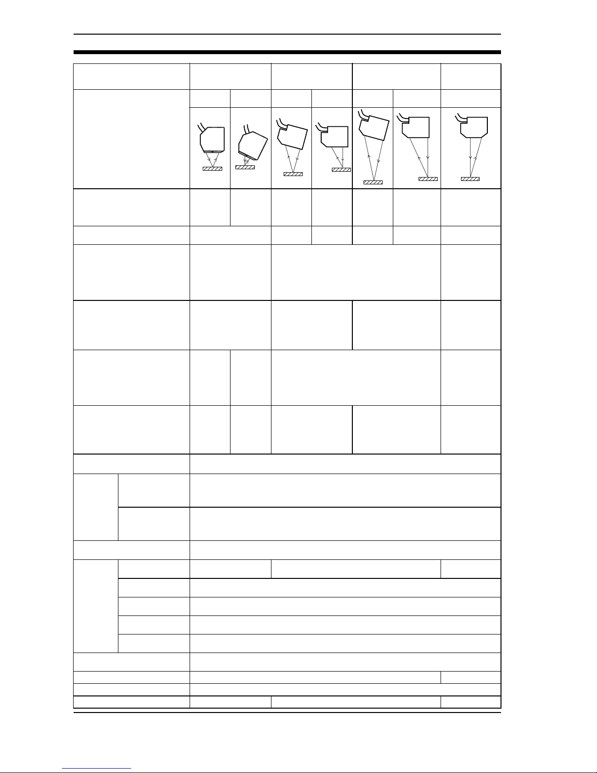
80
Model Z300-S2T
(Super-precision
Model)
Z300-S5T
(High-precision
Model)
Z300-S10
(Long-range Model)
Z300-S60
(Super Long-
range Model
RUN Mode Mirror
reflection
Diffuse
reflection
Mirror
reflection
Diffuse
reflection
Mirror
reflection
Diffuse
reflection
Diffuse reflection only
Distance to measurement
center
20mm
(with beam
cover
attached: 16
mm)
±5.2mm ±44mm ±50mm ±94mm ±100mm ±600mm
Measurement range ±1mm ±4mm ±5mm ±16mm ±20mm
±350
(F.S.700mm)
Light source
Visible-light semiconductor laser
(Wavelength: 650
nm, 1 mW max.,
Class 2)
Visible-light semiconductor laser (Wavelength: 670 nm, 1 mW max., Class 2)
Visible-light
semiconductor laser
(Wavelength:
658nm,
15mWmax.,
Class 3B)
Beam dimensions (See
note1.)
20µm
× 300µm
(200µm*) TYP. (distance to measurement center)
*Measurement
region.
30µm
× 400µm TYP.
(distance to measurement center
60µm
×1000µm TYP.
(distance to measurement center)
0.3 mm
×16
(10.3*)mm (at
500 mm)
* Measurement region
Linearity
±0.05%
F.S. (See
note 3.)
±0.05%
F.S. (See
note 2.)
±0.1% F.S. (See note 4.)
±0.07%
F.S.(250 to
750 mm)
±0.1%
F.S.(750 to
950 mm)
(See note 4.)
Resolution
0.4µm
(See
notes 5
and 6.)
0.4µm
(See
notes 5
and 6.)
0.4µm
(See notes 7 and 9.)
1µm
(See notes 7 and 8.)
8µm
(at 350 mm)
40µm
(at 600mm)
(See notes 7
and 8.)
Sampling period
(See note 10.)
540µs
LED indicators
NEAR indicator
Lights if the workpiece is close to the measurement center or is on the near side of
the measurement center and inside the measurement region.
Flashes if the workpiece is outside the measurement region or if the density is
excessive or insufficient.
FAR indicator
Lights if the workpiece is close to the measurement center or is on the far side of
the measurement center and inside the measurement region.
Flashes if the workpiece is outside the measurement region or if the density is
excessive or insufficient.
Temperature characteristic
(See note 11.)
±0.01%F.S./°C
Environment
resistance
Degree of protection
IP64 IP67
IP66
(See note12.)
Ambient operating illumination
Illumination at light-receiving surface: 3,000l
× max., incandescent light
Ambient temperature
Operating: 0 to +50°C (with no icing or condensation)
Storage: -15 to +60°C (with no icing or condensation)
Ambient humidity
Operating and storage: 35% to 85% (with no condensation)
Vibration resistance
10 to 150Hz (double amplitude: 0.35 mm) for 8min each in X, Y, and Z directions
Materials
Controller: Die-cast aluminum/Cable sheathing: Heat-resistant chlorinated vinyl
Connector: zinc alloy and brass
Cable length 2m 50cm
Minimum bending radius 68mm
Weight Approx. 350g Approx. 600g Approx. 550g
Sensor Section 7-1
Page 82

81
Note 1: Defined at 1/e
2
(13.5%) of the density at the light center. Light may, however, be
present outside this range and if the reflection factor of the light around the workpiece is high compared to the workpiece, measurement may be affected.
Note 2: Error with respect to the theoretical line representing the displacement output for
measurement of OMRON standard SUS blocks. The linearity varies with the
type of workpiece.
Note 3: Error with respect to the theoretical line representing the displacement output for
measurement of OMRON standard quartz glass. The linearity varies with the
type of workpiece.
Note 4: Error with respect to the theoretical line representing the displacement output for
measurement of OMRON standard white alumina ceramics. The linearity varies
with the type of workpiece.
Z300-S10
Note 5: Displacement conversion value for peak-to-peak of displacement output. These
figures are for measurement of OMRON standard quartz glass (mirror reflection)
or OMRON standard SUS blocks (diffuse reflection) at the measurement center.
In magnetic fields, it may not be possible to maintain resolution performance
characteristics.
Note 6: These figures are for when the Sensor is connected to the Z300-VC10EV3, the
average number of measurements is 256, and M command RS-232C output is
used.
Note 7: Displacement conversion value for peak-to-peak of displacement output (for
measurement of OMRON standard white alumina ceramic at the measurement
center).
In strong magnetic fields, it may not be possible to maintain resolution performance characteristics.
Note 8: With the Z300-VC10EV3, at an average number of measurements of 64, and M
command RS-232C output is used.
Note 9: With the Z300-VC10EV3, at an average number of measurements of 512, and
M command RS-232C output is used.
Note 10: Value for measurement with 1 line (high speed) set in CCD Mode.
Note 11: Value for measurement with the space between the Sensor and the workpiece
(Z300-S5/S10/S60: white alumina ceramic; Z300-S2: quartz glass) secured with
an aluminum jig.
Note 12: Enquire separately about products conforming to IP67.
0.1%max.
80mm
120mm
Distance
120mm
80mm
Digital output
Sensor Section 7-1
Page 83

82
7-1-2 Controller
Z300-VC10EV3/Z300-VC15EV3
General Specifications
Model Z300-VC10EV3 Z300-VC15EV3
Input/output type NPN PNP
Supply voltage 21.6 to 26.4 VDC (including ripple)
Current consumption 1A max. (with 2 Sensors connected) (See note 1.)
Insulation resistance 20 MΩ min. between all DC external terminals and GR terminal (100
VDC Megger, with internal surge absorber removed)
Dielectric strength 1,000 VAC, 50/60 Hz between all DC external terminals and GR ter-
minal (with internal surge absorber removed)
Leakage current 10mA max.
Noise resistance 1,500 Vp-p; Pulse width: 0.1µs/1µs;Rising edge: 1-ns pulse
Vibration resistance 10 to 150 Hz (double amplitude: 0.1 mm) for 8 min each in X, Y, and
Z directions
Shock resistance
200m/s
2
, 3 times each in 6 directions
Ambient temperature Operating: 0 to +50°C (with no icing or condensation)
Storage: -15 to +60°C (with no icing or condensation)
Ambient humidity Operating and storage: 35% to 85% (with no condensation)
Ambient environment No corrosive gases
Ground Ground the Z300’s ground terminal to less than 100Ω
Degree of protection IEC60529 IP20 (in-panel)
Case material Controller: ABS
195
83.7
20.2
Indicators
10
10
98.1
24.5
20
185
81.71
23.6
75.5
87.9
3.85
148.38
3.85
99.5
Four, 4.5 dia.holes
(Unit: mm)
Connector
(32.5)
4.1
(66.5)
8
50
44.8
110
100
90
35.3
25.1
53.1
36.2
8
4
23.3
12.5dia.
8 7.7=61.6
9 7.7=69.3
9 7.7=69.3
9 7.7=69.3
2 7.62=15.24
Controller Section 7-1
Page 84

83
Performance specifications
Note 1: Average current at normal operation after power is turned ON.
Note 2: For measurement at an average number of times of 64 with an OMRON K3AS
Linear Sensor Controller connected.
Item Visual Mode Non-visual Mode
Number of Sensors
that can be mounted
21
Number of scenes 16 1
Image memory function
NG images: 20 scenes max.; Surrounding
images: 4 scenes max.; Workpiece display
images: 4 scenes max.
——
Processing method Gray center of gravity, edge centering Edge centering
Pre-image processing Noise removal, smoothing None
Averaging/filtering
Average number of times (12 stages, 1 to 4,096
times), HPF (high pass filter), Median
Average number of times
(SLOW: 64 times; FAST:
1 time)
Light intensity tracking function
Automatic (The light intensity tracking range can
be specified.)
Fixed (Select from 32 stages.)
Automatic (The light
intensity tracking range
can not be specified.)
Fixed (Select either HIGH
or LOW.)
Applications
Select from the following 8 types:
Surface displacement, spot displacement, maximum height, groove/indentation, level difference,
transparent workpiece thickness, level difference
(2 Sensors), or thickness (2 Sensors).
——
Region specification
Region specification of line beam and displacement direction is possible.
——
Two region measurement modes
Absolute coordinate mode and relative coordinate mode
——
Hold functions
Sampling, peak, bottom, peak-to-peak, average,
and length
——
Two Sensor measurement modes
Simultaneous measurement and alternate measurement
——
Measurement data 4 outputs per scene 1 output
Equations
The following operations are possible for outputs
0 to 3:
K+A, K-A, K+(A+B), K+(A-B), and K-(A+B)
A and B: Specified measurement points
K: Freed constant
——
Results output
Judgement output (HIGH, PASS, LOW, ERROR)
RS-232C output
Terminal block output
Measurement value output (measurement value)
RS-232C output
Terminal block output
Analog output
Analog output
Terminal block
11 input points:TRIGGER
, HOLD-RESET, LDOFF, ALL-ZERO, ZERO0, ZERO1, RESET, and
DI 0
to DI 3
21 output points: DO0 to DO20
LD-OFF
Monitor interface 1 channel (for pin jack or overscan monitor) ——
Analog output resolution
The full scale for output can be divided into a maximum of 40,000 gradations.
Resolution (See note 2.) *0.25 mV (±5V)
0.4µA (4 to 20µA)
Weight Approx. 700 g (Controller only)
Controller Section 7-1
Page 85

84
7-1-3 Console
Z300-KP
General Specifications
Vibration resistance 10 to 150 Hz; single-amplitude: 0.15 mm, 4 times for 8 minutes
each in 3 directions
Shock resistance
196m/s
2
; 3 times each in 6 directions
Ambient temperature Operating: 0 to 50°C (with no icing or condensation)
Storage: -25 to 65°C (with no icing or condensation)
Ambient humidity Operating and storage: 35% to 85% (with no condensation)
Ambient environment No corrosive gases
Degree of protection IEC60529 IP20 (in-panel)
Minimum bending radius 75mm
Materials Console: ABS
Cable sheathing: Heat-resistant chlorinated vinyl
Connector: PC and PBT
Weight Approx.135g
Console Section 7-1
Page 86

85
7-1-4 Cable
F150-VM
General Specifications
Vibration resistance 10 to 150 Hz; single-amplitude: 0.15 mm, 4 times for 8 minutes
each in 3 directions
Shock resistance
196m/s
2
; 3 times each in 6 directions
Ambient temperature Operating: 0 to 50°C (with no icing or condensation)
Storage: -25 to 65°C (with no icing or condensation)
Ambient humidity Operating and storage: 35% to 85% (with no condensation)
Ambient environment No corrosive gases
Materials Cable sheathing: Super heat-resistant chlorinated vinyl
Connector: PVC
Minimum bending radius 50 mm
(Unit: mm)
Cable Section 7-1
Page 87

86
7-1-5 Color Liquid Crystal Monitor
F150-M05L
General Specifications
Performance specifications
Supply voltage 20.4 to 26.4 VDC (including ripple)
Current consumption 700 mA max.
Vibration resistance
10 to 150 Hz; single-amplitude: 0.1 mm; maximum acceleration: 15 m/s
2
, 10
times for 8 minutes each in 3 directions
Shock resistance
150 m/s
2
, 3 times each in 6 directions
Ambient temperature Operating: 0 to 50°C (with no icing or condensation)
Storage: -25 to 65°C (with no icing or condensation)
Ambient humidity Operating and storage: 35% to 85% (with no condensation)
Ambient environ-
ment
No corrosive gases
Materials Case: ABS/PC Display surface: PMMA (Acrylic)
Weight Approx. 1 kg
Panel size 5.5 inches (111.36 × 83.52 mm (H × V))
Panel type TFT color liquid crystal
Resolution 320 × 240 dots
Image pitch 0.348 × 0.348 mm (H × V)
Contrast 85:1 (typical)
Viewable angle 25° up/down and 50° left/right (with a contrast ratio > 10)
Luminance
250cd/m
2
(typical)
Backlight Cold cathode fluorescent light
Response speed 60 ms max.
Input signal NTSC composite video (1.0 V/75 Ω termination)
Weight Approx. 610 g
POWER
SYNC
143
(145)
(155)
132
50 min.
(46 max.)
Mounting plate thickness:
1.6 to 4.8
(5.5)
(100)
185
174
Mounting bracket
F150-VM Monitor cable
42.2
133.5
175.5
Panel opening dimensions
+0.5mm
0
+0.5mm
0
(Unit: mm)
Color Liquid Crystal Monitor Section 7-1
Page 88

87
7-1-6 Video Monitor (Monochrome)
Recommended model: OMRON F150-M09 B/W Video Monitor
General Specifications
Performance specifications
Power supply voltage 85 to 264 V AC, 50/60 Hz
Power consumption 20 W max.
Vibration resistance 5 to 100 Hz in 3 directions, 10 minutes x 6 for each sweep
At a double-amplitude of 0.16 mm or an acceleration of 7.35 m/s
2
(whichever
is smaller)
Ambient temperature −10 to +50°C at operation, −20 to +65°C at storage (no freezing and
condensation)
Ambient humidity Operating and storage: 10 % to 90 % (no condensation)
Ambient
environment
No corrosive gases
Materials Front: ABS plastic
Metal part: SECC (galvanized steel sheet)
Weight Approx. 4.5 kg
CRT size 9 inches (164 (H) x 123 (V) mm)
CRT type CRT monochrome (medium persistence)
Resolution 800 TV lines min. (at center)
System Number of scanning lines: 600
Horizontal frequency: 15.75 kHz
Field frequency: 60 Hz
I/O impedance 75 Ω, high impedance (selectable)
I/O level and polarity Composite image signal: 1 V (peak to peak)
Image: 0.7 V (peak to peak), positive
Synchronization: 0.3 V (peak to peak), negative
Input signal NTSC composite video (1.0 V/75 Ω termination)
222
250
2335
143
(Unit: mm)
190
160
22
50
Video Monitor Section 7-1
Page 89

88
7-2 Laser Product Classifications
EN/JIS
FDA/ANSI
Class Description
Class 1 Safe inherently by engineering design.
Class 2 Low power in the visible spectrum (wavelength: 400 to 710 nm); eye protection
normally afforded by aversion responses.
Class 3A Direct intrabeam viewing with optical aids may be hazardous.
Power of less than 5 mW max. for visible spectrum.
Less than five times the output of the Class 1 for wavelengths other than the
visible spectrum.
Class 3B Direct intrabeam viewing may be hazardous.
It is not hazardous to view the pulse laser radiation that does not focus due to
scattered reflection and the power that allows safe viewing under certain conditions is less than 0.5 W.
Class 4 High power; diffused reflection may be hazardous and may lead to skin haz-
ards or fire.
Class FDA definition ANSI description
Class I/1
Limits applicable to devices that have
emissions in the ultraviolet, visible, and
infrared spectra, and limits below
which biological hazards have not
been established.
A Class 1 laser is considered to be
incapable of producing damaging radiation levels during operation and maintenance and is, therefore, exempt from
any control measures or other forms of
surveillance.
Class IIa/2a Limits applicable to products whose
visible emission does not exceed
Class I limits for emission durations of
1,000 seconds or less and are not
intended for viewing.
Class 2 lasers are divided into two
subclasses, 2 and 2a. A Class 2 laser
emits in the visible portion of the spectrum (0.4 to 0.7 µm) and eye protection
is normally afforded by the aversion
response including the blink reflex.
Class II/2 Limits applicable to products that have
emissions in the visible spectrum (400
to 710 nm) for emission durations in
excess of 0.25 second, providing that
emissions for other durations and/or
wavelengths do not exceed the Class I
limits. Class II products are considered
hazardous for direct long-term ocular
exposure.
Class IIIa/3a Limits to products that have emissions
in the visible spectrum and that have
beams where the total collectable radiant power does not exceed 5 milliwatts.
Class 3 lasers are divided into two
subclasses, 3a and 3b. A Class 3 laser
may be hazardous under direct and
specular reflection viewing conditions,
but the diffuse reflection is usually not
a hazard.
Class IIIb/3b Limits applicable to devices that emit in
the ultraviolet, visible, and infrared
spectra. Class IIIb products include
laser systems ranging from 5 to 500
milliwatts in the visible spectrum. Class
IIIb emission levels are ocular hazards
for direct exposure throughout the
range of the Class, and skin hazards at
the higher levels of the Class.
Class IV/4
Exceeding the limits of Class IIIb and
are a hazard for scattered reflection as
well as for direct exposure.
A Class 4 laser is a hazard to the eye
or skin from the direct beam and
sometimes from a diffuse reflection
and also can be fire hazard. Class 4
lasers may also produce laser-generated air contaminants and hazardous
plasma radiation.
Laser Product Classifications Section 7-2
Page 90

89
Requirements from Regulations and Standards
Manufacturer's Requirements
EN60825 (IEC60825) "Radiation Safety of Laser Products, Equipment Classification, Requirements and User's Guide"
With respect to the requirements of remote interlock connector, key control,
emission warning and attenuator, Class 3B laser products not exceeding five
times the AEL of Class 2 in the wavelength range of 400 to 700 nm are to be
treated as Class 3A laser products.
Note: This table is intended to provide a convenient summary of requirements. See
text of standard for complete requirements.
Requirements;
Sub-clause
Classification
Class 1 Class 2 Class 3A Class 3B Class 4
Description of
hazard class
Safe inherently
by engineering
design
Low power;
eye protection
normally
afforded by
aversion
responses
Same as Class
2. Direct intrabeam viewing
with optical
aids may be
hazardous
Direct intrabeam viewing
may be hazardous
High power;
diffused reflection may be
hazardous
Protective housing
Required for each laser product; limits access necessary for performance of
functions of the products
Safety interlock in
protective housing
Designed to prevent removal of the panel until accessible emission values are
below the AEL for the class assigned
Remote control
Not required
Permits easy addition of external interlock in laser installation
Key control
Not required
Laser inoperative when key is
removed
Emission warning
device
Not required
Give audible or visible warning
when laser is switched on or if
capacitor bank of pulsed laser
is being charged
Attenuator
Not required
Give means beside ON/OFF
switch to temporarily block beam
Location controls
Not required
Controls located so adjustment does not require
exposure to AEL above class 1 or 2
Viewing optics Emission from all viewing systems must be below Class 1 AEL's as applicable
Scanning Scan failure shall not cause product to exceed its classification
Class label Required word-
ing
Warning and explanatory labels and specified wording (Refer to
page 12)
Aperture label Not required Specified wording required
Service entry
label
Required as appropriate to the class of accessible radiation
Override interlock
label
Required under certain conditions as appropriate to the class of laser used
User information Operation manuals must contain instructions for safe use
Purchasing and
service information
Promotion brochures must reproduce classification labels; service manuals must
contain safety information
Medical products
Special calibration instructions required
Special calibration instructions,
means for measurement and
target-indicator required
Fibre optic Cable service connections require tool to disconnect if disconnection breaks pro-
tective housing and permits access above Class 1
Laser Product Classifications Section 7-2
Page 91

90
JIS C6802 "Radiation Safety Standards for Laser Products"
With respect to the requirements of remote interlock connector, key control,
emission warning and attenuator, Class 3B laser products not exceeding five
times the AEL of Class 2 in the wavelength range of 400 to 700 nm are to be
treated as Class 3A laser products.
Note: This table is intended to provide a convenient summary of requirements. See
text of standard for complete requirements.
Requirements;
Sub-clause
Classification
Class 1 Class 2 Class 3A Class 3B Class 4
Description of
hazard class
Safe inherently
by engineering
design
Low power; eye
protection normally afforded
by aversion
responses
Same as Class
2. Direct intrabeam viewing
with optical
aids may be
hazardous
Direct intrabeam viewing
may be hazardous
High power;
diffused reflection may be
hazardous
Protective housing
Required for each laser product; limits access necessary for performance of
functions of the products
Safety interlock
in protective
housing
Designed to prevent removal of the panel until accessible emission values are
below the AEL for the class assigned
Remote control Not required
Permits easy addition of external interlock in laser installation
Key control Not required
Laser inoperative when key is
removed
Emission warning
device
Not required
Give audible or visible warning
when laser is switched on or if
capacitor bank of pulsed laser
is being charged
Attenuator Not required
Give means beside On/Off
switch to temporarily block
beam
Location controls Not required
Controls located so adjustment does not require
exposure to AEL above class 1 or 2
Viewing optics Emission from all viewing systems must be below Class 1 AEL's as applicable
Scanning Scan failure shall not cause product to exceed its classification
Class label
Required wording
Warning and explanatory labels and specified wording (Refer to
page 12)
Aperture label Not required Specified wording required
Service entry
label
Required as appropriate to the class of accessible radiation
Override interlock
label
Required under certain conditions as appropriate to the class of laser used
User information Operation manuals must contain instructions for safe use
Purchasing and
service information
Promotion brochures must reproduce classification labels; service manuals must
contain safety information
Additional
requirements for
laser optical fibre
transmission system
Cable service connections require tool to disconnect if disconnection breaks protective housing and permits access above Class 1
Laser Product Classifications Section 7-2
Page 92

91
FDA (21 CFR1040.10 "Laser Products")
Abbreviations:
R: Required.
N/A: Not applicable.
S: Requirements: Same as for other products of that Class. Also see footnotes.
NP: Not permitted.
D: Depends on level of interior radiation.
Requirements Class (see note 1)
I IIa II IIIa IIIb IV
Performance (all laser products)
Protective
housing
R (see note 2) R (see note 2) R (see note 2) R (see note 2) R (see note 2) R (see note 2)
Safety interlock R
(see notes 3,4)R (see notes 3,4)R (see notes 3,4)R (see notes 3,4)R (see notes 3,4)R (see notes 3,4)
Location of
controls
N/A R R R R
Viewing optics R R R R R R
Scanning
safeguard
RRRRRR
Performance (laser systems)
Remote control
connector
N/A N/A N/A N/A R R
Key control N/A N/A N/A N/A R R
Emission
indicator
N/AN/ARRR
(see note 10)R (see note 10)
Beam attenuator N/A N/A R R R R
Reset N/A N/A N/A N/A N/A R
(see note 13)
Performance (specific purpose products)
Medical S S S S (see note 8) S (see note 8) S (see note 8)
Surveying, level-
ing, alignment
SSSSNPNP
Demonstration S S S S S
(see note 11)
(see note 11)
Labeling (all laser products)
Certification &
identification
RRRRRR
Protective
housing
D (see note 5) D (see note 5) D (see note 5) D (see note 5) D (see note 5) D (see note 5)
ApertureN/AN/ARRRR
Class warning N/A R (see note 6) R (see note 7) R (see note 9) R
(see note 12)R (see note 12)
Information (all laser products)
User information R R R R R R
Product literature N/A R R R R R
Service
information
RRRRRR
Laser Product Classifications Section 7-2
Page 93

92
Footnotes:
Note 1: Based on highest level accessible during operation.
Note 2: Required wherever & whenever human access to laser radiation above Class I
limits is not needed for product to perform its function.
Note 3: Required for protective housings opened during operation or maintenance, if
human access thus gained is not always necessary when housing is open.
Note 4: Interlock requirements vary according to Class of internal radiation.
Note 5: Wording depends on level & wavelength of laser radiation within protective
housing.
Note 6: Warning statement label.
Note 7: CAUTION logotype.
Note 8: Requires means to measure level of laser radiation intended to irradiate the
body.
Note 9: CAUTION if 2.5 mW cm
2
or less, DANGER if greater than 2.5 mW cm-2 .
Note 10: Delay required between indication & emission.
Note 11: Variance required for Class IIb or IV demonstration laser products and light
shows.
Note 12: DANGER logotype.
Note 13: Required after August 20, 1986.
Laser Product Classifications Section 7-2
Page 94
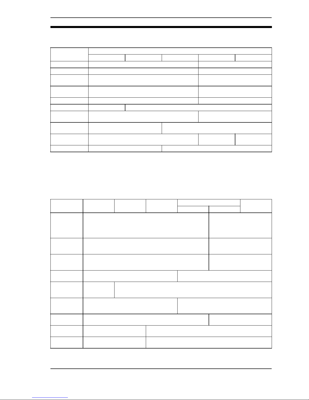
93
User's Requirements
EN60825 (IEC60825)
With respect to the requirements of remote interlock connector, key control,
beam attenuator, and emission indicator, Class 3B laser products not exceeding
five times the AEL of Class 2 in the wavelength range of 400 to 700 nm are to be
treated as Class 3A laser products.
Note: This table is intended to provide a convenient summary of requirements. See
text of standard for complete precautions.
JIS C6802
Note: *Class 3B applies to any laser beam with a power of 5 mW maximum in the visi-
ble range of the laser beam.
Requirements;
Sub-clause
Classification
Class 1 Class 2 Class 3A Class 3B Class 4
Remote interlock Not required Connect to room or door circuits
Key control Not required Remove key when not in use
Beam attenuator
Not required
When in use prevents inadvertent
exposure
Emission
indicator device
Not required Indicates laser in energized
Warning signs Not required Follow precautions on warning signs
Beam path Not required Terminate beam at end of useful length
Specular
reflection
No requirements Prevent unintentional reflections
Eye protection
No requirements
Required if engineering and administrative proce-
dures not practicable and MPE exceeded
Protective
clothing
No requirements
Sometimes
required
Specific
requirements
Training No requirements Required for all operator and maintenance personnel
Item Class 1 Class 2 Class 3A
Class 3B Class 4
3B* 3B
Remote
interlock
Not required
Connect the remote interlock
of the laser beam to the
emergency main interlock,
the interlock of the room, or
the interlock of the door.
Key control
Not required
Do not keep the key in the
lock when the laser beam is
not used.
Beam breaker
or attenuator Not required
Used to protect people from
accidental radiation by the
laser beam.
Warning sign
Not required
Post a proper warning sign on the door to the
room where laser beam equipment is installed.
Beam path
Not required
The laser beam must be terminated and, as a rule, must be enclosed. If the
laser beam is exposed, the vertical height of the beam must not be the
same as that of the eyes.
Mirror
reflection Not required
Appropriate optical elements must be securely
attached and you must be able to control the optical elements during laser radiation.
Eye protection
Not required
Use eye protectors except in
special, specified locations.
Protection
clothes
Not required
Wear protection clothes if exposure of the skin to the laser
beam may exceed the MPE of the skin.
Training
Not required
The laser system must be operated by only properly trained
people.
Laser Product Classifications Section 7-2
Page 95

94
ANSI Z136.1:1993 "American National Standard for the Safety Use of Lasers"
Note: LEGEND
X: Shall
• : Should
---: No requirement
✩ : Shall if enclosed Class 3b or Class 4
MPE: Shall if MPE is exceeded
NHZ: Nominal Hazard Zone analysis required
Control measures Classification
Engineering Controls 1 2a 2 3a 3b 4
Protective Housing XXXXXX
Without Protective Housing LSO shall establish Alternate Controls
Interlocks on Protective
Housing
✩✩✩✩XX
Service Access Panel ✩✩✩✩XX
Key Control --- --- --- --- • X
Viewing Portals --- --- MPE MPE MPE MPE
Collecting Optics MPE MPE MPE MPE MPE MPE
Totally Open Beam Path
--- --- --- ---
X
NHZ
X
NHZ
Limited Open Beam Path
--- --- --- ---
X
NHZ
X
NHZ
Enclosed Beam Path None is required if 4.3.1 and 4.3.2 fulfilled
Remote Interlock Connector --- --- --- --- • X
Beam Stop or Attenuator --- --- --- --- • X
Activation Warning Systems --- --- --- --- • X
Emission Delay --- --- --- --- --- X
Indoor Laser Controlled Area
--- --- --- ---
X
NHZ
X
NHZ
Class 3b Laser Controlled
Area
--- --- --- --- X ---
Class 4 Laser Controlled Area --- --- --- --- --- X
Laser Outdoor Controls
--- --- --- ---
X
NHZ
X
NHZ
Laser in Navigable Airspace --- --- --- • • •
Temporary Laser Controlled
Area
✩
MPE
✩
MPE
✩
MPE
✩
MPE
--- ---
Remote Firing & Monitoring --- --- --- --- --- •
Labels XXXXXX
Area Posting
--- --- --- •
X
NHZ
X
NHZ
Laser Product Classifications Section 7-2
Page 96

95
Index
C
CQM1-LSE, 46
D
DIN track, 48
DIP switch, 65
Distance to measurement center, 27, 29
F
F150-M05L, 86
F150-VM, 85
F300-M09, 87
G
Ground wiring, 35
H
High-precision Model, 50
K
K3AS, 45
K3NX, 46
K3TJ, 45
K3TS, 44
L
Line beam width, 50
Linear Sensor Controller, 43
Long-range Model, 50
M
Measurement range, 27, 29, 50
Mounting distance, 57
Mounting hole cutout dimensions, 51
Mounting orientation, 54
Mutual interference, 60
N
Non-visual Mode, 32, 63
P
Power supply, 35
R
Reference distance, 50
RS-232C, 41
S
Spot diameter, 50
Super long-range Model, 50
Super-precision Model, 50
T
Terminal block, 37
V
Visual Mode, 30
Z
Z300-KP, 84
Z300-S2T, 51, 53, 59, 60, 66, 67, 78, 80
Z300-S5T, 51, 53, 59, 60, 66, 67, 78, 80
Z300-S10, 52, 54, 58, 59, 61, 67, 68, 79, 80
Z300-S60, 52, 58, 61, 67, 79, 80
Z300-VC10EV3, 82
Page 97

96
Revision History
A manual revision code appears as a suffix to the catalog number on the front cover of the manual.
Cat. No. Z161-E1-03B
Revision code
The following table outlines the changes made to the manual during each revision. Page numbers
refer to the previous version.
Revision code Date Revised content
01 October 2001 Original production
01A April 2002 Some terms were changed.
02 March 2003
Information on safety precautions were added. Other minor
changes have been made.
03 May 2004
Page 5: Catalog numbers abbreviated.
Page 82: Reference to note 1 added.
Page 83: Reference to note changed and note 1 added.
Page 87: Page replaced.
03A July 2004
Pages 8, 9, and 10: Warranty and limitations of liability
information revised.
03B November 2004
Page 8: Suitability for use information added.
Pages 78 and 79: Minor changes to diagrams made.
Page 98

OMRON Corporation
Industrial Automation Company
Application Sensors Division
Sensing Devices and Components Division H.Q.
Shiokoji Horikawa, Shimogyo-ku,
Kyoto, 600-8530 Japan
Tel: (81)75-344-7068/Fax: (81)75-344-7107
Regional Headquarters
OMRON EUROPE B.V.
Sensor Business Unit
Carl-Benz Str. 4, D-71154 Nufringen,
Germany
Tel:(49)7032-811-0/Fax:(49)7032-811-199
OMRON ELECTRONICS LLC
1 East Commerce Drive, Schaumburg, IL 60173
U.S.A.
Tel:(1)847-843-7900/Fax:(1)847-843-8568
OMRON ASIA PACIFIC PTE. LTD.
83 Clemenceau Avenue,
#11-01, UE Square,
 Loading...