

Page 1
Y92F-55, Y92F-58, and Y92F-59
Draw-out Jigs
EN
INSTRUCTION MANUAL
To ensure safe usage of the product, thoroughly read and understand this Instruction Manual and keep it in a safe location so that it is
available for reference whenever required.
OMRON Corporation
© OMRON Corporation 2015 All Rights Reserved. 0194754-5B (Side-A)
ƔIntroduction
You can use the Draw-out Jig to remove the interior body of a Digital Controller mounted to a panel from the rear case
to perform maintenance without removing the terminal leads. You can also use the Draw-out Jig to remove the interior
body of a Digital Controller that is not yet mounted. These Draw-out Jigs can be used for draw-out-type E5ȏC,E5ȏD
The Digital Controller consists of an interior body and a rear case.Turn OFF the power supply before you attempt to
remove the interior body of the Digital Controller, and never touch nor apply shock to the terminals or electric
components.If the terminals are corroded, replace the rear case as well.
(1)
(1)
Rear case
Hook
Rear case
Align the arms
with the front
panel.
ƔDrawing Out the Interior Body of the Digital Controller to Replace It
1 Draw out the interior body from the rear case.
Y92F-55 (for G size:48h24PP)
(1)
Slowly insert the Draw-out Jig into the Draw-out Jig insertion holes
laterally until it clicks into place. (There is a hole at both the top and
bottom.) (If you attempt to draw out the interior body of the Digital
Controller when only one hook is engaged, the Digital Controller may be
damaged.)
(2) Pull out the Draw-out Jig together with the front panel. Do not pull
with excessive force. Slowly pull out the Digital Controller laterally. (If
you pull the interior body out at an angle, the Digital Controller may
be damaged.)
(3) After the interior body is free from the rear case, support the interior
body with one hand and draw it out slowly in a horizontal direction.
Y92F-58 (for C size48h48PP) or Y92F-59 (for E size:48h96PP or A size:96h96PP)
(1) Align the arms on the Draw-out Jig with the top of the front panel on
the Digital Controller and position it vertically.
(The Y92F-58 is shown in the figure.)
(2) Align the hooks on the Draw-out Jig with the Draw-out Jig insertion
holes on the Digital Controller and slowly insert the Draw-out Jig into
the Draw-out Jig insertion holes laterally until it clicks into place. (If
you attempt to draw out the interior body of the Digital Controller
when only one hook is engaged, the Digital Controller may be
damaged.)
(The Y92F-58 is shown in the figure.)
(3) Pull out the Draw-out Jig together with the front panel. Do not pull
with excessive force. Slowly pull out the Digital Controller laterally. (If
you pull the interior body out at an angle, the Digital Controller may be
damaged.)
(4) After the interior body is free from the rear case, support the interior
body with one hand and pull it out slowly in a horizontal direction.
Draw-out Jig
(2)
Draw-out Jig insertion holes
(3)
Front panel
(1)
Draw-out Jig insertion holes
Draw-out Jig insertion holes
Front panel
Arm
(1)
Draw-out Jig insertion holes
(2)
(2)
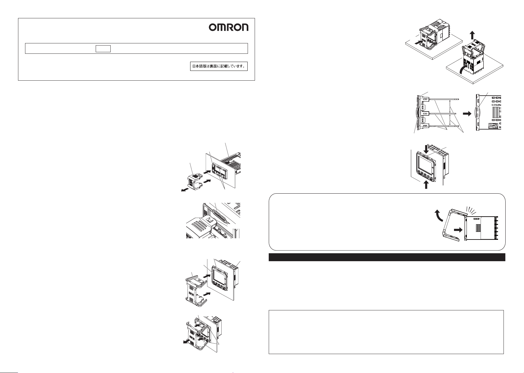
2 Prepare the new interior body.
(1) Place the Digital Controller flat on a table and slowly insert the
Draw-out Jig into the Draw-out Jig insertion holes laterally until it
clicks into place. (There is a hole at both the top and bottom.)
(The E5CC-D is shown in the figure.)
(2) Place the Digital Controller on a table facing upward.
(3) Hold the rear case with your hand and slowly draw out the interior
body in a vertical direction. If you draw out the interior body
horizontally while holding the Digital Controller in your hand, the
interior body will fall and may be damaged.
3 Insert the new interior body into the rear case.
(1) When inserting the interior body back into the rear case, make
sure the PCBs are parallel to each other, mount the sealing
rubber, and press the interior body toward the rear case and into
position, making sure that the sealing rubber does not move.
(2) When you press the Digital Controller into position, press down
on the rear case hooks so that the case hooks securely lock in
place. (There are rear case hooks at both the top and bottom of
the rear case.) If the Digital Controller is not correctly mounted
into the rear case, the rear case may not be waterproof. When
inserting the Digital Controller, do not allow the electronic
components to touch the rear case. (The E5CC-D is shown in the
figure.)
(1)
Top View
Case hooks
(2)
(2)
Sealing rubber position
PCBs
Removing the draw-out jig when only one hook is caught in the draw-out jig insertion hole
(This procedure is the same for the Y92F-55, Y92F-58, and Y92F-59.)
(1) Pull the Draw-out Jig slowly in the direction shown in the figure.
(This step is the same even if the other hook is caught.)
Confirm that the Draw-out Jig is free of the Draw-out Jig insertion hole.
(2)
(3) If the interior body separates from the rear case, slowly press the interior body
into the rear case in a horizontal direction. (The E5CC-D is shown in the figure.)
If you do not follow the procedures above, the Digital Controller may be damaged.
(1)
SUITABILITY FOR USE
Omron Companies shall not be responsible for conformity with any standards, codes or regulations which apply to the combination of the
Product in the Buyer's application or use of the Product. At Buyer's request, Omron will provide applicable third party certification documents
identifying ratings and limitations of use which apply to the Product. This information by itself is not sufficient for a complete determination of the
suitability of the Product in combination with the end product, machine, system, or other application or use. Buyer shall be solely responsible for
determining appropriateness of the particular Product with respect to Buyer's application, product or system. Buyer shall take application
responsibility in all cases.
NEVER USE THE PRODUCT FOR AN APPLICATION INVOLVING SERIOUS RISK TO LIFE OR PROPERTY WITHOUT ENSURING THAT
THE SYSTEM AS A WHOLE HAS BEEN DESIGNED TO ADDRESS THE RISKS, AND THAT THE OMRON PRODUCT(S) IS PROPERLY
RATED AND INSTALLED FOR THE INTENDED USE WITHIN THE OVERALL EQUIPMENT OR SYSTEM.
OMRON Corporation
Kyoto, JAPAN
Industrial Automation Company
Contact: www.ia.omron.com
Regional Headquarters
OMRON ELECTRONICS B.V.
Wegalaan 67-69, 2132 JD Hoofddorp
The Netherlands
Tel: (31)2356-81-400/Fax: (31)2356-81-388
OMRON ELECTRONICS Pte. Ltd.(OEP-SG)
438A Alexandra Road # 05-05/08
Alexandra T echnopark, Singapore 119967
Tel: (65) 6547-6789/Fax: (65) 6547-6769
In the interest of product improvement, specifications are subject to change without notice.
OMRON ELECTRONICS LLC
2895 Greenspoint Parkway, Suite 200
Hoffman Estates, IL 60169 U.S.A.
Tel: (1) 847-843-7900
Fax: (1) 847-843-8568/7787
OMRON (CHINA) CO., LTD.
Room 2211, Bank of China Tower,
200 Yin Cheng Zhong Road,
PuDong New Area, Shanghai, 200120, China
Tel: (86) 21-5037-2222/Fax: (86) 21-5037-2200
(3)
(2)
(1)
Keep the PCBs parallel
to each other and inset
them into the rear case.
Rear case hooks
(3)
Rear case hooks
(2)
Page 2
形Y92F-55/形Y92F-58/形Y92F-59
ドローアウト治 具
JPN
安全にご使用いただくために 、この取扱説明書をよくお読みになり、いつでも参照できるように大切に保管してください 。
© OMRON Corporation 2015 All Rights Reserved. 0194754-5B (Side-B)
●概要
メンテナンス 時にドローアウト治 具により、パネルに取り付けたデジタル調節計の端子配線を外さずに本体だけを引き抜くこと
ができます。また、デジタル調節計単体時においても本体だけを引き抜くことができます。
形E5□C、形E5□Dのドローアウトタイプ対応形式に使用可能です。
本書では、対応するデジタル調節計を「製品」と呼びます。本製品は、本体とリアケースからなります。
製品から本体を引き抜く際は、電源をOFFにしてから行い、絶対に端子や電子部品に手を触れたり衝撃を与えたりしないでくだ
さい。端子が腐食している場合は、リアケースも合わせて交換してください。
●ドローアウトによるデジタル調節計本体の交換方法
1 本体をリアケースから引き抜きます。
形Y92F-55(Gサイズ:48×24mm用)の場合
(1)ドローアウト治具のフックをドローアウト治具挿入穴(上下2箇所)に
「カチッ」という音 がするまで ゆっくり水 平に挿 入してください(片側
のみフックがかかった状態で引き抜いた場合、製品が破損する可能
性があります)。
(2)ドローアウト治具と一緒にフロントパネルを引き抜いてください。そ
の際、無理な力を加えず、ゆっくり水平に引き抜いてください(なな
め方向に引き抜いた場合、製品が破損する可能性があります)。
(3)リアケースから本体が外れた後は、本体に片手を添えるようにして
ゆっくり水平に本体を引き抜いてください。
形Y92F-58(Cサイズ:48×48mm用)/形Y92F-59(Eサイズ:48×96mm、Aサイズ:96×96mm用)の場合
(1)ドローアウト治具のアームを製品のフロントパネル上部に合わせて、
上下方向の位置決めをしてください。
(図は形Y92F-58)
(2)ドローアウト治具のフックを製品のドローアウト治具挿入穴に合わせ
た状態で、ドローアウト治具挿入穴(上下2箇所)に「カチッ」という音
がするまでゆっくり水平に挿入してください(片側のみフックがか
かった状態で引き抜いた場合、製品が破損する可能性があります)。
(図は形Y92F-58)
(3)ドローアウト治具と一緒にフロントパネルを引き抜いてください。そ
の際、無理な力を加えず、ゆっくり水平に引き抜いてください(なな
め方向に引き抜いた場合、製品が破損する可能性があります)。
(4)リアケースから本体が外れた後は、本体に片手を添えるようにして、
ゆっくり水平に本体を引き抜いてください。
取扱説明書
フロントパネル
ドローアウト治 具
(1)
(2)
ドローアウト治具挿入穴
ドローアウト治具挿入穴
ドローアウト治具挿入穴
フロントパネル
アーム
(1)
(1)
ドローアウト治具挿入穴
(2)
(3)
(2)
リアケース
(1)
アームとフロントパネル
を合わせてください 。
フック
リアケース
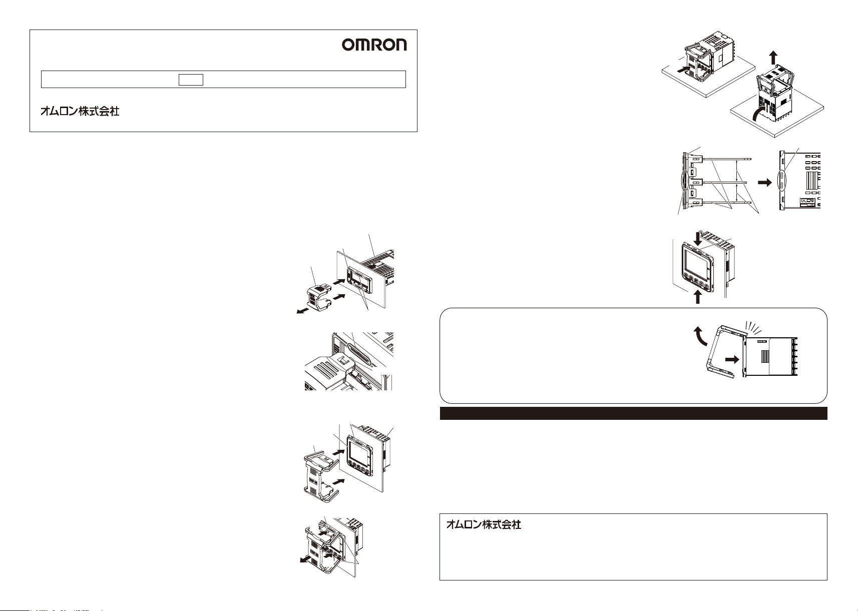
2 交換用の本体を用意します。
(1)製品をテーブルに水平に置き、ドローアウト治具をドローアウト治具
挿入穴(上下2箇所)に「カチッ」という音が するまでゆっくり水 平 に挿
(1)
入してくださ い 。
(図は形E5CC-D)
(2)製品を上向きの状態でテーブルに置き直します。
(3)リア ケ ー スを 手 で 押 さえながら、ゆっくりと垂直方向に本体を引き抜
いてください。製品を手に持った状態で水平に引き抜くと本体が落
下し、破損する可能性があります。
3 交換用の本体をリアケースに差し込みます。
【上面図】
シーリングゴム位 置
(1)本体をリアケースに差し込むときは、必ずシーリングゴムを装着した
基板を平行にしてシーリングゴムの位置がずれないように本体をリ
アケースに差し込んでください。
(2)上下のケースフックが確実に掛かるようにリアケースフック(上下2
箇所)を手で押えてください。正しく装 着しな いと防 水 性 を保つこと
ができない可能性があります。
また、本体をリアケースに挿入する際には、基板の電子部品をリア
ケースに接触させないでください。
ケースフック
(2)
(図は形E5CC-D)
(2)
ドローアウト治具挿入穴にフックが片側のみ掛かった場合の外し方
(形Y92F-55/Y92F-58/Y92F-59共通)
(1)ドローアウト治具を図に示す方向にゆっくりと引いてください。
(フックが掛かった箇所が逆の場合も同様です。)
ドローアウト治具がドローアウト挿入穴から外れたことを確認します。
(2)
(3)本体がリアケースから外れた場合は、本体をリアケースにゆっくり
水平に差し込んでください(図は形E5CC-D)。
上記手順に従わない場合、製品が破損する可能性があります。
(1)
(3)
ご承諾事項
当社商品は、一般工業製品向けの汎用品として設計製造されています。従いまして 、次に掲げる用途での使用を意図しておらず、お客様が当社商品をこれらの用
途に使用される際には、当社は当社商品に対して一切保証をいたしませ ん 。ただし、次に掲げる用途であっても当社の意図した特別な商品用途の場合や特別の
合意がある場合は除きます。
(a)高い安全性が必要とされ る 用 途(例:原子力制御設備、燃焼設備、航空・宇宙設備、鉄道設備、昇降設備、娯楽設備、医用機器、安全装置、その他生命・身
体に危険が及びうる用途)
(b)高い信頼性が必要な用途(例:ガス・水道・電 気等の供給システム、24時間連続運転システム、決済システムほか権利・財産を取扱う用途など)
(c)厳しい条件または環境での用途(例:屋外に設置する設備、化学的汚染を被る設備、電磁的妨害を被る設備、振動・衝撃を受ける設備など)
(d)カタログ等に記載のない条件や環境での用途
*(a)から(d)に記載されている他、本カタログ等記 載の商 品は自動車(二輪車含む。以下同じ)向けではありません。自動車に搭載する用途には利用しないで下さ
い。自動車搭載用商品については当社営業担当者にご相談ください 。
*上記は適合用途の条件の一部です。当社のベスト、総合カタログ、データシート等最新版のカタログ、マニュアルに記載の保証・免責事項の内容をよく読 ん でご
使用ください 。
●FAXやWebページでもお問い合わせいただけます。
FAX055-982-5051/www.fa.omron.co.jp
●その他のお問い合わせ
納期・価格・サンプル・仕様書は貴社のお取引先、
または貴社担当オムロン販売員にご相談ください 。
オムロン制御機器販売店やオムロン販売拠点は、
Webページでご案内しています。
お断りなく仕 様 などを変更 することがあります のでご 了 承ください 。
インダストリア ル オートメーション
ビジネスカンパニー
●製品に関するお問い合わせ先
お客様相談室
0120-919-066
携帯電話・PHS・IP電話などではご利用いただけ
ません ので 、下記の電話番号へおかけください 。
電話055-982-5015(通話料がかかります )
■営業時間:8:00 〜 21:00
■営業日:365日
(フリー通話)
(3)
(2)
(1)
基板
平行にして 、リアケースへ
差し込 んでください 。
リアケースフック
(2)
リアケースフック
 Loading...