

Page 1
Vision Sensor
FH/FHV Series
Vision System
User's manual for Communication Settings
FH-1£££/FH-1£££-££
FH-2£££/FH-2£££-££
FH-3£££/FH-3£££-££
FH-5£££/FH-5£££-££
FH-L£££/FH-L£££-££
FHV7£-£££££-C
FHV7£-£££££-S££/FHV7£-£££££-S££-££
FHV7£-£££££-H££/FHV7£-£££££-H££-££
Z342I-E3-14
Page 2

NOTE
• All rights reserved.
• No part of this publication may be reproduced, stored in a retrieval system, or transmitted, in any
form, or by any means, mechanical, electronic, photocopying, recording, or otherwise, without the
prior written permission of OMRON.
• No patent liability is assumed with respect to the use of the information contained herein. Moreover
because OMRON is constantly striving to improve its high-quality products, the information con-
tained in this manual is subject to change without notice. Every precaution has been taken in the
preparation of this manual. Nevertheless, OMRON assumes no responsibility for errors or omis-
sions.
Neither is any liability assumed for damages resulting from the use of the information contained in
this publication.
Trademarks
• Sysmac and SYSMAC are trademarks or registered trademarks of OMRON Corporation in Japan
and other countries for OMRON factory automation products.
• This software is based in part on the work of the Independent JPEG Group.
• Microsoft, Windows, Windows Vista, Excel, and Visual Basic are either registered trademarks or
trademarks of Microsoft Corporation in the United States and other countries.
• Intel, Core and Pentium are trademarks of Intel Corporation in the U.S. and/or other countries.
• EtherCAT® is registered trademark and patented technology, licensed by Beckhoff Automation
GmbH, Germany.
• ODVA, CIP, CompoNet, DeviceNet, and EtherNet/IP are trademarks of ODVA.
• The SD, SDHC, microSD, and microSDHC logos are trademarks of SD-3C, LLC.
,
• QR Code is a registered trademark of DENSO WA
VE INCORPORATED.
• MELSEC is a registered trademarks of Mitsubishi Electric Corporation.
Other company names and product names in this document are the trademarks or registered trade-
marks of their respective companies.
Copyrights
Microsoft product screen shots reprinted with permission from Microsoft Corporation.
Page 3

Introduction
Thank you for purchasing the FH/FHV Series.
This manual contains information that is necessary to use the FH/FHV Series.
Please read this manual and make sure you understand the functionality and performance of the
FH/FHV Series before you attempt to use it in a control system.
Keep this manual in a safe place where it will be available for reference during operation.
Intended Audience
This manual is intended for the following personnel, who must also have knowledge of electrical systems (an electrical engineer or the equivalent).
• Personnel in charge of introducing FA systems.
• Personnel in charge of designing FA systems.
• Personnel in charge of installing and maintaining FA systems.
• Personnel in charge of managing FA systems and facilities.
Introduction
Applicable Products
This manual covers the following products.
• FH-1£££
• FH-1£££-££
• FH-2£££
• FH-2£££-££
• FH-3£££
• FH-3£££-££
• FH-5£££
• FH-5£££-££
• FH-L£££
• FH-L£££-££
• FHV7£-££££
Part of the specifications and restrictions are given in other manuals. Refer to Relevant Manuals on
Relevant Manuals on page 2 and Related Manuals on page 17.
FH/FHV Series Vision System User's manual for Communication Settings (Z342-E1)
1
Page 4

Relevant Manuals
Relevant Manuals
The following table provides the relevant manuals for the FH/FHV Series.
Read all of the manuals that are relevant to your system configuration and application before you use
the FH/FHV Series.
Purpose of use
Basic information
FH/FHV Series Vision System
User's Manual
Hardware Setup Manual
FH Series Vision System
FHV Series Smart Camera
Setup Manual
Manual
FH/FHV Series Vision System
Processing Item Function
Reference Manual
FH Series Vision System
Macro Customize Functions
Programming Manual
FH/FHV Series Vision System
User’
s Manual for Communications Settings
FH/FHV Series Vision System
Operation Manual for Sysmac Studio
Overview of FH series
Overview of FHV7 series
Setup and Wiring
EtherCAT
EtherNet/IP
PROFINET
Ethernet
RS-232C
Parallel interface
Setup the communication setting of Sensor Controller
EtherCAT
EtherNet/IP
PROFINET
Ethernet
RS-232C
Parallel interface
Setup the Sensor Controller
EtherCAT
EtherNet/IP
PROFINET
Ethernet
RS-232C
Parallel interface
l l
l l
l l
l
l l l l
l
l l
2
FH/FHV Series Vision System User's manual for Communication Settings (Z342-E1)
Page 5

Purpose of use
Basic information
FH/FHV Series Vision System
User's Manual
Hardware Setup Manual
FH Series Vision System
FHV Series Smart Camera
Setup Manual
Relevant Manuals
Manual
FH/FHV Series Vision System
Processing Item Function
Reference Manual
FH Series Vision System
Macro Customize Functions
Programming Manual
FH/FHV Series Vision System
User’
s Manual for Communications Settings
FH/FHV Series Vision System
Operation Manual for Sysmac Studio
Create and Set the Scene
EtherCAT
EtherNet/IP
PROFINET
Ethernet
RS-232C
Parallel interface
Optimizing the Scene Flow
EtherCAT
EtherNet/IP
PROFINET
Ethernet
RS-232C
Parallel interface
Connecting the Controller
EtherCAT
EtherNet/IP
PROFINET
Ethernet
RS-232C
Parallel interface
Using Helpful Functions
EtherCAT
EtherNet/IP
PROFINET
Ethernet
RS-232C
Parallel interface
Troubleshooting and Problem Solving
l
l l
l l
l
l l l l
l
l
l
FH/FHV Series Vision System User's manual for Communication Settings (Z342-E1)
3
Page 6
4-9
4 Installation and Wiring
NJ-series CPU Unit Hardware User’s Manual (W500)
stinU gnitnuoM 3-4
4
stnenopmoC rellortnoC gnitcennoC 1-3-4
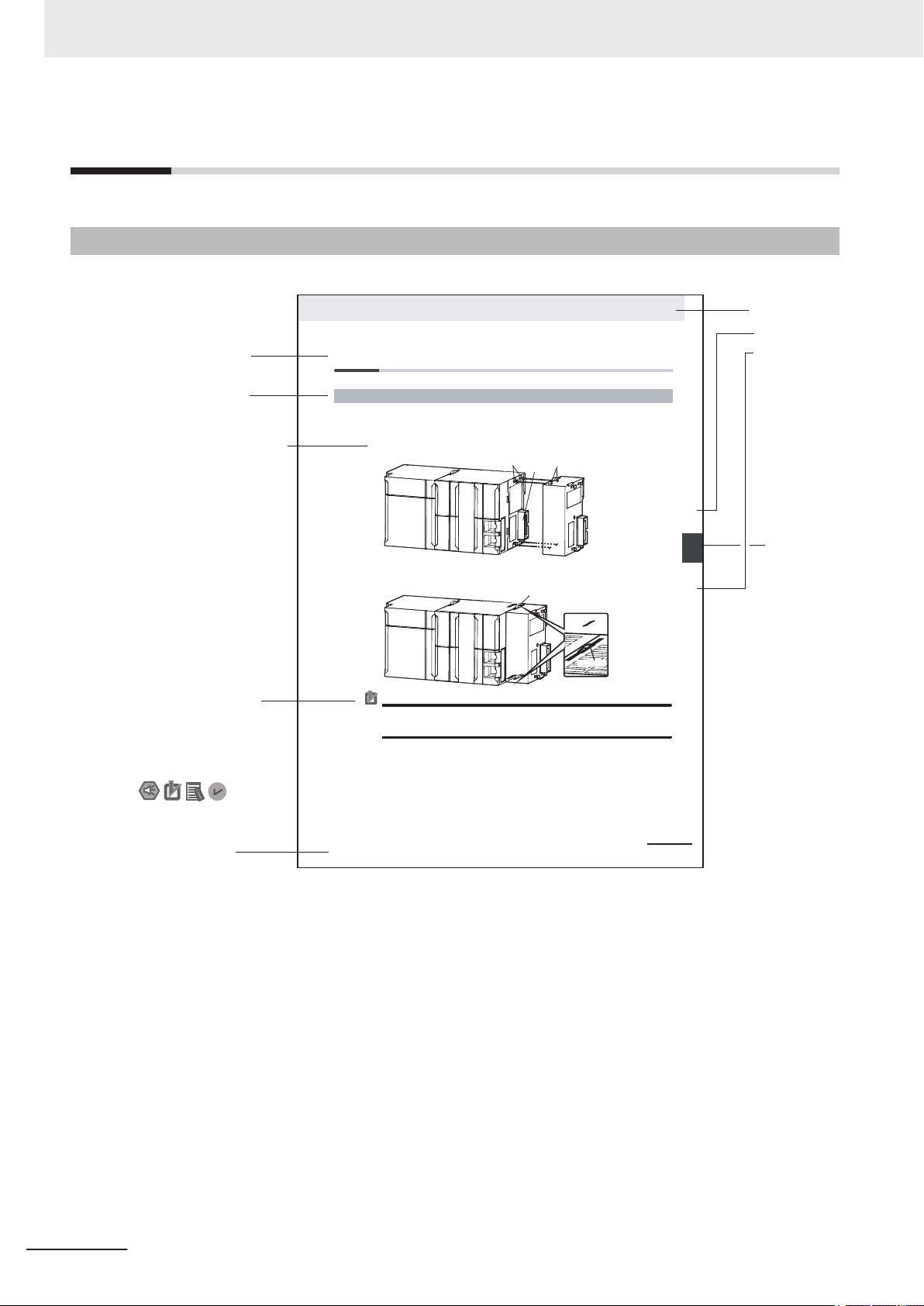
4-3 Mounting Units
The Units that make up an NJ-series Controller can be connected simply by pressing the Units together
and locking the sliders by moving them toward the back of the Units. The End Cover is connected in the
same way to the Unit on the far right side of the Controller.
1 Join the Units so that the connectors fit exactly.
2 The yellow sliders at the top and bottom of each Unit lock the Units together. Move the sliders
toward the back of the Units as shown below until they click into place.
Precautions for Correct UsePrecautions for Correct Use
4-3-1 Connecting Controller Components
Connector
Hook
Hook holes
Slider
Lock
Release
Move the sliders toward the back
until they lock into place.
Level 1 heading
Level 2 heading
Level 3 heading
Level 2 heading
A step in a procedure
Manual name
Special information
Level 3 heading
Page tab
Gives the current
headings.
Indicates a procedure.
Icons indicate
precautions, additional
information, or reference
information.
Gives the number
of the main section.
The sliders on the tops and bottoms of the Power Supply Unit, CPU Unit, I/O Units, Special I/O
Units, and CPU Bus Units must be completely locked (until they click into place) after connecting
the adjacent Unit connectors.
Manual Structure
Manual Structure
Page Structure
The following page structure is used in this manual.
Note This illustration is provided only as a sample. It may not literally appear in this manual.
4
FH/FHV Series Vision System User's manual for Communication Settings (Z342-E1)
Page 7

Special Information
Special information in this manual is classified as follows:
Precautions for Safe Use
Precautions on what to do and what not to do to ensure safe usage of the product.
Precautions for Correct Use
Precautions on what to do and what not to do to ensure proper operation and performance.
Additional Information
Additional information to read as required.
This information is provided to increase understanding or make operation easier.
Manual Structure
Conventions Used in This Manual
Use of Quotation Marks and Brackets
In this manual, menus and other items are indicated as follows.
Bold Menu Indicates the menu names or processing items shown in the menu bar.
Italic Item name Indicates the item names displayed on the screen.
FH/FHV Series Vision System User's manual for Communication Settings (Z342-E1)
5
Page 8

Manual Structure
6
FH/FHV Series Vision System User's manual for Communication Settings (Z342-E1)
Page 9
Sections in This Manual
1
2
A
I
1
2
A
I
Overview
Methods for Connecting and
Communicating with External Devices
Appendices
Index
Sections in This Manual
FH/FHV Series Vision System User's manual for Communication Settings (Z342-E1)
7
Page 10

CONTENTS
CONTENTS
Introduction .............................................................................................................. 1
Intended Audience...........................................................................................................................................1
Applicable Products
Relevant Manuals..................................................................................................... 2
Manual Structure...................................................................................................... 4
Page Structure.................................................................................................................................................4
Special Information .......................................................................................................................................... 5
Conventions Used in This Manual ................................................................................................................... 5
Terms and Conditions Agreement........................................................................ 11
Safety Precautions................................................................................................. 13
.........................................................................................................................................1
Precautions for Safe Use ...................................................................................... 14
Precautions for Correct Use ................................................................................. 15
Regulations and Standards .................................................................................. 16
Related Manuals..................................................................................................... 17
Revision History..................................................................................................... 19
Sections in This Manual .......................................................................................... 7
Section 1 Overview
1-1 Introduction ............................................................................................................................1-2
1-2 Confirming the System Configuration
1-2-1 System Configuration..................................................................................................................1-3
1-3 Communicating with an External Device.............................................................................1-4
1-3-1 Basic Control Operations of the Sensor Controller .....................................................................1-4
1-3-2 Communications between the Sensor Controller and an External Device..................................1-5
1-3-3 Control Methods for the Sensor Controller..................................................................................1-7
1-3-4 Communication Protocols for Communicating with the Sensor Controller..................................1-9
1-3-5 Saving Sensor Controller Data to an External Device ..............................................................1-11
1-4 Control Methods Using an External Device ......................................................................1-13
1-4-1 Control with Control Signals and Status Signals.......................................................................1-13
1-4-2 Command/Response Method ...................................................................................................1-16
1-4-3 Data Output after Measurements..............................................................................................1-17
1-5 Setting Procedures for Communications .......................................................................... 1-28
1-5-1 Communications Setup Procedures..........................................................................................1-28
1-5-2 Communications Protocols and Communications Modules ......................................................1-29
1-6 Differences in Specifications Based on the Communications Protocol ........................1-31
1-6-1 List of Supported Signals by Communications Protocol ...........................................................1-31
1-6-2 Restrictions when Using Different Communication Protocols Simultaneously..........................1-33
1-6-3 Restrictions in Communication Protocols by Operation Mode ..................................................1-33
1-6-4 Models being Compatible with Communication Protocol ..........................................................1-34
.................................................................................1-3
8
FH/FHV Series Vision System User's manual for Communication Settings (Z342-E1)
Page 11

CONTENTS
Section 2 Methods for Connecting and Communicating with Ex-
ternal Devices
2-1 EtherCAT Connections .......................................................................................................... 2-4
2-1-1 Introduction to EtherCA
2-1-2 Structure of CAN Application Protocol over EtherCAT (CoE) .....................................................2-7
2-1-3 EtherCAT Slave Information Files (ESI Files) .............................................................................2-8
2-1-4 Transitions of Communications States........................................................................................2-9
2-1-5 Process Data Objects (PDOs) ..................................................................................................2-10
2-1-6 Service Data Objects (SDOs) ...................................................................................................2-13
2-1-7 Communications between Master and Slaves for EtherCAT ...................................................2-14
2-1-8 Communication Method of FH Sensor Controller Connected by EtherCAT ..............................2-15
2-1-9 Communications Settings .........................................................................................................2-20
2-1-10 Communications Module Settings (Startup Settings)................................................................2-22
2-1-11 Communication Specifications Settings ....................................................................................2-23
2-1-12 Output Data Settings (Processing Item Registration) ...............................................................2-28
2-1-13 Setting Output Data (Numerical Values/Character Strings) ......................................................2-31
2-1-14 EtherCAT Network Configuration Settings ................................................................................2-37
2-1-15 Communication Test..................................................................................................................2-38
2-1-16 I/O Ports by Area (PDO Mapping) and Memory Allocation .......................................................2-39
2-1-17 I/O Signals.................................................................................................................................2-45
2-1-18 Measurement Results for which Output is Possible (Fieldbus Data Output) ............................2-49
2-1-19 Command List ...........................................................................................................................2-51
2-1-20 Measurement Trigger Input.......................................................................................................2-54
2-1-21 Command Response Processing..............................................................................................2-55
2-1-22 Data Output...............................................................................................................................2-57
2-1-23 Timing Chart..............................................................................................................................2-60
2-1-24 EtherCAT Troubleshooting ........................................................................................................2-64
2-1-25 Sysmac Error Status .................................................................................................................2-66
2-1-26 Sysmac Device Features ..........................................................................................................2-84
2-1-27 Object Dictionary.......................................................................................................................2-87
2-2 Communicating by PLC Link ............................................................................................ 2-126
2-2-1 Communications Processing Flow ..........................................................................................2-126
2-2-2 Communications Settings .......................................................................................................2-128
2-2-3 Communications Module Settings (Startup Settings)..............................................................2-129
2-2-4 Communication Specifications Settings ..................................................................................2-131
2-2-5 Output Data Settings (Processing Item Registration) .............................................................2-152
2-2-6 Setting Output Data (Numerical Values and Character Strings) .............................................2-157
2-2-7 Testing Communications .........................................................................................................2-163
2-2-8 Memory Allocation...................................................................................................................2-167
2-2-9 I/O Signals...............................................................................................................................2-171
2-2-10 Output Items............................................................................................................................2-174
2-2-11 Command List .........................................................................................................................2-175
2-2-12 Command Response Processing............................................................................................2-179
2-2-13 Data Output.............................................................................................................................2-182
2-2-14 Timing Chart............................................................................................................................2-184
2-2-15 PLC Link Troubleshooting.......................................................................................................2-187
2-3 Communicating by EtherNet/IP ........................................................................................2-190
2-3-1 Introduction to EtherNet/IP......................................................................................................2-190
2-3-2 Data Exchange with EtherNet/IP.............................................................................................2-191
2-3-3 EtherNet/IP Communications..................................................................................................2-194
2-3-4 Communications Processing Flow ..........................................................................................2-195
2-3-5 Communications Settings .......................................................................................................2-197
2-3-6 Communications Module Settings (Startup Settings)..............................................................2-198
2-3-7 Communication Specifications Settings ..................................................................................2-199
2-3-8 Setting Tag Data Link ..............................................................................................................2-206
2-3-9 Output Data Settings (Processing Item Registration) .............................................................2-211
2-3-10 Setting Output Data (Numerical Values and Character Strings) .............................................2-216
2-3-11 Testing Communications .........................................................................................................2-222
2-3-12 Memory Allocation...................................................................................................................2-224
2-3-13 I/O Signals...............................................................................................................................2-234
2-3-14 Output Items............................................................................................................................2-238
T.............................................................................................................2-4
FH/FHV Series Vision System User's manual for Communication Settings (Z342-E1)
9
Page 12

CONTENTS
2-4 Communicating by PROFINET .........................................................................................2-259
2-5 Non-procedure Communications ..................................................................................... 2-313
2-6 Parallel Communications ..................................................................................................2-351
2-3-15 Command List .........................................................................................................................2-239
2-3-16 Command Response Processing
2-3-17 Data Output.............................................................................................................................2-247
2-3-18 Timing Chart............................................................................................................................2-249
2-3-19 Communicating with the Sensor Controller using EtherNet/IP Message Communications ....2-252
2-3-20 Example for Command Settings .............................................................................................2-255
2-3-21 EtherNet/IP Troubleshooting...................................................................................................2-256
2-4-1 Overview of PROFINET ..........................................................................................................2-259
2-4-2 PROFINET Communications ..................................................................................................2-262
2-4-3 Communications Processing Flow ..........................................................................................2-263
2-4-4 Communications Settings .......................................................................................................2-265
2-4-5 Communications Module Settings (Startup Settings)..............................................................2-266
2-4-6 Communication Specifications Settings ..................................................................................2-267
2-4-7 IO Data Communication Settings............................................................................................2-273
2-4-8 Output Data Settings (Processing Item Registration) .............................................................2-275
2-4-9 Setting Output Data (Numerical Values and Character Strings) .............................................2-279
2-4-10 Testing Communications .........................................................................................................2-285
2-4-11 Memory Allocation...................................................................................................................2-288
2-4-12 I/O Signals...............................................................................................................................2-294
2-4-13 Output Items............................................................................................................................2-298
2-4-14 Command List .........................................................................................................................2-299
2-4-15 Command Response Processing............................................................................................2-302
2-4-16 Data Output.............................................................................................................................2-305
2-4-17 Timing Chart............................................................................................................................2-307
2-4-18 PROFINET Troubleshooting ...................................................................................................2-310
2-5-1 Communications Processing Flow ..........................................................................................2-313
2-5-2 Communications Setup Procedures .......................................................................................2-314
2-5-3 Communications Module Settings (Startup Settings)..............................................................2-314
2-5-4 Communications Specifications Settings ................................................................................2-316
2-5-5 Output Data Settings (Processing Item Registration) ............................................................2-321
2-5-6 Output Data Settings (Numerical Values/Character Strings) ..................................................2-327
2-5-7 Testing Communications .........................................................................................................2-335
2-5-8 Output Items............................................................................................................................2-338
2-5-9 Command Formats .................................................................................................................2-340
2-5-10 Command List .........................................................................................................................2-342
2-5-11 Output Format .........................................................................................................................2-346
2-5-12 Non-procedure Communications Troubleshooting..................................................................2-348
2-6-1 Communications Processing Flow .........................................................................................2-351
2-6-2 Communications Setup Procedures .......................................................................................2-353
2-6-3 Communications Module Settings (Startup Settings)..............................................................2-354
2-6-4 Communications Specifications Settings ...............................................................................2-355
2-6-5 Output Data Settings (Processing Item Registration) .............................................................2-364
2-6-6 Output Data Settings (Numerical value/Judgment) ................................................................2-370
2-6-7 Testing Communications .........................................................................................................2-376
2-6-8 I/O Signals...............................................................................................................................2-378
2-6-9 Output Items............................................................................................................................2-389
2-6-10 Command Formats .................................................................................................................2-391
2-6-11 Time Charts.............................................................................................................................2-395
2-6-12 Parallel Troubleshooting..........................................................................................................2-409
............................................................................................2-243
Appendices
A-1 Command Control................................................................................................................. A-2
A-1-1 Parameter Notation Examples for Command Control
A-1-2 Details of Commands Used in EtherCAT Communications ....................................................... A-6
A-1-3 Command List ............................................................................................................................ A-7
A-1-4 Command Details for PLC Link, EtherNet/IP, EtherCAT, and PROFINET ............................... A-15
A-1-5 Non-procedure Command Details............................................................................................ A-85
10
................................................................ A-2
FH/FHV Series Vision System User's manual for Communication Settings (Z342-E1)
Page 13

Terms and Conditions Agreement
Terms and Conditions Agreement
Warranty, Limitations of Liability
• Warranties
Exclusive Warranty:
Omron's exclusive warranty is that the Products will be free from defects in materials and workmanship for a period of twelve months from the date of sale by Omron (or such other period expressed
in writing by Omron). Omron disclaims all other warranties, express or implied.
Limitations:
OMRON MAKES NO WARRANTY OR REPRESENTATION, EXPRESS OR IMPLIED, ABOUT
NONINFRINGEMENT, MERCHANTABILITY OR FITNESS FOR A PARTICULAR PURPOSE OF
THE PRODUCTS. BUYER ACKNOWLEDGES THAT IT ALONE HAS DETERMINED THAT THE
PRODUCTS WILL SUITABLY MEET THE REQUIREMENTS OF THEIR INTENDED USE.
Omron further disclaims all warranties and responsibility of any type for claims or expenses based
on infringement by the Products or otherwise of any intellectual property right.
Buyer Remedy:
Omron’s sole obligation hereunder shall be, at Omron’s election, to (i) replace (in the form originally
shipped with Buyer responsible for labor charges for removal or replacement thereof) the non-complying Product, (ii) repair the non-complying Product, or (iii) repay or credit Buyer an amount equal
to the purchase price of the non-complying Product; provided that in no event shall Omron be responsible for warranty, repair, indemnity or any other claims or expenses regarding the Products unless Omron’s analysis confirms that the Products were properly handled, stored, installed and maintained and not subject to contamination, abuse, misuse or inappropriate modification. Return of any
Products by Buyer must be approved in writing by Omron before shipment. Omron Companies shall
not be liable for the suitability or unsuitability or the results from the use of Products in combination
with any electrical or electronic components, circuits, system assemblies or any other materials or
substances or environments. Any advice, recommendations or information given orally or in writing,
are not to be construed as an amendment or addition to the above warranty.
See http://www.omron.com/global/ or contact your Omron representative for published information.
• Limitation on Liability; Etc
OMRON COMPANIES SHALL NOT BE LIABLE FOR SPECIAL, INDIRECT, INCIDENTAL, OR
CONSEQUENTIAL DAMAGES, LOSS OF PROFITS OR PRODUCTION OR COMMERCIAL LOSS
IN ANY WAY CONNECTED WITH THE PRODUCTS, WHETHER SUCH CLAIM IS BASED IN
CONTRACT, WARRANTY, NEGLIGENCE OR STRICT LIABILITY.
Further, in no event shall liability of Omron Companies exceed the individual price of the Product on
which liability is asserted.
Application Considerations Warranties
• Suitablity of Use
Omron Companies shall not be responsible for conformity with any standards, codes or regulations
which apply to the combination of the Product in the Buyer’s application or use of the Product. At
Buyer’s request, Omron will provide applicable third party certification documents identifying ratings
FH/FHV Series Vision System User's manual for Communication Settings (Z342-E1)
11
Page 14

Terms and Conditions Agreement
and limitations of use which apply to the Product. This information by itself is not sufficient for a
complete determination of the suitability of the Product in combination with the end product, machine, system, or other application or use.
Buyer shall be solely responsible for determining appropriateness of the particular Product with respect to Buyer’
es.
NEVER USE THE PRODUCT FOR AN APPLICATION INVOLVING SERIOUS RISK TO LIFE OR
PROPERTY OR IN LARGE QUANTITIES WITHOUT ENSURING THAT THE SYSTEM AS A
WHOLE HAS BEEN DESIGNED TO ADDRESS THE RISKS, AND THAT THE OMRON PRODUCT(S) IS PROPERLY RATED AND INSTALLED FOR THE INTENDED USE WITHIN THE OVERALL EQUIPMENT OR SYSTEM.
• Programmable Products
Omron Companies shall not be responsible for the user’s programming of a programmable Product,
or any consequence thereof.
Disclaimers
• Performance Data
Data presented in Omron Company websites, catalogs and other materials is provided as a guide
for the user in determining suitability and does not constitute a warranty. It may represent the result
of Omron’s test conditions, and the user must correlate it to actual application requirements. Actual
performance is subject to the Omron’s Warranty and Limitations of Liability.
• Change in Specifications
Product specifications and accessories may be changed at any time based on improvements and
other reasons. It is our practice to change part numbers when published ratings or features are
changed, or when significant construction changes are made. However, some specifications of the
Product may be changed without any notice. When in doubt, special part numbers may be assigned
to fix or establish key specifications for your application. Please consult with your Omron’s representative at any time to confirm actual specifications of purchased Product.
• Errors and Omissions
Information presented by Omron Companies has been checked and is believed to be accurate;
however, no responsibility is assumed for clerical, typographical or proofreading errors or omissions.
s application, product or system. Buyer shall take application responsibility in all cas-
12
FH/FHV Series Vision System User's manual for Communication Settings (Z342-E1)
Page 15

Safety Precautions
For details of Safety Precautions, refer to Safety Precautions in the Vision System FH/FHV Series
User's Manual (Cat. No. Z365).
Safety Precautions
FH/FHV Series Vision System User's manual for Communication Settings (Z342-E1)
13
Page 16

Precautions for Safe Use
Precautions for Safe Use
For details of Precautions for Safe Use, refer to Precautions for Safe Use in the Vision System
FH/FHV Series User's Manual (Cat. No. Z365).
14
FH/FHV Series Vision System User's manual for Communication Settings (Z342-E1)
Page 17

Precautions for Correct Use
For details of Precautions for Correct Use, refer to Precautions for Correct Use in the Vision System
FH/FHV Series User's Manual (Cat. No. Z365).
Precautions for Correct Use
FH/FHV Series Vision System User's manual for Communication Settings (Z342-E1)
15
Page 18

Regulations and Standards
Regulations and Standards
For details of Regulations and Standards, refer to Regulations and Standards in the Vision System
FH/FHV Series User's Manual (Cat. No. Z365).
16
FH/FHV Series Vision System User's manual for Communication Settings (Z342-E1)
Page 19

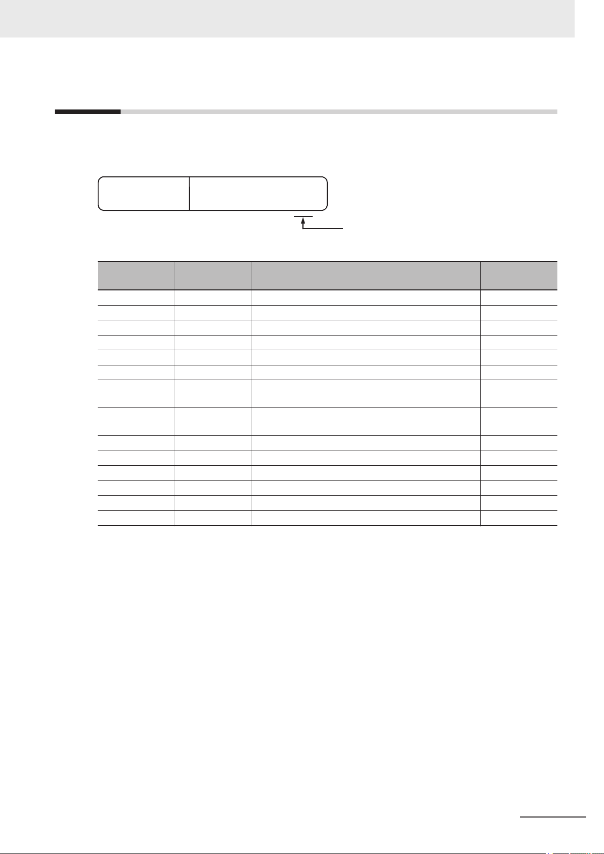
Related Manuals
The followings are the manuals related to this manual. Use these manuals for reference.
Name of Manual Cat. No.. Model Purpose Contents
Vision System
FH Instruction Sheet
Vision System
FH Instruction Sheet
Vision System
FH-L Instruction Sheet
Smart Camera
FHV Instruction Sheet
Smart Camera
Lighting Module
TM Instruction Sheet
FHV-L
Smart Camera Lens Module
FHV-LEM-S Instruction
Sheet
Smart Camera High-Speed
Lens Module
FHV-LEM-H Instruction
Sheet
FHV Series
Smart Camera
Setup Manual
9608337-2
3102269-4
9606631-1
3129404-0
3129276-4
3128622-5
3129408-2
Z408
FH-1£££
FH-1£££-££
FH-3£££
FH-3£££-££
FH-2£££
FH-2£££-££
FH-5£££
FH-5£££-££
FH-L£££
FH-L£££-££
FHV7£-£££££-C
FHV-LTM££
-LEM-S££
FHV
-LEM-H££
FHV
FHV7£-£££££-C
FHV7£-£££££-S££
FHV7£-£££££-S££-£
£
FHV7£-£££££-H££
FHV7£-£££££-H££-£
£
To confirm the safety
and usage precautions of the V
System FH series
Sensor Controller
To confirm the safety
and usage precautions of the V
System FH series
Sensor Controller
To confirm the safety
and usage precautions of the Vision
System FH-Lite series Sensor Control-
.
ler
To confirm the safety
and usage precautions of the Smart
Camera FHV7 series.
To confirm the safety
and usage precautions of the Smart
camera lighting module FHV-LTM.
To confirm the safety
and usage precautions of the Smart
camera lens module
FHV-LEM-S.
To confirm the safety
and usage precautions of the Smart
camera high-speed
lens module FHVLEM-H.
When User want to
know about the hardware specifications
or to setup the Smart
camera FHV series.
ision
.
ision
.
Describes the definitions of basic
terms, meaning of signal words, and
precautions for correct use of FH
series in the manual.
To confirm the safety and usage precautions of the Vision System FH
series Sensor Controller.
Describes the definitions of basic
terms, meaning of signal words, and
precautions for correct use of FH-L
series in the manual.
Describes the definitions of basic
terms, the meaning of signal words,
and precautions for correct use of
FHV7 series in the manual.
Describes the definitions of basic
terms, the meaning of signal words,
and precautions for correct use of
the lighting module FHV-LTM in the
manual.
Describes the definitions of basic
terms, the meaning of signal words,
and precautions for correct use of
the lens module FHV-LEM-S.
Describes the definitions of basic
terms, the meaning of signal words,
and precautions for correct use of
the high-speed lens module FHVLEM-H.
Describes FHV series specifications,
dimensions, part names, I/O information, installation information, and
wiring information.
Related Manuals
FH/FHV Series Vision System User's manual for Communication Settings (Z342-E1)
17
Page 20

Related Manuals
Name of Manual Cat. No.. Model Purpose Contents
Vision System
FH/FHV Series
User's Manual
Vision System
FH/FHV series
Processing Item Function
Reference Manual
Vision System
FH/FHV Series
User's manual for Communications Settings
Vision System
FH series
Hardware Setup Manual
ision System
V
FH series
Macro Customize Functions Programming Manual
Vision System
FH/FHV Series
Operation Manual
for Sysmac Studio
Z365
Z341 When User confirm
Z342 When User confirm
Z366
Z367 When User operate
Z343
FH-1£££
FH-1£££-££
FH-2£££
FH-2£££-££
FH-3£££
FH-3£££-££
FH-5£££
FH-5£££-££
FH-L£££
FH-L£££-££
FHV7£-£££££-C
FHV7£-£££££-S££
FHV7£-£££££-S££-£
£
FHV7£-£££££-H££
FHV7£-£££££-H££-£
£
FH-1£££
FH-1£££-££
FH-2£££
FH-2£££-££
FH-3£££
FH-3£££-££
FH-5£££
FH-5£££-££
FH-L£££
FH-L£££-££
FH-1£££
FH-1£££-££
FH-2£££
FH-2£££-££
FH-3£££
FH-3£££-££
FH-5£££
FH-5£££-££
FHV7£-£££££-C
FHV7£-£££££-S££
FHV7£-£££££-S££-£
£
FHV7£-£££££-H££
FHV7£-£££££-H££-£
£
When User want to
know about the
FH/FHV series.
the details of each
processing items at
the create the measurement flow or operate it.
the setting of communication functions.
When User want to
know about the
Hard-ware specifications or to setup the
Sensor Controller of
ision System
the V
FH series.
or programming using Macro Customize
functions.
When User connect
to NJ/NX series via
T communi-
EtherCA
cation.
Describes the soft functions, setup,
and operations to use FH/FHV series/
Describes the software functions,
settings, and operations for using
FH/FHV series.
Describes the functions, settings,
and communications methods for
communication between FH/FHV
series and PLCs.
The following communications protocol are described.
Parallel, PLC Link, EtherNet/IP
EtherCA
Describes FH series specifications,
dimensions, part names, I/O information, installation information, and
wiring information.
Describes the functions, settings,
and operations for using Macro Customize function of the FH series.
Describes the operating procedures
for setting up and operating FH/FHV
series Vision Sensors from the Sysmac Studio FH/FHV T
,
T, and Non-procedure.
ools.
18
FH/FHV Series Vision System User's manual for Communication Settings (Z342-E1)
Page 21
Revision History
Revision code
Cat. No. Z342-E1-14
A manual revision code appears as a suffix to the catalog number on the front and back covers of the
manual.
Revision History
Rev. Code Rev. Date Revision Contents
01 Jul. 2013 First edition Ver. 5.00
02 Aug. 2013 Additions for software version upgrade Ver. 5.10
03 Sep. 2013 Additions for software version upgrade Ver. 5.12
04 Jan. 2014 Additions for software version upgrade Ver. 5.20
05 Jun. 2014 Additions for software version upgrade Ver. 5.30
06 Oc. 2015 Additions for software version upgrade Ver. 5.50
07 Apr. 2016 Additions for software revision upgrade and descrip-
tion of FH-L series
08 Mar. 2017 Corrected mistakes.
Additions for software revision upgrade
09 Jun. 2017 Additions for software version upgrade Ver. 5.72
10 Jul. 2018 Additions for software version upgrade Ver. 6.10
11 Nov. 2018 Additions for software version upgrade Ver. 6.20
12 Jul. 2019 Additions for software version upgrade Ver. 6.30
13 Nov. 2019 Corrected mistakes. Ver. 6.30
14 Jun. 2020 Corrected mistakes. Ver. 6.40
Software Ver-
sion
Ver. 5.60
Ver. 5.71
FH/FHV Series Vision System User's manual for Communication Settings (Z342-E1)
19
Page 22

Revision History
20
FH/FHV Series Vision System User's manual for Communication Settings (Z342-E1)
Page 23

Overview
This section describes communication specifications to be used for communications
between FH/FHV and an external device, and the Sensor Controller control methods.
1
1
1-1 Introduction
1-2 Confirming the System Configuration .........................................................1-3
1-2-1 System Configuration ..................................................................................... 1-3
1-3 Communicating with an External Device..................................................... 1-4
1-3-1 Basic Control Operations of the Sensor Controller......................................... 1-4
1-3-2 Communications between the Sensor Controller and an External Device ..... 1-5
1-3-3 Control Methods for the Sensor Controller ..................................................... 1-7
1-3-4 Communication Protocols for Communicating with the Sensor Controller ..... 1-9
1-3-5 Saving Sensor Controller Data to an External Device ...................................1-11
1-4 Control Methods Using an External Device............................................... 1-13
1-4-1 Control with Control Signals and Status Signals .......................................... 1-13
1-4-2 Command/Response Method ....................................................................... 1-16
1-4-3 Data Output after Measurements ................................................................. 1-17
1-5 Setting Procedures for Communications ..................................................1-28
1-5-1 Communications Setup Procedures ............................................................. 1-28
1-5-2 Communications Protocols and Communications Modules.......................... 1-29
1-6 Differences in Specifications Based on the Communications Pro-
tocol................................................................................................................ 1-31
1-6-1 List of Supported Signals by Communications Protocol ............................... 1-31
1-6-2 Restrictions when Using Different Communication Protocols Simulta-
1-6-3 Restrictions in Communication Protocols by Operation Mode...................... 1-33
1-6-4 Models being Compatible with Communication Protocol.............................. 1-34
.................................................................................................... 1-2
neously .......................................................................................................... 1-33
FH/FHV Series Vision System User's manual for Communication Settings (Z342-E1)
1-1
Page 24

1 Overview
1-1
Introduction
This section describes a basic overview of the Sensor Controller control methods and the communication specifications, which is required when the FH/FHV series communicate with an external device.
Confirming the System Configuration
This section describes the external device configuration that is required to perform measurement processing
with the FH/FHV.
For details, refer to
Communicating with an External Device
This section describes the basic operations of the Sensor Controller, and the communication specifications between the Sensor Controller and an external device.
For Basic Flow of Communications and Signals, refer to 1-3-1 Basic Control Operations of the Sensor Control-
on page
ler
1-4
• Process from Starting Measurements at the Sensor Controller to Data Output:
For details, refer to 1-3-2 Communications between the Sensor Controller and an External Device on page
1-5.
• Sensor Controller Control Methods (Control Signals, Commands, etc.)
For details, refer to 1-3-3 Control Methods for the Sensor Controller on page 1-7.
• Types of Communication Protocols for Communicating with the Sensor Controller
For details, refer to 1-3-4 Communication Protocols for Communicating with the Sensor Controller on page
1-9.
• Moving Data between the Sensor Controller and an External Device
For details, refer to 1-3-5 Saving Sensor Controller Data to an External Device on page 1-11.
Control Methods Using an External Device
This section describes the methods that you can use to control the Sensor Controller from an external device.
• Control with Control Signals and Status Signals
For details, refer to 1-4-1 Control with Control Signals and Status Signals on page 1-13.
• Command/Response Method
For details, refer to
• Data Output after Measurements
For details, refer to 1-4-3 Data Output after Measurements on page 1-17.
Setting Procedures for Communications
This section describes the procedures that are required to set up communications before starting communications between the Sensor Controller and an external device.
For details, refer to 1-5-1 Communications Setup Procedures on page 1-28.
ferences in Specifications Based on the Communications Protocol
Dif
This section describes the types and differences of communication protocols that are used for communications
with the Sensor Controller
For details, refer to
1-2 Confirming the System Configuration on page 1-3.
↓
↓
1-4-2 Command/Response Method on page 1-16.
↓
↓
.
1-5-2 Communications Protocols and Communications Modules on page 1-29.
1-2
FH/FHV Series Vision System User's manual for Communication Settings (Z342-E1)
Page 25
Sensor Controller
External device (e.g, PLC)
Camera
1 Overview
1-2 Confirming the System Con-
1-2
1-2-1
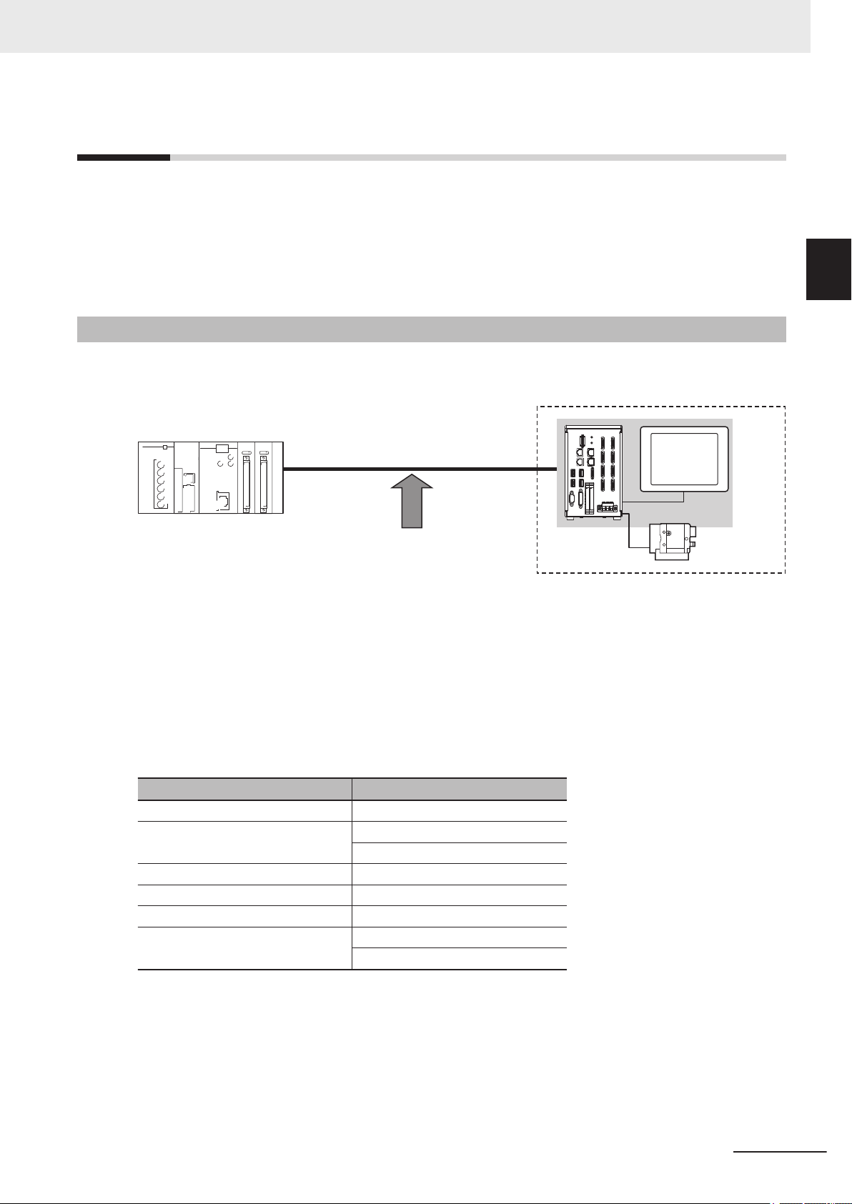
Confirming the System Configuration
The FH/FHV are Vision Systems that perform measurement processing through the Sensor Controller
on measurement objects imaged by a Camera.
In a system configuration connected to an external device such as a PLC or a PC (personal computer), measurement commands can be received from and measurement results can be output to the external device.
System Configuration
An overview of the FH/FHV series system configuration is shown below.
figuration
1
1-2-1 System Configuration
The Sensor Controller and an external device (PLC, etc.) are connected with a communication cable
and communicate with each other using various communication protocols. For details of various com-
e
munication protocols, refer to S
Devices on page 2-1.
An LCD monitor (BOX type only) for operation and monitoring and a camera are connected to the
Sensor Controller unit.
For details, refer to Vision System FH Series User's Manual (Cat. No. Z365), Smart Camera FHV
Series Setup Manual (Cat. No. Z408), and the Instruction Manual provided with each individual device.
Communications Protocol Communication Cable
Parallel Parallel I/O cable
PLC Link
EtherNet/IP Ethernet cable
EtherCAT Ethernet cable
PROFINET Ethernet cable
Non-procedure
ction 2 Methods for Connecting and Communicating with External
Ethernet cable
RS-232C cable
Ethernet cable
RS-232C cable
FH/FHV Series Vision System User's manual for Communication Settings (Z342-E1)
1-3
Page 26
Trigger sensor
PLC
External device
External device
PLC
The measurement
results are output.
• Status signals
• Overall judgement
• Measured values
• Character output
Sensor Controller
Measurement triggers
and other control
commands are input.
1 Overview
1-3
1-3-1
Communicating with an External Device
This section describes the communication specifications, control methods in communications, and settings required before starting communications with an external device.
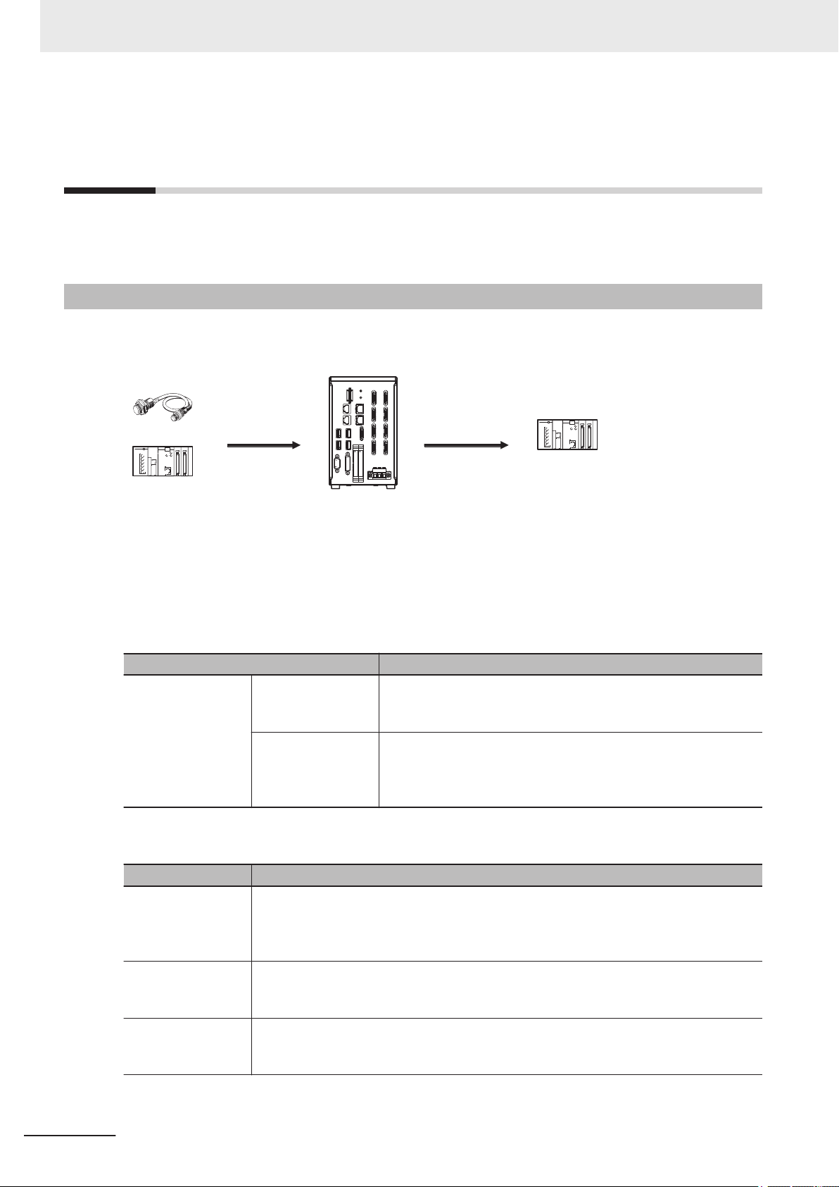
Basic Control Operations of the Sensor Controller
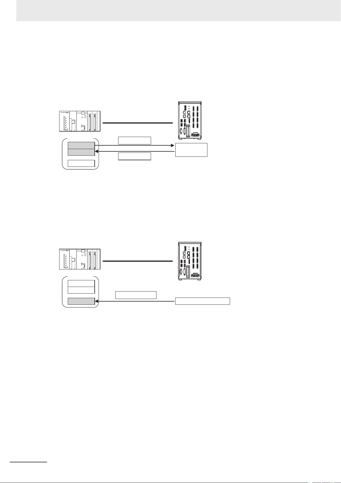
The following figure shows basic communications, and the flow of signals and data, between an external device and the Sensor Controller.
1-4
The following methods are used to exchange commands and data, between an external device and
the Sensor Controller.
From an external device to the Sensor Controller
Type Description
Control signals
(Input signal)
Control commands
Communications
command input
From the Sensor Controller to an external device
Type Description
When the Sensor Controller recognizes a control signal or communication command in-
Status signals
Overall judgment
Measured values
put and starts measurement processing, it reports its status to the external device using
status signals such as a BUSY signal. For details, refer to Control Signals and Status
Signals on page 1-13.
NG is output whenever there is one or more NGs in the judgment results for multiple
processing items. It can be output using the OR signal or the TJG output parameter. For
details, refer to
The measured values for processing items are output. The items to be output need to be
previously registered to the output data (data 0 to 7) using processing items for output.
For details, refer to Settings Required for Data Output on page 1-21.
FH/FHV Series Vision System User's manual for Communication Settings (Z342-E1)
A measurement is performed when a measurement trigger (i.e.,
STEP signal: ON) is input. For information of control signals, refer
to Control Signals and Status Signals on page 1-13.
Y
ou can send commands to perform measurements, switch scene
groups, or perform other tasks. The communication commands
depend on the communication protocol used. For details, refer to
the section for each communication protocol.
Control Signals and Status Signals on page 1-13.
Page 27
Type Description
PLC or other external device
Camera Input
Search
Output Unit
Measurement
flow
Sensor Controller
Communications
Module
Communications processing
Example: Starting a
measurement, etc.
Response
Data output request
(DSA signal)*1
Result Completion signal (GATE signal)*1
(1) Command
Communications
processing
(2) The data at this
point is output to the
Communications
Module.
An Output Unit processing item is required to
perform data output. (Multiple Output Unit items
can be used.)
(3) Data
output
Character output
1 Overview
This is valid in PLC Link and Non-procedure communications protocols.
You can output character strings and numbers read by processing items such as Character Inspection, Barcode, or 2D Code. Y
a measurement is performed. For details, refer to Items that can be Output as Output
Data on page 1-19.
ou can also use commands to acquire them after
1-3 Communicating with an Ex-
ternal Device
1-3-2
Additional Information
You can also use the FTP server to obtain logged image files and logged data files saved in the
FH/FHV (including external storage) from a FTP client such as web browser.
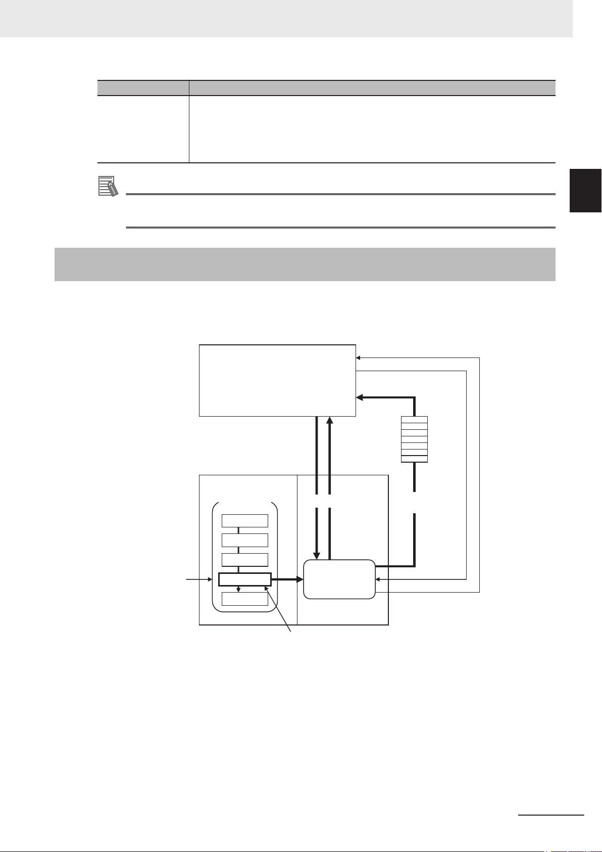
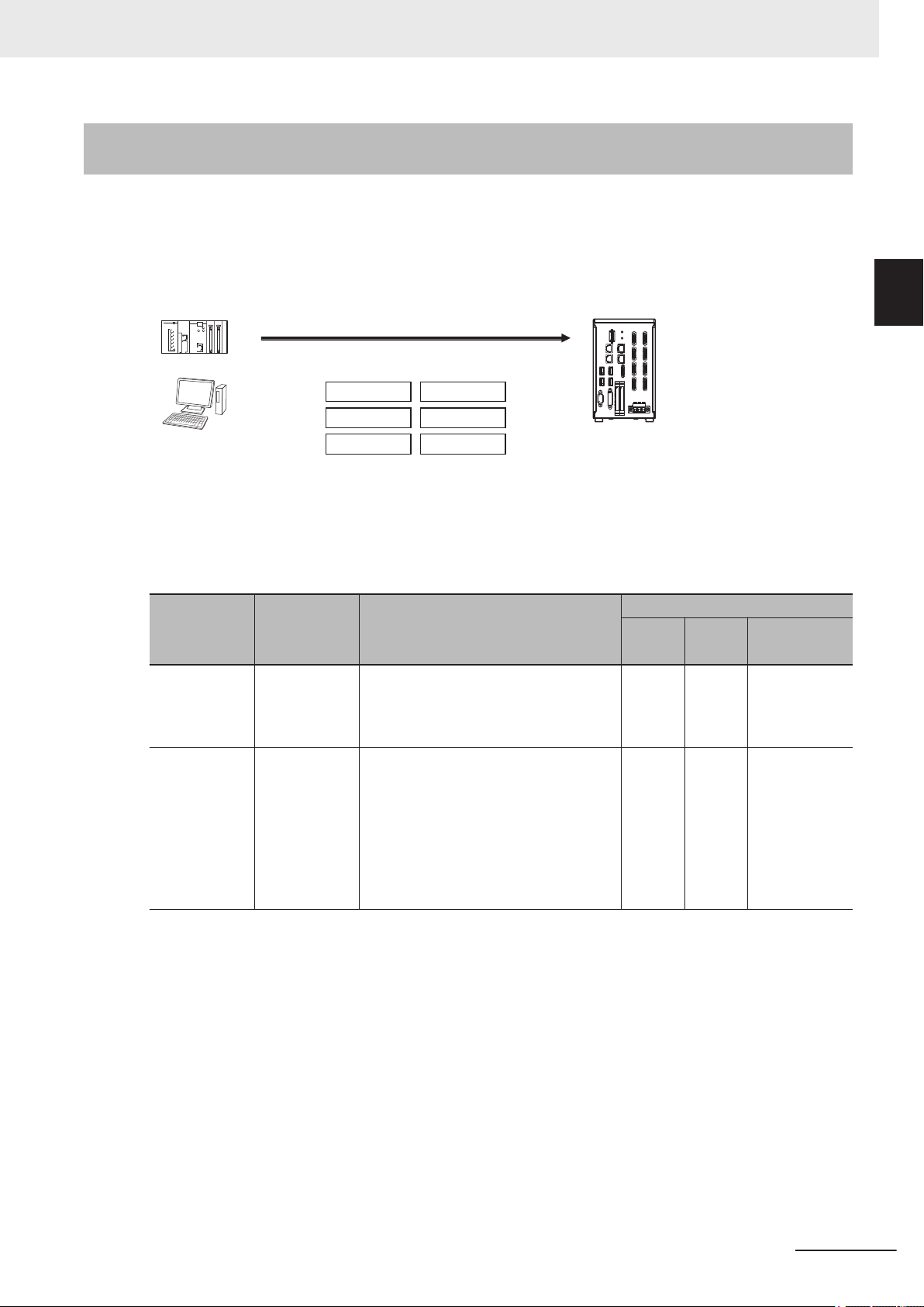
Communications between the Sensor Controller and an External
Device
Communications between the Sensor Controller and an external device are performed as shown below.
Here, describe how to start measurement with a communication command and to output data.
1
1-3-2 Communications between the Sensor Controller and an External Device
FH/FHV Series Vision System User's manual for Communication Settings (Z342-E1)
(1) When the Sensor Controller receives a command from an external device such as a PLC, it performs the
(2) The measured data is output via the Communication module by the Output Unit (an abbreviation for
(3)
command and returns a response.
Results Output Unit) placed in the measurement flow.
The measurement data is output when the Output Unit is performed and not when the measurement is
completed.
*2
1-5
Page 28

1 Overview
*1 When output control is set to handshaking (data output is controlled by the DSA and GATE signals).
*2
For details, refer to Control Signals and Status Signals on page 1-13.
When handshaking is performed in the output control, the measurement data is held in the Communication module until a data output request (DSA signal) is received from the external device.
For details, refer to Data Output Control with Handshaking on page 1-25.
Precautions for Correct Use
To output data, you must place an Output Unit processing item in the measurement flow.
You can place multiple Output Unit processing items in the measurement flow.
For details, refer to
Settings Required for Data Output on page 1-21.
1-6
FH/FHV Series Vision System User's manual for Communication Settings (Z342-E1)
Page 29
Trigger sensor
External device
Status signal
Control signal
Sensor Controller
1 Overview
1-3 Communicating with an Ex-
1-3-3
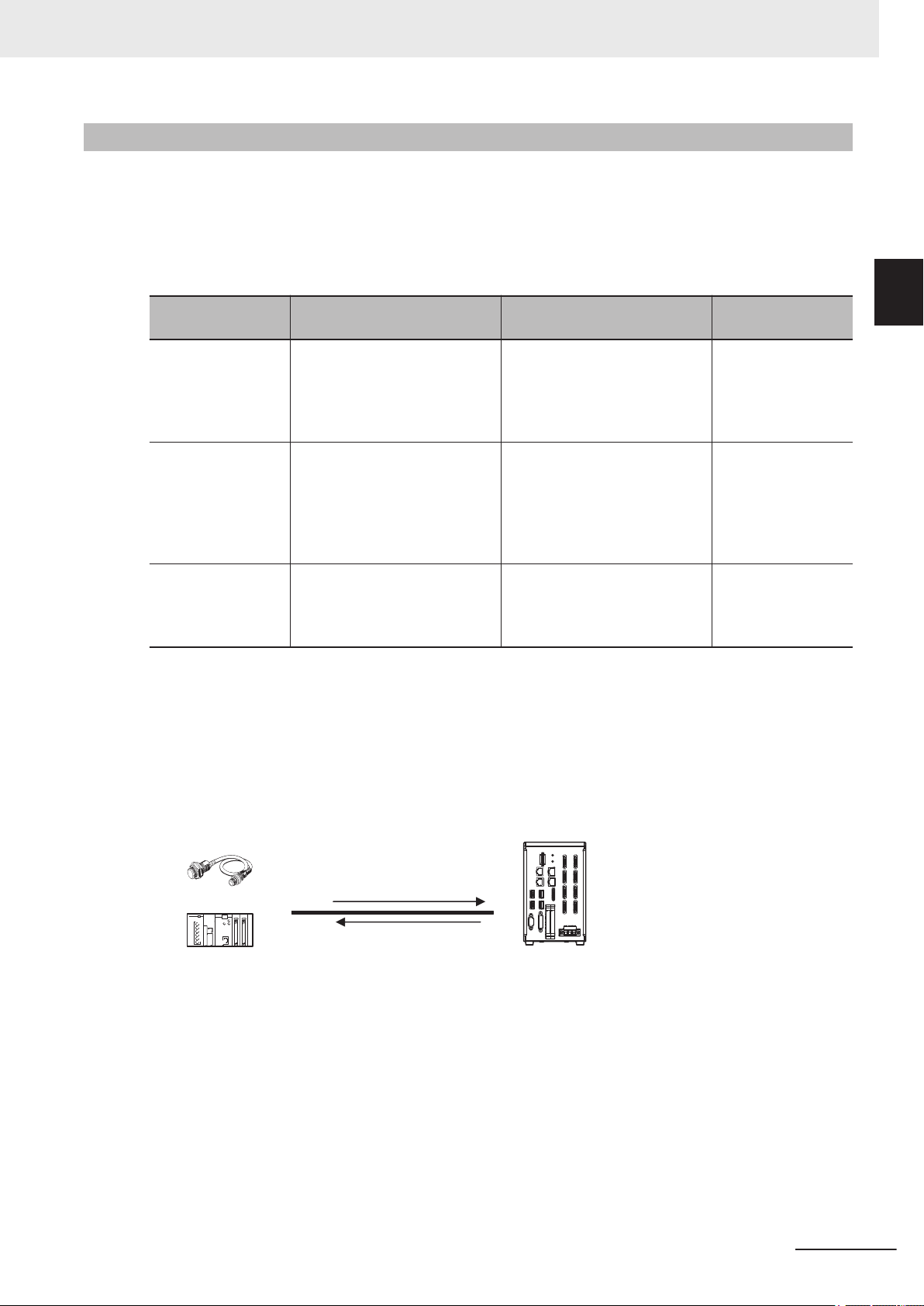
Control Methods for the Sensor Controller
There are three methods below to control the Sensor Controller with an external device such as a
PLC.
For details of each control method, refer to their corresponding section.
Control Methods
Method Overview Trigger type and area
Operation is controlled by the
Control signals and
status signals
Control with commands and responses
Data output after
measurement
ON/OFF status of the Measurement Trigger Signal (STEP)
and Command Request Bit
(EXE).
Operation is controlled by sending control commands. The results performed by the commands can be checked with responses from the Sensor Controller.
After measurement was performed, the previously specified
measurement data is automatically output.
ON/OFF status of the control
signals and status signals
The control command code is
stored in the I/O memory of the
PLC and then the Request bit is
turned ON.
Not required (Automatically output after measurement)
Signal and area to
be used
Control signals and
status signals
PLC I/O memory
(Command and Response Areas)
PLC I/O memory
(Data Output Area)
ternal Device
1
1-3-3 Control Methods for the Sensor Controller
1. Control with Control Signals and Status Signals (Refer to 1-4-1 Control with Control Signals
and Status Signals on page 1-13.)
Control and status check for the Sensor Controller is performed with the ON/OFF status of the control and status signals.
This method is best suited for basic operations such as measurement triggers or for checking the
operating status of the Sensor Controller.
FH/FHV Series Vision System User's manual for Communication Settings (Z342-E1)
1-7
Page 30
External device
I/O memory
Sensor Controller
Command Area
Response Area
(1) Command
(3) Response
Output Area
(2) Command
execution
External device
I/O memory
Sensor Controller
Command Area
Response Area
(2) Measurement data
Output Area
(1) Measurement processing
1 Overview
2. Control with Commands and Responses (Refer to 1-4-2 Command/Response Method on
3. Data Output after Measurement (Refer to 1-4-3 Data Output after Measurements on page
page 1-16.)
Control is performed by storing a control command and the response to it to the PLC’s I/O memory
This method is best suited to send multiple commands to the Sensor Controller without using exclusive communication instructions for a PLC.
1-17.)
After measurement was performed, the previously specified measurement data is automatically
output to the PLC’
s specified I/O memory.
This allows you to output measurement results from the Sensor Controller to the PLC automatically
without sending data requests from the PLC.
.
1-8
FH/FHV Series Vision System User's manual for Communication Settings (Z342-E1)
Page 31
PLC
Computer
EtherNet/IP
EtherCAT
Non-procedure
Parallel
PLC Link
Sensor Controller
Control can be performed through different communications protocols.
PROFINET
1 Overview
1-3 Communicating with an Ex-
1-3-4
Communication Protocols for Communicating with the Sensor
Controller
The Sensor Controller can be controlled using various communication protocols by an external device
such as a PLC or a PC.
The communication protocols to control the Sensor Controller by an external device are described be-
.
low
● Applicable Communications Protocols
The communication protocols and summary for each communication method available in the Sensor
Controller are below.
OK: Supported, - : Not supported
ternal Device
1
1-3-4 Communication Protocols for Communicating with the Sensor Controller
Communica-
tion method
Contract
input
Frame
transmission
Communica-
tion
protocol
Parallel
Non-procedure
Overview
Using a combination of ON and OFF
signals of multiple physical contacts exchanges data between an external device and the Sensor Controller.
Without using any specific communication protocol, command frames are sent
to the Sensor Controller and response
frames are received from it.
By sending and receiving data in ASCII
or binary formats, data is communicated
between an external device such as a
PLC or a PC and the Sensor Controller.
Communication Cable Type
Parallel
I/O
OK
-
Ether-
net
- -
OK OK
RS-232C/
422
*2
FH/FHV Series Vision System User's manual for Communication Settings (Z342-E1)
1-9
Page 32

1 Overview
Communica-
tion method
Communica-
tion
protocol
Overview
Parallel
This is a communication protocol for the
OMRON Vision System.
Areas for control signals, Command,
PLC Link
Response, and measurement data are
assigned in the PLC’
s I/O memory, and
data is communicated between the PLC
and the Vision System by sharing them
cyclically.
This is an open communication protocol.
Tag data links are used to communicate
with the Sensor Controller
.
Structure variables corresponding to the
EtherNet/IP
control signals, command data and response data, and measurement data
are created on the PLC. Those variables are used as tags to input and output data via the tag data links to exchange data between the PLC and the
Data
sharing
Sensor Controller.
This is an open communication proto-
*1
col.
Areas for control signals, Command,
PROFINET
Response, and measurement data are
assigned in the PLC’s I/O memory
, and
data is exchanged between the PLC
and the Vision System by sharing the
data via IO data CR.
This is an open communication protocol.
PDO (process data object) communications are used to communicate with the
Sensor Controller.
I/O ports corresponding to the control
EtherCAT
signals, command data, response data,
and measurement data are prepared in
advance, and the variables assigned to
the I/O ports are used to input and output data via PDO communications to
exchange data between the PLC and
the Sensor Controller
.
*1. When a CJ series PLC is connected, specify each area in the I/O memory.
*2. FH-1000/2000/3000/5000, and FHV series equip RS-232C only.
Communication Cable Type
RS-232C/
*2
422
I/O
Ether-
net
- OK OK
- OK -
- OK -
- OK -
1-10
FH/FHV Series Vision System User's manual for Communication Settings (Z342-E1)
Page 33

Computer Sensor Controller
Ethernet
Saved directly.
• Logged images
• Logged data
Shared computer folder (the
shared folder settings must
be set on the computer)
The Sensor Controller is set
up to save to the shared
folder on the computer.
Computer
Browser
(FTP client)
Sensor Controller (FTP server)
Ethernet
Access via FTP
RAM disk
Images files moved to the computer.
Image files
This enables you to move logged images off of the Sensor Controller’s RAM disk before it becomes full.
1 Overview
1-3 Communicating with an Ex-
1-3-5
Saving Sensor Controller Data to an External Device
In addition to sending and receiving data via a communication protocol, you can also save data in the
Sensor Controller to an external device using the methods described below
For details, refer to the V
ision System FH/FHV Series User's Manual (Cat. No. Z365)..
Connecting the FH/FHV as an External Drive
In addition to the Sensor Controller's built-in RAM disk, you can directly save various types of data
such as scene data, scene group data, logged data, and logged images to the external media below.
• For external storage, refer to Using External Storage Devices in the Vision System FH/FHV Series
User’s Manual (Cat. No. Z365).
Data can be saved directly to a USB memory stick or SD Memory Card inserted into the slot on the
Sensor Controller.
• For network drive, refer to the Shared folder on a computer connected to the network in the Vision
System FH/FHV Series User’s Manual (Cat. No. Z365).
You can save data directly to a shared folder on a computer connected via Ethernet.
.
ternal Device
1
1-3-5 Saving Sensor Controller Data to an External Device
• For data transfer (FTP server), refer to the Saving Data to an External Device in the Vision System
FH/FHV Series User
’s Manual (Cat. No. Z365).
You can move logged image files and other data saved in the Sensor Controller’s RAM disk or a
USB memory stick to a computer via Ethernet.
The computer needs to have an FTP client function to access the Sensor Controller of the FH/FHV
series. The computer cannot be accessed directly from the Sensor Controller.
FH/FHV Series Vision System User's manual for Communication Settings (Z342-E1)
1-11
Page 34

Sensor
Controller
Ethernet
Computer (FH/FZ5 Tool)
Hub
Sensor
Controller
Sensor
Controller
Operate/monitor
1 Overview
• For remote operation over a network, refer to the Remotely Operating the Controller (Remote
Operation) in the Vision System FH/FHV Series User
’s Manual (Cat. No. Z365).
If more than one Sensor Controller is connected via Ethernet, a computer (FZ tool) connected to the
same Ethernet network can operate and monitor all the Sensor Controllers at once.
1-12
FH/FHV Series Vision System User's manual for Communication Settings (Z342-E1)
Page 35

Trigger sensor Sensor Controller
(1) Measurement trigger input
(STEP signal: ON).
Control signal
(2) Command received.
(BUSY signal turned ON.)
(3) Judgement results are output.
(OR signal turned ON.)
Status signals
External device
1 Overview
1-4 Control Methods Using an
1-4
1-4-1
Control Methods Using an External
Device
This section describes how to control the Sensor Controller from an external device such as a PLC.
Control with Control Signals and Status Signals
Control and status check for the Sensor Controller is performed with the ON and OFF status of the
control and status signals.
A PLC inputs measurement triggers or other commands as control signals.
The operating status of the Sensor Controller, judgment results, and other status information can be
checked with status signals output from the Sensor Controller.
External Device
1
1-4-1 Control with Control Signals and Status Signals
(1) The external device turns the STEP signal ON to input a measurement trigger to the Sensor Controller.
(2) When the Sensor Controller identifies that the STEP signal is turned ON, it outputs the BUSY signal to
notify the external device and starts measurement.
(3) When the Sensor Controller completes the measurement, it outputs the judgment results on the OR signal
to notify the external device.
Control Signals and Status Signals
The signal types that are input and output to the Sensor Controller as control and status signals are
described below.
Input Signals (PLC to Sensor Controller)
l
Signal Name Function
EXE
Command Request
rigger Measure Bit
T
STEP Measure Bit
DSA
(Used only for handshaking output control)
Result Set Request
ERCLR
Error Clear
Control Command Execution Signal
Data Output Request
Signal
Error Clear Bit
This is turned ON when the PLC will issue a command to the FH/FHV
This is turned ON when measurement will be performed.
This is turned ON when measurement will be performed.
During handshaking, the user (PLC) uses this signal
to request to output data output results performed in
the measurement flow to external from the Sensor
Controller of the FH/FHV series.
This is turned ON when the ERR signal from the
Sensor Controller will be cleared.
.
FH/FHV Series Vision System User's manual for Communication Settings (Z342-E1)
1-13
Page 36

1 Overview
l
Signal Name Function
XEXE
Flow Command Request
DI (DI0 to DI7) Command Input Signals
ENCTRIG
Flow Command
Request Bit
Encoder Trigger Input
(Phase A, B, Z)
This is turned ON when a command will be performed while PLC Link, Fieldbus, or parallel flow
control is performed.
These are used to input commands from a parallel
interface.
This is the encoder input signal.
This signal is only available when the encoder trigger
will be used.
Output Signals (Sensor Controller to PLC)
Signal Name Function
This signal indicates that new requests cannot be
accepted because an external input such as a command is currently handled.
BUSY Busy Signal
FLG
Command Completion
TE
GA
Result Notification
READY
Trigger Ready
OR
Total Judgment
DI (DO0 to DO15) Data Output Signals
XFLG
Flow Command Completion
XBUSY
Flow Command Busy
XWAIT
Flow Command W
Trigger ACK
Command Ready
ait
Control Command Completion Signal
Data Output Completion
Signal
Camera Image
Input Enabled Signal
Overall Judgment Output
Signal
Flow Command
Completion Bit
Measurement Command
Busy Bit
Measurement Command
W
ait Bit
Trigger Signal Acknowledged Bit
Command Execution
Ready Bit
“ON” of this signal does not mean that a command is
currently performed. To check whether a command
is being executed, check the Command Completion
(FLG) signal.
The Sensor Controller of the FH/FHV series uses
this signal to inform the user (PLC) that a command
has been completed.
This signal informs the user (PLC) of the timing to
load output data.
“ON” of this signal indicates that the Sensor Control-
ler is outputting the data.
This signal indicates that the STEP (Measurement
T
rigger) signal or the T
When the multi-input function is used, following
STEP signal or Trigger signal is accepted only when
this signal is “ON”.
This signal notifies the overall judgment results.
These signals are used to output parallel data and
parallel judgment through a parallel interface.
This signal indicates that a command performed
while PLC Link or Fieldbus flow control is being performed has been completed.
This signal indicates that a command input while
PLC Link or Fieldbus flow control is being performed
is in execution.
This signal indicates that a command input can be
accepted while PLC Link or Fieldbus flow control is
being performed.
This signal indicates that the Sensor Controller of the
FH/FHV series has accepted a T
This signal indicates that a control command is executable.
*1
rigger signal can be input.
rigger signal.
*2
*3
1-14
FH/FHV Series Vision System User's manual for Communication Settings (Z342-E1)
Page 37

1 Overview
Signal Name Function
ERR
Error Status
RUN
Run Mode
ACK
SHTOUT
STGOUT Strobe Trigger Output This is the trigger signal for the strobe.
*1. This signal is linked to the Output Unit processing items in the measurement flow.
This has no linkage relation with the BUSY signal. Also, this has no linkage relation with the OR signal in
the parallel communication protocol. Note that the operation is different when PLC Link is used. For details, refer to
*2. This signal is always OFF during display of a through image.
When you use a camera with lighting controller, based on its type and connecting conditions, the time
required for the READY or T
it.
For details, refer to Camera Image Input FH, Camera Image Input HDR, or Camera Image Input FHV in
the Vision System FH/FHV Series User's Manual (Cat. No. Z365).
*3. The OR signal is output only when the Output option is selected in the Adjustment window.
2-2 Communicating by PLC Link on page 2-126.
Error Signal
Measurement Mode Signal
Command Completion
Flag
Exposure Completion
Signal
rigger Ready signal to turn OFF may increase in comparison with not using
This signal indicates that the FH/FHV detects the following errors.
• Camera connection error
• Battery error
• Fan error
• System error
• Communications timeout
• STEP input during measurement
The ERR signal does not turn OFF even after the error is eliminated. The signal turns OFF only when the
error status is cleared by a control command.
For details, refer to Error Messages and
T
roubleshooting in the
User's Manual (Cat. No. Z365)..
This is a notification signal indicating the Sensor
Controller of the FH/FHV series is in Run mode (In a
measurement capable state with RUN signal output
checked in the Layout settings for the currently displayed line).
This signal indicates that the DI command execution
has been completed.
This signal indicates that Camera exposure has
been completed.
Vision System FH/FHV Series
1-4 Control Methods Using an
External Device
1
1-4-1 Control with Control Signals and Status Signals
FH/FHV Series Vision System User's manual for Communication Settings (Z342-E1)
1-15
Page 38

DI7 DI6 DI4 DI3 DI2 DI1 DI0
Execution
Command
Command information
DI5
(1) Command Area
(5) Response Area
(2) Command
(4) Response
PLC
CPU Unit
I/O memory
(communications areas)
• Switch Scene Number
• Single Measurement, etc.
OK, etc.
(3) Command is processed.
Sensor Controller
1 Overview
1-4-2
Command/Response Method
● Parallel
Commands are input to the Sensor Controller by turning the DI signals (DI0 through DI7) ON and OFF
Since there is no direct response for these commands, so check the ACK signal whether or not a command was accepted.
The command code is input with signals DI0 through DI6, and the command is performed by turning
DI7 ON.
● PLC Link, EtherNet/IP, EtherCAT, or PROFINET
By storing control commands from the PLC to the Sensor Controller and responses from the Sensor
Controller to the PLC into the PLC’s I/O memory
changed. This enables you to control the Sensor Controller using commands such as single measurement and scene switch without any sequence control such as issuing communication commands from
the PLC.
Memory Areas Used by the Command/Response Method
, command and response control signals are ex-
.
Command
Area
Response
Areas
You write the control commands to execute for the Sensor Controller to this area.
You read the performed results of the control commands written in the Command Area from this
area.
Flow of Communications between the PLC and the Sensor Controller
(1) The PLC (the user) writes a control command to a specified PLC’s I/O memory area (the Command Area).
(2) The PLC (the user) then turns the EXE bit ON to send the control command to the Sensor Controller.
(3) The Sensor Controller perfoms the received control command.
(4) The Sensor Controller returns a response to the PLC after the control command was performed.
(5) The PLC (the user) stores the response in a specified PLC’s I/O memory area (the Response Area).
The communication commands depend on the communication protocol used.
For details, refer to A-1-3 Command List on page A-7.
1-16
FH/FHV Series Vision System User's manual for Communication Settings (Z342-E1)
Page 39

Data
Output Area
• Specified data is automatically output.
• Output characters
(2) Data
CPU Unit
PLC
I/O memory
(communications areas)
Sensor Controlle
r
Measurement
execution
(1)
1 Overview
1-4 Control Methods Using an
1-4-3
Additional Information
Command-driven character string output is not supported when using EtherNet/IP tag data link
communication, EtherCAT
, or PROFINET.
To output character strings, use commands equivalent to Non-procedure communication in the
EtherNet/IP message communication.
For details, refer to 2-3-19 Communicating with the Sensor Controller using EtherNet/IP Mes-
sage Communications on page 2-252
● Non-procedure Communications
Communication commands are sent to the Sensor Controller through sequence control in the PLC. An
external device and the Sensor Controller communicate through non-procedure (normal) communications.
Data Output after Measurements
Just after a Single Measurement or Start Continuous Measurement command is executed, the Sensor
Controller automatically outputs the data associated with the measurement specified in advance as
output items to the PLC. This allows you to easily pass measurement results data from the processing
items to the PLC. Y
receive the data (i.e., when handshaking is enabled).
The output destination for data depends on the protocol that is used to communicate between the external device and the Sensor Controller
ou can also choose to output only when the PLC meets the conditions required to
, as described below.
External Device
1
1-4-3 Data Output after Measurements
● PLC Link, EtherNet/IP, EtherCAT, or PROFINET
The output data is automatically output to the PLC’s specified I/O memory below.
Area of Memory Used for Data Output after Measurements:
Data output area
After measurement performed, the output data associated with the measurement is
written to this area by the Sensor Controller.
Flow of Communications between the PLC and the Sensor Controller:
The data to output after measurement performed and the PLC I/O memory area (Data Output Area) to
store that data need to be specified in advance. For details, refer to Settings Required for Data Output
on page 1-21.
FH/FHV Series Vision System User's manual for Communication Settings (Z342-E1)
Measurement is performed.
(1)
(2) After the measurement was performed, the specified measurement data is stored in the Data Output Area
in the PLC.
1-17
Page 40

Search measurement
results output.
Processing
order
Measurement started.
0.Camera Image Input
1.Search
2.Data Output
Communications
Module
Measurement flow
Sensor Controller
Measurement executed.
Processing started
(BUSY).
Single Measurement
command
The results for
measurements for
1. Search are output.
1 Overview
● Parallel
The data is output to the PLC signal lines via DO signals (DO0 to DO15).
● Non-procedure Communications
The data is output to the PLC reception buffer through non-procedure (normal) communications.
Outputting the Measurement Data
The measurement data is output to the external device via the Communications Module by the processing unit for data output (hereafter, Output Unit) placed in the measurement flow
Therefore, to output measurement data, you must place an Output Unit in the measurement flow in
advance.
The measurement data is output when the Output Unit is performed and not when the measurement
has been completed.
.
You can output character strings read by processing items such as Character Inspection, Barcode, or
2D Code. (Available only for PLC Link and Non-procedure protocols)
Character strings are output simultaneously when the processing item is performed.
1-18
FH/FHV Series Vision System User's manual for Communication Settings (Z342-E1)
Page 41
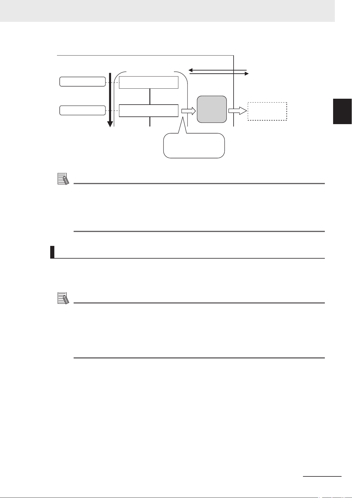
Processing
order
Measurement started.
0.Camera Image Input
1.Character Inspection
Communications
Module
Measurement flow
Sensor Controller
Measurement processed.
Processing started
(BUSY).
Single Measurement
command
Characters are output
at the same time that
the characters are read.
Read charac-
ters are output.
Additional Information
1 Overview
1-4 Control Methods Using an
External Device
1
1-4-3 Data Output after Measurements
Command-driven character string output is not supported when using EtherNet/IP tag data link
communication, EtherCAT
, or PROFINET.
To output character strings, use commands equivalent to Non-procedure communication in the
EtherNet/IP message communication.
For details, refer to 2-3-19 Communicating with the Sensor Controller using EtherNet/IP Mes-
sage Communications on page 2-252
Items that can be Output as Output Data
● Measurement Data
You can output at once up to eight items (32 bytes) with performing one Output Unit.
Additional Information
• If you need to output nine or more data items, set more than one Output Unit processing unit
in the measurement flow.
For details, refer to
• The number of data items that can be output by one Output Unit can be increased by chang-
ing a setting when using PLC Link or EtherCAT communications, as shown below.
- PLC Link: 256 max. (1,024 bytes max.)
- EtherCAT: 64 max. (256 bytes max.)
Outputting Multiple Measurement Data Items on page 1-23
The following items can be output.
• Judgment result
•
• Results calculated based on the values of the measured parameters
• Judgment results for expression results (Parallel Judgment Output)
● Character Output (Available only for PLC Link and Non-procedure Protocols)
You can output character strings read by processing items such as Character Inspection.
The maximum number of output characters are as follows.
• Character Inspection: 32 characters
• Barcode: 1,024 characters
• 2DCode: 652 characters
FH/FHV Series Vision System User's manual for Communication Settings (Z342-E1)
Measured parameters (correlation values, reference coordinates, etc.)
1-19
Page 42

1 Overview
• 2DCode II: 652 characters
• OCR: 128 characters (32 characters x 4 lines)
NULL (\0) is attached at the end of the read string to be output.
The processing items supporting character strings output are listed below
• Character Inspection
• Barcode
• 2DCode
• 2DCode II
• OCR
For details of the character output format, refer to each processing item description in the Vision
System FH/FHV Series Processing Items Reference Manual (Cat. No. Z341).
Additional Information
Command-driven character string output is not supported when using EtherNet/IP tag data link
communication, EtherCAT
To output character strings, use commands equivalent to Non-procedure communication in the
EtherNet/IP message communication.
For details, refer to 2-3-19 Communicating with the Sensor Controller using EtherNet/IP Mes-
sage Communications on page 2-252
, or PROFINET.
.
1-20
FH/FHV Series Vision System User's manual for Communication Settings (Z342-E1)
Page 43
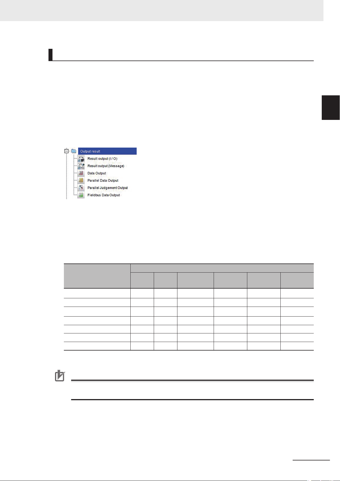
1 Overview
1-4 Control Methods Using an
Settings Required for Data Output
Use the following procedures to set up Output Unit for data output.
● Measurement Data
1. Place the data output processing unit(s) in the processing flow.
Place the processing unit for data output in the measurement flow.
Processing Units That Serve as Output Units:
On the processing item tree in the Flow Editor window
serve as Output Units.
Output Unit Selection:
Select the Output Units with the following combination according to a communication protocol to be
used.
For details of communication protocols, refer to 1-3-4 Communication Protocols for Communicat-
ing with the Sensor Controller on page 1-9.
, the processing items under Output result
OK: Data can be output, - : Data cannot be output.
External Device
1
1-4-3 Data Output after Measurements
Communication Protocol
Output unit
Result Output (I/O)
Result Output (Message) - - - - - OK
Result Output (Parallel I/O)
Parallel Data Output OK - - - - -
Parallel Judgment Output OK - - - - -
Serial Data Output - OK - - - OK
Fieldbus Data Output - - OK OK OK -
*1. Except message communications
Parallel
- OK
- OK
PLC
Link
EtherNet/IP EtherCAT PROFINET
OK
OK
*1
*1
OK OK -
OK OK -
procedure
Precautions for Correct Use
When Non-procedure UDP is used to output data of Result output (Message), the Sensor Controller outputs the data to only the device whose command was accepted in the end.
2. Set the items to output
Set the items to output as output data in the Output Units placed in the measurement flow
.
For the procedures to set output items in the Output Units, refer to the description for each communication protocol.
Non-
FH/FHV Series Vision System User's manual for Communication Settings (Z342-E1)
1-21
Page 44

1 Overview
● Character Output (Available only for PLC Link and Non-procedure Protocols)
Perform the character output settings for processing items to read output characters such as Character Inspection.
Since the above processing items perform the character output operation, it does not need to set Output Units in the measurement flow. For the settings to output characters, refer to the description for
each processing item in the V
No. Z341).
• Character Inspection
• Barcode
• 2DCode
• 2DCode II
• OCR
ision System FH/FHV Series Processing Items Reference Manual (Cat.
Additional Information
Command-driven character string output is not supported when using EtherNet/IP tag data link
communication, EtherCAT
To output character strings, use commands equivalent to Non-procedure communication in the
EtherNet/IP message communication.
For details, refer to 2-3-19 Communicating with the Sensor Controller using EtherNet/IP Mes-
sage Communications on page 2-252
, or PROFINET.
1-22
FH/FHV Series Vision System User's manual for Communication Settings (Z342-E1)
Page 45

Processing
order
Measurement started.
Search measurement
results output.
0.Camera Image Input
1.Search
4.Data Output
Communications
Module
Measurement flow
Sensor Controller PLC
Command
Area
I/O memory
Response
Area
Output Area
2.Data Output
3.Position Compensation
The data that is output
first is overwritten by the
second data output
Position compensa-
tion values output.
1 Overview
1-4 Control Methods Using an
Outputting Multiple Measurement Data Items
● Using Multiple Output Units for Data Output
You can register more than one Output Unit in the measurement flow.
If you want to output dif
put more than nine different data items, you must register multiple Output Units in the measurement
flow.
Although data output is performed for each Output Unit placed in the measurement flow, the output
destination for the data is the same PLC’s I/O memory area (Data Output Area).
Therefore, the first output data is overwritten by the following output data if you do nothing. When you
want to save all the output data, take one of the following means.
ferent types of data during measurement flow processing, or if you want to out-
External Device
1
1-4-3 Data Output after Measurements
FH/FHV Series Vision System User's manual for Communication Settings (Z342-E1)
● Outputting Data with Result Output (I/O) or Result Output (Message) Processing Unit
The “Result Output (I/O)” or “Result Output (Message)” processing item can output nine or more items
by only one processing item.
For details, refer to Result Output (I/O) or
Result Output (Message) in the Vision System FH/FHV
Series Processing Items Reference Manual (Cat. No. Z341).
1-23
Page 46

Processing
order
Measurement started.
0.Camera Image Input FH
1.Search
N+1. Result output (I/O)
Communications
Module
Measurement flow
S
ensor Controller PLC
Command
Area
I/O memory
Response
Area
Output Area
2. Advanced filter
N. -------------
Output the results of
Search or
Advanced filter
1 Overview
Offsets (Available only for PLC Link Communication Protocol):
When you use multiple Output Units to output data, you can offset the write destination of the output
data for each Output Unit.
Set the
Registration) on page 2-152.
Controlling Data Output with Handshaking:
When handshaking is used to control data output, the timing of outputting the data is controlled by I/O
signals. Therefore, each time that data is output, read and move the data to a different part in the
PLC’s I/O memory. For details, refer to Data Output Control with Handshaking on page 1-25.
The following two types of Output Units can be used via parallel communications:
Offset for the Data Output. For details, refer to 2-2-5 Output Data Settings (Processing Item
Additional Information
For ASCII data output through Non-procedure communications, you can append a record separator after each output data item. (The default is the delimiter.)
Output unit Output data
Parallel Data Output The measurement data is output. Up to eight items can be output.
The judgment results are output. Up to 16 judgment results can be output. The fol-
Parallel Judgment Output
lowing two types of judgment results can be output.
• Judgment results for specified processing items.
• Judgment results of arbitrary judgment conditions set for specified item values
1-24
Parallel Data Output and Parallel Judgment Output Units are output in the order they are processed in
the measurement flow.
FH/FHV Series Vision System User's manual for Communication Settings (Z342-E1)
Page 47

16 bits
Parallel data output
PLC
0. Measurement data 0
7. Measurement data 7
Reception
buffer
D
ata output order
Measurement
data 7
Measurement
data 0
GATE
signal
DO0 to DO15
signals
ON
OFF
1 Overview
● Outputting Multiple Items with Parallel Data Output
The items set for output data numbers 0 through 7 via parallel data output are output to the PLC’s reception buf
put, the GATE signal turns ON.
In that time, the first data item output to the PLC’s reception buffer (data 0) is overwritten with the following output data item (data 1).
Therefore, the data output to the PLC’s reception buffer needs to be moved to the PLC’s memory each
time the GATE signal turns ON.
fer in ascending order, one data item at a time (16-bit units). Each time a data item is out-
*1
1-4 Control Methods Using an
External Device
1
1-4-3 Data Output after Measurements
*1: The operation of the DSA signal depends on whether Handshaking for output control is enabled.
For details, refer toData Output Control with Handshaking on page 1-25.
Data Output Control with Handshaking
The timing for data output can be controlled through the DSA and GATE signals.
As the timing for transferring output data can be controlled, it is useful when output data from multiple
Output Units is received.
● Requirements for Using Data Output Control with Handshaking
When controlling data output, set the output control method to Handshaking in the communication protocol settings.
For details, refer to Communications Specifications Setting for each communication protocol.
Parallel Communications: 2-6-4 Communications Specifications Settings on page 2-355
PLC Link Communications: 2-2-4 Communication Specifications Settings on page 2-131
EtherNet/IP Communications: 2-3-7 Communication Specifications Settings on page 2-199
EtherCA
PROFINET Communications: 2-4-6 Communication Specifications Settings on page 2-267
T Communications: 2-1-11 Communication Specifications Settings on page 2-23
FH/FHV Series Vision System User's manual for Communication Settings (Z342-E1)
● Handshaking
When when the external device does not turn ON the DSA signal, the measurement data will not be
output to the external device from the Sensor Controller. While the DSA signal is ON, the GA
TE signal
turns ON when the measurement data is output from the Sensor Controller.
The external device takes in the measurement data when the GATE signal turns ON.
Signals Used for Handshaking
1-25
Page 48

External device
(1) DSA signal
(3) Measurement results output
(2) GATE signal
Sensor Controlle
r
Start measurement.
OFF
ON
Processing items related to results output
Processing item
DSA (data output request) signal status
Measurement flow
No data output.
Data output started.
DSA (data output request) signal status
Measurement flow
Data output started.
Start measurement.
Processing items related to results output
Processing completed.
OFF
ON
1 Overview
DSA
GATE
*1. When handshaking is not enabled for output control, the GATE signal will also be turned ON when data is
Signal Name Description
Data Output Request Signal
Data Output Completion Signal
output from the Sensor Controller. However, when handshaking is disabled for output control during PLC
Link communications, the GATE signal is not even output.
This signal is sent by the external device (PLC) to the Sensor
Controller to request data output.
This signal is sent by the Sensor Controller to inform the external
device (PLC) of the timing to load output data. This signal is out-
put only when the DSA signal is ON.
*1
(1) The PLC turns ON the DSA signal and waits for the output data.
(2) The Sensor Controller turns ON the GATE signal when the DSA signal is ON and it is ready to output the
measurement results.
(3) The Sensor Controller turns ON the GATE signal and outputs the output data.
*1. This is when an Output Unit in the measurement flow is performed.
*1
● DSA Signal ON Timing
The DSA signal needs to be turned ON when data is required.
When an Output Unit has been performed and data to output is ready, the Sensor Controller will output
the data when it detected the DSA signal turned ON.
To output measurement results immediately, issue the measurement trigger and turn ON the DSA signal. The Sensor Controller does not check the change from OFF to ON of the DSA signal but checks
the ON state. As the measurement results are output from the Sensor Controller to the external device
immediately when the Output Unit is performed, the PLC takes in the output data at once.
1-26
FH/FHV Series Vision System User's manual for Communication Settings (Z342-E1)
Page 49

O
utput Unit 2 executed.
O
utput Unit 1 executed.
Wait for the
first output data.
Measurement trigger
(e.g., STEP signal)
Data Output Request
(DSA) signal
Result Completion
(GATE) signal
Output data
(DATA 0 to 7)
Wait for the
second output data.
ON
OFF
ON
OFF
ON
OFF
(2) (3) (4) (5)
(6)
(1)
First
output data
Second output data
1 Overview
● Receiving Multiple Continuous Output Data Items
When multiple output data items from multiple Output Units are received, receive the data one at a
time using the DSA and GATE signals.
(i.e., PLC Link Communications with handshaking).
1-4 Control Methods Using an
External Device
1
1-4-3 Data Output after Measurements
(1) When the first data is received, the user (PLC) turns ON the measurement trigger and the DSA signal.
(2) The Sensor Controller turns ON the GATE signal when the DSA signal is ON, and it outputs the first data.
(3) The user (PLC) turns OFF the DSA signal when the GATE signal turns ON. Then the user (PLC) checks
(4) The Sensor Controller checks that the DSA signal is turned OFF and turns OFF the GATE signal automat-
(5)
(6) When the second data is output, the second data output is received when the GATE signal is turned ON
Step 3 to 5 above are repeated for all subsequent data output items.
the output data received in the PLC’
ory
.
ically.
The user (PLC) turns ON the DSA signal again after receiving the output data has completed and the
GATE signal is turned OFF
and step 3 to 5 are repeated.
, and waits for the second data.
s Data Output Area and moves it to another area in the PLC I/O mem-
FH/FHV Series Vision System User's manual for Communication Settings (Z342-E1)
1-27
Page 50

1 Overview
1-5
1-5-1
Setting Procedures for Communications
This section describes an overview of the setting procedures that the Sensor Controller starts communication with an external device such as a PLC, and the communication modules to be used for the
communications.
Additional Information
For connection with a Touch Panel Monitor, refer to Settings for Touch Panel Monitor in the
Vision System FH/FHV Series User’s Manual (Cat. No. Z365).
Communications Setup Procedures
To communicate with an external device, the settings below are configured.
··· The communication method to be used is determined by selecting
1. Setting the Communications Module
(Startup settings)
↓
···
2. Communications
specifications settings
↓
··· The data to output to the Data Output Area is registered in the
3. Setting output data
↓
4. Testing communications
*1. When performing control through data sharing (data output after measurement).
*1
··· If communications are not working properly, check the communica-
a communication module.
For details, refer to Communications Module Settings (Startup
Settings) for each communication protocols in the Methods for
Connecting and Communicating with External Devices.
The communication specifications are set for the communications
method of the Communications Module that was selected in step
1.
Set the communication area assignments for exchanging data with
the external device.
For details, refer to Communication Specifications Settings for
each communication protocol in the Methods for Connecting with
External Devices.
• The setting data (including communication settings) can be
saved and loaded as system data (extension: .ini) or system +
scene group 0 data (extension : .bkd).
For details, refer to Saving Settings Data to the Controller RAM
Disk or an External Storage Device in the Vision System
FH/FHV Series User's Manual (Cat. No. Z365).
Output Unit.
The Output Unit(s) is placed in the processing flow in the same
way as for other processing items.
tions setup in the step 2 and perform a communication test to determine whether or not the Sensor Controller can be detected on
the network.
If that does not solve the problem, refer to the troubleshooting section.
.
1-28
FH/FHV Series Vision System User's manual for Communication Settings (Z342-E1)
Page 51

1 Overview
1-5 Setting Procedures for Com-
1-5-2
Communications Protocols and Communications Modules
A Communications Module is used to communicate between the Sensor Controller and an external
device.
The appropriate Communications Module needs to be previously set for the communication protocol to
be used to communicate between the Sensor Controller and the external device.
Communications Module Settings
l
The Communication Module used for communications is selected in the startup settings.
System Settings to open the system settings.
1 On the Main window, click T
ool -
2 On the Multiview Explorer on the left, select System settings - Startup - Startup setting and
then click the Communication tab.
For details of setting procedures, refer to Communications Module Settings for each communications protocol.
Precautions for Correct Use
After you select the Communications Module to use, save the settings to the Sensor Controller
and restart the Sensor Controller.
The selected Communications Module will be enabled after the Sensor Controller restarts. You
can then set up the communications.
munications
1
1-5-2 Communications Protocols and Communications Modules
Selecting a Communications Module
l
Select one of the following Communication Modules based on a combination of the communication
protocol used to connect between the Sensor Controller and an external device, and the communication interface.
Communications
protocol
Parallel Parallel Standard Parallel I/O
PLC Link
EtherNet/IP EtherNet/IP
Communication inter-
face
Ethernet
RS-232C/422
Communication Module
Serial (Ethernet)
• PLC Link (SYSMAC CS/CJ/CP/One) (UDP)
• PLC Link (SYSMAC CS/CJ/CP/One) (TCP)
• PLC Link (MELSEC QnU/QnAS) (UDP)
• PLC Link (MELSEC QnU/QnAS) (TCP)
• PLC Link (JEPMC MP)
Serial - PLC Link (RS-232C/422)
• PLC Link (SYSMAC CS/CJ/CP/One)
• PLC Link (MELSEC QnU/Q/QnAS)
Fieldbus
• EtherNet/IP
• EtherCA
• PROFINET
T
FH/FHV Series Vision System User's manual for Communication Settings (Z342-E1)
1-29
Page 52

1 Overview
Communications
protocol
Non-procedure
Communication inter-
face
Ethernet
RS-232C/422
Communication Module
Serial (Ethernet)
• Non-procedure (UDP)
• Non-procedure (TCP)
• Non-procedure (TCP Client)
• Non-procedure (UDP) (Fxxx series method)
Serial (RS-232C/422)
• Non-procedure
• Non-procedure (Fxxx series method)
1-30
FH/FHV Series Vision System User's manual for Communication Settings (Z342-E1)
Page 53

1 Overview
on the Communications Protocol
1-6 Differences in Specifications Based
1-6
1-6-1
Differences in Specifications Based
on the Communications Protocol
This section describes the types and differences of communication protocols that are used for communications with the Sensor Controller.
List of Supported Signals by Communications Protocol
Some of the control and status signals to be used depend on the communication protocol as shown
below.
The table below can be used to check which signals exist in each communication protocol by means
of a vertical arrangement.
Note that this table does not indicate whether signals of one communication protocol can be used simultaneously with signals of other communication protocols.
For restriction on communication protocols that can be used simultaneously, refer to 1-6-2 Restrictions
when Using Different Communication Protocols Simultaneously on page 1-33.
Precautions for Correct Use
1
1-6-1 List of Supported Signals by Communications Protocol
The control signals and status signals cannot be used for control in Non-procedure communications.
Input Signals (PLC to Sensor Controller)
l
OK: Can be used, - : Cannot be used
Signals for each communication protocol
Signal Name
EXE
Command Request - - - OK -
Trigger Measure Bit - - - OK -
STEP Measure Bit OK - OK - OK
DSA
(Used only for
handshaking output
control)
Result Set Request - - - OK -
ERCLR
Error Clear - - - OK -
XEXE
Flow Command
Request
DI (DI0 to DI7)
ENCTRIG
Control Command
Execution Signal
Data Output Request Signal
Error Clear Bit
Flow Command
Request Bit
Command Input
Signals
Encoder Trigger Input
(Phase A, B, Z)
Parallel PLC Link
- OK OK - OK
OK OK OK - OK
- - OK - -
- OK OK - OK
- - - OK -
OK - - - -
OK - - - -
EtherNet/I
P
EtherCAT
PROFI-
NET
FH/FHV Series Vision System User's manual for Communication Settings (Z342-E1)
1-31
Page 54

1 Overview
l
Output Signals (Sensor Controller to PLC)
OK: Can be used, - : Cannot be used
Signals for each communication protocol
Signal Name
BUSY Busy Signal
FLG
Command Completion
GATE
Result Notification - - - OK -
READY
Trigger Ready - - - OK -
OR
Total Judgment - - - OK -
Control Command
Completion Signal
Data Output Completion Signal
Camera Image Input Enabled Signal
Overall Judgment
Output Signal
Parallel PLC Link
*1
OK
OK
- OK OK - OK
- - - OK -
OK
OK
OK - - - -
OK
*3
-
One-shot Overall
One-shot OR
*4
Judgment Result
OK - - - -
Signal
DI (DO0 to DO15)
XFLG
Flow Command
Completion
XBUSY
Flow Command
Busy
XWAIT
Flow Command
ait
W
Trigger ACK
Command Ready
ERR
Error Status - - - OK -
Run
Run Mode - - - OK -
ACK
SHTOUT
STGOUT
Data Output Signals
Flow Command
Completion Bit
Measurement
Command Busy Bit
Measurement
Command W
ait Bit
Trigger Signal Acknowledged Bit
Command Execution Ready Bit
Error Signal
Measurement
Mode Signal
Command Completion Flag
Exposure Completion Signal
Strobe Trigger Output
OK - - - -
- OK OK - OK
- - - OK -
- OK OK - OK
- - - OK -
-
OK OK - OK
- - -
- - - OK -
- - - OK -
OK - OK - OK
OK - OK - OK
OK - - - -
OK - - OK -
OK - - - -
*1. This will not be detected while commands received through any other protocol are processed. The
BUSY signal in Parallel can be shared in all protocols. If you use more than one protocol and need to
detect command execution, use the BUSY signal in Parallel.
*2. Data is not output when there is no handshaking used in PLC Link.
*3. The OR signal is unavailable in PLC Link.
*4. The one-shot OR signal is only available in Parallel.
*1
*2
EtherNet/I
P
OK
*1
EtherCAT
*1
OK
OK - OK
OK - OK
OK -
PROFI-
NET
OK
*1
1-32
FH/FHV Series Vision System User's manual for Communication Settings (Z342-E1)
Page 55

1 Overview
on the Communications Protocol
1-6 Differences in Specifications Based
1-6-2
Restrictions when Using Different Communication Protocols Simultaneously
The FH/FHV series can use different communication protocols together. Restrictions in combined use
are as follows:
The Parallel Communication Module can be used with any other Communication Modules.
•
•
Communication Modules other than the Parallel ones have the following restrictions in the combination.
PLC Link for Vision Systems is unavailable simultaneously with Ethernet and RS-232C/422.
PLC Link for Vision Systems is unavailable simultaneously with EtherNet/IP, EtherCAT, and PROFINET.
PROFINET is unavailable simultaneously with other non-procedure protocol using Ethernet.
All combinations of Communication Modules other than above are available.
Precautions for Correct Use
If control signals or commands are input simultaneously to the Sensor Controller from different
Communications Modules, they may not be received correctly. Check the status signals for
each Communications Module and input control signals and commands at different times for
each.
1
1-6-2 Restrictions when Using Different Communication Protocols Simultaneously
1-6-3
Restrictions in Communication Protocols by Operation Mode
The Sensor Controller for the FH/FHV series can select its operating mode. The following describes
typical restrictions for each operating mode.
in the
For details, refer to Setting Operation Mode
No. Z365)..
● Double Speed Multi-input Mode
o use the Multi-input function, use Parallel or EtherCAT in which the state of the READY signal can be
• T
checked. For EtherCA
• While the Multi-input function is used, most of the CPU's loads are assigned to measurement process-
ing. Therefore, its performance might drop (response may be delayed or packets lost) or communications errors might occur. While the Multi-input function is used, do not use EtherNet/IP or PROFINET
communication protocols.
• If triggers are continuously inputted with speed that communication outputs will not be in time, it may
cause STEP not to be output or measurements to be delayed. Be sure to input triggers with the timing
at which communications delay will not occur.
● Multi-line Random-trigger Mode
• Only Line 0 is available in Non-procedure or PLC Link.
• Depending on communication protocols, each line needs to be set.
• For Parallel communications, the I/O function and terminals vary depending on the number of lines.
This function is not supported by FHV series.
● Non-stop Adjustment Mode
• Communication commands accepted during non-stop data transfer are only the Measurement com-
mand (in Parallel, Non-procedure, and PLC Link) and Continuous Measurement command (only Parallel).
T, check the Trigger Ready signal instead of the READY signal.
Vision System FH/FHV Series User's Manual (Cat.
FH/FHV Series Vision System User's manual for Communication Settings (Z342-E1)
1-33
Page 56

1 Overview
1-6-4
Models being Compatible with Communication Protocol
This section describes external devices which can communicate with the FH/FHV series based on
communication protocols.
PLC Link and NGn-procedure Communications
l
• Ethernet
OMRON
OK: Can connect, Cond.: Only some models can connect, NG: Cannot connect
Interface
Series CPU unit
SYSMAC_CJ2 CJ2H or CJ2M Cond. (Built-in port only)
CJ1H or CJ1G NG
SYSMAC_CJ1
CJ1M Cond. (Built-in port only)
SYSMAC_CS
SYSMAC_CP1
SYSMAC_One NSJ NG NSJW-ETN21
CS1H, CS1D or
CS1G
CP1L Cond. (Built-in port only) -
CP1H NG
Direct connection with
CPU unit (Built-in port)
NG
Connection via Ethernet unit
CJ1W-EIP21 (PLC Link only) or CJ1WETN21
CJ1W-EIP21 (PLC Link only) or CJ1WETN21
CJ1W-EIP21 (PLC Link only) or CJ1WETN21
CJ1W-EIP21 (PLC Link only) or CJ1WETN21
CJ1W-EIP21 (PLC Link only) or CJ1WETN21
Mitsubishi Electric
OK: Can connect, Cond.: Only some models can connect, NG: Cannot connect
1-34
FH/FHV Series Vision System User's manual for Communication Settings (Z342-E1)
Page 57

Series Model name CPU unit CPU unit
Q03UDECPU,
Q04UDEHCPU,
Q06UDEHCPU,
MELSECQnU
MELSECQ Series
MELSECQnAS Series
QnUDECPU
Universal models
QnUDCPU
QnUCPU
Basic models QnCPU
High-performance models
- -
QCPU
Q10UDEHCPU,
Q13UDEHCPU,
Q20UDEHCPU,
Q26UDEHCPU
Q03UDCPU,
Q04UDHCPU,
Q06UDHCPU,
Q10UDHCPU,
Q13UDHCPU,
Q20UDHCPU,
Q26UDHCPU
Q00UJCPU,
Q00UCPU, Q01UCPU, Q02UCPU
Q00JCPU, Q00CPU,
Q01CPU
Q02CPU,
Q02HCPU,
Q06HCPU,
Q12HCPU,
Q25HCPU
Q2ASCPU, Q2ASCPU-S1, Q2ASHCPU,
Q2ASHCPU-S1
Interface
Direct connec-
tion with CPU
unit
(Built-in port)
OK
NG
NG
NG
NG
NG
1 Overview
Ethernet
Connection
via Ethernet
unit
QJ71E71-100
QJ71E71-B2
QJ71E71-B5
on the Communications Protocol
1-6 Differences in Specifications Based
1
1-6-4 Models being Compatible with Communication Protocol
• RS-232C/422
OMRON
OK: Can connect, Cond.: Only some models can connect, NG: Cannot connect
Series CPU unit
CJ2H OK CJ1W-SCU21-V1,
SYSMAC_CJ2
SYSMAC_CJ1 CJ1H, CJ1G, or CJ1M OK
FH/FHV Series Vision System User's manual for Communication Settings (Z342-E1)
CJ2M Cond. (Built-in port only)
Direct connection with
CPU unit
(Built-in port)
Interface
Connection via serial commu-
nication unit
-SCU31-V1,
CJ1W
-SCU41-V1,
CJ1W
CJ1W-SCU22,
CJ1W-SCU32,
CJ1W-SCU42
CJ1W-SCU21-V1,
CJ1W
-SCU31-V1,
-SCU41-V1,
CJ1W
CJ1W-SCU22,
CJ1W-SCU32,
CJ1W-SCU42
1-35
Page 58

1 Overview
Interface
Series CPU unit
SYSMAC_CS CS1H, CS1D, or CS1G OK
SYSMAC_CP1 CP1E, CP1L, or CP1H Cond. (Built-in port only) CP1W-CIF01
SYSMAC_One NSJ OK -
SYSMAC NJ NJ501 or NJ301 NG
Direct connection with
CPU unit
(Built-in port)
Connection via serial commu-
nication unit
CS1W-SCB££-V1
CS1W-SCU21-V1
CS1W
-SCU31-V1
CJ1W-SCU22
-SCU32
CJ1W
CJ1W
-SCU42
Mitsubishi Electric
OK: Can connect, Cond.: Only some models can connect, NG: Cannot connect
Interface
Direct connec-
Series Model name CPU unit CPU unit
Q03UDECPU,
Q04UDEHCPU,
Q06UDEHCPU,
MELSECQnU
MELSECQ Series
MELSECQnAS Series
QnUDECPU
Universal models
QnUDCPU
QnUCPU
Basic models QnCPU
High-performance models
- -
QCPU
Q10UDEHCPU,
Q13UDEHCPU,
Q20UDEHCPU, or
Q26UDEHCPU
Q03UDCPU,
Q04UDHCPU,
Q06UDHCPU,
Q10UDHCPU,
Q13UDHCPU,
Q20UDHCPU, or
Q26UDHCPU
Q00UJCPU,
Q00UCPU, Q01UCPU, or Q02UCPU
Q00JCPU, Q00CPU,
or Q01CPU
Q02CPU,
Q02HCPU,
Q06HCPU,
Q12HCPU, or
Q25HCPU
Q2ASCPU, Q2ASCPU-S1, Q2ASHCPU,
or Q2ASHCPU-S1
tion with CPU
unit
(Built-in port)
NG
OK
OK
OK
NG
NG
Connection
via serial
communica-
tion unit
QJ71C24N or
QJ71C24NR2
A1SJ71QC24
N1 or
A1SJ71QC24
N1-R2
1-36
FH/FHV Series Vision System User's manual for Communication Settings (Z342-E1)
Page 59

EtherNet/IP
l
OK: Can connect, Cond.: Only some models can connect, NG: Cannott connect
Interface
Series CPU unit
SYSMAC NJ NJ501 or NJ301 OK
SYSMAC_CJ2
SYSMAC_CJ1
SYSMAC_CS
EtherCAT
l
CJ2M or CJ2H Cond. (Built-in port only) CJ1W-EIP21
CJ1H or CJ1G NG CJ1W-EIP21
CJ1M Cond. (Built-in port only) CJ1W-EIP21
CS1H, CS1D, or
CS1G
Direct connection with
CPU unit (Built-in port)
Connection via Ethernet unit
CJ1W-EIP21 (Only version 2.1 supports Sysmac NJ connection. This applies to NJ versions 1.01 and later
NG CS1W-EIP21
1 Overview
.)
on the Communications Protocol
1-6 Differences in Specifications Based
1
1-6-4 Models being Compatible with Communication Protocol
OK: Can connect, Cond.: Only some models can connect, NG: Cannot connect
Interface
Series CPU unit
SYSMAC NJ NJ501 or NJ301 OK NG
PROFINET
l
Direct connection with CPU unit
(Built-in port)
Connection via master unit
OK: Can connect, Cond.: Only some models can connect, NG: Cannot connect
Interface
Series CPU unit
SYSMAC NJ NJ501 or NJ301 NG CJ1W-PNT21
Direct connection with CPU unit
(Built-in port)
Connection via master unit
FH/FHV Series Vision System User's manual for Communication Settings (Z342-E1)
1-37
Page 60

1 Overview
1-38
FH/FHV Series Vision System User's manual for Communication Settings (Z342-E1)
Page 61

2
Methods for Connecting and
Communicating with External Devices
This section describes the communication specifications, data I/O methods, communication settings, communication commands, and other details for each communication
protocol used to communicate between the Sensor Controllers for the FH/FHV series
and external devices.
2-1 EtherCA
2-1-1 Introduction to EtherCAT................................................................................. 2-4
2-1-2 Structure of CAN Application Protocol over EtherCAT (CoE) ......................... 2-7
2-1-3 EtherCAT Slave Information Files (ESI Files) ................................................. 2-8
2-1-4 Transitions of Communications States ........................................................... 2-9
2-1-5 Process Data Objects (PDOs) ...................................................................... 2-10
2-1-6 Service Data Objects (SDOs) ....................................................................... 2-13
2-1-7 Communications between Master and Slaves for EtherCAT ....................... 2-14
2-1-8 Communication Method of FH Sensor Controller Connected by EtherCAT . 2-15
2-1-9 Communications Settings ............................................................................. 2-20
2-1-10 Communications Module Settings (Startup Settings) ................................... 2-22
2-1-11 Communication Specifications Settings........................................................ 2-23
2-1-12 Output Data Settings (Processing Item Registration) ................................... 2-28
2-1-13 Setting Output Data (Numerical Values/Character Strings) .......................... 2-31
2-1-14 EtherCAT Network Configuration Settings .................................................... 2-37
2-1-15 Communication Test ..................................................................................... 2-38
2-1-16 I/O Ports by Area (PDO Mapping) and Memory Allocation........................... 2-39
2-1-17 I/O Signals .................................................................................................... 2-45
2-1-18 Measurement Results for which Output is Possible (Fieldbus Data
2-1-19 Command List............................................................................................... 2-51
2-1-20 Measurement Trigger Input........................................................................... 2-54
2-1-21 Command Response Processing ................................................................. 2-55
2-1-22 Data Output .................................................................................................. 2-57
2-1-23 Timing Chart ................................................................................................. 2-60
2-1-24 EtherCAT Troubleshooting............................................................................ 2-64
2-1-25 Sysmac Error Status..................................................................................... 2-66
2-1-26 Sysmac Device Features.............................................................................. 2-84
2-1-27 Object Dictionary .......................................................................................... 2-87
2-2 Communicating by PLC Link ....................................................................2-126
2-2-1 Communications Processing Flow.............................................................. 2-126
2-2-2 Communications Settings ........................................................................... 2-128
2-2-3 Communications Module Settings (Startup Settings) ................................. 2-129
2-2-4 Communication Specifications Settings...................................................... 2-131
2-2-5 Output Data Settings (Processing Item Registration) ................................. 2-152
2-2-6 Setting Output Data (Numerical Values and Character Strings)................. 2-157
T Connections .................................................................................. 2-4
Output) .......................................................................................................... 2-49
2
FH/FHV Series Vision System User's manual for Communication Settings (Z342-E1)
2-1
Page 62

2 Methods for Connecting and Communicating with External Devices
2-2-7 Testing Communications............................................................................. 2-163
2-2-8 Memory Allocation ...................................................................................... 2-167
2-2-9 I/O Signals .................................................................................................. 2-171
2-2-10 Output Items ............................................................................................... 2-174
2-2-11 Command List............................................................................................. 2-175
2-2-12 Command Response Processing ............................................................... 2-179
2-2-13 Data Output ................................................................................................ 2-182
2-2-14 Timing Chart ............................................................................................... 2-184
2-2-15 PLC Link Troubleshooting........................................................................... 2-187
2-3 Communicating by EtherNet/IP................................................................. 2-190
2-3-1 Introduction to EtherNet/IP ......................................................................... 2-190
2-3-2 Data Exchange with EtherNet/IP ................................................................ 2-191
2-3-3 EtherNet/IP Communications ..................................................................... 2-194
2-3-4 Communications Processing Flow.............................................................. 2-195
2-3-5 Communications Settings ........................................................................... 2-197
2-3-6 Communications Module Settings (Startup Settings) ................................. 2-198
2-3-7 Communication Specifications Settings...................................................... 2-199
2-3-8 Setting Tag Data Link.................................................................................. 2-206
2-3-9 Output Data Settings (Processing Item Registration) ..................................2-211
2-3-10 Setting Output Data (Numerical Values and Character Strings) ................. 2-216
2-3-11 Testing Communications............................................................................. 2-222
2-3-12 Memory Allocation ...................................................................................... 2-224
2-3-13 I/O Signals .................................................................................................. 2-234
2-3-14 Output Items ............................................................................................... 2-238
2-3-15 Command List............................................................................................. 2-239
2-3-16 Command Response Processing ............................................................... 2-243
2-3-17 Data Output ................................................................................................ 2-247
2-3-18 Timing Chart ............................................................................................... 2-249
2-3-19 Communicating with the Sensor Controller using EtherNet/IP Mes-
sage Communications................................................................................. 2-252
2-3-20 Example for Command Settings ................................................................. 2-255
2-3-21 EtherNet/IP Troubleshooting....................................................................... 2-256
2-4 Communicating by PROFINET.................................................................. 2-259
2-4-1 Overview of PROFINET.............................................................................. 2-259
2-4-2 PROFINET Communications...................................................................... 2-262
2-4-3 Communications Processing Flow.............................................................. 2-263
2-4-4 Communications Settings ........................................................................... 2-265
2-4-5 Communications Module Settings (Startup Settings) ................................. 2-266
2-4-6 Communication Specifications Settings...................................................... 2-267
2-4-7 IO Data Communication Settings ............................................................... 2-273
2-4-8 Output Data Settings (Processing Item Registration) ................................. 2-275
2-4-9 Setting Output Data (Numerical Values and Character Strings)................. 2-279
2-4-10 Testing Communications............................................................................. 2-285
2-4-11 Memory Allocation ...................................................................................... 2-288
2-4-12 I/O Signals .................................................................................................. 2-294
2-4-13 Output Items ............................................................................................... 2-298
2-4-14 Command List............................................................................................. 2-299
2-4-15 Command Response Processing ............................................................... 2-302
2-4-16 Data Output ................................................................................................ 2-305
2-4-17 Timing Chart ............................................................................................... 2-307
2-4-18 PROFINET Troubleshooting....................................................................... 2-310
2-5 Non-procedure Communications .............................................................2-313
2-5-1 Communications Processing Flow.............................................................. 2-313
2-5-2 Communications Setup Procedures .......................................................... 2-314
2-5-3 Communications Module Settings (Startup Settings) ................................. 2-314
2-5-4 Communications Specifications Settings.................................................... 2-316
2-5-5 Output Data Settings (Processing Item Registration) ................................ 2-321
2-5-6 Output Data Settings (Numerical Values/Character Strings) ..................... 2-327
2-5-7 Testing Communications............................................................................. 2-335
2-5-8 Output Items ............................................................................................... 2-338
2-5-9 Command Formats ..................................................................................... 2-340
2-5-10 Command List............................................................................................. 2-342
2-2
FH/FHV Series Vision System User's manual for Communication Settings (Z342-E1)
Page 63

2 Methods for Connecting and Communicating with External Devices
2-5-11 Output Format............................................................................................. 2-346
2-5-12 Non-procedure Communications Troubleshooting ..................................... 2-348
2-6 Parallel Communications ..........................................................................2-351
2-6-1 Communications Processing Flow ............................................................. 2-351
2-6-2 Communications Setup Procedures .......................................................... 2-353
2-6-3 Communications Module Settings (Startup Settings) ................................. 2-354
2-6-4 Communications Specifications Settings ................................................... 2-355
2-6-5 Output Data Settings (Processing Item Registration) ................................. 2-364
2-6-6 Output Data Settings (Numerical value/Judgment) ................................... 2-370
2-6-7 Testing Communications............................................................................. 2-376
2-6-8 I/O Signals .................................................................................................. 2-378
2-6-9 Output Items ............................................................................................... 2-389
2-6-10 Command Formats ..................................................................................... 2-391
2-6-11 Time Charts ................................................................................................ 2-395
2-6-12 Parallel Troubleshooting ............................................................................. 2-409
2
FH/FHV Series Vision System User's manual for Communication Settings (Z342-E1)
2-3
Page 64
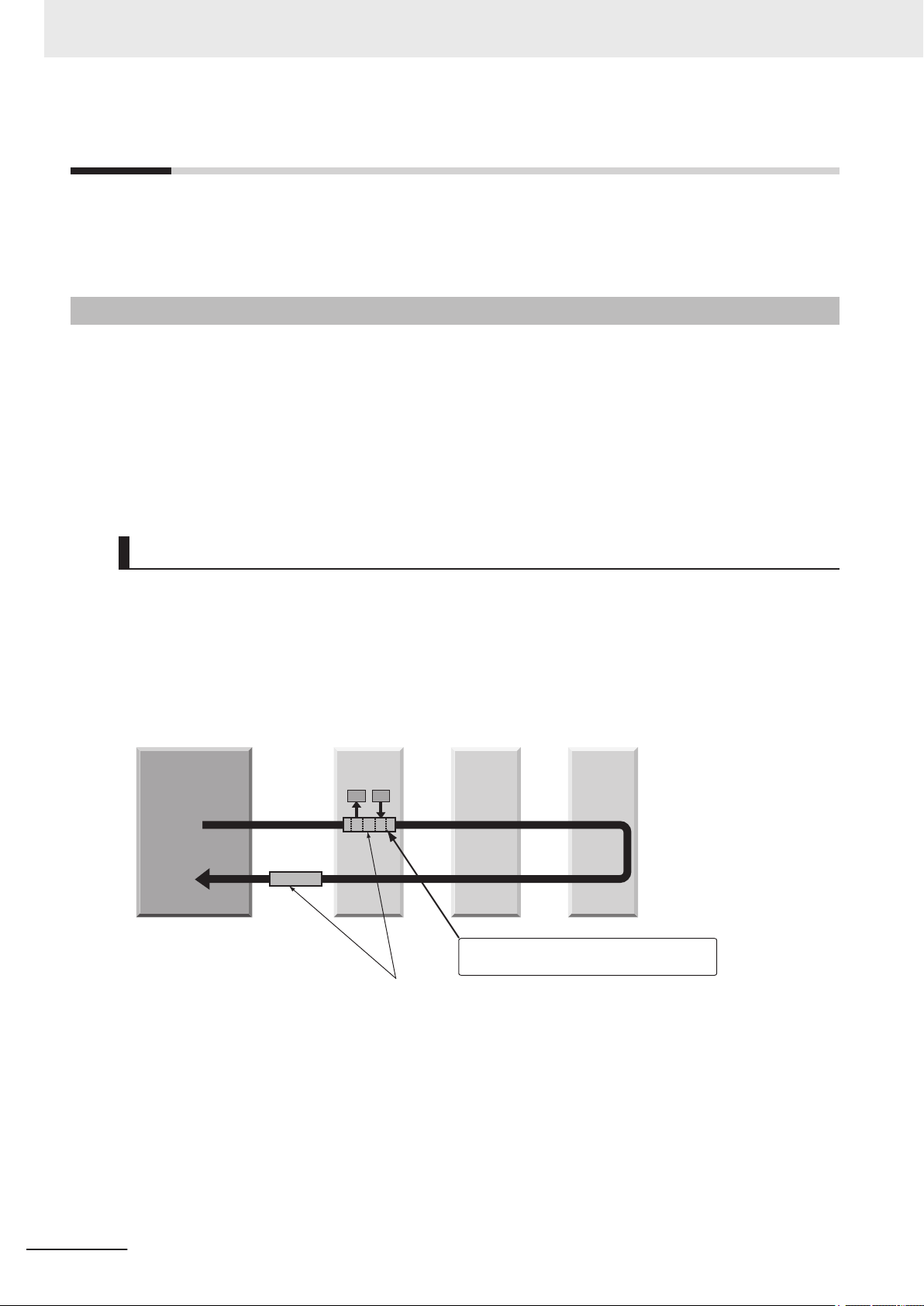
EtherCAT master
Slave
Data
Slave
Slave
Ethernet frames
IN
OUT
• The slave reads output data addressed to it.
• The slave writes input data.
2 Methods for Connecting and Communicating with External Devices
2-1
2-1-1
EtherCAT Connections
This section describes the communication settings , communication specifications, input/output formats, and the communication timing chart required for communications by EtherCAT between the
Sensor Controller and an external device.
Introduction to EtherCAT
EtherCAT (Ethernet Control Automation Technology) is a high-performance industrial network system
that enables faster and more efficient communications based on Ethernet.
Each node achieves a short communication cycle time by transmitting Ethernet frames at high speed.
Although EtherCAT is a unique communication protocol, standard Ethernet technology is used for the
physical layer, which means you can use Ethernet cables for wider applications.
And the effectiveness of EtherCAT can be fully utilized not only in large control systems that require
high processing speeds and system integrity, but also in small and medium control systems
How EtherCAT Works
In EtherCAT communication, Ethernet frames pass through all of the slave nodes.
When a frame passes through a slave node, the slave node reads and writes the data in the area that
is allocated to it in the frame in a few nanoseconds.
The Ethernet frames that are transmitted by the EtherCAT master pass through all EtherCAT slaves
without stopping. The last slave returns all of the frames, which again pass through all of the slaves
before returning to the EtherCAT master.
This mechanism ensures high speed and real-time data transmission.
2-4
The data exchanges that are cyclically performed between the EtherCAT master and EtherCAT slaves
use EtherCA
Each EtherCAT telegram consists of a telegram header (including the data length and one or more
slave addresses), data, and a working counter (i.e., check bits).
T telegrams
that are stored directly in the Ethernet frames.
FH/FHV Series Vision System User's manual for Communication Settings (Z342-E1)
Page 65

Ethernet
header
CRC
Ethernet data (1,498 bytes max.)
Data
Telegram
header
WKC
1st to nth EtherCAT telegrams
EtherCAT
header
1st EtherCAT
telegram
2nd EtherCAT
telegram
nth EtherCAT
telegram
EtherCAT frame
Ethernet frame
WKC: Working counter
2 Methods for Connecting and Communicating with External Devices
2-1 EtherCAT Connections
2
2-1-1 Introduction to EtherCAT
FH/FHV Series Vision System User's manual for Communication Settings (Z342-E1)
2-5
Page 66

EtherCAT master
Slave
Ethernet frame
Slave Slave
Slave
Ethernet
header
Ether
CAT
header
1st EtherCAT
telegram
2nd EtherCAT
telegram
3rd EtherCAT
telegram
CRC
Logical process data
Data a
Data b
Data c
2 Methods for Connecting and Communicating with External Devices
Types of EtherCAT Communications
The following 2 types of communications are available with EtherCAT.
PDO communications are processed in each EtherCAT communication cycle to refresh data continuously
. SDO communications are processed between PDO communications.
Process Data Communications (PDO Communications)
l
The process data communication function (PDO communications) cyclically transfers process data
in real-time.
The EtherCAT master maps the logical process data space to the nodes to achieve cyclic communications between the EtherCAT master and slaves.
l
Mailbox Communications (SDO Communications)
The mailbox communication function (SDO communications) is used to perform message communication.
Whenever necessary, the EtherCA
T master sends a command to a slave, and then the slave returns a response to the EtherCAT master.
The mailbox communication function (SDO communication) has the following functions.
• Reading and writing process data
• Setting slaves
• Monitoring slave status
2-6
FH/FHV Series Vision System User's manual for Communication Settings (Z342-E1)
Page 67

FH Sensor Controller
EtherCAT physical layer
Transitions of
communications
states
SDO (mailbox)
FH Unit application
Object dictionary
PDO mappings
PDO communications (cyclic)
EtherCAT data link layer
Registers Mailbox
Process data
FMMU SyncManager
Application layer
2 Methods for Connecting and Communicating with External Devices
2-1-2
Structure of CAN Application Protocol over EtherCAT (CoE)
EtherCAT allows the use of multiple protocols for communication. EtherCAT slave terminal adopts
CAN application protocol over EtherCA
T (CoE) as a device profile for CAN application protocol
is one of the open network standards, which provides the communication interface to apply to EtherCAT devices.
The following figure indicates the CoE structure in the EtherCAT coupler unit.
which
2-1 EtherCAT Connections
2
2-1-2 Structure of CAN Application Protocol over EtherCAT (CoE)
The object dictionary for the CAN application protocol is roughly classified into PDOs (process data
objects) and SDOs (service data objects).
PDOs consist of the mappable object dictionaries, and the contents in process data are defined by the
PDO mappings. PDOs are used for PDO communications to exchange process data periodically.
Moreover
, SDOs can read and write all object dictionaries and are used for non-periodic SDO (event-
driven message) communications.
In EtherCAT, by setting the object dictionaries for PDOs and SDOs using the CoE interface, EtherCAT
devices that have the same device profiles as the CAN application protocol can be provided.
FH/FHV Series Vision System User's manual for Communication Settings (Z342-E1)
2-7
Page 68

ESI files
Network
configuration
information
EtherCAT master
Configuration Tool
EtherCAT Slave
Terminal
EtherCAT
slave
Communications are started according to the
communications settings and the network
configuration based on the ESI files that are installed.
2 Methods for Connecting and Communicating with External Devices
2-1-3
EtherCAT Slave Information Files (ESI Files)
The setting information for an EtherCAT slave is provided as ESI file (EtherCAT Slave Information).
T
In EtherCA
and the network connection information for the connected slaves.
Installing ESI files into the network setup software (configuration tool) can generate the network con-
figuration information.
Downloading the generated network configuration information to the EtherCAT master enables you to
setup the EtherCAT network.
, its various communication settings are defined based on the ESI definition information
(*1)
ESI files for the FH/FHV can be downloaded from the OMRON website.
*1: If you are using Sysmac Studio, it is not necessary to install the ESI files in the network setup software (configuration tool). The ESI files for OMRON EtherCAT slaves have already installed in the Sysmac Studio. Auto-update function in the Sysmac Studio enables you to get the ESI files for the latest
models.
2-8
FH/FHV Series Vision System User's manual for Communication Settings (Z342-E1)
Page 69

Init
Pre-Operational
Safe-Operational
Operational
Power supply ON
2 Methods for Connecting and Communicating with External Devices
2-1-4
Transitions of Communications States
2-1 EtherCAT Connections
The EtherCAT master controls the state transition model for communication control of its slave terminals.
The following figure indicates the transition for the communication state since the power has been
turned ON.
2
2-1-4 Transitions of Communications States
The following table indicates whether or not data objects can be sent or received in each communication state.
SDO
Status
Init.
Pre-Operational (PreOp)
Safe-Operational
(Safe-Op)
Operational (Op) Possible Possible Possible
commu-
nications
Not possible
Possible
Possible Possible
Sending
PDOs
Not possible
Not possible
Receiv-
ing PDOs
Not possible
Not possible
Not possible
Description
Communications is in initialization. Communications are not possible.
Only SDO (message) communications are possible.
After the initialization, the network settings is initialized in this state.
Sending PDOs in addition to SDO (message)
communications are possible in this state.
The slave terminals can send Information such
as status with sending PDOs.
Normal state in communications.
The I/O data can be controlled with PDO communications.
FH/FHV Series Vision System User's manual for Communication Settings (Z342-E1)
2-9
Page 70

TxPDO
EtherCAT master
EtherCAT
Slave
Terminal
RxPDO
Status of EtherCAT Slave
Terminals and input data
from NX Units (Input Units)
Example: Built-in
EtherCAT port
on NJ-series
CPU Unit
Output data and motion
commands to NX Units
(Output Units)
2 Methods for Connecting and Communicating with External Devices
2-1-5
Process Data Objects (PDOs)
This section describes the process data objects (PDO) used in EtherCAT communications.
Introduction
Real-time data transfer in cyclic communication uses Process Data Objects (PDOs).
There are two types of Process Data Objects (PDOs): RxPDOs, which are used by the EtherCAT
slave terminal to receive data from the EtherCA
CAT slave terminal to send data to the EtherCAT master.
T master; and TxPDOs, which are used by the Ether-
2-10
The EtherCAT application layer can hold more than one object to enable the transfer of various process data of the EtherCA
T slave terminal.
The contents of the process data is defined in the PDO mapping objects.
EtherCA
T slave terminals support PDO mapping for I/O control.
FH/FHV Series Vision System User's manual for Communication Settings (Z342-E1)
Page 71

8
16
8
Object B
Object C
Object A
PDO_1
Object E
Object D
Object A
Object B
Object D
Index
02 hex
03 hex
01 hex
Sub
Index
UU hex
VV hex
TT hex
ZZ hex
YY hex
Object Contents
Mapping object
Object Dictionary
Application object
1ZZZ hex
6TTT hex
6UUU hex
6VVVHex
6YYY hex
6ZZZHex
6UUU
hex
UU
hex
6TTT
hex
TT
hex
6YYY
hex
YY
hex
PDO-Length : 32 Bit
2001 hex
01 hex
01 hex
2001 hex 01 hex *
1
Index
Sub
Index
Object Contents
8
Sysmac error status
Object Dictionary
1BFF hex
*1. This is expressed as 0x2001:01 on the Sysmac Studio.
Sysmac error status
512th transmit PDO mapping
PDO-Length : 8 Bit
Mapping
object
Application
object
2 Methods for Connecting and Communicating with External Devices
PDO Mappings
PDO mapping objects contain the I/O data for EtherCAT slave terminals. PDO mapping objects are
managed with indexes in the object dictionary: from 1600 to 17FF Hex for the RxPDO, and from 1A00
to 1BFF Hex for TxPDO.
PDO Mapping Scheme in EtherCAT
l
The following describes the PDO mapping scheme in EtherCAT.
Three application objects (Object A, B, and D) are allocated to the PDO (name: PDO_1) at index
1ZZZ Hex.
Like mentioned above, PDO mappings indicates how application objects are allocated to PDOs.
Indexes and sub-indexes are also allocated to application objects.
2-1 EtherCAT Connections
2
2-1-5 Process Data Objects (PDOs)
PDO Mapping for EtherCAT Slave Terminals
l
EtherCAT slave terminals have PDOs for each EtherCAT coupler unit and the Sensor Controller for
FH/FHV series.
Application objects are allocated by default (factory settigs) to PDOs for each unit.
The following figure describes a specific example for one of PDOs in a Sensor Controller for the
FH/FHV series.
FH/FHV Series Vision System User's manual for Communication Settings (Z342-E1)
2-11
Page 72

2
3
1
PDO B
PDO C
PDO A
PDO E
PDO D
PDO A
PDO B
PDO D
Index
Sub
Index
Object Contents
Sync Manager PDO
assignment objects
Mapping objects
PDO G
PDO F
Sync Manager entity Z
1C13 hex
1A00 hex
1A01 hex
1A02 hex
1A03 hex
1A04 hex
1A05 hex
1A06 hex
1A00 hex
1A01 hex
1A03 hex
2 Methods for Connecting and Communicating with External Devices
In the above example, a single application object is allocated to the PDO at index 1BFF Hex
(name: 512th transmission PDO mapping). This PDO is for TxPDO. The application object contains
the Sysmac error status at index 2001 Hex and sub-index 01 Hex.
Allocating PDOs
Scheme for Allocating PDOs to EtherCAT Slaves
l
Multiple PDOs can be allocated to an EtherCAT slave.
The following example indicates the PDO allocation.
Here, PDOs are allocated to index 1C12 Hex for the RxPDO, and 1C13 Hex for the TxPDO.
2-12
In the example, three PDOs (PDO A, PDO B, PDO D) are allocated to index 1C13 Hex for the
TxPDO.
Likewise, a PDO for the RxPDO is also allocated to index 1C12 Hex.
The above allocation defines the PDO types for communications between the EtherCAT master
and slave.
FH/FHV Series Vision System User's manual for Communication Settings (Z342-E1)
Page 73

2 Methods for Connecting and Communicating with External Devices
2-1-6
Service Data Objects (SDOs)
This section describes the service data objects (SDO) used in EtherCAT communications.
Introduction
EtherCAT slave terminals support SDO communications.
The EtherCAT master can set parameters and monitor status by reading and writing data from and to
entries in the object dictionary using SDO communications.
For the objects that SDO communications are available, refer to 2-1-27 Object Dictionary on page
2-87.
Abort Codes
The following table lists the abort codes for SDO communication errors.
Abort code value Meaning
05030000 Hex Toggle bit not changed
05040000 Hex SDO protocol timeout
05040001 Hex Client and server command specifiers not valid or unknown
05040005 Hex Out of memory area
06010000 Hex Unsupported access to an object
06010001 Hex Attempt to read a write-only object
06010002 Hex Attempt to write to a read-only object
06020000 Hex Non-exist object in the object dictionary
06040041 Hex Unable to map the object to the PDO
06040042 Hex Number and length for the mapped object exceed the PDO length.
06040043 Hex General parameter incompatibility
06040047 Hex General internal incompatibility in the device.
06060000 Hex Access failure due to a hardware error.
06070010 Hex Mismatch of data type and service parameter length
06070012 Hex Data type mismatch and service parameter length is too long.
06070013 Hex Data type mismatch and service parameter length is too short.
06090011 Hex Missing sub-index.
06090030 Hex Parameter value is out of range. (Only for write-access)
06090031 Hex Written parameter value is too high.
06090032 Hex Written parameter value is too low.
06090036 Hex Maximum value is smaller than minimum value.
08000000 Hex General error
08000020 Hex Data cannot be transferred or stored to the application.
08000021 Hex Data cannot be transferred or stored to the application because of local control.
08000022 Hex Data cannot be transferred or stored to the application because of the present device
state.
08000023 Hex Failed to dynamically create the object dictionary, or no object dictionary exists.
2-1 EtherCAT Connections
2
2-1-6 Service Data Objects (SDOs)
FH/FHV Series Vision System User's manual for Communication Settings (Z342-E1)
2-13
Page 74

2 Methods for Connecting and Communicating with External Devices
2-1-7
Communications between Master and Slaves for EtherCAT
This section describes the communication modes between the master and slaves for EtherCAT and
the communication modes for EtherCA
T slave terminals.
Communication Modes for Communications between Master and
Slaves for EtherCA
Free-run Mode (FH/FHV series not supported)
l
In the free-run mode, a slave performs the I/O processing (updating the I/O data) asynchronously
to the communication cycle of the master.
DC Mode
l
In the DC mode, a slave performs the I/O processing (updating the I/O data) synchronously with
the communication cycle of the master. The synchronization in EtherCA
distributed clock (DC) to share the same clock in the master and slaves. Interruptions (Sync0) are
generated in the slaves at precise intervals based on the clock. Each slave performs the I/O processing at the precise timing.
T
T communications uses a
Communication Modes for EtherCAT Slave Terminals
The FH/FHV series support DC mode. They do not support the free-run mode.
Communication Cycle
The communication cycle is determined by the settings for it in the EtherCAT master.
For details of communication cycle supported by the built-in EtherCAT port in the NJ series CPU units,
refer to
NJ-series CPU Unit Built-in EtherCAT Port User’s Manual (Cat. No. W505).
2-14
FH/FHV Series Vision System User's manual for Communication Settings (Z342-E1)
Page 75

2 Methods for Connecting and Communicating with External Devices
2-1-8
Communication Method of FH Sensor Controller Connected by
EtherCA
With commands and responses via communications between an EtherCAT master and a Sensor Controller, the master can control the Sensor Controller and make it output data after measurement.
T
o connect a Sensor Controller of the FH series to an NJ series CPU unit by EtherCAT, use Sysmac
Studio (standard edition) version 1.09 or later.
Using the Sysmac Studio, the Sensor Controller of the FH series is registered to the EtherCAT slave
configuration on the Edit Network Configuration tab page.
For details of the registration procedures, refer to Controller Configurations and Setup in the Sysmac
Studio Version 1 Operation Manual (Cat. No. W504).
Precautions for Correct Use
When Sysmac Studio is used in a high load environment, such as input of measurement triggers at short intervals while connected online to an FH, there may be deviations in the measurement processing time.
Additional Information
Up to eight Sensor Controllers of the FH series can be connected to an NJ-series Controller by
EtherCAT
T
.
2-1 EtherCAT Connections
2
2-1-8 Communication Method of FH Sensor Controller Connected by EtherCAT
In EtherCAT communications, communications are performed via I/O ports in the following six areas in
the Controller. The I/O ports in the Sysmac Error Status Area are used only when a CPU Unit of the
NJ series is connected as a EtherCA
(1) I/O ports in the
Command/response
method
Data output after
measurements
Error status
User area
Command Area
(2) I/O ports in the
Response Area
(3) I/O ports in the Data
Output Area
(4) I/O ports for Sysmac
Error Status Area
(5) I/O ports in the user
input area
(6) I/O ports in the user
output area
T master.
These I/O ports are used that you write control commands to perform for the Sensor Controller.
These I/O ports are used that the Sensor Controller
writes the results which the control commands written
in the Command Area were performed.
These I/O ports are used that the Sensor Controller
writes the measurement parameters, judgment results,
and other results after measurements are performed.
These I/O ports are used that the Sensor Controller
writes the error status. V
and V
ision Tool used together.
These I/O ports are used that you write the data that
you defined for the Sensor Controller.
These I/O ports are used that the Sensor Controller
write the data that you defined for the Sensor Controller.
alid only for Sysmac Studio
FH/FHV Series Vision System User's manual for Communication Settings (Z342-E1)
2-15
Page 76

I/O ports in the Command Area
You write the following control
commands for the Vision Sensor.
• Control signals
• Command codes
• Command parameters
I/O ports in the Response Area
The Vision Sensor writes the
execution results.
Controller (master)
I/O ports in the Data Output Area
The Vision Sensor writes the
output data.
I/O ports for Sysmac Error Status Area
The Vision Sensor writes the
error status.
Command/
response
method
Data
output
after
measurements
Error status
The Vision Sensor executes the
control commands written to the
I/O ports in the Command Area.
28 bytes
Vision Sensor (slave)
Commands
Responses
External
outputs
*1
The Vision
Sensor writes
the values
measured by
processing
item A.
The Vision Sensor writes the execution
results to the I/O ports in the Response
Area in the Controller.
• Status signals
• Command codes
• Response codes
• Response data
Execution
The Vision Sensor writes the
error status to the I/O ports in the
Sysmac Error Status Area.
• Sysmac error status
1 byte
24 bytes
Operation is
performed by
executing the
measurement
flow (32 to
256 bytes).
Communications
Module
Data is written to the Communications Module.
• Measurement Flow
Execution of processing
item for the Output Unit.
*2
Execution of processing item A
You write data that you defined
for the FH Sensor Controller to
these I/O ports.
Data that you defined for the
FH Sensor Controller is written
to these I/O ports from the
FH Sensor Controller.
User area
The FH Sensor Controller proceed
with processing using the written
data.
*3
32 byte
32 byte
Input
Output
The FH Sensor Controller writes
data that you defined for the
FH Sensor Controller to these I/O
ports.
*3
I/O ports in the user input area
I/O ports in the user output area
2 Methods for Connecting and Communicating with External Devices
*1: You can use output controls (handshaking) to prevent output data from being externally output from
the communications buffer until the Controller (master) turns ON the Result Set Request signal to request the output data.
*2: For details of the Output Units outputting measurement data, refer toSettings Required for Data
Output
on page 1-21.
*3: Use the Macro Customization Function to input and output to the User Area. For details of the
Macro Customization Function, refer to EtherCAT communication of the IO Module List in the Vision
System FH Macro Customize Functions Programming Manual (Cat. No. Z367).
2-16
FH/FHV Series Vision System User's manual for Communication Settings (Z342-E1)
Page 77

Line 0
Line 1
Line 6
Line 7
NJ-series Controlle
r
You can specify
the output data
size for each line.
FH
Line 0
PDO
communications
Line 1
PDO
communications
Line 6
PDO
communications
Line 7
PDO
communications
2 Methods for Connecting and Communicating with External Devices
Communications in Multi-line Random-trigger Mode
In Multi-line Random-trigger mode, a Sensor Controller for the FH series can control up to eight lines.
In Multi-line Random-trigger mode, the I/O ports (areas) for communications between the Sensor Controller and the master are allocated as shown below.
Command/response method
Data output after measurements I/O ports in the Data Output Area
User area
Error status
Independent areas for PDO communications are allocated for each line by allocating a Module (line) to
each EtherCAT communication slot using Sysmac Studio (standard edition).
I/O ports in the Command Area
I/O ports in the Response Area
I/O ports in the User Input Area
I/O ports in the User Output Area
I/O ports for Sysmac Error Status
Area
Allocated for each line.
The same for all lines.
2-1 EtherCAT Connections
2
2-1-8 Communication Method of FH Sensor Controller Connected by EtherCAT
Available Size for Output Data
l
FH/FHV Series Vision System User's manual for Communication Settings (Z342-E1)
The upper limits for the output data size depend on the number of lines and User Area to be used
as shown below
Number of lines Not Using User area Using User area
1 line Max. 256 bytes Max. 256 bytes
2 lines
3 lines
4 lines
5 lines Max. 128 bytes
6 lines Max. 128 bytes
7 lines
8 lines
.
2-17
Page 78

2 Methods for Connecting and Communicating with External Devices
Minimum PDO Communication Cycle Time
l
Do not set the communication cycle (PDO communication cycle time) for EtherCAT communications to a value lower than the minimum time in the following table.
The minimum communication cycle time (PDO communication cycle time) depends on the number
of lines to control, the number of bytes for output data, and the User Area to use as shown below.
In Multi-line Random-trigger mode, the minimum value for the communication cycle is the minimum
value for the maximum byte size for each line.
If the communication cycle (PDO communication cycle time) were set lower than the minimum value below
tion will become unavailable.
Not Using User area
, a slave application error (AL status code: 0x0035) will occur and EtherCAT communica-
Number of lines to
be controlled
1 line 125 μs 250 μs
2 lines 250 μs
3 lines 250 μs 500 μs
4 lines 500 μs
5 lines 500 μs 1000 μs
6 lines 500 μs 1000 μs Unavailable
7 lines 500 μs 1000 μs Unavailable
8 lines 1000 μs Unavailable
Using User area
Number of lines to
be controlled
1 line 125 μs 250 μs
2 lines 250 μs 500 μs
3 lines 500 μs
4 lines 500 μs 1,000 μs
5 lines 500 μs 1,000 μs Unavailable
6 lines 1,000 μs Unavailable
7 lines 1,000 μs Unavailable
8 lines 1,000 μs Unavailable
32 bytes 64 bytes 128 bytes 256 bytes
32 bytes 64 bytes 128 bytes 256 bytes
Byte size of output data
Byte size of output data
2-18
FH/FHV Series Vision System User's manual for Communication Settings (Z342-E1)
Page 79

2 Methods for Connecting and Communicating with External Devices
Applicable Models
• OMRON
OK: Can connect, Cond.: Only some models can connect, NG: Cannot connect
Interface
Series CPU unit
SYSMAC NJ/NX NJ501, NJ301, NJ101,
NX701
• Beckhoff
TwinCA
T PC edition, Industrial PCs, Embedded PCs
(When you use a Beckhoff’s master, contact us to get an ESI file for Sensor Controllers of the FH
series.)
Direct connection with
CPU unit (Built-in port)
OK -
Connection via master
unit
2-1 EtherCAT Connections
2
2-1-8 Communication Method of FH Sensor Controller Connected by EtherCAT
FH/FHV Series Vision System User's manual for Communication Settings (Z342-E1)
2-19
Page 80

2 Methods for Connecting and Communicating with External Devices
2-1-9
Communications Settings
The following settings are required to use EtherCAT communications.
1. Communication Module settings
(Startup settings)
↓
2. Communications
specifications settings
↓
3.Output data settings
(processing item registration)
↓
4. EtherCA
configuration settings
5. Communications test
T network
↓
··· The communication method to be used is determined by selecting a communication module.
For details, refer to 2-1-10 Communications Module Settings
(Startup Settings) on page 2-22.
···
··· The data output to the Data Output Area is registered in the Out-
··· Using Sysmac Studio, register Sensor Controllers of the FH/FHV
··· In normal communication state, ECAT RUN-LED on the Sensor
The communications specifications are set for the communications method of the Communication Module selected in step 1.
Moreover, The data size settings output to the Data Output Area
and whether or not to use the User Area are also set.
For details, refer to
tings on page 2-23.
put Unit.
The Output Unit is placed in the processing flow in the same way
as for other processing items.
For details, refer to 2-1-12 Output Data Settings (Processing
Item Registration) on page 2-28.
series in the EtherCA
Moreover, When multiple lines are used in Multi-line Randomtrigger Mode, set the Communication Module for each line.
For details, refer to 2-1-14 EtherCAT Network Configuration Set-
tings on page 2-37.
Controller lights green.
If communications were not working properly, check the communications setup from step 2.
If communications were not performed properly
registered in the troubleshooting of the Sysmac Studio. Check
them to solve the problem.
For details, refer to 2-1-15 Communication Test on page 2-38.
2-1-11 Communication Specifications Set-
T slave configuration.
, error events are
2-20
FH/FHV Series Vision System User's manual for Communication Settings (Z342-E1)
Page 81

Communications
Module setting
Communications
specifications settings
Output data
designation
Output data
designation
Communications
Module setting
Output data
designation
Communications
Module setting
....
....
Settings on
the window
for line 0
Settings on
the window
for line 1
Settings on
the window
for line 7
The output data is designated
according to the output data
size that was set on the
window for line 0.
The output data is designated
according to the output data
size that was set on the
window for line 0.
Set [Fieldbus] to [EtherCAT].
Set [Fieldbus] to [EtherCAT].
Set [Fieldbus] to [EtherCAT].
• The communications settings
(e.g., communications cycle):
Are the same for all lines.
• Number of output data bytes
(output size):
Set for each line.
2 Methods for Connecting and Communicating with External Devices
Additional Information
Communications are set up as shown below when you use the Multi-line Random-trigger mode.
2-1 EtherCAT Connections
2
2-1-9 Communications Settings
FH/FHV Series Vision System User's manual for Communication Settings (Z342-E1)
2-21
Page 82

2 Methods for Connecting and Communicating with External Devices
2-1-10
Communications Module Settings (Startup Settings)
1 On the Main window, click Tool -
System Settings to open the system settings.
2 On the Multiview Explorer on the left, select System settings - Startup - Startup setting and
then click the Communication tab.
3 In the Communication Module Selection Area, select EtherCA
Apply.
in the Fieldbus, and then click
T
4 Click Data save in the Toolbar
.
5 On the Main window, click Function - System restart.
6 Click OK in the System restart dialog box to restart the Sensor Controller.
When the Sensor Controller was restarted, the set Communication Module will operate with the
default settings.
7 Set the IP address and other parameters for external devices such as a PLC.
Precautions for Correct Use
If you will use the Multi-line Random-trigger mode for EtherCAT communications for multiple
lines, use the following procedure to set the Communications Module.
T
(1) In the Communications Module settings for line 0, set the Fieldbus Box to EtherCA
ting to the Vision Sensor, and then restart the system.
(2) After the system has been restarted, set the Fieldbus Box to
Module settings for line 1, save the setting to the Vision Sensor, and then restart the system. Repeat this step for the rest of the lines.
EtherCAT in the Communications
, save the set-
2-22
FH/FHV Series Vision System User's manual for Communication Settings (Z342-E1)
Page 83

2 Methods for Connecting and Communicating with External Devices
Additional Information
You can save the Communication Module settings to a file.
Use the System data or System + Scene group 0 data option for saving settings to a file.
For details, Refer to Saving Settings Data to the Controller RAM Disk or an External Storage
Device in the Vision System FH/FHV Series User
’s Manual (Cat. No. Z365).
2-1 EtherCAT Connections
2-1-11
Communication Specifications Settings
Here, set output data size, output handshaking, and output controls to perform EtherCAT communications.
Precautions for Correct Use
• Use the same communications specifications settings for the Sensor Controller and the external device.
• Do not input signals to EtherCA
tem settings.
• Before you set the communications specifications, set the Communications Module to
EtherCAT.
Restart the system after you save the data to the Vision Sensor.
For details, Refer to 2-1-10 Communications Module Settings (Startup Settings) on page
2-22.
1 On the Main window, click Tool
T from an external device while performing the EtherCAT sys-
- System Settings to open the system settings.
2 Select System Settings and then select Communications - EtherCAT.
Communication settings window appears.
2
2-1-11 Communication Specifications Settings
3 Set each item.
FH/FHV Series Vision System User's manual for Communication Settings (Z342-E1)
2-23
Page 84

2 Methods for Connecting and Communicating with External Devices
Setting item
Judge output polarity
Error output polarity
Output control
Output period
[cycle]
Output time
[cycle]
Timeout [s]
Setting value
[Factory default]
• ON at OK
• [ON at NG]
• [ON at error]
• OFF at error
• [None]
• Handshaking
2 to 5,000
[2]
1 to 1,000
[1]
0.5 to 120.0
[10.0]
Description
ON at OK:
ON when the judgment result is OK.
For the overall judgment, ON when all judgment
results are OK.
ON at NG:
ON when the judgment result is NG.
For the overall judgment, ON when one of the
judgment results is NG.
ON at error:
ON when an error occurs.
OFF at error:
OFF when an error occurs.
None:
The Sensor Controller outputs measurement results without synchronizing with external devices.
Handshaking:
The Sensor Controller outputs measurement results with synchronizing with external devices.
Set the cycle by which measurement results are
output.
Set the number of cyclic communications of the
EtherCA
to output the measurement results from the Sensor Controller.
Set the cycle by which the output of measurement
results are held.
Set the number of EtherCAT PDO communication
cycles to hold the output from the Sensor Controller
Valid only when Handshaking is set to Output
Control.
Set the timeout time.
A timeout error will occur if external devices could
not perform handshaking within the time set here.
T PDO communication cycle after which
.
2-24
FH/FHV Series Vision System User's manual for Communication Settings (Z342-E1)
Page 85

2 Methods for Connecting and Communicating with External Devices
Setting item
Line n Data Output
number
Setting value
[Factory default]
• Result Data Format 0
(DINT 8)
• Result Data Format 1
(DINT 16)
• Result Data Format 2
(DINT 32)
• Result Data Format 3
(DINT 64)
• Result Data Format 4
(LREAL 4)
• Result Data Format 5
(LREAL 8)
• Result Data Format 6
(LREAL 16)
• Result Data Format 7
(LREAL 32)
• Result Data Format 8
(DINT 2 + LREAL 3)
• Result Data Format 9
(DINT 4 + LREAL 6)
• Result Data Format
10 (DINT 8 + LREAL
12)
• Result Data Format
11 (DINT 16 +
LREAL 24)
Description
Set the number of data items to output for each
line.
There are two types in the output data size: 4
bytes (DINT) and 8 bytes (LREAL).
Select the output data size and the number of outputs from the types below
Result Data Format 0
(DINT 8)
Result Data Format 1
(DINT 16)
Result Data Format 2
(DINT 32)
Result Data Format 3
(DINT 64)
Result Data Format 4
(LREAL 4)
Result Data Format 5
(LREAL 8)
Result Data Format 6
(LREAL 16)
Result Data Format 7
(LREAL 32)
Result Data Format 8
(DINT 2 + LREAL 3)
Result Data Format 9
(DINT 4 + LREAL 6)
Result Data Format 10
(DINT 8 + LREAL 12)
Result Data Format 1
(DINT 16 + LREAL 24)
.
Eight 4-byte data items
are output. (Total: 32
bytes)
Sixteen 4-byte data
items are output. (Total:
64 bytes)
Thirty-two 4-byte data
items are output. (Total:
128 bytes)
Sixty-four 4-byte data
*1
items are output. (Total:
256 bytes)
Four 8-byte data items
are output. (Total: 32
bytes)
Eight 8-byte data items
are output. (Total: 64
bytes)
Sixteen 8-byte data
items are output. (Total:
128 bytes)
Thirty-two 8-byte data
*1
items are output. (Total:
256 bytes)
wo 4-byte data items
T
and three 8-byte data
items are output, for a
total of five data items.
(Total: 32 bytes)
Four 4-byte data items
and six 8-byte data
items are output, for a
total of 10 data items.
(Total: 64 bytes)
Eight 4-byte data items
and twelve 8-byte data
items are output, for a
total of 20 data items.
(Total: 128 bytes)
Sixteen 4-byte data
items and twenty-four 8-
*1
byte data items are out-
1
put, for a total of 40 data items. (Total: 256
bytes)
2-1 EtherCAT Connections
2
2-1-11 Communication Specifications Settings
FH/FHV Series Vision System User's manual for Communication Settings (Z342-E1)
2-25
Page 86

2 Methods for Connecting and Communicating with External Devices
Setting item
Setting value
[Factory default]
• Result Data Format
12 (ByteArray 32
byte)
• Result Data Format
13 (ByteArray 64
byte)
Description
Result Data Format 12
(ByteArray 32 byte)
Result Data Format 13
(ByteArray 64 byte)
Result Data Format 14
(ByteArray 128 byte)
A character string of 32
bytes is output.
A character string of 64
bytes is output.
A character string of
128 bytes is output.
• Result Data Format
14 (ByteArray 128
byte)
• Result Data Format
15 (ByteArray 256
byte)
User area
• [OFF]
• ON
*1. When you control six to eight lines in Multi-line Random trigger mode, you cannot use the output
data size of 256 bytes.
Result Data Format 15
(ByteArray 256 byte)
Set whether or not to use the user area (user input
area/user output area) for each line.
A character string of
256 bytes is output.
4 Click Apply.
Precautions for Correct Use
If you change any of the Line N Data Output Number and User area settings, restart the Con-
.
troller
Additional Information
If you use alignment, select the data type of the output data according to the application.
• DINT Data:
This data type holds a single-precision floating-point number
.
Coordinate values are multiplied by 1,000 and are output as integers.
Only 1/1,000 of the precision is output.
• LREAL Data:
This data type holds a double-precision floating-point number.
If you use alignment, coordinate values are output as double-precision floating-point numbers.
This allows you to output the actual values to an external device.
However, processing 64-bit calculations on the NJ-series Controller or other PLC will be slower than processing 32-bit calculations.
• ByteArray Data:
This is used to output a character string. (Other than characters cannot be output.)
1) Select Result Data Format on the EtherCAT setting screen in the Sensor Controller of the
FH/FHV series. (Data with Array of Byte format is output to the NJ series Controller.)
2) Use the AryToString command in the program on the NJ series Controller to convert the
received data with Array of Byte format to String format.
2-26
FH/FHV Series Vision System User's manual for Communication Settings (Z342-E1)
Page 87

2 Methods for Connecting and Communicating with External Devices
EtherCAT Communications Settings for Multi-line Random-trigger
Mode
When you use Multi-line Random-trigger mode to perform EtherCAT communications on multiple lines,
you can only configure EtherCAT communication settings on line 0 Setting tab page.
The EtherCA
Output control Common settings for all lines
Output period Common settings for all lines
Output setting Set for each line.
T communication settings on multiple-line are as follows.
Setting item Description
The settings of the Fieldbus data output for each line vary depending on
the settings of the number of Data Output.
For details, refer to 2-1-12 Output Data Settings (Processing Item Regis-
tration) on page
2-28.
2-1 EtherCAT Connections
2
2-1-11 Communication Specifications Settings
FH/FHV Series Vision System User's manual for Communication Settings (Z342-E1)
2-27
Page 88

2 Methods for Connecting and Communicating with External Devices
2-1-12
Output Data Settings (Processing Item Registration)
Here, set the output items and output format to be used with EtherCAT.
This processing item is not available in the FHV series. When you set output data in the FHV series,
refer to 2-1-13
Setting Output Data (Numerical V
alues/Character Strings) on page 2-31.
Registering Processing Items
Register the processing items for data output in the measurement flow.
1 Click Edit flow in the T
oolbar.
2 Select the Fieldbus Data Output processing item in the processing item tree.
3 Click Append.
The Fieldbus Data Output processing item is added at the bottom of the unit list (flow).
4 Click the Fieldbus Data Output icon and set the data output items and data format.
For details of the settings, refer to the following.
Setting the Output Data on page 2-29
Precautions for Correct Use
Fieldbus Data Output
Perform the communication settings before the settings of Fieldbus Data Output.
Note that if you changed the communication settings after the settings of Fieldbus Data Output,
the changed settings will not be displayed on the Fieldbus Data Output setting display.
2-28
FH/FHV Series Vision System User's manual for Communication Settings (Z342-E1)
Page 89

2 Methods for Connecting and Communicating with External Devices
Additional Information
• Depending on the Data Output Number setting for the line, you can set from 4 to 64 data
items for output with one data output processing item.
Examples:
DINT16: You can register up to 16 data items.
LREAL 24: Y
For the number of data items that you can output for each Data Output Number setting., refer
to 2-1-11 Communication Specifications Settings on page 2-23.
If you need to output more data items than given above, use more than one Output Unit.
However, the data is output to the same destination, so if you do not control the output, the
data that was output first will be overwritten by the subsequent data.
Use the following method to read each set of output data.
• Controlling Data Output with Handshaking
When handshaking is used to control data output, the timing of outputting the data is controlled by I/O signals.
Each time that data is output, read the output data and move it to a different part of I/O
memory in the PLC.
For more information on handshaking, refer to Data Output Control with Handshaking on
page 1-25.
• Data is output in the order of registration in the measurement flow, with each data output
processing item executed at a different timing. (Data output is executed in the order that it is
registered in the measurement flow.)
For details, refer to Outputting the Measurement Data on page 1-18.
ou can register up to 24 data items.
2-1 EtherCAT Connections
2
2-1-12 Output Data Settings (Processing Item Registration)
Setting the Output Data
Set the output data with expressions.
Set the expression for each four-byte data (DINT) and eight-byte data (LREAL).
Additional Information
The Fieldbus Data Output setting item changes according to the EtherCAT communications settings. Set the total output data size (256 bytes max.) and the number of data items to output (64
max.) in the EtherCAT
communications settings in advance.
1 Click the Fieldbus Data Output icon in the measurement unit list (flow).
2 The Fieldbus Data Output window is displayed.
The DINT Setting and LREAL Setting tabs and the number of the output data are displayed
according to the EtherCAT communication settings.
3 In the item tab area, click either tab,
The DINT Setting and LREAL Setting tabs are displayed according to the EtherCA
nication settings.
DINT Setting or LREAL Setting.
T commu-
4 In the list, click the output data number to set the expression.
FH/FHV Series Vision System User's manual for Communication Settings (Z342-E1)
2-29
Page 90

2 Methods for Connecting and Communicating with External Devices
The selected output data number is displayed under the list.
5 Click
Specify the processing items, measurement results, and measurement data in the expression.
Arithmetic or function calculations can be applied to the measurement data to output.
For details of the calculation settings, refer to Calculation in the Vision System FH/FHV Series
Processing Items Reference Manual (Cat. No. Z341).
6 Click
The entered comment will be displayed in the detailed results area on the Main window.
For example,
stead of Expression 0 in the detailed results areas on the Main window.
next to the expression text box and set the expression.
for the Comment text box and enter the description for the expression.
Test was entered as the comment for the expression 0, Test will be displayed in-
7 Repeat step 4 to 5 to set expressions for each output data number.
8 In the item tab area, click either tab, DINT Setting or LREAL Setting and set the expressions
in the same way as for step 3 to 5 above.
Additional Information
2-30
If you delete one of the expressions that is set for an output data number, 0 is output for the
output data for that number.
FH/FHV Series Vision System User's manual for Communication Settings (Z342-E1)
Page 91

2 Methods for Connecting and Communicating with External Devices
2-1-13
Setting Output Data (Numerical Values/Character Strings)
Registering Processing Items
Register the processing items for data output in the measurement flow.
1 In the Main window, click Edit flow in the Toolbar
.
2 Click Result output (I/O) in the processing item tree.
3 Click Append.
The Result output (I/O) processing item is added at the bottom of the unit list (flow).
2-1 EtherCAT Connections
2
2-1-13 Setting Output Data (Numerical Values/Character Strings)
4 Click Result output (I/O) icon in the unit list (flow) or Set to set the output device and the
output data.
FH/FHV Series Vision System User's manual for Communication Settings (Z342-E1)
2-31
Page 92

2 Methods for Connecting and Communicating with External Devices
Setting the Output Device
Here, set a communication method when data is output.
1 Click Result output (I/O) icon in the unit list (flow) or Set to set the output device and the
output data.
The Result output (I/O) setting window is displayed.
2 Click Output setting.
The Output setting window is displayed.
3 Click at the right side of the Output device text box to select the communication method to
use.
2-32
FH/FHV Series Vision System User's manual for Communication Settings (Z342-E1)
Page 93

(a)
(b)
(c)
(c)
2 Methods for Connecting and Communicating with External Devices
Precautions for Correct Use
• The displayed output device is determined based on the selection of Communication
module in the
System settings in the item tab.
• Executing measurements without an output device selected causes a failure (NG: No measurement) in the judgment of the processing unit.
Setting the Output Data
Here, set the data to output such as processing item data or fixed character strings.
1 In the item tab area, click Output data.
The Result output (I/O) setting window is displayed.
2-1 EtherCAT Connections
2
2-1-13 Setting Output Data (Numerical Values/Character Strings)
a) Setting data display area
The No. (output number), Offset (indicating the byte position from the beginning), Data type
(integer
, double, string), Data, Value, and Title (data description) are displayed in this area.
A value is displayed when a variable is assigned to data.
b) Output data display area
Contents in the output data display area in binary (Hex) are displayed in this area.
c) Button
Button Description
Moves the selected data up one position.
Moves the selected data down one position.
Adds new data to the selected data position.
Deletes the selected data. The following data moves up after the deletion.
Edits the selected data.
FH/FHV Series Vision System User's manual for Communication Settings (Z342-E1)
2-33
Page 94

2 Methods for Connecting and Communicating with External Devices
Button Description
Saves the current settings and returns to the previous view.
Discards the current settings and returns to the previous view.
2 In the list, select the output data number to set the output and then click Insert.
The following Output data editing dialog box is displayed.
Setting item
Setting value
[Factory default]
Description
• Integer
Data type
• Double
Sets the data type.
• String
*1
Data -
There are two input methods.
• Enter strings directly
• Assign variables
Title - Enters the description for data.
String settings Valid when String is selected in the Data type.
Size
Character
code
*1. Any arithmetic expression cannot be used. If it is used, it will be handled as character strings.
0 to 4,095
[10]
[0] Sets the code page according to the language to be used.
Sets the number of characters.
• Character code: Specify the following code page for each language.
Language Code page Language Code page Language Code page
Japanese 932 English 1252
German 1252 French 1252
Italian 1252 Spanish 1252 Korean 949
Vietnamese 1258 Polish 1250
Chinese
(simplified)
Chinese
(traditional)
936
950
2-34
• The default 0 is no language-dependent letters in ANSI code page.
• If non-existing code page is selected, corresponding data is handled as invalid data (NULL).
3 Click at the right side of the Data type text box to select the data to output.
Integer, Double, or String are selectable.
FH/FHV Series Vision System User's manual for Communication Settings (Z342-E1)
Page 95

2 Methods for Connecting and Communicating with External Devices
Data type Description
• Entered data is handled as four-byte data.
• Allowable entering range is a range of signed INT.
Integer
Double
String
• When string variables are specified for data, character strings like digits which
can be converted into numerical values will be converted and output.When decimal digits are included, they are truncated.Moreover
they are not convertible.
• Entered data is handled as eight-byte data.
• The allowable entering range is a range of eight-byte floating decimal value.
• When string variables are specified for data, character strings like digits which
can be converted into numerical values will be converted and output. Moreover,
they are handled as “0” if they are not convertible.
• Entered data is set based on specified Size.
Example: Size is four and the entered data is ABCD.
ABCD → ABC+NULL
• The number of allowable entering characters is up to 4,095.
If this limit is exceeded, nothing is displayed and output.
• When NULL is included in the entered character string, the character string fol-
lowing NULL is not output.
• The following escape sequence codes can be entered. The entered escape se-
quence codes are handled as fixed character strings.
\N: Carriage return, \r: Line feed, \t: Tab, \xXX: ASCII code specified by “XX”
(numerical value), \”: Double quotation mark, \\: Backslash
2-1 EtherCAT Connections
, they are handled as “0” if
2
2-1-13 Setting Output Data (Numerical Values/Character Strings)
4 Enter data into Data text box.
Data that can be output with one data No. is a range only to be handled as one string.
1) When directly entering an output content into the Data text box.
A string enclosed with ” “ (double quotation marks) handled as one string and the rest following it is not output.
Example: “AA”TEST → only “AA” is output.
2) In the case where assignment variable is assigned o data:
Directly enter a variable name (Scene variable: SC.~) or specify a variable in Variable
assignment window displayed by clicking
• Only one variable is valid for one data No.
Example: SC.A$+SC.B$ → Only SC.A$ is output.
When a fixed string, e.g. AA, is entered before a variable, the subsequent variable is also
•
handled as a fixed string.
Example: AA+SC.AA& → “AA+SC.AA&”
• When “String” is selected in the “Data type” but “Integer” or “Double” is set to the varia-
ble, then the variable is converted to a string and then output.
.
FH/FHV Series Vision System User's manual for Communication Settings (Z342-E1)
2-35
Page 96

2 Methods for Connecting and Communicating with External Devices
5 Enter Title that indicates the content of output data.
6 When
set.
Example:
String is selected in Data type, the following items in String setting area also needs to be
2-36
7 Click OK in the end of entering data to close the settings.
FH/FHV Series Vision System User's manual for Communication Settings (Z342-E1)
Page 97

2 Methods for Connecting and Communicating with External Devices
2-1-14
EtherCAT Network Configuration Settings
To communicate with an NJ series Controller using EtherCAT, use the Sysmac Studio to register the
Sensor Controller of the FH/FHV series to the network configuration.
Precautions for Correct Use
To connect the Sensor Controller of the FH/FHV series to an NJ/NX series Controller by EtherCAT
, first connect Sysmac Studio to with the Sensor Controller online and then perform the
EtherCAT network configuration.
Registering the Sensor Controller in the EtherCAT Slave Configuration
Using the Sysmac Studio, the Sensor Controller of the FH/FHV series is registered to the EtherCAT
slave configuration on the Edit Network Configuration tab page.
For details of the registration procedures, refer to Controller Configurations and Setup in the
Studio Version 1 Operation Manual (Cat. No. W504).
Precautions for Correct Use
Sysmac
2-1 EtherCAT Connections
2
2-1-14 EtherCAT Network Configuration Settings
Use Sysmac Studio Standard Edition version 1.09 or later to perform the settings for the EtherCAT connections between the Sensor Controller of the FH series and an NJ-series Controller.
Setting the Data Output Size
Use the Sysmac Studio to assign individual PDO communication area for each line in the master according to the Data Output Number settings in the EtherCAT communication specifications settings in
the Sensor Controller of the FH/FHV series.
There are two setting methods.
Online Settings
l
When the data output size has already set in the Sensor Controller of the FH/FHV series, follow the
procedures below to perform the settings for the Sysmac Studio.
1 Connect the Sysmac Studio to the Sensor Controller of the FH/FHV series on-line.
2 Make the Sensor Controller of
the Sysmac Studio.
f-line after on-line connection, the setting data will be loaded to
3 PDO communication areas will be assigned in the master according to the setting conditions of
the EtherCA
Offline Settings
l
When the data output size has not yet set in the Sensor Controller of the FH/FHV series and it will
be set by the Sysmac Studio, follow the procedures below in offline state.
T communication specifications too.
1 Display the window to edit the system data for the FH/FHV series.
FH/FHV Series Vision System User's manual for Communication Settings (Z342-E1)
2-37
Page 98

2 Methods for Connecting and Communicating with External Devices
2 Display the EtherCAT settings window and select the check boxes for the EtherCAT settings.
3 Restart the FH/FHV simulator to reflect the settings.
4 After the simulatorwas restarted, display the EtherCAT settings window again and set the Data
Output Number for each line.
5 Restart the FH/FHV simulator to reflect the settings.
PDO communication areas will be assigned in the master according to the setting conditions of
the EtherCA
Additional Information
If you change any parameter that requires that the Vision Sensor be restarted, will be displayed by the model in the Multiview Explorer. If this icon is displayed, restart the V
T communication specifications too.
ision Sensor.
2-1-15
Precautions for Correct Use
If six to eight lines are controlled in Multi-line Random-trigger mode, settings where the data
output size (data output number)
is 256 bytes*1 cannot be used. If such 256-byte data output size is set, a warning mark will appear in Sysmac Studio.
*1: Three types: Result Data Format 3 (DINT 64), Result Data Format 7 (LREAL 32), Result
Data Format 11 (DINT16 + LREAL 24)
Communication Test
Here, check whether or not the EtherCAT communication settings are correct. In normal communication state, ECAT RUN-LED on the Sensor Controller lights green.
If the communications are not properly performed, check the communication specification settings.
As error events are registered in the troubleshooting of the Sysmac Studio, check them to solve the
problem. For details, refer to
Additional Information
For LED specifications of ECAT RUN LED for the Sensor Controller of the FH/FHV series, refer
to 3-1 Sensor Controller in the Vision System FH series Hardware Setup Manual (Cat. No.
or Smart Camera FHV series Setup Manual (Cat. No. Z408).
Z366)
2-1-25 Sysmac Error Status on page 2-66.
2-38
FH/FHV Series Vision System User's manual for Communication Settings (Z342-E1)
Page 99

2 Methods for Connecting and Communicating with External Devices
2-1-16
I/O Ports by Area (PDO Mapping) and Memory Allocation
This section describes each I/O port for the Command, Response, Data Output, User, and Sysmac
Error Status Areas.
For the size, data type, initial value, and other information for each I/O port, refer to V
Specific Objects in the
Manufacturer Specific Objects on page 2-116.
ision Sensor
I/O Ports for the Command Area
Controller (Master) to Sensor Controller (Slave)
I/O port name Signal name Function
Control Flag Control signal
Switches from OFF to ON when the Controller (master) instructs the Sensor Controller (slave) to process the control
command. (Sets the control command code and parameters
Command Request Command Request
Trigger
Flow Command Request
Error Clear Clear Error
Result Set Request
Command Code Command Code
Command
Parameter 0 to 3
*1. Valid only when the output handshaking is set to ON.
Measurement Trigger
Flow Command
Request
Data Output Re-
*1
quest
Command parameters
and then switches from OFF to ON.)
Switches from ON to OFF by the Controller (master) when
the Sensor Controller (slave) turns ON the Command Completion signal.
Switches from OFF to ON when the Controller (master) instructs the Sensor Controller (slave) to process the measurement execution.
Switches from ON to OFF when the Trigger Acknowledged
signal is turned ON.
Switches from OFF to ON when an entered command execution is instructed during the execution of the Fieldbus flow
control.
Switches from ON to OFF when the Flow Command Completion signal is turned ON
Switches from OFF to ON when the Error Status signal from
the Sensor Controller (slave) is turned OFF
Switches from ON to OFF by the Controller (master) when
the Error Status signal is turned OFF.
Switches from OFF to ON when the Controller (master) requests to output data. With this request, the Sensor Controller (slave) outputs the data.
Switches from ON to OFF by the Controller (master) when
the Sensor Controller (slave) turns ON the Result Notification
signal.
Stores the command code
Stores the command parameters
.
2-1 EtherCAT Connections
2
2-1-16 I/O Ports by Area (PDO Mapping) and Memory Allocation
Precautions for Correct Use
Since Command Parameter 3 is the reserved area, it is unavailable. Use Command Parameter
0 to 2.
FH/FHV Series Vision System User's manual for Communication Settings (Z342-E1)
2-39
Page 100

2 Methods for Connecting and Communicating with External Devices
I/O Ports for the Response Area
Sensor Controller (Slave) to Controller (Master)
I/O port name Signal name Function
Status Flag Status signal
Switches from OFF to ON when the Sensor Controller
(slave) completes the control command execution and
Command Completion
BUSY Busy
Trigger Ready Trigger Ready
otal Judgment
T
Run Mode Run Mode
Trigger ACK
Command Ready Command Ready
Shutter Output
Flow Command
Completion
Flow Command
Busy
Flow Command W
Command Completion
Overall Judgment
Output
Trigger Acknowledged
Shutter Trigger
Output
Flow Command
Completion
Flow Command
Busy
Flow Command
ait
Wait
stores the control command code, response code, and re-
sponse data.
Automatically switches from ON to OFF when the Controller
(master) turns OFF the Command Request signal.
Turns ON when the Sensor Controller (slave) cannot perform
the control command.
Turns OFF when the Sensor Controller (slave) can perform
the control command.
Turns OFF when the Sensor Controller (slave) cannot per-
form the measurement trigger
T
urns OFF when the image window is set to “Through”. In
this case, the measurements can be processed.
Turns ON when the Sensor Controller (slave) can perform
the measurement trigger.
Turns ON when the overall judgment is NG.
Turns OFF when the overall judgment is OK.
Turns ON when the Sensor Controller is in Run mode (In a
measurement capable state with RUN signal output
in the Layout settings for the currently displayed line).
T
urns OFF when the Sensor Controller (slave) is not in Run
mode.
Turns ON when the Sensor Controller receives the Trigger
signal.
Automatically turns OFF when the Trigger signal turns OFF.
Turns ON when the control command can be performed.
Turns OFF when the control command cannot be performed.
Turns ON at the timing when the imaging elements complete
exposure.
Turns OFF after one output cycle of the EtherCAT communi-
cations.
Turns ON after the echo back, response code, and response
data for the executed command code are set during the exe-
cution for the Fieldbus flow control.
Turns OFF after checking the Flow Command Request sig-
nal turned OFF
T
urns ON when an entered command is being executed dur-
ing the execution of the Fieldbus flow control.
Turns OFF after checking the Flow Command Request sig-
nal turned OFF.
T
urns ON when a command can be entered during the exe-
cution of the Fieldbus flow control.
Turns OFF when an executed command is completed.
.
.
checked
2-40
FH/FHV Series Vision System User's manual for Communication Settings (Z342-E1)
 Loading...