

Omron VARISPEED F7 DATASHEET
Cat. No.
I66E-EN-01
English
The Industrial Workhorse
Model: CIMR-F7Z
200V Class 3-phase 0.4 to 110 kW
400V Class 3-phase 0.4 to 300 kW
Deutsch
Español
FrançaisItaliano
Português
Pyccкий

F7Z Quick Start Guide
Table of Contents
Warnings ...................................................................... EN-2
Safety Precautions and Instructions ........................................................................... EN-3
EMC Compatibility ......................................................................................................EN-4
Installation .................................................................... EN-6
Mechanical Installation ............................................................................................... EN-6
Electrical Connection .................................................................................................. EN-8
Wiring Main Circuit Inputs ........................................................................................ EN-12
Keypad Operation ...................................................... EN-14
Digital Operator Display (optional) ............................................................................ EN-14
Power Up and Basic Parameter Setup ..................... EN-15
Start Up Procedure .................................................................................................. EN-15
Before Power Up ...................................................................................................... EN-16
Display after Power Up ............................................................................................. EN-16
Autotuning ................................................................................................................ EN-16
User Parameter .......................................................... EN-18
Troubleshooting ......................................................... EN-21
General Faults and Alarms ....................................................................................... EN-21
Operator Programming Errors .................................................................................. EN-23
Autotuning Faults ..................................................................................................... EN-24
1

Warnings
The Varispeed F7 DC bus capacitor remains charged even after the power has been
switched off. To avoid an electric shock hazard, disconnect the frequency inverter from the
mains before carrying out maintenance. Then wait for at least 5 minutes after all LEDs
have gone out.
Do not perform a withstand voltage test on any part of the Varispeed. The frequency
inverter contains semiconductors, which are not designed for such high voltages.
Do not remove the digital operator while the mains supply is switched on. The printed circuit board must also not be touched while the inverter is connected to the power.
CAUTION
CAUTION
Cables must not be connected or disconnected, nor signal tests carried out,
while the power is switched on.
Never connect general LC/RC interference suppression filters, capacitors or overvoltage
protection devices to the inverter input or output.
To avoid unnecessary overcurrent faults, etc. being displayed, the signaling contacts of any
contactor or switch fitted between inverter and motor must be integrated into the inverter
control logic (e.g. baseblock).
This is absolutely imperative!
This manual must be read thoroughly before connecting and operating the inverter. All
safety precautions and instructions for use must be followed.
The inverter may must be operated with the appropriate line filters, following the installation
instructions in this manual and with all covers closed and terminals covered.
Only then will adequate protection be provided. Please do not connect or operate any
equipment with visible damage or missing parts. The operating company is responsible
for any injuries or equipment damage resulting from failure to heed the warnings in this
manual.
EN-2

Safety Precautions and Instructions
General
Please read these safety precautions and instructions for use thoroughly before installing and operating this inverter. Also read all of the warning signs on the inverter and ensure they are never damaged or removed.
Live and hot inverter components may be accessible during operation. Removal of housing components, the digital operator or terminal covers runs the risk of serious injuries or damage in the event
of incorrect installation or operation. The fact that frequency inverters control rotating mechanical
machine components can give rise to other dangers.
The instructions in this manual must be followed. Installation, operation and maintenance may only
be carried out by qualified personnel. For the purposes of the safety precautions, qualified personnel
are defined as individuals who are familiar with the installation, starting, operation and maintenance
of frequency inverters and have the proper qualifications for this work. Safe operation of these units
is only possible if they are used properly for their intended purpose.
The DC bus capacitors can remain live for about 5 minutes after the inverter is disconnected from
the power. It is therefore necessary to wait for this time before opening its covers. All of the main circuit terminals may still carry dangerous voltages.
Children and other unauthorized persons must not be allowed access to these inverters.
Keep these Safety Precautions and Instructions for Use readily accessible and supply them to all
persons with any form of access to the inverters.
Intended Use
Frequency inverters are intended for installation in electrical systems or machinery.
Their installation in machinery and systems must conform to the following product standards of the
Low Voltage Directive:
EN 50178, 1997-10, Equipping of Power Systems with Electronic Devices
EN 60204-1, 1997-12 Machine Safety and Equipping with Electrical Devices
Part 1: General Requirements (IEC 60204-1:1997)/
Please note: Includes Corrigendum of September 1998
EN 61010-1, A2, 1995 Safety Requirements for Information Technology Equipment
(IEC 950, 1991 + A1, 1992 + A2, 1993 + A3, 1995 + A4, 1996, modified)
CE marking is carried out to EN 50178, using the line filters specified in this manual and following
the appropriate installation instructions.
Transportation and storage
The instructions for transportation, storage and proper handling must be followed in accordance with
the technical data.
Installation
Install and cool the inverters as specified in the documentation. The cooling air must flow in the
specified direction. The inverter may therefore only be operated in the specified position (e.g.
upright). Maintain the specified clearances. Protect the inverters against impermissible loads. Components must not be bent nor insulation clearances changed. To avoid damage being caused by
static electricity, do not touch any electronic components or contacts.
EN-3

Electrical Connection
Carry out any work on live equipment in compliance with the national safety and accident prevention
regulations. Carry out electrical installation in compliance with the relevant regulations. In particular,
follow the installation instructions ensuring electromagnetic compatibility (EMC), e.g. shielding,
grounding, filter arrangement and laying of cables. This also applies to equipment with the CE mark.
It is the responsibility of the manufacturer of the system or machine to ensure conformity with EMC
limits.
Your supplier or Omron Yaskawa Motion Control representative must be contacted when using leakage current circuit breaker in conjunction with frequency inverters.
In certain systems it may be necessary to use additional monitoring and safety devices in compliance with the relevant safety and accident prevention regulations. The frequency inverter hardware
must not be modified.
Notes
The Varispeed F7 frequency inverters are certified to CE, UL, and cUL
EMC Compatibility
Introduction
This manual was compiled to help system manufacturers using OMRON YASKAWA Motion Control
(OYMC) frequency inverters design and install electrical switch gear. It also describes the measures
necessary to comply with the EMC Directive. The manual's installation and wiring instructions must
therefore be followed.
Our products are tested by authorized bodies using the standards listed below.
Product standard: EN 61800-3:1996
EN 61800-3; A11:2000
Measures to Ensure Conformity of OYMC Frequency inverters to the EMC Directive
OYMC frequency inverters do not necessarily have to be installed in a switch cabinet.
It is not possible to give detailed instructions for all of the possible types of installation. This manual
therefore has to be limited to general guidelines.
All electrical equipment produces radio and line-borne interference at various frequencies. The
cables pass this on to the environment like an aerial.
Connecting an item of electrical equipment (e.g. drive) to a supply without a line filter can therefore
allow HF or LF interference to get into the mains.
The basic countermeasures are isolation of the wiring of control and power components, proper
grounding and shielding of cables.
A large contact area is necessary for low-impedance grounding of HF interference. The use of
grounding straps instead of cables is therefore definitely advisable.
Moreover, cable shields must be connected with purpose-made ground clips.
EN-4
Laying Cables
Measures Against Line-Borne Interference:
Line filter and frequency inverter must be mounted on the same metal plate. Mount the two compo-
nents as close to each other as possible, with cables kept as short as possible.
Use a power cable with well-grounded shield. For motor cables up to 50 meters in length use
shielded cables. Arrange all grounds so as to maximize the area of the end of the lead in contact
with the ground terminal (e.g. metal plate).
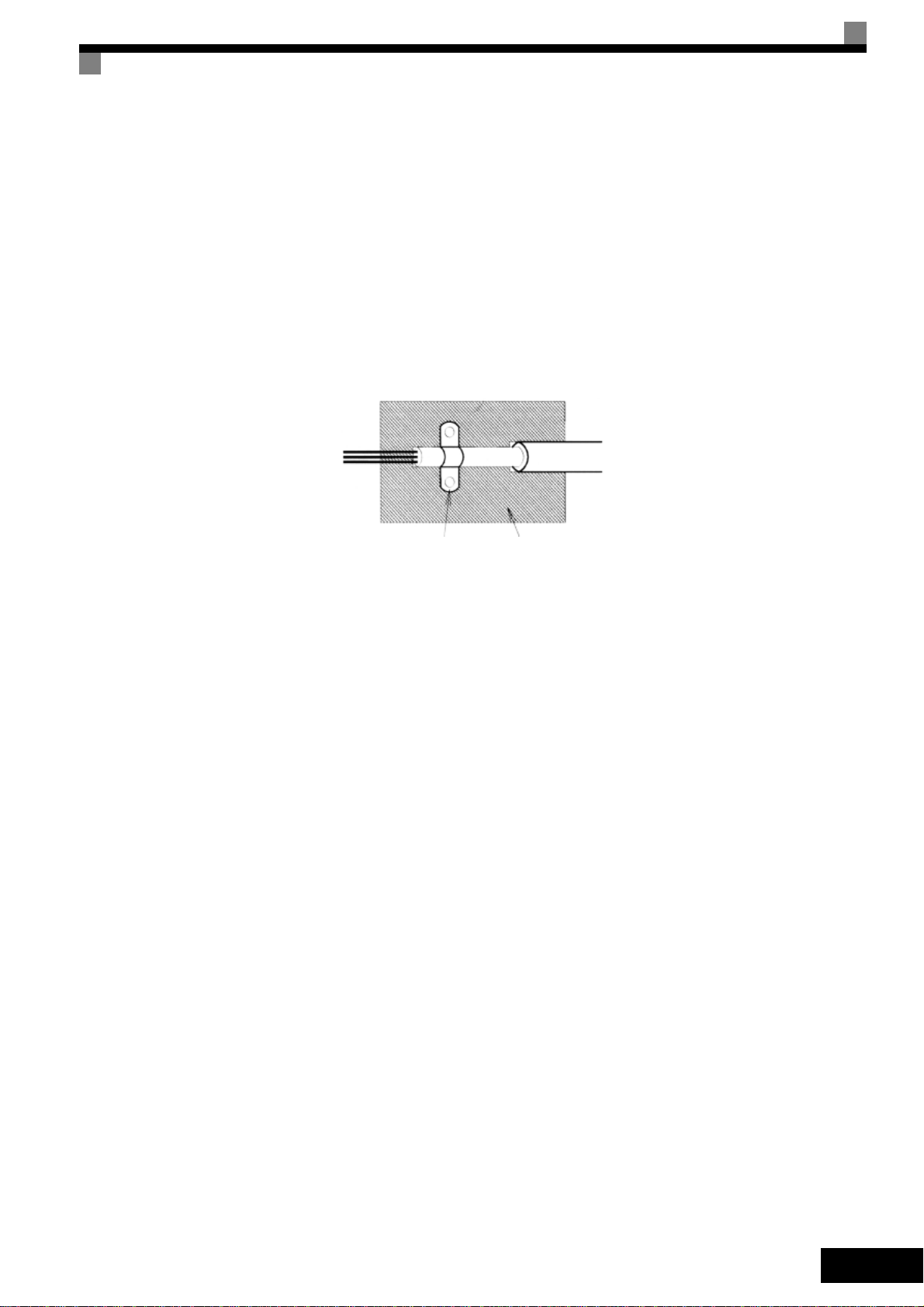
Shielded Cable:
• Use a cable with braided shield.
• Ground the maximum possible area of the shield. It is advisable to ground the shield by connect-
ing the cable to the ground plate with metal clips (see following figure).
Ground Clip
Fig 1 Earthing the cable shield with metal clips
The grounding surfaces must be highly conductive bare metal. Remove any coats of varnish and
paint.
– Ground the cable shields at both ends.
– Ground the motor of the machine.
Ground Plate
EN-5

Installation
Mechanical Installation
Unpacking the Inverter
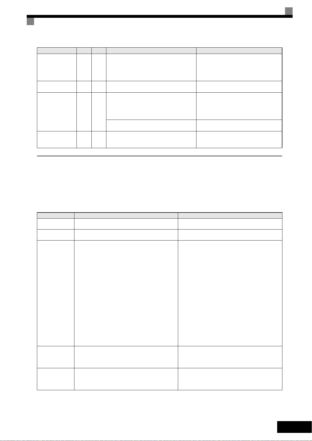
Check the following items after unpacking the inverter.
Item Method
Has the correct Inverter model been
delivered?
Is the Inverter damaged in any way?
Are any screws or other components
loose?
If any irregularities in the above items are found, contact the agency from which the Inverter was purchased or your Omron Yaskawa Motion Control representative immediately.
Checking the Installation Site
Protection covers are attached to the top and bottom of the NEMA 1 / IP20 Inverters. Be sure to
remove the top cover before operating a 200 or 400 V Class Inverter with a capacity of 18.5 kW or
less inside a panel.
Observe the following precautions when mounting the Inverter:
• Install the Inverter in a clean location which is free from oil mist and dust. It can be installed in a
totally enclosed panel that is completely shielded from floating dust.
• When installing or operating the Inverter, always take special care so that metal powder, oil,
water, or other foreign matter does enter the Inverter.
• Do not install the Inverter on combustible material, such as wood.
• Install the Inverter in a location free from radioactive materials and combustible materials.
• Install the Inverter in a location free from harmful gasses and liquids.
• Install the Inverter in a location without excessive oscillation.
• Install the Inverter in a location free from chlorides.
• Install the Inverter in a location without direct sunlight.
Check the model number on the nameplate on the side of the
Inverter.
Inspect the entire exterior of the Inverter to see if there are any
scratches or other damage resulting from shipping.
Use a screwdriver or other tools to check for tightness.
EN-6
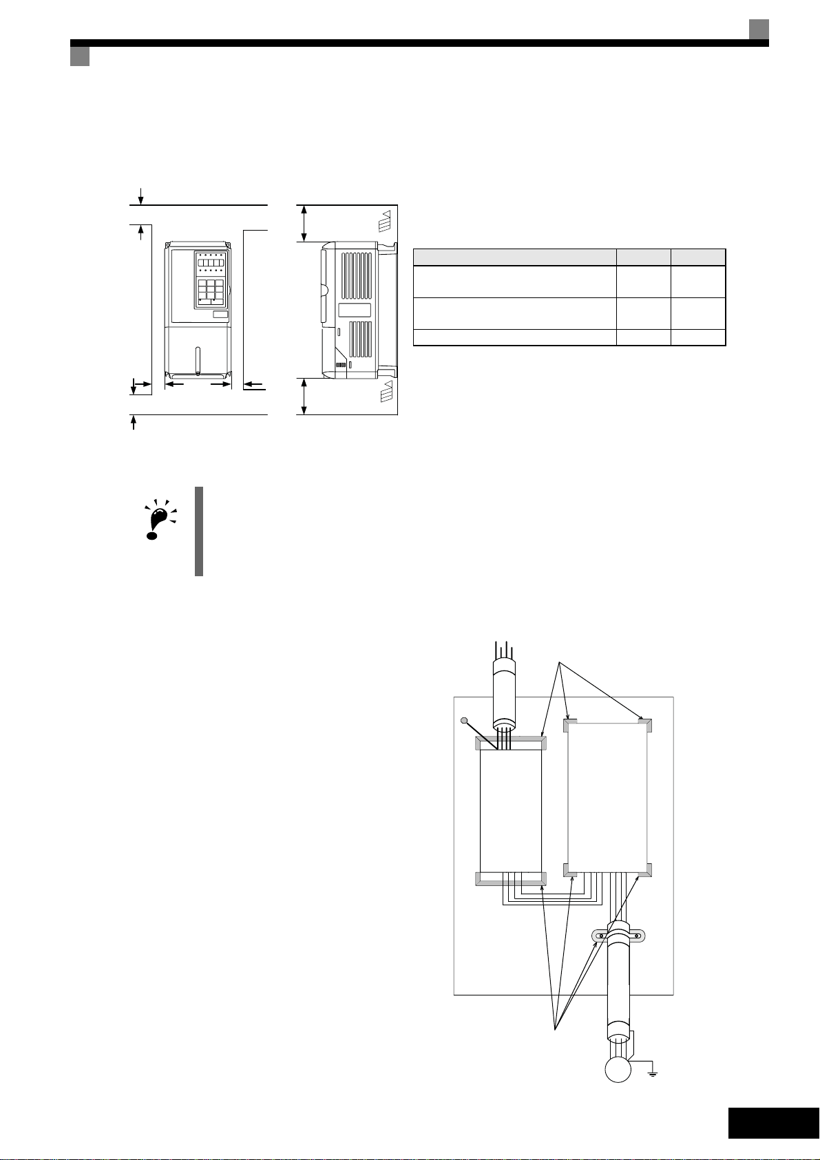
Installation Orientation
Install the Inverter vertically so as not to reduce the cooling effect. When installing the Inverter,
always provide the following installation space to allow normal heat dissipation.
A
30mm min.
50mm
min.
Horizontal Space
30mm min.
B
Air
120mm min.
Air
Vertical Space
Fig 2 Installation space
1. The same space is required horizontally and vertically for IP00, IP20 and NEMA 1 Inverters.
2. Always remove the top protection cover after installing an Inverter with an output of 18.5 kW or less in a
panel.
IMPORTANT
IMPORTANT
Always provide enough space for suspension eye bolts and the main circuit lines when installing an
Inverter with an output of 22 kW or more in a panel.
Installation of Inverters and EMC filters
For an EMC rules compliant installation
consider the following points:
• Use a line filter.
• Use shielded motor cables.
• Mount the inverter and filter on a
grounded cunductive plate.
• Remove any paint or dirt before mount-
ing the parts in order to reach the lowest possible grounding impedance.
A B
200V class inverter, 0.55 to 90 kW
400V class inverter, 0.55 to 132 kW
200V class inverter, 110 kW
400V class inverter, 160 to 220 kW
50 mm 120 mm
120 mm 120 mm
400V class inverter, 300 kW 300 mm 300 mm
PEL1L2
L3
Ground Bonds
Remove any paint!
PE
Line
Inverter
Filter
Fig 3 EMC filter installation
Cable Lenght
as short as possible
Grounded
Metal Plate
Load
GND
Ground Bonds
Remove any paint!
L2
V
GND
W
U
L1
L3
Screened
Motor cable
M
~3
EN-7
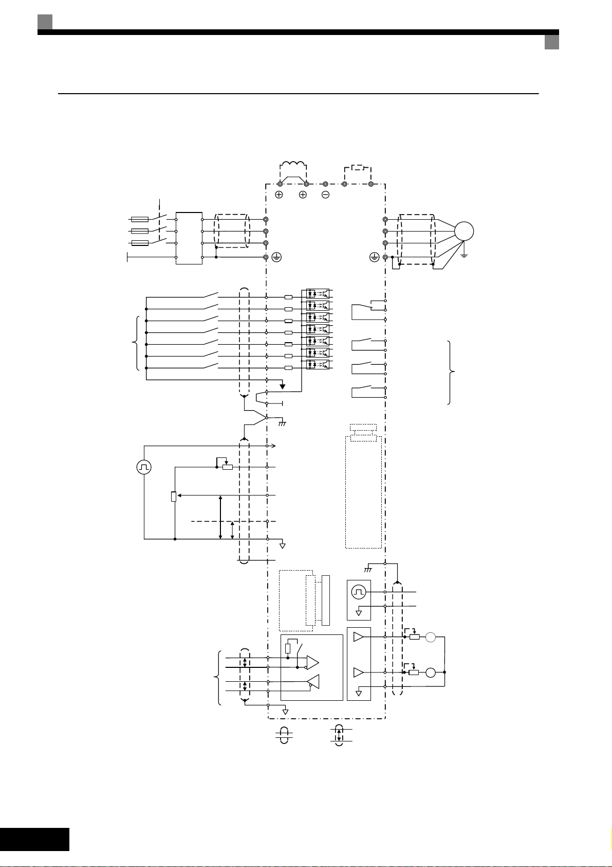
Electrical Connection
Wiring the Inverter
Main Contactor
T
Fuses
PE
L1
L2
L3
Line
Filter
3-phase power
380 to 480 V
50/60 Hz
DC reactor to improve input
power factor (optional)
Short-circuit bar
R/L1
S/L2
T/L3
2
Varispeed F7
Braking resistor unit (optional)
1
B1
B2
U/T1
V/T2
W/T3
M
Multi-function
digital inputs
[Factory setting]
Forward Run / Stop
Reverse Run / Stop
External Fault
Fault reset
Multi-step speed setting 1
Multi-step speed setting 2
Jog frequency selection
Analog input setting
adjustment
0 to 10 V
2 k
Ω
4 to 20 mA
MEMOBUS
communication
RS-485/422
S1
S2
S3
S4
S5
S6
S7
SN
SC
SP
24 V
E(G)
Shield
terminal
Pulse train input [Default:
RP
Frequency reference input]
0 to 32 kHz
+V
Analog input power supply
Ω
2 k
PP
15 V, 20 mA
Analog input 1: Master
A1
frequency reference
0 to 10 V (20 k
Multi-function analog input 2
A2
[Default: Frequency bias
4 to 20 mA (20 k
AC
-V
Analog input power supply
-15 V, 20 mA
Ω)
Ω)]
0 V
Input
Option
Card
R+
P
R-
S+
P
S-
IG
2CN
Terminating
resistance
Option
Shield
terminal
2CN
PG
Card
MA
Fault relay output
MB
250 VAC, 1 A max.
30 VDC, 1 A max.
MC
M1
M2
M3
M4
M5
Relay output 3
[Default:
M6
Frequency agree 1]
E(G)
MP
AC
FM
AM
AC
Relay output 1
[Default: Running]
Relay output 2
[Default: Zero speed]
Pulse train output
0 to 32 kHz (2.20 k
[Default: Output frequency]
Adjustment,
20 k
Ω
+
FM
Adjustment,
20 k
Ω
+
AM
Multi-function digital output
250 VAC, 1 A max.
30 VDC, 1 A max.
Ω)
-
Multi-function analog output 1
(-10 to +10 V, 2 mA / 4 to 20 mA)
[Default: Output frequency, 0 to 10 V)
4 to 20 mA (20 k
-
Multi-function analog output 2
(-10 to +10 V, 2 mA / 4 to 20 mA)
[Default: Output current, 0 to 10 V)
4 to 20 mA (20 k
Ω)]
Ω)]
EN-8
Shielded
wires
Fig 4 Wiring Diagram
Twisted-pair
P
shielded wires
Main Circuit Terminals
Main circuit terminal functions are summarized according to terminal symbols in Ta b l e 1 . Wire the
terminals correctly for the desired purposes.
Table 1 Main Circuit Terminal Functions (200 V Class and 400 V Class)
Purpose Terminal Symbol
Main circuit power input
Inverter outputs U/T1, V/T2, W/T3 20P4 to 2110 40P4 to 4300
DC bus terminals
Braking Resistor Unit Connec-
tion
DC reactor connection
Braking Unit connection
Ground 20P4 to 2110 40P4 to 4300
R/L1, S/L2, T/L3 20P4 to 2110 40P4 to 4300
R1/L11, S1/L21, T1/L31 2022 to 2110 4022 to 4300
1,
B1, B2 20P4 to 2018 40P4 to 4018
1, 2
3,
Model: CIMR-F7Z
200 V Class 400 V Class
20P4 to 2110 40P4 to 4300
20P4 to 2018 40P4 to 4018
2022 to 2110 4022 to 4300
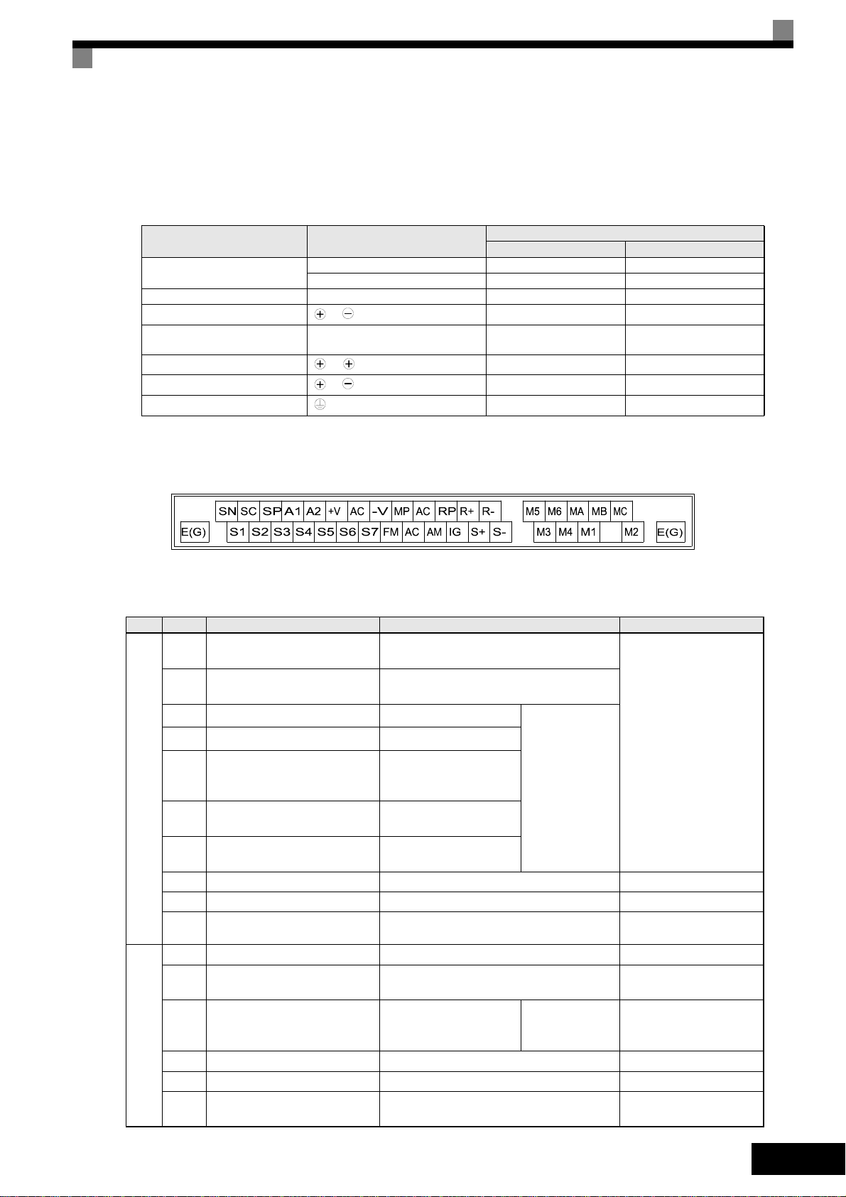
Control Circuit Terminals
Fig 5 shows the control terminal arrangement. The functions of the control circuit terminals are
shown in Tabl e 2 . Use the appropriate terminals for the correct purposes.
Fig 5 Control terminal arrangement
Table 2 Control Circuit Terminals with default settings
Ty p e No. Signal Name Function Signal Level
S1 Forward run/stop command
S2 Reverse run/stop command
S3
External fault input
S4
Fault reset
*1
Multi-step speed reference 1
*1
S5
(Master/auxiliary switch)
Multi-step speed reference 2
S6
Digital input signals
*1
S7
Jog frequency reference
*1
Forward run when ON; stopped when
OFF.
Reverse run when ON; stopped when
OFF.
Fault when ON.
Reset when ON
Auxiliary frequency reference when ON.
Multi-step speed 2
when ON.
Jog frequency when
*1
ON.
Functions are
selected by setting H1-01 to
H1-05.
24 VDC, 8 mA
Photocoupler isolation
SC Digital input common – –
SN Digital Input Neutral – –
SP Digital Input Power Supply +24VDC power supply for digital inputs
24 VDC, 250 mA max.
*2
+V 15 V power output 15 V power supply for analog references 15 V (Max. curr.: 20mA)
A1 Frequency reference 0 to +10 V/100%
Auxiliary Frequency Refer-
A2
ence
Auxiliary analog frequency reference;
4 to 20 mA (250Ω)
Function is
selected by setting H3-09.
–10 to +10 V (20 kΩ)
0 to +10 V (20 kΩ)
4 to 20 mA (250 Ω)
0 V to +10 V (20 kΩ)
0 to 20 mA (250 Ω)
-V –15 V power output –15 V power supply for analog references
AC Analog reference common – –
Analog input signals
Shield wire, optional ground
E(G)
line connection point
––
EN-9
Ty p e No. Signal Name Function Signal Level
M1
During run (NO) Closed during Run
M2
M3
M4
M5
M6
MA
Digital output signals
MB
Zero speed (NO)
Speed agreement detection
(NO)
Fault output signal
Closed when output
frequency at zero level
(b2-01) or below
Within ± 2 Hz of set frequency when ON
Closed across MA and MC during faults
Open across MB and MC during faults
Function
selected by
H2-01 to H2-03
Relay contacts
Contact capacity:
1 A max. at 250 VAC
1 A max. at 30 VDC
MC
FM Output frequency
AC Analog common –
AM Inverter output power
Analog output signals
Analog output frequency signal;
0 to 10 V; 10V=FMAX
Analog output power
signal;
0 to 10V; 10V=max.
appl. motor capacity
Function
selected by
H4-01
Function
selected by
H4-04
0 to +10 V max. ±5%
2 mA max.
–10 to +10 V max. ±5%
2 mA max
4 to 20 mA
0 to 32 kHz (3kΩ)
*4
RP Pulse Input
H6-01 (Frequency reference input)
High level voltage 3.5 to
13.2 V
Pulse I/O
MP Pulse Output H6-06 (Output frequency)
R+
MEMOBUS communications
input
R-
S+
MEMOBUS communications
output
S-
RS-485/422
For 2-wire RS-485, short R+ and S+
as well as R- and S-.
0 to 32 kHz
+15 V output (2.2kΩ)
Differential input,
PHC isolation
Differential input,
PHC isolation
IG Signal common – –
*1. The default settings are given for terminals S3 to S7. For a 3-wire sequence, the default settings are a 3-wire sequence for S5, multi-
step speed setting
1 for S6 and multi-step speed setting 2 for S7.
*2. Do not use this power supply for supplying any external equipment.
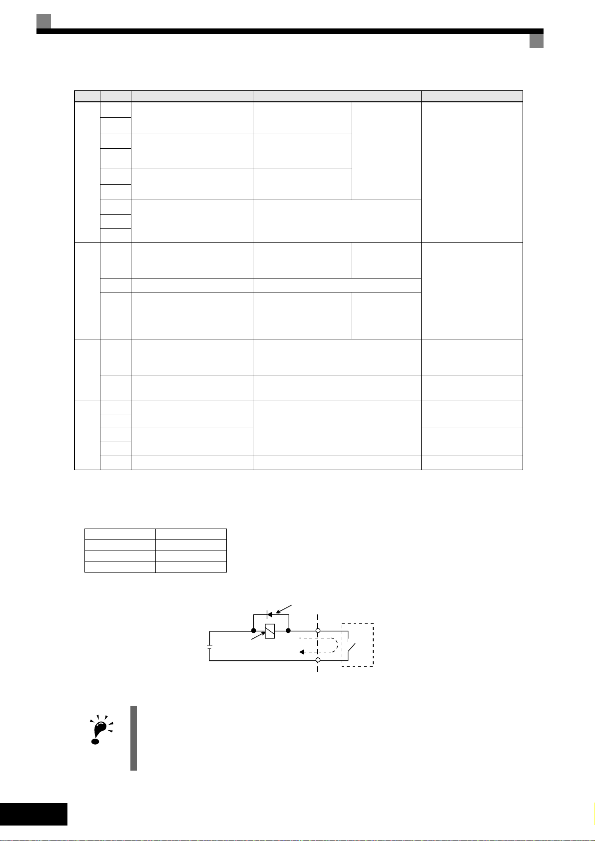
*3. When driving a reactive load, such as a relay coil with DC power supply, always insert a flywheel diode as shown in Fig 6
*4. Pulse input specifications are given in the following table:
Low level voltage 0.0 to 0.8 V
High level voltage 3.5 to 13.2 V
H duty 30% to 70%
Pulse frequency 0 to 32 kHz
*3
EN-10
IMPORTANT
Flywheel diode
The rating of the flywheel diode must
External power:
30 VDC max.
Coil
1 A max.
be at least as high as the circuit voltage.
Fig 6 Flywheel Diode Connection
1. In Fig 4 the wiring of the digital inputs S1 to S7 is shown for the connection of contacts or NPN transistors (0V common and sinking mode). This is the default setting.
For the connection of PNP transistors or for using a 24V external power supply, refer to Ta b l e 3 .
2. A DC reactor is an option only for Inverters of 18.5 kW or less. Remove the short circuit bar when connecting a DC reactor.
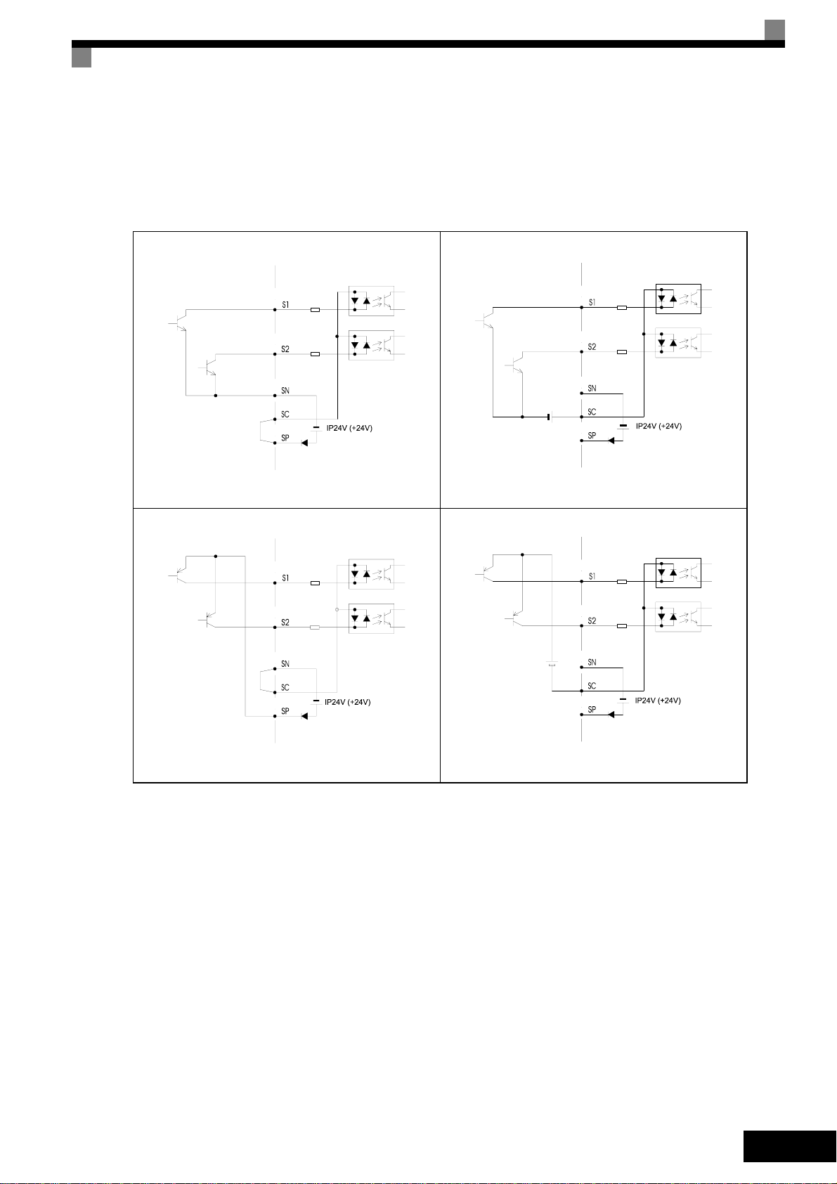
Sinking/Sourcing Mode (NPN/PNP Selection)
Int
(PNP)
Ext
(PNP)
The input terminal logic can be switched over between sinking mode (0-V common, NPN) and
sourcing mode (+24V common, PNP) by using the jumper CN5. An external power supply is also
supported, providing more freedom in signal input methods.
Table 3 Sinking / Sourcing Mode and Input Signals
Internal Power Source - Sinking Mode (NPN)
ernal Power Source - Sourcing Mode
External Power Source - Sinking Mode (NPN)
External +24 V
ernal Power Source - Sourcing Mode
External +24 V
EN-11

Wiring Main Circuit Inputs
Installing Fuses
To protect the inverter, it is recommended to use semiconductor fuses like they are shown in the
table below.
Table 4 Input Fuse Selection
Rated Inverter
Inverter Type
20P4 3.2 240 10 12~25 A60Q12-2 600V / 12A 17
20P7 4.1 240 10 12~25 A60Q12-2 600V / 12A 17
21P5 7.0 240 15 23~55 A60Q15-2 600V / 15A 26
22P2 9.6 240 20 34~98 A60Q20-2 600V / 20A 41
23P7 15 240 30 82~220 A60Q30-2 600V / 30A 132
25P5 23 240 40 220~610 A50P50-4 500V / 50A 250
27P5 31 240 60 290~1300 A50P80-4 500V / 80A 640
2011 45 240 80 450~5000 A50P80-4 500V / 80A 640
2015 58 240 100 1200~7200 A50P125-4 500V / 125A 1600
2018 71 240 130 1800~7200 A50P150-4 500V / 150A 2200
2022 85 240 150 870~16200 A50P150-4 500V / 150A 2200
2030 115 240 180 1500~23000 A50P200-4 500V / 200A 4000
2037 145 240 240 2100~19000 A50P250-4 500V/ 250A 6200
2045 180 240 300 2700~55000 A50P300-4 500V / 300A 9000
2055 215 240 350 4000~55000 A50P350-4 500V / 350A 12000
2075 283 240 450 7100~64000 A50P450-4 500V / 450A 20000
2090 346 240 550 11000~64000 A50P600-4 500V / 600A 36000
2110 415 240 600 13000~83000 A50P600-4 500V / 600A 36000
Output
Current (A)
Voltage (V) Current (A)
Fuse Selection Selection Example (Ferraz)
I2t (A2s)
Model Rating
I2t (A2s)
40P4 1.8 480 5 6~55 A60Q10-2 600V / 10A 10
40P7 2.1 480 5 6~55 A60Q10-2 600V / 10A 10
41P5 3.7 480 10 10~55 A60Q12-2 600V / 12A 17
42P2 5.3 480 10 18~55 A60Q15-2 600V / 15A 26
43P7 7.6 480 15 34~72 A60Q20-2 600V / 20A 41
44P0 8.7 480 20 50~570 A60Q30-2 600V / 30A 132
45P5 12.5 480 25 100~570 A60Q30-2 600V / 30A 132
47P5 17 480 30 100~640 A60Q30-2 600V / 30A 132
4011 24 480 50 150~1300 A70P50-4 700V / 50A 300
4015 31 480 60 400~1800 A70P70-4 700V / 70A 590
4018 39 480 70 700~4100 A70P80-4 700V / 80A 770
4022 45 480 80 240~5800 A70P80-4 700V / 80A 770
4030 60 480 100 500~5800 A70P100-4 700V / 100A 1200
4037 75 480 125 750~5800 A70P125-4 700V / 125A 1900
4045 91 480 150 920~13000 A70P150-4 700V / 150A 2700
4055 112 480 150 1500~13000 A70P200-4 700V / 200A 4800
4075 150 480 250 3000~55000 A70P250-4 700V / 250A 7500
4090 180 480 300 3800~55000 A70P300-4 700V / 300A 11000
4110 216 480 350 5400~23000 A70P350-4 700V / 350A 15000
4132 260 480 400 7900~64000 A70P400-4 700V / 400A 19000
4160 304 480 450
4185 370 480 600
4220 506 480 700
4300 675 480 900
14000~250000
20000~250000
34000~400000
52000~920000
A70P450-4 700V / 450A 24000
A70P600-4 700V / 600A 43000
A70P700-4 700V / 700A 59000
A70P900-4 700V / 900A 97000
Consider the following precautions for the main circuit power supply input.
• If a moulded case circuit breaker is used for the power supply connection (R/L1, S/L2, and T/L3),
ensure that the circuit breaker is suitable for the Inverter.
• If an earth leakage breaker is used, it should be able to detect all kinds of current in order to
ensure a safe earth leakage current detection
EN-12

• A magnetic contactor or other switching device can be used at the inverter input. The inverter
should not be powered up more than once per hour.
• The input phases (R/S/T) can be connected in any sequence.
• If the Inverter is connected to a large-capacity power transformer (600 kW or more) or a phase
advancing capacitor is switched nearby, an excessive peak current could flow through the input
power circuit, causing an inverter damage. As a countermeasure install an optional AC Reactor
at the inverter input or a DC reactor at the DC reactor connection terminals.
• Use a surge absorber or diode for inductive loads near the Inverter. Inductive loads include mag-
netic contactors, electromagnetic relays, solenoid valves, solenoids, and magnetic brakes.
Wiring the Output Side of the Main Circuit
The following precautions should be considered for the output circuit wiring.
• Never connect any power source to the inverter output terminals. Otherwise the inverter can be
damaged.
• Never short or ground the output terminals. Otherwise the inverter can be damaged.
• Do not use phase correction capacitors. Otherwise the inverter and capacitors can be damaged.
• Check the control sequence to make sure, that the magnetic contactor (MC) between the Inverter
and motor is not turned ON or OFF during inverter operation. If the MC is turned ON during the
Inverter is operation, a large inrush current will be created and the inverter’s overcurrent protection may operate.
Ground Connection
The following precautions should be considered for the ground connection.
• Do not share the ground wire with other devices, such as welding machines or power tools.
• Always use a ground wire, that complies with technical standards on electrical equipment and
minimize the length of the ground wire.
Leakage current is caused by the Inverter. Therefore, if the distance between the ground electrode and the ground terminal is too long, potential on the ground terminal of the Inverter will
become unstable.
• When more than one Inverter is used, do not to loop the ground wire.
OK
Fig 7 Ground Wiring
NO
Control Circuit Wiring Precautions
Consider the following precautions for wiring the control circuits.
• Separate control circuit wiring from main circuit wiring (terminals R/L1, S/L2, T/L3, B1, B2, U/T1,
V/T2, W/T3, B1, B2, , 1, 2, and 3, PO, NO) and other high-power lines.
• Separate wiring for control circuit terminals MA, MB, MC, M1 to M6 (relay outputs) from wiring to
other control circuit terminals.
• If an optional external power supply is used, it should be a UL Listed Class 2 power supply.
• Use twisted-pair or shielded twisted-pair cables for control circuits to prevent operating faults.
• Ground the cable shields with the maximum contact area of the shield and ground.
• Cable shields have to be grounded on both cable ends.
EN-13
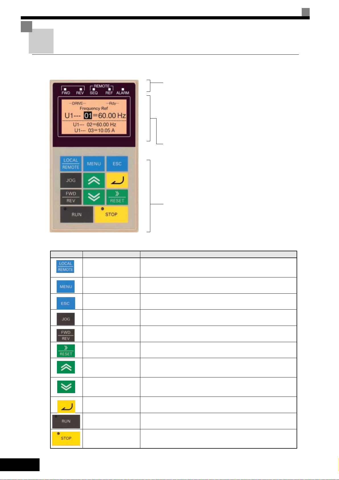
Keypad Operation
Digital Operator Display (optional)
The key names and functions of the Digital Operator are described below
Drive Mode Indicators
FWD: Lights up when a forward run command is
REV: Lights up when a reverse run command is
SEQ: Lights up when any other run command
REF: Lights up when any other frequency reference
ALARM: Lights up when an error or alarm has
Data Display
Displays monitor data, parameter numbers, and settings.
Mode Display (displayed at the upper left of the data display
DRIVE: Lights up in Drive Mode.
QUICK: Lights up in Quick Programming Mode.
ADV: Lights up in Advanced Programming Mode.
VERIFY: Lights up in Verify Mode.
A. TUNE: Lights up in Autotuning Mode.
input.
input.
source than the Digital Operator is selected.
source than the Digital Operator is selected.
occurred.
Digital Operator Keys
Key Name Function
LOCAL/REMOTE Key
MENU Key Selects the modes.
ESC Key Returns to the status before the DATA/ENTER Key was pressed.
JOG Key
FWD/REV Key
Shift/RESET Key
Increment Key
Decrement Key
Keys
Execute operations such as setting user parameters,
monitoring, jogging, and autotuning.
Switches between operation via the Digital Operator (LOCAL) and
the settings in b1-01 and b1-02 (REMOTE).
This key can be enabled or disabled by setting parameter o2-01.
Enables jog operation when the Inverter is being operated from the
Digital Operator.
Selects the rotation direction of the motor when the Inverter is being
operated from the Digital Operator.
Sets the active digit when programming user parameters.
Also acts as the Reset key when a fault has occurred.
Selects user parameter numbers and increments parameter settings.
Used to move to the next item or data.
Selects user parameter numbers and decrements parameter settings.
Used to move to the previous item or data.
EN-14
DATA/ENTER Key Enters menus and parameters and validates parameter settings.
RUN Key
STOP Key
Starts operation when the Inverter is being controlled by the Digital
Operator (LOCAL Mode).
Stops Inverter operation (LOCAL and REMOTE Mode).
This key can be enabled or disabled when operating from a source
different tan the operator by setting parameter o2-02.
Power Up and Basic Parameter Setup
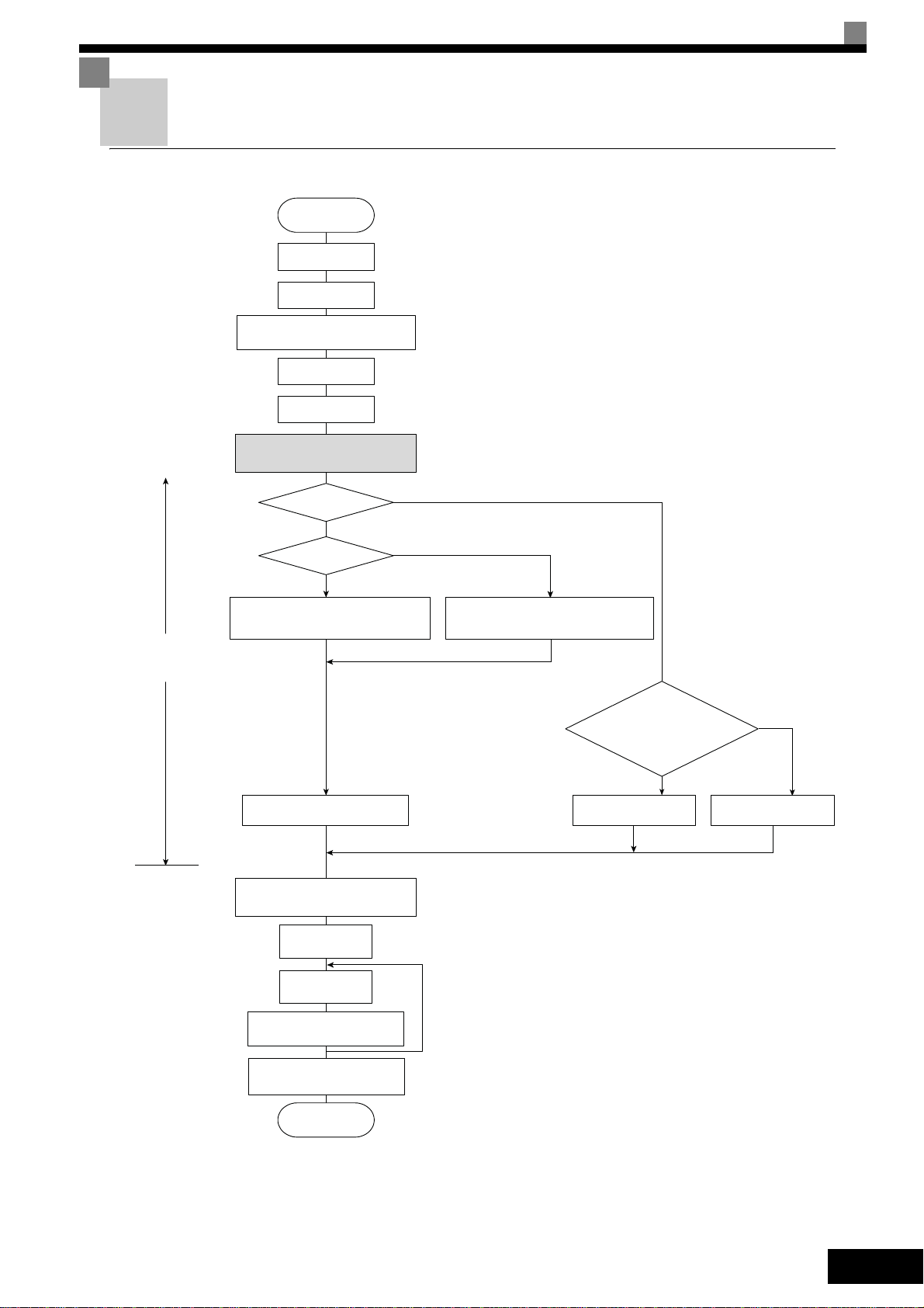
Start Up Procedure
START
Installation
Wiring
Set power supply
voltage jumper *1
Turn ON power
Confirm status
Select control
method.
Settings according
to control mode
Basic settings
(Quick programming mode)
V/f control
YES
PG?
NO
V/f control
Set E1-03.
V/f default: 200V/50Hz (400V/50Hz)
Non-rotating autotuning
for line-to-line resistance
Application settings
(Advanced programming mode)
No-load
operation
Loaded
operation
Optimum adjustments
and parameter settings
Check/record
parameter settings
END
NO
YES
Vector Control (A1-02 = 2 or 3) *5
V/f Control with PG (A1-02 = 1
Set E1-03, E2-04 and F1-01. *2
V/f default: 200V/50Hz (400V/50Hz)
Motor
operation possible
during autotuning?
*3
YES
*4
Rotating
autotuning
*6
NO
Non-rotating
autotuning
*6
1.Set for 400 V Class Inverter for 75 kW or more.
2.If there is a reduction gear between the motor and PG, set the
reduction ratio in F1-12 and F1-13 in advanced programming
mode.
3.Use rotational autotuning to increase autotuning accuracy
whenever it is okay for the motor to be operated.
4.If the motor cable changes to 50 m or longer for the actual
installation, perform non-rotating autotuning for the line-to-line
resistance only on site.
5.The default control mode is Open Loop Vector control
(A1-02=2).
6.If the maximum output frequency and the base frequency are
different, set the maximum output frequency (E1-04) after
autotuning.
Fig 8 Trial Operation Flowchart
EN-15

Before Power Up
The following points should be checked carefully before the power is switched on.
• Check if the power supply meets the inverter specification.
• Check if the power supply cables are tightly connected to the right terminals (L1, L2, L3).
• Check if the motor cables are tightly connected to the right terminals on the inverter side (U, V,
W) as well as on the motor side.
• Check if the braking unit / braking resistor is connected correctly.
• Check if the Inverter control circuit terminal and the control device are wired correctly.
• Set all Inverter control circuit terminals to OFF.
• When a PG card is used, check if it is wired correctly.
Display after Power Up
After normal power up without any problems the operator display shows the following messages
Display for normal
operation
-DRIVE-
Frequency Ref
U1- 01=50.00Hz
U1-02=50.00Hz
U1-03=10.05A
Rdy
The frequency reference monitor is displayed in the data display section.
When a fault has occurred or an alarm is active a fault or alarm message will appear. In this case,
refer to page 21, Troubleshooting.
Display for fault operation
-DRIVE-
UV
DC Bus Undervolt
A fault or alarm message is shown on the
display.
The example shows a low voltage alarm.
Autotuning
Autotuning sets motor parameters automatically when using Open Loop or Closed Loop Vector control, when the cable length is long or the installation has changed.
Setting the Autotuning Mode
One of the following three autotuning modes can be set.
• Rotating autotuning
• Non-rotating autotuning
• Non-rotating autotuning for line-to-line resistance only
EN-16
Rotating Autotuning (T1-01 = 0)
Rotating autotuning is used for Open Loop and Closed Loop Vector control only. Set T1-01 to 0,
input the data from the motor nameplate, and then press the RUN key on the Digital Operator. The
Inverter will operate the motor for approximately 1 minute and set the required motor parameters
automatically.
Non-rotating Autotuning (T1-01 = 1)
Non-rotating autotuning is used for Open Loop and Closed Loop Vector control only. Set T1-01 to 1,
input the data from the motor nameplate, and then press the RUN key on the Digital Operator. The
inverter will supply power to the non-rotating motor for approximately 1 minute and some of the

motor parameters will be set automatically. The remaining motor parameters will be set automatically during the first time operation.
Non-rotating Autotuning for Line-to-Line Resistance (T1-01 = 2)
Non-rotating autotuning for line-to-line resistance can be used in any control mode. This is the only
possible autotuning for V/f control and V/f control with PG.
It can be used to improve the performance when the motor cable is long, the cable length has
changed or when the motor and inverter have different capacities.
To perform autotuning in V/f control or V/f control with PG, set T1-02 (Motor rated power) and T1-04
(Motor rated current) and then press the RUN key on the Digital Operator. The Inverter will supply
power to the non-rotating motor for approximately 20 seconds and the Motor line-to-line resistance
and cable resistance will be automatically measured.
1. Power will be supplied to the motor during autotuning but the motor will not turn. Do not touch the motor
until autotuning has been completed.
IMPORTANT
2. Ensure that all motor contactors are closed before the autotuning is started.
3. To cancel autotuning press the STOP key on the Digital Operator.
Other Alarms and Faults During Autotuning
For an overview of possible autotuning alarms or faults and corrective actions refer to page 24, Auto-
tuning Faults.
EN-17
User Parameter
Param-
eter
Num-
ber
Name Description
Initialize Data
Language
selection for
Digital Opera-
A1-00
tor display(JVOP160-OY only)
Parameter
A1-01
access level
Control method
A1-02
selection
A1-03 Initialize
0:English
2:German
3:French
4:Italian
5:Spanish
6:Portuguese
0:Monitoring only (Monitoring drive
mode and setting A1-01 and A1-04.)
1:Used to select user parameters (Only
parameters set in A2-01 to A2-32 can
be read and set.)
2:Advanced
(Parameters can be read and set in
both, quick programming mode (Q)
and advanced programming mode
(A).
0:V/f control
1:V/f control with PG
2:Open loop vector control
3:Closed loop vector control
0: No initializing
1110: Initializes using the user
parameters
2220: Initializes using a two-wire
sequence. (Initializes to the
factory setting.)
3330: Initializes using a three-wire
sequence.
Sequence / Reference Source
Sets the frequency reference input
method.
0:Digital Operator
1:Control circuit terminal (analog input)
2:Serial communication (RS422 / 485)
3:Option Card
Sets the run command input method.
0:Digital Operator
1:Control circuit terminal (digital inputs)
2:Serial communication (RS422 / 485)
3:Option Card
Selects the stopping method when the
Run signal is removed
0:Deceleration to stop
1:Coast to stop
2:DC injection to stop
3:Coast to stop with timer (New Run
commands are disregarded while
coasting.)
0:Reverse enabled
1:Reverse disabled
2:Output Phase Rotation (both rota-
tional directions are enabled)
3:Output Phase Rotation with Reverse
disabled.
b1-01
b1-02
b1-03
b1-04
Reference
source selection
RUN command source
selection
Stopping
method selection
Prohibition of
reverse operation
Acceleration / Deceleration Settings
C1-
Acceleration/
Deceleration
times
Sets the time to accelerate/decelerate
from 0 Hz to the maximum output frequency.
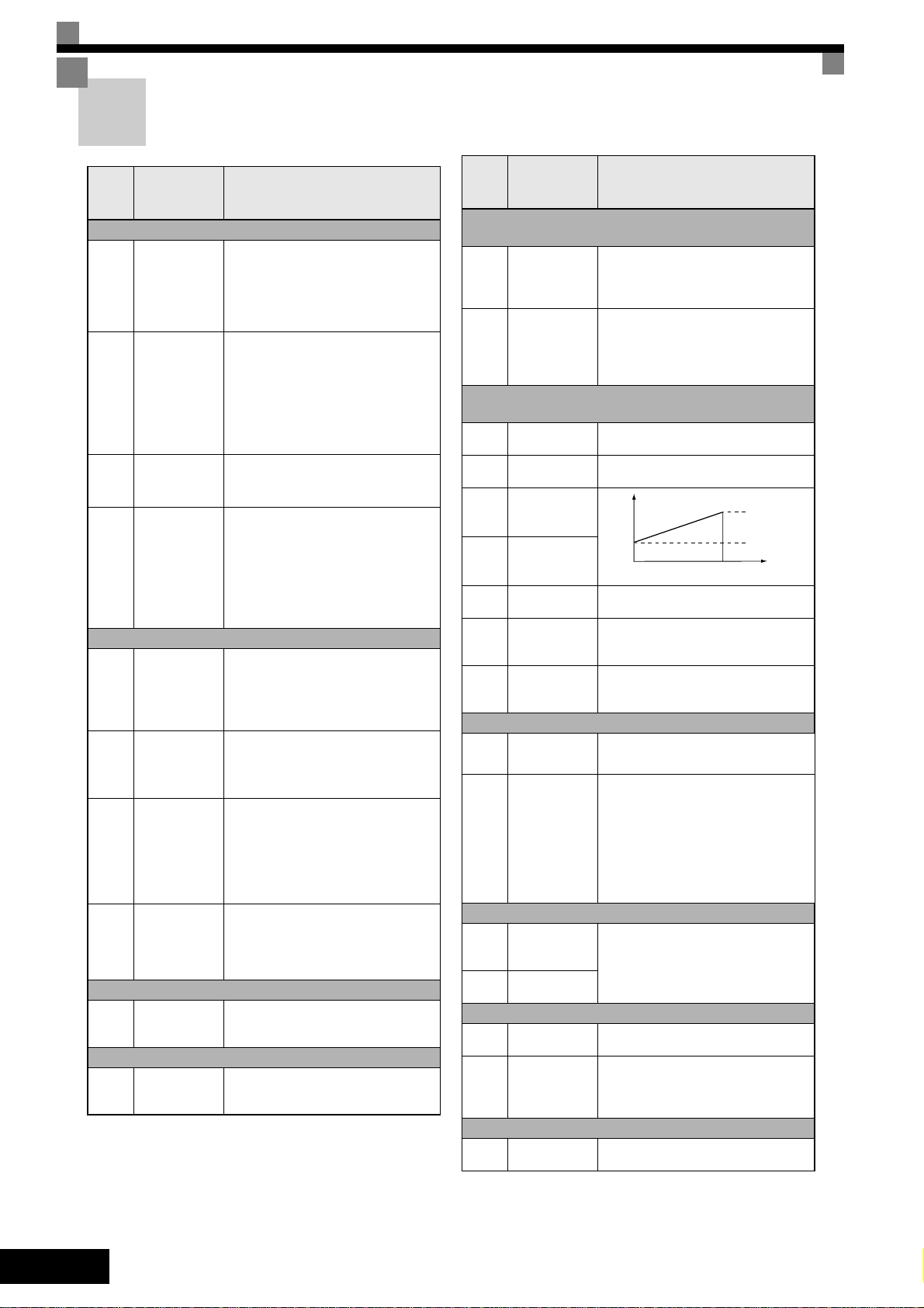
S-Curve Settings
C2-
S-curve characteristic time
at acceleration
Sets the S-curve characteristic at acceleration start and end.
Param-
eter
Num-
ber
Name Description
Motor Slip Compensation (not available in V/f with
PG)
Used to improve speed accuracy
• Increase if output frequency is too low
• Decrease if output frequency is too
high.
Sets the slip compensation delay time
• Increase if output frequency is not
stable
• Decrease setting when slip compensation responsiveness is low.
C3-01
C3-02
Slip compensation gain
Slip compensation delay time
(only available
in V/f and OLV)
Speed Control (ASR) (only available in V/f with PG
and CLV)
C5-01
C5-02
C5-03
C5-04
C5-06
C5-07
C5-08
ASR proportional gain 1
ASR integral
time 1
ASR proportional gain 2
ASR integral
time 2
ASR delay time
(only CLV)
ASR switching
frequency
(only CLV)
ASR integral
limit
(only CLV)
Sets the proportional gain of the speed
loop (ASR)
Sets the integral time of the speed loop
(ASR)
P,I
0 E1-04
Sets the ASR filter time constant.
Sets the frequency for switching
between ASR gain 1, 2 and ASR integral
time 1, 2
Sets the limit for the integral part of the
ASR controller.
P=C5-01
I=C5-02
P=C5-03
I=C5-04
Motor
speed (Hz)
Carrier Frequency
C6-01
C6-02
Heavy/Normal
duty selection
Carrier frequency selection
0:Heavy Duty
1:Normal Duty 1
2:Normal Duty 2
Selects the carrier frequency (factory
setting depends on Inverter capacity)
0: Low noise, low carrier
1: 2.0 kHz
2: 5.0 kHz
3: 8.0 kHz
4: 10.0 kHz
5: 12.5 kHz
6: 15.0 kHz
F: Programmable pattern
Speed Settings
Multi speed
d1-01
to
references 1 to
d1-16
d1-17
16
Jog frequency
reference
Sets the multi-step speed references.
Torque Control (only available in CLV)
d5-01
d5-06
Torque control
selection
Speed/torque
control switch
over timer
0:Speed control
1:Torque control
Sets the delay from inputting a “speed/
torque control change” signal (by digital
input) until the control is acutally
changed
V/f Pattern Settings
E1-01
Input voltage
setting
This setting is used as a reference value
for protection functions.
EN-18
Param-
eter
Num-
ber
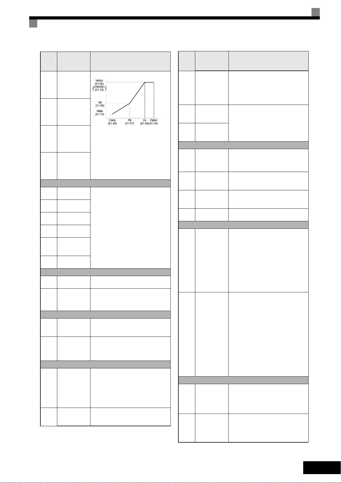
E1-04
E1-05
E1-06
E1-13
Name Description
Max. output
frequency
(FMAX)
Max. output
voltage
(VMAX)
Base frequency (FA)
Base Voltage
(VBASE)
Motor Data Settings
Motor rated
E2-01
current
Motor rated
E2-02
slip
Motor no-load
E2-03
current
Number of
E2-04
motor poles
Motor
E2-09
mechanical
losses
Motor rated
E2-11
output power
PG Option Setup
F1-01 PG constant
F1-05 PG rotation
Digital I/O Settings
Terminal S3 to
H1-01
S7 function
to
H1-05
selection
Terminal M1-
H2-01
M2 and M3-
and
M4 function
H2-02
selection
Analog I/O Settings
Analog input
H3-08
A2 signal level
selection
Analog input
H3-09
A2 function
selection.
Output Voltage (V)
Frequency (Hz)
To set V/f characteristics in a straight
line, set the same values for E1-07
and E1-09. In this case, the setting for
E1-08 will be disregarded.
Always ensure that the four frequencies are set in the following order:
E1-04 (FMAX) ≥ E1-06 (FA) > E1-07
(FB) ≥ E1-09 (FMIN)
Sets the motor data.
Sets the number of PG pulses per
revolution
0:Phase A leads with forward run
command
1:Phase B leads with forward run
command
Refer to page 20, Digital Input Func-
tion Selections (H1-01 to H1-05) for a
list of selections
Refer to page 20, Digital Output Func-
tion Selections for a list of selections
Selects the signal level input at multifunction analog input A2.
0:0 to +10 V (11 bit).
1:-10 to +10 V
2:4 to 20 mA (9-bit input).
Ensure to switch S1-2 to “V” before
using a voltage input.
Selects the multi-function analog
input function for terminal A2.
Param-
eter
Num-
ber
H3-13
H4-01
H4-04
Name Description
Terminal A1/
A2 switching
Terminal FM
monitor selection
Terminal AM
monitor selection
Pulse Train I/O
Pulse train
H6-01
input function
selection
Pulse train
H6-02
input scaling
Pulse train
H6-06
monitor selection
Pulse monitor
H6-07
scaling
Stall Prevention
Stall prevention selection
during accel
L3-01
(not available
in CLV)
Stall preven-
L3-04
tion selection
during decel
Fault Restart
Number of
L5-01
auto restart
attempts
Auto restart
L5-02
operation
selection
Selects on which terminal the main
frequency reference can be input.
0:Use analog input 1 on terminal
A1 for main frequency reference.
1:Use analog input 2 on terminal A2
for main frequency reference.
Sets the number of the monitor
item to be output (U1-) at terminal
FM/AM.
Selects the pulse train input function
0:Frequency reference
1:PID feedback value
2:PID target value
Sets the number of pulses in Hz that
is equivalent to 100% of the input item
selected in H6-01.
Selects the pulse train monitor output
item (U1-)
Sets the number of pulses output in
Hz when the monitor item is 100%.
0:Disabled (Acceleration as set.
With a heavy load, the motor may
stall.)
1:Enabled (Acceleration stopped
when L3-02 level is exceeded.
Acceleration starts again when the
current has fallen below the stall
prevention level).
2:Intelligent acceleration mode (Using
the L3-02 level as a basis, acceleration is automatically adjusted. Set
acceleration time is disregarded.)
0:Disabled (Deceleration as set. If
deceleration time is too short, a
DC bus overvoltage may result.)
1:Enabled (Deceleration is stopped
when the DC bus voltage exceeds
the stall prevention level. Deceleration restarts when the voltage falls
below the stall prevention level
again.)
2:Intelligent deceleration mode
(Deceleration rate is automatically
adjusted so that the Inverter can
decelerate in the shortest possible
time. The set deceleration time is
disregarded.)
3:Enabled with braking resistor
Sets the number of auto restart
attempts.
Automatically restarts after a fault and
conducts a speed search from the run
frequency.
Sets whether a fault relay is activated
during fault restart.
0:No output (Fault relay is not acti-
vated.)
1:Output (Fault relay is activated.)
EN-19
Param-
o
eter
Num-
ber
Name Description
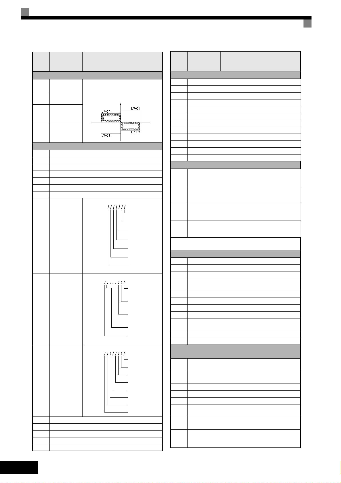
Torque Limit (only OLV and CLV)
L7-01
L7-02
L7-03
L7-04
Forward drive
torque limit
Reverse drive
torque limit
Forward
regenerative
torque limit
Reverse
regenerativ
torque limit
Sets the torque limit vlaue as a percentage of the motor rated torque.
Four individual regions can be set.
Reverse
Output torque
Regen.
Monitor Data
U1-01 Frequency reference in Hz / rpm
U1-02 Output frequency in Hz / rpm
U1-03 Output current in A
U1-06 Output voltage in VAC
U1-07 DC bus voltage in VDC
U1-08 Output power in kW
U1-09 Torque reference
Shows input ON/OFF status.
U1-10 =
Input terminal
U1-10
status
Shows output ON/OFF status.
U1-11 =
Output termi-
U1-11
nal status
Inverter operating status.
U1-12 =
Operation
U1-12
status
U1-13 Cumulative operation time in hrs.
U1-21 ASR input
U1-22 ASR output
U1-34 OPE fault parameter
U1-40 Cooling fan operating time in hrs.
Positive torque
No.
motor
rotations
Regen.
Negative torque
Forward
1: FWD command
(S1) is ON
1: REV command
(S2) is ON
1: Multi input 1
(S3) is ON
1: Multi input 2
(S4) is ON
1: Multi input 3
(S5) is ON
1: Multi input 4
(S6) is ON
1: Multi input 5
(S7) is O N
1: Multi-function
contact output 1
(M1-M2) is ON
1: Multi-function
contact output 2
(M3-M4) is ON
1: Multi-function
contact output 3
(M5-M6) is ON
Not used
(Always 0).
1: Error output
(MA/MB-MC) is ON
Run
1: Zero speed
1: Reverse
1: Reset signal input
1: Speed agree
1: Inverter ready
1: Minor fault
1: Major fault
Param-
eter
Num-
ber
Name Description
Fault Trace Data
U2-01 Current fault
U2-02 Last fault
U2-03 Reference frequency at fault
U2-04 Output frequency at fault
U2-05 Output current at fault
U2-07 Output voltage reference at fault
U2-08 DC bus voltage at fault
U2-09 Output power at fault
U2-11 Input terminal status at fault
U2-12 Output terminal status at fault
U2-13 Operation status at fault
U2-14 Cumulative operation time at fault
Fault History Data
U3-01
to
Last fault to fourth last fault
U3-04
U3-05
to
Cumulative operation time at fault 1 to 4
U3-08
U3-09
to
Fifth last to tenth last fault
U3-14
U3-15
to
Accumulated time of fifth to tenth fault
U3-20
* The following faults are not recorded in the error log:
CPF00, 01, 02, 03, UV1, and UV2.
Digital Input Function Selections (H1-01 to H1-05)
3 Multi-step speed reference 1
4 Multi-step speed reference 2
5 Mulit-step speed reference 3
Jog frequency command (higher priority than multi-
6
step speed reference)
7 Accel/decel time selection 1
F Not used (Set when a terminal is not used)
14 Fault reset (Reset when turned ON)
19 PI control disable
External fault; Input mode: NO contact/NC contact,
20 to
2F
Detection mode: Normal/during operation
71 Speed/torque control change (ON: Torque control)
77 Speed control (ASR) gain switching (ON: C5-03)
Digital Output Function Selections
(H2-01 and H2-02
During run 1 (ON: run command is ON or voltage is
0
being output)
Inverter operation ready; READY: After initialization or
6
no faults
F Not used. (Set when the terminal is not used.)
10 Minor fault (Alarm) (ON: Alarm displayed)
1A During reverse run (ON: During reverse run)
Motor overload (OL1, including OH3) pre-alarm (ON:
1F
90% or more of the detection level)
During torque limit (current limit) (ON: During torque
30
limit)
Activated if the ASR is operating for torque limit. The
32
ASR output becomes the torque reference, the motor
is rotating at the speed limit.
EN-20

Troubleshooting
General Faults and Alarms
Faults and Alarms indicate unsusal inverter / application conditions.
An alarm does not necessarily switch off the inverter but a message is displayed on the keypad (i.e.
a flashing alarm code) and an alarm output can be generated at the multi-function outputs (H2-01
and H2-02) if programmed. An alarm automatically disappears if the alarm condition is not present
anymore.
A fault switches the inverter output off immediately, a message is displayed on the keypad and the
fault output is switched. The fault must be reset manually after the cause and the RUN signal have
been removed.
The following table shows a list of faults and alarms with their corrective actions.
Display
BUS
Option Com Err
CF
Out of Control
CPF00
COM-
ERR(OP&INV)
CPF01
COM-
ERR(OP&INV)
CPF02
BB Circuit Err
CPF03
EEPROM Error
CPF04
INternal A/D Err
DEV
Speed Deviation
EF
External Fault
EF0
Opt External Flt
EFx
Ext Fault Sx
Ext Run Active
Cannot Reset
GF
Ground Fault
Alarm Fault
Meaning Corrective Actions
Option Card Communication Alarm
After initial communication was established, the
connection was lost.
Control Fault
A torque limit was reached continuously for 3
seconds or longer during a deceleration stop in
Open Loop Vector control
Digital Operator Communication Fault 1/2
• Communication fault between Operator and
Inverter
• CPU External RAM Fault
CPF02 Fault
Baseblock circuit error
CPF03
EEPROM error
CPF04
CPU Internal A/D Converter Fault
F1-04 = 0, 1 or 2 and A1-02 = 1 or 3
The speed deviation has been greater than the
setting in F1-10 for a time longer than the setting
F1-11.
F1-04 = 3 and A1-02 = 1 or 3
The speed deviation has been greater than the
setting in F1-10 for a time longer than the setting
F1-11.
Forward/Reverse Run Commands Input
Together
Both the forward and the reverse run commands
are input simultaneously for 500ms or more.
This alarm stops the motor.
External fault input from Communications
Option Card
External fault at terminal Sx (x stands for terminals S3 to S7)
Detected after a fault when a RESET command
is input while the RUN command is still active
Ground Fault
The ground current at the Inverter output
exceeded 50% of the Inverter rated output current and L8-09=1 (Enabled).
Check the connections and all user-side software configurations.
Check the motor parameters
• Disconnect the Digital Operator and then
connect it again.
• Cycle the Inverter power supply.
• Replace the Inverter.
• Perform an initialization to factory defaults.
• Cycle the Inverter power supply.
• Replace the Inverter.
• Reduce the load.
• Lengthen the acceleration and deceleration
time
• Check the mechanical system
• Check the settings of F1-10 and F1-11
• Check the sequence and if the brake is
opened when the inverter starts to increase
the speed.
Check external sequence logic, so that only
one input is activated at a time.
• Check for an external fault condition.
• Verify the parameters.
• Verify communication signals
Eliminate the cause of the external fault condition.
Remove the RUN signal first and reset the
error.
• Remove the motor and run the Inverter
without the motor.
• Check the motor for a phase to ground
short.
• Check the output current with a clampmeter
to verify the DCCT reading.
• Check the control sequence for wrong
motor contactor signals.
EN-21

Display
OC
Over Current
OH
Heatsnk Overtemp
OH1
Heatsink Max Temp
OL1
Motor Overload
OL2
Inv Overload
OS
Overspeed Det.
OV
DC Bus Overvolt
PF
Input Phase Loss
PGO
PG Open
Alarm Fault
(only in
stop
condi-
tio)
Meaning Corrective Actions
Over Current
The Inverter’s output current exceeded the overcurrent detection level.
Heatsink Overheat
L8-03 = 0,1 or 2 and the temperature of the
Inverter's cooling fin exceeded the L8-02 value.
Inverter's Cooling Fan Stopped
L8-03 = 3 or 4 and the temperature of the
Inverter's cooling fin exceeded the L8-02 value.
Heatsink Overheat
The temperature of the Inverter’s heatsink
exceeded 105 °C.
Inverter’s Cooling Fan Stopped
Motor Overload
Detected when L1-01 is set to 1,2 or 3 and the
Inverter’s I²t value exceeded the motor overload
curve.
The overload curve is adjustable using parameter
E2-01 (Motor Rated Current), L1-01 (Motor Protection Selection) and L2-02 (Motor Protection
Time Constant)
Inverter Overload
The Inverter output current exceeded the Inverters’s overload capability
F1-03 = 0, 1 or 2 and A1-02 = 1 or 3
The motor speed feedback (U1-05) exceeded
the setting in F1-08 for a time longer than the
setting of
F1-09
F1-03 = 3 and A1-02 = 1 or 3
The motor speed feedback (U1-05) exceeded
the setting in F1-08 for a time longer than the
setting of
F1-09
The DC bus voltage has exceeded the overvoltage detection level.
Default detection levels are:
200 V class: 410 VDC
400 V class: 820 VDC
Input Phase Loss
Too big DC bus voltage ripple.
Only detected when L8-05=1 (enabled)
PG Disconnection
Detected when F1-02 = 0, 1 or 2 and A1-02 = 1
or 3.
Detected when no PG (encoder) pulses have
been received for a time longer than the setting
in F1-14.
PG Disconnection
Detected when F1-02 = 3 and A1-02 = 1 or 3.
PG (encoder) pulses have not been received for
a time longer than the setting in F1-14.
• Remove the motor and run the Inverter
without the motor.
• Check the motor for a phase-to-phase
short.
• Verify the accel/decel times (C1-).
• Check the Inverter for a phase-to-phase
short at the output.
• Check for dirt build-up on the fans or heatsink.
• Reduce the ambient temperature around
the drive.
• Replace the cooling fan(s).
• Check for dirt build-up on the fans or heatsink.
• Reduce the ambient temperature around
the drive.
• Replace the cooling fan(s).
• Recheck the cycle time and the size of the
load as well as the accel/decel times
(C1-).
• Check the V/f characteristics (E1-).
• Check the setting of Motor Rated Current
Setting (E2-01).
• Recheck the cycle time and the size of the
load as well as the accel/decel times
(C1-).
• Check the V/f Characteristics (E1-).
• Check if the inverter rated current matches
the motor rated current.
• Adjust the ASR settings in the C5 parameter groupt
• Check the reference circuit and reference
gain.
• Check the settings in F1-08 and F1-09
• Increase the deceleration time (C1-02/04)
or connect a braking option.
• Check the power supply and decrease the
voltage to meet the inverter’s specifications.
• Check the braking chopper / resistor.
• Tighten the input terminal screws
• Check the power supply voltage
• Fix the broken/disconnected wiring.
• Supply power to the PG properly.
• Check the sequence and if the brake is
opened when the inverter starts to increase
the speed.
EN-22
Display
PUF
DC Bus Fuse Open
RR
DynBrk Transistr
UV1
DC Bus Undervolt
UV2
CTL PS Undervolt
Alarm Fault
(only in
stop
condi-
tio)
Meaning Corrective Actions
DC Bus Fuse Open
The fuse in the main circuit is blown.
Warning:
PG (encoder) pulses have not been received for
a time longer than the setting in F1-14.
Dynamic Braking Transistor
The built-in dynamic braking transistor failed
The DC bus voltage is below the Undervoltage
Detection Level
(L2-05). The default settings are:
200V class: 190 VDC
400 V class: 380 VDC
Main Circuit MC Operation Failure
No MC response during Inverter operation.
Control Power Supply Undervoltage
Undervoltage of the control circuit while the
Inverter was running.
• Check the motor and the motor cables for
short circuits or insulation failures (phaseto-phase).
• Replace the inverter after correcting the
fault.
• Cycle power to the inverter.
• Replace the inverter.
• Check the input voltage.
• Check the wiring of the input terminals.
• Check the input voltage and the wiring of
the input terminals.
• Extend the settings in C1-01/03
Replace the Inverter.
• Remove all connection to the control terminals and cycle the power to the Inverter.
• Replace the Inverter.
Operator Programming Errors
An Operator Programming Error (OPE) occurs when two or more parameter related to each other
are set inappropriately or an individual parameter setting is incorrect. The Inverter does not operate
until the parameter setting is corrected; however, no other alarm or fault output will occur. If an OPE
occurs, change the related parameter by checking the cause shown in the table below. When an
OPE error is displayed, press the ENTER key to see U1-34 (OPE Detected). This monitor displays
the parameter that is causing the OPE error.
Display Meaning Corrective Actions
OPE01
kVA Selection
OPE02
Limit
OPE03
Terminal
OPE05
Sequence Select
OPE06
PG Opt Missing
Inverter kVA Setting Error Enter the correct kVA setting in o2-04.
Parameter setting is out of its range Verify the parameter settings.
One of the following errors has been made in the multifunction input (H1-01 to H1-05) settings:
• Duplicate functions were selected.
• UP/DOWN Command(10 and 11) were not selected
simultaneously.
• The up/down commands (10 and 11) and Accel/
Decel Ramp Hold (A) were selected at the same
time.
• More than one of the Speed Search inputs (61, 62,
64) were set simultaneously.
• External Baseblock NO (8) and External Baseblock
NC (9) were selected at the same time.
• The up/down commands (10 and 11) were selected
while PID Control was enabled.
• The Emergency Stop Command NO (15) and NC(17)
are set simultaneously.
• PID is enabled and UP and/or DOWN (10 / 11) command are set.
• HSB (68) and KEB (65/66) command are set simultaneously.
RUN/Reference Command Selection Error
The Reference Source Selection b1-01 and/or the RUN
Source Selection parameter b1-02 are set to 3 (option
board) but no option board is installed.
Control Method Selection Error
One of the control methods needing a PG feedback
was selected (A1-02 = 1 or 3), but a PG option board is
not installed.
Verify the parameter settings in H1-
• Verify that the board is installed. Remove the power
supply and re-install the option board again
• Recheck the setting of b1-01 and b1-02
Verify the control method selection in parameter A1-02
and/or the installation of the PG option board.
EN-23

Display Meaning Corrective Actions
Function Selection Error
OPE08
Constant Selection
OPE010
V/f Ptrn Setting
A setting has been made that is applicable with the current control method.
Example: A function used only with open loop vector
control was selected for V/f control.
V/f Parameter Setting Error
Verify the control method and the function.
Check parameters (E1-). A frequency/voltage value
may be set higher than the maximum frequency/voltage.
Autotuning Faults
Autotuning faults are shown below. When the following faults are detected, the fault is displayed on
the digital operator and the motor coasts to stop. No fault or alarm outputs will be operated.
Display Meaning Corrective Actions
• Check the input data.
Er-01
Fault
Er-02
Minor Fault
Er-03
STOP key
Er-04
Resistance
Er-05
No-Load Current
Er-08
Rated slip
Er-09
Accelerate
Er-11
Motor Speed
Er-12
I-det. Circuit
Er-13
Leakage Induc-
tance Fault
End-1
V/f Over Setting
End-2
Saturation
End-3
Rated FLA Alm
Motor data fault
Alarm
STOP key input -
Line-to-Line Resistance Fault
Autotuning result is outside the parameter setting
range.
No-Load Current Fault
Autotuning result is outside the parameter setting
range.
Rated Slip Fault
Autotuning result is outside the parameter setting
range.
Acceleration Fault (Rotating autotuning only)
The motor did not accelerate in the specified time
(C1-10+10sec.)
Motor Speed Fault (Rotating autotuning only)
The torque reference exceeded 100% during acceleration. Deteceted only when A1-02 = 2 or 3 (Vector
control modes).
Current Detection Fault
• The current exceeded the motor rated current.
• Any of U/T1, V/T2 and W/T3 has open-phase.
Leakage Inductance Fault
Autotuning result is outside the parameter setting
range.
Rated Current Setting Alarm
Displayed after auto-tuning is complete
During auto-tuning, the measured value of motor
rated current (E2-01) was higher than the set value.
Motor Core Saturation Alarm
(only for rotating autotuning)
Rated Current Setting Alarm
During autotuning the measured value of motor rated
current (E2-01) was greater than the set value.
• Check the Inverter and motor capacity.
• Check the motor rated current and no-load current setting.
• Check the input data.
• Check wiring and the machine.
• Check the load.
• Check the input data.
• Check the motor wiring.
• If the motor is connected to the machine, disconnect it.
• If the setting of T1-03 is higher than the Inverter input
power supply voltage (E1-01), change the input data.
• Increase C1-01(Acceleration time)
• Increase L7-01 and L7-02 (Torque limits)
• If the motor is connected to the machine, disconnect it.
• If the motor is connected to the machine, disconnect it.
• Increase C1-01
• Check the input data (particularly the number of PG
pulses and the number of motor poles)
Check wiring of the Inverter and the mounting.
Check motor wiring.
Check the motor rated current value.
• Check the input data
• Check the motor wiring.
• If the motor is connected to the machine, disconnect it.
Check the motor rated current value
EN-24

F7Z Kurzanleitung
Inhaltsverzeichnis
Warnhinweise ............................................................... DE-2
Sicherheitshinweise und Anleitungen ......................................................................... DE-3
Elektromagnetische Verträglichkeit ............................................................................ DE-4
Installation .................................................................... DE-6
Mechanische Installation ............................................................................................ DE-6
Elektrischer Anschluss ............................................................................................... DE-8
Verdrahtung der Spannungsversorgung .................................................................. DE-12
Bedienung über die Tastatur .................................... DE-14
Digitale Bedienkonsole (optional) ............................................................................. DE-14
Einschalten und Grundparameter-Einstellungen ... DE-15
Inbetriebnahme ........................................................................................................ DE-15
Vor dem Einschalten ................................................................................................. DE-16
Anzeige nach dem Einschalten ................................................................................ DE-16
Autotuning ................................................................................................................ DE-16
Anwenderparameter .................................................. DE-18
Fehlerbehebung .........................................................DE-21
Allgemeine Fehler und Alarme .................................................................................DE-21
Fehler bei der Programmierung durch den Anwender ............................................. DE-23
Autotuning-Fehler ..................................................................................................... DE-24
1

Warnhinweise
Solange die Versorgungsspannung eingeschaltet ist, dürfen weder Kabel an- oder
abgeklemmt werden, noch dürfen Signalprüfungen durchgeführt werden.
Der Zwischenkreis des Varispeed F7 bleibt auch dann geladen, wenn die
Spannungsversorgung unterbrochen wurde. Trennen Sie den Frequenzumrichter vor
Ausführung von Wartungsarbeiten von der Spannungsversorgung, um einen elektrischen
Schlag zu vermeiden. Warten Sie anschließend mindestens 5 Minuten, bis alle LEDs
erloschen sind.
Führen Sie an keinem Teil des Varispeed Spannungsfestigkeitstests durch. Der
Frequenzumrichter enthält Halbleiter, die für derart hohe Spannungen nicht ausgelegt sind.
Die digitale Bedienkonsole darf nicht bei eingeschalteter Spannungsversorgung abgebaut
werden. Berühren Sie keine Platinen, wenn der Frequenzumrichter an die
Spannungsversorgung angeschlossen ist.
ACHTUNG
ACHTUNG
Schließen Sie niemals LC/RC-Entstörfilter, Kondensatoren oder
Überspannungsschutzgeräte an den Ein- oder Ausgang des Frequenzumrichters an,
die nicht speziell für den Frequenzumrichter vorgesehen sind.
Um unnötige Überstromfehler usw. zu vermeiden, müssen die Signalkontakte aller Schütze
oder Schalter, die zwischen Frequenzumrichter und Motor geschaltet sind, in die
Steuerungslogik (z. B. Endstufensperre) eingebunden sein.
Das ist zwingend erforderlich!
Dieses Handbuch muss vor Anschluss und Inbetriebnahme des Frequenzumrichters
sorgfältig durchgelesen werden. Alle Sicherheitshinweise und Anleitungen müssen
beachtet werden.
Der Frequenzumrichter muss gemäß Installationsanleitungen in diesem Handbuch mit
geeigneten Netzfiltern betrieben werden. Zudem müssen alle Abdeckungen geschlossen
und alle Klemmen abgedeckt sein.
Nur dann ist ein angemessener Schutz gesichert. Geräte mit sichtbaren Beschädigungen
oder fehlenden Teilen dürfen nicht angeschlossen oder in Betrieb genommen werden.
Der Betreiber der Geräte ist für alle Verletzungen oder Geräteschäden verantwortlich,
die aus Nichtbeachtung der Warnhinweise in diesem Handbuch entstehen.
DE-2

Sicherheitshinweise und Anleitungen
Allgemein
Lesen Sie diese Sicherheitshinweise und Anleitungen vor Installation und Inbetriebnahme dieses
Frequenzumrichters. Lesen Sie auch alle Warnhinweise, die auf dem Frequenzumrichter
angebracht sind, und achten Sie darauf, dass diese nicht beschädigt oder entfernt werden.
Während des Betriebs können unter Spannung stehende oder heiße Bauteile zugänglich sein.
Durch Entfernen von Verkleidungsteilen, der digitalen Bedienkonsole oder Klemmenabdeckungen
besteht im Falle einer fehlerhaften Installation oder Bedienung das Risiko von ernsthaften
Verletzungen. Durch die Tatsache, dass Frequenzumrichter drehende mechanische Teile von
Maschinen steuern, können weitere Gefahren entstehen.
Den Anleitungen in diesem Handbuch muss Folge geleistet werden. Installation, Bedienung oder
Wartung darf nur durch qualifiziertes Personal erfolgen. Aus Sicherheitsgründen sind als
qualifizierte Mitarbeiter nur solche anzusehen, die mit der Installation, dem Starten, der Bedienung
und der Wartung von Frequenzumrichtern vertraut sind und für diese Arbeiten entsprechende
Qualifikationen besitzen. Ein sicherer Betrieb dieser Geräte ist nur möglich, wenn diese auch für
den vorgesehenen Zweck eingesetzt werden.
Der Zwischenkreis kann nach Abschalten der Versorgungsspannung des Frequenzumrichters noch
ca. 5 Minuten lang unter Spannung stehen. Aus diesem Grund muss diese Zeitspanne vor dem
Öffnen von Geräteabdeckungen abgewartet werden. Alle Klemmen des Hauptstromkreises können
noch gefährliche Spannungen führen.
Kinder und andere nicht autorisierte Personen dürfen keinen Zugang zu Frequenzumrichtern haben.
Bewahren Sie diese Sicherheitshinweise und Anleitungen griffbereit auf, und lassen Sie sie allen
Personen zukommen, die Zugang zu den Frequenzumrichtern haben.
Vorgesehener Verwendungszweck
Frequenzumrichter sind für den Einbau in elektrische Systeme oder Maschinen gedacht.
Ihr Einbau in Maschinen oder Systeme muss folgenden Produktstandards der Niederspannungs-
richtlinie entsprechen:
EN 50178, 1997-10, Ausrüstung von Starkstromanlagen mit elektronischen Betriebsmitteln
EN 60204-1, 1997-12 Sicherheit von Maschinen - Elektrische Ausrüstung von Maschinen
Teil 1: Allgemeine Anforderungen (IEC 60204-1: 1997)/
Bitte beachten Sie Folgendes: Enthält Ergänzungen von September 1998
EN 61010-1, A2, 1995 Sicherheitsbestimmungen für elektrische Mess-, Steuer-, Regel- und
Laborgeräte
(IEC 950, 1991 + A1, 1992 + A2, 1993 + A3, 1995 + A4, 1996, modifiziert)
Die CE-Kennzeichnung erfolgt gemäß EN 50178 bei Verwendung der in diesem Handbuch
spezifizierten Netzfilter und dem Befolgen der entsprechenden Installationsanleitungen.
Transport und Lagerung
Die Anleitungen für Transport, Lagerung und richtige Handhabung müssen unter Beachtung der
technischen Daten befolgt werden.
Installation
Installieren und kühlen Sie Frequenzumrichter wie in der Dokumentation spezifiziert. Die Kühlluft
muss in der angegebenen Richtung strömen. Der Frequenzumrichter darf dementsprechend nur in
der spezifizierten Position (z. B. aufrecht) betrieben werden. Halten Sie die angegebenen Freiräume
ein. Schützen Sie die Frequenzumrichter vor unzulässigen Lasten. Bauteile dürfen nicht verbogen
werden. Isolationsabstände dürfen nicht geändert werden. Berühren Sie keine elektronischen
Bauteile oder Kontakte, um Beschädigungen durch statische Elektrizität zu vermeiden.
DE-3

Elektrischer Anschluss
Führen Sie jegliche Arbeiten an unter Spannung stehenden Geräten gemäß der gültigen
Sicherheits- und Unfallverhütungsvorschriften durch. Führen Sie die elektrische Installation in
Übereinstimmung mit den geltenden Vorschriften durch. Insbesondere müssen Sie die
Anweisungen zur Sicherstellung der elektromagnetischen Verträglichkeit (EMV), z. B. Abschirmung,
Erdung, Filteranordnung und Verlegung von Kabeln, beachten. Das gilt auch für Geräte, die das CEZeichen tragen. Es liegt in der Verantwortung des Herstellers von System oder Maschine, die
Konformität mit den EMV-Richtlinien zu gewährleisten.
Wenden Sie sich an Ihren Lieferanten oder die Omron Yaskawa Motion Control-Vertretung, wenn
Fehlerstrom-Schutzschalter in Verbindung mit Frequenzumrichtern Verwendung finden.
Für bestimmte Systeme kann es erforderlich sein, gemäß den gültigen Sicherheits- und
Unfallverhütungsvorschriften zusätzliche Überwachungs- und Sicherheitseinrichtungen zu verwenden.
An der Hardware des Frequenzumrichters dürfen keine Änderungen vorgenommen werden.
Hinweise
Die Frequenzumrichter Varispeed F7 sind gemäß CE, UL und cUL zertifiziert.
Elektromagnetische Verträglichkeit
Einführung
Dieses Handbuch wurde erstellt, um Systemhersteller, die OMRON YASKAWA Motion Control
(OYMC)-Frequenzumrichter verwenden, bei der Konstruktion und Installation von elektrischen
Schaltgeräten zu unterstützen. Zudem werden die zur Einhaltung der EMV-Richtlinie erforderlichen
Maßnahmen beschrieben. Die Anleitungen zur Installation und Verdrahtung in diesem Handbuch
müssen deshalb befolgt werden.
Unsere Produkte sind durch autorisierte Stellen unter Anwendung der nachstehend aufgelisteten
Normen getestet.
Produktnorm: EN 61800-3:1996
EN 61800-3; A11:2000
Maßnahmen zur Sicherstellung der Konformität von OYMC-Frequenzumrichtern mit
der EMV-Richtlinie
OYMC-Frequenzumrichter müssen nicht unbedingt in einem Schaltschrank eingebaut werden.
Detaillierte Anleitungen für alle möglichen Installationsarten können nicht gegeben werden. Dieses
Handbuch muss daher auf allgemeine Leitlinien begrenzt bleiben.
Alle elektrischen Geräte produzieren Funkstörungen und leitungsgeführte Störungen mit
unterschiedlichen Frequenzen. Die Kabel leiten diese Störungen wie eine Antenne an die
Umgebung weiter.
Der Anschluss eines elektrischen Geräts (z. B. Frequenzumrichter) ohne Netzfilter an ein Stromnetz
kann deshalb bewirken, dass HF- oder NF-Störungen in das Stromnetz gelangen.
DE-4
Die grundlegenden Gegenmaßnahmen sind die räumliche Trennung der Kabel von Steuer- und
Leistungskomponenten, ordnungsgemäße Erdung sowie die Abschirmung von Kabeln.
Für eine Niedrigimpedanz-Erdung von HF-Störungen ist eine große Kontaktfläche erforderlich.
Die Verwendung von Erdungsbändern anstelle von Kabeln wird ausdrücklich empfohlen.
Des weiteren müssen Kabelabschirmungen mit entsprechenden Erdungsschellen verbunden werden.
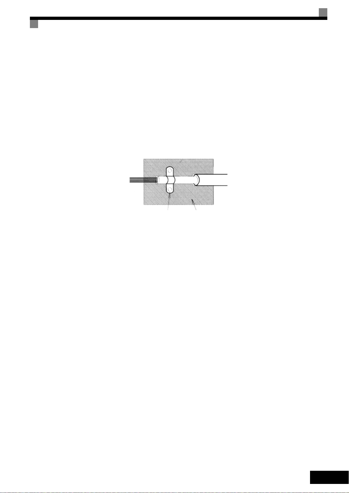
Verlegen von Kabeln
Maßnahmen gegen leitungsgebundene Störungen:
Netzfilter und Frequenzumrichter müssen auf dieselbe Metallplatte montiert werden. Montieren Sie die
beiden Bauteile so nah wie möglich nebeneinander, und halten Sie die Kabel so kurz wie möglich.
Verwenden Sie ein Netzkabel mit gut geerdeter Abschirmung. Verwenden Sie ein abgeschirmtes
Motorkabel. Ordnen Sie alle Erdungen so an, dass die Fläche des Kabelendes, die mit der
Erdungsklemme in Kontakt ist (z. B. Metallplatte), möglichst groß ist.
Abgeschirmtes Kabel:
• Verwenden Sie ein Kabel mit geflochtener Abschirmung.
• Erden Sie die größtmögliche Fläche der Abschirmung. Es ist ratsam, die Abschirmung durch
Verbinden des Kabels mit der Erdungsplatte durch Metallschellen (siehe nachfolgende
Abbildung) zu erden.
Erdungsschelle
Abb 1 Erdung der Kabelabschirmung mit Metallschellen
Die Erdungsflächen müssen aus hoch leitfähigem, blankem Metall bestehen. Entfernen Sie
Lack- und Farbbeschichtungen.
– Erden Sie die Kabelabschirmungen an beiden Enden.
– Erden Sie den Motor an der Maschine.
Erdungsplatte
DE-5
 Loading...