

Omron VARISPEED E7 DATASHEET
Manual No.
TOE-S616-56.1-03-OY
VARISPEED E7
Variable Torque Frequency Inverter
USER’S MANUAL

Table of Content
Warnings ............................................................................................... VII
Safety Precautions and Instructions for Use........................................ VIII
EMC Compatibility................................................................................. X
Line Filters ............................................................................................ XII
Registered Trademarks......................................................................... XV
1 Handling Inverters.................................................................. 1-1
Varispeed E7 Introduction ...........................................................................1-2
Varispeed E7 Applications .............................................................................................1-2
Varispeed E7 Models .....................................................................................................1-2
Confirmations upon Delivery .......................................................................1-4
Checks ...........................................................................................................................1-4
Nameplate Information ..................................................................................................1-4
Inverter Software Version ..............................................................................................1-5
Component Names ........................................................................................................1-6
Exterior and Mounting Dimensions ..............................................................1-9
IP00 Inverters ................................................................................................................1-9
NEMA 1 / IP20 Inverters ........................... ................................................ ...................1-10
IP54 Inverters ..............................................................................................................1-10
Checking and Controlling the Installation Site ...........................................1-13
Installation Site ....................................... .. ... ................................................................1-13
Controlling the Ambient Temperature .......................................................................... 1-13
Protecting the IP00 or NEMA 1 Inverter from Foreign Matter ......................................1-13
Additional Installation Precautions for the IP54 Inverters ............................................1-14
Keeping the IP54 protection ........................................................................................1-14
Installation Orientation and Space .............................................................1-15
Accessing the Inverter Terminals ..............................................................1-16
Removing the Terminal Cover (IP00 and NEMA 1 / IP20 Inverters) ...........................1-16
Attaching the Terminal Cover ......................................................................................1-16
Opening the Door (IP54 Inverters) ..............................................................................1-17
Closing the Door (IP54 Inverters) ...............................................................................1-17
Removing/Attaching the Digital Operator and Front Cover .......................1-18
Inverters of 18.5 kW or Less ........................................................................................1-18
Inverters of 22 kW or More ..........................................................................................1-20
2 Wiring....................................................................................... 2-1
Connection Diagrams ..................................................................................2-2
Circuit Descriptions ........................................................................................................2-4
Terminal Block Configuration ......................................................................2-5
Wiring Main Circuit Terminals ......................................................................2-7
Applicable Wire Sizes and Crimp Terminals ..................................................................2-7
Main Circuit Terminal Functions ..................................................................................2-15
Main Circuit Configurations ..........................................................................................2-16
Standard Connection Diagrams ...................................................................................2-18
Wiring the Main Circuits ...............................................................................................2-20
I

Wiring Control Circuit Terminals ...............................................................2-27
Wire Sizes ...................................................................................................................2-27
Control Circuit Terminal Functions ..............................................................................2-31
Control Circuit Terminal Connections ..........................................................................2-35
Control Circuit Wiring Precautions ..............................................................................2-36
Wiring Check .............................................................................................2-37
Checks ........................................................................................................................ 2-37
Installing and Wiring Option Cards ............................................................2-38
Option Card Models ........................................................ ............................................2-38
Installation in IP00 and NEMA 1 / IP20 Inverters ........................................................2-38
Installation in IP54 Inverters ......................... ...............................................................2-39
3 Digital Operator and Modes....................................................3-1
Digital Operator ...........................................................................................3-2
Digital Operator Display ................................................................................................3-2
Digital Operator Keys .............................................................................................. .. ....3-3
Modes .........................................................................................................3-5
Inverter Modes ..............................................................................................................3-5
Switching Modes ...........................................................................................................3-6
Drive Mode ....................................................................................................................3-8
Quick Programming Mode .............................................................................................3-9
Advanced Programming Mode .............................................. ... ...................................3-11
Verify Mode .................................................................................................................3-15
Autotuning Mode ............................................ ............................................. ................3-17
4 Trial Operation.........................................................................4-1
Trial Operation Procedure ...........................................................................4-2
Trial Operation ........................................................................................ ....4-3
Application Confirmation ...............................................................................................4-3
Setting the Power Supply Voltage Jumper
(400 V Class Inverters of 75 kW or Higher) ...................................................................4-3
Power ON ......................................................................................................................4-3
Checking the Display Status .........................................................................................4-4
Basic Settings ................................................................................................................4-5
Selecting the V/f pattern ................................................................................................4-7
Autotuning .....................................................................................................................4-7
Application Settings .......................................................................................................4-9
No-load Operation .........................................................................................................4-9
Loaded Operation .......................................................................................................... 4-9
Check and Recording User Parameters .................................................................... ..4-10
Adjustment Suggestions ...........................................................................4-11
5 User Parameters......................................................................5-1
User Parameter Descriptions ......................................................................5-2
Description of User Parameter Tables .......................................................................... 5-2
II
Digital Operation Display Functions and Levels ..........................................5-3
User Parameters Available in Quick Programmi ng Mode .............................................5-4

User Parameter Tables ...............................................................................5-6
Setup Settings: A ...........................................................................................................5-6
Application Parameters: b ..............................................................................................5-8
Tuning Parameters: C ............................................................................................. ... ..5-15
Reference Parameters: d .............................................................................................5-18
Motor Parameters: E .................................................................................................. ..5-20
Option Parameters: F ..................................................................................................5-22
Terminal Function Parameters: H ................................................................................5-23
Protection Function Parameters: L ..............................................................................5-29
Special Adjustments: n ................................................................................................5-35
Digital Operator Parameters: o ....................................................................................5-36
Motor Autotuning: T .....................................................................................................5-40
Monitor Parameters: U .................................................................................................5-41
Setting Values that Change with the V/f Pattern Selection (E1-03) .............................5-46
Factory Settings that Change with the Inverter Capacity (o2-04) ................................5-47
6 Parameter Settings by Function............................................ 6-1
Carrier Frequency Selection ........................................................................6-2
Setting the Carrier Frequency ........................................................................................6-2
Frequency Reference ..................................................................................6-5
Selecting the Frequency Reference Source ........................................................... ... ....6-5
Using Multi-Step Speed Operation ................................................................................6-7
Run Command ............................................................................................6-9
Selecting the Run Command Source ............................................................................6-9
Stopping Methods ......................................................................................6-11
Selecting the Stopping Method when a Stop Command is Input .................................6-11
Using the DC Injection Brake .......................................................................................6-13
Using an Emergency Stop .................................................................. .........................6-14
Acceleration and Deceleration Characteristics ..........................................6-15
Setting Acceleration and Deceleration Times ..............................................................6-15
Preventing the Motor from Stalling During Acceleration
(Stall Prevention During Acceleration Function) ..........................................................6-17
Stall Prevention During Deceleration Function ............................................................6-19
Adjusting Frequency References ..............................................................6-21
Adjusting Analog Frequency References ....................................................................6-21
Jump Frequency Function (Operation Avoiding Resonance) ...................................... 6-23
Speed Limit
(Frequency Reference Limit Function) ......................................................6-24
Limiting Maximum Output Frequency ..........................................................................6-24
Limiting Minimum Frequency .......................................................................................6-24
Frequency Detection .................................................................................6-25
Speed Agreement Function ................................................ .. .......................................6-25
Improved Operating Performance .............................................................6-27
Torque Compensation for Sufficient Torque at Start
and Low-speed Operation .................................................. .........................................6-27
Hunting Prevention Function .......................................................................................6-28
Machine Protection ....................................................................................6-29
Preventing Motor Stalling During Operation ................................................................6-29
Load Detection .............................................................................................................6-30
Motor Overload Protection ...........................................................................................6-33
III

Motor Overheat Protection Using PTC Thermistor Inputs ...........................................6-35
Limiting Motor Rotation Direction and Output Phase Rotation ....................................6-37
Automatic Restart ......................................................................................6-38
Restarting Automatically After Momentary Power Loss ..............................................6-38
Speed Search ............................................................. .. ............................................. ..6-39
Continuing Operation at Constant Speed When Frequency Reference Is Lost .......... 6-44
Restarting Operation After Transient Fault (Auto Restart Function) .............. ... ... .......6-45
Inverter Protection .....................................................................................6-47
Inverter Overheat Protection .......................................................................................6-47
Input Phase Loss Detection Level ...............................................................................6-48
Ground Fault Protection ..............................................................................................6-48
Cooling Fan Control ....................................................................................................6-49
Setting the Ambient Temperature .......... ... ..................................................................6-49
OL2 Characteristics at Low Speed ..............................................................................6-50
Soft CLA Selection ......................................................................................................6-51
Input Terminal Functions ...........................................................................6-52
Temporarily Switching Operation between Digital Operator
and Control Circuit Terminals ......................................................................................6-52
Blocking the Inverter Output (Baseblock Command) ..................................................6-53
Multifunction Analog Input A2 Disable/Enable ............................................................6-53
Drive Enable/Disable ...................................................................................................6-54
Bypass Drive Enable ........................ ............................................. ... ... ........................6-54
Stopping Acceleration and Deceleration
(Acceleration/Deceleration Ramp Hold) ...................................................................... 6-54
Raising and Lowering Frequency References Using
Digital Input Signals (UP/DOWN) ................................................................................6-55
Trim Control Function ..................................................................................................6-58
Analog Frequency Reference Sample/Hold ................................................................6-59
Switching Operation Source to Communication Option Card .....................................6-60
Switching Operation Source to MEMOBUS communication .......................................6-60
AUTO/HAND Mode Switching by Digital Input ............................................................6-61
Jog Frequency Operation without Forwar d and Reverse Commands (FJOG/RJOG) 6-62
Stopping the Inverter on External Faults (External Fault Function) .............................6-63
IV
Output Terminal Functions ........................................................................6-64
Monitor Parameters ...................................................................................6-67
Using the Analog Monitor Parameters ........................................................................6-67
Individual Functions ..................................................................................6-69
Using MEMOBUS Communications ............................................................................6-69
Using the Timer Function ............................................................................................ 6-86
Using PI Control ..........................................................................................................6-87
Energy-saving .............................................................................................................6-98
Setting Motor Parameters .......................................................... ... ... ...........................6-99
Setting the V/f Pattern ...............................................................................................6-100
Motor Preheat Function .............................................................................................6-106
Emergency Override Function ...................................................................................6-108
High Slip Braking .......................................................................................................6-109
Digital Operator Functions ......................................................................6-110
Setting Digital Operator Functions ............................................................................6-110
Copying Parameters ..................................................................................................6-113
Prohibiting Writing Parameters from the Digital Operator .........................................6-117
Setting a Password .......... .. .......................................................................................6-117
Displaying User-set Parameters Only ....................................................................... 6-118

7 Troubleshooting ..................................................................... 7-1
Protective and Diagnostic Functions ...........................................................7-2
Fault Detection ...............................................................................................................7-2
Alarm Detection .............................................................................................................7-8
Operator Programming Errors .....................................................................................7-11
Autotuning Faults ....................................................................... .................................7-13
Digital Operator Copy Function Faults .........................................................................7-13
Troubleshooting .........................................................................................7-15
If Parameters Cannot Be Set .......................................................................................7-15
If the Motor Does Not Operate .....................................................................................7-16
If the Direction of the Motor Rotation is Reversed .......................................................7-17
If the Motor Does Not Put Out Torque or If Acceleration is Slow .................................7-17
If the Motor Operates at Highe r Speed than the Frequency Reference ......................7-17
If Motor Deceleration is Slow .......................................................................................7-18
If the Motor Overheats .................................................................................................7-18
If peripheral devices like PLCs or other are influenced
by the starting or running inverter 7-.................................... ............................................19
If the Earth Leakage Breaker Oper ates when a RUN Command is Input ...................7-19
If There is Mechanical Oscillation ................................................................................7-19
If the Motor Rotates Even When Inverter Output is Stopped .......................................7-20
If OV (Overvoltage) or OC (Overcurrent) is Detected
When a Fan is Started, or a Fan Stalls ........................................................................7-20
If Output Frequency Does Not Rise to Frequency Reference .....................................7-20
8 Maintenance and Inspection.................................................. 8-1
Maintenance and Inspection ........................................................................8-2
Periodic Inspection ................................................. ... ............................................. ... ... .8-2
Periodic Maintenance of Parts ............................................ .. ... ......................................8-4
Cooling Fan Replacement Outline .................................................................................8-5
Removing and Mounting the Control Circuit Terminal Card ..........................................8-7
9 Specifications ......................................................................... 9-1
Standard Inverter Specifications ..................................................................9-2
Specifications by Model .......................................................................................... ... ....9-2
Common Specifications .................................................................................................9-5
10 Appendix ............................................................................... 10-1
Inverter Application Precautions ................................................................10-2
Selection ......................................................................................................................10-2
Installation ....................................................................................................................10-2
Settings ........................................................................................................................10-3
Handling .......................................................................................................................10-3
Motor Application Precautions ...................................................................10-4
Using the Inverter for an Existing Standard Motor .......................................................10-4
Using the Inverter for Special Motors ..........................................................................10-5
Power Transmission Mechanism (Speed Reducers, Belts and Chains) .....................10-5
User Parameters .......................................................................................10-6
V

VI

Warnings
Cables must not be connected or disconnected, nor signal tests carried out, while the power is
The Varispeed E7 DC bus capacitor remains charged even after the power has been switched off. To
avoid an electric shock hazard, disconnect the frequency inverter from the mains before carrying out
maintenance. Then wait for at least 5 minutes after all LEDs have gone out.
Do not perform a withstand voltage test on any part of the Varispeed. The frequency inverter contains semiconductors, which are not designed for such high voltages.
Do not remove the digital operator while the mains supply is switched on. The printed circuit board
must also not be touched while the inverter is connected to the power.
CAUTION
switched on.
Never connect general LC/RC interference suppression filters, capacitors or overvoltage protection devices to
the inverter input or output.
To avoid unnecessary overcurrent faults, etc. being displayed, the signaling contacts of any contactor or switch fitted between inverter and motor must be integrated into the inverter control logic
(e.g. baseblock).
This is absolutely imperative!
This manual must be read thoroughly before connecting and operating the inverter. All safety precautions and instructions for use must be followed.
The inverter may must be operated with the appropriate line filters, following the installation
instructions in this manual and with all covers closed and terminals covered.
Only then will adequate protection be provided. Please do not connect or operate any equipment
with visible damage or missing parts. The operating company is responsible for any injuries or
equipment damage resulting from failure to heed the warnings in this manual.
VII

Safety Precautions and Instructions for Use
General
Please read these safety precautions and instructions for use thoroughly before installing and operating this
inverter. Also read all of the warning signs on the inverter and ensure they are never damaged or removed.
Live and hot inverter components may be accessible during operation. Removal of housing components, the
digital operator or terminal covers runs the risk of serious injuries or damage in the event of incorrect installation or operation. The fact that frequency inverters control rotating mechanical machine components can give
rise to other dangers.
The instructions in this manual must be followed. Installation, operation and maintenance may only be carried
out by qualified personnel. For the purposes of the safety precautions, qualified personnel are defined as individuals who are familiar with the installation, starting, operation an d maintenance of frequency inv erters and
have the proper qualifications for this work. Safe operation of these units is only possible if they are used
properly for their intended purpose.
The DC bus capacitors can remain live for about 5 minutes after the inverter is disconnected from the power.
It is therefore necessary to wait for this time before opening its covers. All of the main circuit terminals m ay
still carry dangerous voltages.
Children and other unauthorized persons must not be allowed access to these inverters.
Keep these Safety Precautions and Instructions for Use readily accessible and supply them to all persons with
any form of access to the inverters.
Intended Use
Frequency inverters are intended for installation in electrical systems or machinery.
Their installation in machinery and systems must conform to the following product standards of the Low Volt-
age Directive:
EN 50178, 1997-10, Equipping of Power Systems with Electronic Devices
EN 60204-1, 1997-12Machine Safety and Equipping with Electrical Devices
Part 1: General Requirements (IEC 60204-1:1997)/
Please note: Includes Corrigendum of September 1998
EN 61010-1, A2, 1995Safety Requirements for Information Technology Equipment
(IEC 950, 1991 + A1, 1992 + A2, 1993 + A3, 1995 + A4, 1996, modified)
CE marking is carried out to EN 50178, using the line filters specified in this manual and following the appro-
priate installation instructions.
Transportation and storage
The instructions for transportation, storage and proper handling must be followed in accordance with the technical data.
Installation
VIII
Install and cool the inverters as specified in the documentation. The cooling air must flow in the specified
direction. The inverter may therefore only be operated in the specified position (e.g. upright). Maintain the
specified clearances. Protect the inverters against impermissible loads. Components must not be bent nor insulation clearances changed. To avoid damage being caused by static electricity, do not touch any electronic
components or contacts.

Electrical Connection
Carry out any work on live equipment in compliance with the national safety and accident prevention regulations. Carry out electrical installation in compliance with the relevant regulations. In particular, follow the
installation instructions ensuring electromagnetic compatibility (EMC), e.g. shielding, grounding, filter
arrangement and laying of cables. This also applies to equipment with the CE mark. It is the responsibility of
the manufacturer of the system or machine to ensure conformity with EMC limits.
Your sup plier or Omron Yaskawa Motion Control representative must be contacted when using leakage current circuit breaker in conjunction with frequency inverters.
In certain systems it may be necessary to use additional monitoring and safety devices in compliance with the
relevant safety and accident prevention regulations. The frequency inverter hardware must not be modified.
Notes
The Varispeed E7 frequency inverters are certified to CE, UL, and cUL except the IP54 version which is certified to CE only.
IX

EMC Compatibility
Introduction
This manual was compiled to help system manufacturers using OMRON YASKAWA Motion Control
(OYMC) frequency inverters design and install electrical switch gear. It also describes the measures necessary
to comply with the EMC Directive. The manual's installation and wiring instructions must therefore be followed.
Our products are tested by authorized bodies using the standards listed below.
Product standard: EN 61800-3:1996
EN 61800-3; A11:2000
Measures to Ensure Conformity of OYMC Frequency inverters to the EMC Directive
OYMC frequency inverters do not necessarily have to be installed in a switch cabinet.
It is not possible to give detailed instructions for all of the possible types of installation. This manual therefore
has to be limited to general guidelines.
All electrical equipment produces radio and line-borne interference at various frequencies. The cables pass
this on to the environment like an aerial.
Connecting an item of electrical equipment (e.g. drive) to a supply without a line filter can therefore allow HF
or LF interference to get into the mains.
The basic countermeasures are isolation of the wiring of control and power components, proper grounding and
shielding of cables.
A large contact area is necessary for low-impedance grounding of HF interference. The use of grounding
straps instead of cables is therefore definitely advisable.
Moreover, cable shields must be connected with purpose-made ground clips.
Laying Cables
Measures Against Line-Borne Interference:
Line filter and frequency inverter must be mounted on the same metal plate. Mount the two components as
close to each other as possible, with cables kept as short as possible.
Use a power cable with well-grounded shield. For motor cables up to 50 meters in length use shielded cables.
Arrange all grounds so as to maximize the area of the end of the lead in contact with the ground terminal (e.g .
metal plate).
Shielded Cable:
– Use a cable with braided shield.
– Ground the maximum possible area of the shield. It is advisable to ground the shield by connecting the cable
to the ground plate with metal clips (see following figure).
X
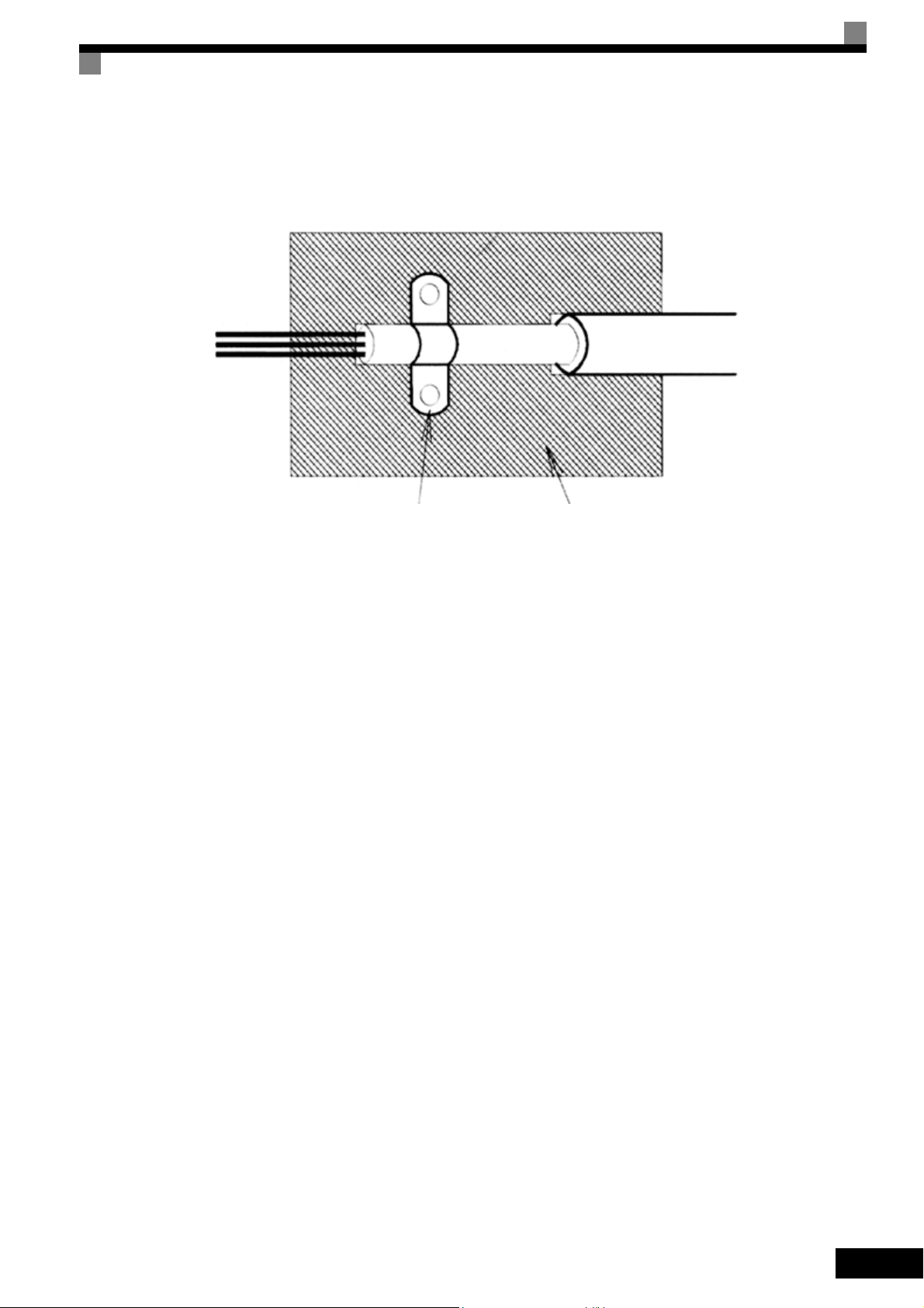
Ground clip Ground plate
The grounding surfaces must be highly conductive bare metal. Remove any coats of varnish and paint.
– Ground the cable shields at both ends.
– Ground the motor of the machine.
Further informations can be found in the document EZZ006543 which can be ordered at O mron Yaskawa
Motion Control.
XI

Line Filters
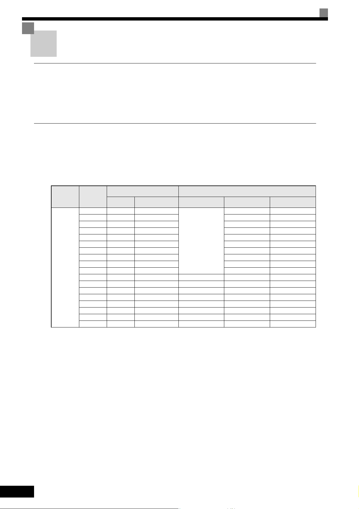
The IP54 version is already equipped with a internal EMC filter. For the IP00 and NEMA 1 / IP20 versions of
the Varispeed E7 the recommended line filters are as follows:
Recommended Line Filters for Varispeed E7 (IP00 and NEMA 1 / IP20)
Inverter Model Line Filter
Varispeed E7
(IP00/20)
CIMR-E7Z40P4
CIMR-E7Z40P7
CIMR-E7Z41P5
CIMR-E7Z42P2
CIMR-E7Z43P7
Model
3G3RV-PFI3010-SE
EN
55011 Class
Current
(A)
10 1.1 141 x 46 x 330
Weight
(kg)
Dimensions
W x D x H
3G3RV-PFI3018-SE 18 1.3 141 x 46 x 330CIMR-E7Z44P0
CIMR-E7Z45P5
CIMR-E7Z47P5
3G3RV-PFI3035-SE 35 2.1 206 x 50 x 355
CIMR-E7Z4011
CIMR-E7Z4015
3G3RV-PFI3060-SE 60 4.0 236 x 65 x 408
CIMR-E7Z4018
CIMR-E7Z4022
3G3RV-PFI3070-SE
CIMR-E7Z4030
CIMR-E7Z4037
3G3RV-PFI3130-SE 130 4.7 90 x 180 x 366CIMR-E7Z4045
CIMR-E7Z4055
CIMR-E7Z4075 3G3RV-PFI3170-SE 170 6.0 120 x 170 x 451
CIMR-E7Z4090
3G3RV-PFI3200-SE 250 11 130 x 240 x 610
CIMR-E7Z4110
CIMR-E7Z4132
3G3RV-PFI3400-SE 400 18.5 300 x 160 x 610
CIMR-E7Z4160
B, 25 m
A, 100 m
*1
70 3.4 80 x 185 x 329
XII
CIMR-E7Z4185
3G3RV-PFI3600-SE 600 11,0 260 x 135 x 386
CIMR-E7Z4220
CIMR-E7Z4300 3G3RV-PFI3800-SE 800 31.0 300 x 160 x 716
*1. Class A, 100 m
Permissible emission of power drive systems for commercial and light environm ent (EN61800-3, A11)
(general availability, 1st environment)

Inverter Model Line Filters
Varispeed E7
(IP00/20)
CIMR-E7Z20P4
Type
EN
55011
Class
Current
(A)
Weight
(kg)
Dimensions
W x D x H
3G3RV-PFI3010-SE
CIMR-E7Z21P5
CIMR-E7Z22P2 3G3RV-PFI3018-SE 18 1.3 141 x 46 x 330
CIMR-E7Z23P7
CIMR-E7Z25P5
3G3RV-PFI2035-SE 35 1.4 141 x 46 x 330
CIMR-E7Z27P5
3G3RV-PFI2060-SE 60 3 206 x 60 x 355
CIMR-E7Z2011
CIMR-E7Z2015
3G3RV-PFI2100-SE 100 4.9 236 x 80 x 408
CIMR-E7Z2018
CIMR-E7Z2022
3G3RV-PFI2130-SE
CIMR-E7Z2030
CIMR-E7Z2037 3G3RV-PFI2160-SE 160 6.0 120 x 170 x 451
CIMR-E7Z2045
3G3RV-PFI2200-SE 200 11.0 130 x 240 x 610
CIMR-E7Z2055
CIMR-E7Z2075
3G3RV-PFI3400-SE 400 18.5 300 x 160 x 564
CIMR-E7Z2090
B, 25 m
A, 100 m
*1
10 1.1 141 x 45 x 330CIMR-E7Z20P7
130 4.3 90 x 180 x 366
CIMR-E7Z2110 3G3RV-PFI3600-SE 600 11.0 260 x 135 x 386
*1. Class A, 100 ambient temperature: 45°C max
EMC Specifications of Varispeed E7 (IP54)
The Varispeed E7 IP54 is already equipped with an internal EMC filter. The Varispeed E7 IP54 complies with
EN55011 class A with a motor cable length up to 25m.
For the wiring methods to comply with the EMC regulations for the Varispeed E7 (IP54) refer to page Chap-
ter 2, Wiring.
XIII
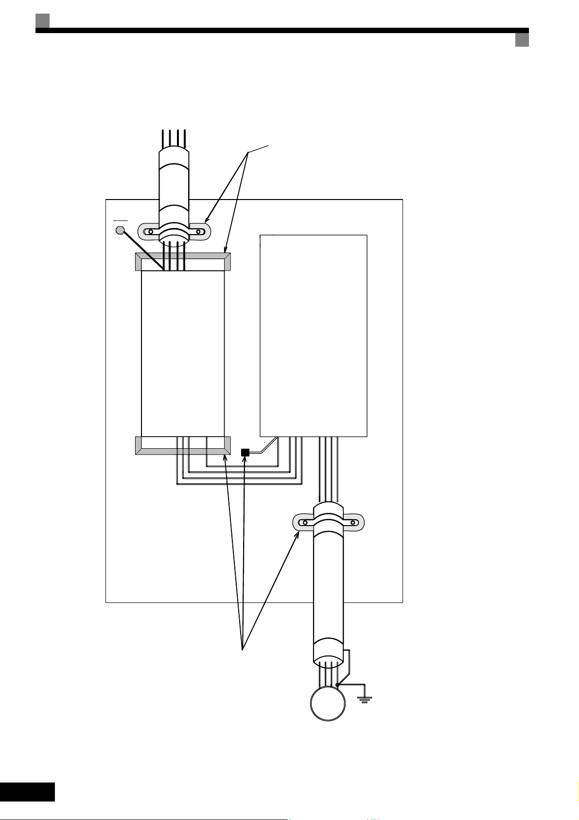
Installation inverters and EMC filters
L1 L3
L2
PE
PE
Line
Filter
Ground Bonds
( remove any paint )
Inverter
Load
Cable Length
as short as possible
Metal Plate
( remove any paint )
Ground Bonds
PE
L1L2L3
U
W
V
M
3~
PE
Motor cable
screened
XIV

Registered Trademarks
The following registered trademarks are used in this manual.
• DeviceNet is a registered trademark of the ODVA (Open DeviceNet Vendors Association, Inc.).
• InterBus is a registered trademark of Phoenix Contact Co.
• ControlNet is a registered trademark of ControlNet International, Ltd.
• LONworks is a registered trademark of the Echelon.
• Metasys is a registered trademark of Johnson Controls Inc.
• CANopen is a registered trademark of CAN in Automation e.V.
XV

XVI

Handling Inverters
This chapter describes the checks required upon receiving or installing an Inverter.
Varispeed E7 Introduction..................................................1-2
Confirmations upon Delivery..............................................1-4
Exterior and Mounting Dimensions....................................1-9
Checking and Controlling the Installation Site .................1-13
Installation Orientation and Space...................................1-15
Accessing the Inverter Terminals.....................................1-16
Removing/Attaching the Digital Operator and Front Cover1-18
1
Varispeed E7 Introduction
Varispeed E7 Applications
The Varispeed E7 is ideal for the following applications.
• Fan, blower and pump applications with variable torque characteristics.
Settings must be adjusted to the application for optimum operation. Refer to page 4-1, Trial Operation.
Varispeed E7 Models
The Varispeed E7 Series includes Inverters in two voltage classes: 200 V and 400 V. The maximum motor capacities
vary from 0.55 to 300 kW. The inverter is available in protection classes IP00, IP20 and IP54 according to the
following table:
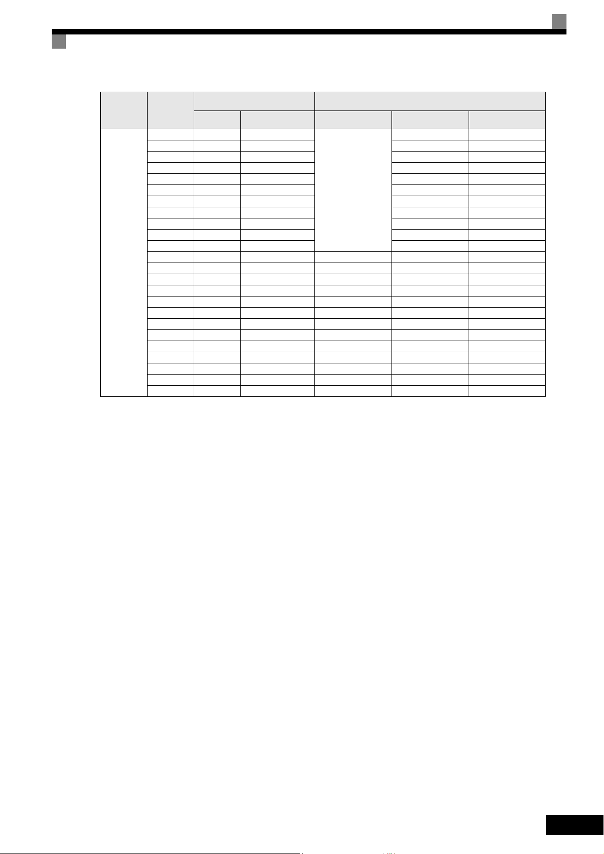
Table 1.1 Varispeed E7 Models
Specifications
NEMA 1 (IEC IP20)
CIMR-E7Z
20P41 -
CIMR-E7Z
Voltage Class
200 V class
Maximum
Motor
Capacity
kW
0.55 1.2 CIMR-E7Z20P4
0.75 1.6 CIMR-E7Z20P7 20P71 -
18.5 27 CIMR-E7Z2018 20181 -
110 160 CIMR-E7Z2110 21100 --
Capacity kVA
1.5 2.7 CIMR-E7Z21P5 21P51 -
2.2 3.7 CIMR-E7Z22P2 22P21 -
3.7 5.7 CIMR-E7Z23P7 23P71 -
5.5 8.8 CIMR-E7Z25P5 25P51 -
7.5 12 CIMR-E7Z27P5 27P51 -
11 17 CIMR-E7Z2011 20111 -
15 22 CIMR-E7Z2015 20151 -
22 32 CIMR-E7Z2022 20220 20221 -
30 44 CIMR-E7Z2030 20300 20301 -
37 55 CIMR-E7Z2037 20370 20371 -
45 69 CIMR-E7Z2045 20450 20451 -
55 82 CIMR-E7Z2055 20550 20551 -
75 110 CIMR-E7Z2075 20750 20751 -
90 130 CIMR-E7Z2090 20900 --
Output
Varispeed E7
Basic Model Number
(Always specify through the protective structure when ordering.)
IEC IP00
CIMR-E7Z
Remove the top and bot-
tom covers from the IP20
model.
IEC IP54
1-2
Varispeed E7 Introduction
Voltage Class
400 V class
Maximum
Motor
Capacity
kW
0.55 1.4 CIMR-E7Z40P4
0.75 1.6 CIMR-E7Z40P7 40P71 -
18.5 30 CIMR-E7Z4018 40181 40182
110 160 CIMR-E7Z4110 41100 41101 -
132 200 CIMR-E7Z4132 41320 41321 -
160 230 CIMR-E7Z4160 41600 41601 -
185 280 CIMR-E7Z4185 41850 -220 390 CIMR-E7Z4220 42200
300 510 CIMR-E7Z4300 43000 --
Capacity kVA
1.5 2.8 CIMR-E7Z41P5 41P51 -
2.2 4.0 CIMR-E7Z42P2 42P21 -
3.7 5.8 CIMR-E7Z43P7 43P71 -
4.0 6.6 CIMR-E7Z44P0 44P01 -
5.5 9.5 CIMR-E7Z45P5 45P51 -
7.5 13 CIMR-E7Z47P5 47P51 47P52
11 18 CIMR-E7Z4011 40111 40112
15 24 CIMR-E7Z4015 40151 40152
22 34 CIMR-E7Z4022 40220 40221 40222
30 46 CIMR-E7Z4030 40300 40301 40302
37 57 CIMR-E7Z4037 40370 40371 40372
45 69 CIMR-E7Z4045 40450 40451 40452
55 85 CIMR-E7Z4055 40550 40551 40552
75 110 CIMR-E7Z4075 40750 40751 -
90 140 CIMR-E7Z4090 40900 40901 -
Output
Varispeed E7
Basic Model Number
(Always specify through the protective structure when ordering.)
IEC IP00
CIMR-E7Z
Remove the top and bot-
tom covers from the IP20
model.
--
Specifications
NEMA 1 (IEC IP20)
CIMR-E7Z
40P41 -
IEC IP54
CIMR-E7Z
1-3
Confirmations upon Delivery
Checks
Check the following items as soon as the Inverter is delivered.
Table 1.2 Checks upon delivery
Item Method
Has the correct Inverter model been delivered? Check the model number on the nameplate on the side of the Inverter.
Is the Inverter damaged in any way?
Are any screws or other components loose? Use a screwdriver or other tools to check for tightness.
Additionally check that following parts are delivered in the package with the IP54 inverter:
Table 1.3 Additional Deliveries with IP54 Inverters
Cable Gland (for Input) 1
Cable Gland (for Motor Output) 1
Cable Gland (for Control) 1
Inspect the entire exterior of the Inverter to see if there are any
scratches or other damage resulting from shipping.
Part Name Qty.
Cable Gland (for Fieldbus) 1
Door Key 1
Blind Plug (Control Cable Entry) 1
Blind Plug (Fieldbus Cable Entry) 1
If any irregularities in the above items are found, contact the agency from which the Inverter was purchased or
your Omron Yaskawa Motion Control representative immediately.
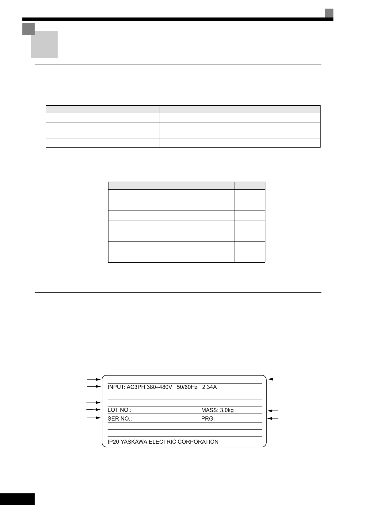
Nameplate Information
There is a nameplate attached to the side of each Inverter. The nameplate shows the model number, specifications, lot number, serial number, and other information on the Inverter.
Example Nameplate
The following nameplate is an example for a standard European Inverter: 3-phase, 400 VAC, 0.55 kW,
NEMA 1 / IP20 standards
Inverter model
Input specifications
Output specifications
Lot number
Serial number
MODEL: CIMR-E7Z40P4
OUTPUT: AC3PH 0-480V 0-200Hz 1.8A 1.4kVA
SPEC: 40P41A
Inverter
specifications
Mass
Software Number
1-4
Fig 1.1 Nameplate Example
Confirmations upon Delivery
T
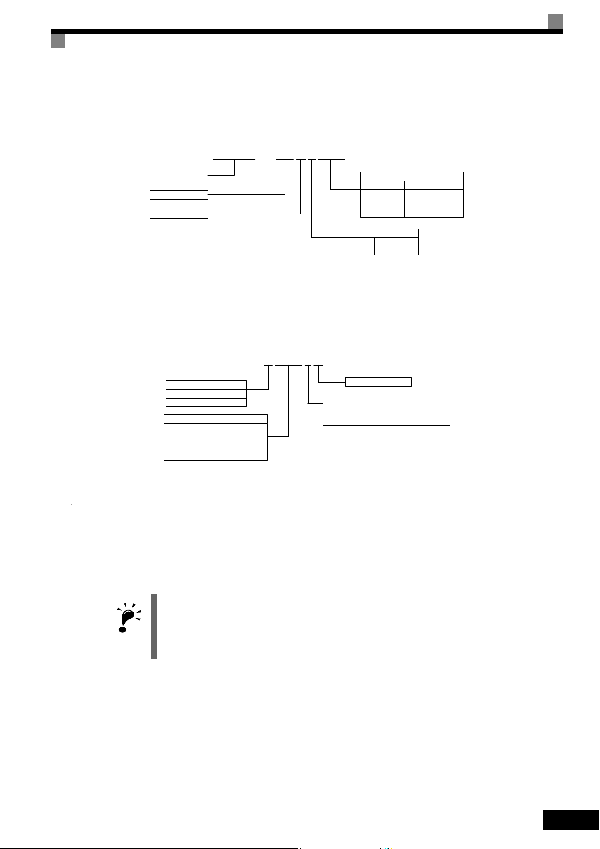
Inverter Model Numbers
The model number of the Inverter on the nameplate indicates the specification, voltage class, and maximum
motor capacity of the Inverter in alphanumeric codes.
CIMR – E7Z40P4
Inverter
Varispeed E7
European Spec.
Max. Motor Power
0P4 0.55 kW
0P7 0.75 kW
to to
300 300 kW
Voltage Class
2 200 V
4 400 V
Fig 1.2 Inverter Model Numbers
Inverter Specifications
The Inverter specifications (“SPEC”) on the nameplate indicate the voltage class, maximum motor capacity,
the protective structure, and the revision of the Inverter in alphanumeric codes.
40P41A
Voltage Class
2 200 V
4 400 V
Max. Motor Power
0P4 0.55 kW
0P7 0.75 kW
to to
300 300 kW
Revision
Protection
0 IP00
1 IP20
2 IP54
Fig 1.3 Inverter Specifications
Inverter Software Version
The Inverter software version can be read out from the monitor parameter U1-14. The parameter shows th e
last four digits of the software number (e.g. display is “3021” for the software version VSE103021).
This manual describes the functionality of the inverter software version VSE103021.
Older software versions do not support all described functions. Check the software versions before
IMPORTAN
starting to work with this manual.
1-5
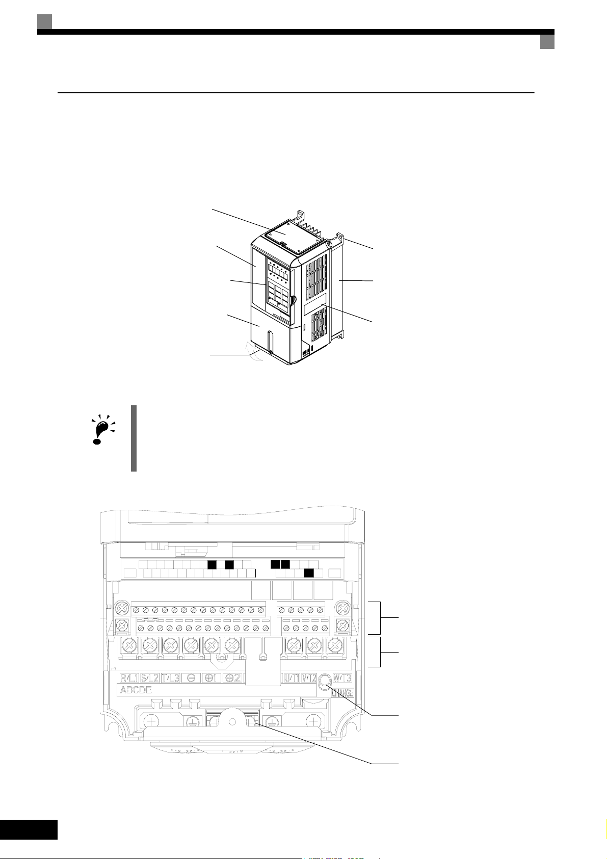
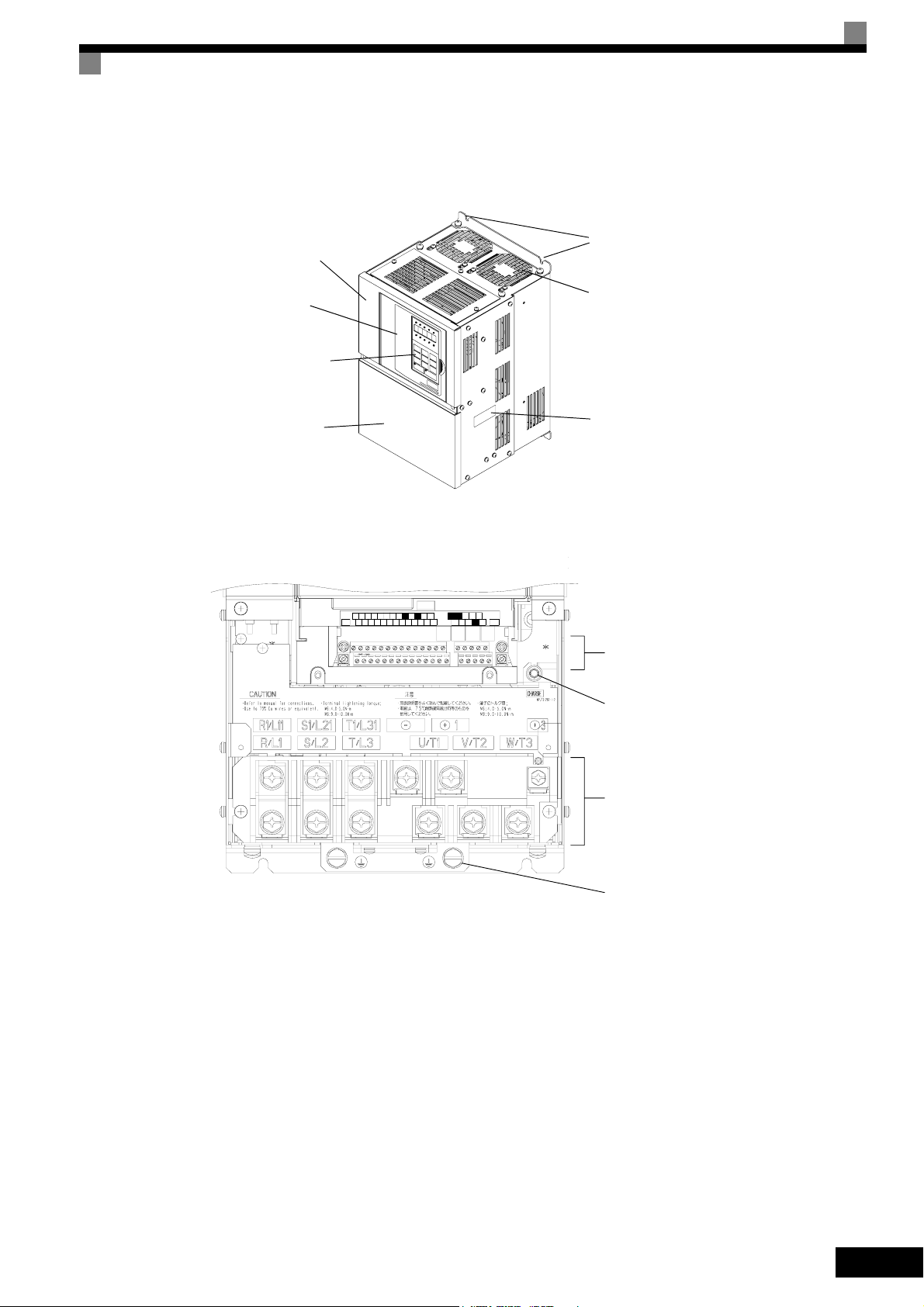
Component Names
Inverters of 18.5 kW or Less
The external appearance and component names of the Inverter are shown in Fig 1.4, the terminal arrangement
in Fig 1.5
Top cover
IMPORTANT
Front cover
Digital Operator
Mounting hole
Diecast case
Terminal cover
Nameplate
Bottom protective cover
Fig 1.4 NEMA 1 Inverter Appearance (18.5 kW or Less)
The top cover is a protection against foreign bodies (screws, metal scrap from drilling etc.), which could fall
into the inverter during the installation in the cabinet.
Remove the top cover when the installation is finished!
1-6
R+M5RPAC
MP
AC
-V
SCIGA2
SN M6
E(G)
S1 S4SPS7 M4
+V
A1
S3
FM
S6
S5 M1
R-
AC
AM
S+
S-
NOTUSED
Fig 1.5 Terminal Arrangement (18.5 kW or less)
MCMB
MA
M2
M3S2
E(G)
Control Circuit Terminals
Main Circuit Terminals
Charge Indicator
Ground Terminal
Confirmations upon Delivery
Inverters of 22 kW or More
The external appearance and component names of the Inverter are shown in Fig 1.6, the terminal arrangement
in Fig 1.7
Mounting holes
Inverter cover
Front cover
Digital Operator
Terminal cover
Cooling fan
Nameplate
Fig 1.6 Inverter Appearance (22 kW or More)
AC
R+M5RPAC
+VS3SCIGA2M2SN
A1
MP
R-
M6
MCMB
E(G)
S1 S4SPS7 M4
ACS6-VAM
FM
S5 M1
MA
S-
E(G)
M3S2 S+
Control Circuit Terminals
Carge Indicator
Fig 1.7 Terminal Arrangement (22kW or More)
Main Circuit Terminals
Ground Terminals
1-7
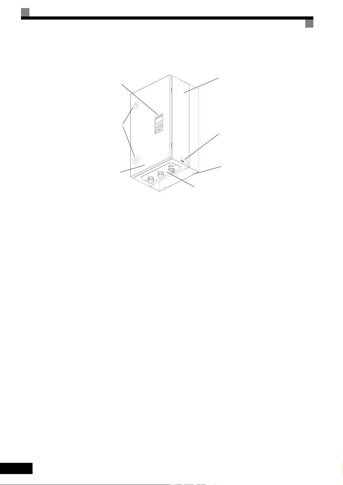
Protection Class IP54
The external appearance and component names of the Inverter are shown in Fig 1.8.
Inverter enclosure
Digital Operator
Door Locks
Nameplate
Mounting Holes
Door
Cable Entry Plate
Fig 1.8 IP54 Inverter Appearance
1-8
Exterior and Mounting Dimensions
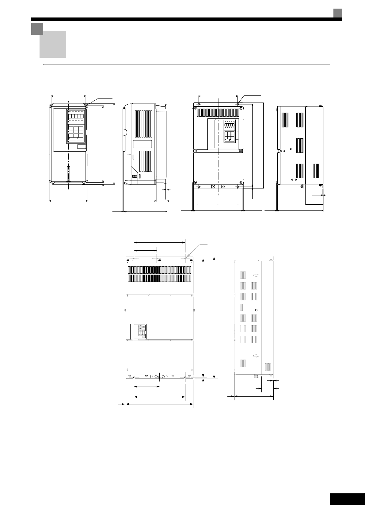
IP00 Inverters
Exterior and Mounting Dimensions
W1
W
200 V/400 V Class Inverters of 0.55 to 18.5 kW
4-d
H1H2DH
D1
3
W2
W1
W1
t1
Max.10
200 V Class Inverters of 22 or 110 kW
400 V Class Inverters of 22 to 160 kW
W
Ø
4-d
H1
H2
Max.10
H
t1
D1
5
D
W3
W1
15
400 V Class Inverters of 185 to 300 kW
W
Fig 1.9 Exterior Diagrams of IP00 Inverters
H
H1
t1
H2
5
D1
D
1-9
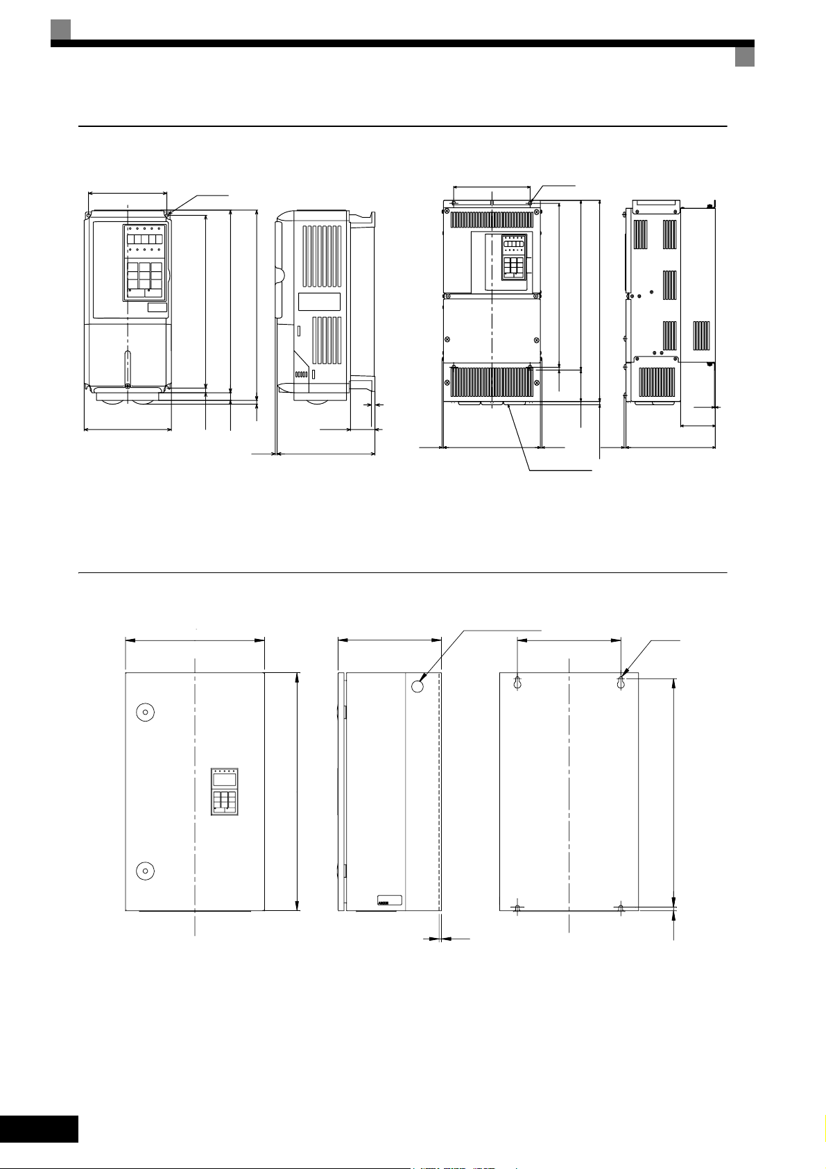
NEMA 1 / IP20 Inverters
W1
W
200 V/400 V Class Inverters of 0.55 to 18.5 kW
4-d
H1H2DH0
H3
4 H
3
Fig 1.10 Exterior Diagrams of NEMA 1 / IP20 Inverters
D1
W1
t1
Max.10
200 V Class Inverters of 22 to 75 kW
400 V Class Inverters of 22 to 160 kW
W
4-d
H1
H2
Max.10
Grommet
H0
H3
H
Max.10
t1
D1
D5
IP54 Inverters
WW1
D
H
2 - lifting holes
t1
Fig 1.11 Exterior Diagrams of IP54 Inverters
4-d
H1H2
1-10
Exterior and Mounting Dimensions
Table 1.4 Inverter Dimensions (mm) and Masses (kg) from 0.4 to 160 kW, IP00 and NEMA 1 / IP20
Max.
Voltage
Class
Appli-
cable
Motor
Output
W H D W1 H1 H2 D1 t1
[kW]
Protection Class IP00 Protection Class NEMA 1 / IP20
0.55
0.75 27 42 69
1.5 50 50 100
140 280
2.2 70 59 129
3.7
5.5 164 84 248
7.5
200 300 197 186 285 7.5 65.5
11 7 310 10 7 374 170 544
200 V
15
(3-
phase)
240 350 207 216 335 8 78 11 240
18.5 380 30 501 211 712
22 250 400
30 275 450 220 435 24 279 615 220 450 435 165 27 865 352 1217
37
375 600
45 328
55
450 725 348 325 700
75 87 95 2019 838 2857
90 500 850 358 370 820
110 575 885 378 445 855 140 150 --- 2733 1242 3975
157
39
126 266 7
177 59 4 177 59 4
2.3
195 385
258
298
250 575
7.5 100
12.5
100
3.2
130
15 4.5
0.55
0.75 17 41 58
157
39
1.5 36 48 84
140 280
2.2
3.7 80 68 148
4.0 91 70 161
126 266 7
177 59 4 177 59 4
5.5 127 82 209
7.5
200 300 197 186 285 8 65.5
11 252 158 410
15
400 V
(3-
phase)
240 350 207 216 335
18.5 426 208 634
22
279 450 258 220 435 100 21 279 535 258 220 450 435
30 678 317 995
78 10 240 350 207 216 350 335
2.3
7.5
37
325 550 283 260 535 105 36 329
45
55 1203 495 1698
75
450 725 348 325 700 12.5
90 89 97 1614 671 2285
110
500 850 358 370 820 15
132 120 130 2388 1002 3390
3.2
130
4.5
160 575 916 378 445 855 45.8 140 160 579 1324 378 445 916 855 46 408 140 170 2791 1147 3938
Dimensions (mm)
Appr
ox.
W H D W1 H0 H1 H2 H3 D1 t1
Mass
3
5
140 280
6
200
21 254 535
57
380 809
63 328
86
453 1027 348 325 725 700 302
157
126 280 266 7
300
197 186 300 285 8 65.5
350
207 216 350 335
195 400 385 135
258
298
250 600 575
7.5
12.5
0
0
209
39
78 11
100
100
130
108 504 1243 358 370 850 820 15 390 4.5 114
3
5
140 280
157
126 266 266 7
39
0
6 200 300 197 186 300 285 8 65.5
78 10
7.5
100 24
85
635
283 260 550 535 105 40
715 165
88
453 1027 348 325 725 700 12.5 302
102
504 1243 358 370 850 820 15 393
130
Appr
ox.
Mass
3
5
6
2.3
24 586 274 860
62
68 1266 505 1771
3.2
94 1588 619 2207
3
5
6
2.3
96
3.2
122
4.5
Moun
Exter
ting
nal
Holes
d*
20 39 59
M5
112 74 186
219 113 332
429 183 612
M6
1015 411 1426
M10
2437 997 3434
M12
14 39 53
M5
59 56 115
193 114 307
326 172 498
M6
466 259 725
784 360 1144
901 415 1316
1399 575 1974
M10
2097 853 2950
M12
Caloric Value
(W)
Total
Heat
Inter-
Gen-
nal
eration
Cool-
ing
Metho
d
Natu-
ral
Fan
Natu-
ral
Fan
Table 1.5 Inverter Dimensions (mm) and Masses (kg) of 400V Class Inverters of 185 kW to 300 kW, IP00
Dimensions (mm) Caloric Value (W)
Protection Class IP00
Approx.
Mass
260
Mount-
ing
Holes d
Exter-
Internal
nal
3237 1372 4609
M12
Total
Heat
Genera-
tion
Voltage
Class
400V
(3-phase)
Max.
Applica-
ble Motor
Output
[kW]
W H D W1 W2 W3 H1 H2 D1 t1
185
710 1305 413 540 240 270 1270 15 125.5 4.5
300 916 1475 413 730 365 365 1440 15 125.5 4.5 405 5838 2320 8158
Cooling
Method
Fan220 280 3740 1537 5277
1-11

Table 1.6 Inverter Dimensions (mm) and Masses (kg) of 400V class inverters 7.5 to 55 kW, IP54
Voltage
Class
400V
(3-phase)
Max.
Applica-
ble Motor
Output
[kW]
7.5
18.5 655
W H D W1 H1 H2 t1
11 423
350 600
15
22
410 650 300 270 620 12 2.5 43
30 989
37
580 750 330 410 714 11 2.5 71
45 1317
55 1701
Dimensions (mm)
Approx.
Mass
240
260 576 9 2.5
260 30
Mount-
ing
Holes d
25
∅ 10
M8
∅ 12
M10
∅ 14
M10
Total
Heat
Genera-
tion
302
531
754
1145
Cooling
Method
Fan
1-12

Checking and Controlling the Installation Site
Checking and Controlling the Installation Site
Install the Inverter in the installation site described below and maintain optimum conditions.
Installation Site
Install the Inverter under the following conditions in a pollution degree 2 environment.
Type Ambient Operating Temperature Humidity
Protection Class IP20 and IP54 -10 to + 40 °C 95% RH or less (no condensation)
Protection Class IP00 -10 to + 45 °C 95% RH or less (no condensation)
Protection covers are attached to the top and bottom of the NEMA 1 and IP00 Inverters. Be sure to remove the
top cover before operating a 200 or 400 V Class Inverter with an output of 18.5 kW or less inside a panel.
• Observe the following precautions when mounting the Inverter.
• Install the Inverter in a clean location which is free from oil mist and d ust. It can be installed in a totally
enclosed panel that is completely shielded from floating dust.
• When installing or operating the Inverter, always take special care so that metal powder, oil, water, or
other foreign matter does enter the Inverter.
• Do not install the Inverter on combustible material, such as wood.
• Install the Inverter in a location free from radioactive materials and combustible materials.
• Install the Inverter in a location free from harmful gasses and liquids.
• Install the Inverter in a location without excessive oscillation.
• Install the Inverter in a location free from chlorides.
• Install the Inverter in a location without in direct sunlight.
• The IP54 Inverters provide protection from non-conductive dust and splashing water from all directions.
Install the Inverter indoors in a heated and controlled environment to avoid condensation inside the
Inverter.
• Keep any water or dust outside of the IP54 Inverter when wiring.
Controlling the Ambient Temperature
To enhance the reliability of operation, the Inverter should be installed in an environment free from extreme
temperature increases. If the IP00 or NEMA 1 Inverter is installed in an enclosed environment, such as a box,
use a cooling fan or air conditioner to maintain the internal air temperature below 45°C.
When the IP54 Inverter is installed in a environment with low temperatures or when the Invert er remains
switched off for a long time, condensation may occur inside the Inverter. In that case additional heaters may
effectively prevent condensation inside the inverter.
Protecting the IP00 or NEMA 1 Inverter from Foreign Matter
Place a cover over the Inverter during installation to shield it from metal power produced by drilling.
Always remove the cover from the Inverter after completing installation. Otherwise, ventilation will be
reduced, causing the Inverter to overheat.
1-13
 Loading...