

Page 1

Cat. No.Z249-E1-04
RFID System
V680 Series
ID Controller
USER´S MANUAL
Page 2
RFID System
V680 Series
User's Manual
ID Controller
V680-CA5D01-V2
V680-CA5D02-V2
Cat. No. Z249-E1-04
Page 3

Introduction
Thank you for purchasing a V680-series RFID System. This manual describes the functions, performance,
and application methods needed for optimum use of the V680-series RFID System.
Please observe the following items when using the RFID System.
• Allow the RFID System to be installed and operated only by qualified specialist with a sufficient
knowledge of electrical systems.
• Read and understand this manual before attempting to use the RFID System and use the RFID System correctly.
• Keep this manual in a safe and accessible location so that it is available for reference when required.
Page 4

Introduction
Introduction
SECTION 1
SECTION 2
SECTION 3
SECTION 4
SECTION 5
READ AND UNDERSTAND THIS DOCUMENT
SECTION 1 SECTION 2 SECTION 3 SECTION 4 SECTION 5 SECTION 6 SECTION 7
Product Overview
Installation, Connections, and Wiring
Preparations for Communications
Functions
Communications
SECTION 6
SECTION 7
Troubleshooting
Appendices
RFID System
V680-CA5D01-V2 ID Controller
V680-CA5D02-V2 ID Controller
User’s Manual
Page 5

Introduction
Introduction
READ AND UNDERSTAND THIS DOCUMENT
Please read and understand this document before using the products. Please consult your OMRON representative if you have any questions or comments.
WARRANTY
OMRON’s exclusive warranty is that the products are free from defects in materials and workmanship for a period of one year (or other period if specified)
from date of sale by OMRON.
OMRON MAKES NO WARRANTY OR REPRESENTATION, EXPRESS OR IMPLIED, REGARDING NON-INFRINGEMENT, MERCHANTABILITY, OR FITNESS FOR PARTICULAR PURPOSE OF THE PRODUCTS. ANY BUYER OR USER ACKNOWLEDGES THAT THE BUYER OR USER ALONE HAS
DETERMINED THAT THE PRODUCTS WILL SUITABLY MEET THE REQUIREMENTS OF THEIR INTENDED USE. OMRON DISCLAIMS ALL OTHER
WARRANTIES, EXPRESS OR IMPLIED.
LIMITATIONS OF LIABILITY
OMRON SHALL NOT BE RESPONSIBLE FOR SPECIAL, INDIRECT, OR CONSEQUENTIAL DAMAGES, LOSS OF PROFITS OR COMMERCIAL LOSS IN
ANY WAY CONNECTED WITH THE PRODUCTS, WHETHER SUCH CLAIM IS BASED ON CONTRACT, WARRANTY, NEGLIGENCE, OR STRICT LIABILITY.
In no event shall responsibility of OMRON for any act exceed the individual price of the product on which liability is asserted.
IN NO EVENT SHALL OMRON BE RESPONSIBLE FOR WARRANTY, REPAIR, OR OTHER CLAIMS REGARDING THE PRODUCTS UNLESS OMRON’S
ANALYSIS CONFIRMS THAT THE PRODUCTS WERE PROPERLY HANDLED, STORED, INSTALLED, AND MAINTAINED AND NOT SUBJECT TO CONTAMINATION, ABUSE, MISUSE, OR INAPPROPRIATE MODIFICATION OR REPAIR.
SUITABILITY FOR USE
THE PRODUCTS CONTAINED IN THIS DOCUMENT ARE NOT SAFETY RATED. THEY ARE NOT DESIGNED OR RATED FOR ENSURING SAFETY OF
PERSONS, AND SHOULD NOT BE RELIED UPON AS A SAFETY COMPONENT OR PROTECTIVE DEVICE FOR SUCH PURPOSES. Please refer to separate catalogs for OMRON's safety rated products.
OMRON shall not be responsible for conformity with any standards, codes, or regulations that apply to the combination of products in the customer’s application or use of the product.
At the customer’s request, OMRON will provide applicable third party certification documents identifying ratings and limitations of use that apply to the products. This information by itself is not sufficient for a complete determination of the suitability of the products in combination with the end product, machine,
system, or other application or use.
The following are some examples of applications for which particular attention must be given. This is not intended to be an exhaustive list of all possible uses
of the products, nor is it intended to imply that the uses listed may be suitable for the products:
• Outdoor use, uses involving potential chemical contamination or electrical interference, or conditions or uses not described in this document.
• Nuclear energy control systems, combustion systems, railroad systems, aviation systems, medical equipment, amusement machines, vehicles, safety
equipment, and installations subject to separate industry or government regulations.
• Systems, machines, and equipment that could present a risk to life or proper ty.
Please know and observe all prohibitions of use applicable to the products.
NEVER USE THE PRODUCTS FOR AN APPLICATION INVOLVING SERIOUS RISK TO LIFE OR PROPERTY WITHOUT ENSURING THAT THE SYSTEM
AS A WHOLE HAS BEEN DESIGNED TO ADDRESS THE RISKS, AND THAT THE OMRON PRODUCT IS PROPERLY RATED AND INSTALLED FOR THE
INTENDED USE WITHIN THE OVERALL EQUIPMENT OR SYSTEM.
PERFORMANCE DATA
Performance data given in this document is provided as a guide for the user in determining suitability and does not constitute a warranty. It may represent the
result of OMRON’s test conditions, and the users must correlate it to actual application requirements. Actual performance is subject to the OMRON Warranty
and Limitations of Liability.
CHANGE IN SPECIFICATIONS
Product specifications and accessories may be changed at any time based on improvements and other reasons.
It is our practice to change model numbers when published ratings or features are changed, or when significant construction changes are made. However,
some specifications of the product may be changed without any notice. When in doubt, special model numbers may be assigned to fix or establish key specifications for your application on your request. Please consult with your OMRON representative at any time to confirm actual specifications of purchased products.
DIMENSIONS AND WEIGHTS
Dimensions and weights are nominal and are not to be used for manufacturing purposes, even when tolerances are shown.
ERRORS AND OMISSIONS
The information in this document has been carefully checked and is believed to be accurate; however, no responsibility is assumed for clerical, typographical,
or proofreading errors, or omissions.
PROGRAMMABLE PRODUCTS
OMRON shall not be responsible for the user’s programming of a programmable product, or any consequence thereof.
COPYRIGHT AND COPY PERMISSION
This document shall not be copied for sales or promotions without permission. This document is protected by copyright and is intended solely for use in conjunction with the product. Please notify us before copying or reproducing this document in any manner, for any other purpose. If copying or transmitting this
document to another, please copy or transmit it in its entirety.
RFID System
2
User's Manual
Page 6
Introduction
Safety Precautions
● Alert Symbols for Safe Use
The following symbols are used in this manual to indicate precautions that must be observed to ensure safe
use of the V680-CA5D01-V2 / -CA5D02-V2. The precautions provided here contain important safety information. Be sure to observe these precautions.
The following signal words are used in this manual.
Indicates a potentially hazardous situation which, if not avoided, will result in minor or
WARNING
● Meanings of Alert Symbols
Indicates general prohibitions for which there is no specific symbol.
moderate injury, or may result in serious injury or death. Additionally, there may be
significant property damage.
Introduction
● Warning
WARNING
This Product is not designed to be used either directly or indirectly in applications that detect
human presence for the purpose of maintaining safety. Do not use this Product as a sensing
device for protecting human lives.
Regulations and Standards
The V680-CA5D01-V2 / -CA5D02-V2 conform to the following overseas regulations and standards.
1.UL Standards
The V680-CA5D01-V2 and V680-CA5D02-V2 meet UL (Underwriter's Laboratories Inc.) conditions.
UL508
Connect to either circuit type (1) or (2) listed below.
(1) Limited Voltage/Current Circuit (Approved under UL508)
A circuit that uses the secondary windings of an isolation transformer as its power supply and fulfills the
following conditions:
• Maximum voltage: 30 Vrms (42.4 V peak)
and
• Maximum current: (a) 8 A (including short-circuits) or
(b) Current limited by a circuit protection device (e.g., fuse) with the ratings listed
in the following table.
No-load voltage (V peak) Maximum current rating (A)
0 to 20 5.0
Over 20 to 30 100
Peak voltage
RFID System
User's Manual
3
Page 7

Introduction
Introduction
(2) A class 2 circuit with a maximum voltage of 30 Vrms (42.4 V peak) that uses a class 2 power supply unit
conforming to UL1310 or a class 2 transformer that conforms to UL1585 as its power source.
2. EMC Standards
The V680-CA5D01-V2 and V680-CA5D02-V2 meet the requirements of the following EC Directives.
EMC Standard: EN 61000-6-2
EN 61000-6-4
Precautions for Safe Use
Be sure to observe the following precautions to ensure safe use of the Product.
1. Do not use the Product in environments with flammable, explosive, or corrosive gasses.
2. Do not attempt to disassemble, repair, or modify the Product.
3. Tighten the base mounting screws and terminal block screws securely.
4. Be sure to use crimp terminals of the specified size for wiring.
5. If any cable has a locking mechanism, make sure that it has been locked before using the cable.
6. Make sure the power supplied by the DC power supply unit is within the rated power supply voltage (24
VDC +10%/
7. Do not connect the power supply in reverse.
8. Do not allow water or wires to enter the Product through gaps in the case. Otherwise, fire or electric shock
may occur.
9. Turn OFF the power to the Controller before attaching or removing an Amplifier or Antenna.
10.If an error is detected in the Product, immediately stop operation and turn OFF the power supply.
Consult with an OMRON representative.
11.Dispose of the Product as industrial waste.
12.Observe all warnings and precautions given in the body of this manual.
−15%) before using the Product.
RFID System
4
User's Manual
Page 8

Introduction
Precautions for Correct Use
Always observe the following precautions to prevent operation failure, malfunctions, and adverse effects on
performance and equipment.
1. Installation Environment
Do not use the Product in the following locations.
• Locations exposed to corrosive gases, dust, metallic powder, or salts
• Locations not within the specified operating temperature range
• Locations subject to rapid changes in temperature or condensation
• Locations not within the specified operating humidity range
• Locations subject to direct vibration or shock outside the specified ranges
• Locations subject to spray of water, oil, or chemicals
Introduction
2. Installation
• This Product uses a frequency band of 13.56 MHz to communicate with ID Tags. Some transceivers,
motors, inverters, switching power supplies, etc., generate electrical noise that will affect these communications. If any of these devices are located in the vicinity of the Product, they may affect communications with ID Tags, and may possibly damage the ID Tags. Prior to using the Product in the
vicinity of any of these devices, perform a test to determine whether the Product can be used under
the resulting influence.
• Observe the following precautions to minimize the effects of normal noise.
Ground the ground terminal on the Product and all metal objects in the vicinity of the Product to
(1)
100 Ω or less.
(2) Do not use the Product near high-voltage or high-current lines.
• The Product is not waterproof. Do not use it in an environment where mist is present.
• Do not expose the Product to chemicals that adversely affect the Product materials.
• Use a tightening torque of 1.2 N·m max.
• If multiple Antennas are mounted near each other, communications performance may decrease due
to mutual interference. Refer to Installing Antennas in the V680 Series User's Manual for Amplifiers,
Antennas, and ID Tags (Cat. No. Z262, Z248)
interference.
and check to make sure there is no mutual
3. Storage
Do not store the Product in the following locations.
• Locations exposed to corrosive gases, dust, metallic powder, or salts
• Locations not within the specified operating temperature range
• Locations subject to rapid changes in temperature or condensation
• Locations not within the specified storage humidity range
• Locations subject to direct vibration or shock outside the specified ranges
• Locations subject to spray of water, oil, or chemicals
4. Cleaning
• Do not clean the Product with paint thinner, benzene, acetone, or kerosene. These chemicals will dissolve the resin materials and case coating.
RFID System
User's Manual
5
Page 9

Introduction
Introduction
5. Communications with the Host Device
Communicate with the host device only after confirming that the CIDRW Controller has started. Also,
Meanings of Symbols
unstable signals may occur at the host interface when the CIDRW Controller is started. When initializing operation, clear the reception buffer at the host device or take other suitable methods to clear
unwanted signals.
6. Startup Precaution
Never turn OFF the power supply while the CIDRW Controller is starting, including when power is
turned ON, when the mode is changed, or when the CIDRW Controller is being reset. Doing so may
damage the CIDRW Controller.
Meanings of Symbols
Indicates particularly important points related to a function, including precautions and application
advice
.
Indicates page numbers containing relevant information.
Indicates reference to helpful information and explanations for difficult terminology.
RFID System
6
User's Manual
Page 10

Introduction
Table of Contents
Introduction
Safety Precautions 3
Regulations and Standards 3
Precautions for Safe Use 4
Precautions for Correct Use 5
Meanings of Symbols 6
Table of Contents 7
SECTION 1 Product Overview 9
Introduction
Features 10
Part Names and Functions 13
System Configuration 19
Application Flowchart 25
SECTION 2 Installation, Connections, and Wiring 27
Installation 28
Connection and Wiring 30
SECTION 3 Preparations for Communications 57
Switch Settings 58
Trial Operation 76
SECTION 4 Functions 79
Trigger Input 80
Write Protection 81
Tag Service Life Check 91
Tag Memory Check 93
Tag Memory Error Correction 94
Write Command Memory 95
Noise Monitor Function 96
RFID System
User’s Manual
7
Page 11

Introduction
Introduction
SECTION 5 Communications 97
Tag Operation and Command Status 98
V600-V680 Command Correspondence 101
V680 Commands 103
V600 Commands 172
SECTION 6 Troubleshooting 237
Self-diagnostic Function 238
Error Lists 240
Errors and Countermeasures 244
Maintenance and Inspection 245
Troubleshooting 246
SECTION 7 Appendices 251
Specifications and Dimensions 252
Characteristics According to Operating Conditions 256
Tag Memory Map 265
Tag Memory Capacity and Memory Type 266
ASCII Table 267
Degree of Protection 268
Revision History 270
RFID System
8
User’s Manual
Page 12

SECTION 1 Product Overview
Features 10
Part Names and Functions 13
System Configuration 19
Application Flowchart 25
SECTION 1
Product Overview
RFID System
User’s Manual
9
Page 13
SECTION 1
Product Overview
Features
SECTION 1
Features
The V680-CA5D01-V2 / -CA5D02-V2 ID Controllers connect to V680-HA63 Amplifiers and V680-HS@@
Antennas, or to V680-H01 Antennas, to read and write data for V680-series ID Tags according to commands
from the host device. The ID Controller returns the results of executing these commands as responses to the
host device.
The ID Controller can communicate with Tags that conform to ISO 18000-3 (ISO 15693). The ID Controller may not be able to
communicate with Tags that are not V680-series Tags. Always confirm that communications are possible in advance.
10
RFID System
User’s Manual
Page 14
SECTION 1
Product Overview
Differences between the V680-CA5D@@ and V680-CA5D@@-V2
The following functions have been added to the V680-CA5D@@-V2 in addition to those found on the
V680-CA5D@@. These functions are upward-compatible with the V680-CA5D@@, so the V680CA5D@@ can be directly replaced by the V680-CA5D@@-V2.
SECTION 1
New Commands Added
The following commands have been added.
READ TAG MEMORY
ERROR CORRECTION
WRITE TAG MEMORY
ERROR CORRECTION
READ ID ID Reads the Tag's ID code.
UID ADDITION SET US Sets whether or not UID should be added to the read command (RD) response.
QR Reads the Tag's memory contents. Also uses a memory check code to inspect
data reliability.
QW Writes data to the memory of the Tag. Also writes the memory check code for the
data reliability inspection to the memory of the Tag.
Communications Designations Added
Multi-access, FIFO, and selective have been added to the communications designations.
Note: These designations cannot be used for communications with the V680-D1KP@@.
V680-H01 Antenna Connection Supported
The V680-H01 Antenna can be used by setting DIP SW4, pin 8.
The V680-H01 Antenna can be connected only to the V680-CA5D01-V2 ID Controller. It cannot be used with the V680CA5D02-V2 ID Controller.
Features
High-speed Data Transmission Supported
High-speed data transmission is possible by setting DIP SW4, pin 10.
The high-speed mode cannot be used with the V680-H01 Antenna.
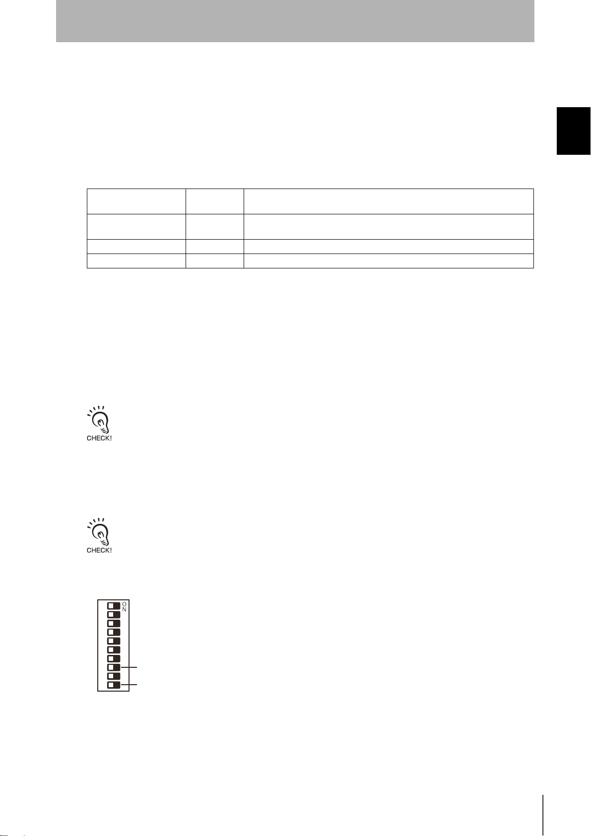
DIP SW4
1
2
3
4
5
6
7
8
9
0
V680-H01 Antenna connection setting (DIP SW4, pin 8)
High-speed Data Transmission setting (DIP SW4, pin 10)
Differences between Version 2.0 and Version 2.1 and Newer
The following functions have been added to version 2.1 and newer models in addition to those found
on version 2.0. These functions are upward-compatible with version 2.0, so version 2.0 can be directly
replaced with version 2.1.
RFID System
User’s Manual
11
Page 15

SECTION 1
Product Overview
Parameter Added to V600SP Command
SECTION 1
A write protect method has been added to the V600SP command.
Write Protect Method Added
The above-mentioned V600SP command can be set in the V600 command format to use the V600
Features
EEPROM write protection method or the V600 S-RAM write protection method.
12
RFID System
User’s Manual
Page 16

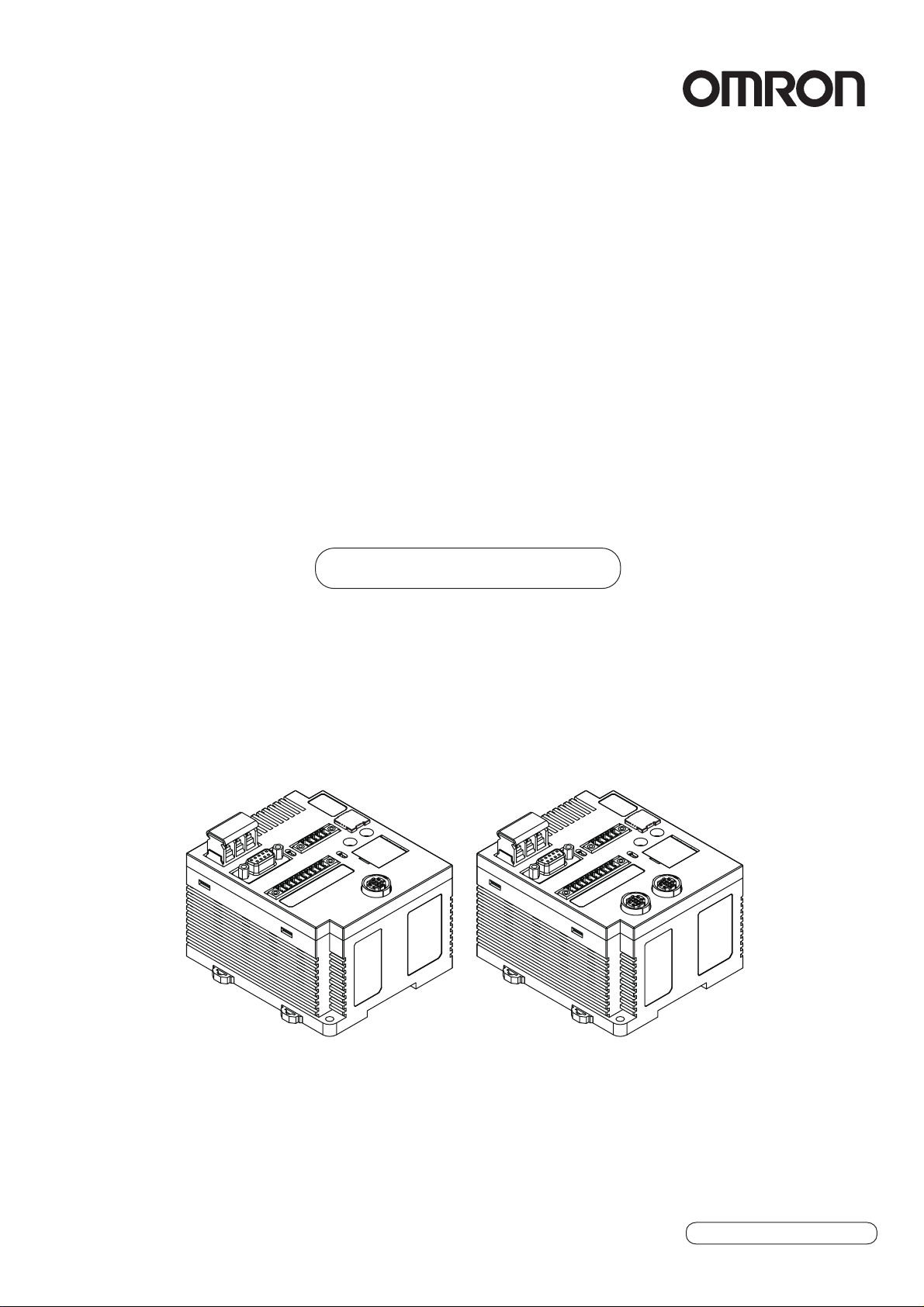
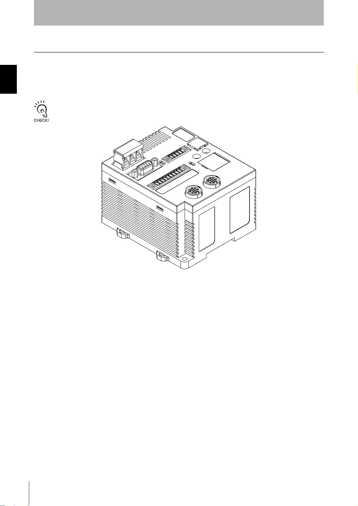
Part Names and Functions
SECTION 1
Product Overview
Part Names
V680-CA5D01-V2
RS-422/RS-485 Port
Terminating Resistance Switch
Power Supply Terminals
Ground Terminal
V680-CA5D02-V2
USB Port
Controller Number Switches
RS-232C Port
Main Indicators
Switch Cover
SECTION 1
Part Names and Functions
Monitor display
Bar Indicator
Mode Switch
Antenna Port
Antenna Operation Indicators
External I/O Port
USB Port
RS-422/RS-485 Port
Terminating Resistance Switch
Power Supply Terminals
Ground Terminal
Controller Number Switches
Switch Cover
RS-232C Port
Main Indicators
Monitor display
Bar Indicator
Mode Switch
Antenna Port
Antenna Operation
Indicators
External I/O Port
RFID System
User’s Manual
13
Page 17
SECTION 1
Part Names and Functions
SECTION 1
Product Overview
Power Supply and Ground Terminals
Description Description
Power supply terminals Supply 24 VDC power to these terminals.
Recommended power supply: OMRON S8VS-03024.
Ground terminal The ground terminal. Connect this terminal to an independent ground line connected to 100
less.
External I/O Port
The external I/O port is used to connect external I/O signals.
There are two external I/O signal arrangements that can be used for the same port: the same signal
arrangement as the V600-CA5D@@ and a signal arrangement unique to the V680-CA5D@@-V2.
The desired I/O signal arrangement can be specified using the PARAMETER SET (SP) command. In
Self-execution Mode, the use of ports other than RUN and RST can be set.
Ω. or
Description
V600 I/O V680 I/O
RUN Turns ON when the ID Controller is operating normally and the communications are possible with the
host device.
BUSY OUT3 BUSY: Output from when a tag communications command is received from the host device until tag
communications have been completed. This is the default setting.
OUT3: User output 3. This output can be controlled with the CONTROLLER CONTROL (CC) com-
mand.
ERROR OUT4 ERROR: Output for 500 ms when a tag communications error, host communications error, or hard-
ware error has occurred. The output time can be changed with the PARAMETER SET (SP)
command. This is the default setting.
OUT4: User output 4. This output can be controlled with the CONTROLLER CONTROL (CC) com-
mand.
OUT1 OUT1: User output 1. This output can be controlled with the CONTROLLER CONTROL (CC) com-
mand.
OUT2 OUT2: User output 2. This output can be controlled with the CONTROLLER CONTROL (CC) com-
mand.
COM_O Common terminal for outputs.
RST External reset input for emergency stops. The ID Controller is reset when an input is received.
TRG1 V680 Command System
If a trigger communications designation (SI, RI, or PI) is specified, the command received by Antenna
1 will be executed on the rising edge of the TRG1 input. If any other communications designation is
specified, TRG1 is used as user input 1, which can be read using the CONTROLLER CONTROL
(CC) command.
V600 Command System
If pin 6 on DIP switch SW4 (Lower Trigger Execution Setting) is turned ON, any command already
received by Antenna 1 will be executed on the rising edge of the TRG1 Input. If pin 6 is turned OFF,
TRG1 is used as user input 1, which can be read using the CONTROLLER CONTROL (CC) command.
TRG2 V680 Command System
If a trigger communications designation (SI, RI, or PI) is specified, the command received by Antenna
2 will be executed on the rising edge of the TRG2 input. If any other communications designation is
specified, TRG2 is used as user input 2, which can be read using the CONTROLLER CONTROL
(CC) command.
V600 Command System
If pin 6 on DIP switch SW4 (Lower Trigger Execution Setting) is turned ON, any command already
received by Antenna 2 will be executed on the rising edge of the TRG2 input. If pin 6 is turned OFF,
TRG2 is used as user input 2, which can be read using the CONTROLLER CONTROL (CC) command.
COM_I Common terminal for inputs
Description
14
RFID System
User’s Manual
Page 18

SECTION 1
Product Overview
RS-232C Port
The RS-232C port is used to communicate with a host device. A computer, PLC, or similar host device
with an RS-232C interface can be connected.
RS-422/RS-485 Port
The RS-422/RS-485 port is used to communicate with a host device. Computers, PLCs, and similar
host devices with RS-422/RS-485 interfaces can be connected.
USB Port
The USB port is used to connect to a computer via a USB cable. The port is USB 1.1.
Communications with host devices using USB connections can be made using only 1:1 protocol,
regardless of the setting of pin 9 on DIP switch SW3.
The USB port is not a control port. Always use the RS-232C port or RS-422/RS-485 port when building systems.
p. 19
SECTION 1
Part Names and Functions
Antenna Port
The antenna port is used to connect V680-series Amplifiers and Antennas.
Controller Number Switches
The Controller number switches are used to set the number of the ID Controller when connecting more
than one ID Controller to one host device.
Refer to Controller Number Switch Settings (SW1, SW2) for details on this switch.
p. 60
Switch Cover
There are two DIP switches behind the switch cover for making settings.
Refer to DIP Switch Settings (SW3, SW4) for details on these switches.
p. 61
Mode Switch
The mode switch is used to change the ID Controller's operation mode (between Run and
Maintenance Mode).
Refer to Mode Switch Setting for details on this switch.
p. 63
Terminating Resistance Switch
This switch can be use to connect or disconnect the internal terminating resistance.
Refer to Terminating Resistance for details on this switch.
p. 63
RFID System
User’s Manual
15
Page 19
SECTION 1
Part Names and Functions
SECTION 1
Product Overview
Main Indicators
Indicator Color Description
RUN/RST Green Lit while the ID Controller is operating normally.
Red Lit while external reset signal is being input.
COMM Green Lit during normal communications with a host device.
Red Lit when an error is detected for communications with a host device.
Antenna Operation Indicators
Indicator Color Description
COMM1 Yellow Lit during processing of commands for Tag communications by Antenna 1.
NORM1/
ERR1
COMM2
(See note.)
NORM2/
ERR2
(See note.)
Note: The V680-CA5D01-V2 does not have COMM2 or NORM2/ERR2 indicators.
Green Lights once upon normal completion of processing by Antenna 1.
Red Lights once when processing ends in an error at Antenna 1.
Ye l l o w
Green Lights once upon normal completion of processing by Antenna 2.
Lit during processing of commands for communications with Tags by Antenna 2.
Lights once when processing ends in an error at Antenna 2.
Red
Monitor Display
Indicator Color Mode Description
7-segment
display
(2 digits)
Red Run Mode Command Execution
Maintenance
Mode
Mode
Self-execution Mode
Distance Level Measurement Mode
Tag Communications
Test Mode
Speed Level Measurement Mode (read/write)
Noise Level Measurement Mode
Communications Success Rate Measurement
Mode
Displays end codes.
Converts and measures the Antenna output at six levels.
The level is displayed as either “EE” or 01 to 06.
“--” will be displayed if there is no Tag in the Antenna’s communications area.
Communicates with Tags and displays end codes.
p. 147
Repeatedly communicates with moving Tags and displays
the number of successful communications between 01 and
99. The display will show 99 even if more than 99 successful communications were made.
“EE” will be displayed if the first communication after the
Tag entered the communications area fails.
Displays the ambient noise level between 00 and 99.
Communicates 100 times with a Tag with no retries, and
displays the communications success rate between 01 and
99 (%). If no communications were successful, “EE” is displayed. If all communications were successful, “FF” is displayed.
16
RFID System
User’s Manual
Page 20
SECTION 1
Product Overview
Run Mode (SW5 OFF)
In Run Mode, the end codes for command processing is displayed. The end code is displayed in 2-digit
hexadecimal, as shown below.
The display is lit for normal and warning responses and flashes for error responses.
SECTION 1
Part Names and Functions
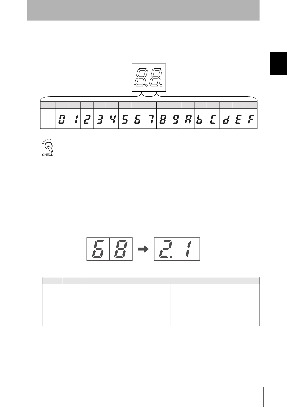
Hexadecimal
Display
0 1 2 3 4 5 6 7 8 9 A B C D E F
The error code “15” will be displayed if the operation conditions have not been set and operation is switched to
Self-execution Mode.
Maintenance Mode (SW5 ON)
In Maintenance Mode, the measurement results for each measurement mode is displayed in 2-digit
decimal.
Checking the Version
The version can be checked on the monitor display when turning ON the power.
Checking Method (example shows version 2.1)
1. Turn ON the power for the V680-CA5D0@-V2.
2. The following appears on the monitor display.
Bar Indicator
Indicator Color Description
1 Yellow The Antenna and the Tag are far apart. The Tag travel speed is fast.
2 Yellow
3 Yellow ||
4 Yellow ||
5 Yellow ↓↓
6 Yellow The Antenna and Tag are close. The Tag travel speed is slow.
↑↑
RFID System
User’s Manual
17
Page 21

SECTION 1
r
Part Names and Functions
SECTION 1
Product Overview
Bar Indicato
16
18
RFID System
User’s Manual
Page 22
System Configuration
SECTION 1
Product Overview
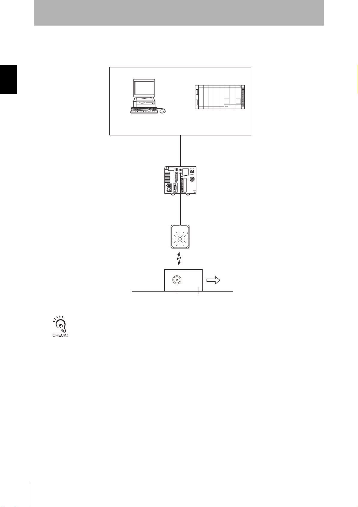
1:1 Connection
One host device is connected via the RS-232C, RS-422, or RS-485 interface.
• Using an Antenna Other than the V680-H01
Personal computer
Programmable Controller
(PLC)
RS-232C, RS-422, or
RS-485 interface
ID Controller
V680-CA5D01-V2
V680-CA5D02-V2
SECTION 1
System Configuration
Ta g
Amplifiers
V680-HA63 A/B
Antennas
V680-HS52
V680-HS63
V680-HS65
V680-HS51
Pallet or other object
RFID System
User’s Manual
19
Page 23
SECTION 1
Product Overview
• Using a V680-H01 Antenna
SECTION 1
System Configuration
Personal computer
Programmable Controller
(PLC)
RS-232C, RS-422, or
RS-485 interface
ID Controller
V680-CA5D01-V2
Antennas
V680-H01
Ta g
The V680-H01 Antenna can be connected only to the V680-CA5D01-V2 ID Controller. It cannot be used with the V680CA5D02-V2 ID Controller
Pallet or other object
20
RFID System
User’s Manual
Page 24

SECTION 1
Product Overview
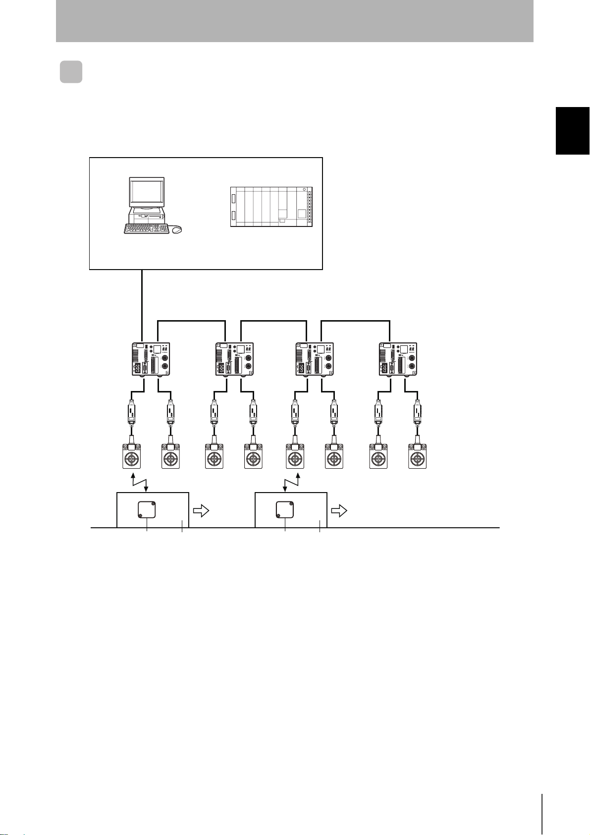
1:N Connections with RS-232C Connection to Host Device
The host device can be connected via RS-232C and then other ID Controllers can be connected via
RS-422/RS-485 interfaces.
• Using an Antenna Other than the V680-H01
SECTION 1
System Configuration
Personal computer
RS-232C
Programmable Controller
(PLC)
RS-422/RS-485 RS-422/RS-485 RS-422/RS-485
ID Controller
V680-CA5D01-V2
V680-CA5D02-V2
Amplifiers
V680-HA63 A/B
Antennas
V680-HS52
V680-HS63
V680-HS65
V680-HS51
Ta g
Pallet or other object
Ta g
Pallet or other object
RFID System
User’s Manual
21
Page 25

SECTION 1
Product Overview
• Using a V680-H01 Antenna
SECTION 1
System Configuration
Personal computer
RS-232C
Programmable Controller
(PLC)
RS-422/RS-485 RS-422/RS-485 RS-422/RS-485
ID Controller
V680-CA5D01-V2
Antennas
V680-H01
Ta g
Pallet or other object
Ta g
Pallet or other object
The V680-H01 Antenna can be connected only to the V680-CA5D01-V2 ID Controller. It cannot be used with the V680CA5D02-V2 ID Controller
22
RFID System
User’s Manual
Page 26
SECTION 1
Product Overview
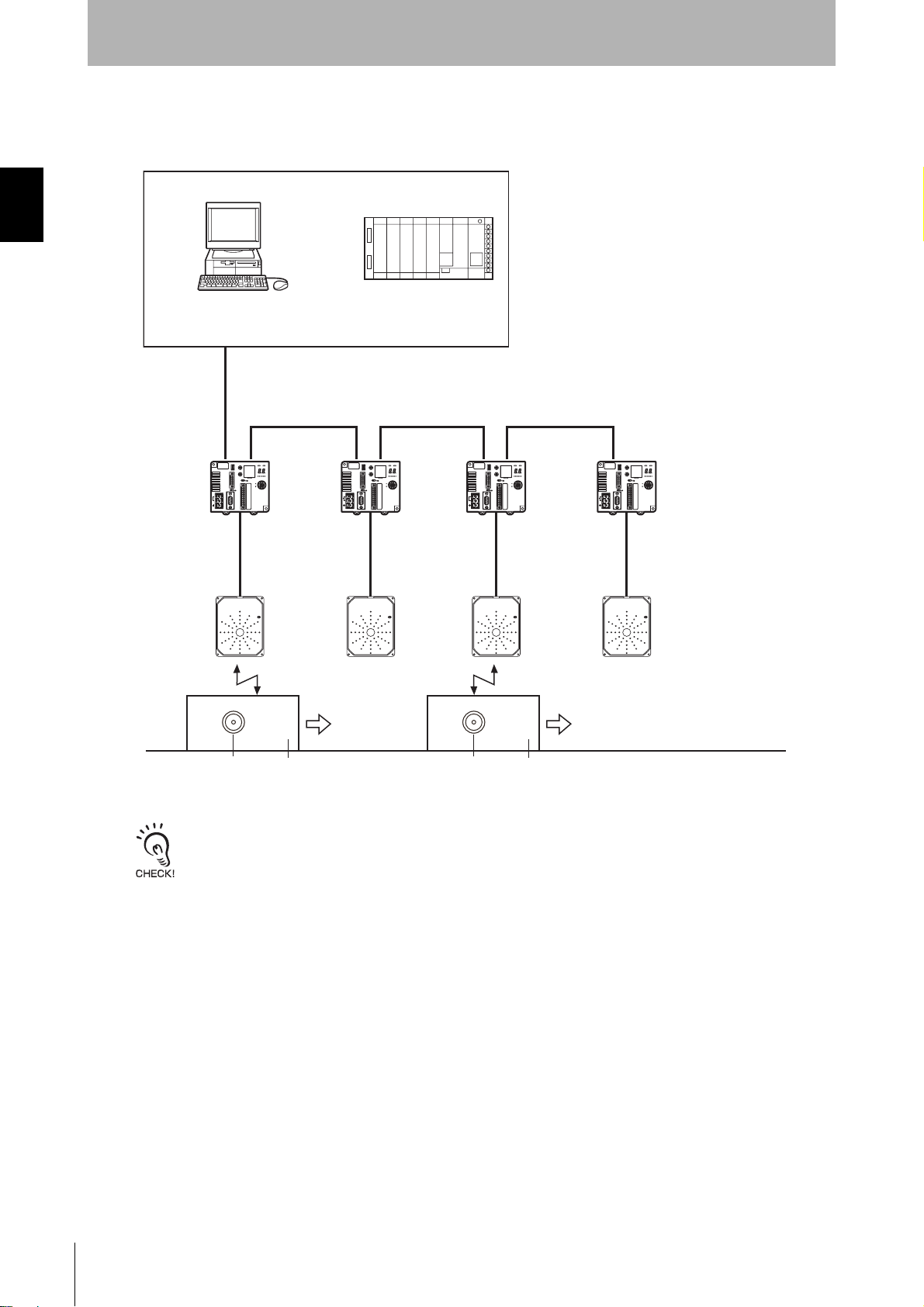
1:N Connections with RS-422/RS-485 Connection to Host
Device
The host device and other ID Controllers can all be connected via RS-422 or RS-485 interfaces.
• Using an Antenna Other than the V680-H01
Personal computer
RS-422/RS-485
RS-422/RS-485 RS-422/RS-485 RS-422/RS-485
Programmable Controller
(PLC)
ID Controller
V680-CA5D01-V2
V680-CA5D02-V2
SECTION 1
System Configuration
Ta g
Pallet or other object
Ta g
Amplifiers
V680-HA63 A/B
Antennas
V680-HS52
V680-HS63
V680-HS65
V680-HS51
Pallet or other object
RFID System
User’s Manual
23
Page 27
SECTION 1
Product Overview
• Using a V680-H01 Antenna
SECTION 1
System Configuration
Personal computer
RS-422/RS-485
Programmable Controller
(PLC)
RS-422/RS-485 RS-422/RS-485 RS-422/RS-485
ID Controller
V680-CA5D01-V2
Antennas
V680-H01
Ta g
Pallet or other object
Ta g
Pallet or other object
The V680-H01 Antenna can be connected only to the V680-CA5D01-V2 ID Controller. It cannot be used with the V680CA5D02-V2 ID Controller
24
RFID System
User’s Manual
Page 28
Application Flowchart
SECTION 1
Product Overview
SECTION 1
Preparation
Communications preparation
Install the system.
p. 28
Connect the system.
p. 30
Set the ID Controller's communications conditions.
p. 58
Perform a communications test between the ID Controller and host
device.
p. 77
Application Flowchart
Perform a communications test between the Tags and Antennas.
p. 78.
Trial operation
Check the ambient environment.
p. 245
Perform actual communications using commands.
p. 97
Communications
RFID System
User’s Manual
25
Page 29

SECTION 1
Application Flowchart
SECTION 1
Product Overview
MEMO
26
RFID System
User’s Manual
Page 30

SECTION 2 Installation, Connections, and Wiring
Installation 28
Connection and Wiring 30
SECTION 2
Installation, Connections, and Wiring
RFID System
User’s Manual
27
Page 31

SECTION 2
Installation, Connections, and Wiring
Installation
To increase the reliability of the V680-CA5D01-V2 / -CA5D02-V2 ID Controllers and ensure full functionality,
install the ID Controller according to the instructions provided in this section.
SECTION 2
Installation
Installation Site
Do not install the ID Controller in the following locations.
• Locations exposed to ambient temperatures that are not between −10 and 55°C or where there are
radical temperature changes resulting in condensation
• Locations exposed to humidity that is not between 25% and 85%
• Locations subject to corrosive gas, flammable gas, dust, salt, or metal powder
• Locations that will expose the ID Controller to direct vibration or shock
• Locations exposed to direct sunlight
• Locations exposed to spray of water, oil, or chemicals
• Locations more than 2,000 m above sea level
Mounting in a Panel
The ID Controller can be used at an ambient temperature range of −10 to 55°C. Be sure to observe the
following precautions.
• Make sure that the ID Controller is provided with sufficient ventilation space.
• Do not install the ID Controller close to heaters, transformers, or large-capacity resistors that radiate
excessive heat.
Installation Method
Mounting Directly in a Panel
Be sure to secure the ID Controller with two M4 screws together with spring washers and flat washers
when enclosing the ID Controller in a panel.
Recommended tightening torque: 1.2 N·m
80 90
95
10
Tw o, M 4
80
28
RFID System
User’s Manual
Page 32

Mounting to a DIN Track
DIN Track
SECTION 2
Installation, Connections, and Wiring
End Plate
1) First hook the Controller to part A, and then
press the Controller in direction B to mount the
Controller to the DIN Track.
2) To disconnect the Controller from the DIN Track,
Mounting hooks
End Plate
92
pull the mounting hook downwards, and then lift
A
OMRON PFP-100N2
(track length: 1 m)
is recommended.
B
Attaching the End Plates
To mount an End Plate easily, first hook the bottom of the End Plate and then hook the
top on the DIN Track, pull the End Plate downwards and tighten the screw.
Recommended tightening torque: 1.2 N·m.
the Controller upwards.
PFP-100N2
DIN Track
PFP-M
End Plate
SECTION 2
Installation
Mounting Interval
Leave a space of at least 10 mm between V680-CA5D01-V2/-CA5D02-V2 ID Controller. The ID Controllers will generate heat if they are mounted side-by-side.
10 mm min.
Spacer
Use at least 2 OMRON DIN Track Spacers. (Each Spacer is 5 mm wide.)
PFP-S
Spacer
10 mm min.
SpacerEnd Plate
End Plate
RFID System
User’s Manual
29
Page 33

SECTION 2
Connection and Wiring
SECTION 2
Installation, Connections, and Wiring
Connection and Wiring
Power Supply and Ground Wires
The power supply and ground terminals use M3 self-rising screws. The following type of crimp terminals can be connected to these terminals.
Recommended tightening torque: 0.5 N·m
Examples of Applicable Crimp Terminals
6.4 max.
6.4 max.
For M3 screw)
(
Manufacturer Model Applicable wire Ty pe
J.S.T. Mfg. Co., Ltd.
1.25-N3A
V1.25-N3A
1.25-MS3
V1.25-MS3
0.25 to 1.65 mm
AWG22 to AWG16
2
Forked
Round
• Provide 24 VDC to the Controller. The allowable fluctuation in the power supply is 24 VDC (
• ID Controllers have built-in noise countermeasures
against noise superimposed on the power supply line.
Ground noise can be reduced further by attaching a filter to the power supply line.
• Twisted-pair wire is recommended for the power line.
• To increase resistance to noise, ground to 100
less to an independent ground pole.
• Use a class 2 power supply.
Line filter
+ 24 V
−15%/+10%).
Ω or
Ferrite core
● Recommended Compact DC Power Supply (OMRON)
Model Output capacity Input voltage
S8VS-03024 24 VDC, 1.3 A 100 to 240 VAC
Note: The maximum power consumption of the Controller is
30 W (1.3 A at 24 VDC). The inrush current, however,
must be considered when selecting the power supply
capacity. A power supply with an output of 1.3 A min. at
24 VDC is recommended.
30
0 V
DC power supply
RFID System
User’s Manual
Ground to a resistance of 100
Ω or less
Page 34

SECTION 2
Installation, Connections, and Wiring
To reduce the influence of radiated noise, use a ferrite core.
Use the following procedure.
1. Wire the power supply and ground lines as normal.
2. Wrap the power supply lines and ground line together around the ferrite core. Loop them around the
ferrite core once so that the ferrite core does not move. The ferrite core should be within 10 cm of the
ID Controller.
SECTION 2
Connection and Wiring
3. Close the ferrite core until you hear it click into place.
Ferrite core
RFID System
User’s Manual
31
Page 35

SECTION 2
Connection and Wiring
SECTION 2
Installation, Connections, and Wiring
Wiring I/O Lines
Precautions for Reset Signal Input
• Be sure that the input voltage does not exceed the maximum applicable voltage (26.4 V).
The device may malfunction if the rated voltage is exceeded.
• To improve noise resistance, install the input line 1 m or more away from high-voltage devices and
power lines.
Reset input
24 VDC
24 VDC
To error output
Precautions for Error Signal Output
• The maximum switching capacity for the output is 100 mA at 24 VDC (−15% to +10%).
Do not use voltages or loads that exceed the switching capacity. Doing so may cause malfunctions.
• Use an auxiliary relay (24 VDC, 100 mA max.) to connect the output circuit.
Pin Arrangement
Pin No.
1RUN
2 BUSY OUT3
3 ERROR OUT4
4OUT1
5OUT2
6COM_O
7RST
8TRG1
9TRG2
10 COM_I
V600 I/O V680 I/O
Name
• Controller Terminal Arrangement
Terminal No.
12345678910
32
RFID System
User’s Manual
Refer to External I/O Port for details on the external I/O port.
p. 14
Page 36

Installation, Connections, and Wiring
Mounting Cables
Use the connectors provided with the ID Controller.
Manufacturer Model Remarks
Cable I/O lines --- --- 0.5 mm
Connector
Crimp terminals When connecting 1 line
to each terminal
When connecting 2
lines to each terminal
Crimping Tool CRIMPFOX UD6 ---
Phoenix Contact
MC1.5/10-STF-3.5 ---
AI0.5-8WH
AI-TWIN2
× 0.5-8WH
1. Attach the crimp terminals to the sections of the cable where the
sheath has been stripped.
2. Make sure the connector is facing the right direction and insert each
crimp terminal into the correct connector hole.
SECTION 2
2
(equivalent to AWG 20)
---
---
SECTION 2
Connection and Wiring
3. Firmly tighten the connector cable screws.
Recommended tightening torque: 0.22 N·m
Use a small flat-blade screwdriver with a uniform thickness. Do not
use a standard screwdriver with a tapered end. A standard screwdriver will not fully insert into the hole.
4. Once all of the cables have been connected to the connector,
attach the connector to the ID Controller.
Align the cable connector with the connector on the ID Controller. Hold the connector
body and push the connector firmly into place, and then tighten the connector lock
screws.
Recommended tightening torque: 0.4 N·m
Connector: MC1.5/10-STF-3.5
(manufactured by Phoenix Contact)
Small flat-blade screwdriver
with a tip of uniform thickness.
Lock screws
Removing the Connector
Completely loosen the two lock screws, hold the protruding part of the connector, and pull straight out. If
the connector is difficult to remove, press on the ID Controller while pulling on the connector.
Do not connect cables to the connector after attaching the connector to the ID Controller.
RFID System
User’s Manual
33
Page 37

SECTION 2
Installation, Connections, and Wiring
RS-232C Port
Pin Arrangement
SECTION 2
Connection and Wiring
Pin No. Symbol
9 SG --- --- Signal ground or common return line
2 SD --- Send data
3 RD --- Receive data
4 RS --- Request to send
5 CS --- Clear to send
Signal direction
Input Output
Signal name
The pin arrangement is different from that of the V680-CA1A. Use an RS-232C cable for the V680-CA5D@@-
V2.
Connections to Host Device
Example Connection to OMRON PLC
Host device
GR
SG
RD
SD
RS
CS
(Shield)
ID Controller
GR
SG
SD
RD
RS
CS
Recommended Cable
XW2Z-@@@TOMRON
• Controller Terminal Arrangement
51
96
Model Manufacturer
Note 1. Ground the shield at the host device side to prevent operation errors.
2. Short-circuit pins 4 (RS) and 5 (CS) inside the connector.
Example Connection to IBM PC/AT or Compatible Computer via D-SUB 9-pin Con-
nector
IBM PC/AT or compatible
GR
SG
RD
SD
RS
CS
Note 1. The interface cable will have a male connector on the ID Controller and a female connector on the IBM PC/AT or com-
patible.
2. Ground the shield at the host device to prevent operation errors.
Refer to Connections between ID Controllers (1:N) for information on 1:N connections.
p. 39
(
Shield)
ID Controller
GR
SG
SD
RD
RS
CS
Recommended Cable
Model Manufacturer
XW2Z-@@@S-V OMRON
34
RFID System
User’s Manual
Page 38

SECTION 2
Installation, Connections, and Wiring
Connecting to Ethernet
The ID Controller can be connected to the host device through an OMRON ITNC-SGB01 Serial Gate
Box to enable Ethernet TCP/IP communications. An ID Controller connected through a Serial Gate Box
can be communicated with in exactly the same way as when the ID Controller is connected through the
serial interface.
ID ControllerSerial Gate Box
GR
SG
RD
SD
RS
CS
(Shield)
Refer to the ITNC-SGB01 Serial Gate Box manual for details on the Serial Gate Box.
GR
SG
SD
RD
RS
CS
Model
ITNC-SGB01
Rated power supply volt-
age
DC24V +10%
−15%
Power consump-
tion
3 W max.
SECTION 2
Connection and Wiring
1:1 Connection
Personal computer
ID Controller
1:N Connections
Personal computer
10Base-T/100Base-TX
Serial Gate Box
ITNC-SGB01
RS-232C
RS-232C
ID Controller
10Base-T/100Base-TX
Serial Gate Box
ITNC-SGB01
RS-422/RS-485 RS-422/RS-485 RS-422/RS-485
ID ControllerID Controller ID Controller
RFID System
User’s Manual
35
Page 39

SECTION 2
Connection and Wiring
SECTION 2
Installation, Connections, and Wiring
Assembling and Connecting the Communications Connector
Have a connection cable and connector ready.
Controller end
OMRON
XM3B-0922-111
Plug
OMRON
XM2A-0901
Plug
OMRON
XM2S-0911
Hood
Assembling the Connector
1. Prepare the end of the cable as shown below.
5
Conductors
Braided shield
Shield tape
40
10±1
35
• Insert the cable into the cable bushing.
• Unravel the braided shield for approximately 10 mm and fold it
back on the cable bushing.
• Apply shield tape to the folded braided shield.
Cable bushing
12
Host device end
2. Solder the conductors to the plug pins.
Pin No. Symbol Signal name
9 SG Signal ground
2 SD Send data
3 RD Receive data
Plug Jumper
Aluminum
tape
Cable bushing
4 (See note.) RS Request to send
5 (See note.) CS Clear to send
Note: Short-circuit pins 4 (RS) and 5 (CS) with a jumper.
3. Attach housing A2 of the Hood to the Plug and secure the aluminum-taped portion with the cable
clamp.
Two, M2.6 lock screws
36
Housing A2
Cable clamp
Housing B2
4. Secure the two connector lock screws and put on housing B2 to complete the connector.
RFID System
User’s Manual
Page 40

SECTION 2
Installation, Connections, and Wiring
Connecting and Disconnecting the Connector
• When connecting the connector, be sure to hold the connector by hand and fully insert the connector.
Secure the connector by tightening the two lock screws with a Phillips screwdriver.
Recommended tightening torque: 0.3 N·m
• When disconnecting the connector, completely loosen the two lock screws. Hold the protruding part
of the connector hood by hand and pull the connector straight out. If the connector is difficult to disconnect, hold the ID Controller with your hand while pulling on the connector.
Lock screws
SECTION 2
Connection and Wiring
RFID System
User’s Manual
37
Page 41

SECTION 2
Connection and Wiring
SECTION 2
Installation, Connections, and Wiring
RS-422/RS-485 Port
Pin Arrangement
Pin No. Name Details
1RDA(
2 RDB(+) Receive data
3SDA(
4 SDB(+) Send data
5SGSG
Note: The port can be used as an RS-485 port if terminals 1 and
3, and 2 and 4 are short-circuited.
Connections to Host Device
RS-422 Connections
Shield)
Host device
SDA(
−)
SDB(
+)
−)
RDA(
RDB(
SG
GR
+)
(
−) Receive data
−) Send data
ID Controller
RDA(−)
+)
RDB(
SDA(
−)
SDB(
+)
SG
• Controller Terminal Arrangement
Terminal No.
12345
Note: Ground the shield at the host device to prevent operation errors.
RS-485 Connections
Host device
−
+
Note: Short-circuit terminals 1 and 3, and 2 and 4. Do not connect anything to the ID Controller signal ground.
RDA(−) RDB(+)SDA(−) SDB(+)SG
Reception
terminating
resistance
ID Controller
RDA(
RDB(
SDA(−)
SDB(
SG
Transmission
terminating
resistance
−)
+)
+)
Terminating resistance: 220 (Ω) for RS-422, 110 (Ω) for RS-485
Note: Turn ON terminating resistance only at the ID Controllers at the both ends
of the trunk cable. Turn OFF the terminating resistance at all ID Controllers
in between. Normal transmissions will not be possible if terminating
resistance is turned ON for the ID Controllers in between.
38
RFID System
User’s Manual
Page 42

Connections between ID Controllers (1:N)
RS-232C Connection to the Host Device
SW 6: ON
(terminating
resistance)
SW 6: OFF
(no terminating
resistance)
SECTION 2
Installation, Connections, and Wiring
SW 6: OFF
(no terminating
resistance)
SW 6: ON
(terminating
resistance)
Host device
Host device
RS-232C
RS-422
ID Controller
RS-422
ID ControllerID Controller
Max. length: 15 m Total length: 500 m max.
RS-232C
Pin No. Symbol
1RDA(−)
2 RDB(+)
3SDA(−)
4 SDB(+)
5SG
SW 6: ON
(terminating
resistance)
ID Controller
Pin No. Symbol
1RDA(−)
2 RDB(+)
3SDA(−)
4 SDB(+)
5SG
SW 6: OFF
(no terminating
resistance)
ID Controller
Pin No. Symbol
1RDA(−)
2 RDB(+)
3SDA(−)
4 SDB(+)
5SG
SW 6: OFF
(no terminating
resistance)
RS-485 RS-485RS-485
ID Controller
RS-422
ID Controller
Pin No. Symbol
1RDA(−)
2 RDB(+)
3SDA(−)
4 SDB(+)
5SG
SW 6: ON
(terminating
resistance)
ID Controller
SECTION 2
Connection and Wiring
Max. length: 15 m
Pin No. Symbol
1RDA(−)
2 RDB(+)
3SDA(−)
4 SDB(+)
5SG
Total length: 500 m max.
Pin No. Symbol Pin No. Symbol
1RDA(−)
2 RDB(+)
3SDA(−)
4 SDB(+)
5SG
1RDA(−)
2 RDB(+)
3SDA(−)
4 SDB(+)
5SG
Note: Short-circuit terminals 1 and 3, and 2 and 4 to use RS-485 communication.
Refer to Connections to Host Device for information on RS-232C connections between the host device and ID Controllers.
p. 34
If the first communications received by an ID Controller are via the RS-232C interface, reception of RS-422/RS-485
communications will be prohibited. If the first communications are received via RS-422/RS-485, reception of RS-232C
communications will be prohibited. Therefore, when changing the system configuration of an ID Controller, always turn
OFF the power supply before changing the connections.
Symbol
Pin No.
1RDA(−)
2 RDB(+)
3SDA(−)
4 SDB(+)
5SG
RFID System
User’s Manual
39
Page 43

SECTION 2
Installation, Connections, and Wiring
RS-422 Connection to Host Device
SW 6: OFF
(no terminating
resistance)
SW 6: OFF
(no terminating
resistance)
SW 6: OFF
(no terminating
resistance)
SW 6: ON
(terminating
resistance)
SECTION 2
Connection and Wiring
Host device
(terminating
resistance
connected)
RS-422
ID Controller
ID Controller
RS-422 RS-422RS-422
ID Controller
ID Controller
Total length: 500 m max.
Symbol
Pin No.
1 RDA(−)
2 RDB(+)
3 SDA(−)
4 SDB(+)
5SG
Symbol
Pin No.
1 RDA(−)
2 RDB(+)
3 SDA(−)
4 SDB(+)
5SG
Refer to RS-422 Connections for information on RS-422 connections between the host device and ID Controllers.
p. 38
If the first communications received by an ID Controller are via the RS-232C interface, reception of RS-422/RS-485
communications will be prohibited. If the first communications are received via RS-422/RS-485, reception of RS-232C
communications will be prohibited. Therefore, when changing the system configuration of an ID Controller, always turn
OFF the power supply before changing the connections.
Symbol
Pin No.
1 RDA(−)
2 RDB(+)
3 SDA(−)
4 SDB(+)
5SG
Symbol
Pin No.
1 RDA(−)
2 RDB(+)
3 SDA(−)
4 SDB(+)
5SG
RS-485 Connection to the Host Device
SW 6: OFF
(no terminating
resistance)
RS-485
Host device
(terminating
resistance
connected)
RS-485
SW 6: OFF
(no terminating
resistance)
ID Controller
RS-485
Total length: 500 m max.
Symbol
Pin No.
1 RDA(−)
2 RDB(+)
3 SDA(−)
4 SDB(+)
5SG
Symbol
Pin No.
1 RDA(−)
2 RDB(+)
3 SDA(−)
4 SDB(+)
5SG
Note: Short-circuit terminals 1 and 3, and 2 and 4 to use RS-485 communications.
Refer to RS-485 Connections for information on RS-485 connections between the host device and ID Controllers.
p. 38
SW 6: OFF
(no terminating
resistance)
ID ControllerID Controller
Symbol
Pin No.
1 RDA(−)
2 RDB(+)
3 SDA(−)
4 SDB(+)
5SG
RS-485
SW 6: ON
(terminating
resistance)
ID Controller
Symbol
Pin No.
1 RDA(−)
2 RDB(+)
3 SDA(−)
4 SDB(+)
5SG
40
RFID System
User’s Manual
If the first communications received by an ID Controller are via the RS-232C interface, reception of RS-422/RS-485
communications will be prohibited. If the first communications are received via RS-422/RS-485, reception of RS-232C
communications will be prohibited. Therefore, when changing the system configuration of an ID Controller, always turn
OFF the power supply before changing the connections.
Page 44

Installation, Connections, and Wiring
Mounting Cables
Use the connectors provided with the ID Controller.
Manufacturer Model Remarks
Cable RS-422 lines --- --- 0.5 mm
Connector
Crimp terminals When connecting 1 line
Crimping Tool CRIMPFOX UD6 ---
to each terminal
When connecting 2 lines
to each terminal
Phoenix Contact
MC1.5/5-STF-3.5 ---
AI0.5-8WH
AI-TWIN2
× 0.5-8WH
1. Attach the crimp terminals to the sections of the cable where the
sheath has been stripped.
2. Make sure the connector is facing the right direction and insert each
crimp terminal into the correct connector hole.
SECTION 2
2
(equivalent to AWG 20)
---
---
SECTION 2
Connection and Wiring
3. Firmly tighten the connector cable screws.
Recommended tightening torque: 0.22 N·m
Use a small flat-blade screwdriver with a uniform thickness. Do not use a standard screwdriver with a tapered end. A standard screwdriver will not fully
insert into the hole.
4. Once all of the cables have been connected to the connector,
attach the connector to the ID Controller.
Align the cable connector with the connector on the ID Controller. Hold the connector
body and push the connector firmly into place, and then tighten the connector lock
screws.
Recommended tightening torque: 0.4 N·m
Connector: MC1.5/5-STF-3.5
(manufactured by Phoenix Connector)
Small flat-blade screwdriver
with a tip of uniform thickness.
Lock screws
Removing the Connector
Completely loosen the two lock screws, hold the protruding part of the connector, and pull straight out. If the connector
is difficult to remove, press on the ID Controller while pulling on the connector.
Do not connect cables to the connector after attaching the connector to the ID Controller.
RFID System
User’s Manual
41
Page 45

SECTION 2
Installation, Connections, and Wiring
USB Port
The USB port is connected to a USB cable (Series A-Mini USB series B connectors).
The USB port is not a control port. Always use the RS-232C port or RS-422/RS-485 port for system configuration.
p. 19
SECTION 2
Pin Arrangement
Connection and Wiring
Pin No. Name Description
1 VBUS Power supply
2D
3 D+ USB data (+)
5 GND Ground
Symbol
Pin No. Pin No.
VBUS
11
D −
2
3
D + D +
GND
GR
-
− USB data (−)
Terminal No.
Symbol
VBUS
D −
2
3
GND
54
-
GR
Connecting and Disconnecting Connectors
1. Connect the Mini USB series B end of the connector to the ID Con-
troller.
• Controller Terminal Arrangement
123 45
42
RFID System
User’s Manual
Series B end
A cap is attached to the connectors at shipment. Leave this cap on if USB is not being used to prevent dust or foreign
matter from entering the connectors and to prevent static electricity.
Removing Connectors
Hold the base of the connector and pull straight out. If the connector is difficult to remove, press the ID Controller while
pulling on the connector.
Series A end
Page 46

2. Connect the Series A end of the connector to the host device.
Align the connectors and insert the connector straight in.
3. Removing the Connector from the Host Device
Close the software on the host device and pull the connector straight out.
If the connector is removed while the software is running on the host
device, the software will not operate properly, which will cause a fatal
error.
SECTION 2
Installation, Connections, and Wiring
SECTION 2
Connection and Wiring
Installing Ferrite Cores
Noise resistance may be low because USB is being used.
Noise resistance can be improved by using the ferrite core listed below.
Manufacturer Model
SEIWA E04SR301334
1. Install the ferrite core listed above to the cable.
Attach the ferrite core to the Mini USB Series B end. Close the ferrite core until it
snaps shut. The ferrite core should be 10 cm or less from the connector.
10 cm max.
RFID System
User’s Manual
43
Page 47

SECTION 2
Installation, Connections, and Wiring
Installing the USB Driver
When connecting the ID Controller to the host device for the first time, the USB driver must be installed
on the computer.
Downloading the USB Driver
SECTION 2
Download the USB driver for the V680-CA5D01-V2 or V680-CA5D02-V2.
For details, ask your OMRON representative for information on the USB driver.
Connection and Wiring
Installing the USB Driver on the Computers
The USB Driver can be used on Windows 2000 or XP. Install the driver on the host device following the
procedure corresponding to the operating system being used.
Operation may not be possible on other operating systems.
Windows 2000
1. Turn ON the power to the computer and start Windows 2000.
2. Connect the ID Controller to the computer via USB.
Refer to USB Port for information on the connection method.
p. 42
The following dialog box will be displayed when the ID Controller is connected via USB.
44
3. Once the following dialog box has been displayed, click the Next Button.
RFID System
User’s Manual
Page 48

SECTION 2
Installation, Connections, and Wiring
4. Select Search for a suitable driver for my device (recommended) and click the Next Button.
5. Select Specify a location and click the Next Button.
SECTION 2
Connection and Wiring
6. Click the Browse Button and select the folder where the downloaded V680-CA5D_100.inf is to be
saved.
RFID System
User’s Manual
45
Page 49

SECTION 2
Connection and Wiring
SECTION 2
Installation, Connections, and Wiring
7. Click the Next Button.
The following dialog box will be displayed when the software installation has been completed.
8. Click the Finish Button.
46
RFID System
User’s Manual
Page 50

Installation, Connections, and Wiring
Checking Installation
Use the following procedure to confirm that the driver has been correctly installed.
SECTION 2
1. Connect the ID Controller to the computer via USB.
2. Select Settings - Control Panel - System from the Windows Start Menu.
3. Click the Device Manager Button on the Hardware Tab Page.
SECTION 2
Connection and Wiring
4. Select Ports (COM & LPT) and check that OMRON RFID USB COM is displayed.
If the driver is correctly installed the property window for the V680-CA5D@@-V2 will be as follows:
Communications with the ID Controller can be performed with the COM number displayed in parentheses after OMRON RFID
USB COM.
RFID System
User’s Manual
47
Page 51

SECTION 2
Installation, Connections, and Wiring
Windows XP
1. Turn ON the power to the computer and start Windows XP.
SECTION 2
Connection and Wiring
2. Connect the ID Controller to the computer via USB.
Refer to USB Port for details on the connection method.
p. 42
Wait for the following dialog box to be displayed.
3. When the following dialog box is displayed, select Install from a list or specific location (Advanced) and
click the Next Button.
48
4. Click the Browse Button and select the folder in which the downloaded V680-CA5D_100.inf file is to be
saved. Then click the Next Button.
RFID System
User’s Manual
Page 52

5. Click the Continue Button.
When the following dialog is displayed, installation is completed.
SECTION 2
Installation, Connections, and Wiring
SECTION 2
Connection and Wiring
6. Click the Finish Button.
RFID System
User’s Manual
49
Page 53

SECTION 2
Connection and Wiring
SECTION 2
Installation, Connections, and Wiring
Checking Installation
Use the following procedure to confirm that the driver has been correctly installed.
1. Connect the ID Controller to the computer via USB.
2. Select Control Panel - Performance and Maintenance from the Windows Start Menu.
3. Click the System Icon.
4. Click the Device Manager Button on the Hardware Tab Page.
5. Select Ports (COM & LPT) and check that OMRON RFID USB COM is displayed.
If the driver is correctly installed the property window for the V680-CA5D@@-V2 will be as follows:
Communications with the ID Controller can be performed with the COM number displayed in parentheses after OMRON RFID
USB COM.
50
RFID System
User’s Manual
Page 54

Installation, Connections, and Wiring
Windows Vista
1. Turn ON the power to the personal computer and start Windows Vista.
SECTION 2
SECTION 2
2. Connect the ID Controller to the computer via USB.
For details on connection methods, refer to USB Port.
p. 42
Wait for the following window to be displayed.
3. When the following window is displayed, select Locate and install driver software
(recommended) Button.
Connection and Wiring
RFID System
User’s Manual
51
Page 55

SECTION 2
Connection and Wiring
SECTION 2
Installation, Connections, and Wiring
4. When the following window is displayed, select I don’t have the disc. Show me other options. But-
ton.
5. When the following window is displayed, select Browse my computer for driver software
(advanced) Button.
52
RFID System
User’s Manual
Page 56

SECTION 2
Installation, Connections, and Wiring
6. Click the Browse Button, and select the folder in which the downloaded file V680-CA5D_200.inf is
saved. Then click the Next Button.
SECTION 2
Connection and Wiring
7. When the following window is displayed, select Install this driver software anyway Button.
When the following window is displayed, installation is completed.
8. Click the Close Button.
RFID System
User’s Manual
53
Page 57

SECTION 2
Connection and Wiring
SECTION 2
Installation, Connections, and Wiring
Checking Installation
Check that the driver is correctly installed.
1. Connect the ID Controller to the personal computer via USB.
2. Select Control Panel - System from the Windows Start Menu.
3. Click the Device Manager Button.
4. Select Ports (COM & LPT), and check that OMRON RFID USB COM is displayed.
If the driver is correctly installed, the property window for the V680-CA5D will be displayed as follows:
54
Communications with the ID Controller can be performed with the COM number displayed in parentheses after OMRON RFID
USB COM.
RFID System
User’s Manual
Page 58

Antenna Port
Connecting and Removing the Connector
SECTION 2
Installation, Connections, and Wiring
1. Hold the base of the connector, and insert the connector while
matching the white mark on the ID Controller with the white mark on
the connector.
2. Press the connector in vertically until it locks.
Be sure to hold onto the base of the connector. The connector will not lock if
the ring is held.
3. To remove the connector, hold onto the ring and pull the connector
straight out.
The cable cannot be removed if the base of the connector is held. Never
pull excessively on the cable. Doing so will cause broken wires and damage.
SECTION 2
Connection and Wiring
Ring
Base of connector
Ring
Do not remove or connect the connector when the power is turned ON.
Doing so may cause malfunctions.
RFID System
User’s Manual
55
Page 59

SECTION 2
Connection and Wiring
SECTION 2
Installation, Connections, and Wiring
MEMO
56
RFID System
User’s Manual
Page 60

SECTION 3 Preparations for Communications
Switch Settings 58
Trial Operation 76
SECTION 3
Preparations for Communications
RFID System
User’s Manual
57
Page 61

SECTION 3
Preparations for Communications
Switch Settings
Opening the Cover
Open the cover by inserting a small screwdriver into the groove on the cover.
Controller Number Switches (SW1, SW2)
DIP Switch (SW3)
SECTION 3
Switch Settings
DIP Switch (SW4)
Mode Switch (SW5)
Terminating
Resistance
Switch (SW6)
Setting Methods
Use the provided screwdriver to make switch settings as shown in the following diagram.
• Rotary Switch Settings (SW1, SW2) • DIP Switch Settings (SW3, SW4)
58
• Toggle Switch Settings (SW5, SW6)
RFID System
User’s Manual
Page 62

Preparations for Communications
Default Settings
Name
SW1 Controller number upper digit (0 to 9) 0 Controller No. 00
SW2 Controller number lower digit (0 to 9) 0
SW3, pin 1 SW enable switch OFF DIP Switches enabled
SW3, pin 2 Reserved by system. OFF (Not used)
SW3, pin 3 Baud rate setting 1 OFF Baud rate: 9600 bps
SW3, pin 4 Baud rate setting 2 OFF
SW3, pin 5 Data length OFF Data length: 7 bits
SW3, pin 6 Parity 1 OFF Parity: Even
SW3, pin 7 Parity 2 OFF
SW3, pin 8 Stop bit length OFF Stop bits: 2
SW3, pin 9 Communications protocol OFF 1:1
SW3, pin 10 Command system OFF V680 commands
SW4, pin 1 Test Mode switch setting 1 OFF Distance level measurement
SW4, pin 2 Test Mode switch setting 2 OFF
SW4, pin 3 Test Mode switch setting 3 OFF
SW4, pin 4 Antenna specification for test execution OFF Antenna 1
SW4, pin 5 Write verification OFF With write verification
SW4, pin 6 Lower trigger execution setting OFF None
SW4, pin 7 Write protection function disable OFF Enabled
SW4, pin 8
SW4, pin 9 Run Mode setting OFF Command Execution Mode
SW4, pin 10 High-speed Data Transmission setting OFF Normal mode
SW5 Mode switch OFF Run Mode
SW6 Terminating resistance OFF No terminating resistance
V680-H01 Antenna connection setting
Default
setting
OFF
Description Reference
Connection to antennas other
than the V680-H01
SECTION 3
p. 60
p. 61
p. 62
p. 63
SECTION 3
Switch Settings
RFID System
User’s Manual
59
Page 63

SECTION 3
Preparations for Communications
Controller Number Switch Settings (SW1, SW2)
Controller Numbers
If more than one Controller is connected to a single host device, the host device must be able to distinguish them. For this reason, a different Controller number must be set for each Controller.
Controller numbers are included in 1:N protocol commands and responses. Communications are not
possible if the Controller numbers are not set correctly.
SW1 and SW2 are enabled only when the DIP switch is enabled (i.e., when pin 1 on SW3 is OFF). If the internal settings are enabled (i.e., if pin 1 on SW3 is ON), the values specified by the PARAMETER SET (SP) command will be
SECTION 3
enabled.
p. 230
Switch Settings
Setting Controller Numbers
SW1 SW2
Upper digit Lower digit
00 0
01 1
02 2
03 3
04 4
05 5
06 6
07 7
08 8
09 9
10 10
11 11
:: :
29 29
30 30
31 31
3 2 Setting prohibited
3 3 Setting prohibited
:: :
9 9 Setting prohibited
Controller No.
Setting Examples
SW1
0
1
9
8
7
9
8
7
Controller No. 0
6
5
SW2
0
6
5
2
4
1
2
4
SW1
0
1
9
3
8
7
2
3
4
6
5
SW2
0
1
9
3
8
7
2
3
4
6
5
Controller No. 17
60
The Controller number switch is factory-set to 00.
RFID System
User’s Manual
Do not set the Controller number switch to between 32 and 99.
When rotary switch SW1 is set to 8, the ID Controller will be in Host Communications Trigger Send Mode. If the mode
switch is turned OFF in this mode, a response frame will be sent to the host device.
p. 74
Page 64

SECTION 3
Preparations for Communications
DIP Switch Settings (SW3, SW4)
SW3, Pin 1 (SW Enable Switch)
SW3, pin 1 Description
OFF DIP switch enabled
ON Internal settings enabled
Note: SW1, SW2, SW3 (pins 3 to 9), and SW4 (pins 5 to 7) are enabled only when the DIP switches
are enabled.
When the internal settings are enabled, the values specified by the TR and SP commands are valid.
The default values will be enabled if values have not been specified using the TR and SP commands.
p. 228, p. 230
SW3, Pin 2 (Reserved by System)
Do not use this pin. Always set this pin to OFF.
SW3, Pins 3 and 4 (Baud Rate)
SW3, pin 3 SW3, pin 4 Description
OFF
ON
OFF 9,600 bps
ON 19,200 bps
OFF 38,400 bps
ON 115,200 bps
SECTION 3
Switch Settings
SW3, Pin 5 (Data Length)
SW3, pin 5 Description
OFF 7 bits
ON 8 bits
SW3, Pins 6 and 7 (Parity)
SW3, pin 6 SW3, pin 7 Description
OFF
ON
OFF Even
ON None
OFF Odd
ON Even
SW3, Pin 8 (Stop Bit Length)
SW3, pin 8 Description
OFF 2 bits
ON 1 bit
SW3, Pin 9 (Communications Protocol)
SW3, pin 9 Description
OFF 1:1
ON 1:N
RFID System
User’s Manual
61
Page 65

SECTION 3
Switch Settings
SECTION 3
Preparations for Communications
SW3, Pin 10 (Command System)
SW3, pin 10 Description
OFF V680 commands
ON V600 commands
SW4, Pins 1, 2, and 3 (Maintenance Mode Switch Settings)
SW4,
pin 1
OFF
ON
SW4,
pin 2
OFF
ON
OFF OFF Noise Level Measurement Mode
ON
Maintenance Mode cannot be used when the V680-H01 Antenna is connected.
SW4,
pin 3
OFF Distance Level Measurement Mode
ON Tag Communications Test Mode
OFF Speed Level Measurement Mode, Read
ON Speed Level Measurement Mode, Write
OFF Communications Success Rate Measurement Mode
ON Host Communications Monitor Mode
Description
For details, refer to Maintenance Mode.
p. 66
SW4, Pin 4 (Antenna Specification)
SW4, pin 4 Description
OFF Antenna 1
ON Antenna 2
Note: This setting is valid only in Maintenance Mode.
SW4, Pin 5 (Write Verification)
SW4, pin 5 Description
OFF With write verification
ON Without write verification
SW4, Pin 6 (Lower Trigger Execution)
SW4, pin 6 Description
OFF None
ON Enabled (on rising edge)
62
Note: This setting is valid only when pin 10 on DIP switch SW3 (command system) is ON.
SW4, Pin 7 (Write Protection Function)
SW4, pin 7 Description
OFF Enabled
ON Disabled
RFID System
User’s Manual
Page 66

SW4, pin 8 (V680-H01 Antenna connection setting)
SW4, pin 8 Description
OFF Connection to antennas other than the V680-H01
ON Allows connection of the V680-H01 Antenna.
The V680-H01 Antenna can be connected only to the V680-CA5D01-V2 ID Controller. It cannot be used with the V680CA5D02-V2 ID Controller.
SECTION 3
Preparations for Communications
SW4, Pin 9 (Run Mode)
SW4, pin 9 Description
OFF Command Execution Mode
ON Self-execution Mode
Self-execution Mode will not work if pin 10 on DIP switch SW3 (V600 commands) is ON.
SW4-10 (High-speed Data Transmission setting)
SW4, pin 8 Description
OFF Normal mode
ON High-speed mode
The high-speed mode cannot be used with the V680-H01 Antenna.
For information on communication times, refer to Tag Communications Time and Turn Around Time (Reference).
When using multi-access, selective, or FIFO communications options, normal-mode communications speed will be
used regardless of this setting.
p. 257
SECTION 3
Switch Settings
Mode Switch Setting
SW5 Description
OFF Run Mode
ON Maintenance Mode
Maintenance Mode cannot be used when the V680-H01 Antenna is connected.
Terminating Resistance
If two or more ID Controller are connected to one host device, be sure to turn ON the terminating resistance of only the Controllers or host devices at each end of the serial connection and turn OFF the terminating resistance of any other device. Incorrect settings will result in unstable operation.
This switch is used to set internal terminating resistance.
SW6 Description
OFF Terminating resistance OFF
ON Terminating resistance ON
RFID System
User’s Manual
63
Page 67

SECTION 3
Preparations for Communications
Operation Modes
The V680-CA5D01/02 ID Controller has two operation modes: Run Mode and Maintenance Mode.
Run Mode
There are two Run Modes: Command Execution Mode and Self-execution Mode.
The Run Mode at startup (when the power is turned ON) can be selected using pin 9 on SW4. The
mode can also be changed by executing an OPERATION MODE CHANGE command (MO) from the
host device.
SECTION 3
Power ON
SW4, pin 9 OFF
Command
Execution Mode
Switch Settings
OPERATION MODE CHANGE command (MO)
Self-execution
SW4, pin 9 ON
Mode
Command Execution Mode
In this mode, commands are executed from the host device to perform operations and the results are
returned to the host device as responses.
Host device
Command
Response
ID Controller
Antenna
Ta g
64
RFID System
User’s Manual
Page 68

SECTION 3
Preparations for Communications
Self-execution Mode
The operation conditions must be registered in Command Execution Mode using the OPERATION CONDITION SET
(SE) command.
p. 153
Self-completion operation can be performed so that communications with Tags are automatically executed according to the operation conditions registered in the ID Controller, the results of communications with the Tags are judged (judgment conditions), and the results are output to the four external
outputs (OUT1, OUT2, OUT3, and OUT4) or the RS-232C port. A very simple system can be built
because the ID Controller does not need to be controlled from the host device.
The following operation conditions can be registered.
Item Settings
Execution processing Only Tag communications commands can be used.
The only RA and RI communications modes can be used.
Judgment conditions One of the following can be set for each output.
1) Output judgment of Tag communications results.
2) Output results of comparing response data to set data.
Result output The following five outputs can be set for when judgement conditions have been met. (See note.)
Judgement conditions can be set for each output.
1) Output to OUT1. The output time can be set.
2) Output to OUT2. The output time can be set.
3) Output to OUT3. The output time can be set.
4) Output to OUT4. The output time can be set.
5) Return the response to the host computer.
Note: There are 2 external outputs (OUT1 and OUT2) if the I/O arrangement is set to the same I/O arrangement as the
V600(V680-CA5D@@-V2).
SECTION 3
Switch Settings
Self-execution Mode will not work if the V600 command system is set. For the V680 command system, either 2 outputs
(default setting of 0) or 4 outputs can be switched. Refer to PARAMETER SET (SP) for details.
p. 147
The operation conditions are stored in the ID Controller's internal non-volatile memory and do not need to be set again
each time the power is turned ON.
RFID System
User’s Manual
65
Page 69

SECTION 3
Switch Settings
SECTION 3
Preparations for Communications
Maintenance Mode
Maintenance Mode is used to perform tests corresponding to actual operation. Maintenance Mode can
be used to simply measure the communications performance in a particular environment, making it
useful for checking during system installation and operation.
The following five modes are available within Maintenance Modes.
Mode Description
Distance Level Measurement
Mode
Tag Communications Test
Mode
Speed Level Measurement
Mode
Noise Level Measurement
Mode
Communications Success
Rate Measurement Mode
Host Communications Monitor
Mode
Measures the Antenna and Tag installation distance in relation to the Tag communications
range and displays the result on the bar indicator.
Communications with Tags and displays the end code on the monitor display to indicate the
result.
Measures the number of times that communications can be performed consecutively based on
the speed Tags pass through the Antenna communications range and displays the result as a
speed level on the bar indicator and monitor display.
Measures the ambient noise level in the installation environment and displays the result on the
monitor display.
Executes communications with a Tag 100 times with no retries and displays the result as a
communications success rate on the monitor display.
Outputs the communications commands and responses exchanged with the host device from
the USB port.
Maintenance Mode cannot be used when the V680-H01 Antenna is connected.
Regardless of the mode setting, the Unit will operate in Tag Communications Test Mode.
Using Maintenance Mode
1. Set Test Mode.
Set pins 1 to 3 on DIP switch SW4 to the Test Mode to be used.
p. 62
2. Set the Mode Switch (SW5).
Turn ON the power and turn ON the mode switch (SW5) to change to Maintenance Mode.
If the power is turned ON with the mode switch (SW5) already set to
ON, the Controller will enter Maintenance Mode.
66
RFID System
User’s Manual
If the power supply is turned ON with the mode switch (SW5) turned ON, the ID Controller will start in Maintenance
Mode. If Maintenance Mode is entered during command execution (other than in Host Communications Monitor Mode),
all current processing will be canceled. If a write command was being executed, part of the contents of the Tag may
have been overwritten.
To switch to another mode, change the Test Mode on pins 1 to 3 on DIP switch SW4 then turn ON the mode switch
(SW5).
Page 70

SECTION 3
y
Preparations for Communications
Distance Level Measurement Mode
Distance Level Measurement Mode can be used to easily check the installation positions of Antennas
and Tags without connecting to a host device. In this mode, the monitor display and bar indicator show
how far the installation distance between Antenna and Tags is in relation to the communications range.
The distance level changes dramatically depending on the ambient environment. Use it as a guide for the installation
position and perform sufficient tests in Run Mode in the actual installation environment. Levels higher than distance
level 4 may not be displayed, but this does not indicate an error and performance in Run Mode will not be affected.
1. Change to Distance Level Measurement Mode.
SW4, pin 1: OFF, SW4, pin 2: OFF, SW4, pin 3: OFF, SW5: ON
2. Place Tags within the Antenna communications range.
Ta g
Antenna
Distance level 1
2
3
4
5
6
SECTION 3
Switch Settings
3. The distance level will be displayed on the bar indicator and monitor display.
The level at which normal reading was possible will be displayed between 01 and 06. If there is no Tag in the Antenna’s communications area, “--” will be displayed. The measurement result is also output from the USB port.
Output from the USB Port
The distance level and Antenna channel are output from the USB port.
DL 06 1 0 * [CR]
Resend Flag (Always "0".)
Antenna channel ("1": channel 1, "2": channel 2)
Distance level ("01" to "06")
16
RFID System
Monitor displa
Bar indicator
User’s Manual
67
Page 71

SECTION 3
(
)
Preparations for Communications
Speed Level Measurement Mode (Read/Write)
Speed Level Measurement Mode can be used to check the Tag movement speed and applicable number of bytes without connecting to a host device. In this mode, the margin available for the Tag movement speed in relation to the number of bytes being accessed is displayed on the bar indicator.
The Speed Level Measurement Mode simulates writing data. Actually data is not written to the Tag.
The speed level is measured for the number of test bytes set in advance using the PARAMETER SET (SP) command.
SECTION 3
Refer to PARAMETER SET (SP) for details.
p. 147
Switch Settings
1. Change to Speed Level Measurement Mode.
Reading
SW4, pin 1: OFF, SW4, pin 2: ON, SW4, pin 3: OFF, SW5: ON
Writing
SW4, pin 1: OFF, SW4, pin 2: ON, SW4, pin 3: ON, SW5: ON
2. Move the Tags.
Speed level 3
Tr av e l
Ta g
123
Antenna
3. The speed level will be displayed on the bar indicator and monitor
display.
The number of successful communications between 01 and 99 is displayed on the
monitor display. (“--” is displayed to indicate standby status.) The display will show
99 even if more than 99 successful communications were made. “EE” will be displayed if the first communication after the Tag entered the communications area
fails. The bar indicator will show the speed level. One LED in the bar indicator will
light for each 2 successful communications (all six LEDs will be lit after 12 successful communications). The measurement result
is also output from the USB port.
16
Monitor display
Bar indicator
68
Output from the USB Port
The number of successful communications and the Antenna channel are output from the USB port.
SL 99 1 0 * [CR]
RFID System
User’s Manual
Resend Flag (Always "0".)
Antenna channel ("1": channel 1, "2": channel 2)
Number of continuous successful communications
"01" to "99" or "EE"
Page 72

SECTION 3
y
(
Preparations for Communications
Noise Level Measurement Mode
Noise Level Measurement Mode enables checking spatial noise, noise sources, and the effectiveness
of noise countermeasures without connecting to a host device. This mode measures the noise level in
the surrounding environment and displays the result on the monitor display. A noise level between 00
and 99 can be output from the USB port as the result.
1. Change to the Noise Level Measurement Mode.
SW4, pin 1: ON, SW4, pin 2: OFF, SW4, pin 3: OFF, SW5: ON
SECTION 3
Switch Settings
2. Measuring the noise level will be started.
3. The noise level measurement results will be displayed on the
monitor display.
The noise in the surrounding environment is displayed between “00” and “99”.
The measurement result is also output from the USB port.
Output from the USB Port
The noise level and Antenna channel are output from the USB port.
NL 00 1 0 * [CR]
Resend Flag (Always "0".)
Antenna channel ("1": channel 1, "2": channel 2)
Noise level
"00" to "99")
Antenna
Monitor displa
RFID System
User’s Manual
69
Page 73

SECTION 3
y
Preparations for Communications
Communications Success Rate Measurement Mode
Communications Success Rate Measurement Mode can be used to check the percentage of communications that are successful without connecting to a host device. This mode displays the rate of successful communications without retries between Antennas and Tags on the monitor display.
Data is read to measure the communications success rate.
SECTION 3
Switch Settings
1. Change to Communications Success Rate Measurement Mode.
SW4, pin 1: ON, SW4, pin 2: ON, SW4, pin 3: OFF, SW5: ON
2. Place a Tag inside the Antenna communications range.
3. The communications success rate will be displayed on the monitor
display.
The communications success rate is displayed between 00 and 99 (%). If no
communications were successful, “EE” will be displayed. If all communications
were successful, “FF” will be displayed. The measurement result is also output
from the USB port.
Antenna
Ta g
100
communications
Monitor displa
70
Output from the USB Port
The communications success rate and the Antenna channel are output from the USB port.
CL FF 1 0 * [CR]
RFID System
User’s Manual
Resend Flag (Always "0".)
Antenna channel ("1": channel 1, "2": channel 2)
Communications success rate ("EE", "10" to "99", or "FF")
Page 74

SECTION 3
Preparations for Communications
Host Communications Monitor Mode (Protocol Analyzer)
Commands sent by serial communications (RS-232C, RS-422, or RS-485) from the host device and
execution result responses can be output to the monitor port (USB) to enable application as a host
communications line protocol analyzer.
1. Change to Monitor Mode.
SW4, pin 1: ON, SW4, pin 2: ON, SW4, pin 3: ON, SW5: ON
The mode can also be changed by executing an OPERATION MODE
CHANGE command (MO) from the host device while in Run Mode.
p. 151
2. Connect a monitor device (e.g., a personal computer) to the ID Controller via the USB port.
3. Commands and responses from communications with the host device will be output to the monitor
device.
Monitor
Host device
SECTION 3
Switch Settings
Personal computer
Programmable Controller
(PLC)
Monitor
RDSTH100100010*CR
RD72*CR
Command
RDSTH100100010*CR
Antenna
Response
RD72*CR
RFID System
User’s Manual
71
Page 75

SECTION 3
y
Switch Settings
SECTION 3
Preparations for Communications
Convenient Functions
Tag Communications Test Mode
Tag Communications Test Mode can be used to check tag communications without connecting to a
host device. In this mode, the ID Controller communications with Tags and displays the end codes on
the monitor display as the results. The measurement result is also output from the USB port to enable
checking on a monitor device, e.g., when the ID Controller is installed in a panel and the monitor display is not visible.
Data is read to check tag communications. Writing is not checked.
Communications are checked using Tag communications for the number of test bytes set in advance using the PARAMETER SET (SP) command. Refer to PARAMETER SET (SP) for details.
p. 147
1. Set the Antenna to be used and turn ON the power supply.
Antenna channel setting: SW4, pin 4
2. Place the ID Controller in Communications Test Mode.
SW4, pin 1: OFF, SW4, pin 2: OFF, SW4, pin 3: ON, SW5: ON
3. Start the test.
Ta g
Antenna
72
4. The result of communicating with the Tag is displayed on the mon-
itor display.
The end code is displayed on the monitor display. The measurement result is also
output from the USB port.
RFID System
User’s Manual
Monitor displa
Page 76

Output from the USB Port
The end code and the Antenna channel are output from the USB port.
TL 00 1 0 * [CR]
SECTION 3
Preparations for Communications
Resend Flag (Always "0".)
Antenna channel ("1": channel 1, "2": channel 2)
End code
p. 171
SECTION 3
Switch Settings
RFID System
User’s Manual
73
Page 77

SECTION 3
Switch Settings
SECTION 3
Preparations for Communications
Host Communications Check Mode
Host Communications Check Mode can be used to check if data sent from the ID Controller is reaching
the external device. In this mode, a response is sent to the host device from the ID Controller, making it
easier to identify communications setting or wiring errors that cause faults in connections between ID
Controllers and host devices.
1. Set pins 3 to 8 on DIP switch SW3 to the desired communica-
tions settings and turn ON the power.
p. 61
2. Turn OFF the mode switch (SW5) if it is ON.
3. Set rotary switch SW1 to 8.
4. Turn ON the mode switch (SW5).
Response frames will be sent to the host device in the following order:
74
1. A response frame is sent from the RS-232C port
2. A response frame is sent from the RS-422/RS-485 port.
3. A response frame is sent from the USB port.
RFID System
User’s Manual
These three steps will be repeated each time the mode switch (SW5)
is turned ON until rotary switch SW1 is returned to its normal setting.
Always return the rotary switch (SW1) to its normal setting after completing checking communications with the host
device.
Page 78

SECTION 3
Preparations for Communications
Responses to the Host Device
· Pin 1 on DIP Switch SW3 Turned OFF (DIP Switch Settings Enabled)
The communications settings from pins 3 to 8 of DIP switch SW3 are output as the response.
· Pin 1 on DIP Switch SW3 Turned ON (Internal Settings Enabled)
The communications settings made with the COMMUNICATIONS SET (TR) command are output as the
response.
TR 3 7 2 2 * [CR]
Stop bit length
"1": 1 bit
"2": 2 bits (default)
Parity
"0": None
"1": Odd
"2": Even (default)
Data length
"7": 7 bits (default)
"8": 8 bits
Baud rate
"3": 9,600 bps (default)
"4": 19,200 bps
"5": 38,400 bps
"6": 115,200 bps
SECTION 3
Switch Settings
RFID System
User’s Manual
75
Page 79

SECTION 3
Preparations for Communications
Trial Operation
Turn ON power.
• Check that the supply voltage and the connection of power supply
terminals are correct.
• Check that the supply voltage to the I/O terminals is correct.
• Check that the RUN indicator on the Controller and the POWER indicator on the Antenna are lit.
SECTION 3
Trial Operation
Check operation of
external input terminal.
Test host device
communications online
Check communications
with the READ command.
Trial operation of the
system
END
During installation, use the Maintenance Mode to adequately check the environment and installation.
• Check stop operation using a reset input.
• Check the communications between the host device and Controller
with the TEST command.
• Check communications between Antennas and Tags with the READ
command.
• Check the whole system and I/O status while executing actual
commands.
p. 66
76
RFID System
User’s Manual
Page 80

SECTION 3
Preparations for Communications
Communications Test with Host Device
The TEST command is used to perform a communications test of the communications between the
Controller and host device. This test enables the cable connections and processing operation of communications to be checked before the trial operation of the whole system.
1. Create a simple communications program on the host device and send the TEST command (TS).
If the communications line is normal, the Controller will return the data it received.
Host device TEST command
TSXXX...............XXX*
Test data: 262 characters max.
Host device response
TS0000XXX...............XXX*
Test data response
Refer TEST Command (TS) for details on the TEST command.
p. 166
Example
Sending Message Data “OMRON” from Controller No. 2.
Command
SECTION 3
1) Send
Trial Operation
2) Receive
Controller No.
0@
1
1
Response
Controller No.
0@
1
1
02
2
02
2
Command
code
TS
2
Command
code
TS
2
Message data
MR
O
End code
00
2
5
Fixed
value
0
101
ON
Resend
flag
O
Terminator
FCS
24
2
Message data
MR
5
CR
*
2
ON
FCS
2
Terminator
CR24
*
2
RFID System
User’s Manual
77
Page 81

SECTION 3
Preparations for Communications
Communications Test between Tags and the Antenna
Actual commands can be sent from the host device to test whether communications between Tags and
the Antenna are normal.
1. Send a READ command (communications designation “SA”) from the host device.
For details on the READ command, refer to READ (RD).
SECTION 3
Trial Operation
2. Position a Tag near the Antenna communications surface.
The Controller will read the Tag data once the Tag enters the Antenna's communications area. An error
code will be displayed on the monitor display if communications are not successful.
p. 116
If the end code “00” is not displayed on the monitor display, check List of End Codes and correct the error.
p. 171
78
RFID System
User’s Manual
Page 82

SECTION 4 Functions
Trigger Input 80
Write Protection 81
Tag Service Life Check 91
Tag Memory Check 93
Tag Memory Error Correction 94
Write Command Memory 95
Noise Monitor Function 96
SECTION 4
Functions
RFID System
User’s Manual
79
Page 83
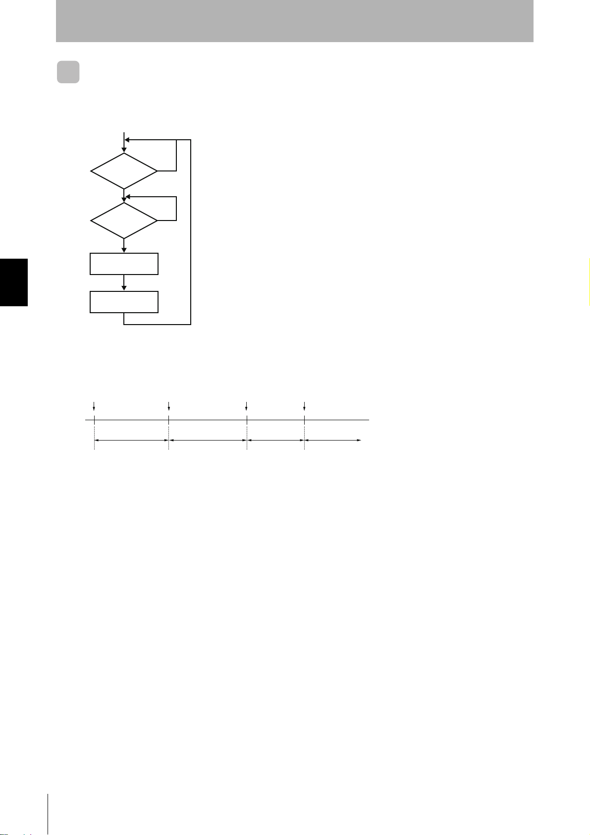
SECTION 4
Functions
Trigger Input
There is one trigger input for each Antenna (two total) which can be used to tell the ID Controller when
to start Tag processing. Once the ID Controller has received a command, it will wait for the rising edge
of the trigger input and then communicate with the Tag.
SECTION 4
Trigger Input
Command
received?
Trigger
input active?
N
Y
N
Note: Processing is not stopped even if the trigger input changes during
command processing.
Y
Command
processed
Response
processed
If auto commands are used, the ID Controller will wait from the rising edge of the Trigger input for a Tag
to enter the communications area. This means that read/write processing will not start after a command is received until the rising edge of the trigger input, even if a Tag approaches.
Auto command received Trigger input goes active Tag approaches Response sent
Waiting for trigger
input (See note.)
Waiting for Tag to
approach
Waiting for Tag
communications
Waiting to receive
a command
Note: Read/write processing will not start while the ID Controller is waiting for the trigger input, even if
a Tag approaches.
80
RFID System
User’s Manual
Page 84

SECTION 4
Functions
Write Protection
Write protection can be set to protect important data stored in the memory of an ID Tag, such as product numbers and models from being mistakenly overwritten. After important data has been written to memory, it can
be write-protected using the following method.
The write protection function is supported only for these OMRON ID Controllers. It is not valid for Reader/Writers manufactured
by other companies.
Setting Write Protection
The ID Controller and ID Tag each have enable and disable settings for write protection. Always make
the settings in both the ID Controller and ID Tag when setting write protection.
Also, the memory map for ID Tag write protection settings differs when using V680 commands and
V600 commands. Use the settings that match the command being used.
SECTION 4
Setting Write Protection When Using V680 Commands
1. Set the write protection setting of the ID Controller to “Enable.”
• Using the DIP Switch (when pin 1 on SW3 is set to OFF):
Pin 7 on SW4: Set write protection to “OFF” to enable write protection.
• Using the Internal Setting (when pin 1 on SW3 is set to ON):
PARAMETER SET (SP) COMMAND processing code “H”: Set the write protection setting to “01” to
enable write protection.
Write protection is enabled as the default setting.
For details on the PARAMETER SET (SP) COMMAND, refer to Command and Response Formats.
p.175
Write Protection
RFID System
User’s Manual
81
Page 85

SECTION 4
Write Protection
SECTION 4
Functions
2. Set the write protection setting of the ID Tag.
When the start address and end address for write protection are written into ID Tag address 0000H to
0003H, the area from the start address to the end address is write-protected. The most significant bit of
address 0000H is used to enable or disable write protection.
Memory Map for ID Tag Write Protection Settings
Address Bit 7 6 5 4 3 2 1 0
H
0000
0001
H Lower two digits of start address (00 to FF)
H Upper two digits of end address (00 to FF)
0002
0003
H Lower two digits of end address (00 to FF)
• Most Significant Bit of Address 0000
1: Write-protected (Enabled)
0: Not write-protected (Disabled)
Enable/
disable
Upper two digits of start address (00 to 7F)
H
• Area in Tag Memory That Can Be Write Protected
Start address: 0004
H to 7FFFH
End address: 0004H to FFFFH
To use write protection, use one operation to write to the write protection setting area (addresses 0000H to 0003H) and a separate operation to write to other addresses (address 0004
significant bit of address 0000
settings area and other addresses in the ID Tag.
When write protection is not set in the write protection setting area (addresses 0000
setting area can be used for user memory. When the write protection setting area of the ID Tag is used for user memory, be sure
to disable the write protection setting of the ID Controller.
H is 1 and a write operation is performed that includes both addresses in the ID tag write protection
H or higher) in the ID Tag. A write protection error will occur if the most
H to 0003H) of the ID Tag, the write protection
82
RFID System
User’s Manual
Page 86

Example of Write Protection
Start Address Is Lower Than the End Address
The memory area between the start address and end address will be write-protected.
0000
H
Address Bit Upper digits Lower digits
1
0000
0001
0002
0003
H
H
H
H
0000000
80
00010101
15
00000001
01
00100000
20
Start Address Is Equal to End Address
Only the selected address (one byte) will be write-protected.
(Hex)
0015
0120
03E7
H
H
H
SECTION 4
Functions
Writeprotected
SECTION 4
Write Protection
0000
H
Address Bit Upper digits Lower digits
1
0000
0001
0002
0003
H
H
H
H
0000000
80
00100001
21
00000000
00
00100001
21
(Hex)
0021
03E7
H
Writeprotected
H
End Address Is Higher than the Last ID Tag Address
The memory area between the start address and the last ID Tag address will be write-protected.
0000
H
Address Bit Upper digits Lower digits
1
0000
0001
0002
0003
H
H
H
H
0000011
83
00000000
00
00000011
03
11111111
FF
(Hex)
0300
03E7
H
H
Writeprotected
The write protection setting area of the ID Tag cannot be write-protected.
RFID System
User’s Manual
83
Page 87

SECTION 4
Write Protection
SECTION 4
Functions
Start Address Is Higher Than End Address
The memory area between the start address and the last ID Tag address, as well as the area between
0004H and the end address will be write-protected.
Address Bit Upper digits Lower digits
1
0000
0001
0002
0003
H
H
H
H
0000001
81
00100000
20
00000000
00
00010101
15
0000H
0004H
Write-protected area
Last address
0015H
Start address
0120H
Write-protected area
03E7H
The write protection setting area of the ID Tag cannot be write-protected.
Disabling Write Protection When Using V680 Commands
Disabling ID Tag Write Protection for Part of the Area Being Used:
To temporarily disable write protection when you want to, for example, rewrite data that is being writeprotected, set the most significant bit of address 0000H for the ID Tag memory to “0.”
Disabling Write Protection for all OMRON-made RFID systems:
To disable write protection in order to, for example, use the entire memory area of the ID Tag as user
memory, use either of the following methods to set all of the ID Controllers.
• Using the DIP Switch (when pin 1 on SW3 is set to OFF):
Pin 7 on SW4: Set write protection to “ON” to disable write protection.
• Using the Internal Setting (when pin 1 on SW3 is set to ON):
PARAMETER SET (SP) COMMAND processing code “H”: Set the write protection setting to ”00” to
disable write protection.
84
RFID System
User’s Manual
Precautions on Using Write Protection
The write protection function is supported only for these OMRON ID Controllers. It is not valid for reader/writers manufactured by other companies.
Page 88

SECTION 4
Functions
For details on the PARAMETER SET (SP) COMMAND, refer to Command and Response Formats.
p.175
Setting Write Protection When Using V600 Commands
There are separate write protection setting methods for the EEPROM (Battery-less) Data Carrier
(V600-D23P@@) and the S-RAM (Built-in Battery) Data Carrier of the V600 Series.
When using V600 commands with a V680-series ID Controller, the conventional write protection setting method can be used by selecting the ID Controller internal setting and the ID Tag type.
- EEPROM Data Carrier: For the V680-D1KP@@, use the V600 EEPROM write protection method.
- F-RAM Data Carrier: For the V680-D2K/8K/32KF@@, use the V600 S-RAM write protection method.
The ID Controller automatically switches between the V600 EEPROM write protection method and the V600 S-RAM
write protection method according to the ID Tag being used, so the user does not need to make this setting.
SECTION 4
The V600 EEPROM write protection method and the V600 S-RAM write protection method can be used only on ID Controllers that are version 2.1 or newer. For details on Checking the Version, refer to page 17.
To set the same ID Tag write protection setting area for EEPROM and F-RAM, use the V680 write protection method.
1. Set the write protection setting of the ID Controller to “Enable.”
• Using the DIP Switch (when pin 1 on SW3 is set to OFF):
Pin 7 on SW4: Set write protection to “OFF” to enable write protection.
• Using the Internal Setting (when pin 1 on SW3 is set to ON):
PARAMETER SET (SP) COMMAND processing code “H”: Set the write protection setting to “1” to
enable write protection.
Write protection is enabled as the default setting.
For details on the PARAMETER SET (SP) COMMAND, refer to Command and Response Formats.
Write Protection
p.175
2. Set the Write Protection Method
INTERNAL SET (SP) COMMAND processing code “J”: Set to either the V600 write protection method
or the V680 write protection method.
For details on the PARAMETER SET (SP) COMMAND, refer to Command and Response Formats.
p.175
RFID System
User’s Manual
85
Page 89

SECTION 4
Write Protection
SECTION 4
Functions
3. Set the write protection setting of the ID Tag.
Setting Write Protection for V600 EEPROM Models
(Setting the V600 Write Protection Method and Using the V680-D1KP@@)
When the end address for write protection is written into ID Tag address 0000H, the area from address
0001H to the end address is write-protected.
The most significant bit of ID Tag address 0000H is used to enable or disable write protection.
For this reason, addresses from 0080H to 03E7H cannot be used as end addresses.
When the end address is set to 00, the area from address 0001H to 03E7 is write-protected.
The V600 EEPROM write protection method and the V600 S-RAM write protection method can be used only on ID Controllers that are version 2.1 or newer. For details on Checking the Version, refer to page 17.
Memory Map for V600 EEPROM ID Tag Write Protection Settings
Address Bit 7 6 5 4 3 2 1 0
0000
H
Enable/
disable
End address
• Most Significant Bit of Address 0000
H
1: Write-protected (Enabled)
0: Not write-protected (Disabled)
• Area in Which the End Address Can Be Set
End address: 00H, 01H to 7FH
To use write protection, one operation to write to the write protection setting area (address 0000H) and a separate operation to write to other addresses (address 0001
bit of address 0000
settings area and other addresses in the ID Tag.
H is 1 and a write operation is performed that includes both addresses in the ID tag write protection
H hex or higher). A write protection error will occur if the most significant
Example of Write Protection
Write Protecting Addresses 0001
Address Bit 7 6 5 4 3 2 1 0
0000
H
10010010
92
H to 0012H
Setting 00 as the End Address
All addresses except address 0000
Address Bit 7 6 5 4 3 2 1 0
0000
H
10000000
80
H will be write-protected.
Address
Address
0000
0012
03E7
0000
H
Writeprotected
area
H
H
H
Writeprotected
area
86
RFID System
User’s Manual
The write protection setting area of the ID Tag cannot be write-protected.
03E7
H
Page 90

SECTION 4
Functions
Setting Write Protection for V600 S-RAM Model
(Setting the V600 Write Protection Method and Using the V680-D2K/8K/32K@@)
When the start address and end address for write protection are written into ID Tag addresses 0002H
to 0005H, the area from the start address to the end address is write-protected.
The most significant bit of address 0002H is used to enable or disable write protection.
In V600 S-RAM write protection, addresses 0000H and 0001H are always write-protected regardless of
whether write protection is enabled or disabled.
The V600 EEPROM write protection method and the V600 S-RAM write protection method can be used only on ID Controllers that are version 2.1 or newer. For details on Checking the Version, refer to page 17.
Memory Map for V600 S-RAM ID Tag Write Protection Settings
Address Bit 7 6 5 4 3 2 1 0
0002
H
0003
H Lower two digits of start address (00 to FF)
H Upper two digits of end address (00 to FF)
0004
0005
H Lower two digits of end address (00 to FF)
Enable/
disable
Upper two digits of start address (00 to 7F)
SECTION 4
Write Protection
• Most Significant Bit of Address 0002
H
1: Write-protected (Enabled)
0: Not write-protected (Disabled)
• Area in ID Tag Memory That Can Be Write Protected
Start address: 0006H to 7FFFH
End address: 0006H to FFFFH
To use write protection, one operation to write to the write protection setting area (addresses 0002H to 0005H) and a
separate operation to write to other addresses (address 0006
significant bit of address 0002
protection settings area and other addresses in the ID Tag.
H is 1 and a write operation is performed that includes both addresses in the ID tag write
H or higher). A write protection error will occur if the most
RFID System
User’s Manual
87
Page 91

SECTION 4
d
Functions
Example of Write Protection
Start Address Lower Than the End Address
The memory area between the start address and end address will be write-protected.
Address Bit Upper digits Lower digits
0002
0003
0004
0005
H
H
H
H
10000000
80
00010101
15
00000001
01
00100000
20
Address
0000
0015
0120
H
H
H
Writeprotected
area
SECTION 4
Write Protection
7FFF
H
Start Address Equal to End Address
Only the selected address (one byte) will be write-protected.
Address Bit Upper digits Lower digits
0002
0003
0004
0005
H
H
H
H
10000000
80
00100001
21
00000000
00
00100001
21
Address
0000
0021
7FFF
H
H
H
Writeprotecte
area
End Address Higher than Last ID Tag Address
The memory area between the start address and the last ID Tag address will be write-protected.
Address Bit Upper digits Lower digits
0002
0003
0004
0005
H
H
H
H
10000011
83
00000000
00
11111111
FF
11111111
FF
Address
7FFF
0000
0300
H
H
H
Writeprotected
area
88
RFID System
User’s Manual
The write protection setting area of the ID Tag cannot be write-protected.
Addresses 0000
H and 0000H are always write-protected, regardless of the setting of the write protection function.
Page 92

SECTION 4
Functions
Start Address Higher Than End Address
The memory area between the start address and the last ID Tag address, as well as the area between
0006H and the end address will be write-protected.
Address Bit Upper digits Lower digits
0002
0003
0004
0005
H
H
H
H
10000001
81
00100000
20
00000000
00
00010101
15
Address
0000
H
0006
H
Last address
0015
H
Writeprotected
area
SECTION 4
Write Protection
End address
0120
7FFF
H
Writeprotected
area
H
The write protection setting area of the ID Tag cannot be write-protected.
Addresses 0000
H and 0001H are always write-protected, regardless of the setting of the write protection function.
RFID System
User’s Manual
89
Page 93

SECTION 4
Write Protection
SECTION 4
Functions
Setting Write Protection for V680 Models
The same method is used as that for setting ID Tags when using V680 commands. Refer to step 2 (Set
the write protection function of the ID Tag) of Setting Write Protection when Using V680 Commands.
Disabling Write Protection When Using V600 Commands
Disabling ID Tag write protection for part of the area being used:
To temporarily disable write protection when you want to, for example, rewrite data that is being writeprotected, set the most significant bit of the following address for the ID Tag memory to “0.”
- V600 EEPROM write protection Address 0000H
- V600 S-RAM write protection Address 0002H
- V600 write protection Address 0000H
Disabling Write Protection for all OMRON-made RFID Systems:
To disable write protection in order to, for example, use the entire memory area of the ID Tag as user
memory, use either of the following methods to set all of the ID Controllers.
• Using the DIP Switch (when pin 1 on SW3 is set to OFF):
Pin 7 on SW4: Set the write protection setting to “ON” to disable write protection.
• Using the internal setting (when pin 1 on SW3 is set to ON):
PARAMETER SET (SP) COMMAND processing code “H”: Set the write protection setting to “00” to
disable write protection.
Precautions on Using Write Protection
The write protection function is supported only for these OMRON ID Controllers. It is not valid for reader/writers manufactured by
other companies.
For details on the PARAMETER SET (SP) COMMAND, refer to Command and Response Formats.
p.175
90
RFID System
User’s Manual
Page 94

SECTION 4
Functions
Tag Service Life Check
The OVERWRITE COUNT CONTROL command (MDS/MDL) can be used to determine whether the Tag
overwrite limit has been exceeded. With the MDS command, the overwrite count is subtracted from the data in
the user-specified overwrite count control area to determine whether the number of overwrites has been
exceeded. The MDL command can also be used to determine whether the overwrite count (100,000 times)
has been exceeded. The overwrite count is added to the data in the user-specified overwrite count control
area to determine whether 100,000 overwrites has been exceeded.
MDS Command
The overwrite count control area consists of 3 bytes from the specified start address. The decrement
value from the overwrite count is written in this area, and if this value is 0 (00 hex), an end code 76 will
be given as a warning. Therefore, to enable control of the number of overwrites, the maximum number
of overwrites must be written to the overwrite count control area beforehand.
The user-specified number of overwrites can be set to up to 16,700,000. The overwrite life of EEPROM
ID Tags is 100,000 (0186A0 hex) at 25
less. The number of overwrites is written to the control area using a hexadecimal value, and can be
read using the READ command.
If the control area data is already 0, the control area value will not be refreshed, and only a warning will
be returned as a response. When the refresh count is set as 00 hex, the count will not be updated, and
only an overwrite count check will be performed.
°C or lower. Set the maximum number of overwrites to 100,00 or
SECTION 4
Tag Service Life Check
For details on the command format, refer to OVERWRITE
COUNT CONTROL (MD S/L).
p. 123
Area start address
Example Using the OVERWRITE COUNT
(MDS) Command
The overwrite count control area consists of 3 bytes starting from address 0010H.
1)
The overwrite count of 100,000 times is written.
“WTSTH100100186A0”
0010
0011
0012
3)The following memory status will exist after the
accumulated decremented count is 100,000 times.
If “MDSTS1001000” is executed now, “MD76”
(overwrite count exceeded) will be returned.
01H
86H
A0H
2) The overwrite count of 5 is written.
“MDSTS1001005”
The count is decremented 5 times from 100,000 to
produce the following.
0010
0011
0012
01H
86H
9BH
Upper digit
Middle digit
Lower digit
3 bytes
0010
0011
0012
00H
00H
00H
RFID System
User’s Manual
91
Page 95

SECTION 4
SECTION 4
Functions
MDL Command
The overwrite count control area consists of 3 bytes from
the specified start address. The increment value from the
overwrite count is written to this area, and if this value is
100,000 (0186A0 hex) or higher, an end code of 76 will be
given as a warning. The number of overwrites is controlled using a hexadecimal value, and can be read using
the READ command.
If the control area data is already 100,000 or higher, the
control area value will not be refreshed, and only a warning will be returned as a response. When the refresh
count is set as 00 hex, the count will not be updated, and
only an overwrite count check will be performed.
For details on the command format, refer to OVERWRITE COUNT CONTROL (MD S/L).
Area start address
Upper digit
Middle digit
Lower digit
3 bytes
Tag Service Life Check
p. 123
Example Using Overwrite Count Control Command (MDL)
In the following example, the three bytes starting from address 0010H is the overwrite count control
area.
1)The control area is cleared.
“WTSTH10010000000”
0010
0011
0012
3)Next, the overwrite count of 5 is entered.
“MDSTL1001005”
The total overwrite count becomes 9 times.
0010
0011
0012
Do not execute the MDS command and MDL command for the same Tag. Doing so will prevent managing the service life.
00H
00H
00H
00H
00H
09H
2)The overwrite count of 4 is entered.
“MDSTL1001004”
0010
0011
0012
4)The following memory status will exist after the
accumulated count has reached 100,000 times.
If “MDSTS1001000” is executed now, “MD7610”
(overwrite count exceeded) will be returned.
0010
0011
0012
00H
00H
04H
01H
86H
A0H
92
RFID System
User’s Manual
Page 96

SECTION 4
k
Functions
Tag Memory Check
The DATA CHECK command (MD C/K) performs a memory check. A CRC (Cyclic Redundancy Check) code
calculation, write, and comparison are made using the check block unit specified by the user.
The CRC code is calculated from the generated polynomial expression x
16
12
+ x
+ x5 + 1.
The calculation area is the portion of the check block
specified by the start address and the number of bytes
excluding the last two bytes. The last two bytes are the
check code area.
When check code write is specified (process designation:
K), the CRC of the calculation area data is calculated and
written to the check code area. When data comparison is
specified (process designation: C), the CRC of the calculation area data is calculated and a comparison made
with the check code area data. If they coincide, an end
code of 00 will be returned for the V680 command (75
will be returned for the V600 command), and if they do
not coincide, an end code of 76 will be returned as a
warning.
For details on the command format, refer to DATA CHECK (MD
C/K).
p. 125
Address
Area start
address
Number of check
block bytes
0000
0001
CRC (leftmost)
CRC (rightmost)
Check code
calculation area
(Number of chec
block bytes −2)
Check code area
(2 bytes)
SECTION 4
Tag Memory Check
Example of Tag Memory Check
In the following example, the data in address 0010H to 0012H is checked.
1) In this example, the following data already exists in
the memory.
0010
0011
0012
0013
0014
12H
34H
56H
3)Execute MDSTC1001005 (code verification).
The normal response MD0010 will be returned if the
data coincides.
0010
0011
0012
0013
0014
12H
34H
56H
5CH
D6H
2) Execute MDSTK1001005 (code calculation).
The CRC code 5CD6 calculated from the data
123456 is written to addresses 0013
0010
0011
0012
0013
0014
If a data error occurs, MD7610 (a data error warning)
will be returned.
0010
0011
0012
0013
0014
12H
34H
56H
5CH
D6H
00H
34H
56H
5CH
D6H
H and 0014H.
Data error
RFID System
User’s Manual
93
Page 97

SECTION 4
Tag Memory Error Correction
SECTION 4
Functions
Tag Memory Error Correction
The WRITE TAG MEMORY ERROR CORRECTION (QW) command writes a tag memory check and 5-byte
error correct code after the write data. The READ TAG MEMORY ERROR CORRECTION (QR) command
performs a tag memory check and makes 1-bit memory error corrections.
Address
When a 1-bit memory error is corrected, an
end code of 77 will warn that a 1-bit memory
error occurred, and the normal data with the
error corrected will be returned.
When a memory error of 2 bits or more is
detected, an end code of 76 will warn that a
fatal error occurred, and the read data will
not be returned.
Area start
address
Area end
address
0000
0001
Memory check code (leftmost)
Memory check code (rightmost)
Error correct code (leftmost)
Error correct code (mid)
Error correct code (rightmost)
Check code
calculation area
Error correction
code calculation
area
For details on the command format, refer to READ TAG MEMORY ERROR CORRECTION (QR) and WRITE TAG MEMORY
ERROR CORRECTION (QW).
p. 136, p. 138
Example of Tag Memory Error Correction
In the following example, the data in address 0010H to 0015H is checked.
1) Send WRITE TAG MEMORY ERROR CORRECTION (QW).
Command: QWSTH10010313233343536 * (CR)
3)Send READ TAG MEMORY ERROR CORRECTION
(QR).
Command: QRSTH100100006 * (CR)
2) Data is written to address 0010
H to 0015H, then a tag
memory check and 5-byte error correct code are written to address 0016
Address
0010
0011
0012
0013
0014
0015
0016
0017
0018
0019
001A
31
32
33
34
35
36
FD
11
00
0C
3C
H to 001AH.
Write data
(check code
calculation
area)
Memory check code (leftmost)
Memory check code (rightmost)
Error correct code (leftmost)
Error correct code (mid)
Error correct code (rightmost)
94
• When the read data coincides:
Response: QR0010313233343536 * (CR)
• When a memory error of 2 bits or more is
detected:
Response: QR76 * (CR)
RFID System
User’s Manual
• When a 1-bit memory error is corrected:
Response: QR7710313233343536 * (CR)
Page 98

Write Command Memory
A write command executed by the V680-CA5D01/02 ID Controller is stored in memory until the next
write command is executed or until the power is reset. Write commands include WRITE, EXPANSION
WRITE, AUTO WRITE, and POLLING AUTO WRITE. The write command stored in memory can be
executed using the WRITE REPEAT (RP) command.
Operation
Power ON
Memory
SECTION 4
Functions
ID Controller
Operation
Memory initialized
WRITE command 1
WRITE REPEAT command
Read command 1
WRITE REPEAT command
WRITE command 2
WRITE command 1
WRITE command 1
WRITE command 1
WRITE command 1
WRITE command 2
WRITE command 1 executed
WRITE command 1 executed
READ command 1 executed
WRITE command 1 executed
WRITE command 2 executed
SECTION 4
Write Command Memory
RFID System
User’s Manual
95
Page 99

SECTION 4
SECTION 4
Functions
Noise Monitor Function
When executing commands for Tag communications, the maximum value of the noise level can be
attached to the response data to constantly monitor noise conditions.
The noise monitor function cannot be used when the V680-H01 Antenna is connected.
To use the noise monitor function it must be enabled using the PARAMETER SET (SP) command.
p. 147
Response Examples
● Noise Monitor Function Enabled
RD 00 1 0
......
[01] * CR
Noise Monitor Function
Maximum noise level ("01" to "99")
Read data
Resend Flag (Always "0".)
Antenna channel ("1": channel 1, "2": channel 2)
End code
● Noise Monitor Function Disabled
RD 00 1 0
......
* CR
Read data
Resend Flag (Always "0".)
Antenna channel ("1": channel 1, "2": channel 2)
End code
96
RFID System
User’s Manual
Page 100

SECTION 5 Communications
Tag Operation and Command Status 98
V600-V680 Command Correspondence 101
V680 Commands 103
V600 Commands 172
SECTION 5
Communications
RFID System
User’s Manual
97
 Loading...