


Electromagnetic Inductive RFID System
V670 Series
User’s Manual
ID Controller, Antenna, and ID Tag
ID Controller
Model V670-CD1D-V1
Antenna
Model V670-H11
Model V670-H51
Model V670-H51Q
ID Tag
Model V670-D13F03
Model V670-D13F01
Model V670-D13F01H
Catalog No. Z148-E1-02

Introduction
We sincerely appreciate your purchase of the V670 series of the Electromagnetic Induction Type RFID System. The V670 series is fully
supported by our cutting-edge technology and vast expertise. This user's manual provides vital information on its operational functions
and product performances, and includes full instructions for use.
Read and Understand this user’s manual
Please read and understand this instruction manual before storing, installing, programming, operating, maintaining, or disposing of
the products. Please consult your OMRON representative if you have any questions or comments.
Warranty and Limitations of Liability
WARRANTY
OMRON's exclusive warranty is that the products are free from defects in materials and workmanship for a period of one year (or
other period if specified) from date of sale by OMRON.
OMRON MAKES NO WARRANTY OR REPRESENTATION, EXPRESS OR IMPLIED, REGARDING NON-INFRINGEMENT, MERCHANTABILITY, OR FITNESS FOR PARTICULAR PURPOSE OF THE PRODUCTS. ANY BUYER OR
USER ACKNOWLEDGES THAT THE BUYER OR USER ALONE HAS DETERMINED THAT THE PRODUCTS WILL
SUITABLY MEET THE REQUIREMENTS OF THEIR INTENDED USE. OMRON DISCLAIMS ALL OTHER WARRANTIES, EXPRESS OR IMPLIED.
LIMITATIONS OF LIABILITY
OMRON SHALL NOT BE RESPONSIBLE FOR SPECIAL, INDIRECT, OR CONSEQUENTIAL DAMAGES, LOSS OF
PROFITS OR COMMERCIAL LOSS IN ANY WAY CONNECTED WITH THE PRODUCTS, WHETHER SUCH CLAIM IS
BASED ON CONTRACT, WARRANTY, NEGLIGENCE, OR STRICT LIABILITY.
In no event shall the responsibility of OMRON for any act exceed the individual price of the product on which liability is
asserted.
IN NO EVENT SHALL OMRON BE RESPONSIBLE FOR WARRANTY, REPAIR, OR OTHER CLAIMS REGARDING
THE PRODUCTS UNLESS OMRON'S ANALYSIS CONFIRMS THAT THE PRODUCTS WERE PROPERLY HANDLED,
STORED, INSTALLED, AND MAINTAINED AND NOT SUBJECT TO CONTAMINATION, ABUSE, MISUSE, OR INAPPROPRIATE MODIFICATION OR REPAIR.
Application Considerations
SUITABILITY FOR USE
OMRON shall not be responsible for conformity with any standards, codes, or regulations that apply to the combination of products in the customer's application or use of the products.
At the customer's request, OMRON will provide applicable third party certification documents identifying ratings and limitations
of use that apply to the products. This information by itself is not sufficient for a complete determination of the suitability of the
products in combination with the end product, machine, system, or other application or use.
The following are some examples of applications for which particular attention must be given. This is not intended to be an
exhaustive list of all possible uses of the products, nor is it intended to imply that the uses listed may be suitable for the
products:
• Outdoor use, uses involving potential chemical contamination or electrical interference, or conditions or uses not described in
this instruction manual.
• Nuclear energy control systems, combustion systems, railroad systems, aviation systems, medical equipment, amusement
machines, vehicles, safety equipment, and installations subject to separate industry or government regulations.
• Systems, machines, and equipment that could present a risk to life or property.
Please know and observe all prohibitions of use applicable to the products.
NEVER USE THE PRODUCTS FOR AN APPLICATION INVOLVING SERIOUS RISK TO LIFE OR PROPERTY WITHOUT ENSURING THAT THE SYSTEM AS A WHOLE HAS BEEN DESIGNED TO ADDRESS THE RISKS, AND THAT
THE OMRON PRODUCTS ARE PROPERLY RATED AND INSTALLED FOR THE INTENDED USE WITHIN THE OVERALL EQUIPMENT OR SYSTEM.
PROGRAMMABLE PRODUCTS
OMRON shall not be responsible for the user's programming of a programmable product, or any consequence thereof.
Disclaimers
PERFORMANCE DATA
Performance data given in this manual is provided as a guide for the user in determining suitability and does not constitute a warranty. It may represent the result of OMRON’s test conditions, and the users must correlate it to actual application requirements.
Actual performance is subject to the OMRON Warranty and Limitations of Liability.
CHANGE IN SPECIFICATIONS
Product specifications and accessories may be changed at any time based on improvements and other reasons.
It is our practice to change model numbers when published ratings or features are changed, or when significant construction
changes are made. However, some specifications of the products may be changed without any notice. When in doubt, special
model numbers may be assigned to fix or establish key specifications for your application on your request. Please consult with
your OMRON representative at any time to confirm actual specifications of purchased products.
DIMENSIONS AND WEIGHTS
Dimensions and weights are nominal and are not to be used for manufacturing purposes, even when tolerances are shown.
ERRORS AND OMISSIONS
The information in this instruction manual has been carefully checked and is believed to be accurate; however, no responsibility
is assumed for clerical, typographical, or proofreading errors, or omissions.
The following signal words are used in this instruction manual.
The following alert symbols are used in this instruction manual.
The following alert statements apply to the products in this instruction manual. Each alert statement also appears at the locations needed
in the manual to attract your attention.
Meaning of Signal Words
CAUTION
Indicates a potentially hazardous situation which, if not avoided, may result in minor or
moderate injury or in property damage.
Meaning of Alert Symbols
Indicates the possibility of electric shock under specific conditions.
Alert Statement in this user’s Manual
CAUTION
When you plug or unplug the connector into the programming console when the power supply turns on, take care not to
touch the controller wire. Otherwise, you may get an electric shock.

For the safety, be sure to follow the instructions below:
1. Do not operate this device in any flammable, explosive or corrosive gas environment.
2. Do not disassemble, repair nor remodel this device.
3. Tighten the base lock screws and terminal block screws completely.
4. Be sure to use wiring crimp terminal of a specified size.
5. If any cable has a locking mechanism, be sure to check that it has been locked before using it.
6. The DC power supply must meet the following items:
(1) Such DC power supply must be used for the V670 Series only and must not be connected to any other devices nor apparatuses.
(2) Voltage of such DC power supply must be within the specified rating (24 VDC+10%-10%).
7. Be sure to follow any other warnings, cautions and notices mentioned in this manual.
8. In the event that the system gives out a foul smell, is heated abnormally in the main body portion, emits smoke, or exhibits any other
abnormal condition, immediately stop using the system and turn off the power.
9. Dispose of this product as industrial waste.
Please observe the following precautions to prevent failure to operate, malfunctions, or undesirable effects on product performance.
♦ System Construction
• In consequence of diversification of small-size antennas/tags, the ID controller has been upgraded to Model V670-CD1D-V1. Be
sure to combine Model V670-H51 or Model V670-H51Q antenna with Model V670-CD1D-V1 controller. Combination of this
antenna with Model V670-CD1D controller might result in unstable communication.
♦ Installation Site
Install the product at a location where:
• It is not exposed to corrosive gases, dust, metal chips, or salt.
• The working temperature is within the range stipulated in the specifications.
• There are no sudden variations in temperature (no condensation).
• The relative humidity is within the range stipulated in the specifications.
• No vibration or shock exceeding the values stipulated in the specifications is transmitted directly to the body of the product.
• It is not subject to splashing water, oil, or chemical substances.
♦ Installation
• This device uses the frequency band 13.56 MHz to communicate with a tag. This frequency band 13.56 MHz is used also as the
ISM band (one of frequencies assigned to medical or industrial heater; ). So, such heater may affect the communication with a tag
or may damage the tag, if the heater is located near this device. If you must use this device near such heater, we would like you to
check the influence in advance.
• To minimize general influence of noise, follow the instructions below:
(1) Ground any metallic material located around this device according to Class D (Class III).
(2) Wire this device keeping away from high voltage and heavy current.
• Connectors are not waterproof. Avoid using the product in a humid environment.
• Do not use any chemical that may affect the materials of the product.
♦ Cleaning
• Do not use any thinner. Resin material and case paint are dissolved by thinner.
Precautions for safe use.
Precautions for correct use.
1. FCC Rules (Federal Communications Commission)
This Product complies with Part 15 Subpart C of the FCC Rules.
FCC ID: E4E6CYCIDV6700101
FCC NOTICE
This equipment has been tested and found to comply with the limits of a Class A digital device, pursuant to part 15 of the FCC Rules.
These limits are designed to provide reasonable protection against harmful interference when the equipment is operated in a commercial environment. This equipment generates, uses, and can radiate radio frequency energy and, if not installed and used in accordance
with the instruction manual, may cause harmful interference to radio communications. Operation of this equipment in a residential
area is likely to cause harmful interference in which case the user will be required to correct the interference at his own expense.
FCC WARNING
Changes or modifications not expressly approved by the party responsible for compliance could void the user's authority to operate
the equipment.
Properly shielded ground cables and connectors must be used for connection to host computer and/or peripherals in order to meet
FCC emission limits.
AC adaptor with ferrite core must be used for RF interference suppression.
2. EC Declaration of Conformity
Hereby, OMRON Corporation declares that this RFID System, Antenna V670-H11, V670-H51, V670-H51Q and Controller V670CD1D-V1. Controller are in compliance with essential requirements and other relevant provisions of Directive 1995/5/EC, and satisfy tests for the appropriate requirements of the following relevant standards.
Radio: EN 300 330-2 V1.1.1 (06-2001) EN 300 300-1 V1.3.1 (06-2001)
EMC: EN 301 489-3 V1.4.1 (08-2002) EN 301 489-1 V1.4.1 (08-2002)
Safety: EN 61010-1: 2001 (2nd Edition)
Countries of intended use:
Austria, Belgium, Denmark, Estonia, Finland, France, Germany, Greece, Iceland, Ireland, Italy, Liechtenstein, Luxembourg, Netherlands, Norway, Portugal, Spain, Sweden, Switzerland, United Kingdom
Standard Conformity
English
Hereby, Omron, declares that the RFID System, Antenna V670-H11 Series, V670-H51 Series, V670-H51Q Series, and Controller
V670-CD1D Series are in compliance with the essential requirements and other relevant provisions of Directive 1999/5/EC.
Finnish
Omron vakuuttaa täten että RFID Säännös, Antenni V670-H11 Series, V670-H51 Series, V670-H51Q Series, jar Kontrollida V670CD1D Series tyyppinen laite on direktiivin 1999/5/EY oleellisten vaatimusten ja sitä koskevien direktiivin muiden ehtojen mukainen.
Dutch
Hierbij verklaart Omron dat het toestel de RFID Systeem, Antenne V670-H11 ´Serie, V670-H51 ´Serie, V670-H51Q ´Serie, en Controleur V670-CD1D ´Serie in overeenstemming is met de essentiële eisen en de andere relevante bepalingen van richtlijh 1999/5/EG.
French
Par la présente Omron déclare que la RFID Système, Antenne V670-H11 Série, V670-H51 Série, V670-H51Q Série, et Contrôler
V670-CD1D Série sont conforme aux exigences essentielles et aux autres dispositions pertinentes de la directive 1999/5/CE.
Swedish
Härmed intygar Omron att den RFID System, Antenn V670-H11 Serie, V670-H51 Serie, V670-H51Q Serie, och Kontrollant V670CD1D Serie stär l överensstämmelse med de väsentliga egenskapskrav och övriga relevanta bestämmelser som framgår av direktiv
1999/5/EG.
Danish
Undertegnede Omron erklærer herved, at følgende den RFID System, Antenne V670-H11 Serie, V670-H51 Serie, V670-H51Q Serie,
og Kontrollør V670-CD1D Serie overholder de væsentlige krav og øvrige relevante krav i direktiv 1999/5/EF.
Germen
Hiermit erklärt Omron, die RFID System, Antenne V670-H11 Serie, V670-H51 Serie, V670-H51Q Serie, und Kontrolleur V670CD1D Serie in Übereinstimmung mit den grundlegenden Anforderungen und den anderen relevanten Vorschriften der Richtlinie
1999/5/EG befindet. (BMWi)
Greek
ME THN ΠAPOYSA Omron ∆HΛONEI RFID O’YO’ΓΗΜΑ, KEPAIA V670-H11 O’EIPA, V670-H51Q O’EIPA, KAI KOYPOΛHPΨ
V670-CD1D O’EIPA SYMMOPF ONETAI ΠPOS TIS OYSIO∆EIS AΠAITHSEIS KAI TIS ΛOIΠES SXETIKES ∆IATAΞEIS THS
O∆HΓIAS 1999/5/EK.
Italian
Con la presente Omron dichiara che la RFID Sistema, Antena V670-H11Serie, V670-H51 Serie, V670-H51Q Serie, e Controlleur
V670-CD1D Serie sono conforme ai requisiti essenziali ed alle altre disposizioni pertinenti stabilite dalla direttiva 1999/5/CE.
Spanish
Por medio de la presente Omron declara que el RFID Sistema, Antena V670-H11 Serie, V670-H51 Serie, V670-H51Q Serie, y Controlador V670-CD1D Serie esta conforme a los requisitos esenciales y cualesquiera otras disposiciones aplicables o exigibles de la
Directiva 1999/5/CE.
Portuguese
Omron declara que a RFID Sistema, Antena V670-H11 Série, V670-H51 Série, V670-H51Q Série, e Controlador V670-CD1D Série
ser conforme com os tequisitos essenciais e outras disposições da Directiva 1999/5/CE.
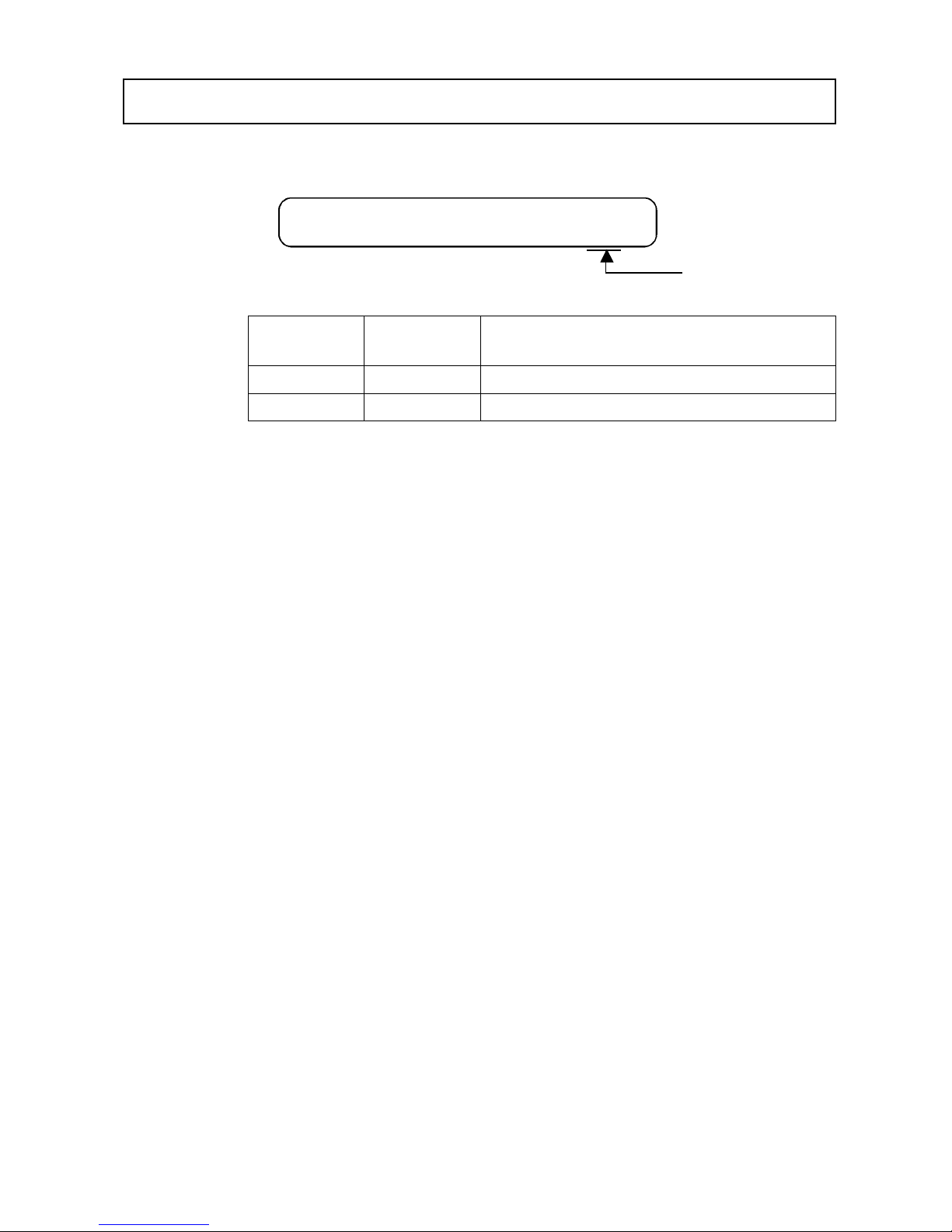
A manual revision history code is added to the end of catalog number shown at the left lower part of front cover
and back cover
Manual Revision History
Revision
Code
Date of
Revision
Reason of Revision / Revised Page
-- October 2000 First Edition
-02 May 2003 New models have been added.
Catalog No. Z148-E1-01
Revision code

Contents
Chapter 1 Features and System Configuration
1-1 Features .........................................................................................................................1-1
1-2 System Configuration.....................................................................................................1-3
Chapter 2 Specifications and Performance
2-1 Controller........................................................................................................................2-1
2-1-1 Component Names and Functions .....................................................................................................2-1
2-1-2 General Specifications .......................................................................................................................2-3
2-1-3 Performance Specifications................................................................................................................2-3
2-1-4 Communication Specifications..........................................................................................................2-4
2-1-5 I/O Specifications...............................................................................................................................2-4
2-1-6 Example of Wiring.............................................................................................................................2-5
2-1-7 Outside Dimension.............................................................................................................................2-6
2-2 Antenna ..........................................................................................................................2-7
2-2-1 Specifications.....................................................................................................................................2-7
2-2-2 Outside Dimension.............................................................................................................................2-8
2-3 Tag ..................................................................................................................................2-9
2-3-1 Specifications.....................................................................................................................................2-9
2-3-2 Outside Dimension...........................................................................................................................2-10
2-3-3 Memory Map.................................................................................................................................... 2-11
2-3-4 2-3-4 Attachment (Model V670-A81) for Model V670-D13F01H Tag..........................................2-12
2-4 Cable............................................................................................................................. 2-13
2-4-1 Specifications................................................................................................................................... 2-13
2-4-2 Outside Dimension...........................................................................................................................2-13
2-5 Communication Range Specifications .........................................................................2-14
2-5-1 Communication Area (Reference) ...................................................................................................2-15
2-5-2 Operation Time (Reference) ............................................................................................................2-17
2-5-3 Traffic and Passing Speed (Reference)............................................................................................2-19

Contents
Chapter 3 Setting And Installation
3-1 Controller........................................................................................................................3-1
3-1-1 Switch Setting.................................................................................................................................... 3-1
3-1-1-1 How to Open Cover ................................................................................................................. 3-1
3-1-1-2 How to Set ............................................................................................................................... 3-2
3-1-1-3 Setting List............................................................................................................................... 3-2
3-1-1-4 Setting Node Number Setup Switch ........................................................................................ 3-3
3-1-1-5 Setting a Dip Switch ................................................................................................................ 3-4
3-1-2 Installation Site..................................................................................................................................3-6
3-1-3 How to Install .................................................................................................................................... 3-7
3-1-4 How to Connect Antenna................................................................................................................... 3-8
3-1-5 How to Connect Extension Cable And How To Extend Antenna ..................................................... 3-9
3-1-6 How to Wire....................................................................................................................................... 3-9
3-1-6-1 Wiring Power Supply And Grounding Cable ........................................................................ 3-10
3-1-6-2 Wiring Reset Signal ............................................................................................................... 3-10
3-1-6-3 Wiring Output Signal............................................................................................................. 3-11
3-1-7 Connecting RS-232C Interface........................................................................................................ 3-12
3-2 Antenna.........................................................................................................................3-16
3-2-1 Installation Site................................................................................................................................ 3-16
3-2-2 How To Install ................................................................................................................................. 3-16
3-3 Tag ................................................................................................................................3-18
3-3-1 Installation Site................................................................................................................................ 3-18
3-3-2 How to Install .................................................................................................................................. 3-18
Chapter 4 Functions
4-1 Communication Designation Function...........................................................................4-1
4-1-1 Designation of Command Trigger System Communication (ST) ..................................................... 4-1
4-1-2 Designation of Automatic System Communication (SA/RA/PA)..................................................... 4-2
4-1-3 Designation of External Trigger System Communication (SI/RI/PI)................................................ 4-3
4-2 Tag Designation Function...............................................................................................4-5
4-3 Operation Mode..............................................................................................................4-6
4-4 Operation Parameter Setting...........................................................................................4-8
4-4-1 Communication Restriction Time...................................................................................................... 4-8
4-4-2 Character Interval Monitoring Time.................................................................................................. 4-8
4-4-3 Response Ready Time........................................................................................................................ 4-9
4-5 Memory Check Function..............................................................................................4-10
4-6 Write Protect Function..................................................................................................4-11

Contents
Chapter 5 Control From Host Device
5-1 Controller Operation Status ...........................................................................................5-1
5-2 Command Response Format ..........................................................................................5-2
5-3 Command Response Flow..............................................................................................5-6
5-4 Command List ................................................................................................................5-7
5-5 Communication Designation List................................................................................... 5-8
5-6 Communication Command.............................................................................................5-9
5-6-1 Read (RD)........................................................................................................................................5-10
5-6-2 Write (WT).......................................................................................................................................5-11
5-6-3 Computation Write (CW).................................................................................................................5-12
5-6-4 Data Fill (DF)................................................................................................................................... 5-13
5-6-5 Memory Check (MD).......................................................................................................................5-14
5-6-6 Tag Function Designation (TF) ........................................................................................................ 5-15
5-6-7 ID Read (ID) ....................................................................................................................................5-16
5-7 Communication Subcommand .....................................................................................5-17
5-7-1 Command Processing Abort (AA)...................................................................................................5-17
5-7-2 Polling Query (PC)...........................................................................................................................5-17
5-8 Controller Control Command....................................................................................... 5-18
5-8-1 Operation Mode Change (MO)........................................................................................................5-18
5-8-2 Data Retransmission (RR) ...............................................................................................................5-18
5-8-3 Reset (XZ)........................................................................................................................................5-19
5-8-4 Controller Control (CC)...................................................................................................................5-19
5-8-5 Operation Condition Setting (SE)....................................................................................................5-20
5-8-6 Parameter Setting (SP).....................................................................................................................5-22
5-9 Host Command.............................................................................................................5-23
5-9-1 Test (TS)...........................................................................................................................................5-23
5-9-2 Version Information (VS).................................................................................................................5-23
5-10 Termination Code List..................................................................................................5-24
5-11 Example Of Communication Program .........................................................................5-25

Contents
Chapter 6 How To Use Self-Execution Mode
6-1 Available Conditions ......................................................................................................6-1
6-2 Setting Procedure ...........................................................................................................6-2
6-3 Example Of Setting ........................................................................................................6-3
Chapter 7 How to Use Programming Console
7-1 Component Name...........................................................................................................7-1
7-2 Outside Dimension .........................................................................................................7-2
7-3 Connection of Programming Console ............................................................................7-3
7-3-1 Inserting Key Sheet............................................................................................................................ 7-3
7-3-2 Connecting Cable............................................................................................................................... 7-4
7-4 How to Use .....................................................................................................................7-5
7-5 Functions ........................................................................................................................7-6
7-5-1 Programming Console Function List................................................................................................. 7-6
7-5-2 How to Operate.................................................................................................................................. 7-7
7-5-2-1 Password Input Screen............................................................................................................. 7-7
7-5-2-2 Changing Operation Mode....................................................................................................... 7-7
7-5-2-3 Accepting Key in Initial Screen of Monitor Mode .................................................................. 7-8
7-5-2-4 Accepting Key in Initial Screen of Run Mode ........................................................................ 7-9
7-5-3 Displaying Details of Setting........................................................................................................... 7-10
7-5-4 Address Setting................................................................................................................................ 7-12
7-5-4-1 For Reading............................................................................................................................ 7-12
7-5-4-2 For Writing............................................................................................................................. 7-12
7-5-5 Data Setting ..................................................................................................................................... 7-13
7-5-6 Reading/Writing Data ...................................................................................................................... 7-13
7-5-6-1 Reading .................................................................................................................................. 7-13
7-5-6-2 Reading Again ....................................................................................................................... 7-14
7-5-6-3 Writing ...................................................................................................................................7-15
7-5-6-4 Writing Again ........................................................................................................................ 7-15
7-5-7 Test................................................................................................................................................... 7-16
7-5-7-1 Setting Communication Mode...............................................................................................7-16
7-5-7-2 Test Reading........................................................................................................................... 7-16
7-5-7-3 Test Writing............................................................................................................................ 7-16
7-5-8 Reading Latest Error Information.................................................................................................... 7-17
7-5-9 Statistic Error Information............................................................................................................... 7-18
7-5-10 Execution Monitor ................................................................................................................. 7-19

Contents
Chapter 8 From Startup To Run
8-1 Trial Operation ...............................................................................................................8-1
8-2 Diagnosis Function.........................................................................................................8-2
8-3 Errors and Countermeasures...........................................................................................8-3
8-4 Maintenance and Inspection........................................................................................... 8-4
8-5 Troubleshooting..............................................................................................................8-5
Chapter 9 Characteristic Data Depending on Operating Condition
(Reference)
9-1 Influence of Metal of Antenna (Reference)....................................................................9-1
9-2 Mutual Interference between Antennas (Reference)......................................................9-3
9-3 Mutual Interference between Tags (Reference) .............................................................9-4
9-4 Influence of Back Metal of Tag (Reference)..................................................................9-5
9-5 Influence of Tag Angle (Reference)............................................................................... 9-7
9-6 Chemical Resistance of Tag (Reference) .......................................................................9-8
Appendix
Appendix 1 ASCII Code List.................................................................................... Appendix-1
Appendix 2 Order Format List.................................................................................. Appendix-2
Appendix 3 Protective Structure ............................................................................... Appendix-3
1-1
The V670 Series is the electromagnetic inductive. RFID system which has achieved fast, long-life and high-performance communication. This ID system is the most suitable for process control of high-speed line and traffic control of moving object in a plant and an
application that information must be updated frequently in a process.
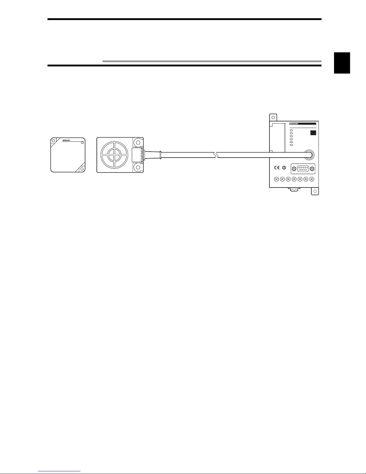
♦ ID Controller (referred to as “Controller”)
• Model V670-CD1D-V1
Model V670-CD1D-V1 connects to a personal computer (referred to as "PC") and/or programmable controller (PLC) and controls
the RFID system.
Model V670-CD1D-V1 has a general-purpose I/O terminal and a function to judge and process independently (Self-Execution
mode) and, therefore, a very fast system can be configured for simple process only without any host device.
♦ Antenna (referred to as “Antenna”)
• Model V670-H11
Model V670-H11 is a waterproof antenna (standard antenna) with dimensions of 4 × 5.3 cm. Model V670-H11 can achieve the communication range of 20 mm in combination with model V670-D13F03. Model V670-H11 has a very fast communication performance and can transfer 12 bytes of data in approximately 5 ms.
• Model V670-H51
Model V670-H51 is a cylindrically-shaped waterproof antenna. Model V670-H51 can achieve a communication range of 5.0 mm
when combined with Model V670-D13F01 or V670-D13F01H tag. Model V670-H51 has a communication performance as high as
that of Model V670-H11.
• Model V670-H51Q
Model V670-H51Q is a cylindrically-shaped antenna. Housed in a Teflon (tetrafluoroethylene) casing, Model V670-H51Q is highly
resistant to chemicals. Model V670-H51Q can achieve a communication range of 4.5 mm when combined with Model V670D13F01 or V670-D13F01H tag. Model V670-H51Q has a communication performance as high as that of Model V670-H11.
V6 70-CD1 D
V670-CD1D-V1
ID
V670-D13F03
ID
Model V670-D13F03
Model V670-H11
Model V670-CD1D-V1
Chapter 1 Features and System Configuration
1-1 Features

1-1 Features
1-2
♦ ID tag (referred to as “Tag”)
• Model V670-D13F03
Model V670-D13F03 is a waterproof tag which has 128 bytes of memory capacity with dimensions of 40 × 40 mm. Model V670D13F03 uses high-performance nonvolatile memory called Ferroelectric RAM (FeRAM) as internal memory. So, memory life is
semi-permanent. (The memory can be accessed one billion times.)
• Model V670-D13F01
Model V670-D13F01 is a rectangular tag with dimensions of 8 mm × 16 mm. Model V670-D13F01 is highly resistant to chemicals
since it is housed in a PPS casing filled with chemical-resistant epoxy resin. Model V670-D13F01 has the same memory capacity
and characteristics as those of Model V670-D13F03.
• Model V670-D13F01H
Model V670-D13F01H is a tag provided with screw holes to assure the same performance and construction as those of Model V670D13F01, and is easy to install.
• Model V670-A81
Model V670-A81 is an attachment specially designed for Model V670-D13F01H. When combined with Model V670-A81, Model
V670-D13F01H retains its original communication range even when fitted to a steel structure. Made of PPS, Model V670-A81 is
highly resistant to chemicals.
♦ Easy to use
By connecting the programming console model C200H-PRO27 (unbundled, referred to as "ProCon") to the Controller via the special
cable model V700-P10 (unbundled), the system operation status and error log information can be read. This is useful for system startup and maintenance at a working site.
Ferroelectric RAM (FeRAM)
Ferroelectric RAM is one of nonvolatile RAMs and data can be written into and read from it faster than conventional memory (such
as EEPROM and flash ROM). Data can be written into the ferroelectric RAM semi-permanently.
While any conventional RAM cannot hold data if nothing is written into it for a specified period (approximately 10 years), the ferroelectric RAM can hold data if anything is written into or read from it. So, the characteristic of ferroelectric RAM is very excellent in
data-holding performance.
Precaution for Correct use
In consequence of diversification of small-size antennas/tags, the ID controller has been upgraded to Model V670-CD1D-V1. Be
sure to combine Model V670-H51 or Model V670-H51Q antenna with Model V670-CD1D-V1 controller. Combination of this
antenna with Model V670-CD1D controller might result in unstable communication.
1-3
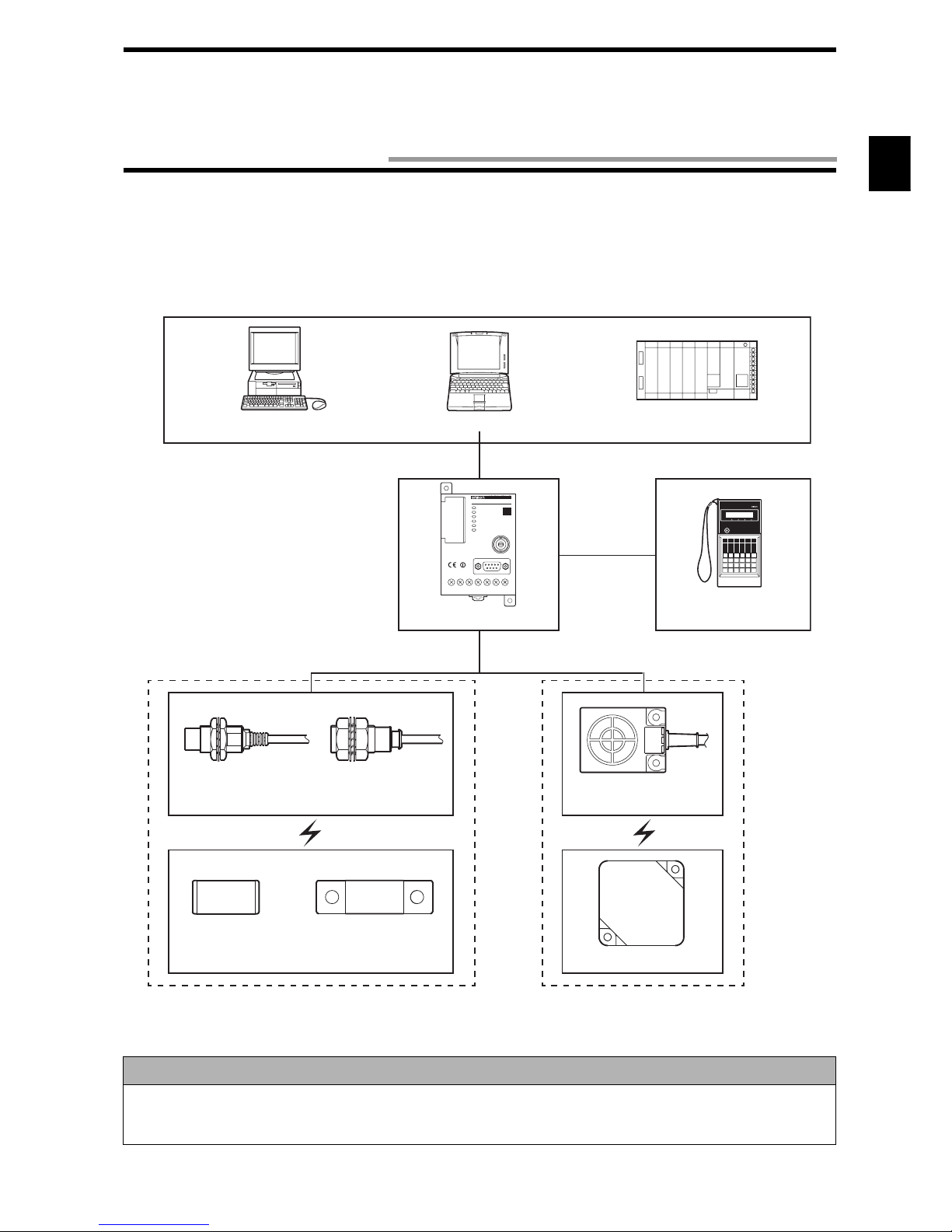
• Example of Model V670-CD1D-V1 system configuration
Model V670-CD1D-V1 contains a serial interface based on RS-232C and can connect easily to a general-purpose PC and programmable controller (PLC). Model V670-CD1D-V1 has a command execution mode and self-execution mode as an operation mode and
controls the communication to a tag according to the instructions from a host device (in the command execution mode) or the registered conditions (in the self-execution mode).
<Host Devices>
Precaution for Correct use
In consequence of diversification of small-size antennas/tags, the ID controller has been upgraded to Model V670-CD1D-V1. Be
sure to combine Model V670-H51 or Model V670-H51Q antenna with Model V670-CD1D-V1 controller. Combination of this
antenna with Model V670-CD1D controller might result in unstable communication.
PRO27
V6 70-CD1 D
V670-CD1D-V1
ID
Desktop PC
Notebook PC
Programmable Controller
(PLC)
Model V670-CD1D-V1
Model V700-P10
Model C200H-PRO27
Model V670-A4
F
(Only when extension cable is used)
Model V670-H11
Model V670-D13F03
Model V670-H51
Model V670-H51Q
Model V670-D13F01 Model V670-D13F01H
1-2 System Configuration

1-4
2-1
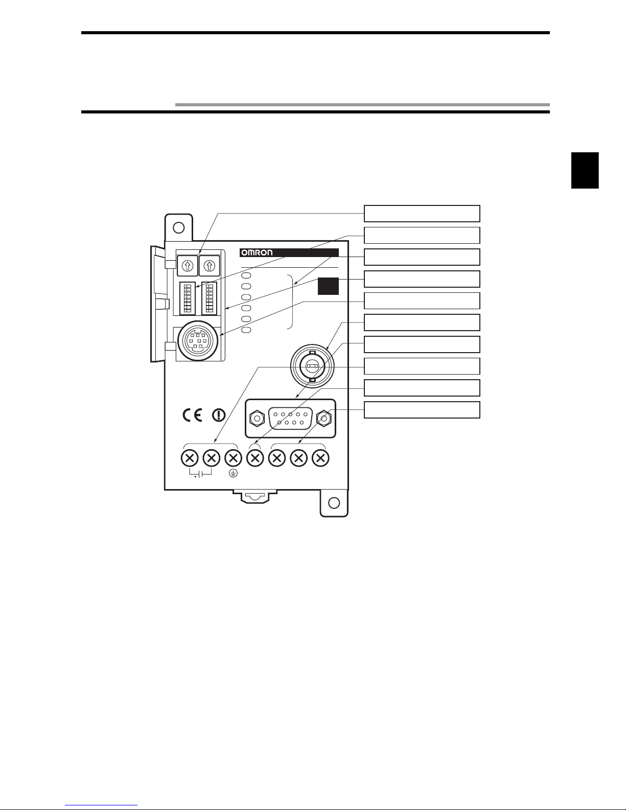
2-1-1 Component Names and Functions
• Model V670-CD1D-V1
0
1
2
3
4
5
6
7
8
9
0
1
2
3
4
5
6
7
8
9
SW1 SW2
SW3
SW4
RUN
COMM
NORM/ERR
RST/IN
OUT1
OUT2
ANTENNA
RS-232C
O.COMOUT2
GR
RST
/IN
OUT1
MADE IN JAPAN
24VDC
24VDC 7W
V6 7 0 - CD 1 D
V670-CD1D-V1
ID
(1)Node number setup switch
(2)Dip switch
(3)LED display
(4)Cover
(5)Connecting port for
programming console
(6)Connecting port for antenna
(7)RS-232C port
(8)Power supply terminals
(9)Reset terminal/Input terminal
(10)Output terminals
Chapter 2 Specifications and Performance
2-1 Controller
2-1 Controller
2-2
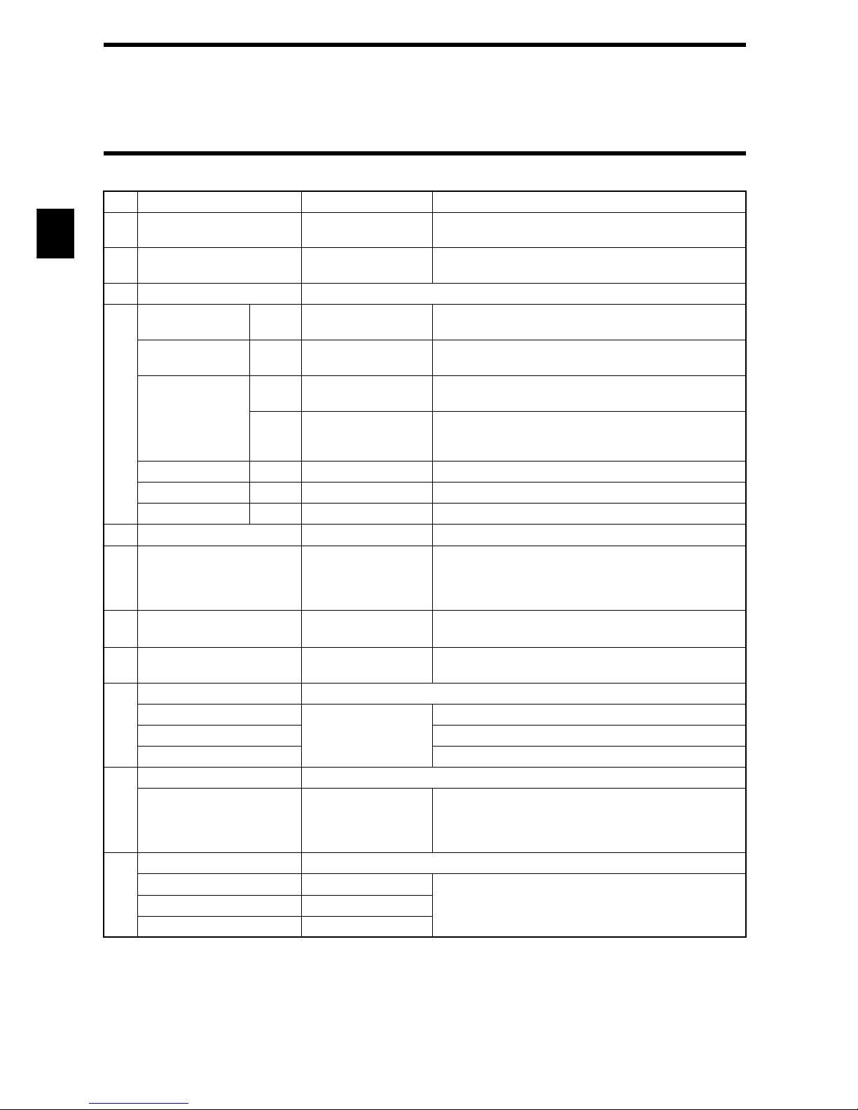
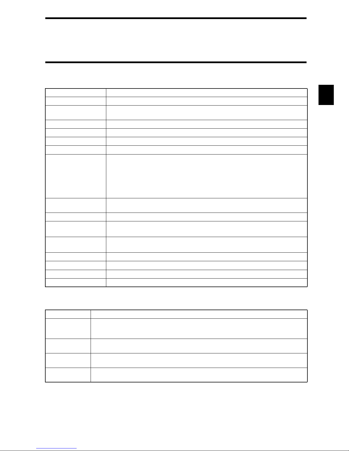
No.
Name Function Description
(1) Note number setup switch Sets a controller node
number.
Used to identify the controllers when a maximum of 31
controllers are connected to one host computer.
(2) Dip switch Sets every mode. Sets an input function, operation mode, protocol, com-
munication conditions, etc.
(3) LED display An operation status is shown on this LED displayed.
RUN Green Shows the RUN sta-
tus.
Turns on when an operation is normal.
COMM Green Shows an operation
status.
Turns on during the communication to a tag.
NORM/ERR Green Shows the end of
communication.
Turns on once and turns off when the communication has
ended correctly.
Red Shows an error. Turns on once and turns off when the communication has
ended due to an error. Turns on when a system error
occurs.
RST/IN Green
Shows an input status.
Turns on when the RST/IN input signal turns ON.
OUT1 Green
Shows an output status.
Turns on when the OUT1 output signal turns ON.
OUT2 Green
Shows an output status.
Turns on when the OUT2 output signal turns ON.
(4) Cover
Cover common to (1), (2) and (5).
Open as necessary.
(5) Connecting port for pro-
gramming console
Used to connect a
programming console.
Our programming console type C200H-PRO27 (unbundled)
can connect to this port through the connecting cable model
V700-P10 (unbundled). When you operate the programming
console, use the key sheet that comes with the V700-P10.
(6) Connecting port for antenna Used to connect an
antenna.
One antenna can connect to this port. To extend the
cable, use model V670-A4
(unbundled).
(7) RS-232C port Used to connect a
host device.
Based on the RS-232C, a general-purpose programmable controller (PLC) and PC can connect to this port.
(8) Power supply terminal Terminal for power supply.
24 VDC+ Supplies the power. Connects the "+" side of 24 VDC power supply.
24 VDC- Connects 0 V.
GR Ground Class D (Class III).
(9) Input terminal Terminal for input.
RST/IN Supplies a reset sig-
nal or trigger signal.
When external reset input and external trigger input are
used, they connects to this terminal together with 24
VDC- in pairs. Function can be selected with a dip
switch.
(10)
Output terminal Terminal for output.
OUT1 Output signal 1 When external output is used, it connects to this terminal
together with O.COM in pairs.
OUT2 Output signal 2
O.COM Output common
2-1 Controller
2-3
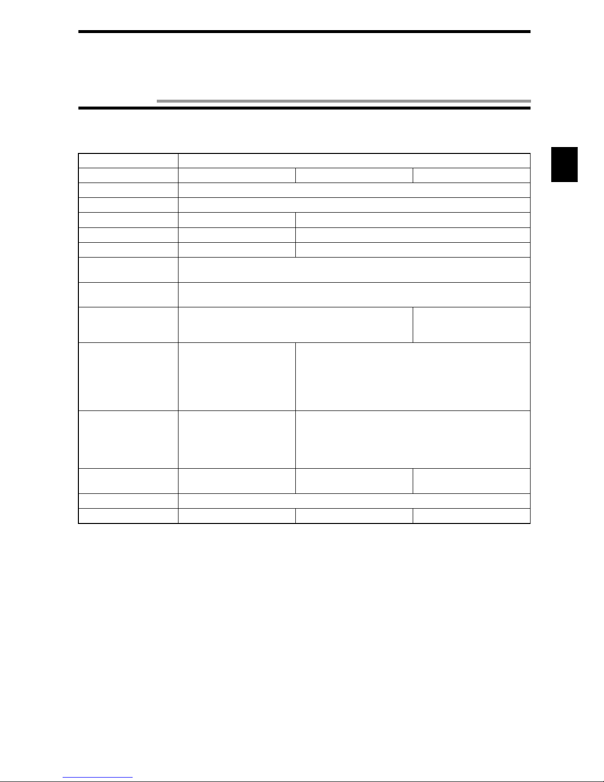
2-1-2 General Specifications
2-1-3 Performance Specifications
Item Specifications
Model V670-CD1D-V1
Power supply voltage
(Power consumption)
24 VDC±10%
(7 W or less)
Ambient operating temperature
0 to +55°C (no icing)
Ambient operating humidity
35 to 85%RH (no condensation)
Ambient storage temperature
-20 to +75°C (no icing)
Ambient storage humidity 35 to 85%RH (no condensation)
Insulation resistance 20 MΩ or more (at 1,000 VDC mega) (1) to (6).
(1) Between a group of the power supply terminals and the grounding terminal.
(2) Between a group of the power supply terminals and a group of the output terminals.
(3) Between a group of the power supply terminals and the case.
(4) Between a group of the output terminals and the grounding terminal.
(5) Between a group of the output terminals and the case.
(6) Between the grounding terminal and the case.
Withstand voltage Leakage current 5 mA or less at 1,000 VAC (for 1 minute).
Impressed to (1) to (6) above.
Protective structure Contains a panel.
Vibration resistance
10 to 150 Hz, double amplitude 0.2 mm, acceleration 15 m/s
2
.
Performing sweep 10 times for 8 minutes in an upward, downward, leftward, rightward, forward and backward directions.
Impact
Giving impact of 150 m/s
2
3 times each in upward, downward, leftward, rightward, forward
and backward directions, i.e., 18 times in total.
Ground According to Class D (conventional Class III)
Material PC/ASA resin
Weight Approximately 270 g
Installation DIN or M4 screws
Item Specifications
Communication
function
Single/Repeat/Input mode access function.
Write protect function/Memory check function
Self-Execution Function
Maintenance
function
Error reading function
Diagnosis function
CPU error, host communication error, satellite communication error.
I/O function Input contact: 1 (RST/IN)
Output contact: 2 (OUT1 and OUT2)
2-1 Controller
2-4
2-1-4 Communication Specifications
* This can be set by a dip switch of the controller. For how to set, refer to Chapter 3.
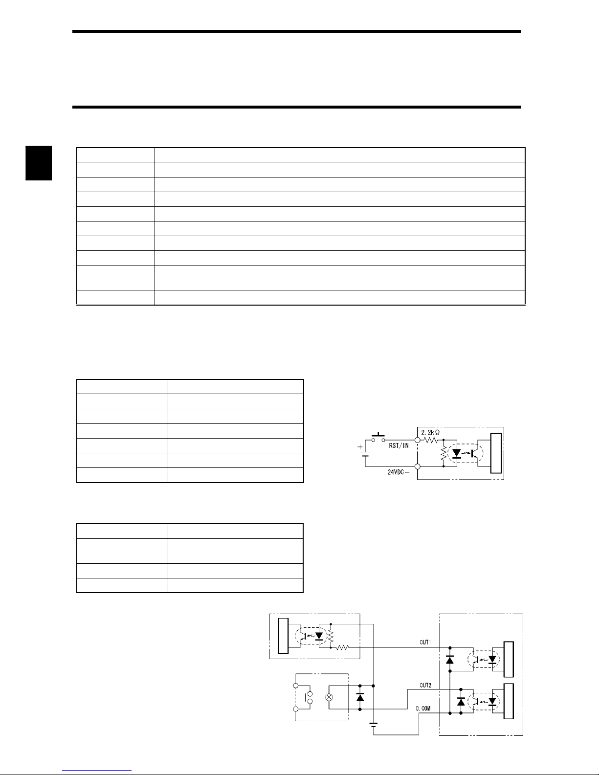
2-1-5 I/O Specifications
• Input Specifications (RST/IN)
• Output Specifications (OUT1/OUT2)
The output is the open collector specification.
Item Specifications
Base specification RS-232C
Communication method
EIA/TIA-232-E
Transmission rate 9600 bps, 19200 bps, 38400 bps, 115200 bps *
Synchronization method
Start-stop synchronization (Stop bit 1 or 2) *
Transmission code
ASCII7 unit or JIS8 unit *
Error control Vertical parity (even, odd, nil)*. Horizontal parity is used as FCS.
Line length A maximum of 15 m.
Suitable connector
D-SUB 9-pin, male
Model XM2A-0901 (plug) and model XM2S-0911 (hood), which come with our controller.
Recommendable cable
CO-MA-VV-SB 5Px28AWG (Hitachi Cable)
Item Specifications
Input voltage 24 VDC ±10% (including ripple)
Input impedance 2.2 kΩ
Input current 10 mA TYP (24 VDC)
ON voltage 19 to 24 V
OFF voltage 5 V or less
Input response time 40 µs or less
Item Specifications
Maximum open/close
ability
24 V ±10% 100 mA
Leakage current 1 µA or less
Residual voltage 1.0 V or less
Internal circuit
24VDC
Circuit Structure
Controller input section
Circuit Structure
Input circuit Controller output section
Relay
Internal circuit
InternalInternal
24VDC
2-1 Controller
2-5
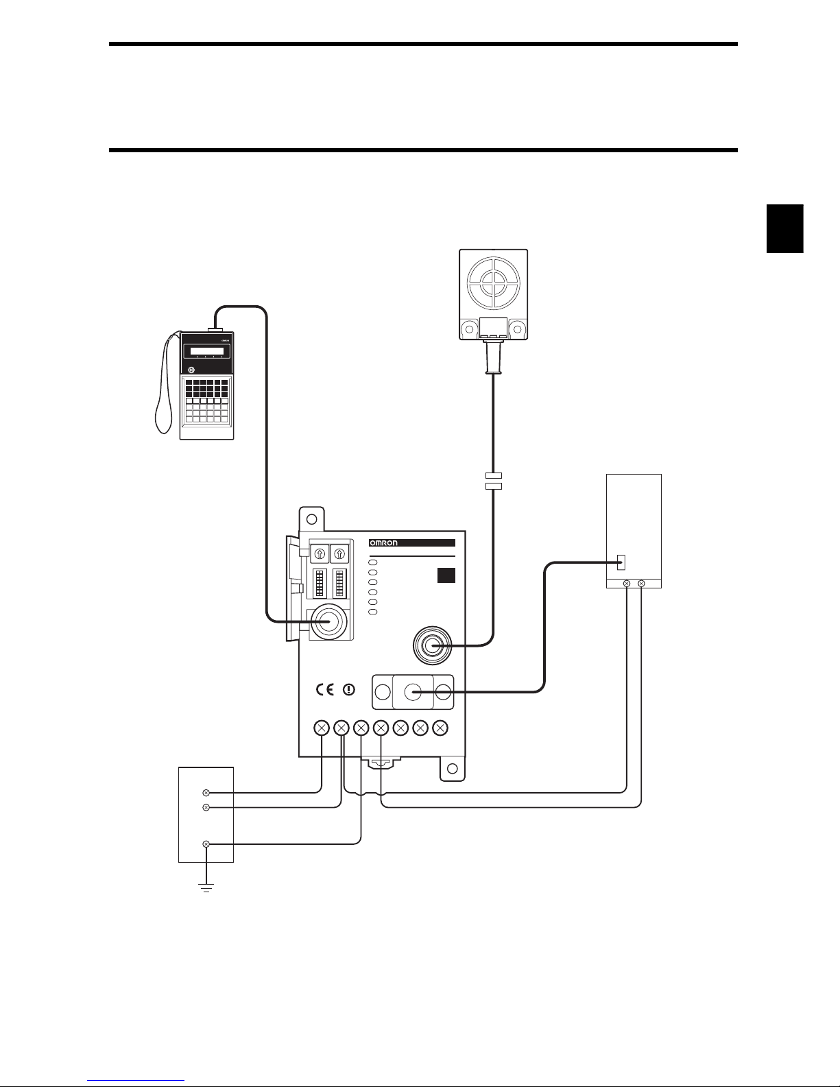
2-1-6 Example of Wiring
0
1
2
3
4
5
6
7
8
9
0
1
2
3
4
5
6
7
8
9
SW1 SW2
SW3
SW4
ANTENNA
RS-232C
COMRST
GR
+
SYNC
–
MADE IN JAPAN
24VDC
PRO27
COM24VDC+
24VDC-
GR
RS-232C
RESET
RUN
COMM
NORM/ERR
RST/IN
OUT1
OUT2
V670-CD1D-V1
ID
Connecting Cable
Model V700-P10
Controller
Model V670-CD1D-V1
Antenna Type
Model V670-H11
Host Programmable
Controller (PLC)
Antenna Cable
Model V670-A4
(Only when extension
cable is used)
Programming Console
Model C200H-PRO27
24 VDC Power Supply
2-1 Controller
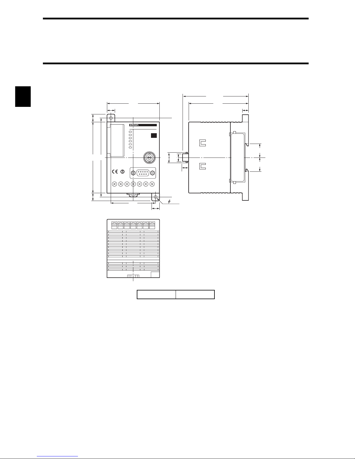
2-6
2-1-7 Outside Dimension
Case material PC/ASA resin
10 8
10
10
10
5.5
100
66
56
75
Max. 85
17.5
18
90
2- 4.5
11.5 9.5
V6 70-CD1 D
V670-CD1D-V1
ID
(Unit: mm)
2-7
2-2-1 Specifications
*1: Connectors are not waterproof.
*2: Teflon is the registered trade name of fluorocarbon resin made by DuPont Company and Mitsui DuPont Fluorochemical
Co., Ltd.
Item Specifications
Model V670-H11 V670-H51 V670-H51Q
Oscillating frequency 13.56 MHz
Ambient operating temperature
-10 to +70°C
Ambient operating humidity
35 to 85%RH 35 to 95%RH
Ambient storage temperature
-25 to +85°C -25 to +75°C
Ambient storage humidity
35 to 85%RH 35 to 95%RH
Insulation resistance 20 MΩ or more (at 1,000 VDC mega).
Impressed between a group of terminals and a case.
Withstand voltage 1,000 VAC (for 1 minute).
Impressed between a group of terminals and a case. Leakage current 1 mA or less.
Protective structure IP67 (IEC60529 Standard) *1
IP67 (IEC60529 Standard) *1
IP67g (for communication
side only, JEM Standard)
Vibration resistance
10 to 150 Hz, double amplitude
0.7 mm, acceleration 50 m/s
2
.
Performing sweep 10 times for 8 min-
utes in an upward, downward, left-
ward, rightward, forward and
backward directions.
10 to 500 Hz, double amplitude 1.5 mm, acceleration 100 m/s2.
Performing sweep 10 times for 11 minutes in an upward, down-
ward, leftward, rightward, forward and backward directions.
Impact
Giving impact of 150 m/s
2
3
times each in upward, down-
ward, leftward, rightward,
forward and backward direc-
tions, i.e., 18 times in total.
Giving impact of 300 m/s2 3 times each in upward, down-
ward, leftward, rightward, forward and backward directions,
i.e., 18 times in total.
Material
ABS/epoxy filler
(Cable section material is PVC.)
PBT/brass/filled with epoxy
resin
Teflon*2/filled with epoxy
resin
Cable length 2 m
Weight Approximately 160 g Approximately 140 g Approximately 130 g
2-2 Antenna
2-2 Antenna
2-8
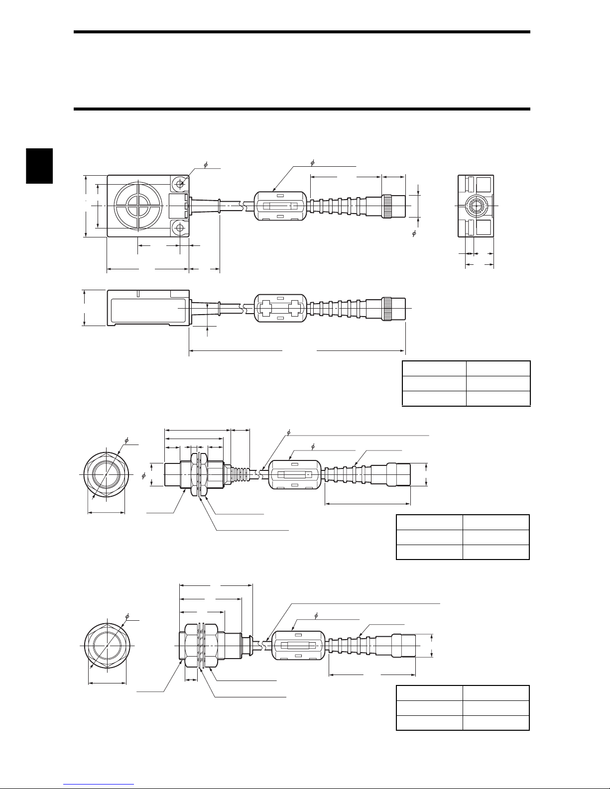
2-2-2 Outside Dimension
• Model V670-H11
• Model V670-H51
• Model V670-H51Q
Case material ABS resin
Filler resin Epoxy resin
Cable PVC
44.9
2- 4.5
Core 18
× 34 mm
15.4
15
11
23
40
20
6
53
2000
27
18
5
13
28 ±
0.1
+70
-0
(Unit: mm)
29
14.8
10
38
43 12
5.0 coaxial cable with a standard length of 2 m
Connector
60.3
15
410
M18 × 1
2-stuffing nut
Toothed lock washer
2
4
Core 18 × 34 mm
(Unit: mm)
Case material Brass/PBT
Filler resin Epoxy resin
Cable PVC
Toothed lock washer
2-stuffing nut
29
47
40
29
8
M18 × 1
24
5.0 coaxial cable with a standard length of 2 m
Connector
60.3
1
5
Core 18 × 34 mm
(Unit: mm)
Case material Teflon
Filler resin Epoxy resin
Cable PVC
2-9
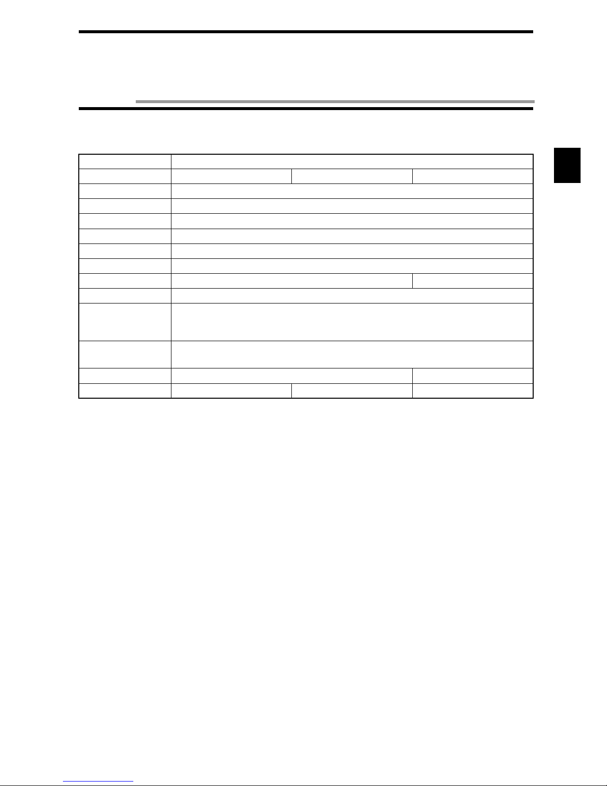
2-3-1 Specifications
* Number of accesses is the total number of read/write communication times.
Item Specifications
Model V670-D13F01 V670-D13F01H V670-D13F03
Memory capacity 128 bytes
Type of memory FeRAM (Ferroelectric RAM)
Memory life Number of accesses*: One billion
Data-holding period 10 years after accessing (read or write).
Ambient operating temperature
-10 to +70°C
Ambient storage temperature
-10 to +70°C
Ambient operating humidity
35 to 95%RH 35 to 85%RH
Protective structure IP67 (IEC60529 Standard)
Vibration
10 to 2000 Hz, double amplitude 1.5 mm, acceleration 150 m/s2.
Performing sweep 10 times for 15 minutes in an upward, downward, leftward, rightward, for-
ward and backward directions.
Impact
Giving impact of 500m/s
2
3 times each in upward, downward, leftward, rightward, forward and
backward directions, i.e., 18 times in total.
Material PPS/epoxy filler resin ABS/epoxy filler resin
Weight Approximately 1 g Approximately 1 g Approximately 6 g
2-3 Tag
2-3 Tag
2-10
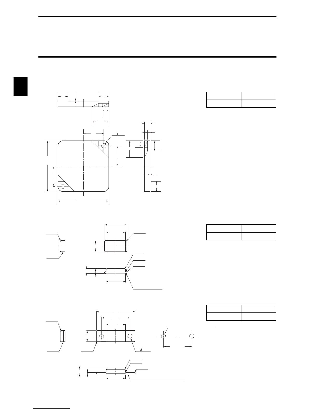
2-3-2 Outside Dimension
• Model V670-D13F03
• Model V670-D13F01
• Model V670-D13F01H
16
2-
3.5
16
40+ 0.1
- 0.5
16
40+ 0.1
-
0.5
16
5.2
8
13.2
0.2
8
13.2
4.5
2
0.2
5.2
8
Case material ABS resin
Filler resin Epoxy resin
(Unit: mm)
Reference plane
for installation
8
3.5
1.2
14
2-R0.8
2-R0.2
2-R0.2
14
16
4-R0.5
2-R0.8
2-R0.2
Case material PPS resin
Filler resin Epoxy resin
(Unit: mm)
2-R0.8
2-R0.2
8
14
20.5
28
4-R0.5
2-R0.8
2-R0.2
2-R0.2
3.5
1.2
14
2- 3.2
20.5 ±
.1
Reference hole for installation
2- 3.2 hole for M3 screw
Reference plane for installation
Fitting hole dimension
φ
Case material PPS resin
Filler resin Epoxy resin
(Unit: mm)
2-3 Tag
2-11
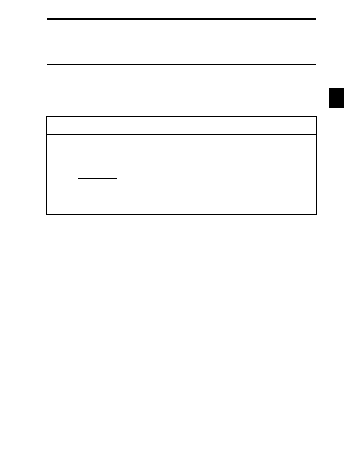
2-3-3 Memory Map
There are a user area and ID code in memory in a tag. Memory capacity of user area is 128 bytes. You can write 1 byte of data into one
address. Memory area is divided into 4 bytes of pages and every page has its own address like 0000h to 0003h, 0004h to 0007, etc.
♦ Memory Map
* When a protect function is used, the addresses 0000h to 0003h are used as protect address information and cannot be used as a user
area. For details, refer to "4-6 Write Protection Function".
♦ ID Code
This is a 4-byte area where tag identification number (inherent tag number) is written. The ID code is written at shipment from a factory and it cannot be modified. The ID code can be read by an ID read command.
Page User Address
User Area
When a protect function is not used When a protect function is used
1
$0000
User Area
Specified address in a protect area
$0001
$0002
$0003
.
.
.
.
$0004
User Area
.
.
.
.
$007F
2-3 Tag
2-12
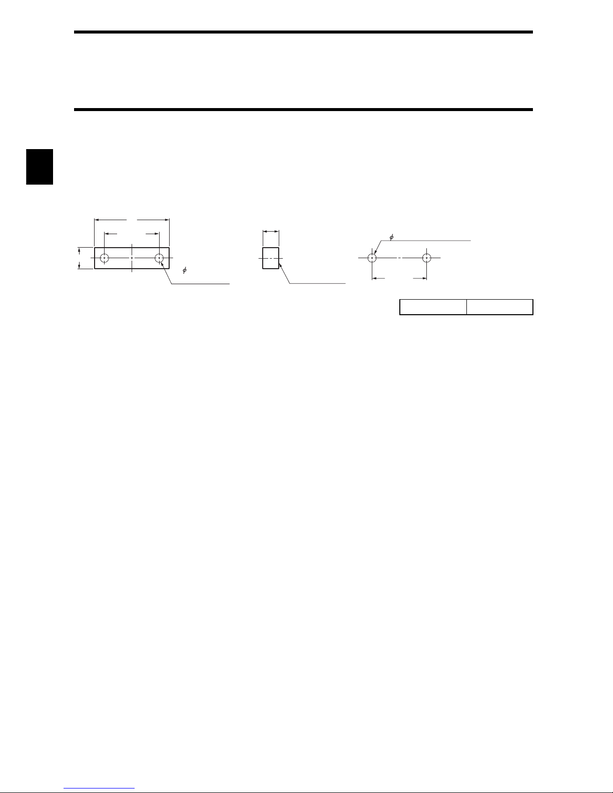
2-3-4 Attachment (Model V670-A81) for Model V670-D13F01H Tag
When a tag is attached to a metal structure, the metal will reduce the communication range of the tag. Model V670-A81 is an attachment
specially designed for Model V670-D13F01H Tag. When combined with this attachment, Model V670-D13F01H tag retains its original
communication range even when installed on a metal structure.
Tag to be combined: Model V670-D13F01H
♦ Outside Dimension
♦ How to install
Place the attachment on the reference plane of the tag and adjust its position until the fitting holes align with each other. Then secure
both parts with M3 screws.
Screw tightening torque: 5 N • m
♦ For general applications
Conform to the tag specifications.
♦ Influence of back metal
Use of this attachment increases the distance between the tag and metal surface to 6 mm. Before use, refer to Chapter 9-4, "Influence
of Back Metal of Tag."
Material PPS resin
20.5
± 0.1
2- 3.2 hole for
M3 screw
8
6
Reference plane
for installation
28
20.5
± 0.1
Reference hole for installation
Fitting hole dimension
2- 3.2 hole for M3 screw
2-13
2-4-1 Specifications
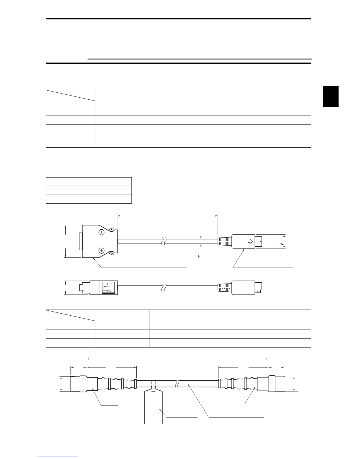
2-4-2 Outside Dimension
• Model V700-P10 (Programming console connecting cable)
• Model V670-A4 (Antenna extension cable)
Model V700-P10 Model V670-A4
Insulation resistance
50 MΩ or more between a terminal and
sheathing (at 250 VDC mega).
20 MΩ or more between a terminal and
sheathing (at 1000 VDC mega).
Withstand voltage 250 VAC, 1 minute. 1000 VAC, 1 minute.
Maximum operating
temperature
70°C70°C
Remarks Connector without waterproof specification. Connector without waterproof specification.
Item Model V700-P10
Length Approximately 2 m
Weight Approximately 110 g
Model V670-A40 Model V670-A41 Model V670-A42 Model V670-A43
Length Approximately 3 m
Approximately 10 m Approximately 18 m Approximately 28 m
Weight
Approximately 140 g Approximately 410 g Approximately 710 g
Approximately 1100 g
L1 3000 mm 10000 mm 18000 mm 28000 mm
Model
Item
12
4.8
2000±
100
28.95
Connector (at a programming console side)
Connector (at a controller)
12
(Unit: mm)
Model
Item
44.9
L1
44.9
Connector
Connection label
Coaxial cable 5 mm in diameter
Connector
15
15
15.4 15.4
+50
-0
(Unit: mm)
2-4 Cable
2-14
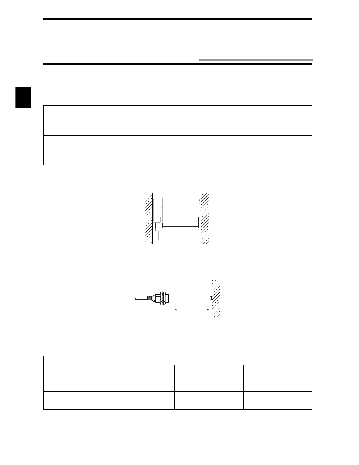
Communication range varies depending on the installation conditions and environment conditions. Check the conditions mentioned in
this manual carefully.
♦ Maximum communication range
Measurement conditions:
• Combination of Model V670-H11 with Model V670-D13F03
*Antenna extension cable (Model V670-A4: not used)
• Combination of Model V670-H51/H51Q with Model V670-D13F01/D13F01H
*Antenna extension cable (Model V670-A4: not used)
♦ Use of extension cable (Model V670-A4)
Use of an extension cable will reduce the communication range.
* For extension cable connection procedure, refer to the descriptions on pages 3-9 and the instruction manual packaged together with
the extension cable.
Antenna / Controller ID Tag Communication Range
Model V670-H11
+ Model V670-CD1D-V1
Model V670-D13F03 5 to 23 mm
(Area width 20 mm or more if the range between a tag
and antenna is 5 to 20 mm.)
Model V670-H51
+ Model V670-CD1D-V1
Model V670-D13F01 /
Model V670-D13F01H
0.5 to 5.0 mm
Model V670-H51Q
+ Model V670-CD1D-V1
Model V670-D13F01 /
Model V670-D13F01H
0.5 to 4.5 mm
Extension cable
Communication range
Model V670-H11 Model V670-H51 Model V670-H51Q
Model V670-A40 (3 m) 5.0 to 21.5 mm 0.5 to 5.0 mm 0.5 to 4.5 mm
Model V670-A41 (10 m) 5.0 to 21.0 mm 0.5 to 5.0 mm 0.5 to 4.5 mm
Model V670-A42 (18 m) 5.0 to 20.5 mm 0.5 to 4.0 mm 0.5 to 3.5 mm
Model V670-A43 (28 m) 5.0 to 20.0 mm 0.5 to 4.0 mm 0.5 to 3.5 mm
Antenna
Nonmetal Nonmetal
Ta g
Communication
range
Antenna
Nonmetal
Ta g
Communication
range
2-5 Communication Range Specifications
 Loading...