

Page 1

Cat. No.Z219-E1-02
V600 Series
RFID System
USER´S MANUAL
Page 2

Page 3

Introduction
ÇÕǹÇ?Ç ëÊ 1 èÕ ëÊ 2 èÕ ëÊ 3 èÕ ëÊ 4 èÕ
Introduction
Section 1
Section 2
Section 3
Section 4
Section 5
Application Considerations (Read and understand this information first.)
Section 1 Section 2 Section 3 Section 4 Section 5 Section 6
Product Overview
Communications Preparations
Commands
Functions
Troubleshooting
Section 6
Appendices
RFID System
V600-CHUD Hand-held Reader Writer
V600-CH1D-V2 Hand-held Reader Writer
V600 Series Data Carriers
User’s Manual
Page 4

Introduction
Introduction
EAD AND UNDERSTAND THIS DOCUMENT
R
Please read and understand this document before using the products. Please consult your OMRON representative if you have any questions or comments.
WARRANTY
OMRON’s exclusive warranty is that the products are free from defects in materials and workmanship for a period of one year (or other period if specified)
from date of sale by OMRON.
OMRON MAKES NO WARRANTY OR REPRESENTATION, EXPRESS OR IMPLIED, REGARDING NON-INFRINGEMENT, MERCHANTABILITY, OR
FITNESS FOR PARTICULAR PURPOSE OF THE PRODUCTS. ANY BUYER OR USER ACKNOWLEDGES THAT THE BUYER OR USER ALONE HAS
DETERMINED THAT THE PRODUCTS WILL SUITABLY MEET THE REQUIREMENTS OF THEIR INTENDED USE. OMRON DISCLAIMS ALL OTHER
WARRANTIES, EXPRESS OR IMPLIED.
LIMITATIONS OF LIABILITY
OMRON SHALL NOT BE RESPONSIBLE FOR SPECIAL, INDIRECT, OR CONSEQUENTIAL DAMAGES, LOSS OF PROFITS OR COMMERCIAL LOSS IN
ANY WAY CONNECTED WITH THE PRODUCTS, WHETHER SUCH CLAIM IS BASED ON CONTRACT, WARRANTY, NEGLIGENCE, OR STRICT
LIABILITY.
In no event shall responsibility of OMRON for any act exceed the individual price of the product on which liability is asserted.
IN NO EVENT SHALL OMRON BE RESPONSIBLE FOR WARRANTY, REPAIR, OR OTHER CLAIMS REGARDING THE PRODUCTS UNLESS OMRON’S
ANALYSIS CONFIRMS THAT THE PRODUCTS WERE PROPERLY HANDLED, STORED, INSTALLED, AND MAINTAINED AND NOT SUBJECT TO
CONTAMINATION, ABUSE, MISUSE, OR INAPPROPRIATE MODIFICATION OR REPAIR.
SUITABILITY FOR USE
THE PRODUCTS CONTAINED IN THIS DOCUMENT ARE NOT SAFETY RATED. THEY ARE NOT DESIGNED OR RATED FOR ENSURING SAFETY OF
PERSONS, AND SHOULD NOT BE RELIED UPON AS A SAFETY COMPONENT OR PROTECTIVE DEVICE FOR SUCH PURPOSES. Please refer to
separate catalogs for OMRON's safety rated products.
OMRON shall not be responsible for conformity with any standards, codes, or regulations that apply to the combination of products in the customer’s
application or use of the product.
At the customer’s request, OMRON will provide applicable third party certification documents identifying ratings and limitations of use that apply to the
products. This information by itself is not sufficient for a complete determination of the suitability of the products in combination with the end product,
machine, system, or other application or use.
The following are some examples of applications for which particular attention must be given. This is not intended to be an exhaustive list of all possible uses
of the products, nor is it intended to imply that the uses listed may be suitable for the products:
• Outdoor use, uses involving potential chemical contamination or electrical interference, or conditions or uses not described in this document.
• Nuclear energy control systems, combustion systems, railroad systems, aviation systems, medical equipment, amusement machines, vehicles, safety
equipment, and installations subject to separate industry or government regulations.
• Systems, machines, and equipment that could present a risk to life or property.
Please know and observe all prohibitions of use applicable to the products.
NEVER USE THE PRODUCTS FOR AN APPLICATION INVOLVING SERIOUS RISK TO LIFE OR PROPERTY WITHOUT ENSURING THAT THE SYSTEM
AS A WHOLE HAS BEEN DESIGNED TO ADDRESS THE RISKS, AND THAT THE OMRON PRODUCT IS PROPERLY RATED AND INSTALLED FOR THE
INTENDED USE WITHIN THE OVERALL EQUIPMENT OR SYSTEM.
PERFORMANCE DATA
Performance data given in this document is provided as a guide for the user in determining suitability and does not constitute a warranty. It may represent the
result of OMRON’s test conditions, and the users must correlate it to actual application requirements. Actual performance is subject to the OMRON Warranty
and Limitations of Liability.
CHANGE IN SPECIFICATIONS
Product specifications and accessories may be changed at any time based on improvements and other reasons.
It is our practice to change model numbers when published ratings or features are changed, or when significant construction changes are made. However,
some specifications of the product may be changed without any notice. When in doubt, special model numbers may be assigned to fix or establish key
specifications for your application on your request. Please consult with your OMRON representative at any time to confirm actual specifications of purchased
products.
DIMENSIONS AND WEIGHTS
Dimensions and weights are nominal and are not to be used for manufacturing purposes, even when tolerances are shown.
ERRORS AND OMISSIONS
The information in this document has been carefully checked and is believed to be accurate; however, no responsibility is assumed for clerical, typographical,
or proofreading errors, or omissions.
PROGRAMMABLE PRODUCTS
OMRON shall not be responsible for the user’s programming of a programmable product, or any consequence thereof.
COPYRIGHT AND COPY PERMISSION
This document shall not be copied for sales or promotions without permission. This document is protected by copyright and is intended solely for use in
conjunction with the product. Please notify us before copying or reproducing this document in any manner, for any other purpose. If copying or transmitting
this document to another, please copy or transmit it in its entirety.
RFID System
2
User's Manual
Page 5
Meanings of Signal Words
Introduction
Introduction
The following signal words are used in this manual.
Indicates a potentially hazardous situation which, if not avoided, will result in minor or moderate
WARNING
CAUTION
injury, or may result in serious injury or death. Additionally, there may be significant property
damage.
Indicates a potentially hazardous situation which, if not avoided, may result in minor or moderate
injury or in property damage.
Meanings of Alert Symbols
The following alert symbols are used in this manual.
Indicates the possibility of explosion under specific conditions.
Indicates general prohibitions for which there is no specified symbol.
Meanings of Signal Words
Alert Statements in This Manual
The following alert statements apply to the products in this manual. Each alert statement also appears at the locations
needed in this manual to attract your attention.
WARNING
This product is not designed to be used either directly or indirectly in applications that detect
human presence for the purpose of maintaining safety. Do not use this product as a sensing device
for protecting human lives.
A lithium battery is built into SRAM Data Carriers and may occasionally combust, explode, or burn
if not treated properly. Dispose of SRAM Data Carriers as industrial waste and never disassemble,
apply pressure that would deform, heat to higher than 100°C, or incinerate SRAM Data Carriers.
RFID System
User's Manual
3
Page 6
Introduction
Regulations and Standards
Introduction
Regulations and Standards
The V600-CHUD series complies with the following standards.
1. FCC (USA Federal Communications Commission)
FCC Part 15 Subpart C
FCC ID:E4E6CYCIDV6000203
2. Europe Radio and EMC Standards
The requirements of the EC/R&TTE Directive (Radio and Telecommunications Terminal Equipment Directive 1999/5/EC)
have been met.
Radio: EN300330-2 V1.1.1(06-2001) EN300300-1 V1.3.1(06-2001)
EMC: EN301489-3 V1.4.1(08-2002) EN301489-1 V1.4.1(08-2002)
Safety: EN61010-1:2001(2
ND
Edition)
Countries of intended use:
Finland, Germany, Iceland, Sweden
English Hereby, OMRON, declares that this V600-CHUD(-X) is in compliance with the essential
requirements and other relevant provisions of Directive 1999/5/EC.
Finnish Omron vakuuttaa täten että V600-CHUD(-X) tyyppinen laite on direktiivin 1999/5/EY
oleellisten vaatimusten ja sitä koskevien direktiivin muiden ehtojen mukainen.
Swedish Härmed intygar Omron att denna V600-CHUD(-X) stär l överensstämmelse med de
väsentliga egenskapskrav och övriga relevanta bestämmelser som framgår av direktiv
1999/5/EG.
German Hiermit erklärt Omron, dass sich dieser/diese/dieses V600-CHUD(-X) in Übereinstimmung
mit den grundlegenden Anforderungen und den anderen relevanten Vorschriften der
Richtlinie 1999/5/EG befindet. (BMWi)
RFID System
4
User's Manual
Page 7

Introduction
Precautions for Safe Use
Observe the following precautions to ensure safe use of the product.
1. Do not use the product in environments with flammable, explosive, or corrosive gasses.
2. Do not attempt to disassemble, repair, or modify the product.
3. The USB driver must be installed in the personal computer before connecting the V600-CHUD to a
personal computer.
4. Do not subject cables to excessive loads.
5. Observe all warnings and precautions given in the body of this manual.
6. Discontinue usage and turn OFF the power supply immediately if you notice any unusual odors, if the
product is abnormally hot, or if the product starts smoking.
7. When disposing of the product, treat it as industrial waste.
Precautions for Correct Use
Introduction
Precautions for Safe Use
Always observe the following precautions to prevent operation failures, malfunctions, and adverse effects on
performance and equipment.
1. Installation Environment
Install the product in the following locations:
• Locations not subject to corrosive gas, dust, metallic powder, or salt.
• Locations within the specified operating temperature range.
• Locations not subject to rapid changes in temperature (with no condensation).
• Locations within the specified humidity range.
• Locations not subject to direct vibration or shock outside the specified ranges.
• Locations not subject to water, oil, or chemicals.
2. Installation
• The product communicates with Data Carriers using the 530-kHz frequency band. Some motors,
inverters, switching power supplies, and other devices generate noise that can affect communications with the Data Carriers. If such devices are located near the Data Carriers, communications
with the Data Carriers may be adversely affected or the Data Carriers may be destroyed. Whenever
using the product near devices of this nature, always test operation in advance to confirm if the system will be affected.
• Observe the following precautions to minimize the effects of normal noise.
(1) Ground all metal objects in the vicinity to 100 Ω or less.
(2) Do not use the system near high-voltage or high-current lines.
• Connectors are not waterproof. Do not use the product where mists are present.
• Do not use chemicals that would affect the materials used in the product.
• Always be sure the USB connector is properly inserted when using the USB port.
3. Cleaning
• Do not clean the product with thinners, benzene, or other organic solvents. These will dissolve the
resin parts and coating on the case.
RFID System
User's Manual
5
Page 8

Introduction
How to Read this Manual
Introduction
How to Read this Manual
Meanings of Symbols
Indicates particularly important points related to a function, including precautions and application advice.
Indicates page numbers containing relevant information.
Indicates reference to helpful information and explanations for difficult terminology.
RFID System
6
User's Manual
Page 9

Introduction
Table of Contents
Introduction 2
Meanings of Signal Words 3
Meanings of Alert Symbols 3
Alert Statements in This Manual 3
Regulations and Standards 4
Precautions for Safe Use 5
Precautions for Correct Use 5
How to Read this Manual 6
Table of Contents 7
Introduction
Table of Contents
Section 1 Product Overview 9
Features 10
Names and Functions of Components 11
System Configuration 13
Operation Flowchart 15
Section 2 Communications Preparations 17
Connections 18
Installing the USB Driver (V600-CHUD) 19
V600-CH1D-V2 Communications Preparation 32
Communications Test 37
Section 3 Commands 39
Communications with the Data Carrier 40
Command and Response Format 44
Communications Commands 48
Communications Subcommands 88
Host Commands 89
Controller Control Commands 90
Other Commands 94
End code List 95
RFID System
User’s Manual
7
Page 10

Introduction
Section 4 Functions 97
Hand-held Reader Writer Functions 98
Introduction
Data Carrier 100
Section 5 Troubleshooting 111
Table of Contents
Error Tables 112
Troubleshooting Flowchart 113
Section 6 Appendices 115
Specifications and Dimensions 116
Data Carrier Memory Map 127
Data Carrier Memory Capacity and Data Type (V600 Series) 128
List of ASCII Characters 129
Degree of Protection 130
Revision History 133
RFID System
8
User’s Manual
Page 11
Section 1 Product Overview
Features 10
Names and Functions of Components 11
System Configuration 13
Operation Flowchart 15
Section 1 Product Overview
RFID System
User’s Manual
9
Page 12
Section 1
Product Overview
Features
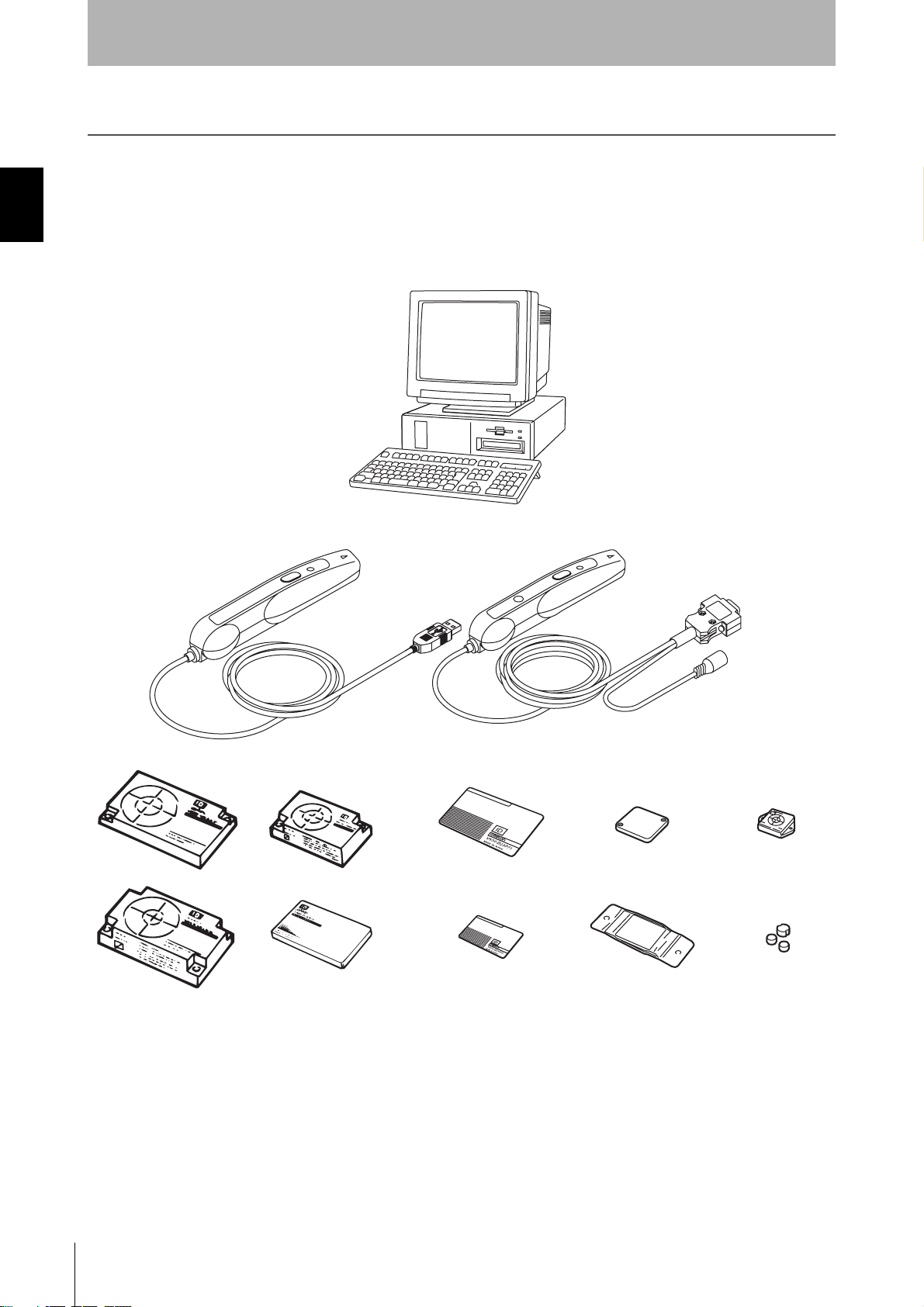
The V600-CHUD Hand-held Reader Writer incorporates a V600-series Antenna and Controller into a compact
device conforming to USB 1.1. Data can be read from or written to the Data Carrier simply by approaching or
touching the Data Carrier with the Hand-held Reader Writer.
Section 1Features
Personal computer
Hand-held Reader Writer
10
RFID System
User’s Manual
Data Carriers
Page 13
Names and Functions of Components
Section 1
Product Overview
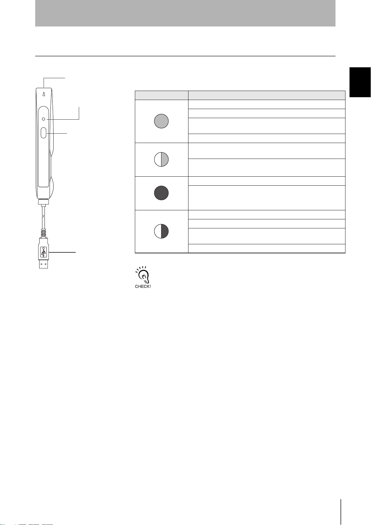
V600-CHUD
Operation indicator (LED)
Antenna
Activate switch
Interface connector
•Operation Indicator (LED)
Display Meaning
A command has been received from the host device.
Communications with the Data Carrier have completed normally.
The execution result of the noise detection command (NS) is “A” (low
Lit green
Flashing green
Lit red
Flashing red
noise).
The result of the error noise detection command (EN) is “0” (normal).
When the power is turned ON, after initialization of the Hand-held
Reader Writer is completed
Communications with the Data Carrier are in progress.
A communications error with the Data Carrier has occurred.
A CPU error has occurred.
A Data Carrier non-existent error has occurred.
A communications error with the host device has occurred.
The execution result of the noise detection command (NS) is “B” (high
noise).
The result of the error noise detection command (EN) is “1” (error).
Section 1 Names and Functions of Components
After the operation indicator is lit or flashing for a certain time, it will turn OFF.
•Activate Switch
When button commands (button commands, button auto commands) are
used and the activate switch is pressed, communications with the Data
Carrier will commence. (For details on button commands, refer to Section
3 Commands.)
•Interface Connector
This is a USB interface with an A-series plug based on USB 1.1.
•Antenna
To communicate with the Data Carrier, move the antenna head closer to
it.
RFID System
User’s Manual
11
Page 14
Section 1
Product Overview
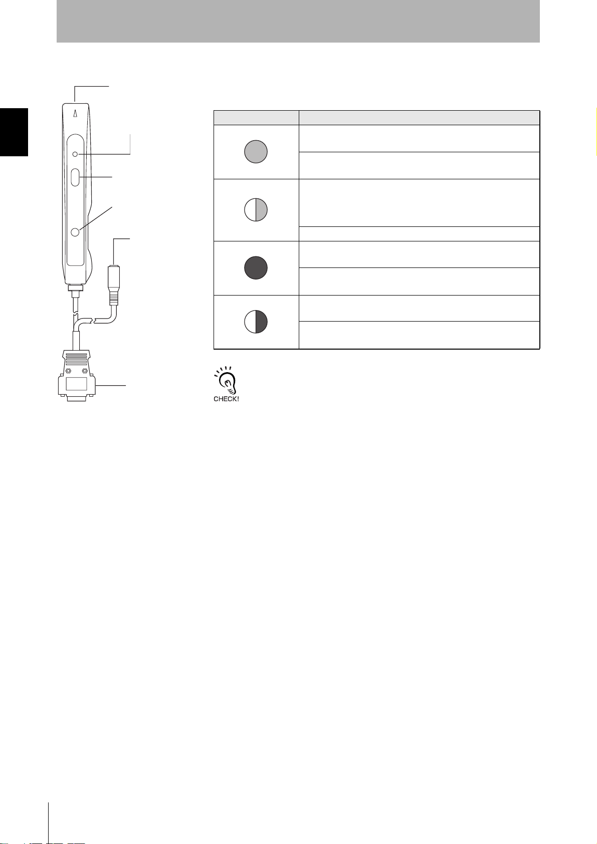
V600-CH1D-V2
Antenna
Operation indicator (LED)
•Operation Indicator (LED)
Display Meaning
A command has been received from the host device.
Section 1Names and Functions of Components
Activate switch
Reset button
AC Adaptor
connection jack
Serial interface
connector
Communications with the Data Carrier have completed normally.
Lit green
• When the power is turned ON, after initialization of the Hand-
held Reader Writer is completed
• When the power is turned ON and the reset button is pressed for
two seconds or more (initialization stand-by mode).
Flashing green
Lit red
Flashing red
After the operation indicator is lit or flashing for a certain time, it will turn OFF.
Communications with the Data Carrier are in progress.
A communications error with the Data Carrier has occurred.
A CPU error has occurred.
A Data Carrier non-existent error has occurred.
A communications error with the host device has occurred.
•Activate Switch
When button commands (button commands, button auto commands) are
used and the activate switch is pressed, communications with the Data
Carrier will commence. (For details on button commands, refer to Section
3 Commands.)
When the activate switch is pressed with the Hand-held Reader Writer in
the initialization stand-by mode (with the green LED flashing) the function
settings will be initialized.
12
RFID System
User’s Manual
•Reset Button
Press this button for two seconds or more when the power is first turned
ON to put the Hand-held Reader Writer into the initialization stand-by
mode.
•AC Adaptor Connection Jack
This is a connection jack for the V600-A22 AC.
•Serial Interface Connector
This is a serial interface with an RS-232C-compliant D-Sub 9-pin connector.
•Antenna
To communicate with the Data Carrier, move the antenna head closer to it.
Page 15
System Configuration
Section 1
Product Overview
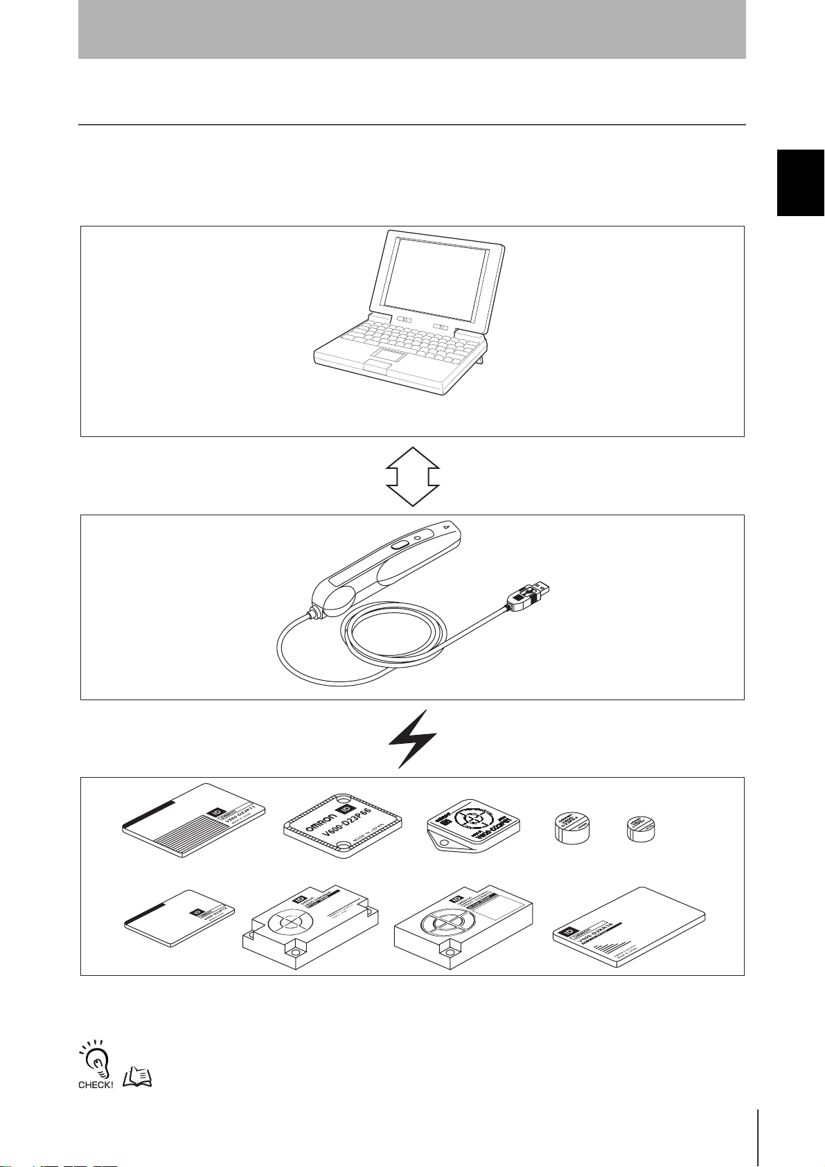
V600-CHUD
The V600-CHUD Hand-held Reader Writer can communicate with host devices that have a USB interface
such as personal computers.
Host Devices
Personal computer
Handheld Reader Writer
Section 1 System Configuration
Data Carriers
The V600-CHUD Hand-held Reader Writer can be used with any Data Carrier in the V600 Series.
For details on Hand-held Reader Writer and Data Carrier models, refer to Section 6 Appendices.
p.116, p.128
RFID System
User’s Manual
13
Page 16
Section 1
Product Overview
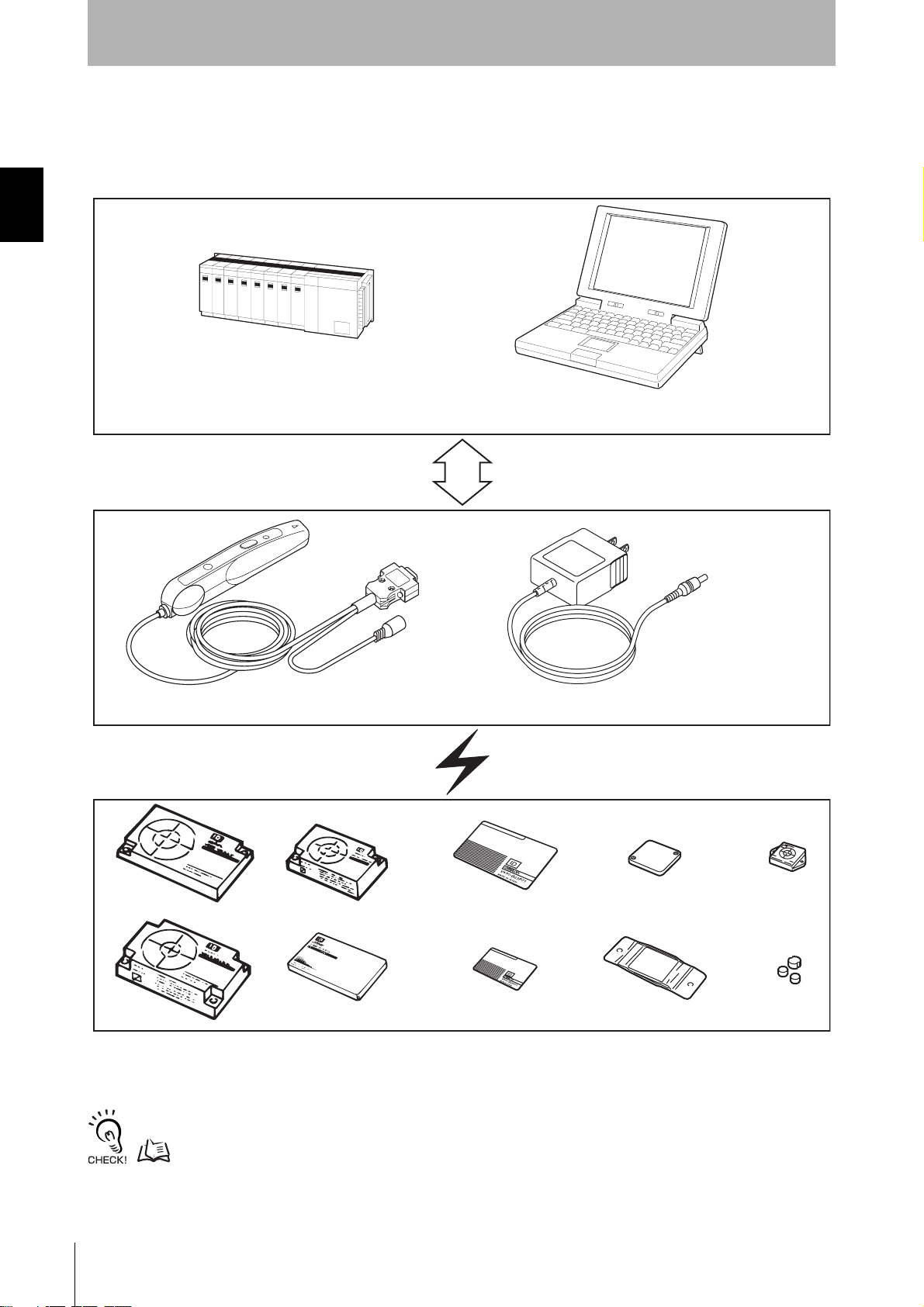
V600-CH1D-V2
A built-in RS-232C serial interface in the V600-CH1D-V2 Hand-held Reader Writer allows communication with
personal computers and programmable controllers that are equipped with an RS-232C interface.
Host Devices
Section 1System Configuration
Programmable controller
(Some models require a conversion connector.)
Personal computer
Hand-held Reader Writer
V600-CH1D-V2
Data Carriers
V600-A22 (option)
14
The V600-CH1D-V2 Hand-held Reader Writer can be used with any Data Carrier in the V600 Series.
For details on Hand-held Reader Writer and Data Carrier models, refer to Section 6 Appendices.
p.116, p.128
RFID System
User’s Manual
Page 17
Operation Flowchart
Section 1
Product Overview
V600-CHUD
Section 1 Operation Flowchart
Connect the V600-CHUD to the host device.
When connecting for the first time, the USB driver must be installed.
Preparation
Te st
p.18 p.19
Perform the communications test between the host device and
Hand-held Reader Writer.
p.38
Perform the communications test between the Data Carrier
and Hand-held Reader Writer.
Transmission
p.38
Check the ambient environment.
p.116
Operate the system using real commands.
p.39
RFID System
User’s Manual
15
Page 18
Section 1
Product Overview
V600-CH1D-V2
Connect the V600-CHUD to the host device.
When connecting for the first time, the USB driver must be installed.
Section 1Operation Flowchart
Preparation
Communications preparation
Te s t
p.18 p.19
Set the communications parameters between the host device and
Hand-held Reader Writer.
p. 32
Perform the communications test between the host device and
Hand-held Reader Writer.
p.38
Perform the communications test between the Data Carrier
and Hand-held Reader Writer.
p.38
Check the ambient environment.
p.116
Operate the system using real commands.
p.39
Transmission
16
RFID System
User’s Manual
Page 19
Section 2 Communications Preparations
Connections 18
Installing the USB Driver (V600-CHUD) 19
V600-CH1D-V2 Communications Preparation 32
Communications Test 37
Section 2 Communications Preparations
RFID System
User's Manual
17
Page 20
Section 2Connections
Section 2
Communications Preparations
Connections
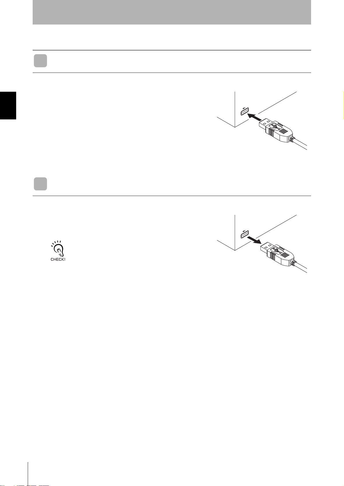
Connecting the Cable
1. Connect the cable connector to the USB connector on the host
device, making sure that the connector is oriented correctly
and not inserted at an angle.
Removing the Cable
1. Remove the cable.
Close the software application at the host device and then pull out the connector in a straight line.
If the connector is removed while the software is running at the host
device, operation may stop due to a software malfunction error.
18
RFID System
User's Manual
Page 21
Section 2
Communications Preparations
Installing the USB Driver (V600-CHUD)
When connecting the Hand-held Reader Writer to the host device for the first time, the USB driver must be
installed at the host device.
Install the USB Driver in the Personal Computer
The V600-CHUD supports Windows 2000 and Windows XP operating systems. Install the driver in the
host device following the procedure corresponding to the OS being used.
Operation on other OS is not supported.
• Windows 2000
1. Turn ON the power to the personal computer and start Windows 2000.
2. Connect the Hand-held Reader Writer to the personal computer.
For details on connection methods, refer to Connections.
p.18
Section 2 Installing the USB Driver (V600-CHUD)
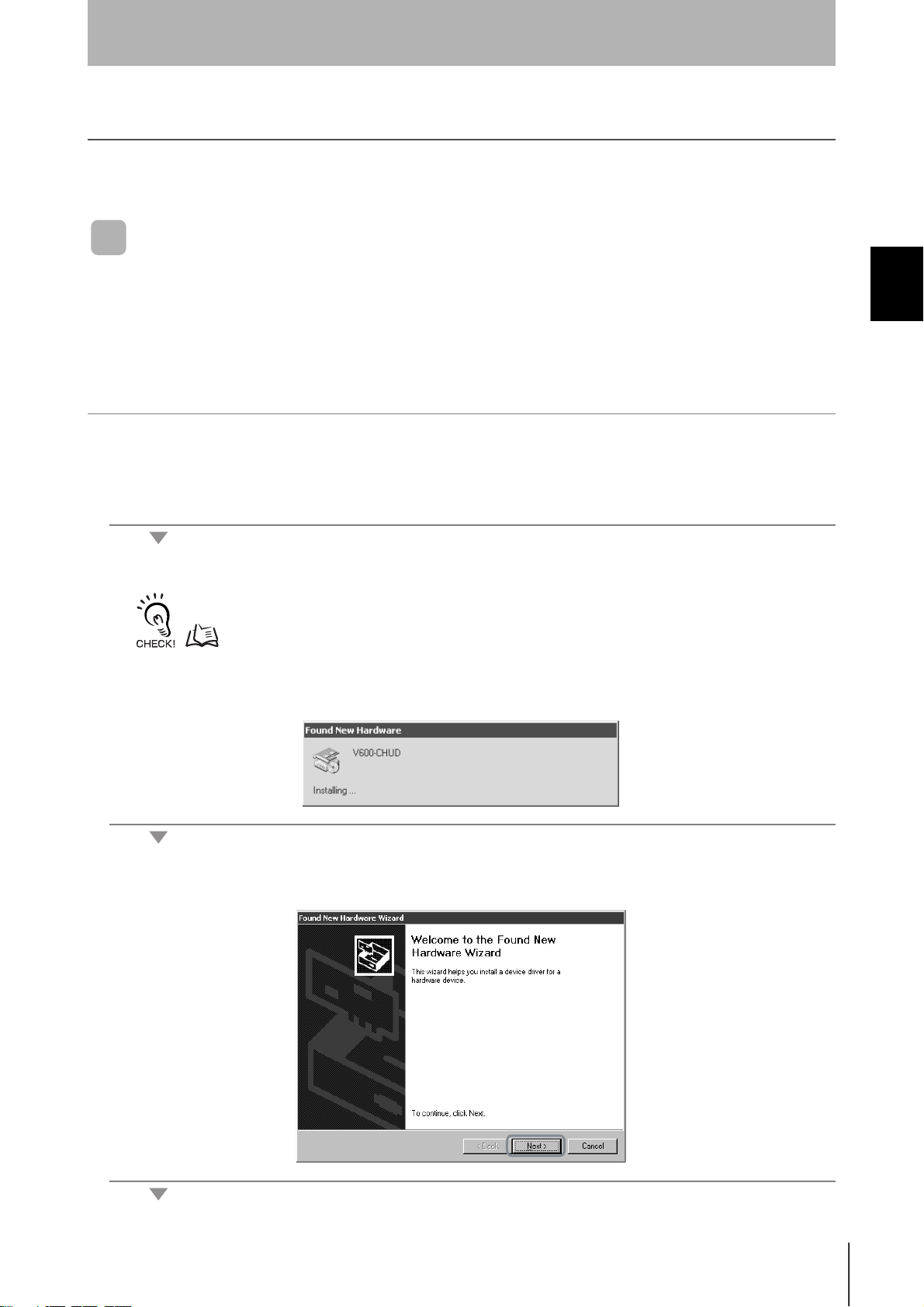
The following window will be displayed when the Hand-held Reader Writer is connected.
3. When the following window is displayed, click the Next Button.
RFID System
User's Manual
19
Page 22
Section 2Installing the USB Driver (V600-CHUD)
Section 2
Communications Preparations
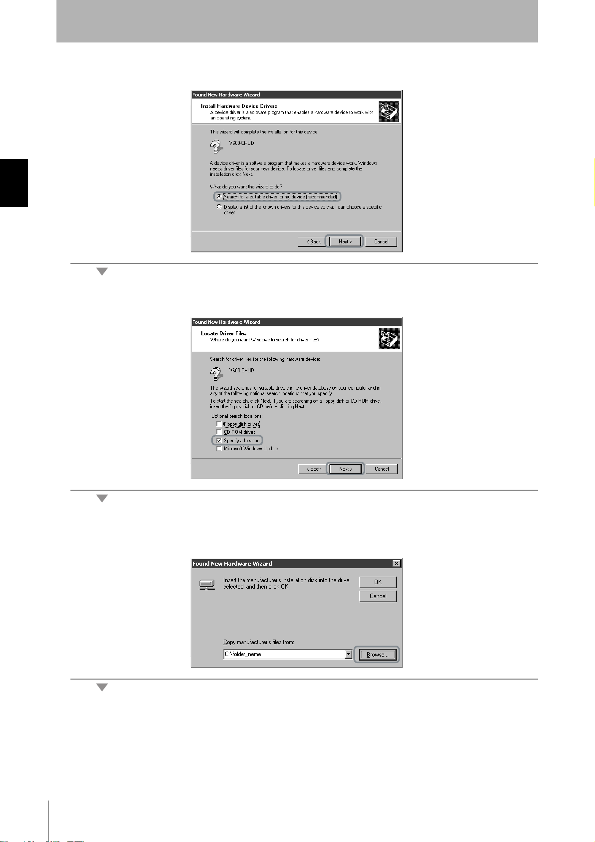
4. Select Search for a suitable driver for my device (recommended) and then click the Next Button.
5. Select Specify a location and then click the Next Button.
20
6. Click the Browse Button, and select the folder in which the downloaded file RFID-Win2kcom.inf is
saved.
RFID System
User's Manual
Page 23
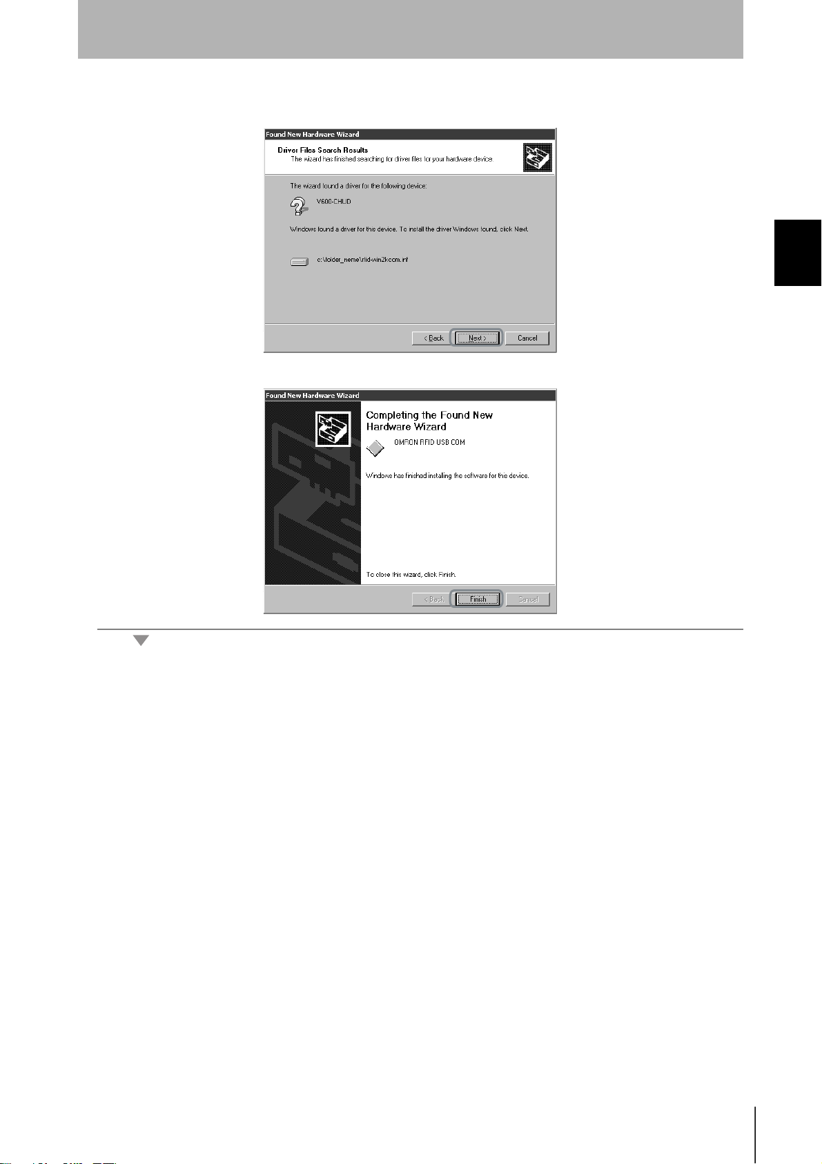
7. Click the Next Button.
The following window will be displayed when software installation is completed.
Section 2
Communications Preparations
Section 2 Installing the USB Driver (V600-CHUD)
8. Click the Finish Button.
RFID System
User's Manual
21
Page 24
Checking Installation
Section 2Installing the USB Driver (V600-CHUD)
Section 2
Communications Preparations
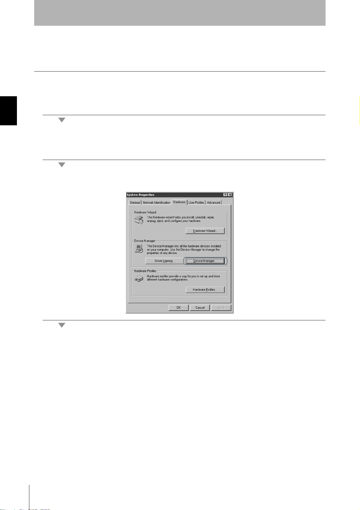
Check that the driver is correctly installed.
1. Connect the Hand-held Reader Writer to the personal computer.
2. On the Start Menu, select Settings - Control Panel - System.
3. Select the Device Manager Button on the Hardware Tab Page.
22
RFID System
User's Manual
Page 25
Communications Preparations
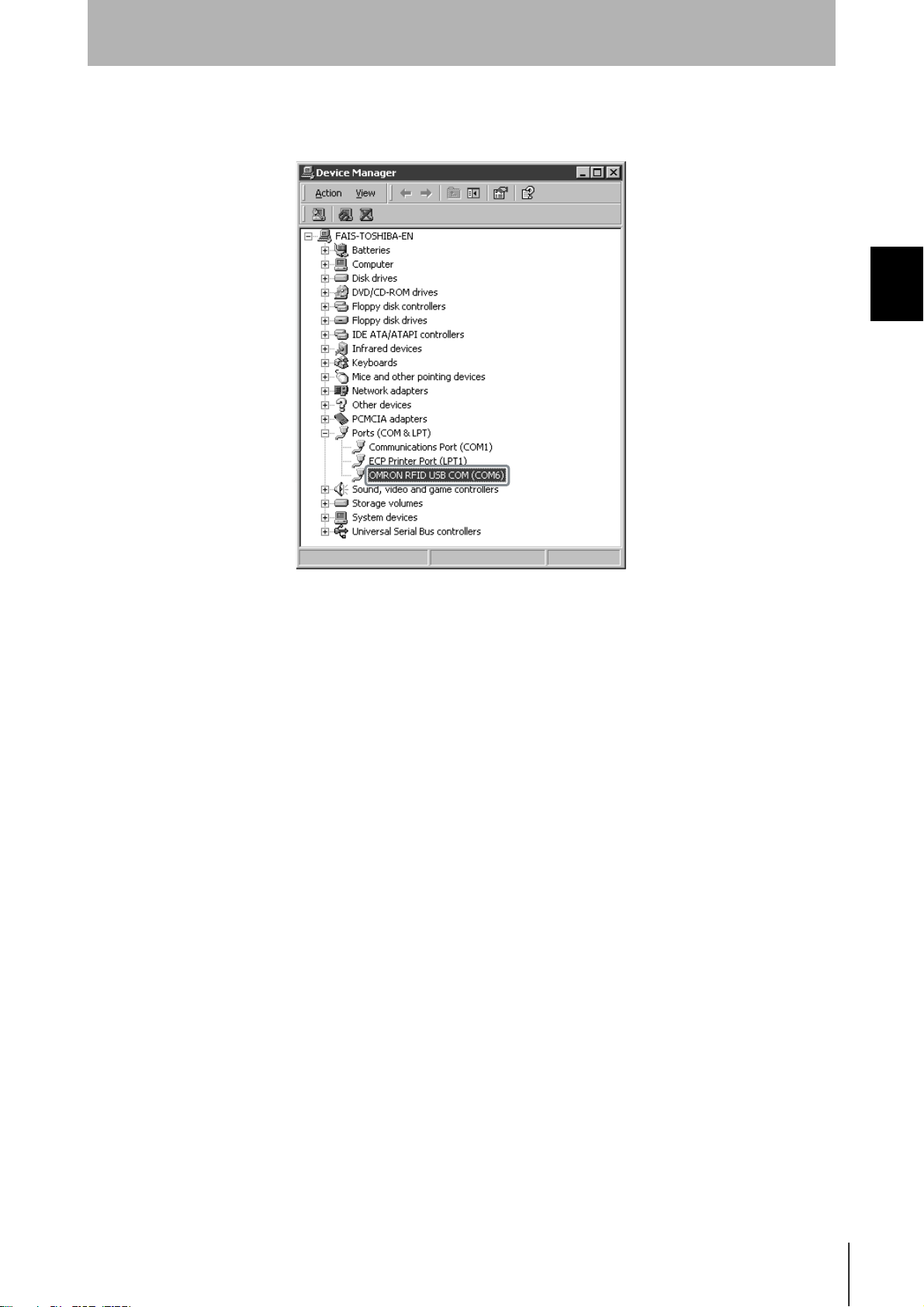
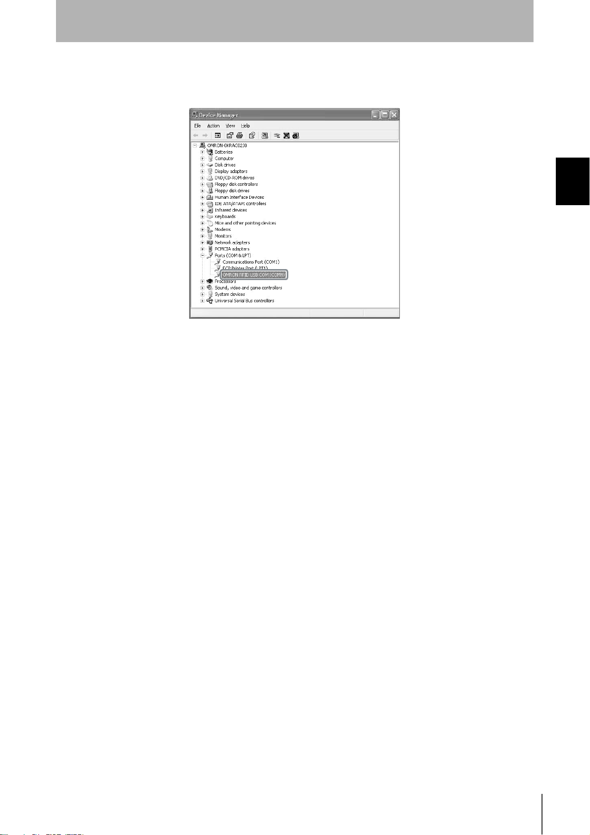
4. Select Por ts (COM & LPT), and check that OMRON RFID USB COM is displayed.
The driver is correctly installed if this port is displayed.
Section 2
Section 2 Installing the USB Driver (V600-CHUD)
Communications with the Hand-held Reader Writer can be performed with the COM number displayed in parentheses after
OMRON RFID USB COM.
RFID System
User's Manual
23
Page 26
Section 2
Communications Preparations
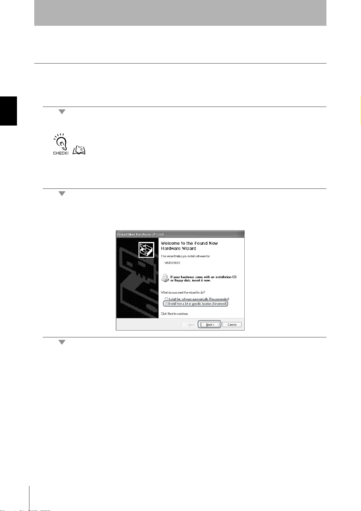
• Windows XP
1. Turn ON the power to the personal computer and start Windows XP.
Section 2Installing the USB Driver (V600-CHUD)
2. Connect the Hand-held Reader Writer to the personal computer.
For details on connection methods, refer to Connections.
p.18
Wait for the following window to be displayed.
3. When the following window is displayed, select Install from a list or specific location (Advanced)
and click the Next Button.
24
RFID System
User's Manual
Page 27
Section 2
Communications Preparations
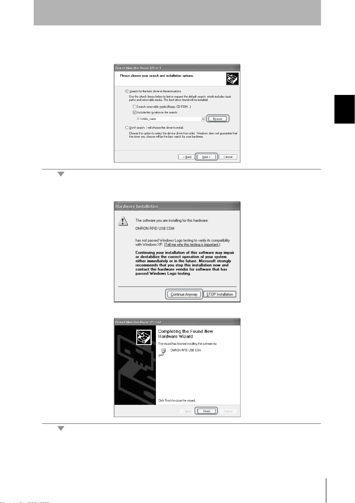
4. Click the Browse Button, and select the folder in which the downloaded file RFID-Win2kcom.inf is
saved. Then click the Next Button.
Section 2 Installing the USB Driver (V600-CHUD)
5. Click the Continue Anyway Button.
When the following window is displayed, installation is completed.
6. Click the Finish Button.
RFID System
User's Manual
25
Page 28
Section 2
Communications Preparations
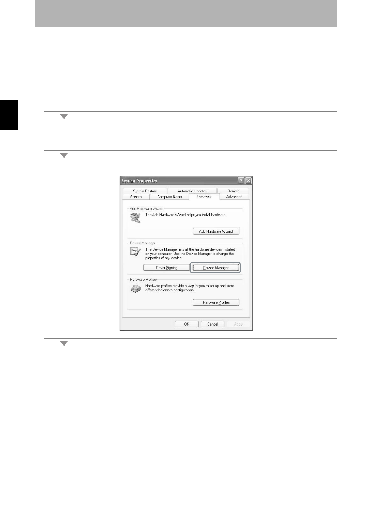
Checking Installation
Check that the driver is correctly installed.
1. Connect the Hand-held Reader Writer to the personal computer.
Section 2Installing the USB Driver (V600-CHUD)
2. On the Start Menu, select Control Panel - System.
3. Click the Device Manager Button in the Hardware Tab Page.
26
RFID System
User's Manual
Page 29
Communications Preparations
4. Select Por ts (COM & LPT), and check that OMRON RFID USB COM is displayed.
The driver is correctly installed if this port is displayed.
Section 2
Section 2 Installing the USB Driver (V600-CHUD)
Communications with the Hand-held Reader Writer can be performed with the COM number displayed in parentheses after
OMRON RFID USB COM.
RFID System
User's Manual
27
Page 30
Section 2
Communications Preparations
• Windows Vista
1. Turn ON the power to the personal computer and start Windows Vista.
Section 2Installing the USB Driver (V600-CHUD)
2. Connect the Hand-held Reader Writer to the computer via USB.
For details on connection methods, refer to Connections.
p.18
Wait for the following window to be displayed.
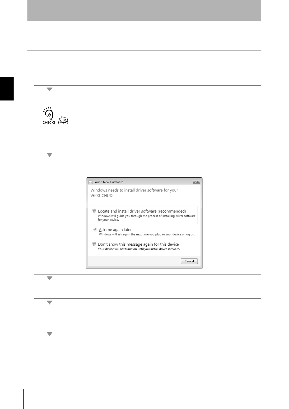
3. When the following window is displayed, select Locate and install driver software (recommended)
Button.
28
4. If the User Account Control Dialog Box is displayed, click the Continue Button.
5. If a dialog box appears for searching for software online, select the Don't search online Option. If this
dialog box is not displayed, go to the next step.
RFID System
User's Manual
Page 31

Section 2
Communications Preparations
6. When the following window is displayed, select I don’t have the disc. Show me other options. But-
ton.
Section 2 Installing the USB Driver (V600-CHUD)
7. When the following window is displayed, select Browse my computer for driver software
(advanced) Button.
8. Click the Browse Button, and select the folder in which the downloaded file V600_CHUD_200.inf is
saved. Then click the Next Button.
RFID System
User's Manual
29
Page 32

Section 2Installing the USB Driver (V600-CHUD)
Section 2
Communications Preparations
9. When the following window is displayed, select Install this driver software anyway Button.
When the following window is displayed, installation is completed.
30
10. Click the Close Button.
The displays that actually appear depend on your computer environment.
RFID System
User's Manual
Page 33

Checking Installation
Check that the driver is correctly installed.
Section 2
Communications Preparations
1. Connect the Hand-held Reader Writer to the personal computer.
2. On the Start Menu, select Control Panel - Performance and Maintenance.
3. Click the System Icon.
4. Click the Device Manager Button.
5. Select Por ts (COM & LPT), and check that OMRON RFID USB COM is displayed.
The driver is correctly installed if this port is displayed.
Section 2 Installing the USB Driver (V600-CHUD)
Communications with the Hand-held Reader Writer can be performed with the COM number displayed in parentheses after
OMRON RFID USB COM.
RFID System
User's Manual
31
Page 34

Section 2
Communications Preparations
V600-CH1D-V2 Communications Preparation
Pin Arrangement of the Host Device Interface Connector
V600-CH1D-V2
51
Pin No. Signal
Section 2V600-CH1D-V2 Communications Preparation
1 --- ---
2
3
4 --- --- ---
9
6
5 Signal ground SG ---
6
7 Request send RS Loops inside connector
8 Enable send CS
9 --- --- ---
Receive data RD Hand-held Reader Writer to
Send data SD Host device to Hand-held
Data set ready DS Hand-held Reader Writer to
Code
(See
note.)
Signal direction
host device
Reader Writer
host device
Note: The names of signals at the host device are abbreviated with
codes.
Note: For conversion to a 25-pin connector, the SGC-X9P/25P-2 manufactured by Sunhayato, or an
equivalent, is recommended.
32
RFID System
User's Manual
Page 35

•Connection with the Host Device
Use the following procedure to connect the V600-CH1D-V2 to the host device.
Section 2
Communications Preparations
1. Connect the V600-CH1D-V2 to the RS-232C interface of the host device.
•When connecting to an IBM PC/AT or compatible:
•When connecting to a PC9801 series computer (D-Sub 25-pin connector):
To convert from a 9-pin connector to a 25-pin connector, use an SGC-X9P25P-2 conversion connec-
tor manufactured by Sunhayato, or an equivalent product.
SGC-X9P25P-2
Section 2 V600-CH1D-V2 Communications Preparation
2. Connect the V600-A22 AC Adaptor to the V600-CH1D-V2.
3. Plug the V600-A22 AC Adaptor into a 100- to 120-VAC power outlet.
• Do not use any AC adaptor other than the specified one (V600-A22).
• Using any AC adaptor other than the specified one may cause a malfunction, damage, or fire in the V600-CH1D-V2.
• Some host devices require a conversion connector.
V600-A22
RFID System
User's Manual
33
Page 36

Section 2
Communications Preparations
When connecting to a CQM1, CJ1, CS1, etc.
Prepare a connection cable as shown in the connection examples below.
Note: Because both the V600-CH1D-V2 interface connector and the interface connector of the
CQM1, CJ1, and CS1 are sockets, a conversion connector is necessary to connect them. Also,
the pin arrangement of the CQM1, CJ1, and CS1 interface connector is different from the RS232C pin arrangement of a personal computer.
V600-CH1D-V2 CQM1/CJ1/CS1
Pin No. Signal Pin No. Signal
Section 2V600-CH1D-V2 Communications Preparation
1 --- 1 ---
2RD 2SD
3SD 3RD
4 --- 4 RS
5SG 5CS
6 DS 6 ---
7 RS 7 ---
8 CS 8 ---
9 --- 9 SG
34
RFID System
User's Manual
Page 37

Setting the Hand-held Reader Writer
•Settings
The following settings are used to operate the Hand-held Reader Writer.
•Serial communications parameters (data transfer speed, parity check, stop bits).
•Basic function settings (Auto Command OFF and Normal Operation Output functions)
These settings can be changed by using a setting command from the host device. To operate the
Hand-held Reader Writer with the new setting, the power must be turned OFF then ON again, or the
ABORT command must be used.
Serial Communications Parameters
The following are the settings related to serial communications. Use the COMMUNICATIONS CONDITIONS SETTING (TR) command.
Item Contents
Baud rate (bps) 2400, 4,800, 9,600 (see note), 19,200, 38,400
Transmission code 7-unit ASCII 7* (see note) or 8-unit JIS 8
Parity check Even parity* (see note)/odd parity/none
Stop bits 2* (see note)/1
Section 2
Communications Preparations
Section 2 V600-CH1D-V2 Communications Preparation
Note: Items marked by an asterisk (*) are set as the default when shipped from the factory.
Basic Function Settings
The Auto Command OFF and Normal Operation Output functions can be set. Use the BASIC FUNCTIONS SETTING (FN) command
Item Contents
Auto Command OFF
function
Normal Operation
Output function
Yes (1 minute)*, No
No*, Yes
Note: Items marked by an asterisk (*) are set as the default when shipped from the factory.
•Reading the Settings
Use the SET INFORMATION READ (UL) command to read the settings of the Hand-held Reader
Writer. The information read by the SET INFORMATION READ command is set in the backup memory
of the Hand-held Reader Writer. For this reason, care must be taken when the power is first turned ON
after the settings have been changed because the operational settings of the Hand-held Reader Writer
will be different.
•Initializing the Settings
A setting command is used to set the Hand-held Reader Writer but if the communications parameters
are not known or if the setting contents are damaged, it is possible that communications will no longer
be possible with the host device. If this occurs, press both the reset button and the activate switch
when turning ON the power. This will return all settings to the defaults set when the Hand-held Reader
Writer was shipped from the factory, allowing communications with the host device again.
RFID System
User's Manual
35
Page 38

Section 2
Communications Preparations
•Reset Procedure
1. Turn ON the power while pressing the reset button.
2. Keep the reset button depressed for two seconds or more. The green operation indicator will start
flashing.
Section 2V600-CH1D-V2 Communications Preparation
3. With the green operation indicator flashing, remove your finger from the reset button and press the acti-
vate switch.
4. When the activate switch is pressed, the operation indicator will stop flashing green. This indicates that
all of the settings have been initialized.
Note: If the activate switch is not pressed within 30 seconds from the time that the operation indicator
starts flashing green, the settings will not be initialized.
36
RFID System
User's Manual
Page 39

Communications Test
Test Run Procedure
Connect the Hand-held Reader Writer
to the host device.
Visually check the indicator display.
Section 2
Communications Preparations
Section 2 Communications Test
Execute the online test from the host
device.
Test run the system.
Finish
Check communications between the host device and Hand-held Reader
Writer using the test command.
Check operation using real commands.
RFID System
User's Manual
37
Page 40

Section 2
Communications Preparations
Communications Test Between Host Device and Hand-held
Reader Writer
Use the test command to test communications between the Hand-held Reader Writer and host device.
Before performing communications with the Data Carrier, check the Hand-held Reader Writer connections and communications.
1. Send the test command from the host device.
Section 2Communications Test
For detail on the test command, refer to TEST (TS).
p.89
2. If communications is normal, the Hand-held Reader Writer will return the received data.
If a response is not returned, refer to Troubleshooting.
p.111
Communications Test Between the Data Carrier and Hand-held
Reader Writer
Use a real command to test communications between the Data Carrier and the Hand-held Reader
Writer.
1. Send the auto read command (AR) from the host device.
38
For details on the auto read command, refer to AUTO READ (AR).
p.52
The Hand-held Reader Writer will communicate with the Data Carrier and the operation indicator will flash green.
2. Move the antenna section of the Hand-held Reader Writer close to the Data Carrier.
The Hand-held Reader Writer will read the data in the Data Carrier when the Hand-held Reader Writer moves within the communications range. As a result, the operation indicator will be light green and then turn OFF.
RFID System
User's Manual
Page 41

Section 3 Commands
Communications with the Data Carrier 40
Command and Response Format 44
Communications Commands 48
Communications Subcommands 88
Host Commands 89
Controller Control Commands 90
Other Commands 94
End code List 95
Section 3 Commands
RFID System
User’s Manual
39
Page 42

Section 3
Commands
Communications with the Data Carrier
There are 4 types of commands for communicating with the Data Carrier using the Hand-held Reader Writer.
•Normal commands
•Button commands
•Auto commands
•Button auto commands
Normal Commands
Normal commands are sent from the host device for communications with the Data Carrier, after the
antenna end of the Hand-held Reader Writer has been moved close to the Data Carrier.
1. Move the antenna end of the Hand-held Reader Writer close to the Data Carrier.
Section 3 Communications with the Data Carrier
1
Host device
2
Command
4
Response
Hand-held Reader Writer
Communications
with Data Carrier
Data Carrier
3
2. Commands are sent from the host device to the Hand-held Reader Writer.
3. The Hand-held Reader Writer communicates with the Data Carrier.
4. A response is returned from the Hand-held Reader Writer to the host device.
If communications are normal, the operation indicator (LED) lights green and then turns OFF.
If the Data Carrier is not detected within the Hand-held Reader Writer's communication area when the
command is sent from the host device, a Data Carrier Non-existent Error will occur.
At this time, the operation indicator will flash red.
40
RFID System
User's Manual
Page 43

Section 3
Commands
Button Commands
Button commands used to perform communications with the Data Carrier are activated when the activate switch is pressed after commands are sent from the host device, and the antenna end of the
Hand-held Reader Writer has been moved close to the Data Carrier.
Host device Data Carrier
Command
Response
Hand-held Reader Writer
Press
Communications
with Data Carrier
1. A command is sent from the host device to the Hand-held Reader Writer. As a result, the operation
indicator will light green.
2. Move the antenna end of the Hand-held Reader Writer close to the Data Carrier.
2
Section 3
l
Communications with the Data Carrier
3. Press the Hand-held Reader Writer activate switch.
4. The Hand-held Reader Writer communicates with the Data Carrier.
5. A response is returned to the host device from the Hand-held Reader Writer.
If communications are normal, the operation indicator (LED) lights green and then turns OFF.
If the Data Carrier is not detected within the Hand-held Reader Writer's communication area when the
activate switch is pressed, a Data Carrier Non-existent Error will occur.
At this time, the operation indicator will flash red.
RFID System
User's Manual
41
Page 44

Section 3
Commands
Auto Commands
Auto commands can execute communications with the Data Carrier when the antenna is moved near
the front of the Data Carrier after a command is sent from the host device.
Hos
t device
Hand-held Reader Writer
3
Data
Carrier
Section 3 Communications with the Data Carrier
1
Command
4
Response
Communications
with Data Carrier
1. A command is sent from the host device to the Hand-held Reader Writer.
2. The Hand-held Reader Writer enters the communication stand-by state with the Data Carrier, and the
operation indicator (LED) flashes green.
If the Data Carrier is not detected within one minute of sending the command, a timeout will occur and a Data Carrier
Non-existent Error will occur. As a result, the operation indicator will flash red.
3. Communications with the Data Carrier are performed when the antenna end of the Hand-held Reader
Writer is moved near the Data Carrier.
3
42
4. A response is returned from the Hand-held Reader Writer to the host device.
If communications end normally, the operation indicator (LED) lights green and then turns OFF.
RFID System
User's Manual
Page 45

Section 3
Commands
Button Auto Commands
Button auto commands execute auto commands after a command is sent from the host device and the activate
switch of the Hand-held Reader Writer is pressed.
Host device Data Carrier
Hand-held Re
ader Writer
2
Press
4
Section 3
1
Command
5
Response
Communications
with Data Carrier
1. A command is sent from the host device to the Hand-held Reader Writer.
2. Press the Hand-held Reader Writer activate switch.
3. The Hand-held Reader Writer enters the communication stand-by state with the Data Carrier, and the
operation indicator (LED) flashes green.
If the Data Carrier is not detected within one minute of sending the command, a timeout will occur and a Data Carrier
Non-existent Error will occur. As a result, the operation indicator will flash red.
4. Communications with the Data Carrier are performed when the antenna end of the Hand-held Reader
Writer is moved near the Data Carrier.
4
l
Communications with the Data Carrier
5. A response is returned from the Hand-held Reader Writer to the host device.
If communications end normally, the operation indicator (LED) lights green and then turns OFF.
RFID System
User's Manual
43
Page 46

Section 3
Commands
Command and Response Format
The format of commands sent between the host computer and the Hand-held Reader Writer and responses
returned from the Hand-held Reader Writer to the host computer is shown below. The command and
response both consist of a single frame. The frame (including the terminator) consists of up to 4,106
characters for commands and 4,102 characters for responses.
1 frame
Command code Data Terminator
×× ×× ×
2
n2
CR
Section 3 Command and Response Format
Name Description
Command code Command: Contains the two-character code (see page p.46).
Response: Contains the same code that was sent with the command.
Data Contains the details of the command and response, as follows:
•ASCII/hexadecimal code specification, processing specification, mode specification
•Processing area number specification
•Processing start address
•Number of bytes to be read, write data
Terminator Indicates end of command/response.
Specifying Data Code
Whether the read or write data is treated as an ASCII (or JIS 8) code or hexadecimal code is specified
in a command.
•ASCII (JIS 8 Code)
•One character of ASCII or JIS 8 code data occupies 1 byte (1 address) of the Data Carrier memory.
•Example of Specifying ASCII Code
WT 10A
Command code Start address
ASCII
setting
00 ROOM
1
Processing
area number
setting
Write data
N
CR
Terminator
•Data Carrier
Address
0010
0011
0012
0013
0014
4
4
5
4
4
F
"O"
D
"M"
2
"R"
F
"O"
E
"N"
44
RFID System
User's Manual
Page 47

•Hexadecimal Code
y
•One character is treated as a hexadecimal number. Therefore, only numerals 0 through 9 and A to F
can be accepted.
•Two characters of data occupy 1 byte (1 address) of the Data Carrier memory. Therefore, specify data
in 2-character units (in even numbers) when using a WRITE command. If an odd number of characters is specified by mistake, an error will occur.
•Example of Specifying Hexadecimal Code
WT 10H1
Hexa-
Command
code
decimal
code
setting
Process-
ing area
number
setting
00 9619
Start address
Write data Terminator
Section 3
Commands
CR
•Data Carrier
Address
0010
0011
1
9
1 b
9
6
te
Section 3
l
Command and Response Format
RFID System
User's Manual
45
Page 48

Section 3
Commands
Command List
Commands can be classified into four major types.
•Communications Commands
The following commands are used for communications with the Data Carrier.
Command code Command name Function Page
RD READ Reads memory data from the Data Carrier. p.48
WT WRITE Writes data to the memory of the Data Carrier. p.50
AR AUTO READ Reads data from the Data Carrier when the Data Carrier is within the
communications area.
AW AUTO WRITE Writes data to the memory of the Data Carrier when the Data Carrier is
Section 3 Command and Response Format
BR BUTTON READ Reads data from the memory of the Data Carrier when the activate
BW BUTTON WRITE Writes data to the memory of the Data Carrier when the activate switch
UR BUTTON AUTO
READ
UW BUTTON AUTO
WRITE
RC COPY READ Reads data to be copied using the COPY WRITE command from the
WC COPY WRITE Writes the data read using the COPY READ command to the Data
XR EXPANSION
DIVIDED READ
XW EXPANSION
DIVIDED WRITE
NR EXPANSION
DIVIDED
AUTO READ
NW EXPANSION
DIVIDED
AUTO WRITE
rd EXPANSION
BATCH READ
wt EXPANSION
BATCH WRITE
ar EXPANSION
BATCH
AUTO READ
aw EXPANSION
BATCH
AUTO WRITE
br EXPANSION
BATCH
BUTTON READ
bw EXPANSION
BATCH
BUTTON WRITE
ur EXPANSION
BATCH BUTTON
AUTO READ
within the communications area.
switch is pressed.
is pressed.
Reads data from the Data Carrier when the Data Carrier enters the
communications area after the activate switch is pressed.
Writes data to the memory of the Data Carrier when the Data Carrier
enters the communications area after the activate switch is pressed.
Data Carrier.
Carrier.
Divides and reads up to 2 Kbytes of data from the Data Carrier.
Divides and writes up to 2 Kbytes of data to the Data Carrier.
Divides and reads up to 2 Kbytes of data from the Data Carrier when
the Data Carrier enters the communications area. p.70
Divides and writes up to 2 Kbytes of data to the Data Carrier when the
Data Carrier enters the communications area. p.72
Reads up to 2 Kbytes of data from the Data Carrier in a batch.
Writes up to 2 Kbytes of data to the Data Carrier in a batch.
Reads up to 2 Kbytes of data from the Data Carrier in a batch when the
Data Carrier enters the communications area. p.76
Writes up to 2 Kbytes of data to the Data Carrier in a batch when the
Data Carrier enters the communications area. p.77
Reads up to 2 Kbytes of data from the Data Carrier in a batch after the
activate switch is pressed. p.78
Writes up to 2 Kbytes of data to the Data Carrier in a batch after the
activate switch is pressed. p.79
Reads up to 2 Kbytes of data from the Data Carrier in a batch when the
Data Carrier enters the communications area after the activate switch
is pressed.
p.52
p.54
p.56
p.58
p.60
p.62
p.64
p.65
p.66
p.68
p.74
p.75
p.80
46
RFID System
User's Manual
Page 49

Command code Command name Function Page
uw EXPANSION
BATCH BUTTON
AUTO WRITE
CW CALCULATION
WRITE
FL FILL Writes data for the specified number of write bytes beginning from the
fl EXPANSION
BATCH
FILL
MDC/K DATA CHECK Calculates or compares memory check codes in the Data Carrier. p.86
MDS OVERWRITE
COUNT CONTROL
Writes up to 2 Kbytes of data to the Data Carrier in a batch when the
Data Carrier enters the communications area after the activate switch
is pressed.
Writes the calculation results for the memory data to the Data Carrier.
write start address specified in the command.
Writes data for the specified number of write bytes beginning from the
write start address specified in the command. Up to 2 Kbytes of data
can be written in a batch.
Controls the number of overwrites for EEPROM Data Carriers.
•Communications Subcommands
These commands are used to cancel command execution.
Section 3
Commands
p.81
p.82
p.83
p.85
Section 3
p.87
l
Command and Response Format
Command code Command name Function Page
AA COMMAND PRO-
CESSING TERMINATE
•Host Commands
These commands are used to test communications between the Hand-held Reader Writer and host
device.
Command code Command name Function Page
TS TEST Confirms the communications status between the Hand-held Reader
VS VERSION READ Reads the Hand-held Reader Writer's model information, software ver-
•Controller Control Commands
These commands are used to reset the Controller or set serial communications.
Command code Command name Function Page
XZ ABORT Resets the Controller. p.90
TR COMMUNICA-
TIONS CONDITIONS SETTING
FN BASIC FUNC-
TIONS SETTING
UL SET INFORMA-
TION READ
Forcedly ends communications with the Data Carrier.
p.88
Writer and host device. The data sent from the host device is returned
as is.
sion and software creation date.
Sets communications parameters for communications with the host
device. p.91
Sets the Specify Auto Command OFF function and Specify Normal
Operation Output function.
Reads the settings data for the Hand-held Reader Writer.
p.89
p.89
p.92
p.93
RFID System
User's Manual
47
Page 50

Section 3 Communications Commands
(1)
g
g
Section 3
Commands
Communications Commands
Details of communications commands used to communicate with the Data Carrier are provided here.
READ (RD)
This command reads data from the Data Carrier. If the Data Carrier is not in the communications area,
an error response (end code: 72 = Data Carrier non-existent) will be returned.
Command
Processing area number: 1
Proc-
essing
area
Command
RD
Data
number
setting
code
211 4 2
setting
A/H 1
Read area
start address
××
Number of bytes
××
to read
××
Terminator
CR
2
Processing area number: 2
Proc-
essing
Command
code
RD
211 4 2
Data
setting
A/H 2
area
number
setting
Read area
start address
××
settin
Area
××
Data setting Sets the code format used to send responses for read data.
A: ASCII
H: Hexadecimal code
When multiple processing areas are used, ASCII and hexadecimal code can be specified at the
same time within a single command frame.
Processing area number
setting
Specifies the processing area number.
Setting range: 1 to 9, A (A = 10)
Read area start address Specifies the start address of the area to be read from the Data Carrier in 4-digit hexadecimal code.
Setting range: 0000h to 1FFFh
When multiple processing areas are used, specify the areas in order starting from the smallest
address. The same area cannot be specified twice.
Number of bytes to read Specifies the number of bytes to be read from the Data Carrier in 2-digit hexadecimal code. The
maximum number of bytes that can be read at one time is 256 bytes, as follows:
•ASCII: 256 bytes (256 characters)
•Hexadecimal code: 256 bytes (512 characters)
Number of
bytes
to read
××
Data
setting
A/H
1
××××
Number of bytes
to read
××
Read area
start address
42
Area (2) settin
Terminator
CR
2
48
RFID System
User's Manual
Setting range: 00h to FFh (00 = 256 bytes)
When multiple processing areas are used, set so that the total number of bytes from all areas to be
read is within 256 bytes, as follows:
Area (1) bytes +...+ Area (N) bytes
≤ 256 bytes
Page 51

Response
Processing Area Number: 1
Command
code
RD
00
22 n
Read dataEnd code
××
Terminator
×
×
CR
2
Processing Area Number: 2
Command
RD
End code
code
00
22 n
Read data
Area (1)
××
Area (1) setting
×
××
End code Indicates the execution result for the command.
The end code 00 indicates normal completion.
Read data
Area (2)
×
n
Area (2) setting
××
Terminator
CR
2
Section 3
Commands
Section 3
l
Communications Commands
For details on end codes, refer to End code List.
p.95
Read data Specifies the data read from the Data Carrier.
The characters in ASCII indicate the number of read bytes and the characters in hexadecimal code
indicate the number of read bytes x 2.
RFID System
User's Manual
49
Page 52

Section 3
g
Commands
WRITE (WT)
This command writes data to the Data Carrier. If the Data Carrier is not in the communications area, an
error response (end code: 72 = Data Carrier non-existent) will be returned.
Command
Processing Area Number: 1
Processing
area
Command
WT
Data
number
setting
code
211 4
setting
A/H 1
Write area
start address
××
××
Write data
××
n
××
Terminator
CR
2
Section 3 Communications Commands
Processing Area Number: 2
Processing
Command
code
WT
211 4 2
Data setting Sets the code format used to send responses for read data.
Processing area number
setting
Write area start address Specifies the start address of the area in the Data Carrier to be written to in 4-digit hexadecimal
Number of write bytes When multiple processing areas are used, specifies the number of bytes to be written to the Data
Data
setting
A/H 2
area
number
setting
××
Number of
write bytes
××
Write data
n
××
Data
setting
A/H
1
Write area
start address
××××
42
Area (2) settin
Number of
write bytes
××
Write data
n
Write area
start address
××
Area (1) setting
A: ASCII
H: Hexadecimal code
When multiple processing areas are used, ASCII and hexadecimal code can be specified at the
same time within a single command frame.
Specifies the processing area number.
Setting range: 1 to 9, A (A = 10)
code.
Setting range: 0000h to 1FFFh
When multiple processing areas are used, specify the areas in order starting from the smallest
address. The same area cannot be specified twice.
Carrier in 2-digit hexadecimal code. The maximum number of bytes that can be written at one time
is 256 bytes, as follows:
• ASCII: 256 bytes (256 characters)
• Hexadecimal code: 256 bytes (512 characters)
Setting range: 01h to FFh
Terminator
××
2
CR
50
Write data Specifies the write data from the Data Carrier.
RFID System
User's Manual
When multiple processing areas are used, set so that the total number of bytes to be written for all
areas is within 256 bytes, as follows:
Area (1) bytes +...+ Area (N) bytes
≤ 256 bytes
The characters in ASCII indicate the number of write bytes and the characters in hexadecimal code
indicate the number of write bytes x 2.
Page 53

Response
Command
code
WT
End code Indicates the execution result for the command.
End code
00
22
Terminator
CR
2
The end code 00 indicates normal completion.
For details on end codes, refer to End code List.
p.95
Section 3
Commands
Section 3
l
Communications Commands
RFID System
User's Manual
51
Page 54

Section 3
Commands
AUTO READ (AR)
This command reads data from the Data Carrier when the Data Carrier enters the communications
area. The Hand-held Reader Writer responds when the communication between the Hand-held
Reader Writer and Data Carrier has ended.
Command
Processing Area Number: 1
Processing
area
Command
AR
Data
number
setting
code
211 4 2
setting
A/H 1
Read area
start address
××
××
Number of
read bytes
××
Terminator
CR
2
Section 3 Communications Commands
Processing Area Number: 2
Processing
area
Command
AR
Data
number
setting
code
211 4 2
setting
A/H 2
Data setting Specifies the code format used to send responses for read data.
Processing area number
setting
Read area start address Specifies the start address of the area in the Data Carrier to be read from in 4-digit hexadecimal
Number of read bytes When multiple processing areas are used, specifies the number of bytes to be read from the Data
Read area
start address
××
Area (1) setting
××
Number of
read bytes
××
Data
setting
A/H
1
Read area
start address
××××
42
Area (2) setting
Number of
read bytes
××
Terminator
CR
2
A: ASCII
H: Hexadecimal code
When multiple processing areas are used, ASCII and hexadecimal code can be specified at the
same time within a single command frame.
Specifies the processing area number.
Setting range: 1 to 9, A (A = 10)
code.
Setting range: 0000h to 1FFFh
When multiple processing areas are used, specify the areas in order starting from the smallest
address. The same area cannot be specified twice.
Carrier in 2-digit hexadecimal code.
The maximum number of bytes that can be read at one time is 256 bytes.
•ASCII: 256 bytes (256 characters)
•Hexadecimal code: 256 bytes (512 characters)
Setting range: 00h to FFh (00 = 256 bytes)
52
RFID System
User's Manual
When multiple processing areas are used, set so that the total number of bytes to be read for all
areas is within 256 bytes, as follows:
Area (1) bytes +...+ Area (N) bytes
≤ 256 bytes
Page 55

Response
g
Processing Area Number: 1
Command
code
AR
00
22 n
Read dataEnd code
××
Processing Area Number: 2
Section 3
Commands
Terminator
×
×
CR
2
Command
code
AR
End code
00
22 n
Read data
area (1)
××
Area (1) setting
×
××
Read data
area (2)
×
n
Area (2) settin
××
End code Indicates the execution result for the command.
The end code 00 indicates normal completion.
For details on end codes, refer to End code List.
p.95
Read data Specifies the data read from the Data Carrier.
The characters in ASCII indicate the number of read bytes and the characters in hexadecimal code
indicate the number of read bytes x 2.
Terminator
CR
2
Section 3
l
Communications Commands
RFID System
User's Manual
53
Page 56

Section 3
Commands
AUTO WRITE (AW)
This command writes data to the Data Carrier when the Data Carrier enters the communications area.
The Hand-held Reader Writer responds when communications between the Hand-held Reader Writer
and Data Carrier have ended.
Command
Processing Area Number: 1
Processing
Command
code
AW
211 4
Data
setting
A/H 1
area
number
setting
Write area
start address
××
××
Write data
××
n
××
Terminator
CR
2
Section 3 Communications Commands
Processing Area Number: 2
Processing
Command
code
AW
211 4 2
Data setting Sets the code format used to send responses for read data.
Processing area number
setting
Write area start address Specifies the start address of the area in the Data Carrier to be written to in 4-digit hexadecimal
Number of write bytes When multiple processing areas are used, specifies the number of bytes to be written to the Data
Data
setting
A/H 2
area
number
setting
Write area
start address
××
Area (1) setting
××
Number of
write bytes
××
Write data
Data
setting
××
n
1
Write area
start address
××××
42
Area (2) setting
Number of
write bytes
××
Write data
n
A: ASCII
H: Hexadecimal code
When multiple processing areas are used, ASCII and hexadecimal code can be specified at the
same time within a single command frame.
Specifies the processing area number.
Setting range: 1 to 9, A (A = 10)
code.
Setting range: 0000h to 1FFFh
When multiple processing areas are used, specify the areas in order starting from the smallest
address. The same area cannot be specified twice.
Carrier in 2-digit hexadecimal.
The maximum number of bytes that can be written at one time is 256 bytes.
•ASCII: 256 bytes (256 characters)
•Hexadecimal code: 256 bytes (512 characters)
Setting range: 01h to FFh
Terminator
××
2
CRA/H
54
Write data Indicates the data to be written to the Data Carrier.
RFID System
User's Manual
When multiple processing areas are used, set so that the total number of bytes to be written for all
areas is within 256 bytes,6 bytes, as follows:
Area (1) bytes +...+ Area (N) bytes
≤ 256 bytes
The characters in ASCII indicate the number of write bytes and the characters in hexadecimal code
indicate the number of write bytes × 2
Page 57

Response
Section 3
Commands
Command
code
AW
End code Indicates the execution result for the command.
End code
00
22
Terminator
CR
2
The end code 00 indicates normal completion.
For details on end codes, refer to End code List.
p.95
Section 3
l
Communications Commands
RFID System
User's Manual
55
Page 58

Section 3
(1)
g
g
Commands
BUTTON READ (BR)
After this command is received by the Hand-held Reader Writer, data is read from the Data Carrier by
pressing the activate switch. If the activate switch is pressed and the Data Carrier is not in communications range, an error response (end code: 72 = Data Carrier non-existent) will be returned.
Command
Processing Area Number: 1
Processing
Command
code
BR
211 4 2
Data
setting
A/H 1
area
number
setting
Read area
start address
××
××
Number of
read bytes
××
Terminator
CR
2
Section 3 Communications Commands
Processing Area Number: 2
Command
code
BR
211 4 2
Data
setting
A/H 2
Processing
area number
setting
××
Read area
start address
settin
Area
××
Data setting Sets the code format used to send responses for read data.
A: ASCII
H: Hexadecimal code
When multiple processing areas are used, ASCII and hexadecimal code can be specified at the
same time within a single command frame.
Processing area number
setting
Specifies the processing area number.
Setting range: 1 to 9, A (A = 10)
Read area start address Specifies the start address of the area in the Data Carrier to be read from in 4-digit hexadecimal
code.
Setting range: 0000h to 1FFFh
When multiple processing areas are used, specify the areas in order starting from the smallest
address. The same area cannot be specified twice.
Number of read bytes Specifies the number of bytes to be read from the Data Carrier in 2-digit hexadecimal.
The maximum number of bytes that can be read at one time is 256 bytes.
•ASCII: 256 bytes (256 characters)
•Hexadecimal code: 256 bytes (512 characters)
Setting range: 00h to FFh (00 = 256 bytes)
Number of
read bytes
××
Data
setting
A/H
1
Read area
start address
42
Area (2) settin
Number of
read bytes
××××
××
Terminator
CR
2
56
RFID System
User's Manual
When multiple processing areas are used, set so that the total number of bytes to be read for all
areas is within 256 bytes, as follows:
Area (1) bytes +...+ Area (N) bytes
≤ 256 bytes
Page 59

Response
g
g
Processing Area Number: 1
Command
code
End code
BR
00
22 n
Read data
××
Processing Area Number: 2
Section 3
Commands
Terminator
×
×
CR
2
Command
code
BR
End code
00
22 n
Read data
area (1)
××
Area (1) settin
×
××
Read data
area (2)
×
n
Area (2) settin
××
End code Indicates the execution result for the command.
The end code 00 indicates normal completion.
For details on end codes, refer to End code List.
p.95
Read data Indicates the data read from the Data Carrier.
The characters in ASCII indicate the number of read bytes and the characters in hexadecimal code
indicate the number of read bytes x 2.
Terminator
CR
2
Section 3
l
Communications Commands
RFID System
User's Manual
57
Page 60

Section 3 Communications Commands
g
(2)
g
Section 3
Commands
BUTTON WRITE (BW)
After this command is received by the Hand-held Reader Writer, data is written to the Data Carrier by
pressing the activate switch. If the activate switch is pressed and the Data Carrier is not in communications range, an error response (end code: 72 = Data Carrier non-existent) will be returned.
Command
Processing Area Number: 1
Processing
Command
code
BW
211 4
Processing Area Number: 2
Command
code
BW
211 4 2
Data
setting
A/H 1
Data
setting
A/H 2
area
number
setting
Processing
area number
setting
××
Write area
start address
××
Write area
start address
××
××
Number of
write bytes
××
Write data
××
n
Write data
××
××
n
Terminator
CR
2
Data
setting
A/H
1
Write area
start address
××××
42
Number of
write bytes
××
Write data
n
Terminator
××
CR
2
Area (1) settin
Area
settin
Data setting Sets the code format used to send responses for read data.
A: ASCII
H: Hexadecimal code
When multiple processing areas are used, ASCII and hexadecimal code can be specified at the
same time within a single command frame.
Processing area number
setting
Specifies the processing area number.
Setting range: 1 to 9, A (A = 10)
Write area start address Specifies the start address of the area in the Data Carrier to be written to in 4-digit hexadecimal
code.
Setting range: 0000h to 1FFFh
When multiple processing areas are used, specify the areas in order starting from the smallest
address. The same area cannot be specified twice.
Number of write bytes When multiple processing areas are used, specifies the number of bytes to be written to the Data
Carrier in 2-digit hexadecimal.
The maximum number of bytes that can be written at one time is 256 bytes.
•ASCII: 256 bytes (256 characters)
•Hexadecimal code: 256 bytes (512 characters)
Setting range: 01h to FFh
When multiple processing areas are used, set so that the total number of bytes to be written for all
areas is within 256 bytes, as follows:
Area (1) bytes +...+ Area (N) bytes
≤ 256 bytes
Write data Indicates the data to be written to the Data Carrier.
The characters in ASCII indicate the number of write bytes and the characters in hexadecimal code
indicate the number of write bytes x 2.
58
RFID System
User's Manual
Page 61

Response
Command
code
BW
End code Indicates the execution result for the command.
End code
00
22
Terminator
CR
2
The end code 00 indicates normal completion.
Section 3
Commands
For details on end codes, refer to End code List.
p.95
Section 3
l
Communications Commands
RFID System
User's Manual
59
Page 62

Section 3 Communications Commands
g
Section 3
Commands
BUTTON AUTO READ (UR)
After this command is received by the Hand-held Reader Writer, data will be read from the Data Carrier
after the activate switch is pressed and the Hand-held Reader Writer is close to the Data Carrier. The
Hand-held Reader Writer responds when communications between the Hand-held Reader Writer and
Data Carrier have ended.
Command
Processing Area Number: 1
Processing
Command
code
UR
211 4 2
Data
setting
A/H 1
area
number
setting
Processing Area Number: 2
Processing
area
Command
UR
Data
number
setting
code
211 4 2
setting
A/H 2
Read area
start address
××
Read area
start address
××
××
××
Number of
read bytes
××
Number of
read bytes
××
Terminator
2
Data
setting
A/H
1
CR
Read area
start address
Number of
read bytes
××××
42
××
Terminator
CR
2
Area (1) settin
Area (2) setting
Data setting Sets the code format used to send responses for read data.
A: ASCII
H: Hexadecimal code
When multiple processing areas are used, ASCII and hexadecimal code can be specified at the
same time within a single command frame.
Processing area number
setting
Specifies the processing area number.
Setting range: 1 to 9, A (A = 10)
Read area start address Specifies the start address of the area in the Data Carrier to be read from in 4-digit hexadecimal
code.
Setting range: 0000h to 1FFFh
When multiple processing areas are used, specify the areas in order starting from the smallest
address. The same area cannot be specified twice.
Number of read bytes Specifies the number of bytes to be read from the Data Carrier in 2-digit hexadecimal.
The maximum number of bytes that can be read at one time is 256 bytes.
•ASCII: 256 bytes (256 characters)
•Hexadecimal code: 256 bytes (512 characters)
Setting range: 00h to FFh (00 = 256 bytes)
When multiple processing areas are used, set so that the total number of bytes to be read for all
areas is within 256 bytes, as follows:
Area (1) bytes +...+ Area (N) bytes
≤ 256 bytes
60
RFID System
User's Manual
Page 63

Response
(1)
g
g
Processing Area Number: 1
Command
code
End code
UR
00
22 n
××
Processing Area Number: 2
Section 3
Commands
TerminatorRead data
×
×
CR
2
Command
code
UR
End code
00
22 n
Read data
area (1)
××
Area
settin
×
××
Read data
area (2)
××
n
Area (2) settin
End code Indicates the execution result for the command.
The end code 00 indicates normal completion.
For details on end codes, refer to End code List.
p.95
Read data Indicates the data read from the Data Carrier.
The characters in ASCII indicate the number of read bytes and the characters in hexadecimal code
indicate the number of read bytes x 2.
Terminator
CR×
2
Section 3
l
Communications Commands
RFID System
User's Manual
61
Page 64

Section 3 Communications Commands
Section 3
Commands
BUTTON AUTO WRITE (UW)
After this command is received by the Hand-held Reader Writer, data will be written to the Data Carrier
after the activate switch is pressed and the Hand-held Reader Writer is close to the Data Carrier. The
Hand-held Reader Writer responds when communications between the Hand-held Reader Writer and
Data Carrier have ended.
Command
Processing Area Number: 1
Processing
Command
code
UW
211 4
Processing Area Number: 2
Command
code
UW
211 4 2
Data
setting
A/H 1
Data
setting
A/H 2
area
number
setting
Processing
area
number
setting
Write area
start address
××
Write area
start address
××
××
××
××
Number of
write bytes
××
Write data
n
Write data
××
××
n
Terminator
CR
2
Data
setting
A/H
1
Write area
start address
××××
42
Number of
write bytes
××
Write data
n
××
Terminator
CR
2
Area (1) setting
Area (2) setting
Data setting Sets the code format used to send responses for read data.
A: ASCII
H: Hexadecimal code
When multiple processing areas are used, ASCII and hexadecimal code can be specified at the
same time within a single command frame.
Processing area number
setting
Specifies the processing area number.
Setting range: 1 to 9, A (A = 10)
Write area start address Specifies the start address of the area in the Data Carrier to be written to in 4-digit hexadecimal
code.
Setting range: 0000h to 1FFFh
When multiple processing areas are used, specify the areas in order starting from the smallest
address. The same area cannot be specified twice.
Number of write bytes When multiple processing areas are used, specifies the number of bytes to be written to the Data
Carrier in 2-digit hexadecimal.
The maximum number of bytes that can be written at one time is 256 bytes.
•ASCII: 256 bytes (256 characters)
•Hexadecimal code: 256 bytes (512 characters)
Setting range: 01h to FFh
When multiple processing areas are used, set so that the total number of bytes to be written for all
areas is within 256 bytes, as follows:
Area (1) bytes +...+ Area (N) bytes
≤ 256 bytes
Write data Indicates the data to be written to the Data Carrier.
The characters in ASCII indicate the number of write bytes and the characters in hexadecimal code
indicate the number of write bytes x 2.
62
RFID System
User's Manual
Page 65

Response
Section 3
Commands
Command
UW
End code Indicates the execution result for the command.
End code
code
00
22
Terminator
CR
2
The end code 00 indicates normal completion.
For details on end codes, refer to End code List.
p.95
Section 3
l
Communications Commands
RFID System
User's Manual
63
Page 66

Section 3 Communications Commands
Section 3
Commands
COPY READ (RC)
This command reads data to be copied using the COPY WRITE (WC) command.
A response is not sent for read data.
CommandCommand
Processing
Command
code
RC
2 1 1 0 or 4
Data
setting
H1
area
number
setting
Data setting Always H.
Processing area number
setting
Read area start address Specifies the start address of the area in the Data Carrier to be read from in 4-digit hexadecimal
Number of read bytes Specifies the number of bytes to be read from the Data Carrier in 4-digit hexadecimal.
Read area
start address
××
××
Number of
read bytes
××
0 or 4
××
Terminator
CR
2
Always 1.
code (can be omitted).
Setting range: 0000h to 1FFFh (when omitted, all areas in the Data Carrier are read)
Note: If omitting the start address, also omit the number of read bytes. All areas of an 8-Kbytes
Data Carrier cannot be copied.
Setting range: 0001h to 0800h
Response
Command
code
RC
End code
00
22
Terminator
CR
2
End code Indicates the execution result for the command.
The end code 00 indicates normal completion.
For details on end codes, refer to End code List.
p.95
The COPY READ command can be executed more than once for data that has already been copied. If the
copy operation fails, however, the copied data that was held will be deleted.
64
RFID System
User's Manual
Page 67

Section 3
r
Commands
COPY WRITE (WC)
This command writes data to the Data Carrier that was read using the COPY READ (RC) command.The Hand-held Reader Writer responds when communications between the Hand-held Reader
Writer and Data Carrier have ended.
Command
Processing
Command
code
WC
211
Data setting Always H.
Processing area number
setting
Response
Data
number
setting
H1
area
setting
Terminato
CR
2
Always 1.
Section 3
l
Communications Commands
Command
code
End code
WC
00
22
Terminator
CR
2
End code Indicates the execution result for the command.
The end code 00 indicates normal completion.
For details on end codes, refer to End code List.
p.95
RFID System
User's Manual
65
Page 68

Section 3 Communications Commands
Section 3
Commands
EXPANSION DIVIDED READ (XR)
This command divides and reads up to 2 Kbytes of data. If the Data Carrier is not in communications
range, an error response (end code: 72 = Data Carrier non-existent) will be returned. The host device
cannot send commands to the Hand-held Reader Writer until all the responses have been received.
Command
Processing
Command
code
XR
211 4
Data
setting
A/H 1
area
number
setting
Data setting Sets the code format used to send responses for read data.
Processing area number
setting
Read area start address Specifies the start address of the area in the Data Carrier to be read from in 4-digit hexadecimal
Number of read bytes Specifies the number of bytes to be read from the Data Carrier in 4-digit hexadecimal.
Read area
start address
××
××
Number of
read bytes
××
4
××
Terminator
CR
2
A: ASCII
H: Hexadecimal code
Always 1.
code.
Setting range: 0000h to 1FFFh
The maximum number of bytes that can be read at one time is 2,048 bytes.
Setting range: 0001h to 0800h
•ASCII: 2,048 bytes (2,048 characters)
•Hexadecimal code: 2,048 bytes (4,096 characters)
Response
When the read data is within 250 characters.
Command
code
XR
00
22 n
End code Indicates the execution result for the command.
Read data Indicates the data read from the Data Carrier.
Read dataEnd code
××
×
×
Terminator
CR
2
The end code 00 indicates normal completion.
For details on end codes, refer to End code List.
p.95
The characters in ASCII indicate the number of read bytes and the characters in hexadecimal code
indicate the number of read bytes x 2.
66
RFID System
User's Manual
Page 69

Section 3
p
Commands
When the read data is 251 characters or higher.
The data received from the host device is divided into frames according to the delimiters (CR), as
shown in the following diagram.
XR
Frame 1
Frame 2
00
:
Frame
(n-1)
Frame n
Communications Procedure
Command
Host
XR CR CR CR CR
256 characters max. per frame
Read data 2
Read data (n-1)
254 characters max.
Read data n
Delimiter
250 characters
Read data 1
254 characters
Delimiter
...
CR
CR
CR
CR
Delimiter Delimiter
Section 3
l
Communications Commands
Hand-held Reader Writer
Frame 1 Frame 2 Frame nFrame n-1
Res
onse 1 Response 2 Response nResponse n-1
RFID System
User's Manual
67
Page 70

Section 3 Communications Commands
Section 3
Commands
EXPANSION DIVIDED WRITE (XW)
Divides and writes up to 2 Kbytes of data. If the Data Carrier is not in communications range, an error
response (end code: 72 = Data Carrier non-existent) will be returned.
The host device cannot send commands to the Hand-held Reader Writer until all the responses have
been received.
Command
Frame 1
Processing
Command
code
XW
211 4
Data
setting
A/H 1
area
number
setting
Data setting Specifies the code format used to send write data to the Data Carrier.
Processing area number
setting
Write area start address Specifies the start address of the area to be written to in 4-digit hexadecimal.
Write data Indicates the data to be written to the Data Carrier.
Terminator Indicates the end of the frame.
Write area
start address
××
××
Write data
××
n
××
A: ASCII
H: Hexadecimal code
Always 1.
Setting range: 0000h to 1FFFh
Data can be between 0 and 257 characters.
CR: Succeeding frame
*CR: No succeeding frame
Terminator
CR
1or2
Frames 2 to N
Write data
××××
××
n
××
Write data Indicates the data to be written to the Data Carrier.
Data can be between 0 and 265 characters.
Terminator Indicates the end of the frame.
CR: Succeeding frame
*CR: No succeeding frame
Response
Command
code
XW
End code
00
22
Terminator
CR
2
End code Indicates the execution result for the command.
The end code 00 indicates normal completion.
For details on end codes, refer to End code List.
Terminator
CR
1or2
p.95
68
RFID System
User's Manual
Page 71

Section 3
Commands
•Frame Division Method
If the command length is longer than 266 characters, divide the data into separate frames before sending as follows:
Frame Division Method
1. Divide the data into frames each with 266 characters max.
2. Use the final terminator (* CR) for the last frame (frame n) only. Use the delimiter (CR) at the end of
other frames.
3. Be sure to include the command code, data setting, processing area number setting, and start address
in the first frame (frame 1). If any of these parameters is omitted, a command input error will occur. The
write data can be omitted.
4. Make sure that data is divided correctly without any single frames containing AA*CR or XZ*CR.
266 characters max. per frame
Section 3
l
Communications Commands
Frame 1
Frame 2
Frame (n-1)
Frame n
XW
::
Communications Procedure
Command 1
Host
Hand-held Reader Writer
XW
CR CR CR
Delimiter
A/H 1
Command 2 Command n-1 Command n
Start address Write data 1
Write data 2
Write data (n-1)
Write data n
...
Delimiter Delimiter
CR
Delimiter
CR
CR
CR
CR
CR
Response
RFID System
User's Manual
69
Page 72

Section 3 Communications Commands
Section 3
Commands
EXPANSION DIVIDED AUTO READ (NR)
This command divides and reads up to 2 Kbytes of data from the Data Carrier when the Hand-held
Reader Writer is moved close to the Data Carrier. The Hand-held Reader Writer responds when communications between the Hand-held Reader Writer and Data Carrier have ended. The host device cannot send commands to the Hand-held Reader Writer until all the responses have been received.
Command
Processing
Command
code
NR
211 4
Data
setting
A/H 1
area
number
setting
Read area
start address
××
××
Data setting Sets the code format used to send responses for read data.
A: ASCII
H: Hexadecimal code
Processing area number
Always 1.
setting
Read area start address Specifies the start address of the area in the Data Carrier to be read from in 4-digit hexadecimal
code.
Setting range: 0000h to 1FFFh
Number of read bytes Specifies the number of bytes to be read from the Data Carrier in 4-digit hexadecimal.
The maximum number of bytes that can be read at one time is 2,048 bytes.
Setting range: 0001h to 0800h
•ASCII: 2,048 bytes (2,048 characters)
•Hexadecimal code: 2,048 bytes (4,096 characters)
Number of
read bytes
××
4
××
Terminator
CR
2
Response
When the read data is within 250 characters.
Command
code
NR
00
22 n
End code Indicates the execution result for the command.
Read data Indicates the data read from the Data Carrier.
Read dataEnd code
××
×
×
Terminator
CR
2
The end code 00 indicates normal completion.
For details on end codes, refer to End code List.
p.95
The characters in ASCII indicate the number of read bytes and the characters in hexadecimal code
indicate the number of read bytes x 2.
70
RFID System
User's Manual
Page 73

Section 3
Commands
When the read data is 251 characters or higher.
The data received from the host device is divided into frames according to the delimiters (CR), as
shown in the following diagram.
NR
Frame 1
Frame 2
Frame
(n-1)
Frame n
00
Communications Procedure
Command
Host
Hand-held Reader Writer
NR CR CR CR CR
Frame 1 Frame 2 Frame nFrame n-1
Response 1 Response 2 Response nResponse n-1
256 characters max. per frame
Delimiter Delimiter Delimiter Delimiter
250 characters
Read data 1
254 characters
Read data 2
Read data (n-1)
254 characters max.
Read data n
CR
CR
CR
CR
Section 3
l
Communications Commands
RFID System
User's Manual
71
Page 74

Section 3 Communications Commands
Section 3
Commands
EXPANSION DIVIDED AUTO WRITE (NW)
This command divides and writes up to 2 Kbytes of data to the Data Carrier when the Hand-held
Reader Writer is moved close to the Data Carrier. The Hand-held Reader Writer responds when communications between the Hand-held Reader Writer and Data Carrier have ended. The host device cannot send commands to the Hand-held Reader Writer until all the responses have been received
Command
Frame 1
Processing
Command
code
NW
211 4
Data
setting
A/H 1
area
number
setting
Data setting Specifies the code format used to send write data to the Data Carrier.
Processing area number
setting
Write area start address Specifies the start address of the area to be written to in 4-digit hexadecimal.
Write data Indicates the data to be written to the Data Carrier.
Terminator Indicates the end of the frame.
Write area
start address
××
××
Write data
××
n
××
A: ASCII
H: Hexadecimal code
Always 1.
Setting range: 0000h to 1FFFh
Data can be between 0 and 257 characters.
CR: Succeeding frame
*CR: No succeeding frame
Terminator
CR
2
Frames 2 to n
Write data
××××
××
n
××
Write data Indicates the data to be written to the Data Carrier.
Data can be between 0 and 265 characters.
Terminator Indicates the end of the frame.
CR: Succeeding frame
*CR: No succeeding frame
Response
Command
code
NW
End code
00
22
Terminator
CR
2
End code Indicates the execution result for the command.
The end code 00 indicates normal completion.
For details on end codes, refer to End code List.
Terminator
CR
1 or 2
p.95
72
RFID System
User's Manual
Page 75

Section 3
Commands
•Frame Division Method
If the command length is longer than 266 characters, divide the data into separate frames before sending, as follows:
Frame Division Method
1. Divide the data into frames each with 266 characters max.
2. Use the final terminator (* CR) for the last frame (frame n) only. Use the delimiter (CR) at the end of
other frames.
3. Be sure to include the command code, data setting, processing area number setting, and start address
in the first frame (frame 1). If any of these parameters is omitted, a command input error will occur. The
write data can be omitted.
4. Make sure that data is divided correctly without any single frames containing AA*CR or XZ*CR.
266 characters max. per frame
Frame 1
NW
A/H 1
Start address
Write data 1
CR
Section 3
l
Communications Commands
Frame 2
Frame (n-1)
Frame n
Communications Procedure
Command 1
NW
Host
Hand-held Reader Writer
CR CR CR
Delimiter
Write data 2
Write data (n-1)
Write data n
Command 2 Command n-1 Command n
...
Delimiter Delimiter
CR
CR
Delimiter
CR
CR
CR
Response
RFID System
User's Manual
73
Page 76

Section 3 Communications Commands
Section 3
Commands
EXPANSION BATCH READ (rd)
This command reads up to 2 Kbytes of data from the Data Carrier in a batch. If the Data Carrier is not
in communications range, an error response (end code: 72 = Data Carrier non-existent) will be
returned.
Command
Processing
Command
code
rd
211 4
Data
setting
A/H 1
area
number
setting
Read area
start address
××
××
Data setting Sets the code format used to send responses for read data.
A: ASCII
H: Hexadecimal code
Processing area number
Always 1.
setting
Read area start address Specifies the start address of the area in the Data Carrier to be read from in 4-digit hexadecimal
code.
Setting range: 0000h to 1FFFh
Number of read bytes Specifies the number of bytes to be read from the Data Carrier in 4-digit hexadecimal.
The maximum number of bytes that can be read at one time is 2,048 bytes.
Setting range: 0001h to 0800h
•ASCII: 2,048 bytes (2,048 characters)
•Hexadecimal code: 2,048 bytes (4,096 characters)
Number of
read bytes
××
4
××
Terminator
CR
2
Response
Command
code
End code
rd
00
22 n
××
×
TerminatorRead data
×
CR
2
End code Indicates the execution result for the command.
The end code 00 indicates normal completion.
For details on end codes, refer to End code List.
p.95
Read data Indicates the data read from the Data Carrier.
The characters in ASCII indicate the number of read bytes and the characters in hexadecimal code
indicate the number of read bytes x 2.
74
RFID System
User's Manual
Page 77

Section 3
Commands
EXPANSION BATCH WRITE (wt)
This command writes up to 2 Kbytes of data to the Data Carrier in a batch. If the Data Carrier is not in
communications range, an error response (end code: 72 = Data Carrier non-existent) will be returned.
Command
Processing
Command
code
wt
211 4
Data
setting
A/H 1
area
number
setting
Data setting Specifies the code format used to send write data to the Data Carrier.
Processing area number
setting
Write area start address Specifies the start address of the area to be written to in 4-digit hexadecimal.
Write data Indicates the data to be written to the Data Carrier.
Write area
start address
××
××
Write data
××
n
××
Terminator
CR
2
A: ASCII
H: Hexadecimal code
Always 1.
Setting range: 0000h to 1FFFh
The maximum number of bytes that can be written at one time is 2,048 bytes.
Setting range: 0001h to 0800h
•ASCII: 2,048 bytes (2,048 characters)
•Hexadecimal code: 2,048 bytes (4,096 characters)
Section 3
l
Communications Commands
Response
Command
wt
End code
code
00
22
Terminator
CR
2
End code Indicates the execution result for the command.
The end code 00 indicates normal completion.
For details on end codes, refer to End code List.
p.95
RFID System
User's Manual
75
Page 78

Section 3 Communications Commands
Section 3
Commands
EXPANSION BATCH AUTO READ (ar)
This command reads up to 2 Kbytes of data from the Data Carrier in a batch when the Hand-held
Reader Writer moves close to the Data Carrier. The Hand-held Reader Writer responds when
communications between the Hand-held Reader Writer and Data Carrier have ended.
Command
Processing
Command
code
ar
211 4
Data
setting
A/H 1
area
number
setting
Read area
start address
××
××
Data setting Sets the code format used to send responses for read data.
A: ASCII
H: Hexadecimal code
Processing area number
Always 1.
setting
Read area start address Specifies the start address of the area in the Data Carrier to be read from in 4-digit hexadecimal
code.
Setting range: 0000h to 1FFFh
Number of read bytes Specifies the number of bytes to be read from the Data Carrier in 4-digit hexadecimal.
The maximum number of bytes that can be read at one time is 2,048 bytes.
Setting range: 0001h to 0800h
•ASCII: 2,048 bytes (2,048 characters)
•Hexadecimal code: 2,048 bytes (4,096 characters)
Number of
read bytes
××
4
××
Terminator
CR
2
Response
Command
code
End code
ar
00
22 n
××
×
TerminatorRead data
×
CR
2
End code Indicates the execution result for the command.
The end code 00 indicates normal completion.
For details on end codes, refer to End code List.
p.95
Read data Indicates the data read from the Data Carrier.
The characters in ASCII indicate the number of read bytes and the characters in hexadecimal code
indicate the number of read bytes x 2.
76
RFID System
User's Manual
Page 79

Section 3
Commands
EXPANSION BATCH AUTO WRITE (aw)
This command writes up to 2 Kbytes of data to the Data Carrier in a batch when the Hand-held Reader
Writer moves close to the Data Carrier. The Hand-held Reader Writer responds when communications
between the Hand-held Reader Writer and Data Carrier have ended.
Command
Processing
Command
code
aw
211 4
Data
setting
A/H 1
area
number
setting
Data setting Specifies the code format used to send write data to the Data Carrier.
Processing area number
setting
Write area start address Specifies the start address of the area to be written to in 4-digit hexadecimal.
Write data Indicates the data to be written to the Data Carrier.
Write area
start address
××
××
Write data
××
n
××
Terminator
CR
2
A: ASCII
H: Hexadecimal code
Always 1.
Setting range: 0000h to 1FFFh
The maximum number of bytes that can be written at one time is 2,048 bytes.
Setting range: 0001h to 0800h
•ASCII: 2,048 bytes (2,048 characters)
•Hexadecimal code: 2,048 bytes (4,096 characters)
Section 3
l
Communications Commands
Response
Command
aw
End code
code
00
22
Terminator
CR
2
End code Indicates the execution result for the command.
The end code 00 indicates normal completion.
For details on end codes, refer to End code List.
p.95
RFID System
User's Manual
77
Page 80

Section 3 Communications Commands
Section 3
Commands
EXPANSION BATCH BUTTON READ (br)
After this command is received by the Hand-held Reader Writer, up to 2 Kbytes of data will be read
from the Data Carrier in a batch when the activate switch is pressed. If the activate switch is pressed
and the Data Carrier is not in communications range, an error response (end code: 72 = Data Carrier
non-existent) will be returned.
Command
Processing
Command
code
br
211 4
Data
number
setting
A/H 1
area
setting
Read area
start address
××
××
Data setting Sets the code format used to send responses for read data.
A: ASCII
H: Hexadecimal code
Processing area number
Always 1.
setting
Read area start address Specifies the start address of the area in the Data Carrier to be read from in 4-digit hexadecimal
code.
Setting range: 0000h to 1FFFh
Number of read bytes Specifies the number of bytes to be read from the Data Carrier in 4-digit hexadecimal.
The maximum number of bytes that can be read at one time is 2,048 bytes.
Setting range: 0001h to 0800h
•ASCII: 2,048 bytes (2,048 characters)
•Hexadecimal code: 2,048 bytes (4,096 characters)
Number of
read bytes
××
4
××
Terminator
CR
2
Response
Command
code
br
End code
00
22 n
××
×
TerminatorRead data
×
CR
2
End code Indicates the execution result for the command.
The end code 00 indicates normal completion.
For details on end codes, refer to End code List.
p.95
Read data Indicates the data read from the Data Carrier.
The characters in ASCII indicate the number of read bytes and the characters in hexadecimal code
indicate the number of read bytes x 2.
78
RFID System
User's Manual
Page 81

Section 3
Commands
EXPANSION BATCH BUTTON WRITE (bw)
After this command is received by the Hand-held Reader Writer, up to 2 Kbytes of data will be written
to the Data Carrier in a batch when the activate switch is pressed. If the activate switch is pressed and
the Data Carrier is not in communications range, an error response (end code: 72 = Data Carrier nonexistent) will be returned.
Command
Processing
Command
code
bw
211 4
Data
setting
A/H 1
area
number
setting
Data setting Specifies the code format used to send write data to the Data Carrier.
Processing area number
setting
Write area start address Specifies the start address of the area to be written to in 4-digit hexadecimal.
Write data Indicates the data to be written to the Data Carrier.
Write area
start address
××
××
Write data
××
n
××
Terminator
CR
2
A: ASCII
H: Hexadecimal code
Always 1.
Setting range: 0000h to 1FFFh
The maximum number of bytes that can be written at one time is 2,048 bytes.
Setting range: 0001h to 0800h
•ASCII: 2,048 bytes (2,048 characters)
•Hexadecimal code: 2,048 bytes (4,096 characters)
Section 3
l
Communications Commands
Response
Command
code
End code
bw
00
22
Terminator
CR
2
End code Indicates the execution result for the command.
The end code 00 indicates normal completion.
For details on end codes, refer to End code List.
p.95
RFID System
User's Manual
79
Page 82

Section 3 Communications Commands
Section 3
Commands
EXPANSION BATCH BUTTON AUTO READ (ur)
After this command is received by the Hand-held Reader Writer, up to 2 Kbytes of data will be read
from the Data Carrier in a batch when the activate switch is pressed after the Hand-held Reader Writer
moves close to the Data Carrier. The Hand-held Reader Writer responds when communications
between the Hand-held Reader Writer and Data Carrier have ended.
Command
Processing
Command
code
ur
211 4
Data
setting
A/H 1
area
number
setting
Read area
start address
××
××
Data setting Sets the code format used to send responses for read data.
A: ASCII
H: Hexadecimal code
Processing area number
Always 1.
setting
Read area start address Specifies the start address of the area in the Data Carrier to be read from in 4-digit hexadecimal
code.
Setting range: 0000h to 1FFFh
Number of read bytes Specifies the number of bytes to be read from the Data Carrier in 4-digit hexadecimal.
The maximum number of bytes that can be read at one time is 2,048 bytes.
Setting range: 0001h to 0800h
•ASCII: 2,048 bytes (2,048 characters)
•Hexadecimal code: 2,048 bytes (4,096 characters)
Number of
read bytes
××
4
××
Terminator
CR
2
Response
Command
code
ur
End code
00
22 n
××
×
Terminator
×
CR
2
End code Indicates the execution result for the command.
The end code 00 indicates normal completion.
For details on end codes, refer to End code List.
p.95
Read data Indicates the data read from the Data Carrier.
The characters in ASCII indicate the number of read bytes and the characters in hexadecimal code
indicate the number of read bytes x 2.
80
RFID System
User's Manual
Page 83

Section 3
Commands
EXPANSION BATCH BUTTON AUTO WRITE (uw)
After this command is received by the Hand-held Reader Writer, up to 2 Kbytes of data will be written
to the Data Carrier in a batch when the activate switch is pressed after the Hand-held Reader Writer
moves close to the Data Carrier. The Hand-held Reader Writer responds when communications
between the Hand-held Reader Writer and Data Carrier have ended.
Command
Processing
Command
code
uw
211 4
Data
setting
A/H 1
area
number
setting
Data setting Specifies the code format used to send write data to the Data Carrier.
Processing area number
setting
Write area start address Specifies the start address of the area to be written to in 4-digit hexadecimal.
Write data Indicates the data to be written to the Data Carrier.
Write area
start address
××
××
Write data
××
n
Terminator
××
CR
2
A: ASCII
H: Hexadecimal code
Always 1.
Setting range: 0000h to 1FFFh
The maximum number of bytes that can be written at one time is 2,048 bytes.
Setting range: 0001h to 0800h
•ASCII: 2,048 bytes (2,048 characters)
•Hexadecimal code: 2,048 bytes (4,096 characters)
Section 3
l
Communications Commands
Response
Command
code
End code
uw
00
22
Terminator
CR
2
End code Indicates the execution result for the command.
The end code 00 indicates normal completion.
For details on end codes, refer to End code List.
p.95
RFID System
User's Manual
81
Page 84

Section 3 Communications Commands
Section 3
Commands
Calculation Write (CW)
The Data Carrier's memory data and calculation data is calculated in hexadecimal and the result is
written to the Data Carrier. If an overflow during addition or underflow during subtraction occurs, the
data will not be written and an error response (end code: 76 = Data check error) will be returned.
Command
Processing
area
Command
CW
Data
setting
code
A/S 1
211 4
number
setting
Calculation area
start address
××
××
Processing specification Specifies the calculation method.
A: Add hexadecimal
S: Subtract hexadecimal
Processing area number
Always 1.
setting
Calculation area start
address
Number of calculation
area bytes
Specifies the start address of the area to be written to in 4-digit hexadecimal.
Setting range: 0000h to 1FFFh
Specifies the number of bytes in the area for calculating data in 2-digit hexadecimal.
Setting range: 01h to 04h
Calculation data Specifies the numerical values to be calculated in hexadecimal.
Number of
calculation
area bytes
××
2
Calculation data
Specified number of bytes
Terminator
CR
2
Response
Command
CW
End code
code
00
22
Calculation data
Specified number of bytes
Terminator
CR
2
Calculation data Returns the calculation result data written to the Data Carrier.
If an overflow during addition or underflow during subtraction occurs, the end code 76 (data check
error) will be returned. The data prior to the calculation will not be added to the response.
82
RFID System
User's Manual
Page 85

Section 3
Commands
FILL (FL)
This command writes one byte of specified data to the specified memory area of the Data Carrier. The
write data is specified in hexadecimal.
Command
Processing
Command
code
FL
211 4
Data
setting
H1
area
number
setting
Write area
start address
××
××
Data setting Always H.
Processing area number
Always 1.
setting
Write area start address Specifies the start address of the area in the Data Carrier to be written to in 4-digit hexadecimal
code.
Setting range: 0000h to 1FFFh
Number of write bytes Specifies the data to be written to the Data Carrier in 2-digit hexadecimal.
Setting range: 00h to FFh (00 = 256 bytes)
Specified data Indicates the data to be written to the Data Carrier.
Number of
write bytes
××
2
Specified
data
××
2
Terminator
CR
2
Section 3
l
Communications Commands
Response
Command
code
End code
FL
00
22
Terminator
CR
2
End code Indicates the execution result for the command.
The end code 00 indicates normal completion.
For details on end codes, refer to End code List.
p.95
RFID System
User's Manual
83
Page 86

Section 3
Commands
•Example
Section 3 Communications Commands
Writing 01H to the 06H bytes in the memory area starting from
address 0030H for a Data Carrier in which the same data and
address is written.
Command
Process
area
Command
code
FL
211 4
number
Data
setting
setting
H1
Write area
start address
00
Response
Command
FL
End code
code
00
22
Terminator
CR
2
30
Number of
write bytes
06
2
Specified
data
01
2
Terminator
CR
2
002FH
0030H
0031H
0032H
0033H
0034H
0035H
0036H
002FH
0030H
0031H
0032H
0033H
0034H
0035H
0036H
Before Writing
2F
30
31
32
33
34
35
36
After Writing
2F
01
01
01
01
01
01
36
84
RFID System
User's Manual
Page 87

Section 3
Commands
EXPANSION BATCH FILL (fl)
This command writes specified data for the number of write bytes starting from the specified write start
address. Up to 2 Kbytes of data can be written in a batch.
Command
Processing
Command
code
fl
211 4
area
Data
number
setting
setting
H1
Write area
start address
××
××
Data setting Always H.
Processing area number
Always 1.
setting
Write area start address Specifies the start address of the area in the Data Carrier to be written to in 4-digit hexadecimal
code.
Setting range: 0000h to 1FFFh
Number of write bytes Specifies the data to be written to the Data Carrier in 4-digit hexadecimal.
Setting range: 0001h to 0800h
Specified data Indicates the data to be written to the Data Carrier.
Number of
write bytes
××
4
××
Specified
data
××
2
Terminator
CR
2
Section 3
l
Communications Commands
Response
Command
fl
End code
code
00
22
Terminator
CR
2
End code Indicates the execution result for the command.
The end code 00 indicates normal completion.
For details on end codes, refer to End code List.
p.95
RFID System
User's Manual
85
Page 88

Section 3 Communications Commands
Section 3
Commands
DATA CHECK (MDC/K)
This command writes or compares the CRC code using the specified check block unit. The CRC code
16
is calculated from the generated polynomial expression X
Command
Processing
Command
code
MD
211 4
Process
setting
C/K 1
area
number
setting
Process setting Specifies the check process.
Processing area number
setting
Check block start
address
Number of check block
bytes
Check block
start address
××
Number of check
××
block bytes
××
2
Terminator
CR
2
K: Check code calculation
C: Check code comparison
Always 1.
Specifies the start address of the check block in 4-digit hexadecimal.
Setting range: 0000h to 1FFDh
Specifies the number of bytes in the check block in 2-digit hexadecimal.
Setting range: 00h, 03h to FFh (00 = 256 bytes)
+ X12 + X5 + 1.
The number of check block bytes is the check code calculation area + 2 bytes.
For details, refer to Memory Check Function in Data Carrier.
p.108
Response
Command
code
MD
××
22
TerminatorEnd code
CR
2
End code Indicates the execution result for the command.
00: Normal completion
76: Data error warning (only during comparison control)
For details on end codes, refer to End code List.
p.95
For details on the memory check, refer to Memory Check Function in Data Carrier.
p.108
86
RFID System
User's Manual
Page 89

Section 3
Commands
OVERWRITE COUNT CONTROL (MDS)
This command is used to control the number of overwrite operations performed by EEPROM Data Carriers. This command determines whether the EEPROM overwrite count has been exceeded when the
specified number of overwrites is subtracted from the specified overwrite count control area data.
Command
Processing
Command
code
MD
211 4
Mode setting Always S.
Processing area number
setting
Area start address Specifies the start address of the overwrite count control area in 4-digit hexadecimal.
Decrement count Specifies the number of refresh operations in 2-digit hexadecimal.
area
Mode
number
setting
setting
S1
Area start address
××
××
Decrement
count
××
2
Terminator
CR
2
Always 1.
Setting range: 0000h to 1FFDh
Setting range: 00h to FFh (00 = Performs overwrite count check only)
Section 3
l
Communications Commands
For details, refer to Data Carrier Service Life Detection.
p.105
Set the start address between @@@0H and @@@5H or between @@@8H and @@@DH. If the start address is set
between @@@6H and @@@7H or between @@@EH and @@@FH, an address error (error code: 7A(HEX)) will be
returned in the end code.
Response
Command
code
MD
00
22
TerminatorEnd code
CR
2
End code Indicates the execution result for the command.
00: Normal completion
76: Data error warning
For details on end codes, refer to End code List.
p.95
For details on controlling the overwrite count, refer to Data Carrier Service Life Detection.
p.105
RFID System
User's Manual
87
Page 90

Section 3 Communications Subcommands
Section 3
Commands
Communications Subcommands
Communications subcommands are used together with communications commands. Communications with
the Data Carrier cannot be performed using only these subcommands.
COMMAND PROCESSING TERMINATE (AA)
Terminates the processing of the communications commands and error noise detection commands,
and restores the command wait status.
Command
Command
Terminator
code
AA
2
Response
CR
2
Command
code
AA
22
End code Indicates the execution result for the command.
Termination
End code
00
timing
Terminator
×
1
CR
2
00: Normal completion
15: Command processing not executed.
For details on end codes, refer to End code List.
p.95
Termination timing Indicates the timing for terminating command processing.
0: Terminated before Data Carrier detection.
1: Terminated during Data Carrier detection.
88
RFID System
User's Manual
Page 91

Host Commands
TEST (TS)
This command returns test messages sent from the host device without changing anything.
The TEST command is used for communications tests between the host device and the Hand-held
Reader Writer.
Command
Command
code
TS
2
Message data Any text string for testing communications containing 514 characters max.
Response
Command
code
TS
2
End code Indicates the execution result for the command.
Message data
××
End code
00
2
×
n
Message data
××
00: Normal completion
×
×
n
Terminator
CR
2
×
Section 3
Commands
Section 3
l
Host Commands
Terminator
CR
2
For details on end codes, refer to End code List.
p.95
VERSION READ (VS)
Reads the Hand-held Reader Writer's model information, software version, and software creation date.
Command
Command
VS
Command
VS
End code Indicates the execution result for the command.
code
2
Response
code
2
Terminator
CR
2
End code
00
2
Model information; software version; software creation date
34
00: Normal completion
Terminator
CR
2
For details on end codes, refer to End code List.
p.95
RFID System
User's Manual
89
Page 92

Section 3
Commands
Controller Control Commands
These commands are used to reset the Controller or set serial communications.
ABORT (XZ)
This command is used to restore the Hand-held Reader Writer to command wait status when there is
no response from the Hand-held Reader Writer due to some problem during communications with the
host device or with a Data Carrier.
The ABORT (XZ) command can be used only with the V600-CH1D-V2.
Do not use it with the V600-CHUD.
Section 3 Controller Control Commands
Command
Command
code
XZ
2
Response
None
Terminator
CR
2
90
RFID System
User's Manual
Page 93

Section 3
Commands
COMMUNICATIONS CONDITIONS SETTING (TR)
This command is used to set serial communications parameters. The Hand-held Reader Writer must
be restarted to make the changes take effect.
The COMMUNICATIONS CONDITIONS SETTING (TR) command can be used only with the V600-CH1D-V2.
Do not use it with the V600-CHUD.
Command
Command
code Terminator
TR
211
Baud
rate
1
Data
length
1
Stop
Parity
bits
1
11
1
CR
2
Baud rate Sets the baud rate.
0: 9,600 bps
1: 2,400 bps
2: 4,800 bps
3: 19,200 bps
4: 38,400 bps
Default setting: 9,600 bps
Data length Sets the data length.
0: 7 bits
1: 8 bits
Default setting: 7 bits
Parity Sets the parity.
0: Even parity
1: Odd parity
2: No parity
Default setting: Even parity
Stop bits Sets the number of stop bits.
0: 2 bits
1: 1 bit
Default setting: 2 bits
Section 3
l
Controller Control Commands
Response
Command
code
TR
2
0
TerminatorEnd code
0
2
CR
2
End code Indicates the execution result for the command.
00: Normal completion
For details on end codes, refer to End code List.
p.95
RFID System
User's Manual
91
Page 94

Section 3 Controller Control Commands
Section 3
Commands
BASIC FUNCTIONS SETTING (FN)
This command is used to set the Auto Commands OFF function and Normal Operation Output function. The Hand-held Reader Writer must be restarted to make the changes take effect.
Only the Auto Command OFF function is supported by the V600-CHUD. The Normal Operation Output function is not
supported by the V600-CHUD.
Command
Auto
Command
OFF
specification
Normal
Command
code Terminator
FN
2112
Auto Command OFF
specifications
Normal Operation Output Specification
Operation
specification
1
Output
1
CR
Designates whether the Auto Command OFF function is used.
0: Auto Command OFF used.
1: Auto Command OFF not used.
Default setting: Auto Command OFF used.
Designates whether the Normal Operation Output is used.
0: Normal Operation Output used.
1: Normal Operation Output not used.
Default setting: Normal Operation Output used.
Response
Command
code TerminatorEnd code
FN
00
22
CR
2
End code Indicates the execution result for the command.
00: Normal completion
For details on end codes, refer to End code List.
p.95
92
RFID System
User's Manual
Page 95

SET INFORMATION READ (UL)
This command is used to read the settings of the Hand-held Reader Writer.
Only the Auto Command OFF function is supported by the V600-CHUD.
The settings made with the COMMUNICATIONS CONDITIONS SETTING (TR) command are not valid for the V600CHUD.
Command
Section 3
Commands
Command
UL
code
2
Terminator
CR
2
Response
Command
code
UL
End code
00
22
Settings for TR command
TR
××
Baud
rate
×× :FN
Data
length
Stop
bits
Parity Auto Command
OFF specification
Hand-held Reader Writer system data
Settings for
FN command
×× :
End code Indicates the execution result for the command.
00: Normal completion
For details on end codes, refer to End code List.
p.95
Section 3
l
Controller Control Commands
Normal
Operation
Output
specification
Terminator
CRSI8000000
2
Settings for TR command Baud rate 0: 9,600 bps
1: 2,400 bps
2: 4,800 bps
3: 19,200 bps
4: 38,400 bps
Data length 0: 7 bits
1: 8 bits
Parity 0: Even parity
1: Odd parity
2: No parity
Stop bits 0: 2 bits
1: 1 bit
Settings for FN command Auto Command OFF Specification 0: Auto Command OFF used.
1: Auto Command OFF not used.
Normal Operation Output Specification 0: Normal Operation Output used.
1: Normal Operation Output not used.
System data SI000000
RFID System
User's Manual
93
Page 96

Section 3
Commands
Other Commands
UNDEFINED COMMAND RESPONSE (IC)
This command is returned as the response when the Hand-held Reader Writer cannot read the command header.
Response
Section 3 Other Commands
Command
code
IC
2
××
TerminatorEnd code
CR
2
2
Error Response
If an error occurs during communications with the host device, or the Data Carrier, error notification is
provided in the end code.
Response
Command
code
××
End code
××
22
Terminator
CR
2
94
RFID System
User's Manual
Page 97

End code List
End codes are indicated in 2-digit hexadecimal code.
Status End code Meaning
Normal 00 Normal completion
7B Battery low warning indicating that battery replacement is required (See note 1.)
Host communications error 10 (See note 2.) Vertical parity error
11 (See note 2.) Framing error
12 (See note 2.) Overrun error
14 Format error
15 Execution status error
18 Frame length error
Lower communications error 70 Data Carrier communications error
71 Mismatch error
72 Data Carrier non-existent error
76 Data error
7A Address error
7C Antenna error
7D Write protect error
Memory error
93 (See note 2.) EEPROM memory error
Section 3
Commands
Section 3
l
End code List
Note 1: A 7B error code response indicates that the command was completed normally, but the battery
voltage is low. If the battery voltage is so low that a response cannot be returned, an error
code such as 72 will be returned.
2: Vertical parity errors, framing errors, and overrun errors do not occur for the V600-CHUD.
For details on each error, refer to Error Tables.
p.112
RFID System
User's Manual
95
Page 98

Section 3
Commands
MEMO
Section 3 End code List
96
RFID System
User's Manual
Page 99

Section 4
Functions
Hand-held Reader Writer 98
Multiple Area Control 98
Auto Command OFF Function 99
Normal Operation Output Function 99
Data Carrier 100
Manufacturing Date Format (Default Setting) 100
Write Protect Function 101
Data Carrier Service Life Detection 105
Memory Check Function in Data Carrier 108
Section 4 Functions
RFID System
User's Manual
97
Page 100

Section 4Hand-held Reader Writer Functions
Section 4
Functions
Hand-held Reader Writer Functions
Multiple Area Control
The Hand-held Reader Writer can read and write across several non-consecutive Data Carrier
memory areas (10 areas max.) at one time. To use this feature, the number of control areas is
specified using the NUMBER OF CONTROL AREAS command. ASCII and hexadecimal code can be
used simultaneously for the one command control, but reading and writing cannot be performed
simultaneously.
Example: Data in the Following 3 Areas are Read
Area (1): Address 0010H
Number of bytes 05 bytes
Code setting ASCII
Area (2): Address 0030H
Number of bytes 02 bytes
Code setting Hexadecimal
Area (3): Address 0035H
Number of bytes 03 bytes
Code setting Hexadecimal
Area (1)
Area (2)
Area (3)
0010H
0011H
0012H
0013H
0014H
0030H
0031H
0035H
0036H
0037H
4
4
5
4
4
1
3
3
3
3
"O"
F
"M"
D
"R"
2
"O"
F
"N"
E
2
4
1
2
3
Command RDA3001005H003002H003503* CR
Response RD00OMRON1234313233* CR
Area (1)
Refer to Command and Response Format for more details on ASCII and hexadecimal codes.
p.44
Area (2) Area (3)
98
RFID System
User's Manual
 Loading...