

Page 1

Software Manual
TMvision
Original Instructions
I627-E-06
Page 2

This Manual contains information of the Techman Robot product series (hereinafter referred to as the TM
Robot). The information contained herein is the property of Techman Robot Inc. (hereinafter referred to as
the Corporation). No part of this publication may be reproduced or copied in any way, shape or form without
prior authorization from the Corporation. No information contained herein shall be considered an offer or
commitment. It may be subject to change without notice. This Manual will be reviewed periodically. The
Corporation will not be liable for any error or omission.
logo is registered trademark of TECHMAN ROBOT INC. in Taiwan and other countries and the
company reserves the ownership of this manual and its copy and its copyrights.
Software Manual TMvision Software version:1.82 2
Page 3

Revision History Table .................................................................................................................................. 9
1. General................................................................................................................................................... 10
Overview ....................................................................................................................................... 10
Warning and Caution Symbols ....................................................................................................... 10
Safety Precautions ........................................................................................................................ 11
Validation and Liability ................................................................................................................... 12
Limitation of Liability ...................................................................................................................... 12
Functional Note Symbols ............................................................................................................... 12
2. Eye-in-Hand ........................................................................................................................................... 13
Overview ....................................................................................................................................... 13
Vision Base System Positioning Mode ........................................................................................... 13
Landmark ................................................................................................................................ 13
Fixed Positioning ..................................................................................................................... 15
Servoing .................................................................................................................................. 16
Object-based Calibration ......................................................................................................... 16
Camera List ................................................................................................................................... 16
Controller ....................................................................................................................................... 16
Camera Kit .................................................................................................................................... 16
Calibrate Workspace ..................................................................................................................... 17
Automatic Calibration .............................................................................................................. 17
Manual Calibration .................................................................................................................. 18
Live Video ...................................................................................................................................... 19
Task Designer ................................................................................................................................ 20
Hard Drive Setting ......................................................................................................................... 20
3. Task Designer ......................................................................................................................................... 22
Overview ....................................................................................................................................... 22
Select Application .......................................................................................................................... 23
Visual Servoing ....................................................................................................................... 24
Fixed Point .............................................................................................................................. 26
AOI-only .................................................................................................................................. 27
Vision IO ................................................................................................................................. 28
Landmark Alignment ............................................................................................................... 29
Object-based Calibration ......................................................................................................... 31
Smart-Pick .............................................................................................................................. 32
Function list ................................................................................................................................... 33
Enhance .................................................................................................................................. 34
Software Manual TMvision Software version:1.82 3
Page 4
Contrast Enhancement ..................................................................................................... 34
Color Plane Extraction ...................................................................................................... 35
Smoothing ........................................................................................................................ 36
Thresholding ..................................................................................................................... 36
Morphology ....................................................................................................................... 37
Flip ................................................................................................................................... 37
Find ......................................................................................................................................... 38
Flow .................................................................................................................................. 38
Pattern Matching(Shape) .................................................................................................. 38
Pattern Matching (Image) ................................................................................................. 40
Blob Finder ....................................................................................................................... 41
Anchor .............................................................................................................................. 41
Fiducial Mark Matching ..................................................................................................... 42
One Shot Get All ............................................................................................................... 43
External Detection ............................................................................................................ 45
Identify .................................................................................................................................... 48
Barcode / QR Code .......................................................................................................... 48
Color Classifier ................................................................................................................. 49
String Match ..................................................................................................................... 50
External Classification ...................................................................................................... 50
4. TM External Camera ............................................................................................................................... 53
Overview ....................................................................................................................................... 53
Types of Camera Supported .......................................................................................................... 53
External Camera Installation Procedure......................................................................................... 53
Calibrating the External Camera .................................................................................................... 54
ETH Camera Calibration ......................................................................................................... 54
Upward-looking Camera Calibration ........................................................................................ 55
Lens Setting .................................................................................................................................. 56
Focus / Aperture ...................................................................................................................... 56
Eye-to-Hand .................................................................................................................................. 56
Pick'n Place ............................................................................................................................ 57
AOI-only / Vision IO ................................................................................................................. 57
Upward-Looking ............................................................................................................................ 57
Alignment Compensation ........................................................................................................ 58
AOI-only / Vision IO ................................................................................................................. 58
5. TM OCR ................................................................................................................................................. 59
Software Manual TMvision Software version:1.82 4
Page 5
Overview ....................................................................................................................................... 59
OCR .............................................................................................................................................. 59
Support Content ...................................................................................................................... 59
Parameter Setting Interface .................................................................................................... 60
Set OCR Region ............................................................................................................... 60
Segmentation ................................................................................................................... 60
Character Selection .......................................................................................................... 61
Candidate Characters Menu ............................................................................................. 61
Number OCR ................................................................................................................................. 61
Support Content ...................................................................................................................... 61
Parameter Setting Interface .................................................................................................... 62
Setting Identification Region ............................................................................................. 62
Segmentation ................................................................................................................... 62
Font Selection ................................................................................................................... 63
6. TM Identify & Measure ............................................................................................................................ 64
Identify ........................................................................................................................................... 64
Pose Variation (Shape) ........................................................................................................... 65
Pose Variation (Image) ............................................................................................................ 65
Specific Color Area Size .......................................................................................................... 66
Subtract Reference Image ...................................................................................................... 67
Line Burr ................................................................................................................................. 68
Circle Burr ............................................................................................................................... 69
Measuring ...................................................................................................................................... 70
Counting (Shape) .................................................................................................................... 71
Counting (Image) .................................................................................................................... 72
Counting (Blobs) ..................................................................................................................... 72
Counting (Edges) .................................................................................................................... 73
Gauge ..................................................................................................................................... 74
Anchor .............................................................................................................................. 74
Line .................................................................................................................................. 75
Circle ................................................................................................................................ 76
Shape-based Pattern ........................................................................................................ 77
Image-based Pattern ........................................................................................................ 77
Calipers ................................................................................................................................... 78
Peak-to-Peak Width .......................................................................................................... 78
Software Manual TMvision Software version:1.82 5
Page 6

Tables
Table 1: Danger, Warning, and Caution Symbols ......................................................................... 11
Table 2: Function Note Symbols ................................................................................................... 12
Table 3: Camera Kit Functions ..................................................................................................... 17
Table 4: Live Video Functions ...................................................................................................... 20
Table 5: Select Applications ......................................................................................................... 23
Table 6: Visual Servoing Settings ................................................................................................. 24
Table 7: Parameters of the Teaching ............................................................................................ 26
Table 8: Fixed Point Settings ........................................................................................................ 27
Table 9: AOI-only Settings ............................................................................................................ 28
Table 10: Vision IO Settings ......................................................................................................... 29
Table 11: The Fixed Settings ........................................................................................................ 31
Table 12: Object-Based Calibration Settings ................................................................................ 32
Table 13: Function List – Enhance ............................................................................................... 34
Table 14: Function List – Enhance (Contrast Enhancement) ........................................................ 35
Table 15: Function List – Enhance (Color Plane Extraction) ......................................................... 35
Table 16: Function List – Enhance (Color Plane Extraction – Color Plane) ................................... 36
Table 17: Function List – Enhance (Smoothing) ........................................................................... 36
Table 18: Function List – Enhance (Thresholding) ........................................................................ 37
Table 19: Function List – Enhance (Morphology) .......................................................................... 37
Table 20: Function List – Enhance (Flip) ...................................................................................... 37
Table 21: Function List – Find ...................................................................................................... 38
Table 22: Function List – Find (Patten Matching (Shape)) ............................................................ 39
Table 23: Function List –Find (Patten Matching (Shape)) ............................................................. 40
Table 24: Function List – Find (Patten Matching (Image)) ............................................................ 40
Table 25: Function List – Find (Blob Finder) ................................................................................. 41
Table 26: Function List – Find (Anchor) ........................................................................................ 42
Table 27: Function List – Find (Fiducial Mark Matching) ............................................................... 42
Table 28: Function List – Identify .................................................................................................. 48
Table 29: Function List – Identify (Supported Barcodes) .............................................................. 49
Table 30: Function List – Identify (Supported QR codes) .............................................................. 49
Table 31: Types of Camera Supported ......................................................................................... 53
Table 32: OCR Supported Fonts .................................................................................................. 59
Table 33: OCR Parameter Settings .............................................................................................. 60
Table 34: OCR Parameter Settings – Segmentation..................................................................... 60
Table 35: Number OCR Supported Fonts ..................................................................................... 61
Software Manual TMvision Software version:1.82 6
Page 7

Table 36: Number OCR Parameter Settings ................................................................................. 62
Table 37: OCR Parameter Settings – Segmentation..................................................................... 63
Table 38: Identification Functions ................................................................................................. 65
Table 39: Pose Variation (Shape) Functions ................................................................................ 65
Table 40: Pose Variation (Shape) Examples ................................................................................ 65
Table 41: Pose Variation (Image) Functions ................................................................................. 66
Table 42: Pose Variation (Image) Example .................................................................................. 66
Table 43: Specific Color Area Functions ....................................................................................... 67
Table 44: Specific Color Area Size Example ................................................................................ 67
Table 45: Subtract Reference Image Functions ............................................................................ 68
Table 46: Subtract Reference Image Example ............................................................................. 68
Table 47: Line Burr Functions ....................................................................................................... 69
Table 48: Line Burr Example ........................................................................................................ 69
Table 49: Circle Burr Functions .................................................................................................... 69
Figures
Table 50: Measuring Functions .................................................................................................... 71
Table 51: Counting (Shape) Functions ......................................................................................... 71
Table 52: Counting (Shape) Example ........................................................................................... 71
Table 53: Counting (Blobs) Functions ........................................................................................... 72
Table 54: Counting (Blobs) Example ............................................................................................ 73
Table 55: Counting (Edges) Functions ......................................................................................... 73
Table 56: Counting (Edges) Examples ......................................................................................... 73
Table 57: Gauge Functions .......................................................................................................... 74
Table 58: Anchor Functions .......................................................................................................... 75
Table 59: Line Functions .............................................................................................................. 75
Table 60: Circle Functions ............................................................................................................ 77
Table 61: Caliper Functions .......................................................................................................... 78
Table 62: Peak-to-Peak Width Functions ...................................................................................... 78
Figure 1: Landmark ...................................................................................................................... 15
Figure 2: Fixed Positioning ........................................................................................................... 15
Figure 3: Live Video...................................................................................................................... 19
Figure 4: Hard Drive Setting ......................................................................................................... 20
Figure 5: The Flow of Pick and Place ........................................................................................... 22
Figure 6: Save Vision Images Based on Results .......................................................................... 23
Figure 7: Visual Servoing ............................................................................................................. 25
Software Manual TMvision Software version:1.82 7
Page 8

Figure 8: Fixed Point .................................................................................................................... 27
Figure 9: Vision IO ........................................................................................................................ 29
Figure 10: Landmark Alignment (1/2) ........................................................................................... 30
Figure 11: Landmark Alignment (2/2) ........................................................................................... 30
Figure 12: Object-Based Calibration ............................................................................................. 32
Figure 13: Anchor ......................................................................................................................... 42
Figure 14: One Shot Get All (1/4) ................................................................................................. 43
Figure 15: One Shot Get All (2/4) ................................................................................................. 44
Figure 16: One Shot Get All (3/4) ................................................................................................. 44
Figure 17: One Shot Get All (4/4) ................................................................................................. 45
Figure 18: External Detection (1/2) ............................................................................................... 45
Figure 19: External Detection (2/2) ............................................................................................... 46
Figure 20: Color Classifier ............................................................................................................ 50
Figure 21: String Match ................................................................................................................ 50
Figure 22: External Classification (1/2) ......................................................................................... 51
Figure 23: External Classification (1/2) ......................................................................................... 51
Figure 24: Focus/Aperture ............................................................................................................ 56
Figure 25: Eye-to-Hand ................................................................................................................ 57
Figure 26: Upward-Looking .......................................................................................................... 58
Figure 27: OCR ............................................................................................................................ 59
Figure 28: Number OCR ............................................................................................................... 61
Figure 29: Circle Burr Example ..................................................................................................... 70
Figure 30: Counting (Image) Example .......................................................................................... 72
Figure 31: Gauge Example ........................................................................................................... 74
Figure 32: Anchor Example .......................................................................................................... 75
Figure 33: Line Example (1/2) ...................................................................................................... 76
Figure 34: Line Example (2/2) ...................................................................................................... 76
Figure 35: Circle Example (External) ............................................................................................ 77
Figure 36: Image-based Pattern Example .................................................................................... 78
Figure 37: Caliper (Peak-to-Peak Width) Example ....................................................................... 79
Software Manual TMvision Software version:1.82 8
Page 9

Revision
Date
Revised Content
Revision History Table
01 October 2018 Original release
02 July 2019 Added 1.72.3500 features
03 October 2019 Minor texts fixed and added Light Intensity. Added 1.76.3300 features
04 April 2020 Added 1.76.6300 features
05 August 2020 Added 1.80 features
06 Feburay 2021 Added 1.82 features
Software Manual TMvision Software version:1.82 9
Page 10

software version, click at the top right of the screen for the information.
1. General
Overview
TMvision is a combined hardware and software built-in feature of TM Robot. Regarding the hardware:
There is a visual camera module at the end of the TM Robot for users to experience complete visual
software functionalities. The software comes in two functions: Standard and Licensed. The Standard
function supports most robot applications, while the Licensed function consists of separate modules that
may be purchased as needed.
With approvals from a variety of robot vision manufacturers, TMvision comes with functions such as
feature identification, object location, enhance mode, barcode identification as well as color classifier
integrated into TMflow for users to design the robot task step by step.
TM Robot's built-in Vision Designer supports Eye-in-Hand (EIH), Eye-to-Hand (ETH), and
Upward-Looking cameras with balanced high-level integration and multiple supports. The hardware and
software integrated internal Vision Designer does away with the complex vision components of
conventional systems, and saves the time in getting familiar with robots that users may know little about.
For users familiar with robot and machine vision, TMvision comes with a wide range of assistance and
integration tools for users to generate diversified visual robot integration platforms.
This manual begins with the built-in EIH camera to outline the TM exclusive Task Designer system with
the built-in camera. It then describes the external camera's software and hardware integration, and ends
with an introduction of advanced licensed functions.
This manual applies to TMflow Version 1.82. There will be differences between the functions and interfaces of
different software versions. Confirm the software version before using and reading this manual. To confirm the
NOTE:
In this software, the naming rules for custom names and paths are restricted to use: letters
(both uppercase and lowercase letters), digits, and underscore.
Warning and Caution Symbols
The Table below shows the definitions of the warning and caution levels used in our manuals. Pay close
attention to them when reading each paragraph, and observe them to avoid personal injuries or
equipment damage.
Software Manual TMvision Software version:1.82 10
Page 11
Read Manual Label; Impact Warning Label
Safety Precautions
DANGER:
Identifies an imminently hazardous situation which, if not avoided, is likely to result in serious
injury, and might result in death or severe property damage.
WARNING:
Identifies a potentially hazardous situation which, if not avoided, will result in minor or
moderate injury, and might result in serious injury, death, or significant property damage.
CAUTION:
Identifies a potentially hazardous situation which, if not avoided, might result in minor injury,
moderate injury, or property damage.
Table 1: Danger, Warning, and Caution Symbols
DANGER:
This product can cause serious injury or death, or damage to itself and other equipment, if the
following safety precautions are not observed:
All personnel who install, operate, teach, program, or maintain the system must read the Hardware
installation Manual, Software Manual, and Safety Manual according to the software and hardware
version of this product, and complete a training course for their responsibilities in regard to the
robot.
All personnel who design the robot system must read the Hardware installation Manual, Software
Manual, and Safety Manual according to the software and hardware version of this product, and
must comply with all local and national safety regulations for the location in which the robot is
installed.
The TM Robot must be used for its intended use.
Results of the risk assessment may require the use of additional risk reduction measures.
Power to the robot and its power supply must be locked out and tagged out or have means to
control hazardous energy or implement energy isolation before any maintenance is performed.
Dispose of the product in accordance with the relevant rules and regulations of the country or
area where the product is used.
Software Manual TMvision Software version:1.82 11
Page 12

system
and prevent major hazards from occurring in the complete system.
Validation and Liability
The information contained herein neither includes how to design, install, and operate a complete robotic
arm system, nor involves the peripherals which may affect the safety of the complete system. The
integrators of the robot should understand the safety laws and regulations in their countries and prevent
hazards from occurring in the complete system.
This includes but is not limited to:
Risk assessment of the whole system
Adding other machines and additional risk reduction measures based on the results of the risk
assessment
Using appropriate software safety features
Ensuring the user will not modify any safety measures
Ensuring all systems are correctly designed and installed
Clearly labeling user instructions
Clearly marked symbols for installation of the robot arm and the integrator contact details
Making accessible relevant documents, including the risk assessment and this Manual
CAUTION:
This product is a partly complete machine. The design and installation of the complete
must comply with the safety standards and regulations in the country of use. The user and
integrators of the robot should understand the safety laws and regulations in their countries
Limitation of Liability
No safety-related information shall be considered a guarantee by the Corporation that a TM Robot will
not cause personnel injury or property damage.
Functional Note Symbols
The following table defines the functional note symbols used in this manual. Read the paragraphs
carefully.
IMPORTANT:
This symbol indicates the relevant functional details to assist programming and use.
NOTE:
This symbol indicates the relevant functional use tips to assist programming efficiency.
Table 2: Function Note Symbols
Software Manual TMvision Software version:1.82 12
Page 13

Software Manual TMflow.
2. Eye-in-Hand
Overview
The TM Robot's built-in Vision Designer system integrates hands, eyes and brains of conventional
robots into one. This not only enables users to execute high precision jobs but also provides flexibility for
fast line changes. Regarding hardware operation, users can move the robot to right above the object
and press the Vision button on the camera to generate a Vision node in TMflow for subsequent visual
job programming. Refer to the relevant Hardware Installation Manual for the position of the buttons.
TMvision is designed for coordinate adjustment and vision job administration, and users can set
parameters of visual features on lighting and imaging in the Vision node to enhance the speed and
quality of identification. Refer to the following chapters for details and instructions.
NOTE:
Users should check if the connection of User Connected External Safeguard Input for
Human-Machine Safety Setting on the control box is closed before proceeding a conclusive
calibration. For details of User Connected External Safeguard Input for Human-Machine
Safety Setting, refer to Safety Manual, the relevant Hardware Installation Manual, and
Vision Base System Positioning Mode
TM Robot comes with a 2D camera as the built-in vision system that supports the positioning model on
the object-oriented base or the robot alignment-oriented base. For the object-oriented base positioning
model, users must create a workspace and make sure the workspace is parallel to the object. Failure to
do so may result in distorted imaging and visual identification job failures. TMvision offers four
positioning methods: Landmark, fixed-point, visual servoing, and object-based calibration as described
below.
Landmark
Landmark provides a fast, simple and flexible base system positioning method as a reference to
the environment. Capturing Landmark with TM Robot will generate the position information of six
degrees of freedom (including X, Y, Z, RX, RY, RZ) once to build a base system accordingly for
users to record following points and motions. When the robot is repurposed or relocated, when
the relative position of the robot and landmark changed, it's simple - use the robot to take a photo
of Landmark again, to regain 6 DoF of the new location and renew the landmark base system.
The recorded points and motions on the Landmark base system will be converted to the base
system automatically to make the robot move to the same positions as before.
Software Manual TMvision Software version:1.82 13
Page 14

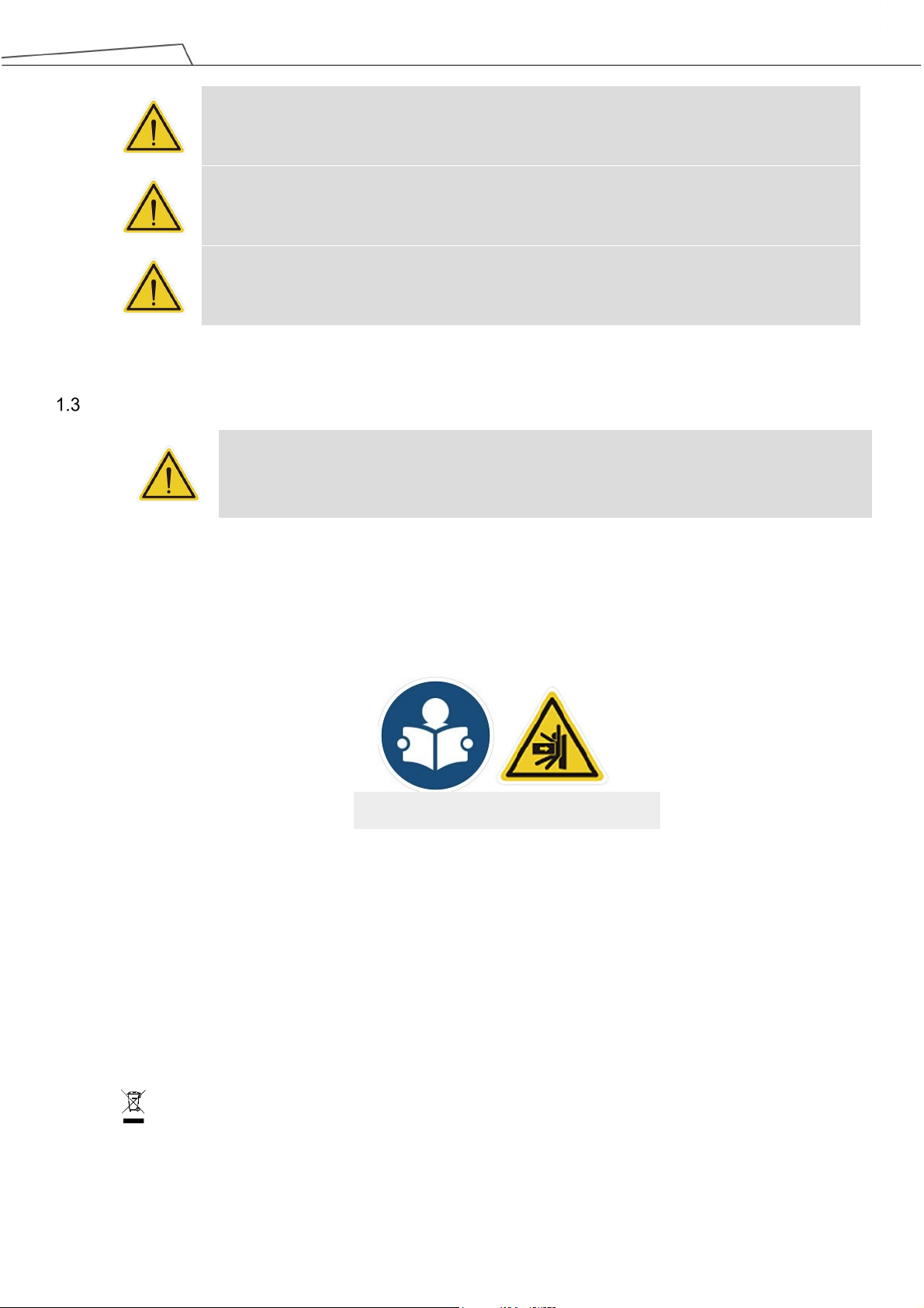
Landmark is a 0.2 cm thick and 5x5 cm square plastic plate as shown in the figure below. By
capturing and recognizing Landmark's black and white borders and central graphic features
through TM Robot's EIH camera, the robot can create the base system in the center of the
Landmark's black and white border. Note that the accuracy of landmark positioning is not
sufficient for identification and alignment purpose. In principle, Landmark is not designed for
users to have the robot directly go to individual points or execute motions after creating a base
system. Instead, it is an alignment tool to lead the robot toward a valid visual point. Users should
use the TM Robot visual positioning function to identify and locate the object in the last step to get
the best results.
Landmark generates a base system with six degrees of freedom, and the data in the RX, RY, and
Z directions are not easy to obtain accurately with EIH 2D vision (i.e. whether the camera plane is
parallel to the object and how long is the distance between the camera plane and the object).
Landmark can enhance the positioning ability of the 2D vision along these axes. Despite the fact
that Landmark is able to get the data of the X, Y, and RZ direction, chances are users may fail to
place or attach Landmark precisely in the operating environment, it is not recommended to use
the data directly for positioning. Due to the fact that these three degrees of freedom compensate
the positioning of the base data in EIH 2D vision, users should use both methods. As a regular
approach, users should use Landmark to have the robot guide its relative relationship between
the peripherals or the RX, RY, and the Z axes. That is to say, using the positioning of Landmark
on the three axes to ensure the visual points recorded in the Landmark base system after
updating with the landmark base system of the visual point camera posture, are able to return
back to the state of parallel with workpiece features (RX, RY) and to the correct distance to
workpiece features (Z). Users can then use this positioning as the basis for a subsequent 2D
vision job, and use each of the TMvision 2D functions to align the remaining axial directions of X,
Y and RZ. Even if the relative position between base of robot and the Landmark changes, users
can reuse the points and the motions recorded in the landmark base system from the former
project by having the robot shoot the Landmark again.
When planning a project, users may place Landmark in the target task environment to create a
TM Robot vision job and perform subsequent motions with the base system. Shooting the
Landmark again in later operations will have the robot reset to the original base system
automatically, i.e. to change alignment of robot according to site conditions without being confined
to a fixed alignment.
Software Manual TMvision Software version:1.82 14
Page 15
Landmark base system.
Figure 1: Landmark
NOTE:
The farther away the Landmark is from the camera the less accurate the
alignment will be. The tradeoff is that a bigger field of view tends to capture
changes of relative alignment between the robot and the Landmark. A shorter
distance between the camera and Landmark has the advantage of better
alignment accuracy but at the cost of a smaller field of view and Landmark's
easily falling outside the file of view. Users are advised to edit two vision jobs:
one nearer and the other farther, when using Landmark. The farther one is
aimed to quickly detect the Landmark in a workspace to create the first base
system. Then, pull the robot close while orienting the RX, RY, and RZ angles of
the second visual points (set these axes in the original base system orthogonal)
to zero and keep them as close as possible, e.g. camera and Landmark 10cm
apart from each other. Shoot the same Landmark to get a more accurate
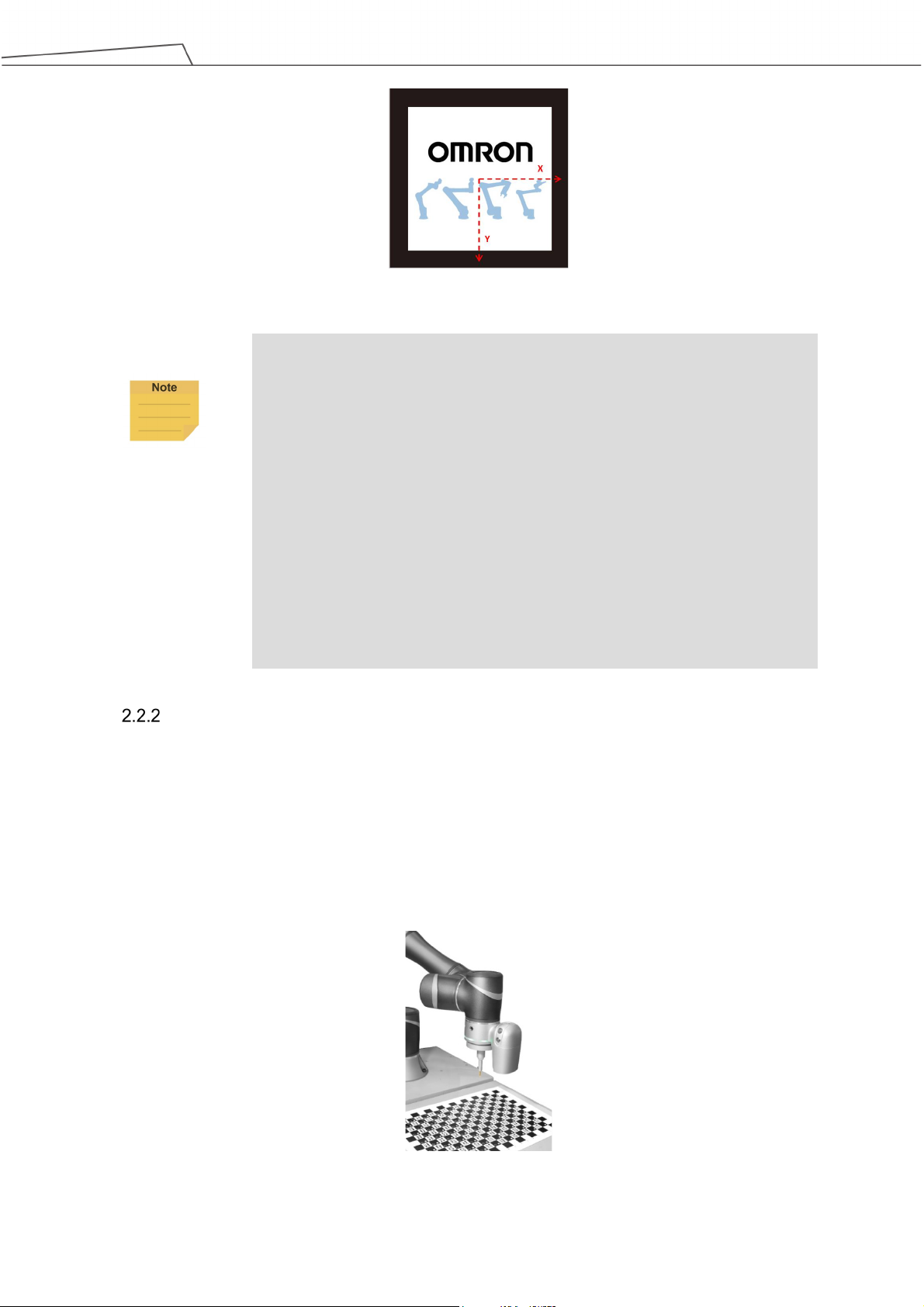
Fixed Positioning
The fixed positioning function is designed with a pre-set object placement area and pre-set height
for vision jobs. Users can create a workspace with the TM calibration plate. When using the TM
calibration plate for fixed-point alignment, the relative height of the camera and the work plane is
also defined. When using fixed-point alignment to establish a workspace, users must ensure that
the absolute height of camera and object is equal to the workspace created by the TM calibration
plate.
Software Manual TMvision Software version:1.82 15
Figure 2: Fixed Positioning
Page 16

Name
Function
change made after adjustment jobs ended.
adjustment.
Servoing
The servoing function is for users to define the object features. In each servoing process,
TMvision automatically sets the robot position based on the defined object to return the relative
position of the camera and object.
Object-based Calibration
The principle of object-based calibration is basically teaching as servoing and ending as
fixed-point positioning. First, run the tilt correction with the calibration plate to define the visual
servoing workspace with the actual workpiece and convert to the fixed point positioning with
calculations. Since the servo calibration is used only when defining the workspace for the first
time, the robot will place the workpiece at the four corners of the camera’s field of view to create
the workspace with four movements and make the fixed-point positioning calculation with the
workspace accordingly. This takes advantage of the fixed positioning's speed for positioning and
the servoing without the calibration plate. For the object calibration, the features of the object
should not be too big to fit in the field of view during the servo calibration.
Camera List
The list of cameras on the left side of TMvision shows the cameras in use and their status. Right-click
any listed camera to pop up a window that lets users refresh the list of cameras or detect an external
camera.
Controller
To help users control the robot movements, TMvision provides the controller interface for users to move
the robot to the appropriate positions and edit vision jobs.
Camera Kit
The camera kit is used to adjust camera imaging, including the following settings:
Camera Parameter
Setting
Focus / Aperture To assist adjusting focus and aperture of an external camera. It provides visual tools for
Software Manual TMvision Software version:1.82 16
Includes shutter and focus for the built-in camera and contrast and white balance for
extracted images. All modules feature auto once function. Click Save to validate
easy regulation. Users may read the scores of the current focus and aperture on the
left, which vary with change in focus and aperture with the external camera. The
calibration ends when the scores hit the Max line and stop rising even after more
Page 17

lower slides being farthest away from each other).
its current position.
3. Previous vision jobs built with 1.2M pixels will retain previous settings.
geometry does not allow for a calibration plate, users may replace the
Brightness Setting Includes illuminance visualization tool to enable users adjusting lighting tools for
optimized illumination distribution. The left side controls sensitivity of the visualization
tool. The two track bars in the settings indicate the upper and lower limits of the
visualization display. The brightness over the upper and lower limits are defaulted to
their limits for display. If the illuminance in the field of view is uniform, colors shown by
visualization tools may be close to each other in case of high sensitivity (upper and
Tilt-Correction Secure Landmark or calibration plate to the target plane as a calibration tool to enable
the robot's automatic adjustment to the tilt angle and vertical alignment of the camera
to target plane. Adjust camera parameter settings to ensure Landmark or the
calibration plate is detectable before running tilt-correction. Keep adequate clearance
around the robot, as in an automatic tilt-correction process the robot will move around
Table 3: Camera Kit Functions
NOTE:
1. The default resolution of the camera is 5M pixels, and so is the production
calibration. 5M pixels positioning is supported in Fixed Point and
Landmark.
2. If the robot came with TMflow 1.68 out of the box, once upgraded to
TMflow 1.72 or later, the default 5MP camera setting won't take effect.
Please contact service team to conduct 5MP calibration procedures to
enable this functionality.
Calibrate Workspace
Workspace calibration includes automatic and manual calibration to help users create workspaces for
fixed-point vision jobs. Workspace calibration will generate the information of the workspace as well as
the VPoint. Refer to Expression Editor and Listen Node for details of VPoint.
Automatic Calibration
The automatic workspace calibration goes with four steps:
1. Tilt-Correction
2. Confirm Workspace
3. Calibrate Workspace
4. Save Results
NOTE:
Before starting calibration: Position the identification target in the center of
the field of view using the controller or manual handle. Place the camera
10 to 30 cm above the target. Determine the plane where the feature is
located before placing the calibration plate on the plane. If the workpiece
Software Manual TMvision Software version:1.82 17
Page 18

tilt-correction while calibrating a workspace with eye-in-hand.
Step 1.
Tilt-Correction:
perpendicular to the camera parallel to the camera’s focal plane.
Step 2.
Confirm Workspace:
VPoint.
Step 3.
Calibrate Workspace:
the robot.
Step 4.
Save Results:
file to access it in fixed vision jobs.
plane where the feature is located before placing the calibration plate on
workspace with an object of the proper height to place the calibration plate
at the same height as the identification feature.
Click Yes when the message to skip tilt-correction prompts to bypass
IMPORTANT:
Keep adequate clearance around the robot as in an automatic calibration
process the robot will move around the initial position.
Once set up, do not touch the calibration plate before starting the calibration process.
Correct tilt before workspace calibration to ensure the calibration plate is
Visually check tilt-correction. Click the icon in the flow chart to calibrate tilt again if
necessary. The position of the robot, at the start of the calibration process, is called
the initial position of the robot in this workspace. This process also defines the
Click Start to have the robot take pictures of the calibration plate with multiple angles
to calculate the relative position of the workspace created by the calibration plate to
Once the accuracy has been validated, save the calibration results in a workspace
Manual Calibration
The manual workspace calibration goes with four steps:
1. Confirm Workspace
2. Set TCP Setting
3. Calibrate Workspace
4. Save Results
NOTE:
Before starting calibration: Mount the required calibration tool on the robot
tool flange. Techman Robot recommends using the calibration pin set
Software Manual TMvision Software version:1.82 18
provided by Techman Robot as the calibration tool. Using TMflow (TCP
Setting), set the Z height of the calibration tool. Position the identification
target in the center of the field of view using the controller or manual
handle. Place the camera 10 to 30 cm above the target; determine the
Page 19
bypass tilt-correction while calibrating workspace with eye-in-hand.
Step 1.
The robot must be positioned at the initial position of the robot in this workspace.
Step 2.
Set the Z height, using TMflow (TCP Offset), for the calibration tool being used.
Step 3.
controller to manipulate the robot when performing this calibration.
Step 4.
workspace file to access it in fixed vision jobs.
Functions
Suitable for hand-eye relationship
changing the scope of extraction by the camera.
Text tool
Set the color, the offset, the size, the style, the prefix and the suffix of
the plane. If the workpiece geometry does not allow for a calibration plate,
users can replace the workspace with an object of the proper height to
place the calibration plate at the same height as the identification feature.
Simply click Yes when the message to skip tilt-correction prompts to
IMPORTANT:
Once set up, do not move the calibration plate until the completion of the
calibration process.
Confirm Workspace:
Set TCP Setting:
Calibrate workspace: Point the calibration tool to the calibration plate grid shown on
the screen. When being prompted. Click Next. Repeat this step five times. Use the
Save Results: Once the accuracy has been validated, save the calibration results in a
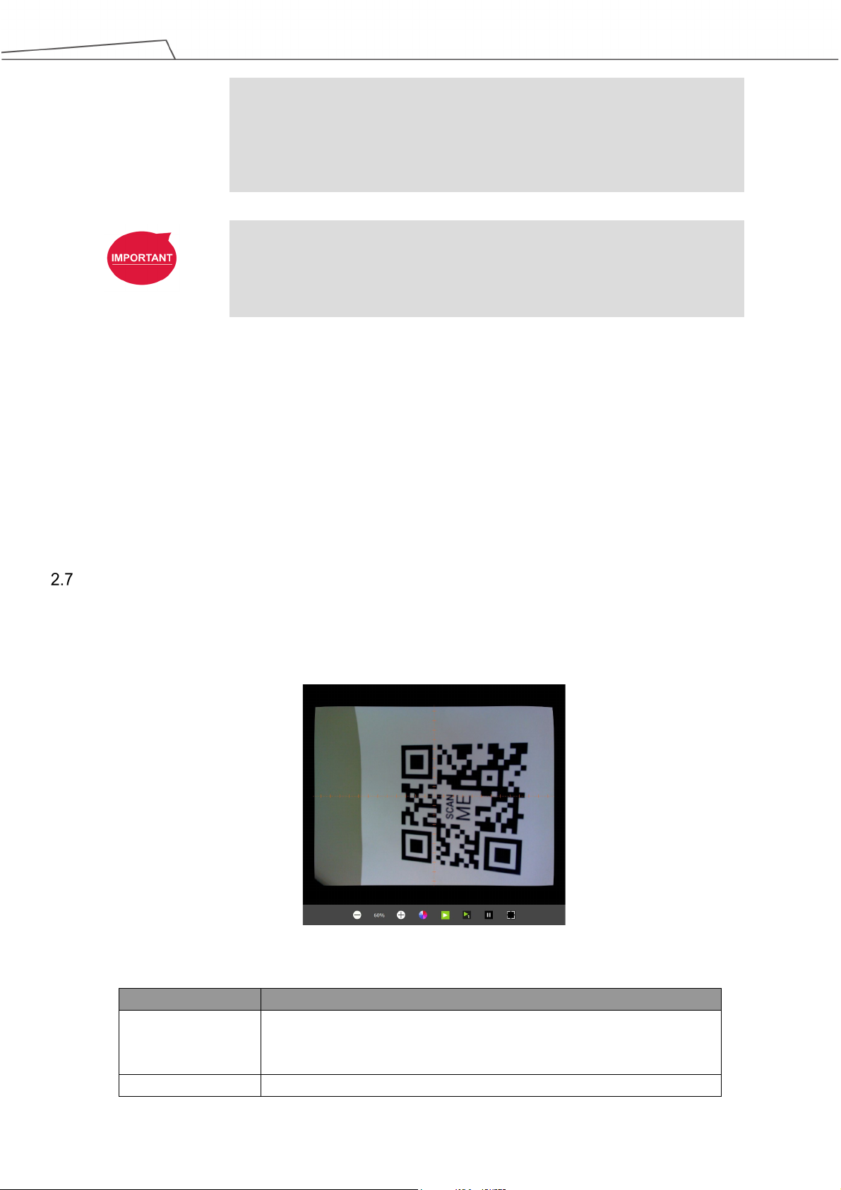
Live Video
Live Video provides a live camera image with functions at the bottom (from left to right): zoom out,
display ratio, zoom in, text tool, play, play once, pause, and grid
Figure 3: Live Video
Zoom out
Zoom in
Software Manual TMvision Software version:1.82 19
The Eye-in-hand / eye-to-hand function is designed to change display
ratio of the camera. This zooms in and out image displayed without
Page 20
the text and the objects on the screen.
when pressing the extract button.
Grid
Turn on grid at the center of the live video to help composition.
Play
Play Once
Pause
Set up extract mode (default = continuous extract) for users
convenience to capture current image shown on camera; pause extract:
to freeze image and stop capturing; extract once: to get current image
Table 4: Live Video Functions
NOTE:
Users can move the mouse cursor anywhere on the screen to view the
coordinates and the RGB values of the pixel in the live video.
Task Designer
TMvision provides users with a means of editing visual work, see Chapter 3 Task Designer for details.
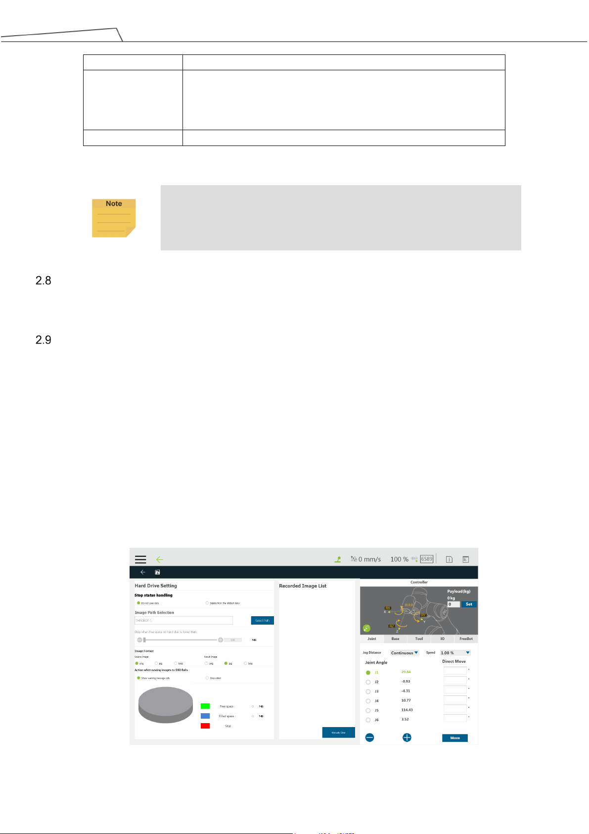
Hard Drive Setting
Hard Drive setting provides users with the ability to manage photo storage space and requires the
TM SSD (sold separately) to save source images or result images for analysis. Images can be saved in
png, jpg, or bmp. The Source Image is saved as png by default, the Result Image as jpg. The pie
chart in the bottom left displays used space, available space, and reserved space. Users may check
from Do not save data or Delete from the oldest data in Stop status handling. Click Select Path to
assign the path to store files, and drag the slider to configure the size reserved for the free space. Also,
users may check Show warning message only or Stop robot for the Action when saving images to
SSD fails. Show warning message only will display the warning message in the log of TMflow while
Stop robot makes the robot stops for the saving error.
Figure 4: Hard Drive Setting
Software Manual TMvision Software version:1.82 20
Page 21

NOTE:
It is favored to set the SSD reserved free space to 30% of the SSD total storage
space.
Software Manual TMvision Software version:1.82 21
Page 22
3. Task Designer
Overview
TMvision contains the following task designer functions: Visual Servoing, Fixed Point, AOI-only, Vision
IO, Landmark Alignment, Object-based Calibration, and Smart-Pick. Users can select the required
applications according to their needs and execute jobs with diversified visual algorithm.
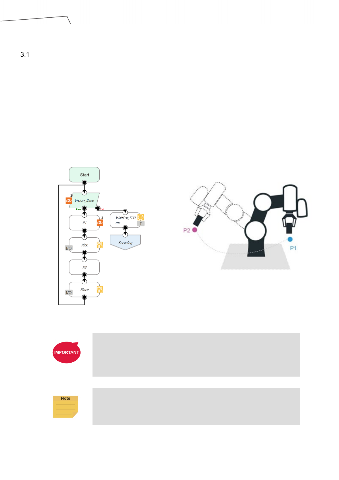
In addition to Vision IO and AOI-only identification, other applications can use the Find function to
position the base system to establish the relationship between the robot motion and the visual
components. As shown in the figure below, record point P1 on vision base system 2 and create relative
relationship with the object to access object visually.
Figure 5: The Flow of Pick and Place
IMPORTANT:
When using a vision base system, select the current base system shown at the
top right of TMflow as the vision base system.
NOTE:
In case of invalid selection, re-record the base system with the "Re-record on
another base “ in the Point Manager.
Software Manual TMvision Software version:1.82 22
Page 23
relationship
Eye-to-Hand
✓
object position
the robot position
Eye-to-Hand
Eye-to-Hand
Alignment
Landmark position
Calibration
object position
Smart-Pick
Eye-in-Hand
Select Application
Select the TMvision Task Designer in the work list and choose appropriate application according to
intended use. Basic categories are as follows:
Applications
Fixed Eye-in-Hand /
Servoing
AOI-only Eye-in-Hand /
Vision IO Eye-in-Hand /
Landmark
Object-based
Suitable for hand-eye
Eye-in-Hand
Eye-in-Hand
Eye-in-Hand × Create base system based on
Workspace Base system output
Create base system based on
× Create base system based on
× ×
× ×
×
Create base system based on
Table 5: Select Applications
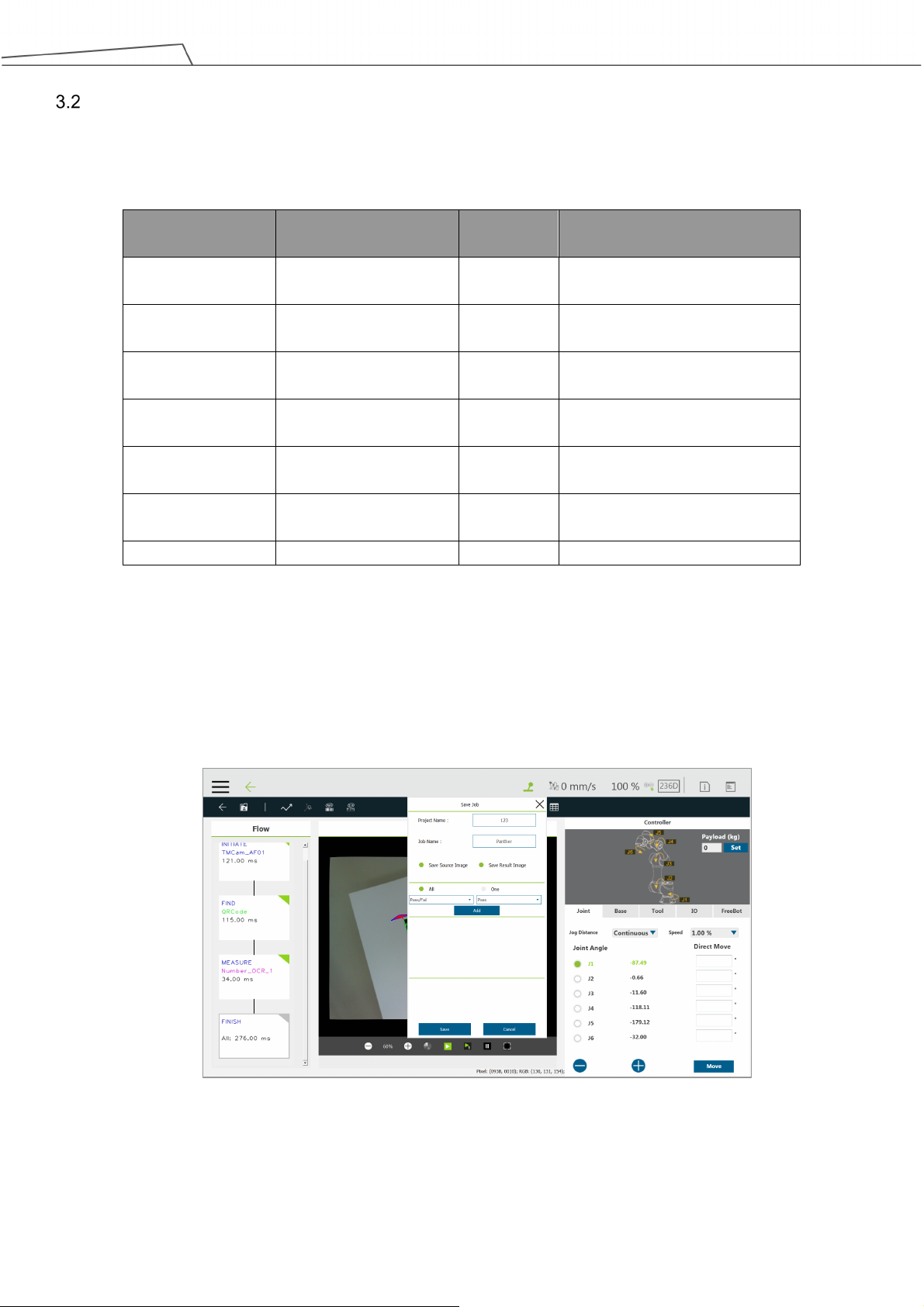
Users can save vision images by setting criteria based on the results of object detections, recognitions,
and measurements. Images available to save include the original image (source image) and the last
image taken (result image).
Figure 6: Save Vision Images Based on Results
Software Manual TMvision Software version:1.82 23
Page 24

Name
Function
Click Save to validate changes made.
image
at the current position.
Lighting
Control light source switch at end of the robot.
Light Intensity*
Use the slider to set the brightness level
position
position
Stabilization
self-adjust before taking pictures.
NOTE:
The name of the selected application will be put above the flow at the left as a
label.
Visual Servoing
Enter the TMvision Task Designer window and select Visual Servo to use this function. Visual
servoing is only suitable for eye-in-hand. Alignment is achieved by getting continuously closer to
the object's target coordinate on the image. The workspace does not need to be established. If
the target angle has wide variations, use a calibration board to conduct level calibration during the
initial alignment. The servoing time is determined by region of convergence and the robot
movement path. This can be applied to situations where the relationship between the camera,
workspace, and the robot can easily change due to changes in human action and the
environment. After the level is calibrated, select INITIATE on the left side of the Flow to make
basic parameter settings. Setting parameters are as follows:
Adjust camera
parameters
Switch to record
Start at initial
position
Move to the initial
Reset initial
Idle for Robot
*Available for HW 3.0 models or newer.
Includes shutter and focus for the built-in camera and contrast and white
balance for extracted images. All modules feature an auto once function.
Use the internal TM SSD images for identification.
Check this to return the robot to its initial position before visual
identification. Uncheck this and the robot will execute visual identification
Move the robot to the initial position
Reset initial position of the robot
Set the length of time manually or automatically to have the robot
After the basic parameters have been set, confirm that the image is clear and can be seen. Select
the Find function at the top and use the pattern matching function to match the pattern's shape
feature in the selected frame.
Once the matching patterns have been determined, TMvision will compare the image in the
Software Manual TMvision Software version:1.82 24
Table 6: Visual Servoing Settings
Page 25

pattern.
Name
Function
position
to be a match.
set value of the angle, it is judged to be a match.
compensation
value of the found object.
plane
exceeds this value.
this value.
current field of view against the one in storage to compute shape features and identify differences
between them as well as give scores for similarity determination. Users may set up appropriate
thresholds to determine whether the two images are of the same object.
NOTE:
TMvision provides an easy feature editing function. If patterns selected contain
unnecessary features users can click Edit pattern icon to modify features of the
Exit and return to the flow chart once completed. Users may set servoing target when there is at
least one Find function in the in visual flow chart.
Figure 7: Visual Servoing
Parameters of the teaching page are described below:
Move to the initial
Distance (pixels) When features distances between the current object and the target
Angle When features angles between current and target object fall below the
Depth
Radius in X-Y
Distance in ± depth Stop the robot movement when the vertical movement distance exceeds
Move the robot to the initial position
model are less than or fall below the set value of the distance, it is judged
Whether or not to perform depth compensation based on the Scaling
Stop the robot movement when the horizontal movement distance
Software Manual TMvision Software version:1.82 25
Page 26

(2) Locate target at image center
successful servoing.
the Depth, and the length of Timeout.
the project goes to the flow where the condition is fail.
node.
Name
Function
Save to validate changes made.
image
position.
position
Reset workspace
Reset the robot's workspace.
Lighting
Toggle camera light on or off.
Light Intensity*
Use the slider to set the brightness level.
Stabilization
before taking pictures.
Set servoing target Determine servo target position by clicking the button and options below.
(1) Use current position
Start Servoing Click and hold to run the servoing process. Only save the results after
Stop Criterion Use the sliders to configure the stop criteria of the Distance, the Angle,
Timeout (second) Defaults to 45 seconds. Available from 10 ~ 45 seconds. Once triggered,
Moving Range Use the sliders to configure the ranges of the limitations in the Radius,
the Distance, and the Rotation angle of the camera. If the camera goes
beyond the range, the system will take the fail route and leave the Vision
Table 7: Parameters of the Teaching
After configuring the servoing target setting, click Start Servoing and press the (+) button on the
robot stick to have TM Robot begin servoing the visual screen. Save the results once TMvision
prompts servoing completed successfully.
Fixed Point
Enter the TMvision Task Designer window and select Fixed Point to use this function. The fixed
point function is designed for EIH and ETH for the robot to calculate and position objects with
absolute coordinates by creating workspaces. Accuracy varies with that of workspace calibration.
Refer to 2.2 Vision Base System Positioning Mode for details on creating workspaces. After
choosing the workspace, use INITIATE in Flow on the left side to set basic parameters. Setting
parameters are shown below:
Adjust camera
parameters
Switch to record
Start at initial
position
Includes shutter and focus for the built-in camera and contrast and white
balance for extracted images. All modules feature an auto once function. Click
Use the internal TM SSD images for identification.
Check this to return the robot to its initial position before visual identification.
Uncheck this and the robot will execute visual identification at the current
Move to the initial
Idle for Robot
Software Manual TMvision Software version:1.82 26
Move the robot to the initial position.
Set the length of time manually or automatically to have the robot self-adjust
Page 27

node.
Snap-n-go Improve efficiency by concurrently taking snaps and keeping the flow going to
save time for non-vision tasks that follow. After the image has been captured,
the system will go to the next node and keep the image processing in the
background from the flow. Note that when the processes after the Vision node
require the result from the Vision node and the background image processing is
still running, there will be conditions and returns as follows:
If the next node requires the parameters of the result, such as the
Boolean variables Done and Pass generated by the Vision job, users will
have to edit an If node for the system to determine how to proceed.
If the next node is also a Vision node which includes a Vision base point
or a Vision job, the flow will not continue until it is done with the last Vision
*Available for HW 3.0 models or newer.
Table 8: Fixed Point Settings
After configuring the basic camera parameters, select the Find function at the top and select the
pattern matching function as shown below. TMvision will use the framed shaped feature to find its
alignment on the image and build the visual base on the object.
Figure 8: Fixed Point
Once the matching patterns have been determined, TMvision will compare the image in the
current field of view against the one in storage to compute shape features and identify differences
as well as give scores for matching. Users may set up thresholds to determine whether the two
images are the same object.
AOI-only
Enter the TMvision Task Designer and select AOI-only to use this function. The AOI-only
identification is applicable to EIH or ETH to read Barcode and QR code, Color Classifier, and
Software Manual TMvision Software version:1.82 27
Page 28

Name
Function
Save to validate changes.
image
position.
position
Reset workspace
Reset the robot's workspace.
Lighting
Control the light source switch at end of the robot.
Light Intensity*
Use the slider to set the brightness level.
Stabilization
before taking pictures.
node.
String Match without workspace and base system output. To identify a barcode, make sure there
is only one clear and readable barcode in the framed region and use INITIATE on the left side of
Flow to set basic parameters. The parameters are shown as below:
Adjust camera
parameters
Switch to record
Start at initial
position
Move to the initial
Idle for Robot
Snap-n-go Improve efficiency by concurrently taking snaps and keeping the flow going to
Includes shutter and focus for the built-in camera and contrast and white
balance for extracted images. All modules feature an auto once function. Click
Use the internal TM SSD images for identification.
Check this to return the robot to its initial position before visual identification.
Uncheck this and the robot will execute visual identification at the current
Move the robot to the initial position.
Set the length of time manually or automatically to have the robot self-adjust
save time for non-vision tasks that follow. After the image has been captured,
the system will go to the next node and keep the image processing in the
background from the flow. Note that when the tasks after the Vision node
require the result from the Vision node and the background image processing is
still running, there will be conditions and returns as follows:
If the next node requires the parameters of the result, such as the
Boolean variables Done and Pass generated by the Vision job, users will
have to edit an If node for the system to determine how to proceed.
If the next node is also a Vision node which includes a Vision base point
or a Vision job, the flow will not continue until it is done with the last Vision
*Available for HW 3.0 models or newer.
After setting the basic parameters, choose the pattern matching function in the Find function at
the top to proceed with matching. The identification is for a specific spot o n ly, not for the entire
field of view. Users can use the Find function to adjust the search range to find the object feature.
Once the object feature is found, the object's barcode can be accurately identified. The barcode
identification will output the identification result. Use the Display node to confirm the accuracy of
the barcode.
Vision IO
Software Manual TMvision Software version:1.82 28
Table 9: AOI-only Settings
Page 29

Name
Function
Position
Rest Initial Position
Rese the initial position of the robot.
limit, the process exits through the Fail path.
triggered event occurs.
Threshold
Trigger event sensitivity: The lower the threshold, the more sensitive.
Enter the TMvision Task Designer window and select Vision IO to use this function. When an
obvious change occurs in the picture, the difference before and after the change can be used to
determine whether a change has occurred to the Sensing Window. The Vision IO module views
the camera as an IO module, and continuously monitors a specific area in the screen. When the
area shows significant change in content, a trigger signal is sent to TMflow.
Startup method:
Task Designer → Vision IO
In comparison to the previous vision tasks in the flow, when selecting Vision IO at startup, users
can set up in the prompt as shown in the left of the figure below.
Figure 9: Vision IO
Move to Initial
TimeOut Set the time waiting for Vision IO. If the IO is not activated within the time
Set sensing
window
Move the robot to the initial position
Set a region in the live video as an area to monitor. After the setting is
completed, if the level of variations goes over the threshold, it means that
Table 10: Vision IO Settings
Landmark Alignment
Enter the TMvision Task Designer window to select and use the Landmark Alignment function.
Users may run this function with the official Landmark. This is meant to build subsequent teaching
points on the base system added by the Landmark.
Software Manual TMvision Software version:1.82 29
Page 30

Name
Function
validate changes.
image
position.
position
Figure 10: Landmark Alignment (1/2)
For points that were recorded on the robot base, users must teach all points again if the relative
relationship between the robot and the object has changed. If the vision base system was created
through Landmark and the aligning point is based on the previous vision base system, if the
relative relationship between the robot and the object has changed, it only takes the vision node
execution to update the Landmark vision base system.
Figure 11: Landmark Alignment (2/2)
The Landmark Alignment parameter settings are as follows.
Adjust camera
parameters
Switch to record
Start at initial
position
Move to the initial
Software Manual TMvision Software version:1.82 30
Includes shutter and focus for the built-in camera and contrast and white balance
for extracted images. All modules feature an Auto once function. Click Save to
Use the internal TM SSD images for identification.
Check this to return the robot to its initial position before visual identification.
Uncheck this and the robot will execute visual identification at the current
Move the robot to the initial position
Page 31

Reset workspace
Reset the robot's workspace
Lighting
Toggle camera light on or off.
Light Intensity
Use the slider to set the brightness level
Stabilization
before taking pictures.
node.
Idle for Robot
Snap-n-go Improve efficiency by concurrently taking snaps and keeping the flow going to
*Available for HW 3.0 models or newer.
Set the length of time manually or automatically to have the robot self-adjust
save time for non-vision tasks that will follow. After the image has been captured,
the system will go to the next node and keep the image processing in the
background from the flow. Note that when the processes after the Vision node
require the result from the Vision node and the background image processing is
still running there will be conditions and returns as below.
If the next node requires the parameters of the result such as the Boolean
variables Done and Pass generated by the Vision job, users will have to
edit an If node for the system to determine how to proceed.
If the next node is also a Vision node which includes a Vision base point or
a Vision job, the flow will not continue until it is done with the last Vision
Table 11: The Fixed Settings
NOTE:
Users can add Enhance, Identify, and Measure modules to the Landmark
Alignment flows for the use of flexibility.
Object-based Calibration
Object-based calibration is applicable to EIH only, which employs the difference in the robot
servoing movement to calculate relative relationship between the object and the robot without
workspace creation. If the positioning target angle has large variations, users must run the
horizontal calibration with the calibration plate before determining the initial position. This function
delivers high precision for objects with simpler shapes by building the fixed-point base system
directly on the object to reduce the errors on the height measurements made with the calibration
plate. When the horizontal calibration is completed, click Find function to select Pattern
Matching(Shape) apart from Pattern Matching(Image), Blob Finder, Anchor, and Fiducial Mark
Matching for TMvision to frame the shape.
Once the matching patterns have been determined, TMvision will compare the image in the
current field of view against the one in storage to compute shape features and identify differences
between them as well as give scores for similarity determination. Users can set thresholds to
determine if the two images are the same object. Exit and return to the flow chart once completed.
Once edited and there is at least one Find module in the visual flow chart, click Calibration to
Software Manual TMvision Software version:1.82 31
Page 32

Name
Function
position
robot movement.
robot movement.
after the robot successfully completes these actions.
perform object-based calibration.
Figure 12: Object-Based Calibration
Move to the initial
Radius in X-Y plane When the horizontal moving distance exceeds this value, stop the
Distance in ± depth When the vertical moving distance exceeds this value, stop the
Start calibration Click and hold to the + button on the robot stick to servo the object.
Move the robot to the initial position.
The robot will move four times to place object at each of the four
corners of image field to complete the action. Only save the file
Table 12: Object-Based Calibration Settings
Smart-Pick
Smart-Pick lowers the threshold of using TMvision by adopting the Vision button to perform a step
by step and simple-to-use vision job teaching process, and users can use Landmark to achieve a
fixed point vision job without the calibration plate. Smart-Pick applies to the stack of boxes, pick
and place with trays (low precision requirements), and applications with extra compensations
(force sensor, gripper, or object restricted position.) Using Smart-Pick for applications with 1~2 ㎜
accuracy is recommended.
Software Manual TMvision Software version:1.82 32
Page 33

in the last saved setting will be cleared.
NOTE:
To switch the Vision button at the end of the robot to Smart-Pick, go to TMflow >
☰ > Setting > End Button > Vision Button and check Smart-Pick.
Users can start using Smart-Pick by navigating to Task Designer > Please select an
application to start and click the Smart-Pick icon or press the Vision button at the of the robot if
switched to Smart-Pick.
Steps to use Smart-Pick
1.
Put Landmark in the vision of the robot. Move the robot if necessary. Click NEXT to
automatically adjust shutter, white balance, and focus based on the current location.
2.
If the automatic adjustment does not fit, click Change Settings to adjust manually.
3.
Push the + button on the robot stick to perform tilt-correction. Click NEXT when done and
setting the landmark base as the work platform of the object.
4.
Click Camera Settings if necessary and capture the image of the background without the
object. Click NEXT.
5. Capture the image of the object with the background.
6.
Adjust Region of Interest parameters for the best outcome. Click Select ROI to scale
ROI down.
7.
Adjust the matching parameters or use Edit Pattern to edit the feature of the object. Set
Search Range of the object location, rotation, and scale in the image.
8.
Click Save to save the job. The default job name goes by SmartPick_ with a sequence
number. Users can use the Vision button as Done, Save, and Yes in this step.
To apply extra functions such as enhance, users can lick Transform Into a General
Vision Job to save the job without the Smart-Pick feature. Once transformed, there is no
way to revert the Smart-Pick feature.
NOTE:
The next time users open the save Smart-Pick job, the system will prompt
users to transform into a general vision job or not.
Once opened as the Smart-Pick job, the system will prompt users to select
which step to start with. Whichever step users take, the system will prompt
users to return to the initial position with the robot stick and the after steps
Function list
The TM Robot Vision Designer provides three module functions: Enhance, Find and Identify.
Software Manual TMvision Software version:1.82 33
Page 34

Enhance settings
Function description
Image source
Switch among source image modules
Contrast
Adjust contrast. Adjust in the negative direction for a negative image.
Enhance
Enhance provides multiple functions to enhance image features and improve successful project
identification in special application environments.
Function module
Contrast Enhancement
Color Plane
Extraction
Smoothing
Thresholding
Morphology
Function description
Adjust image contrast.
Obtain specific colors (such as red, blue, or green) or saturation.
Filter out noise and increase the image's smoothness.
Transform a raw image into a black and white one.
Erode, dilate, patch, or open the image.
Flip
Flip the image.
Table 13: Function List – Enhance
Contrast Enhancement
Adjust image brightness and contrast to enhance the contrast between object and
background to improve accuracy of object detection.
When the contrast between the region of interest (ROI) against the background is poor, users
may enhance it with this module to improve the success rate of object comparison. Users are
advised to maximize differences between brightness of foreground and background by
adjusting the contrast value. Then adjust the gamma value to brighten the bright area and
dim the dark area.
Software Manual TMvision Software version:1.82 34
Page 35

Brightness
Adjust brightness
Gamma
Adjust image gamma value
Reset
Reset parameters
Color plane
Select specific color plane for adjustment.
Lookup Table
Conversion curve for the input and output
Histogram
Image's histogram
Enhance settings
Function description
Image source
Switch among source image modules
- Value
Histogram
Image's histogram
Table 14: Function List – Enhance (Contrast Enhancement)
Color Plane Extraction
Users can extract a specific color plane from an image or convert the color plane from RGB
space to HSV space. With the emphasis on the different color planes of the objects and the
backgrounds, users can choose the appropriate color plane to increase the contrast between
the object and the background and improve the detection accuracy.
The object search module basically operates in a grayscale space. Imported color images are
converted into grayscale. Users may use this module to convert images into color space with
the best foreground/background difference to improve object identification.
Color plane The color plane will evaluate:
- Gray
- Red
- Green
- Blue
- Hue
- Saturation
Table 15: Function List – Enhance (Color Plane Extraction)
Software Manual TMvision Software version:1.82 35
Page 36

Enhance settings
Function description
Image source
Switch between source image modules
- Median filter
greater region where the median filter will adjust width parameters only.
Enhance settings
Function description
Image source
Switch between source image modules
Raw image
Green
Saturation
Gray Red
Blue Hue
Val u e
Table 16: Function List – Enhance (Color Plane Extraction – Color Plane)
Smoothing
Filter type Select filter type:
- Mean Filter
- Gaussian filter
Mask size Regarding mask size: larger mask size results in a smoothing effect in a
Table 17: Function List – Enhance (Smoothing)
Thresholding
Set the gray value of pixels larger than the upper threshold to gray value upper limit and
pixels smaller than the lower threshold to gray value lower limit, and simplify the color scale of
the image.
Software Manual TMvision Software version:1.82 36
Page 37

To Zero (Inverted): If higher than threshold, set as zero.
Enhance settings
Function description
Image source
Switch between source image modules.
extract the edge area.
Ellipse
Element size
The larger the element size the greater the calculation range.
Iteration
Number of repeated operations
Enhance settings
Function description
Image source
Choose the source image
Flip Direction
Vertical, horizontal.
Threshold type Binary: If higher than threshold, set as white. If lower, then set as black.
Binary (Inverted): Set to black if higher than threshold. Otherwise, set to
white.
Truncated: If higher than threshold, set equal to threshold.
To Zero: If lower than threshold, set as zero.
Table 18: Function List – Enhance (Thresholding)
Morphology
Morphology computing is often applied to binarized images, applying closing or opening
effects to the current image for noise removal or connecting broken foreground objects.
Operation type Dilation: Expand the white area.
Erosion: Erode white areas.
Opening: Erode the white area before dilating it to open connected weak
sides or remove broken fractures.
Closing: Dilate the white area before eroding it to patch up broken faces
or voids.
Gradient: Subtract the image after erosion from the image after dilation to
Structuring element Rectangle
Flip
This function can be used to flip the image.
Cross
Table 19: Function List – Enhance (Morphology)
Table 20: Function List – Enhance (Flip)
Software Manual TMvision Software version:1.82 37
Page 38

Function module
Function description
Output (floating point)
anchor point.
home (upper left).
home (upper left).
label.
Find
Pattern Matching (Shape)
Pattern
Matching
(Image)
Blob Finder
Anchor
Fiducial Mark
Matching
External
Detection
Locate an object in the image based on
its geometrical features.
Locate an object in the image based on
its pixel value distribution features.
Locate an object by the color difference
between the object and the
background.
Change home coordinates of object
detection by manually adjusting the
Use the two obvious features on the
object for matching.
Use a remote computing platform with
the protocol of HTTP for object
detecting and positioning.
Relative to coordinates X, Y
and rotation angle R of image
home (upper left).
Relative to coordinates X, Y
and rotation angle R of image
home (upper left).
Relative to coordinates X, Y
and rotation angle R of image
home (upper left).
Relative to coordinates X, Y
and rotation angle R of image
Relative to coordinates X, Y
and rotation angle R of image
Relative to coordinates X, Y,
rotation angle R of image
home (upper left) and object
Table 21: Function List – Find
Flow
The left side of the vision programming flow chart shows the computing flow of vision tasks.
The highlighted bold frame indicates the process now in focus. The green frame indicates the
process functioned successfully, and the orange frame indicates the process functioned
unsuccessfully.
IMPORTANT:
If any of the processes in a flow are orange, the flow cannot be saved.
Pattern Matching(Shape)
The function uses the geometrical shape of the object as its pattern model and matches it to
the input image to find the object in the image. It supports variations due to object rotation
Software Manual TMvision Software version:1.82 38
and dimension. It is best for objects with rigid profiles.
Page 39

Name
Function description
Pattern Selection
After selection, this image will pop up. Users can select the object in the image.
Step 5: Press Next to exit the Smart Pattern Learner.
Pattern editor
Click and the edit window pops up to edit shape feature of the object.
Set search range
Set the location, size, and rotation of the range to search.
in detection errors.
minimum setting.
Objects
according to the setting of this field.
Directional Edge
Select whether the shape edge is directional.
more misjudgments. Frequently used values fall between 0.75 and 0.85.
Pattern
Check Directional Edge
Uncheck Directional Edge
Smart Pattern
Learner
Number of Pyramid
Layers
Minimum Score Object can be identified only when the score of the detection is higher than the
Max. Num. of
Sorted by: When the maximum number of objects is greater than 1, the outputs will be sorted
To create fast visual extract tasks with process learning the pattern model.
Step 1: Add object search module (shape), click "Smart Pattern Learner".
Step 2: Shoot background.
Step 3: To shoot a workpiece, press Next to identify the target object once it gets
located.
Step 4: Adjust the threshold, internal distance, and external distance.
The number of processing iterations to perform on the image. More layers reduces
processing time, but for images with a lot of detail, the detail may get lost, resulting
The maximum number of objects that can be detected in the image.
Table 22: Function List – Find (Patten Matching (Shape))
IMPORTANT:
Search range: Set rotation angle smaller for symmetrical objects , e.g.
rectangles (-90~90), squares (-45~45), and circles (0~1).
The number of Pyramid Layers are directly linked with speed of pattern
matching. The algorithm matches layers from top down. As an additional
layer is added, the pixel resolution is halved, but the search speed is up.
The frequently used value for the layers falls between 3 and 5. Users may
set up according to characteristics of pattern edge feature. Fewer layers
will preserve more feature details, and more layers result in less
processing time.
Smaller minimum scores reduces omissions from judgments at the cost of
Software Manual TMvision Software version:1.82 39
Page 40
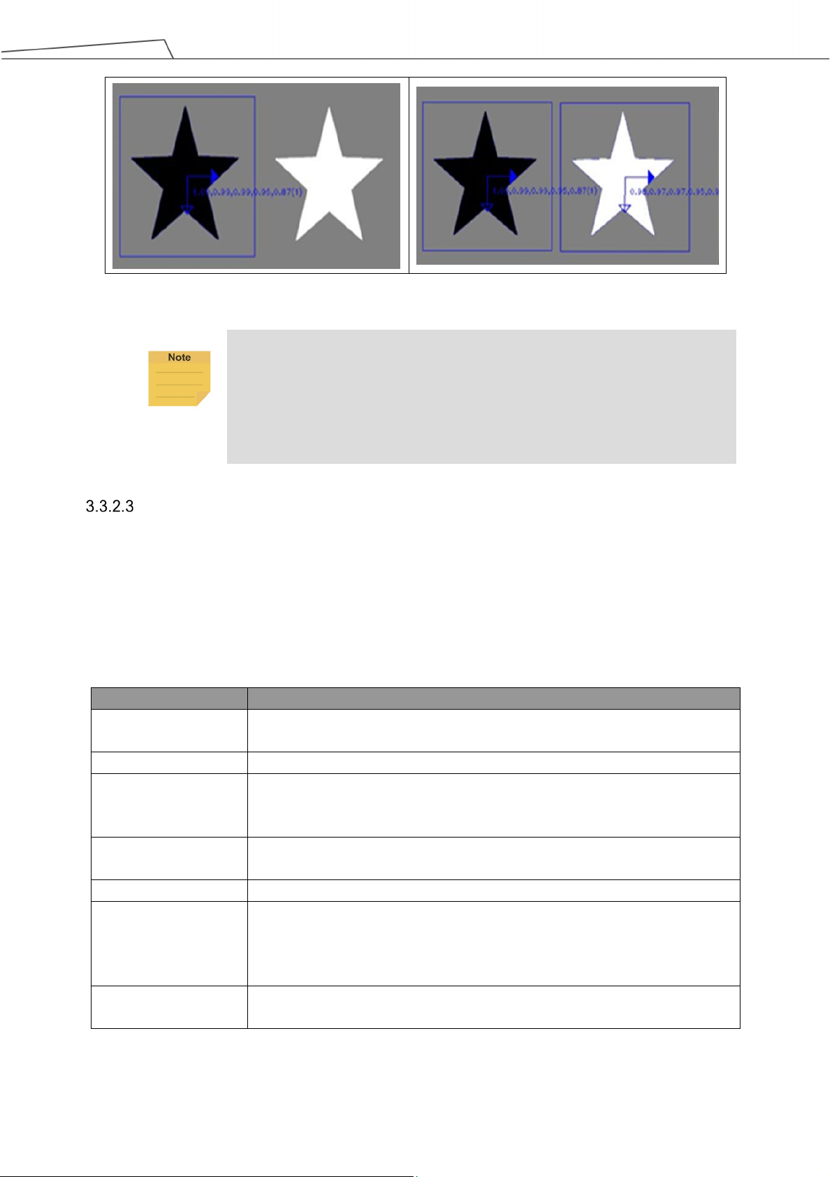
the left side gets detected). Otherwise, both stars will be detected.
Name
Function description
image.
Set search range
Set the location, size, and rotation of the range to search.
lost, resulting in detection errors.
system will identify this as the object.
Max. Num. of Objects
The maximum number of objects that can be detected in the image.
shadow changing ability is stronger.
be sorted according to the setting in this column.
Table 23: Function List –Find (Patten Matching (Shape))
NOTE:
The pattern matching algorithm determines matching of objects based on
strength and directions of object edges. Edge direction refers to whether the
edge is from light to dark or from dark to light. When directional edge is checked,
the direction of the pattern's edges will influence the identification result (star on
Pattern Matching (Image)
This function uses the image of the target object itself as its pattern model and matches it to
the input image to position the object in the image. It supports variations due to object shift
and rotation. Differing from shape pattern matching, this function does not support dimension
changes and may take a long time to compute. It may be employed when the workpiece lacks
visible features or has fuzzy edges.
Pattern Selection After selection, this image will pop up. Users can select the object in the
Num. of Pyramid
Layers
Min. Score If the score of the detection result is higher than this minimum score, the
The number of processing iterations to perform on the image. More layers
reduces processing time, but for images with a lot of detail, the detail may get
Similarity Metric Users can pick the most appropriate measuring method from among the
"Correlation Coefficient" or "Absolute Difference" methods. The former has a
slower speed, but is tolerant of ambient light differences, and the light and
Sorted by: When the maximum number of objects is greater than 1, the output result will
Table 24: Function List – Find (Patten Matching (Image))
Software Manual TMvision Software version:1.82 40
Page 41

more misjudgments. Frequently used values fall between 0.75 and 0.85.
Name
Function description
Set search range
Set effective detection range
Color plane
Choose color space to use
Extract color
Click and enclose color of ROI on image.
Plane
this area will be discarded.
Max. Num. of Objects
The maximum number of objects that can be detected in the image.
sorted according to the setting of this field.
IMPORTANT:
Search range: Set rotation angle smaller for symmetrical objects , e.g.
rectangles (-90~90), squares (-45~45), and circles (0~1).
The number of Pyramid Layers are directly linked with speed of pattern
matching. The algorithm matches layers from top down. As an additional
layer is added, the pixel resolution is halved, but the search speed is up.
The frequently used value for the layers falls between 3 and 5. Users may
set up according to characteristics of pattern edge feature. Fewer layers
will preserve more feature details, and more layers will reduce processing
time.
Smaller minimum scores reduces omissions from judgments at the cost of
Blob Finder
Differing from detecting objects of fixed geometry by pattern matching, objects without fixed
geometry should use this function for detection.
Red, green, blue
Area size To set up area of foreground scope: Objects with foreground pixels outside of
Sorted by: When the maximum number of objects is greater than 1, the outputs will be
Distribution range of ROI color
Table 25: Function List – Find (Blob Finder)
Anchor
The anchor function sets the initial position and the orientation of the object base system.
Users can find objects with a Find module, and the default base system of the objects is
marked with blue arrows, which is for users to anchor a point at the end of the flow. Setting
the initial position to the top left vertex and parallel to the black frame will orient the vision
base with the anchor.
Software Manual TMvision Software version:1.82 41
Page 42

Name
Function description
Manual adjustment
Manually drag the anchor point to the target position.
X direction shift (pixels)
Move the anchor in the X direction.
Y direction shift (pixels)
Move the anchor in the Y direction.
Rotation
Rotate the anchor about its initial position.
Name
Function description
Set fiducial marks
Set two anchor points on the image in sequence
Set search range
Set search range of the two anchor points on the image in sequence
Threshold
Set matching threshold
is stronger.
Figure 13: Anchor
NOTE:
The hollow arrow denotes the X direction, and the solid arrow denotes the Y
direction.
Table 26: Function List – Find (Anchor)
Fiducial Mark Matching
The Fiducial Mark Matching function is designed to detect and position the two positioning
points on PCBs. It is fast and reliable. However, this function has a smaller search range and
lower success rate when the objects zoomed or rotated. For example, this function is suitable
for PCB operation, which features little shift in feeding position and requires quick and
accurate positioning.
Similarity Metric Users can pick the most appropriate measuring method from "Correlation
Coefficient" or "Absolute Difference". The former has a slower speed, but is
tolerant of ambient light differences, and the light and shadow changing ability
Table 27: Function List – Find (Fiducial Mark Matching)
Software Manual TMvision Software version:1.82 42
Page 43

One Shot Get All
This function creates multiple sets of independent processes for one visual task by taking one
shot to output multiple-objects and multiple-sets of identification results to save a lot of
repetitive computing time as only one shot is required.
This feature supports fixed-point positioning, AOI identification only object search modules,
and ETH "Pick'n Place" module.
Step 1:
Step 2:
Step 3:
Step 4:
Create a visual object search process module such as Find > Pattern Matching
(Shape).
Select the INITIATE process, but do not open it.
Add another visual object search process module to make the One Shot Get All
menu appear.
Select Parallel to add independent search processes in parallel to each other, or
select Cascade to add process modules one after the other.
Figure 14: One Shot Get All (1/4)
Software Manual TMvision Software version:1.82 43
Page 44

Figure 15: One Shot Get All (2/4)
Step 5:
Save the vision job.
Figure 16: One Shot Get All (3/4)
The vision job generates N sets of the vision base after finished, they generate, and each set
of the vision base comes with variables var_MAX and var_IDX as the maximum number of
the object searching and the current base index respectively.
By taking one single shot to capture multiple objects, objects can be picked and placed in
sequence with batches. As shown below, after passing the vision node, the individual
maximum number of the object searching and the individual current base index will be reset.
As one job finishes, the base index variable var_IDX proceeds the action +1 with the SET
node to denote a job completed and compares with var_MAX in the IF node. If var_IDX
equals var_MAX, it means the job is done for that object and will search for the next object in
Software Manual TMvision Software version:1.82 44
Page 45
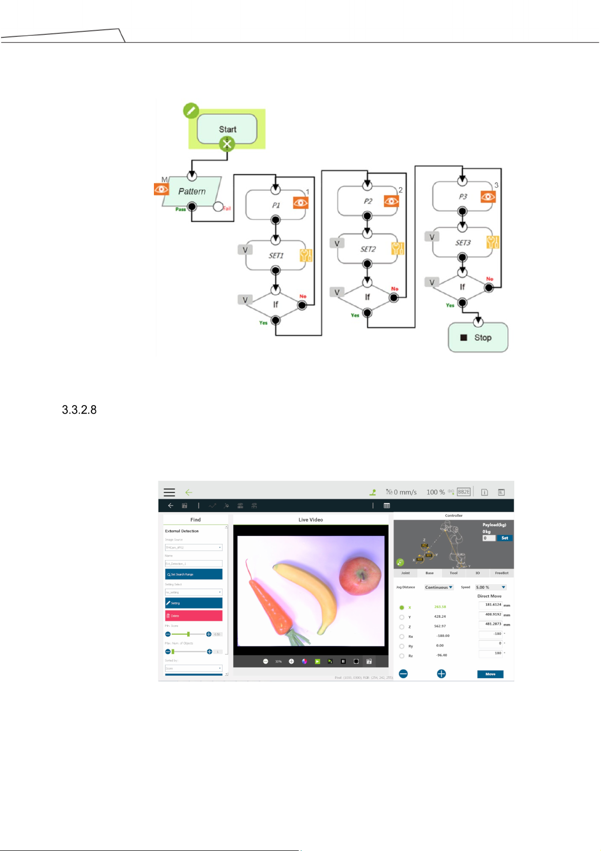
order until all jobs are done.
Figure 17: One Shot Get All (4/4)
External Detection
External Detection uses a remote computing platform with the protocol of HTTP for object
detecting and positioning.
Figure 18: External Detection (1/2)
Use the dropdown below Image Source to select the source of the image. In the field below
Name, input the name for the detection. Use Set Search Range button to set regions of
object searching in the image. Use the dropdown below Setting Select to select configured
Software Manual TMvision Software version:1.82 45
Page 46

2. URL = http://127.0.0.1:80/detection?model_id=test
HTTP parameters. The default goes without any selected model. Use Setting button to
modify parameters for the respective model. Parameters in HTTP Setting and Inference
POST: Get, URL, Post Key, Value, jpg/png, Timeout(
㎳), Setting name. A warning
message prompts if overwriting HTTP Setting with the same Setting name. No identical
individual Setting name of HTTP Setting is allowed in one TM Robot.
Figure 19: External Detection (2/2)
NOTE:
As a network communication protocol, HTTP works only when the connection is
established. External Classification use POST cmd on every classification to
send pictures to the HTTP server by the configured URL. The HTTP server
inspects the pictures by breaking up the relevant key-values and returns the
result in the JSON format packets to TM Robot.
# Protocol Define of Find - AI_Detection
1. Image size : decided by TM vision image source
2. Image format : jpg or png
3. box_cx: center x, true location on source image, float
4. box_cy: center y, true location on source image, float
5. box_h: height, int
6. box_w: width, int
7. label: object name show on TMvision, string
8. rotation: clockwise, float
9. score: between 0.00 and 1.00, float
10. message:
if "success", our detection module output annotations
else output error message
# Detection Example
1. Sample image = "Image.jpg"
Software Manual TMvision Software version:1.82 46
Page 47

}
3. curl example = curl -X POST -F file=@"C:/Image.jpg"
"http://127.0.0.1:80/detection?model_id=test"
4. JSON response
{
"annotations" : [
{
"box_cx" : 150,
"box_cy" : 150,
"box_h" : 100,
"box_w" : 100,
"label" : "apple",
"rotation" : -45,
"score" : 0.96
},
{
"box_cx" : 550,
"box_cy" : 550,
"box_h" : 100,
"box_w" : 100,
"label" : "car",
"rotation" : 0,
"score" : 1.0
},
{
"box_cx" : 350,
"box_cy" : 350,
"box_h" : 150,
"box_w" : 150,
"label" : "mobilephone",
"rotation" : 135,
"score" : 0.88
}
],
"message" : "success"
Drag the slider below Min. Score to remove objects below the minimum score. Drag the
slider below Max. Num. of Objects to set the maximum available number of object to display.
Use the dropdown below Sorted by to select the sorting method of object priorities.
The sorting method goes by Score, Left to Right, Right to Left, Top to Bottom, Bottom to
Top, Nearest to Image Center, Nearest to Top-Left, Nearest to Top-Right, Nearest to
Bottom-Left, and Nearest to Bottom-Right. Use Save Image button to save the image in
the region to inspect. The image is saved as yyyy-MM-dd-HH-mm-ss_zzz.png in the path as
[drive_letter]:\project_name\job_name\yyyy-MM-dd\object_name\.
Software Manual TMvision Software version:1.82 47
Page 48

Function module
Function description
Output (floating point)
code.
failed read.
and cases output.
width (pixel)
height (pixel)
EAN-8
2 8 EAN-13
2 8 UPC-A
2
8
When the vision job of TMflow comes to an end, the module External Detection outputs the
position and the label of the detected object.
Identify
This function provides two basic functions: Barcode and color identification with string output
once successfully identified. Users may compile processes in TMflow with output of results.
Barcode / QR code
Color Classifier
String Match
External
Classification
Read the barcode, the 2D
DataMatrix, or the QR
Content of the barcode or QR, for a
successful read. “” (empty string) for a
Color classifier
Compare strings Matching results customized by users
Use a remote computing
platform with the protocol
of HTTP for inspections
Users set the characters for the string
and for the training.
The image classification result string
Table 28: Function List – Identify
Barcode / QR Code
This function supports the decoding of 1-D barcode, QR code and 2-D DataMatrix. The user
frame selects the barcode region in the Set Barcode Range for the identification. For
barcodes in white symbols on black background: Users may select "Enhance" (and set Alpha
value to -1) to invert the image before identifying it.
IMPORTANT:
Make sure there is only one clear barcode in the area for reading.
Barcode / QR code supported:
1D Barcode Type Minimum bar
Software Manual TMvision Software version:1.82 48
Minimum bar
Page 49
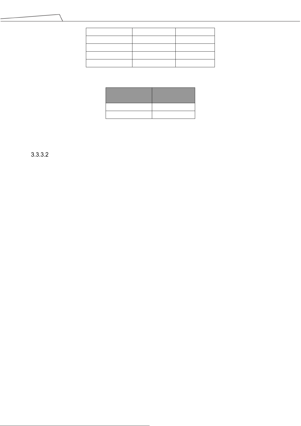
UPC-E
2 8 CODE 128
2 2 CODE 39
2 2 CODE 93
2
2
Interleaved 2 of 5
2
2
size (pixel)
QR code
4 x 4
Data Matrix
6 x 6
Table 29: Function List – Identify (Supported Barcodes)
2D Barcode Type Minimum block
Table 30: Function List – Identify (Supported QR codes)
Color Classifier
This function assists users in dealing with a color identification. Users are required to set up
color classification area and select the color feature area for identification before clicking
Next to initiate the training process. In addition, users are required to place patterns of
different colors as prompted and name each color during the training process. Once trained
successfully, the TMvision can classify color of the object to its most suitable category. Click
Parameter Adjustment to set RGB and HSV parameters for each color in the list with the
sliders, and click OK to update parameters or Reset to cancel. Users can also check
Uncertain Class and set the Threshold for applications such as the assembly line with
objects of unknown color to make the color classifier pick up the color of interest and leave
other color as null. Uncertain Class works by matching the list of color with color
classification area to get a matching score. If the score is below the threshold, it outputs
uncertain in a string.
Software Manual TMvision Software version:1.82 49
Page 50

Figure 20: Color Classifier
String Match
This function compares strings from sources in the flow or with a fixed string set by users, and
generates the matching customizable results for further applications. In String 1, users can
select the source in the Connected To dropdown, or check Fixed String and fill a desired
string in the field below. Repeat the same process for String 2. Finally, customize the
messages with color to output as the results for Match or Mismatch.
Figure 21: String Match
External Classification
External Classification uses a remote computing platform with the protocol of HTTP for
inspections and cases output.
Software Manual TMvision Software version:1.82 50
Page 51

Figure 22: External Classification (1/2)
Use the dropdown below Image Source to select the source of the image. In the field below
Name, input the name for the classification. Use Set ROI region button to set regions of
searching, rotation, and scaling positions. Use the dropdown below Setting Select to select
configured HTTP parameters. The default goes without any selected model and outputs
no_model string while the project is running. Use Setting button to modify parameters for the
respective model. Parameters in HTTP Setting and Inference POST: Get, URL, Post Key,
Value, jpg/png, Timeout(
㎳), Setting name. A warning message prompts if overwriting
HTTP Setting with the same Setting name. No identical individual Setting name of HTTP
Setting is allowed in one TM Robot.
Figure 23: External Classification (1/2)
Software Manual TMvision Software version:1.82 51
Page 52

}
NOTE:
As a network communication protocol, HTTP works only when the connection is
established. External Classification use POST cmd on every classification to
send pictures to the HTTP server by the configured URL. The HTTP server
inspects the pictures by breaking up the relevant key-values and returns the
result in the JSON format packets to TM Robot.
# Protocol Define of Identify – External Classification
1. Image size : arbitrary
2. Image format : jpg or png
3. If message is "success", our classification module output result string,
otherwise output server error code string
4. Give inference score between 0.0000 ~ 1.0000
# External Classification Example
1. Sample image = "Image.jpg"
2. URL = http://127.0.0.1:80/classify?model_name=test
3. curl example = curl -X POST -F file=@"c:/Image.jpg"
"http://127.0.0.1:80/classify?model_name=test"
4. JSON response
{
"message": "success",
"result": "ok",
"score": 0.9876
Drag the slider below Score Threshold to set the threshold of classification. Use Save
Image button to save the image in the region to inspect. The image is saved as
yyyy-MM-dd-HH-mm-ss_zzz.png in the path as
[drive_letter]:\project_name\job_name\yyyy-MM-dd\object_name\.
When the vision job of TMflow comes to an end, the module External Classification outputs
the result of the image classification in a string.
Software Manual TMvision Software version:1.82 52
Page 53

Brand
Type
Specification
Remark
Rolling Shutter
Global Shutter
Global Shutter
Rolling Shutter
Rolling Shutter
Rolling Shutter
Rolling Shutter
4. TM External Camera
Overview
TM external camera is the TMvision's licensed software module, which requires the purchase. It can
support connections for up to two external cameras at the same time. TMvision also provides a support
tool to help users adjust the external camera's various parameters. External cameras can be used for all
TMvision tasks except servoing. There is also an alignment compensation function that is divided into
the eye-to-hand or upward-looking camera according to application. The following introduces various
camera types and related settings.
WARNING:
Due to the hardware resource restrictions, when using HW 1.0 models or HW 2.0 models, the
system is incapable of connecting 2 or more cameras with 5M pixels or more.
Types of Camera Supported
acA2500-14gc/gm
acA 2500-20gc/gm
acA 2440-20gc/gm
BASLER
acA 3800-10gc/gm
acA 4024-8gc/gm
BFLY-PGE-50A2C-CS(color)
Flir
BFLY-PGE-50A2M (Gray)
GigE (14 fps at 5 MP)
GigE (14 fps at 5 MP)
GigE (23 fps at 5 MP)
GigE (10 fps at 10
MP)
GigE (8 fps at 12.2
MP)
GigE (13fps at 5 MP)
GigE (13fps at 5 MP)
HW 3.0 only
HW 3.0 only
External Camera Installation Procedure
Step 1:
Step 2:
Software Manual TMvision Software version:1.82 53
Table 31: Types of Camera Supported
Enter TM Flow -> System setting -> Network setting.
Select "Static IP" and enter the following settings. Click Confirm.
Set IP address: use either 192.168.61.101 or 192.168.88.102
Page 54

subnet mask: 255.255.255.0
Step 3:
Enter the Setting page -> Visual setting -> left side "Camera list" on a blank spot, click
the right mouse button -> select "Detect GigE Camera".
Step 4:
Wait for the camera detection to refresh -> left side "Camera list" on a blank spot, click
the right mouse button -> select "Refresh Camera List".
Step 5:
GigE camera complete and the camera appears on the camera list. The camera will
show "Unknown" at this time.
Step 6:
Once the user completes the steps in the implementation section 4.4 Calibrating the
External Camera, the external camera function will be activated.
IMPORTANT:
Ensure the camera is connected to the control box's network outlet and the signal light is on.
Calibrating the External Camera
Once the external camera has been connected, the user needs to calibrate the camera and choose
between the eye-to-hand or upward-looking mode for the camera. This establishes the corresponding
position between the external camera and the eye-in-hand camera, as well as calibrates the camera's
internal parameters.
ETH Camera Calibration
Manual Calibration: Automatic Calibration:
Step 1:
Select the "Unknown" external camera at the left side camera list to establish a new
vision job, and then select “calibrate camera”.
When the menu presents, select
"Eye-to-Hand" and then choose
automatic calibration.
Step 2:
When the menu presents, select
"Eye-to-Hand" and then choose manual
calibration.
Calibrate the eye-to-hand camera's internal parameters. Move the calibration plate
into the camera's field of view. Click "Next Step" and repeat this step 15 times with
different calibration plate positions and angles. Click "Next Step" when done.
Step 3:
Step 4:
Click “Next Step” to build a workspace.
Set and select the tool center of the
Calibration Set. Click "Next Step" when
done.
Calibrate workspace. Move the
eye-in-hand camera to within the visual
range of the calibration plate. Calibrate
the eye-in-hand and eye-to-hand
Software Manual TMvision Software version:1.82 54
Page 55

camera's external parameters and
relative relationship. Click "Next Step"
when done.
Step 5:
Calibrate the eye-in-hand and
Save the calibration result.
eye-to-hand camera's external
parameters and relative relationship. A
red dot will appear at the top of the
calibration plate screen. Point to the red
dot on the calibration plate using the
TCP. Repeat this step and select "Next
Step" to complete the calibration.
Step 6:
Save the calibration result.
Upward-looking Camera Calibration
Manual Calibration: Automatic Calibration:
Step 1:
Select the "Unknown" external camera on the left side camera list to establish a
new vision job, and the then select “calibrate camera”.
Step 2:
Step 3:
When the menu presents, select
"Upward-looking" and choose manual
calibration.
Calibrate the upward-looking camera's
internal parameters. Fix the calibration
plate to the end of the robot and move
the calibration plate into the field of view
of the camera. Click "Next Step" and
repeat this step 15 times with different
calibration plate positions and angles.
Click "Next Step" when done.
Move the calibration plate to a height
appropriate for identifying the object.
Click "Next Step" when done to start the
automatic workspace setting.
When the menu presents, select
"Upward-looking" and choose automatic
calibration.
Fix the calibration plate to the end of the
robot. Choose the tool center and set
the initial position. Click "Next Step"
when done.
Calibrate the upward-looking camera's
internal parameters. Click "Next Step"
when done.
Step 4:
Step 5:
Calibrate workspace. Click "Next Step" when done.
Save the calibration result.
Software Manual TMvision Software version:1.82 55
Page 56

to click the intersection at the top of the calibration plate.
IMPORTANT:
Before performing manual calibration, use the calibration set to calibrate the appropriate
tool center. Make sure the tolerance is less than 0.3mm, and then use the calibration set
Lens Setting
Lens selection has a large impact on image quality. Generally, the lens center is closer to the real image,
but the areas around the center are usually not clear enough or bright enough and can be easily
distorted. We recommend that when the user chooses a lens, the user should adjust the focus and the
aperture based on the size of the workpiece.
Focus / Aperture
The camera kit provides focus and aperture adjustment functions. This can help users adjust an
externally connected industrial camera's aperture and focus to the most appropriate position and
obtain the clearest image quality. Focus and aperture adjustment page's "Focus Flow" displays
the camera's focus status. "Aperture Flow" displays the aperture adjustment status. The X-axis
represents the time and the Y-axis represents the score that changes with time. The red line
represents the previous highest value. The user can adjust the focus adjustment ring and the
aperture adjustment ring on the camera lens to see the values on the corresponding flow change.
The user should adjust the aperture and the focus to make the value (black line) reach the
maximum value (red line). This is the most appropriate aperture and focus.
Figure 24: Focus/Aperture
Eye-to-Hand
Not only can TMvision integrate internal vision, but also match to the supported external cameras to
feed the obtained information back to the robot. This operation allows the robot motion to synchronize
Software Manual TMvision Software version:1.82 56
Page 57

with camera shooting and decreases the flow cycle. An illustration of the eye-to-hand camera
configuration is as shown below.
Figure 25: Eye-to-Hand
Pick'n Place
Pick'n Place, as one of the most common uses of Eye-to-Hand, is the fixed position application
for the eye-to-hand function. This function uses the establishment of a workspace so that the
robot can use the absolute coordinates to calculate and position objects. Its precision is
determined by the calibration accuracy of the workspace. For details on fixed positioning and
building a workspace, refer to 3.2.2 Fixed and 2.2 Vision Base System Positioning Mode. In
addition, the external camera can be used to complete more tasks. For example, TMvision can
use the external camera to implement "Fixed function" or use the combination of external camera
and internal camera to achieve other applications.
AOI-only / Vision IO
The eye-to-hand module supports the AOI-only with Vision IO function. For details, refer to 3.2.3
AOI-only and 3.2.4 Vision IO.
Upward-Looking
The TMvision upward-looking function uses the relationship between the base and the robot obtained by
placing the calibration plate on the object. Command is given to the robot based on the identified feature
to move to the object's position of the first upward-looking teaching. This corrects the position deviation
of the object caused by claw or suction nozzle instability. In addition, the upward-looking module
supports AOI-only and Vision IO function. The following is an illustration of the upward-looking camera's
setting.
Software Manual TMvision Software version:1.82 57
Page 58

position is to the object plane the more accurate it is.
Figure 26: Upward-Looking
Alignment Compensation
The alignment compensation function allows the user to use the upward-looking camera to
position the workpiece and to establish a vision tool center. This function compensates the
workpiece's X and Y-axis coordinates' deviation and rotation angles' deviation for each item
picked. This means that even if the user caused a workpiece deviation during the pick'n place, the
robot can still accurately place the workpiece at the correct position.
Step 1:
Step 2:
Establish a new vision job and choose the upward-looking module.
Select alignment compensation, move to the initial position, and establish object
detection.
Step 3:
Step 4:
Save job to automatically form a vision tool center.
Now the alignment compensation function can be used. Use this vision tool center to
establish points. Even if the workpiece grabbing position deviates when moving to
the point position, the function can still compensate the workpiece position and
accurately move to the correct position.
AOI-only / Vision IO
The upward-looking module supports the AOI-only and Vision IO function. For details, refer to
3.2.3 AOI-only and 3.2.4 Vision IO.
IMPORTANT:
When calibrating or conducting alignment compensation, pay attention to
the stability of the calibration plate or object. If the object or calibration
plate moves significantly when the robot moves the object, this object is
not suitable for alignment compensation and the object grabbing method
needs to be improved.
Set the tool center position before calibration. The closer the tool center
Software Manual TMvision Software version:1.82 58
Page 59

5. TM OCR
Overview
TM OCR is the TMvision's licensed software module, which requires purchase. It provides that users
with a simple operating interface to set OCR jobs. OCR is divided into OCR and Number OCR.
Measurement, identification, and TM OCR function can be used through the menu at the top of the
TMvision setting interface. TM OCR supports the eye-in-hand camera and external cameras. If an
external camera (eye-to-hand, upward-looking) needs to be matched to conduct OCR identification,
activation of the external camera is required. For the activation and the use of the external camera, refer
to Chapter 4. TM External Camera.
OCR
Figure 27: OCR
Support Content
OCR function can output the identification results in strings.
OCR supports nine common fonts and their bold format (Regular 400, Bold 700) shown in
the table below.
Font Type
serif ,
sans-serif , ,
monospaced , , ,
Table 32: OCR Supported Fonts
OCR supports 94 printable characters ranging from ASCII codes 21
to 7E
hex
including letters,
hex
Software Manual TMvision Software version:1.82 59
Page 60

text/white background
Menu
e other similar
characters.
Width
Height
Spacing
Overlap
overlap ratio exceeds this
value.
Ratio
than this value.
digits, punctuation marks, and a few miscellaneous symbols.
OCR identification area is a single line. Characters go from left to right in a straight line or a
curve. A single line contains 32 characters at max.
Parameter Setting Interface
Name Function description
Image source
Name
Set OCR Region
Segmentation
Font Selection
White text/black
background or black
Candidate Characters
Choose image source.
Name the task.
Set the location, size, and rotation of the range to search.
Adjust character segmentation parameters.
Choose the font to be identified.
Choose White text/black background or black text/white background.
Output according to the selected character list. Eliminat
Table 33: OCR Parameter Settings
Set OCR Region
The region can be divided into rectangles or curves. Drag the frame over the desired region
to adjust the size of the region. Click the rotate symbol on the edge of the frame to rotate the
region. The arrow on the edge of the frame represents the direction the characters are written.
When using the curved region, single click the arrow to switch the direction of the arrow in
correspondence to the concave or convex curved characters.
Segmentation
Name Function description
Bounding Rect
Bounding Rect
Min Char
Char Fragment
Min Char Aspect
Tilt-angle
Character width must be within this range.
Character height must be within this range.
Characters are combined when character spacing is lower than this value.
Characters are combined when the character
Character height divided by width. Characters are segmented if it is lower
Angle correction. Turn tilted characters upright.
Table 34: OCR Parameter Settings – Segmentation
Software Manual TMvision Software version:1.82 60
Page 61

Character Selection
TMvision provides four trained types of characters for users to choose from, Universal (94
characters), Universal_Digit (numeral 0~9), Universal_UpperCase (Latin alphabet (A~Z)),
Universal_LoweCase (Latin alphabet (a~z))
Candidate Characters Menu
Candidate characters can be set in the candidate character menu. Characters in black
indicate candidate characters, and characters in gray indicate eliminated characters. The
identification result does not output eliminated characters. Users can use @ (all), $ (numeral),
# (upper case), * (lower case), or % (symbol) to list and combine possible candidate character
combinations. The first symbol in the combination represents the candidate character of the
first character, the second symbol represents the candidate character of the second character,
and so on.
Number OCR
Figure 28: Number OCR
Support Content
Number OCR function can output identification result in floating-point numbers.
Font Type
serif ,
sans-serif , ,
monospaced , , ,
Table 35: Number OCR Supported Fonts
Software Manual TMvision Software version:1.82 61
Page 62

Name
Function description
text/white background
Function description
Width
Height
Overlap
Characters are combined when the character overlap ratio exceeds this
value.
Supports Seven-segment-display.
Supports 12 characters, including numbers (0~9), - , and . to determine positive, negative,
the numbers, and the decimal point.
Identification region is a single line. Characters go from left to right in a straight line or a
curve. The output numeral range is valid for 7 digits as the single-precision floating-point
format.
Parameter Setting Interface
Image source Choose image source.
Name Name the task.
Set OCR Region Set the location, size, and rotation of the range to search.
Segmentation Adjust character segmentation parameters.
Font Selection Choose the font of the region to be identified.
White text/black
background or black
Choose white text/black background or black text/white background.
Table 36: Number OCR Parameter Settings
Setting Identification Region
The identification region can be divided into rectangles or curves. Drag the frame over the
desired region to adjust the size of the identification region. Click the rotate symbol on the
edge of the frame to rotate the identification region. The arrow on the edge of the frame
represents the direction the characters are written. When using the curved region, single click
the arrow to switch the direction of the arrow in correspondence to the concave or convex
curved characters.
Segmentation
Name
Bounding Rect
Bounding Rect
Min Char Spacing
Char Fragment
Software Manual TMvision Software version:1.82 62
Character width must be within this range.
Character height must be within this range.
Characters are overlapped when character spacing is lower than this value.
Page 63

Ratio
lower than this value.
Min Char Aspect
Character height divided by width. Characters are segmented their ratio is
Tilt-angle
Angle correction. Turn tilted characters upright.
Table 37: OCR Parameter Settings – Segmentation
Font Selection
The Number OCR provides two font models for the user to choose from, Number and
seven-segment-display. While Number font includes the OCR fonts and seven-segment
display font model, seven-segment-display font adopts font Digital Counter 7 and font Ticking
Timebomb BB for reading only.
Software Manual TMvision Software version:1.82 63
Page 64

6. TM Identify & Measure
TM Identify & Measure is a TMvision licensed software module that requires purchase. In addition to
standard Color classifier and Barcode identification, licensed identify functions are: Pose Variation
(Shape), Pose Variation (Image), Specific Color Area Size, Subtract Reference Image, Line Burr, and
Circle Burr. Measurement Module functions are: Counting (Shape), Counting (Image), Counting (Blobs),
Counting (Edges), and Gauge.
Note:
Users can create up to 8 modules (Identify or Measure) for each vision job.
Identify
Traditional manual inspection can lead to errors caused by personnel fatigue or negligence. The
TMvision identification function can provide comprehensive improvement. The menu at the top of the
TMvision setting interface can be used to add identify functions to the vision flow. The following
describes the various functions in detail.
Function module Output (floating point)
Pose
Variation(Shape)
String. Output TMflow variation "OK" or "NG" according to conditions.
Pose
Variation(Image)
String. Output TMflow variation "OK" or "NG" according to conditions.
Specific Color
Area Size
String. Output TMflow variation "OK" or "NG" according to conditions.
Subtract
Reference
Image
String. Output TMflow variation "OK" or "NG" according to conditions.
Line Burr
String. Output TMflow variation "OK" or "NG" according to conditions.
Circle Burr
String. Output TMflow variation "OK" or "NG" according to conditions.
Software Manual TMvision Software version:1.82 64
Page 65
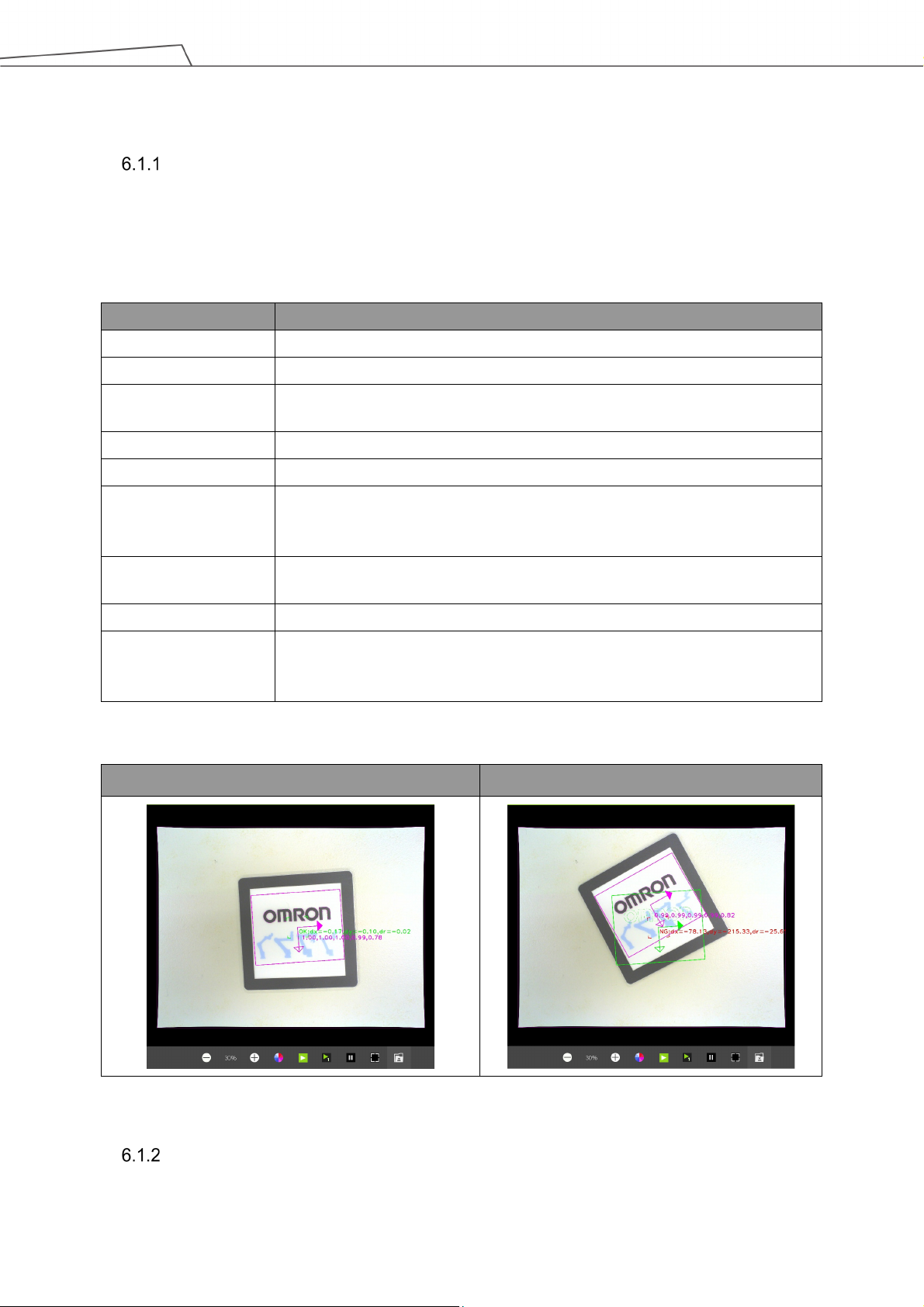
the image.
lost, resulting in detection errors.
than the minimum setting.
Pose's angle variation: Angle's allowable rotation deviation.
Table 38: Identification Functions
Pose Variation (Shape)
This module uses the object's shape feature to calculate variation and askewness to determine
whether the object's level of pose change is within the decision range. This can be used to
inspect whether the label position on the product has changed or is askew.
Name Function description
Image source Choose image source.
Name Name the task.
Pattern Selection After clicking, this image window will pop up. The user can select items from
Edit Pattern Click and the edit window pops up to edit shape features of the object.
Set search range Set the location, size, and rotation of the range to search.
Num. of Pyramid
Layers
Min. Score Object can be identified only when the score of the detection result is higher
Directional Edge Select whether the shape edge is directional.
Decision Pose's X-variation: X-direction's allowable shift deviation.
The number of processing iterations to perform on the image. More layers
reduces processing time, but for images with a lot of detail, the detail may get
Pose's Y-variation: Y-direction's allowable shift deviation.
Table 39: Pose Variation (Shape) Functions
OK NG
Table 40: Pose Variation (Shape) Examples
Pose Variation (Image)
This module uses the object's image feature to calculate variation and askewness to determine
Software Manual TMvision Software version:1.82 65
Page 66

whether the object's level of pose change is within the decision range.
the image.
lost, resulting in detection errors.
than the minimum setting.
capability.
Pose's angle variation: Angle's allowable rotation deviation.
Name Function description
Image source Choose image source.
Name Name the tas
Pattern Selection After clicking, this image window will pop up. The user can select items from
Edit Pattern Click and the edit window pops up to edit shape features of the object.
Set search range Set the location, size, and rotation of the range to search.
Num. of Pyramid
Layers
Min. Score Object can be identified only when the score of the detection result is higher
Similarity Metric The user can use the "Correlation Coefficient" or the "Absolute Difference" to
Decision Pose's X-variation: X-direction's allowable shift deviation.
The number of processing iterations to perform on the image. More layers
reduces processing time, but for images with a lot of detail, the detail may get
select the most appropriate measuring method. The former is slower, but it
can resist environmental lighting and has stronger light and shadow change
Pose's Y-variation: Y-direction's allowable shift deviation.
k.
Table 41: Pose Variation (Image) Functions
OK NG
Table 42: Pose Variation (Image) Example
Specific Color Area Size
This function uses the object's color area to determine whether the size of the area is within the
decision range.
Name Function description
Software Manual TMvision Software version:1.82 66
Page 67

detected on the image.
omitted
added to the decision.
region to be detected on the image.
reference image on this image.
Omitted
included in the decision.
Name Function description
Image source Choose image source.
Name Name the task.
Select ROI After clicking, this window will pop up. The user can select the region to be
Add region to be
Color plane Choose RGB or HSV color space.
Extract color After clicking, this image window will appear. The user can select the color
Red/Hue Adjust the color feature's red/hue value to be detected.
Blue/Saturation Adjust the color feature's blue/saturation value to be detected.
Green/Value Adjust the color feature's green/value to be detected.
Decision Area size: The total colored area in this range determined to be OK.
Click to set the region to be omitted. The area within the range will not be
Table 43: Specific Color Area Functions
This example detects whether the liquid capacity in the container reaches the standard.
OK NG
Table 44: Specific Color Area Size Example
Subtract Reference Image
This module uses the difference between the source image and the reference image to calculate
whether the number of defects and their sizes is acceptable.
Name Function description
Image source Choose image source.
Name Name the task.
Select ROI After clicking, this image window will pop up. The user can choose the
Add Region to be
Software Manual TMvision Software version:1.82 67
Clicking can set the region to be omitted. Defects within the range will not be
Page 68

will be included in the defect area.
matching.
the position and the angle are ±5 pixels and ±5°, respective l y.
The larger the element size the greater the calculation range.
detected on the image.
Intensity Threshold Only differences with the reference image's gray value larger than this value
Defect Area Size Only defect areas in this range will be included in the defect quantity.
Decision Defect quantity: Total defect quantity in this range is determined to be OK.
Bounding Box Select this function to show the defect position with a bounding box.
Deburring Remove the image edge or erroneous determination caused by pattern
Local Alignment Enhance stability of recognition in case the object is too small to detect by
correcting the position and the angular deviation. The compensate range of
Element Size Remove the burr calculation element size.
Table 45: Subtract Reference Image Functions
This example shows the detection of whether the product printing has defects.
Reference image Defect image Detection result image
Table 46: Subtract Reference Image Example
IMPORTANT:
When the "Find" module caused a position error, the burr on the edge will be
erroneously determined as damage. The user can select the deburring function.
Line Burr
This module uses the differences between the detected edge and the ideal straight line distance
to calculate whether the total defect area is within the decision range.
Name Function description
Image source Choose image source.
Name Name the task.
Select ROI After clicking, this window will pop up. The user can select the region to be
Software Manual TMvision Software version:1.82 68
Page 69

frame will show the detection direction.
be included in the defect area.
Specification
stability of the detected straight line.
detected on the image.
will be included in the defect area.
stability of the detected round.
Scan Direction Detect the edge's brightness change direction. After choosing the ROI, the
Intensity Threshold Only gray value threshold differences larger than this value will be detected.
Distance(Pixel) Only differences with the ideal straight line distance larger than this value will
Decision Defect area size: Total defect area in this range is determined to be OK.
Detection
Defect points at most take up 30% of the detected straight line to ensure the
Table 47: Line Burr Functions
This example detects whether the part's edge has burrs or defects.
OK NG
Table 48: Line Burr Example
Circle Burr
This module uses the differences between the detected edge and the ideal circular radial
distance to calculate whether the total defect area is in the decision range.
Name Function description
Image source Choose image source.
Name Name the task.
Select ROI After clicking, this window will pop up. The user can select the region to be
Intensity Threshold Only threshold differences greater than this value will be detected.
Detection angle The spacing angle of the detected edge points.
Distance(Pixel) Only differences with the ideal circular radial distance greater than this value
Decision Defect area size: Total defect area in this range is determined to be OK.
Detection specification Defect points take up at most 25% of the detected round to ensure the
Software Manual TMvision Software version:1.82 69
Table 49: Circle Burr Functions
Page 70

Measuring
This example is detecting whether the edge of the detected round object has burrs or defects.
Figure 29: Circle Burr Example
The object measurement module is TMvision licensed software. Select the menu at the top of the
TMvision setting interface to add the measurement function to the vision Flow. TMvision measurement
module can be used to calculate the object's quantity and the image's geometric position and angle, as
well as make measurements. The measurement results are outputted as variations. The user can match
the TMflow logic node according to the variations to check whether the measurement results conform to
regulations. The user can pre-set the flow according to the results. The following describes this functions
in detail.
Function module Output (floating point)
Counting (Shape)
Value, object quantity. When the object cannot be
found, the output of TMflow variation is 0.
Counting (Image)
Value, object quantity. When the object cannot be
found, the output of TMflow variation is 0.
Counting (Blobs)
Value, object quantity. When the object cannot be
found, the output of TMflow variation is 0.
Counting (Edges)
Value, object quantity. When the object cannot be
found, the output of TMflow variation is 0.
Software Manual TMvision Software version:1.82 70
Page 71

the image.
lost, resulting in detection errors.
than the minimum setting.
Gauge
Value, object quantity. When measurement cannot
be done, the output TMflow variation is -1.
Value in integer, pitch quantity.
Calipers
Array in floating point, width of each pitch. When
measurement cannot be done, the pitch Is 0.
Table 50: Measuring Functions
Counting (Shape)
Name Function description
Image source Choose image source.
Name Name the task.
Pattern Selection After clicking, this image window will pop up. The user can select items from
Edit Pattern Click and the edit window pops up to edit shape feature of the object.
Set search range Set the location, size, and rotation of the range to search.
Num. of Pyramid
Layers
Min. Score Object can be identified only when the score of the detection result is higher
Directional Edge Select whether the shape edge is directional.
The number of processing iterations to perform on the image. More layers
reduces processing time, but for images with a lot of detail, the detail may get
Table 51: Counting (Shape) Functions
The following example uses the shape feature to detect product quantity (This example first uses
the Morphology function to capture the shape of the object in the image. This improves object
detection in spite of differences in objects).
Pattern Selection Identifiable object
Software Manual TMvision Software version:1.82 71
Table 52: Counting (Shape) Example
Page 72

detected on the image.
Omitted
added to the decision.
region to be detected on the image.
Counting (Image)
The following example uses the image feature to detect the correct number of printings.
Figure 30: Counting (Image) Example
Counting (Blobs)
This module uses the object's color and area feature to calculate the number of irregular objects
in the image.
Name Function description
Image source Choose image source.
Name Name the task.
Select ROI After clicking, this window will pop up. The user can select the region to be
Add Region to be
Color Plane Choose RGB or HSV color space.
Extract Color After clicking, this image window will appear. The user can select the color
Red/Hue Adjust the color feature's red/hue value to be detected.
Blue/Saturation Adjust the color feature's blue/saturation value to be detected.
Click to set the region to be omitted. The area within the range will not be
Green/Value Adjust the color feature's green/value to be detected.
Area Size Only color area in this value range will be included in the quantity.
Software Manual TMvision Software version:1.82 72
Table 53: Counting (Blobs) Functions
Page 73

detected on the image.
frame will show the detection direction.
Pattern Selection Identifiable object
Table 54: Counting (Blobs) Example
Counting (Edges)
Use the detection of part edges to calculate the number of parts.
Name Function description
Image source Choose image source.
Name Name the task.
Select ROI After clicking, this window will pop up. The user can select the region to be
Scan direction Detect the edge's brightness change direction. After choosing the ROI, the
Intensity Threshold Only threshold differences greater than this value will be detected.
Search width (pixel) The spacing distance of the search edge.
Search angle The searchable edge angle.
Table 55: Counting (Edges) Functions
Dark to light Light to dark Dual direction
Software Manual TMvision Software version:1.82 73
Table 56: Counting (Edges) Examples
Page 74

Landmark (for reference only).
NOTE:
Based on the camera resolution, the theoretical maximum number of vertical
edges that can be detected is 1296.
Gauge
This module can add new anchors, straight lines, round shapes, objects (shape), or objects
(image) as measuring elements. Choose two elements to measure pixel distance or angle. The
measurement result is displayed as red lines and characters.
Name Function description
Name Name the task.
Add New Object Add new measurement elements from the list.
Add New Measure Choose two elements from the list to measure the distance or angle.
Unit of Distance The pixels can be converted to millimeters by the calibration plate or
Table 57: Gauge Functions
Figure 31: Gauge Example
Anchor
Choose a point in the image as the anchor to measure the distance and the angle between
the anchor and any other element. Use the slider to adjust the anchor point placement and
angle.
Name Function description
Image source Choose image source.
Name Name the task.
Manual Adjustment Manually drag the anchor point to the target position.
Software Manual TMvision Software version:1.82 74
Page 75

(pixels)
(pixels)
straight line.
the frame will show the detection direction.
Name Function description
X direction shift
Y direction shift
Rotation Rotate the anchor around the initial point.
Move the anchor in the X direction.
Move the anchor in the Y direction.
Table 58: Anchor Functions
Figure 32: Anchor Example
Line
Name Function description
Image source Choose image source
Name Name the task
Select ROI Select the object edge of the newly added straight line in the pop-up window.
The direction that the mouse is dragged determines the direction of the
Scan Direction Brightness change direction of the detection edge. After selecting the ROI,
Intensity Threshold Only threshold difference greater than this value will be detected.
Table 59: Line Functions
Software Manual TMvision Software version:1.82 75
Page 76

Figure 33: Line Example (1/2)
Users can measure the distance between
lines as shown below.
The measured distance goes from the
center of Item1 at left to the nearest edge of
Item2 at right.
Figure 34: Line Example (2/2)
Circle
Name Function description
Software Manual TMvision Software version:1.82 76
Page 77

measurement angle are adjusted to stabilize the result.
frame will show the detection direction.
Image source Choose image source.
Name Name the task.
Select ROI Select the newly added round shape in the pop-up window. The ROI shows
two rounds with the same center. The shape is adjusted to be between the
two rounds with the same center. The image strength threshold and the
Scan Direction Detect the edge's brightness change direction. After choosing the ROI, the
Intensity Threshold Only threshold differences greater than this value will be detected.
Table 60: Circle Functions
Figure 35: Circle Example (External)
Shape-based Pattern
Click Select Pattern to select the shape of the newly added object in the pop-up window. Use
Edit Pattern to change the object shape and Set Search Range to set the pattern’s range in
the image. Adjust the number of Pyramid Layers and the minimum score to stabilize the
result.
Image-based Pattern
Click Select Pattern to select the image of the newly added object in the pop-up window. Use
Set Search Range to set the pattern’s range in the image. Adjust the number of Pyramid
Layers and the minimum score to stabilize the result.
Software Manual TMvision Software version:1.82 77
Page 78

Name
Function description
Image source
Choose image source.
Name
Name the task.
direction to measure on the image.
Method
Select from Edge Pitch or Peak-to-Peak Width
Name
Function description
than the threshold counts as an edge.
Measurement Density
Adjust the amount of the density lines in the region to measure.
Landmark (for reference only).
Figure 36: Image-based Pattern Example
Calipers
This module measures the pitch formed by multiple edges (Edge Pitch) or the maximum width
(Peak-to-Peak Width) in the detection region.
Select ROI After clicking, a window will pop up. Users can select the region and the
Table 61: Caliper Functions
Peak-to-Peak Width
Measure the outermost edge of the detection line in the region and calculate the maximum
width by on the outermost edge of each detection line.
Intensity Threshold
Adjust the value as the threshold for the edge intensity. Only a value more
Unit of Distance The pixels can be converted to millimeters by the calibration plate or
Table 62: Peak-to-Peak Width Functions
Software Manual TMvision Software version:1.82 78
Page 79

Figure 37: Caliper (Peak-to-Peak Width) Example
Software Manual TMvision Software version:1.82 79
Page 80

© Techman Robot Inc. 2018-2021 All Rights Reserved
I627-E-06
Software Manual TMvision Software version:1.82 80
0221
19888-600 F
 Loading...